WO2023013376A1 - ロボット - Google Patents
ロボット Download PDFInfo
- Publication number
- WO2023013376A1 WO2023013376A1 PCT/JP2022/027606 JP2022027606W WO2023013376A1 WO 2023013376 A1 WO2023013376 A1 WO 2023013376A1 JP 2022027606 W JP2022027606 W JP 2022027606W WO 2023013376 A1 WO2023013376 A1 WO 2023013376A1
- Authority
- WO
- WIPO (PCT)
- Prior art keywords
- robot
- tubular member
- cable
- arm
- wires
- Prior art date
- Legal status (The legal status is an assumption and is not a legal conclusion. Google has not performed a legal analysis and makes no representation as to the accuracy of the status listed.)
- Ceased
Links
Images



Classifications
-
- B—PERFORMING OPERATIONS; TRANSPORTING
- B25—HAND TOOLS; PORTABLE POWER-DRIVEN TOOLS; MANIPULATORS
- B25J—MANIPULATORS; CHAMBERS PROVIDED WITH MANIPULATION DEVICES
- B25J21/00—Chambers provided with manipulation devices
- B25J21/005—Clean rooms
-
- B—PERFORMING OPERATIONS; TRANSPORTING
- B25—HAND TOOLS; PORTABLE POWER-DRIVEN TOOLS; MANIPULATORS
- B25J—MANIPULATORS; CHAMBERS PROVIDED WITH MANIPULATION DEVICES
- B25J19/00—Accessories fitted to manipulators, e.g. for monitoring, for viewing; Safety devices combined with or specially adapted for use in connection with manipulators
- B25J19/0025—Means for supplying energy to the end effector
- B25J19/0029—Means for supplying energy to the end effector arranged within the different robot elements
-
- B—PERFORMING OPERATIONS; TRANSPORTING
- B65—CONVEYING; PACKING; STORING; HANDLING THIN OR FILAMENTARY MATERIAL
- B65G—TRANSPORT OR STORAGE DEVICES, e.g. CONVEYORS FOR LOADING OR TIPPING, SHOP CONVEYOR SYSTEMS OR PNEUMATIC TUBE CONVEYORS
- B65G47/00—Article or material-handling devices associated with conveyors; Methods employing such devices
- B65G47/74—Feeding, transfer, or discharging devices of particular kinds or types
- B65G47/90—Devices for picking-up and depositing articles or materials
-
- H—ELECTRICITY
- H02—GENERATION; CONVERSION OR DISTRIBUTION OF ELECTRIC POWER
- H02G—INSTALLATION OF ELECTRIC CABLES OR LINES, OR OF COMBINED OPTICAL AND ELECTRIC CABLES OR LINES
- H02G11/00—Arrangements of electric cables or lines between relatively-movable parts
-
- H—ELECTRICITY
- H02—GENERATION; CONVERSION OR DISTRIBUTION OF ELECTRIC POWER
- H02G—INSTALLATION OF ELECTRIC CABLES OR LINES, OR OF COMBINED OPTICAL AND ELECTRIC CABLES OR LINES
- H02G3/00—Installations of electric cables or lines or protective tubing therefor in or on buildings, equivalent structures or vehicles
- H02G3/02—Details
- H02G3/04—Protective tubing or conduits, e.g. cable ladders or cable troughs
-
- H—ELECTRICITY
- H05—ELECTRIC TECHNIQUES NOT OTHERWISE PROVIDED FOR
- H05K—PRINTED CIRCUITS; CASINGS OR CONSTRUCTIONAL DETAILS OF ELECTRIC APPARATUS; MANUFACTURE OF ASSEMBLAGES OF ELECTRICAL COMPONENTS
- H05K7/00—Constructional details common to different types of electric apparatus
-
- H—ELECTRICITY
- H10—SEMICONDUCTOR DEVICES; ELECTRIC SOLID-STATE DEVICES NOT OTHERWISE PROVIDED FOR
- H10P—GENERIC PROCESSES OR APPARATUS FOR THE MANUFACTURE OR TREATMENT OF DEVICES COVERED BY CLASS H10
- H10P72/00—Handling or holding of wafers, substrates or devices during manufacture or treatment thereof
- H10P72/30—Handling or holding of wafers, substrates or devices during manufacture or treatment thereof for conveying, e.g. between different workstations
-
- H—ELECTRICITY
- H10—SEMICONDUCTOR DEVICES; ELECTRIC SOLID-STATE DEVICES NOT OTHERWISE PROVIDED FOR
- H10P—GENERIC PROCESSES OR APPARATUS FOR THE MANUFACTURE OR TREATMENT OF DEVICES COVERED BY CLASS H10
- H10P72/00—Handling or holding of wafers, substrates or devices during manufacture or treatment thereof
- H10P72/70—Handling or holding of wafers, substrates or devices during manufacture or treatment thereof for supporting or gripping
- H10P72/76—Handling or holding of wafers, substrates or devices during manufacture or treatment thereof for supporting or gripping using mechanical means, e.g. clamps or pinches
- H10P72/7602—Handling or holding of wafers, substrates or devices during manufacture or treatment thereof for supporting or gripping using mechanical means, e.g. clamps or pinches the wafers being placed on a robot blade or gripped by a gripper for conveyance
-
- Y—GENERAL TAGGING OF NEW TECHNOLOGICAL DEVELOPMENTS; GENERAL TAGGING OF CROSS-SECTIONAL TECHNOLOGIES SPANNING OVER SEVERAL SECTIONS OF THE IPC; TECHNICAL SUBJECTS COVERED BY FORMER USPC CROSS-REFERENCE ART COLLECTIONS [XRACs] AND DIGESTS
- Y10—TECHNICAL SUBJECTS COVERED BY FORMER USPC
- Y10T—TECHNICAL SUBJECTS COVERED BY FORMER US CLASSIFICATION
- Y10T74/00—Machine element or mechanism
- Y10T74/20—Control lever and linkage systems
- Y10T74/20207—Multiple controlling elements for single controlled element
- Y10T74/20305—Robotic arm
- Y10T74/20311—Robotic arm including power cable or connector
Definitions
- This disclosure relates to robots, and more particularly to robots with robot cables.
- Japanese Patent Application Laid-Open No. 5-69381 discloses a cableveyor device having an annular revolving frame and an annular stationary frame arranged outside the revolving frame.
- a cableveyor (registered trademark) is arranged in an S shape between a revolving frame and a stationary frame.
- One end of the cableveyor is fixed to the revolving frame.
- the other end of the cableveyor is fixed to the stationary frame.
- a plurality of cables are arranged inside the cableveyor.
- the plurality of cables are arranged in an S-shape so as to follow the S-shaped cable bear.
- the stationary frame is stationary and the pivoting frame rotates.
- One end of the cableveyor is moved together with the rotating frame by rotating the rotating frame.
- the cableveyor is deformed from an S shape to a J shape.
- a plurality of cables arranged inside the cableveyor also deform into a J shape. In other words, the plurality of cables are also deformed with the deformation of the cableveyor.
- a cable generally includes multiple wires and a sheath that covers the multiple wires.
- Sheath means the outer skin.
- a plurality of wires are arranged inside the sheath in such a manner that there is no play and movement is difficult.
- the radius of curvature of the wiring inside the cables may become relatively small. If the wiring that is arranged without play inside the sheath is deformed so that the radius of curvature becomes relatively small, there is no space for the deformed wiring to move and escape. Therefore, stress is concentrated on the wiring, and a kink may occur in the wiring.
- the kink means twist, twist, entanglement, etc. occurring in the wiring.
- Japanese Patent Application Laid-Open No. 5-69381 in general, a relatively large number of wires are sometimes twisted and bundled into one wire. For this reason, as in Japanese Patent Laid-Open No. 5-69381, when the cables are deformed along with the deformation of the cableveyor, the inner wires among a relatively large number of wires bundled into one tend to spread the outer wires. and For this reason, kinks may occur in the outer wiring. Thus, when the cable is deformed, there is a problem that the wiring is cut due to the kink of the wiring. Such a problem also occurs when a cableveyor device as described in Japanese Patent Application Laid-Open No. 5-69381 is arranged on the robot.
- This disclosure has been made to solve the problems described above, and one object of this disclosure is to prevent the wiring inside the robot cable from being cut even when the robot cable is deformed. It is to provide robots.
- a robot is a robot arranged in a clean room, and has an interior of an arm to which a linearly moving hand is attached, and an elevating section for elevating the arm.
- a robot cable disposed within at least one of the interior of a columnar enclosure that includes the housing and the interior of a horizontal base that moves the enclosure along a horizontal direction, the robot cable including a plurality of wires and and a tubular member covering the plurality of wires with play, wherein the plurality of wires are arranged in a row inside the tubular member.
- the tubular member covers the plurality of wires with play.
- the plurality of wires are arranged in a row inside the tubular member. Therefore, unlike the case where a relatively large number of wires are twisted and bundled together, the inner wires do not spread the outer wires. Therefore, it is possible to suppress the occurrence of kinks caused by the inner wiring pushing out the outer wiring. As a result, even if the robot cable is deformed, it is possible to prevent the wiring inside the robot cable from being cut.
- FIG. 3 is a side view of a substrate transfer robot according to one embodiment
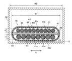
- 1 is a cross-sectional view along the short direction of a robot cable according to one embodiment
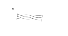
- FIG. FIG. 2 illustrates a twisted pair cable
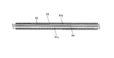
- FIG. 2 is a longitudinal cross-sectional view of a robot cable according to one embodiment
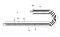
- FIG. 4 is a cross-sectional view showing a state in which the robot cable is bent according to one embodiment
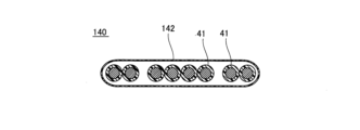
- FIG. 10 is a cross-sectional view along the short direction of the robot cable according to the first modified example
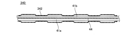
- FIG. 11 is a cross-sectional view along the longitudinal direction of a robot cable according to a second modified example
- FIG. 11 is a cross-sectional view along the longitudinal direction of a robot cable according to a third modified example
- FIG. 11 is a cross-sectional view along the short direction of a robot cable according to a fourth modified example
- It is a figure which shows the board
- FIG. 1 The configuration of the substrate transport robot 100 according to the present embodiment will be described with reference to FIGS. 1 to 5.
- the substrate transport robot 100 includes a hand 10 that holds a substrate made of a semiconductor wafer, and an arm 20 that moves the hand 10 .
- Hand 10 is attached to arm 20 .
- the arm 20 includes a first arm portion 21 attached to an elevating portion 31 to be described later, and a second arm portion 22 arranged above the first arm portion 21 .
- the substrate transport robot 100 may transport maintenance members other than semiconductor wafers, such as package substrates, glass substrates, panels, and focus rings.
- the hand 10 is attached to the arm 20 and moves linearly. Specifically, the hand 10 linearly moves along the horizontal direction.
- the hand 10 includes a holding portion 11 that holds the substrate, and an attachment portion 12 to which the holding portion 11 is attached and that slides on the second arm portion 22 .
- Two holding portions 11 are attached so as to overlap vertically with respect to the attaching portion 12 .
- the substrate transport robot 100 has a columnar housing 30 including an elevating section 31 for elevating the arm 20 .
- the elevating unit 31 elevates at the end of the housing 30 .
- the arm 20 is attached to the lifting section 31 . As a result, the arm 20 moves up and down together with the lifting section 31 .
- the substrate transport robot 100 is equipped with a robot cable 40 .
- the robot cable 40 is arranged inside the arm 20 and moves together with the linearly moving hand 10 . Further, the robot cable 40 is arranged inside the housing 30 and moves together with the arm 20 that ascends and descends. Specifically, one end of the robot cable 40 is connected to a control board, a power supply board, and the like arranged inside the arm 20 .
- the robot cable 40 is passed through the inside of the lifting section 31 via the inside of the arm 20 .
- a robot cable 40 extending from the arm 20 is inserted into the housing 30 from the lifting section 31 .
- a connector is connected to the other end of the robot cable 40 .
- a connector of the robot cable 40 is connected to a connector of a cable extending from the robot controller.
- the substrate transport robot 100 is equipped with a cable guide section 50 .
- the cable guide part 50 on which the robot cable 40 is arranged, deforms so as to follow the moving robot cable 40.
- the cable guide portion 50 is made of, for example, Cableveyor (registered trademark).
- the cable guide portion 50 is arranged inside the arm 20 and inside the housing 30 .
- the cable guide portion 50 arranged inside the arm 20 is hereinafter referred to as a cable guide portion 51 .
- Two cable guide portions 51 are arranged inside the arm 20 .
- the cable guide portion 50 arranged inside the housing 30 is referred to as a cable guide portion 52 .
- One end 50a of the cable guide portion 50 is a fixed end, and the other end 50b is a moving end.
- the robot cable 40 is arranged across two cable guides 51 and 52 .
- the other end 50b of the cable guide portion 51 moves due to the linear movement of the hand 10 along the horizontal direction.
- the shape of the cable guide portion 51 changes.
- the shape of the robot cable 40 also changes so that the shape of the cable guide portion 51 follows the change.
- the cable guide portion 51 after movement is indicated by a chain double-dashed line.
- the other end 50b of the cable guide portion 52 moves.
- the shape of the cable guide part 52 changes.
- the shape of the robot cable 40 also changes so that the shape of the cable guide portion 52 follows the change.
- the cable guide portion 52, the hand 10, and the arm 20 after movement are indicated by two-dot chain lines.
- the robot cable 40 includes a plurality of wirings 41 and a tubular member 42 that covers the plurality of wirings 41 with play.
- the plurality of wires 41 are arranged in a row inside the tubular member 42 .
- the wiring 41 is composed of a conducting wire 411 made of copper or the like and an insulating coating 412 covering the conducting wire 411 .
- the wiring 41 may be composed of one electric wire, or may be a twisted pair cable in which two electric wires are twisted together as shown in FIG.
- a cable means a composite cable including a plurality of wires 41 and a sheath covering the plurality of wires 41 .
- Tubular member 42 is a sheath.
- "play” means that a gap C1 is generated between the tubular member 42 and the wiring 41. As shown in FIG. The size of the gap C1 is smaller than the diameter of the wiring 41, for example.
- the diameter of the wiring 41 is the diameter r1 of the first wiring 41a and the diameter r2 of the second wiring 41b, which will be described later.
- tubular member 42 is thermally shrunk.
- tubular member 42 is formed from polyolefin.
- tubular member 42 is made of a transparent member.
- tubular member 42 is formed from a transparent polyolefin.
- the outside of the tubular member 42 is covered with a braided wire 43.
- the braided wire 43 is formed by weaving copper wires or fibers into a mesh.
- the braided wire 43 makes it possible to shield electrical noise.
- At least one end of the tubular member 42 covering the multiple wires 41 is fixed to the multiple wires 41 .
- at least one end of the tubular member 42 is fixed to the plurality of wirings 41 by contracting.
- substantially the entire tubular member 42 is heat-shrunk.
- the ends of the tubular member 42 are longitudinal ends along which the tubular member 42 extends.
- the cross section of the tubular member 42 has a flat shape.
- the cross-section of the tubular member 42 before heat shrinking has a circular shape.
- a sheet-like member 44 which will be described later, is arranged inside the tubular member 42, so that the cross-section of the tubular member 42 after heat shrinking has a flat shape.
- the width W1 of the cross section of the tubular member 42 in the A direction is slightly smaller than the width W2 of the area of the cable guide portion 50 where the robot cable 40 is arranged.
- the A direction is the longitudinal direction in the cross section of the flattened tubular member 42 . Accordingly, when an air pipe other than the robot cable 40 is arranged inside the cable guide portion 50, it is possible to prevent the robot cable 40 from running over the air pipe.
- the moving end 40a of the robot cable 40 slides.
- the flat surface 42a of the flat tubular member 42 faces the surface S on which the robot cable 40 slides.
- the moving end 40a of the robot cable 40 arranged inside the cable guide portion 51 of FIG. 1 slides along the horizontal plane.
- the flat surface 42a of the tubular member 42 arranged inside the cable guide portion 51 faces the horizontal surface. 1 slides along the vertical plane.
- the flat surface 42a of the tubular member 42 disposed inside the cable guide portion 52 of FIG. 1 faces the vertical surface.
- the robot cable 40 includes a sheet-like member 44 arranged inside a tubular member 42 and on which a plurality of wires 41 are placed.
- sheet member 44 is made of ultra-high molecular weight polyethylene (UPE).
- UPE ultra-high molecular weight polyethylene
- FIG. 4 the sheet member 44 is arranged from one longitudinal end to the other longitudinal end of the tubular member 42 .
- the sheet member 44 is arranged to extend from the vicinity of one end in the direction A to the vicinity of the other end in the cross section of the flat tubular member 42 .
- a gap C2 between the sheet-like member 44 and the tubular member 42 in the A direction is relatively small.
- the size of gap C2 is smaller than the diameter of wiring 41 .
- the plurality of wirings 41 are arranged in a row on the surface of the sheet member 44 .
- the plurality of wirings 41 includes a plurality of first wirings 41a and second wirings 41b.
- the first wirings 41 a are arranged in a row on one side of the sheet-like member 44 inside the tubular member 42 .
- the second wirings 41b are arranged in a row on the other side of the sheet-like member 44 inside the tubular member 42 .
- the diameter r1 of the first wiring 41a is larger than the diameter r2 of the second wiring 41b.
- the first wiring 41a is, for example, a power supply line for supplying power
- the second wiring 41b is a signal line for transmitting signals.
- the first wiring 41a is arranged on the outer diameter side while the cable guide portion 50 is curved.
- the second wiring 41b is arranged on the inner diameter side while the cable guide portion 50 is curved. Accordingly, in the cable guide portion 50 in a curved state, the radius of curvature of the first wiring 41a becomes larger than the radius of curvature of the second wiring 41b.
- the substrate transport robot 100 is arranged in the clean room 1 as shown in FIG.
- a fan for discharging the air inside the housing 30 to the outside is arranged inside the housing 30 . Air discharged by the fan is discharged below the clean room 1 through holes formed in the floor surface 1 a of the housing 30 .
- a housing 30 of the substrate transfer robot 100 is fixed to the floor 1 a of the clean room 1 .
- the tubular member 42 covers the plurality of wirings 41 with play.
- the plurality of wires 41 are arranged in a row inside the tubular member 42 . Therefore, unlike the case where a relatively large number of wires 41 are twisted and bundled together, the inner wires 41 do not spread the outer wires 41 . Therefore, it is possible to suppress the occurrence of kinks caused by the inner wiring 41 pushing out the outer wiring 41 . As a result, even when the robot cable 40 is deformed, it is possible to prevent the wiring 41 inside the robot cable 40 from being cut.
- the substrate transport robot 100 includes the cable guide section 50 on which the robot cable 40 is arranged and which deforms so as to follow the moving robot cable 40 . Accordingly, even when the robot cable 40 that deforms together with the cable guide portion 50 is deformed, it is possible to prevent the wiring 41 inside the robot cable 40 from being cut. In addition, since the plurality of wires 41 are covered with the tubular member 42, even when the robot cables 40 are arranged in the cable guide portion 50, the wires 41 due to the contact between the robot cables 40 and the cable guide portion 50 are not prevented. damage can be suppressed.
- At least one end of the tubular member 42 covering the multiple wires 41 is fixed to the multiple wires 41 as described above. As a result, it is possible to suppress displacement of the tubular member 42 with respect to the plurality of wirings 41 .
- At least one end of the tubular member 42 is shrunk and fixed to the plurality of wirings 41 .
- the plurality of wirings 41 are fixed to each other by the contracted ends of the tubular members 42, so that the plurality of wirings 41 can be restrained from being dispersed.
- substantially all of the tubular member 42 covering the plurality of wirings 41 is contracted.
- the robot cable 40 includes the sheet-like member 44 arranged inside the tubular member 42 and on which the plurality of wires 41 are placed.
- the wirings 41 are aligned on the surface of the sheet-like member 44 , so that the wirings 41 can be easily maintained in a row inside the tubular member 42 .
- the sheet-like member 44 can prevent the plurality of wirings 41 arranged in a row from becoming loose.
- the plurality of wirings 41 are arranged in a row on one side of the sheet-shaped member 44 inside the tubular member 42, and Inside the tubular member 42, on the other side of the sheet-shaped member 44, a plurality of second wirings 41b arranged in a row are included. Accordingly, it is possible to prevent the first wiring 41 a and the second wiring 41 b of different types from being mixed inside the tubular member 42 . Also, when the robot cable 40 is bent, the first wiring 41a with a large diameter r1 is arranged on the outer diameter side, and the second wiring 41b with a small diameter r2 is arranged on the inner diameter side. As a result, the first wiring 41a having a large permissible bending radius is arranged on the outer diameter side, so that even when the robot cable 40 is bent, the first wiring 41a can be prevented from being kinked.
- the tubular member 42 is thermally shrunk. Thereby, the tubular member 42 can be easily shrunk by heat. Moreover, since the tubular member 42 has a relatively large diameter before being thermally shrunk, the plurality of wirings 41 can be easily passed through the tubular member 42 .
- the cross section of the tubular member 42 has a flat shape.
- the robot cable 40 can be bent while maintaining the state in which the plurality of wires 41 are arranged in a row inside the tubular member 42 .
- the slack of the wirings 41 inside the tubular member 42 is relatively small compared to the case where the tubular member 42 has a circular cross section.
- the tubular member 42 has a flattened cross section, the thickness of the robot cable 40 is relatively small, so the height of the cable guide portion 50 that guides the robot cable 40 can be reduced.
- the moving end 40a of the robot cable 40 slides, and the flat surface 42a of the flat tubular member 42 faces the surface S on which the robot cable 40 slides. .
- the robot cable 40 can be stably arranged with respect to the plane S. Therefore, unintended deformation of the robot cable 40 such as twisting of the robot cable 40 can be suppressed when the robot cable 40 is moved.
- the tubular member 42 is made of a transparent member. As a result, the wiring 41 inside the tubular member 42 can be visually recognized, so that the state of the wiring 41 can be confirmed even after the plurality of wirings 41 are covered with the tubular member 42 .
- the substrate transport robot 100 is arranged in the clean room 1 as described above.
- the substrate transport robot 100 arranged in the clean room 1 may perform many repetitive operations.
- the robot cable 40 is repeatedly deformed. Therefore, as described above, arranging the plurality of wirings 41 in a row with some leeway inside the tubular member 42 to suppress the occurrence of kinks is effective for clean rooms that are difficult to maintain. This is particularly effective in that the frequency of maintenance of the robot cables 40 of the substrate transport robots 100 arranged in 1 can be reduced.
- the robot cable 40 is arranged inside the arm 20 to which the linearly moving hand 10 is attached, and moves together with the linearly moving hand 10 .
- the linearly moving hand 10 is repeatedly linearly moved.
- the robot cable 40 is repeatedly deformed. Therefore, by arranging the plurality of wirings 41 in a row with some leeway inside the tubular member 42 as described above to suppress the occurrence of kinks, the linearly moving hand 10 It is particularly useful for robot cables 40 that move with the robot.
- the robot cable 40 is arranged inside the housing 30 via the arm 20, and moves together with the arm 20 that moves up and down.
- the arm 20 may move up and down repeatedly.
- the robot cable 40 is repeatedly deformed. Therefore, as described above, by arranging the plurality of wires 41 inside the tubular member 42 in a state in which there is play and is arranged in a row to suppress the occurrence of kinks, the arm 20 that moves up and down It is particularly effective for robot cables 40 that move.
- the robot cable 40 is arranged in the housing 30 including the arm 20 and the lifting section 31 , but the present disclosure is not limited to this.
- the robot cable 40 may be arranged only on the arm 20, only on the housing 30 including the lifting section 31, or only on the horizontal base 60, which will be described later.
- the robot cable 40 may be arranged on two of the arm 20, the housing 30 including the lifting section 31, and the horizontal base 60, which will be described later.
- the present disclosure is not limited to this.
- the cable guide portion 50 may not be arranged.
- the robot cable 40 may be moved and deformed without the cable guide portion 50, with one end of the robot cable 40 as a fixed end and the other end as a moving end.
- the sheet-like member 44 is arranged inside the tubular member 42 , but the present disclosure is not limited to this.
- the sheet-like member 44 may not be arranged inside the tubular member 142.
- the plurality of wirings 41 are arranged in a row.
- the cross section of the tubular member 142 has a flat shape.
- the present disclosure is not limited to this.
- the outside of the tubular member 142 may not be covered with the braided wire 43 .
- tubular member 242 may be thermally shrunk.
- both ends of the tubular member 242 are heat-shrunk in FIG. 7, only one end may be heat-shrunk.
- the tubular member 342 may be partially thermally shrunk.
- FIGS. 7 and 8 show an example in which the braided wire 43 is not arranged, the outside of the tubular member 242 and the tubular member 342 may be covered with the braided wire 43 .
- tubular member 42 is thermally shrunk
- tubular member 42 may be shrunk by factors other than heat.
- the tubular member 42 is fixed to the plurality of wirings 41 by being heat-shrunk, but the present disclosure is not limited to this.
- the non-heat-shrinkable tube is fixed to the plurality of wires 41. good too.
- the cross section of the tubular member 42 has a flat shape
- the present disclosure is not limited to this.
- the cross section of tubular member 42 may have a circular shape.
- tubular member 42 is made of a transparent member, but the present disclosure is not limited to this.
- tubular member 42 may have a color.
- the present disclosure is not limited to this. It is possible to apply the present disclosure to the substrate transport robot 100 that is arranged in a place other than the clean room 1 .
- the present disclosure is not limited to this. It is also possible to apply the present disclosure to robots other than the substrate transport robot 100 .
- the wiring 41 may be arranged only on one side of the sheet member 44 .
- FIG. 9 shows an example in which the first wiring 41a is arranged on the side of the surface S on which the robot cable 40 slides.
- the case 30 of the substrate transport robot 100 is fixed to the floor 1a of the clean room 1, but the present disclosure is not limited to this.
- the housing 30 of the substrate transport robot 100 may be placed on the horizontal base 60 .
- the horizontal base 60 moves the housing 30 horizontally.
- the robot cable 40 is arranged inside the arm 20 and moves together with the linearly moving hand 10 .
- the robot cable 40 is arranged inside the housing 30 and moves together with the arm 20 that ascends and descends.
- the robot cable 40 is arranged inside the horizontal base 60 and moves along with the horizontal movement of the housing 30 .
- the robot cable 40 is arranged inside the cable guide portion 50 .
- the cable guide portion 50 includes a cable guide portion 51 arranged inside the arm 20, a cable guide portion 52 arranged inside the housing 30, and a cable guide portion arranged inside the horizontal base 60. a portion 53;
Landscapes
- Engineering & Computer Science (AREA)
- Mechanical Engineering (AREA)
- Robotics (AREA)
- Architecture (AREA)
- Civil Engineering (AREA)
- Structural Engineering (AREA)
- Microelectronics & Electronic Packaging (AREA)
- Manipulator (AREA)
- Container, Conveyance, Adherence, Positioning, Of Wafer (AREA)
Abstract
Description
本実施形態では、上記のように、チューブ状部材42は、複数の配線41を、あそびを有した状態で覆う。これにより、ロボットケーブル40が変形しても、チューブ状部材42の内部にロボットケーブル40の変形に伴って変形した配線41が移動して逃げるスペースがある。このため、変形した配線41が逃げるスペースがないことに起因するキンクの発生を抑制することができる。また、複数の配線41は、チューブ状部材42の内部において、一列に並べられた状態で配置されている。このため、比較的多くの配線41がより合わされて1本に束ねられている場合のように、内側の配線41が外側の配線41を押し広げることもない。このため、内側の配線41が外側の配線41を押し広げることに起因するキンクの発生を抑制することができる。これらにより、ロボットケーブル40が変形した場合でも、ロボットケーブル40の内部の配線41が切断することを抑制することができる。
なお、今回開示された実施形態は、すべての点で例示であって制限的なものではないと考えられるべきである。本開示の範囲は、上記した実施形態の説明ではなく請求の範囲によって示され、さらに請求の範囲と均等の意味および範囲内でのすべての変更(変形例)が含まれる。
10 ハンド
20 アーム
30 筐体
31 昇降部
40、140、240、340、440 ロボットケーブル
40a 移動端
41 配線
41a 第1配線
41b 第2配線
42、142、242、342 チューブ状部材
44 シート状部材
50、51、52、53 ケーブル案内部
60 水平基台
100 基板搬送ロボット(ロボット)
S 面
Claims (13)
- クリーンルームに配置されているロボットであって、
直線移動するハンドが取り付けられるアームの内部と、前記アームを昇降させる昇降部を含む柱状の筐体の内部と、前記筐体を水平方向に沿って移動させる水平基台の内部と、のうちの少なくとも1つに配置されているロボットケーブルを備え、
前記ロボットケーブルは、
複数の配線と、
前記複数の配線を、あそびを有した状態で覆うチューブ状部材と、を含み、
前記複数の配線は、前記チューブ状部材の内部において、一列に並べられた状態で配置されている、ロボット。 - 前記ロボットケーブルが配置され、移動する前記ロボットケーブルに追従するように変形するケーブル案内部をさらに備える、請求項1に記載のロボット。
- 前記複数の配線を覆う前記チューブ状部材の少なくとも一方の端部は、前記複数の配線に対して固定されている、請求項1に記載のロボット。
- 前記チューブ状部材の少なくとも一方の端部は、収縮されることにより、前記複数の配線に対して固定されている、請求項3に記載のロボット。
- 前記ロボットケーブルは、前記チューブ状部材の内部に配置され、前記複数の配線が載置されるシート状部材をさらに含む、請求項1に記載のロボット。
- 前記複数の配線は、
前記チューブ状部材の内部において、前記シート状部材の一方側において一列に並べられた状態で配置される複数の第1配線と、
前記チューブ状部材の内部において、前記シート状部材の他方側において、一列に並べられた状態で配置される複数の第2配線と、を含む、請求項5に記載のロボット。 - 前記チューブ状部材は、熱収縮する、請求項1に記載のロボット。
- 前記チューブ状部材の断面は、扁平形状を有する、請求項1に記載のロボット。
- 前記ロボットケーブルの移動端は、スライド移動し、
扁平形状の前記チューブ状部材の平坦面は、前記ロボットケーブルがスライド移動する面に対向している、請求項8に記載のロボット。 - 前記チューブ状部材は、透明の部材からなる、請求項1に記載のロボット。
- 前記アームと、
前記アームに取り付けられ、直線移動する前記ハンドと、をさらに備え、
前記ロボットケーブルは、前記アームの内部に配置されており、直線移動する前記ハンドとともに移動する、請求項1に記載のロボット。 - 前記アームと、
前記アームを昇降させる前記昇降部を含む柱状の前記筐体と、をさらに備え、
前記ロボットケーブルは、前記アームを介して前記筐体の内部に配置されており、昇降する前記アームとともに移動する、請求項1に記載のロボット。 - 前記アームと、
前記アームを昇降させる前記昇降部を含む柱状の前記筐体と、
前記筐体を水平方向に沿って移動させる水平基台と、をさらに備え、
前記ロボットケーブルは、前記水平基台の内部に配置されており、水平方向に沿って移動する前記筐体とともに移動する、請求項1に記載のロボット。
Priority Applications (2)
| Application Number | Priority Date | Filing Date | Title |
|---|---|---|---|
| US18/560,466 US20240253912A1 (en) | 2021-08-05 | 2022-07-13 | Robot |
| JP2023539736A JP7707302B2 (ja) | 2021-08-05 | 2022-07-13 | ロボット |
Applications Claiming Priority (2)
| Application Number | Priority Date | Filing Date | Title |
|---|---|---|---|
| JP2021-129011 | 2021-08-05 | ||
| JP2021129011 | 2021-08-05 |
Publications (1)
| Publication Number | Publication Date |
|---|---|
| WO2023013376A1 true WO2023013376A1 (ja) | 2023-02-09 |
Family
ID=85155968
Family Applications (1)
| Application Number | Title | Priority Date | Filing Date |
|---|---|---|---|
| PCT/JP2022/027606 Ceased WO2023013376A1 (ja) | 2021-08-05 | 2022-07-13 | ロボット |
Country Status (4)
| Country | Link |
|---|---|
| US (1) | US20240253912A1 (ja) |
| JP (1) | JP7707302B2 (ja) |
| TW (1) | TWI818645B (ja) |
| WO (1) | WO2023013376A1 (ja) |
Families Citing this family (3)
| Publication number | Priority date | Publication date | Assignee | Title |
|---|---|---|---|---|
| US12459621B1 (en) | 2022-09-07 | 2025-11-04 | Brunswick Corporation | Marine drives and apparatuses for steering marine drives and for routing flexible rigging connectors on marine drives |
| US12459622B1 (en) | 2022-10-25 | 2025-11-04 | Brunswick Corporation | Marine drives and apparatuses for steering marine drives and for routing flexible rigging connectors on marine drives |
| US12420900B1 (en) | 2023-01-03 | 2025-09-23 | Brunswick Corporation | Marine drives having a retainer for flexible rigging connectors |
Citations (7)
| Publication number | Priority date | Publication date | Assignee | Title |
|---|---|---|---|---|
| JPH0413594A (ja) * | 1990-05-07 | 1992-01-17 | Matsushita Electric Ind Co Ltd | ロボット用ケーブルユニット |
| JPH04111787A (ja) * | 1990-08-31 | 1992-04-13 | Tokico Ltd | 塗装用ロボット |
| JPH07136973A (ja) * | 1993-11-12 | 1995-05-30 | Matsushita Electric Ind Co Ltd | 直交ロボット |
| JPH09141591A (ja) * | 1995-11-21 | 1997-06-03 | Shibaura Eng Works Co Ltd | 産業用ロボット |
| JP2016076433A (ja) * | 2014-10-08 | 2016-05-12 | 日立金属株式会社 | 可動部配線用フラットケーブル |
| JP2017103096A (ja) * | 2015-12-01 | 2017-06-08 | 旭化成株式会社 | 止水性を備えたケーブル付電子部品 |
| JP2019175839A (ja) * | 2018-03-27 | 2019-10-10 | 日立金属株式会社 | 絶縁電線及び多芯ケーブル |
Family Cites Families (2)
| Publication number | Priority date | Publication date | Assignee | Title |
|---|---|---|---|---|
| KR20160023524A (ko) | 2014-08-21 | 2016-03-03 | 엘에스전선 주식회사 | 멀티미디어용 광전복합 케이블 |
| CN111673722A (zh) * | 2020-07-13 | 2020-09-18 | 广东万家乐燃气具有限公司 | 一种搬运机械手及无人厨房 |
-
2022
- 2022-07-13 JP JP2023539736A patent/JP7707302B2/ja active Active
- 2022-07-13 US US18/560,466 patent/US20240253912A1/en active Pending
- 2022-07-13 WO PCT/JP2022/027606 patent/WO2023013376A1/ja not_active Ceased
- 2022-07-27 TW TW111128175A patent/TWI818645B/zh active
Patent Citations (7)
| Publication number | Priority date | Publication date | Assignee | Title |
|---|---|---|---|---|
| JPH0413594A (ja) * | 1990-05-07 | 1992-01-17 | Matsushita Electric Ind Co Ltd | ロボット用ケーブルユニット |
| JPH04111787A (ja) * | 1990-08-31 | 1992-04-13 | Tokico Ltd | 塗装用ロボット |
| JPH07136973A (ja) * | 1993-11-12 | 1995-05-30 | Matsushita Electric Ind Co Ltd | 直交ロボット |
| JPH09141591A (ja) * | 1995-11-21 | 1997-06-03 | Shibaura Eng Works Co Ltd | 産業用ロボット |
| JP2016076433A (ja) * | 2014-10-08 | 2016-05-12 | 日立金属株式会社 | 可動部配線用フラットケーブル |
| JP2017103096A (ja) * | 2015-12-01 | 2017-06-08 | 旭化成株式会社 | 止水性を備えたケーブル付電子部品 |
| JP2019175839A (ja) * | 2018-03-27 | 2019-10-10 | 日立金属株式会社 | 絶縁電線及び多芯ケーブル |
Also Published As
| Publication number | Publication date |
|---|---|
| US20240253912A1 (en) | 2024-08-01 |
| JPWO2023013376A1 (ja) | 2023-02-09 |
| TWI818645B (zh) | 2023-10-11 |
| TW202322999A (zh) | 2023-06-16 |
| JP7707302B2 (ja) | 2025-07-14 |
Similar Documents
| Publication | Publication Date | Title |
|---|---|---|
| TWI818645B (zh) | 機器人 | |
| CN101277006B (zh) | 基板搬运装置和电缆配线构造 | |
| JP5322755B2 (ja) | ケーブル | |
| US20110005805A1 (en) | Cable | |
| JP4989693B2 (ja) | ケーブル | |
| US20070031232A1 (en) | Industrial robot | |
| JP2004136371A (ja) | 産業用ロボットのカメラ及び力センサケーブル処理構造 | |
| JP5358048B2 (ja) | 自立型ケーブル | |
| KR102649464B1 (ko) | 복합 케이블 | |
| US12224087B2 (en) | Stretchable cable | |
| JP6898577B1 (ja) | ケーブルハーネス、ケーブルハーネスの製造方法及びケーブルハーネスを有する産業用ロボット | |
| KR100898592B1 (ko) | 발열 케이블 | |
| JP2020087681A (ja) | 可動部用ケーブル | |
| EP0744253B1 (en) | Industrial robot with lead wire processing device | |
| JP2003168326A (ja) | ケーブルハーネス | |
| KR20240054767A (ko) | 단선방지 구조를 포함하는 다관절 매니퓰레이트 | |
| KR102726965B1 (ko) | 카본 섬유 케이블 및 그 제조 방법 | |
| JP3192559B2 (ja) | 光ファイバ入キャブタイヤケーブル | |
| JP2007288972A (ja) | ワイヤハーネス分岐部の保護構造 | |
| CN214476570U (zh) | 一种易于敷设的耐扭、耐低温电缆 | |
| CN223194114U (zh) | 一种易排布抗扭曲的ffc排线 | |
| CN221352418U (zh) | 一种耐折弯的控制线 | |
| CN219286077U (zh) | 一种机器人用柔性光电复合缆 | |
| JP4793687B2 (ja) | 多関節ロボット | |
| KR100830766B1 (ko) | 산업 로봇용 파워 케이블 |
Legal Events
| Date | Code | Title | Description |
|---|---|---|---|
| 121 | Ep: the epo has been informed by wipo that ep was designated in this application |
Ref document number: 22852802 Country of ref document: EP Kind code of ref document: A1 |
|
| WWE | Wipo information: entry into national phase |
Ref document number: 18560466 Country of ref document: US |
|
| NENP | Non-entry into the national phase |
Ref country code: DE |
|
| ENP | Entry into the national phase |
Ref document number: 2023539736 Country of ref document: JP Kind code of ref document: A |
|
| 122 | Ep: pct application non-entry in european phase |
Ref document number: 22852802 Country of ref document: EP Kind code of ref document: A1 |