WO2023013106A1 - 画像処理装置、および、画像データ送信方法 - Google Patents
画像処理装置、および、画像データ送信方法 Download PDFInfo
- Publication number
- WO2023013106A1 WO2023013106A1 PCT/JP2022/004805 JP2022004805W WO2023013106A1 WO 2023013106 A1 WO2023013106 A1 WO 2023013106A1 JP 2022004805 W JP2022004805 W JP 2022004805W WO 2023013106 A1 WO2023013106 A1 WO 2023013106A1
- Authority
- WO
- WIPO (PCT)
- Prior art keywords
- image processing
- image data
- image
- unit
- noise
- Prior art date
- Legal status (The legal status is an assumption and is not a legal conclusion. Google has not performed a legal analysis and makes no representation as to the accuracy of the status listed.)
- Ceased
Links
Images





Classifications
-
- H—ELECTRICITY
- H04—ELECTRIC COMMUNICATION TECHNIQUE
- H04N—PICTORIAL COMMUNICATION, e.g. TELEVISION
- H04N23/00—Cameras or camera modules comprising electronic image sensors; Control thereof
- H04N23/60—Control of cameras or camera modules
- H04N23/66—Remote control of cameras or camera parts, e.g. by remote control devices
-
- H—ELECTRICITY
- H04—ELECTRIC COMMUNICATION TECHNIQUE
- H04N—PICTORIAL COMMUNICATION, e.g. TELEVISION
- H04N7/00—Television systems
- H04N7/18—Closed-circuit television [CCTV] systems, i.e. systems in which the video signal is not broadcast
- H04N7/183—Closed-circuit television [CCTV] systems, i.e. systems in which the video signal is not broadcast for receiving images from a single remote source
-
- Y—GENERAL TAGGING OF NEW TECHNOLOGICAL DEVELOPMENTS; GENERAL TAGGING OF CROSS-SECTIONAL TECHNOLOGIES SPANNING OVER SEVERAL SECTIONS OF THE IPC; TECHNICAL SUBJECTS COVERED BY FORMER USPC CROSS-REFERENCE ART COLLECTIONS [XRACs] AND DIGESTS
- Y02—TECHNOLOGIES OR APPLICATIONS FOR MITIGATION OR ADAPTATION AGAINST CLIMATE CHANGE
- Y02D—CLIMATE CHANGE MITIGATION TECHNOLOGIES IN INFORMATION AND COMMUNICATION TECHNOLOGIES [ICT], I.E. INFORMATION AND COMMUNICATION TECHNOLOGIES AIMING AT THE REDUCTION OF THEIR OWN ENERGY USE
- Y02D10/00—Energy efficient computing, e.g. low power processors, power management or thermal management
Definitions
- the present invention relates to an image processing device and an image data transmission method that suppress quality deterioration due to extraneous noise when transmitting image data output from an imaging device to an image processing circuit.
- Patent Document 1 proposes a method of using software to reduce the deterioration of communication quality due to the influence of external noise.
- the abstract of the document states that the problem is to "provide an imaging device capable of reducing noise caused by the influence of an actuator or the like without affecting the frame rate.”
- a pixel section in which a plurality of pixels that perform photoelectric conversion are arranged in a matrix a pixel signal readout section including a function of reading a reset level and a signal level of pixels from the pixel section to a signal line, and the pixel signal readout
- the pixel signal readout unit has a column-parallel type ADC (Analog digital converter) unit that converts analog signals read out corresponding to the column arrangement of pixels into digital signals.
- ADC Analog digital converter
- timing changing means for changing readout timing of the pixel signal readout section
- storage means for storing frequency information of noise generated during operation of the pixel signal readout section; determines the readout timing of the pixel signal readout unit and the resolution (number of bits) of AD conversion.”
- the bit depth of the image data can be reduced (for example, from RAW12 format to RAW10 format image data). change), it becomes difficult to recognize the color difference of the captured outside world, and there is a problem that the accuracy of recognizing the outside world deteriorates.
- the bit depth of the image data is increased (for example, changing from RAW12 format to RAW14 format image data), the processing capacity of the image processing circuit for recognizing the external world will be insufficient, and the image processing circuit will be consumed. There is a problem that the amount of heat generated increases due to the increase in electric power.
- bit depth of the image data when the bit depth of the image data is changed, it is necessary to switch the image processing algorithm of the image processing circuit, but since the image processing algorithm cannot be switched dynamically, the bit depth of the image data is changed. Each time, it is necessary to temporarily stop the image processing circuit and provide a period for switching the image processing algorithm, and during that period the external environment cannot be recognized. There was also a fatal problem.
- an object of the present invention is to provide an image processing apparatus and an image data transmission method that suppress deterioration of communication quality due to external noise while maintaining the bit depth and frame rate of image data.
- the present invention provides an image pickup device that acquires image data at a predetermined frame rate, an image processing unit that processes the image data, and the image pickup device that provides the image processing unit with: a transmission unit that transmits image data at a predetermined communication frequency; and a communication control unit that instructs the transmission unit to change the communication frequency while maintaining the predetermined frame rate according to the frequency of external noise. It is used as an image processing device.
- the image processing device and the image data transmission method of the present invention deterioration of communication quality due to external noise can be suppressed while maintaining the bit depth and frame rate of image data.
- FIG. 1 is a front view of a vehicle equipped with an image processing device according to Embodiment 1;
- FIG. 2 is a functional block diagram showing the configuration of the image processing apparatus according to the first embodiment;
- FIG. 4 is a processing flowchart of the image processing apparatus according to the first embodiment;
- An example of the noise level of external noise An example of the relationship between the communication reference frequency and the post-change frequency
- FIG. 4 is an explanatory diagram of an error correction method using the same image data of two sheets;
- FIG. 10 is a functional block diagram showing the configuration of an image processing apparatus according to a second embodiment;
- FIG. 1 is a front view of a vehicle V to which an image processing device 100 according to Example 1 of the present invention is attached. As shown here, the image processing device 100 is attached to the upper inner surface of the windshield of the vehicle V, which is an environment susceptible to external noise, so that the image of the front of the vehicle V can be captured. Note that FIG. 1 illustrates the image processing device 100 that captures an image of the front of the vehicle V, but the image processing device 100 that captures an image of the rear or sides of the vehicle V may be provided.
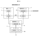
- FIG. 2 is a functional block diagram of the image processing device 100 of FIG.
- the image processing device 100 is a device for recognizing the external environment of the vehicle V when executing vehicle control such as emergency automatic braking and preceding vehicle following control (ACC). , an antenna 3 , and a communication control unit 4 .
- vehicle control such as emergency automatic braking and preceding vehicle following control (ACC).
- ACC emergency automatic braking and preceding vehicle following control
- the imaging unit 1 and the image processing unit 2 are installed on the same substrate with a certain distance therebetween, and are connected to each other via wiring patterns on the substrate and communication cables. and Details of each unit will be described below.
- the imaging unit 1 is a unit for outputting image data D with a predetermined bit depth after capturing an image of the external environment of the vehicle V at a predetermined frame rate, and has an imaging unit 11 and a transmission unit 12 .
- the imaging unit 11 is a combination of pixels (photodiodes, etc.) of an imaging device (CMOS image sensor, etc.), logic circuits, etc., and after imaging the external environment of the vehicle V at a predetermined frame rate, image data D is output.
- the imaging unit 1 may be a monocular camera or a compound eye camera such as a stereo camera.
- the transmission unit 12 transmits the image data D captured by the imaging unit 11 to the image processing unit 2 using a predetermined communication protocol.
- the communication protocol used here is, for example, MIPI CSI-2 (Mobile Industry Processor Interface, registered trademark), which is an interface standard for mobile device cameras.
- the image processing unit 2 is a unit for recognizing the external environment of the vehicle V, and has a receiving section 21 and an image recognition section 22 .
- the receiving unit 21 decodes the image data D of the predetermined communication protocol received from the transmitting unit 12 into a format that can be processed by the image recognizing unit 22 at the next stage.
- the image recognition unit 22 performs image processing on the decoded image data D to recognize the external environment of the vehicle V (e.g., preceding vehicles, pedestrians, traffic signs, traffic lights, white lines on the road, etc.), and as an image recognition result Output.
- the image recognition result output by the image recognition unit 22 is transmitted to an ECU (Electronic Control Unit) that controls the driving system, braking system, steering system, etc. of the vehicle V via a CAN (Controller Area Network). Used for control, etc.
- Antenna 3 is a device for receiving external noise that may affect the transmission of image data D from imaging unit 1 to image processing unit 2 . Note that it is desirable to place the antenna 3 inside the image processing apparatus 100 so that external noise that has entered the apparatus can be observed. 3 may be placed.
- the communication control unit 4 is a unit for setting the communication method from the imaging unit 1 to the image processing unit 2 to a communication method that is less susceptible to external noise. It has a control unit 43 .
- the communication control unit 4 is specifically a computer unit including hardware such as an arithmetic device such as a CPU, a storage device such as a semiconductor memory, and a communication device.
- the functions of the noise effect prediction unit 41 and the communication control unit 43 are realized by executing the program stored in the storage device by the arithmetic unit. Each part will be described while omitting it as appropriate.
- the noise influence prediction unit 41 analyzes noise information (noise level, frequency) of external noise received by the antenna 3 .
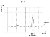
- FIG. 4 shows an example of noise information analyzed by the noise effect prediction unit 41, in which the result of Fourier transform of external noise is reflected in a two-dimensional space with the frequency on the horizontal axis and the noise level on the vertical axis.
- the noise level of the external noise is maximum near the reference frequency f0 used for communication.
- the noise influence prediction unit 41 refers to the noise resistance information 42a registered in the database 42.
- FIG. Here, the contents of the noise resistance information 42a will be specifically described with reference to FIG.
- the dotted line in the figure exemplifies the noise immunity information when the reference frequency f0 is used for communication
- the solid line in the figure exemplifies the noise immunity information when the reference frequency fX is used for communication. It is.
- any noise immunity information has low noise immunity against external noise in three frequency bands including each communication frequency. The frequency bands do not overlap. Although only two types of noise immunity information are illustrated in FIG. 5, it is assumed that the database 42 also pre-registers noise immunity information for a large number of communication frequencies other than these.
- step S3 the noise effect prediction unit 41 determines whether the transmission of the image data D from the imaging unit 1 to the image processing unit 2 is affected by external noise based on the noise resistance information 42a acquired from the database 42. . If the determination is No, the process proceeds to step S4, and if the determination is Yes, the process proceeds to step S5.
- the reference frequency f0 is used for transmitting the image data D and the noise level of the external noise is the environment shown in FIG. Since the noise level of the noise exceeds, it can be determined that the communication is affected by the noise.
- the reference frequency fX is used to transmit the image data D and the noise level of the external noise is the environment shown in FIG. Since the noise level of the noise does not exceed, it can be determined that the communication is not affected by the noise.
- the communication frequency f0 is used for transmitting the image data D and the noise level of the external noise is the environment shown in FIG. Since the noise level of the noise exceeds, it can be determined that the communication is affected by the noise.
- the reference frequency fX is used to transmit the image data D and the noise level of the external noise is the environment shown in FIG. Since the noise level of the noise does not exceed, it can be determined that the communication is not affected by the noise.
- step S4 the communication control section 43 instructs the transmission section 12 of the imaging unit 1 to continue communication at the current frequency (for example, the reference frequency f 0 ). do.
- the communication control unit 43 does not have to transmit a particular command to the transmission unit 12 because it is not necessary to change the communication frequency.
- step S5 the communication control section 43 commands the transmission section 12 of the imaging unit 1 to change the communication frequency to another frequency.
- the frequency change here is executed with reference to the noise information (noise level, frequency) of the external noise obtained in step S1 and the noise resistance information 42a obtained in step S3.
- the influence of the external noise can be avoided by changing the communication frequency from the reference frequency f0 to the frequency fX from the illustrated relationship between the external noise and the noise resistance.
- the setting value for changing the communication frequency to the frequency fX is commanded to the transmission unit 12 .
- step S6 the communication control unit 43 determines whether the communication frequency changed in step S5 is at least twice the reference frequency f0 . If the determination is No, the process proceeds to step S7, and if the determination is Yes, the process proceeds to step S8.
- step S7 if the communication frequency is less than twice the reference frequency f0 , in step S7, if the data transmission time increases or decreases due to the change in the communication frequency, the communication control unit 43 cancels out the increase or decrease in the data transmission time to achieve the desired frequency.
- a blank time is calculated so that the frame rate cycle T can be maintained, and a corresponding blank time adjustment command is output to the transmission unit 12 .
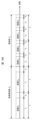
- FIG. 6A is a diagram illustrating an example of communication frequency change in this step. In FIG.
- the first half illustrates the length of data transmission time t 1 and blank time t 2 when the communication frequency is the reference frequency f 0
- the second half illustrates the length of the communication frequency f 1 (however, The lengths of data transmission time t3 and blank time t4 are illustrated when f1 ⁇ 2f0 ).
- the desired frame rate period T can be maintained by adjusting the length of the blank time.
- the frequency f1 is set higher than the reference frequency f0 (the data transmission time t3 is shorter than the data transmission time t1 ), but the frequency f1 is set lower than the reference frequency f0 (the data transmission time Data transmission time t3 may be set longer than t1 .
- a frame rate cycle T shown in FIG. 6A is a time reserved for image processing of one piece of image data D in the image processing unit 2 . If the frame rate period T is too long (if the frequency of receiving the image data D is too low), the image processing unit 2 may not be able to detect changes in the external environment appropriately due to lack of information. Conversely, if the frame rate cycle T is too short (if the frequency of receiving the image data D is excessive), the image processing unit 2 may run out of computing power and may not be able to output the image recognition results at appropriate timing. be.
- a constant frame rate cycle T that can appropriately detect changes in the external environment and that does not exceed the computational capacity of the image processing unit 2 is predetermined as a specification, and even if the communication frequency increases or decreases, I tried to keep this.
- the length of the blank time was adjusted so that the frame rate cycle T was constant, but the frame rate cycle T does not need to be strictly constant.
- the length of the frame rate cycle T may be varied within the range of .
- FIG. 6B is a diagram illustrating an example of changing the communication frequency in this step.
- the first half illustrates that the image data D is transmitted only once within one frame rate period T when the communication frequency is the reference frequency f0
- the second half illustrates that the communication frequency is frequency f 2 (where 2f 0 ⁇ f 2 ), the same image data D is transmitted twice within one frame rate cycle T.
- FIG. As shown in the latter half of FIG.
- FIG. 6B illustrates a situation in which the same image data D is continuously transmitted twice within one frame rate cycle T, but if the communication frequency is higher, the same image data may be continuously transmitted three times or more. You can send it.
- FIG. 7 is an explanatory diagram of an error correction method that can be executed by the image processing unit 2 when the same image data D is received twice within one frame rate period T.
- the image data D is transmitted from the imaging unit 1 to the image processing unit 2
- errors may occur in different parts of the first and second image data D due to the influence of external noise. Therefore, by aggregating the error-free parts of each image data D, it is possible to combine the image data D with no error (or few errors) as a whole.
- an ECC Error-Correcting Code
- checksum are added to each line into which the image data D is divided. The presence or absence of an error can be determined.
- ⁇ Effect of this embodiment> As described above, according to the image processing apparatus of this embodiment, deterioration of communication quality due to external noise can be suppressed while maintaining the bit depth and frame rate of image data. As a result, the amount of information in the image data sent to the image processing unit remains the same before and after changing the communication frequency to avoid the influence of external noise. There is no need to provide a processing suspension period for As a result, since the external world recognition process can be continued even when the communication frequency is changed, the driving support system and the automatic driving system that use the image recognition result of the image processing device of the present invention can control the vehicle according to the external environment. can be continued without a rest period.
- the image processing apparatus 100 of the first embodiment includes the antenna 3 and the noise effect prediction unit 41.
- the communication frequency was determined to avoid external noise.
- the image processing apparatus 100 of the present embodiment uses the setting value table 42b in the database 42 even if the configuration does not include the antenna 3. It is.
- the receiving section 21 in the image processing unit 2 confirms whether or not there is an error in the image data D, and determines whether or not it is affected by external noise.
- MIPI CSI-2 is used as the communication protocol
- the presence or absence of an error can be determined for each line that constitutes the image data D by referring to the ECC and checksum.
- the multiple image data D are compared to determine whether or not there is a difference. , the presence or absence of an error can be determined.
- the communication control unit 43 that has received the notification refers to the communication frequency setting value table 42b stored in the database 42, and Setting value information (communication frequency after change, etc.) selected from a plurality of setting value information registered in advance in the table is transmitted to the transmitting unit 12 . Then, the transmission unit 12 changes the communication frequency based on the received information. By repeating this process until there is no image data communication error, even if the apparatus does not have the antenna 3, the same effect as in the first embodiment can be obtained.
Landscapes
- Engineering & Computer Science (AREA)
- Multimedia (AREA)
- Signal Processing (AREA)
- Studio Devices (AREA)
Priority Applications (2)
| Application Number | Priority Date | Filing Date | Title |
|---|---|---|---|
| JP2023539607A JP7464801B2 (ja) | 2021-08-02 | 2022-02-08 | 画像処理装置、および、画像データ送信方法 |
| DE112022002740.1T DE112022002740T5 (de) | 2021-08-02 | 2022-02-08 | Bildverarbeitungsvorrichtung und bilddaten-sendeverfahren |
Applications Claiming Priority (2)
| Application Number | Priority Date | Filing Date | Title |
|---|---|---|---|
| JP2021126556 | 2021-08-02 | ||
| JP2021-126556 | 2021-08-02 |
Publications (1)
| Publication Number | Publication Date |
|---|---|
| WO2023013106A1 true WO2023013106A1 (ja) | 2023-02-09 |
Family
ID=85155482
Family Applications (1)
| Application Number | Title | Priority Date | Filing Date |
|---|---|---|---|
| PCT/JP2022/004805 Ceased WO2023013106A1 (ja) | 2021-08-02 | 2022-02-08 | 画像処理装置、および、画像データ送信方法 |
Country Status (3)
| Country | Link |
|---|---|
| JP (1) | JP7464801B2 (https=) |
| DE (1) | DE112022002740T5 (https=) |
| WO (1) | WO2023013106A1 (https=) |
Citations (4)
| Publication number | Priority date | Publication date | Assignee | Title |
|---|---|---|---|---|
| JPS5869528A (ja) * | 1981-10-20 | 1983-04-25 | 富士写真フイルム株式会社 | 内視鏡における信号伝送方式 |
| JP2000069443A (ja) * | 1998-08-25 | 2000-03-03 | N Ii C Cable Media Kk | Catv網におけるtv中継システム |
| WO2006090744A1 (ja) * | 2005-02-23 | 2006-08-31 | Matsushita Electric Industrial Co., Ltd. | カメラ付き通信端末装置 |
| JP2014064102A (ja) * | 2012-09-20 | 2014-04-10 | Aisin Seiki Co Ltd | アナログ信号通信システム |
Family Cites Families (1)
| Publication number | Priority date | Publication date | Assignee | Title |
|---|---|---|---|---|
| JP2014236252A (ja) | 2013-05-31 | 2014-12-15 | キヤノン株式会社 | 撮像装置 |
-
2022
- 2022-02-08 DE DE112022002740.1T patent/DE112022002740T5/de active Pending
- 2022-02-08 WO PCT/JP2022/004805 patent/WO2023013106A1/ja not_active Ceased
- 2022-02-08 JP JP2023539607A patent/JP7464801B2/ja active Active
Patent Citations (4)
| Publication number | Priority date | Publication date | Assignee | Title |
|---|---|---|---|---|
| JPS5869528A (ja) * | 1981-10-20 | 1983-04-25 | 富士写真フイルム株式会社 | 内視鏡における信号伝送方式 |
| JP2000069443A (ja) * | 1998-08-25 | 2000-03-03 | N Ii C Cable Media Kk | Catv網におけるtv中継システム |
| WO2006090744A1 (ja) * | 2005-02-23 | 2006-08-31 | Matsushita Electric Industrial Co., Ltd. | カメラ付き通信端末装置 |
| JP2014064102A (ja) * | 2012-09-20 | 2014-04-10 | Aisin Seiki Co Ltd | アナログ信号通信システム |
Also Published As
| Publication number | Publication date |
|---|---|
| JPWO2023013106A1 (https=) | 2023-02-09 |
| JP7464801B2 (ja) | 2024-04-09 |
| DE112022002740T5 (de) | 2024-04-11 |
Similar Documents
| Publication | Publication Date | Title |
|---|---|---|
| US7171027B2 (en) | Vehicular image processing apparatus and related method | |
| US20200051265A1 (en) | Electronic device for blurring image obtained by combining plural images based on depth information and method for driving the electronic device | |
| US10154255B2 (en) | In-vehicle-camera image processing device | |
| JP6660751B2 (ja) | 撮像装置 | |
| CN112672004B (zh) | 车辆及控制车辆的方法 | |
| WO2014148175A1 (ja) | 画像処理装置 | |
| JP7278846B2 (ja) | 物体位置検出装置、走行制御システム、および走行制御方法 | |
| US10567690B2 (en) | Imaging apparatus, imaging system, and moving body having capacitance of an electric path extending from a supply unit to a selection unit | |
| US12602923B2 (en) | Methods and apparatus to provide an efficient safety mechanism for signal processing hardware | |
| CN111869197B (zh) | 带有原始图像信号接口的汽车摄像机 | |
| US20210044775A1 (en) | Electronic device for compressing image acquired by using camera, and operation method therefor | |
| KR20220132889A (ko) | 복수의 카메라들을 포함하는 전자 장치 | |
| JP6652463B2 (ja) | 車載カメラ装置、車載カメラ調整装置及び車載カメラ調整システム | |
| JP7464801B2 (ja) | 画像処理装置、および、画像データ送信方法 | |
| US12126901B2 (en) | Electronic device and method for supporting deblurring of image data | |
| US12160666B2 (en) | Electronic device including camera with blur reduction | |
| KR20210023859A (ko) | 화상 처리 장치, 이동 장치 및 방법, 그리고 프로그램 | |
| US12015848B2 (en) | Electronic device performing image stabilization and operating method thereof | |
| US12267599B2 (en) | Image capturing method using plurality of cameras, and electronic device therefor | |
| JP6161582B2 (ja) | 画像処理装置 | |
| US11356656B2 (en) | Signal processing device, signal processing method, and signal processing system | |
| JPWO2016157873A1 (ja) | 撮像装置、撮像システム、および車両 | |
| US12563287B2 (en) | Local generation of commands to a vehicle sensor | |
| JP6171264B2 (ja) | 撮像装置 | |
| KR20200006971A (ko) | 신호 처리 장치 및 방법, 촬상 소자 및 전자 기기 |
Legal Events
| Date | Code | Title | Description |
|---|---|---|---|
| WWE | Wipo information: entry into national phase |
Ref document number: 2023539607 Country of ref document: JP |
|
| WWE | Wipo information: entry into national phase |
Ref document number: 112022002740 Country of ref document: DE |
|
| 122 | Ep: pct application non-entry in european phase |
Ref document number: 22852535 Country of ref document: EP Kind code of ref document: A1 |