WO2023008445A1 - Electric power storage module - Google Patents
Electric power storage module Download PDFInfo
- Publication number
- WO2023008445A1 WO2023008445A1 PCT/JP2022/028832 JP2022028832W WO2023008445A1 WO 2023008445 A1 WO2023008445 A1 WO 2023008445A1 JP 2022028832 W JP2022028832 W JP 2022028832W WO 2023008445 A1 WO2023008445 A1 WO 2023008445A1
- Authority
- WO
- WIPO (PCT)
- Prior art keywords
- power storage
- storage module
- holder
- storage device
- module according
- Prior art date
Links
- 238000003860 storage Methods 0.000 title claims abstract description 266
- 238000007789 sealing Methods 0.000 claims abstract description 46
- 239000000945 filler Substances 0.000 claims description 68
- 210000000078 claw Anatomy 0.000 claims description 34
- 230000003014 reinforcing effect Effects 0.000 claims description 25
- 239000011324 bead Substances 0.000 claims description 9
- 239000011521 glass Substances 0.000 claims description 9
- 230000005611 electricity Effects 0.000 claims description 8
- 238000000034 method Methods 0.000 description 19
- 239000007789 gas Substances 0.000 description 16
- 239000005001 laminate film Substances 0.000 description 16
- 239000000853 adhesive Substances 0.000 description 10
- 230000001070 adhesive effect Effects 0.000 description 10
- 230000008569 process Effects 0.000 description 8
- 230000002159 abnormal effect Effects 0.000 description 7
- 239000000463 material Substances 0.000 description 7
- 238000010586 diagram Methods 0.000 description 6
- 238000013461 design Methods 0.000 description 5
- 238000009792 diffusion process Methods 0.000 description 5
- 230000000694 effects Effects 0.000 description 5
- 239000008151 electrolyte solution Substances 0.000 description 5
- 238000004519 manufacturing process Methods 0.000 description 5
- 229910000000 metal hydroxide Inorganic materials 0.000 description 5
- 150000004692 metal hydroxides Chemical class 0.000 description 5
- 229920005992 thermoplastic resin Polymers 0.000 description 5
- 238000012546 transfer Methods 0.000 description 5
- 229920002430 Fibre-reinforced plastic Polymers 0.000 description 4
- 239000004743 Polypropylene Substances 0.000 description 4
- 230000004308 accommodation Effects 0.000 description 4
- 239000004918 carbon fiber reinforced polymer Substances 0.000 description 4
- 239000000470 constituent Substances 0.000 description 4
- 239000011151 fibre-reinforced plastic Substances 0.000 description 4
- 239000011152 fibreglass Substances 0.000 description 4
- 229910052751 metal Inorganic materials 0.000 description 4
- 239000002184 metal Substances 0.000 description 4
- 229920001707 polybutylene terephthalate Polymers 0.000 description 4
- -1 polypropylene Polymers 0.000 description 4
- 229920001155 polypropylene Polymers 0.000 description 4
- 229920005989 resin Polymers 0.000 description 4
- 239000011347 resin Substances 0.000 description 4
- 239000000565 sealant Substances 0.000 description 4
- 238000003466 welding Methods 0.000 description 4
- 230000009471 action Effects 0.000 description 3
- 229910052782 aluminium Inorganic materials 0.000 description 3
- XAGFODPZIPBFFR-UHFFFAOYSA-N aluminium Chemical compound [Al] XAGFODPZIPBFFR-UHFFFAOYSA-N 0.000 description 3
- 238000006243 chemical reaction Methods 0.000 description 3
- 238000001816 cooling Methods 0.000 description 3
- 230000007423 decrease Effects 0.000 description 3
- 229910044991 metal oxide Inorganic materials 0.000 description 3
- 150000004706 metal oxides Chemical class 0.000 description 3
- 238000004806 packaging method and process Methods 0.000 description 3
- 230000036544 posture Effects 0.000 description 3
- 238000010248 power generation Methods 0.000 description 3
- 230000009974 thixotropic effect Effects 0.000 description 3
- 229910000838 Al alloy Inorganic materials 0.000 description 2
- JOYRKODLDBILNP-UHFFFAOYSA-N Ethyl urethane Chemical compound CCOC(N)=O JOYRKODLDBILNP-UHFFFAOYSA-N 0.000 description 2
- 239000004727 Noryl Substances 0.000 description 2
- 229920001207 Noryl Polymers 0.000 description 2
- 239000004721 Polyphenylene oxide Substances 0.000 description 2
- 229910000831 Steel Inorganic materials 0.000 description 2
- 239000003990 capacitor Substances 0.000 description 2
- 230000003247 decreasing effect Effects 0.000 description 2
- 230000001747 exhibiting effect Effects 0.000 description 2
- 230000017525 heat dissipation Effects 0.000 description 2
- 238000009413 insulation Methods 0.000 description 2
- 230000013011 mating Effects 0.000 description 2
- 239000004417 polycarbonate Substances 0.000 description 2
- 229920000515 polycarbonate Polymers 0.000 description 2
- 238000012545 processing Methods 0.000 description 2
- 229910052710 silicon Inorganic materials 0.000 description 2
- 239000010703 silicon Substances 0.000 description 2
- 239000010959 steel Substances 0.000 description 2
- XLYOFNOQVPJJNP-UHFFFAOYSA-N water Chemical compound O XLYOFNOQVPJJNP-UHFFFAOYSA-N 0.000 description 2
- IVORCBKUUYGUOL-UHFFFAOYSA-N 1-ethynyl-2,4-dimethoxybenzene Chemical compound COC1=CC=C(C#C)C(OC)=C1 IVORCBKUUYGUOL-UHFFFAOYSA-N 0.000 description 1
- 229910018072 Al 2 O 3 Inorganic materials 0.000 description 1
- HBBGRARXTFLTSG-UHFFFAOYSA-N Lithium ion Chemical compound [Li+] HBBGRARXTFLTSG-UHFFFAOYSA-N 0.000 description 1
- 229910019440 Mg(OH) Inorganic materials 0.000 description 1
- MXRIRQGCELJRSN-UHFFFAOYSA-N O.O.O.[Al] Chemical compound O.O.O.[Al] MXRIRQGCELJRSN-UHFFFAOYSA-N 0.000 description 1
- 238000010521 absorption reaction Methods 0.000 description 1
- 238000007792 addition Methods 0.000 description 1
- WNROFYMDJYEPJX-UHFFFAOYSA-K aluminium hydroxide Chemical compound [OH-].[OH-].[OH-].[Al+3] WNROFYMDJYEPJX-UHFFFAOYSA-K 0.000 description 1
- 230000000712 assembly Effects 0.000 description 1
- 238000000429 assembly Methods 0.000 description 1
- 230000000903 blocking effect Effects 0.000 description 1
- OJIJEKBXJYRIBZ-UHFFFAOYSA-N cadmium nickel Chemical compound [Ni].[Cd] OJIJEKBXJYRIBZ-UHFFFAOYSA-N 0.000 description 1
- AXCZMVOFGPJBDE-UHFFFAOYSA-L calcium dihydroxide Chemical compound [OH-].[OH-].[Ca+2] AXCZMVOFGPJBDE-UHFFFAOYSA-L 0.000 description 1
- 230000008859 change Effects 0.000 description 1
- 238000013329 compounding Methods 0.000 description 1
- 238000012217 deletion Methods 0.000 description 1
- 230000037430 deletion Effects 0.000 description 1
- 238000007599 discharging Methods 0.000 description 1
- 238000002474 experimental method Methods 0.000 description 1
- DNUARHPNFXVKEI-UHFFFAOYSA-K gallium(iii) hydroxide Chemical compound [OH-].[OH-].[OH-].[Ga+3] DNUARHPNFXVKEI-UHFFFAOYSA-K 0.000 description 1
- 230000014509 gene expression Effects 0.000 description 1
- 239000003292 glue Substances 0.000 description 1
- 230000012447 hatching Effects 0.000 description 1
- 229910052739 hydrogen Inorganic materials 0.000 description 1
- 239000001257 hydrogen Substances 0.000 description 1
- 230000006872 improvement Effects 0.000 description 1
- 239000011810 insulating material Substances 0.000 description 1
- HDMKAUUMGFGBRJ-UHFFFAOYSA-N iron;dihydrate Chemical compound O.O.[Fe] HDMKAUUMGFGBRJ-UHFFFAOYSA-N 0.000 description 1
- 238000005304 joining Methods 0.000 description 1
- 239000007788 liquid Substances 0.000 description 1
- 229910001416 lithium ion Inorganic materials 0.000 description 1
- VTHJTEIRLNZDEV-UHFFFAOYSA-L magnesium dihydroxide Chemical compound [OH-].[OH-].[Mg+2] VTHJTEIRLNZDEV-UHFFFAOYSA-L 0.000 description 1
- 239000000347 magnesium hydroxide Substances 0.000 description 1
- 229910001862 magnesium hydroxide Inorganic materials 0.000 description 1
- PMQJYWORJJEMQC-UHFFFAOYSA-N manganese;dihydrate Chemical compound O.O.[Mn] PMQJYWORJJEMQC-UHFFFAOYSA-N 0.000 description 1
- 238000012986 modification Methods 0.000 description 1
- 230000004048 modification Effects 0.000 description 1
- TWNQGVIAIRXVLR-UHFFFAOYSA-N oxo(oxoalumanyloxy)alumane Chemical compound O=[Al]O[Al]=O TWNQGVIAIRXVLR-UHFFFAOYSA-N 0.000 description 1
- 238000003825 pressing Methods 0.000 description 1
- 238000004088 simulation Methods 0.000 description 1
- 239000007787 solid Substances 0.000 description 1
- 238000003892 spreading Methods 0.000 description 1
- 230000007480 spreading Effects 0.000 description 1
- 230000001629 suppression Effects 0.000 description 1
- 238000005979 thermal decomposition reaction Methods 0.000 description 1
- 239000013585 weight reducing agent Substances 0.000 description 1
- 239000011701 zinc Substances 0.000 description 1
- UGZADUVQMDAIAO-UHFFFAOYSA-L zinc hydroxide Chemical compound [OH-].[OH-].[Zn+2] UGZADUVQMDAIAO-UHFFFAOYSA-L 0.000 description 1
- 229910021511 zinc hydroxide Inorganic materials 0.000 description 1
- 229940007718 zinc hydroxide Drugs 0.000 description 1
Images


Classifications
-
- H—ELECTRICITY
- H01—ELECTRIC ELEMENTS
- H01G—CAPACITORS; CAPACITORS, RECTIFIERS, DETECTORS, SWITCHING DEVICES OR LIGHT-SENSITIVE DEVICES, OF THE ELECTROLYTIC TYPE
- H01G11/00—Hybrid capacitors, i.e. capacitors having different positive and negative electrodes; Electric double-layer [EDL] capacitors; Processes for the manufacture thereof or of parts thereof
- H01G11/10—Multiple hybrid or EDL capacitors, e.g. arrays or modules
-
- H—ELECTRICITY
- H01—ELECTRIC ELEMENTS
- H01G—CAPACITORS; CAPACITORS, RECTIFIERS, DETECTORS, SWITCHING DEVICES OR LIGHT-SENSITIVE DEVICES, OF THE ELECTROLYTIC TYPE
- H01G11/00—Hybrid capacitors, i.e. capacitors having different positive and negative electrodes; Electric double-layer [EDL] capacitors; Processes for the manufacture thereof or of parts thereof
- H01G11/14—Arrangements or processes for adjusting or protecting hybrid or EDL capacitors
- H01G11/18—Arrangements or processes for adjusting or protecting hybrid or EDL capacitors against thermal overloads, e.g. heating, cooling or ventilating
-
- H—ELECTRICITY
- H01—ELECTRIC ELEMENTS
- H01M—PROCESSES OR MEANS, e.g. BATTERIES, FOR THE DIRECT CONVERSION OF CHEMICAL ENERGY INTO ELECTRICAL ENERGY
- H01M10/00—Secondary cells; Manufacture thereof
- H01M10/04—Construction or manufacture in general
-
- H—ELECTRICITY
- H01—ELECTRIC ELEMENTS
- H01M—PROCESSES OR MEANS, e.g. BATTERIES, FOR THE DIRECT CONVERSION OF CHEMICAL ENERGY INTO ELECTRICAL ENERGY
- H01M10/00—Secondary cells; Manufacture thereof
- H01M10/05—Accumulators with non-aqueous electrolyte
- H01M10/058—Construction or manufacture
- H01M10/0587—Construction or manufacture of accumulators having only wound construction elements, i.e. wound positive electrodes, wound negative electrodes and wound separators
-
- H—ELECTRICITY
- H01—ELECTRIC ELEMENTS
- H01M—PROCESSES OR MEANS, e.g. BATTERIES, FOR THE DIRECT CONVERSION OF CHEMICAL ENERGY INTO ELECTRICAL ENERGY
- H01M10/00—Secondary cells; Manufacture thereof
- H01M10/60—Heating or cooling; Temperature control
- H01M10/62—Heating or cooling; Temperature control specially adapted for specific applications
- H01M10/623—Portable devices, e.g. mobile telephones, cameras or pacemakers
-
- H—ELECTRICITY
- H01—ELECTRIC ELEMENTS
- H01M—PROCESSES OR MEANS, e.g. BATTERIES, FOR THE DIRECT CONVERSION OF CHEMICAL ENERGY INTO ELECTRICAL ENERGY
- H01M10/00—Secondary cells; Manufacture thereof
- H01M10/60—Heating or cooling; Temperature control
- H01M10/62—Heating or cooling; Temperature control specially adapted for specific applications
- H01M10/625—Vehicles
-
- H—ELECTRICITY
- H01—ELECTRIC ELEMENTS
- H01M—PROCESSES OR MEANS, e.g. BATTERIES, FOR THE DIRECT CONVERSION OF CHEMICAL ENERGY INTO ELECTRICAL ENERGY
- H01M10/00—Secondary cells; Manufacture thereof
- H01M10/60—Heating or cooling; Temperature control
- H01M10/64—Heating or cooling; Temperature control characterised by the shape of the cells
- H01M10/643—Cylindrical cells
-
- H—ELECTRICITY
- H01—ELECTRIC ELEMENTS
- H01M—PROCESSES OR MEANS, e.g. BATTERIES, FOR THE DIRECT CONVERSION OF CHEMICAL ENERGY INTO ELECTRICAL ENERGY
- H01M10/00—Secondary cells; Manufacture thereof
- H01M10/60—Heating or cooling; Temperature control
- H01M10/65—Means for temperature control structurally associated with the cells
- H01M10/651—Means for temperature control structurally associated with the cells characterised by parameters specified by a numeric value or mathematical formula, e.g. ratios, sizes or concentrations
-
- H—ELECTRICITY
- H01—ELECTRIC ELEMENTS
- H01M—PROCESSES OR MEANS, e.g. BATTERIES, FOR THE DIRECT CONVERSION OF CHEMICAL ENERGY INTO ELECTRICAL ENERGY
- H01M10/00—Secondary cells; Manufacture thereof
- H01M10/60—Heating or cooling; Temperature control
- H01M10/65—Means for temperature control structurally associated with the cells
- H01M10/653—Means for temperature control structurally associated with the cells characterised by electrically insulating or thermally conductive materials
-
- H—ELECTRICITY
- H01—ELECTRIC ELEMENTS
- H01M—PROCESSES OR MEANS, e.g. BATTERIES, FOR THE DIRECT CONVERSION OF CHEMICAL ENERGY INTO ELECTRICAL ENERGY
- H01M10/00—Secondary cells; Manufacture thereof
- H01M10/60—Heating or cooling; Temperature control
- H01M10/65—Means for temperature control structurally associated with the cells
- H01M10/655—Solid structures for heat exchange or heat conduction
- H01M10/6554—Rods or plates
-
- H—ELECTRICITY
- H01—ELECTRIC ELEMENTS
- H01M—PROCESSES OR MEANS, e.g. BATTERIES, FOR THE DIRECT CONVERSION OF CHEMICAL ENERGY INTO ELECTRICAL ENERGY
- H01M10/00—Secondary cells; Manufacture thereof
- H01M10/60—Heating or cooling; Temperature control
- H01M10/65—Means for temperature control structurally associated with the cells
- H01M10/658—Means for temperature control structurally associated with the cells by thermal insulation or shielding
-
- H—ELECTRICITY
- H01—ELECTRIC ELEMENTS
- H01M—PROCESSES OR MEANS, e.g. BATTERIES, FOR THE DIRECT CONVERSION OF CHEMICAL ENERGY INTO ELECTRICAL ENERGY
- H01M50/00—Constructional details or processes of manufacture of the non-active parts of electrochemical cells other than fuel cells, e.g. hybrid cells
- H01M50/10—Primary casings, jackets or wrappings of a single cell or a single battery
- H01M50/102—Primary casings, jackets or wrappings of a single cell or a single battery characterised by their shape or physical structure
- H01M50/105—Pouches or flexible bags
-
- H—ELECTRICITY
- H01—ELECTRIC ELEMENTS
- H01M—PROCESSES OR MEANS, e.g. BATTERIES, FOR THE DIRECT CONVERSION OF CHEMICAL ENERGY INTO ELECTRICAL ENERGY
- H01M50/00—Constructional details or processes of manufacture of the non-active parts of electrochemical cells other than fuel cells, e.g. hybrid cells
- H01M50/10—Primary casings, jackets or wrappings of a single cell or a single battery
- H01M50/102—Primary casings, jackets or wrappings of a single cell or a single battery characterised by their shape or physical structure
- H01M50/107—Primary casings, jackets or wrappings of a single cell or a single battery characterised by their shape or physical structure having curved cross-section, e.g. round or elliptic
-
- H—ELECTRICITY
- H01—ELECTRIC ELEMENTS
- H01M—PROCESSES OR MEANS, e.g. BATTERIES, FOR THE DIRECT CONVERSION OF CHEMICAL ENERGY INTO ELECTRICAL ENERGY
- H01M50/00—Constructional details or processes of manufacture of the non-active parts of electrochemical cells other than fuel cells, e.g. hybrid cells
- H01M50/10—Primary casings, jackets or wrappings of a single cell or a single battery
- H01M50/172—Arrangements of electric connectors penetrating the casing
- H01M50/174—Arrangements of electric connectors penetrating the casing adapted for the shape of the cells
- H01M50/178—Arrangements of electric connectors penetrating the casing adapted for the shape of the cells for pouch or flexible bag cells
-
- H—ELECTRICITY
- H01—ELECTRIC ELEMENTS
- H01M—PROCESSES OR MEANS, e.g. BATTERIES, FOR THE DIRECT CONVERSION OF CHEMICAL ENERGY INTO ELECTRICAL ENERGY
- H01M50/00—Constructional details or processes of manufacture of the non-active parts of electrochemical cells other than fuel cells, e.g. hybrid cells
- H01M50/10—Primary casings, jackets or wrappings of a single cell or a single battery
- H01M50/172—Arrangements of electric connectors penetrating the casing
- H01M50/174—Arrangements of electric connectors penetrating the casing adapted for the shape of the cells
- H01M50/179—Arrangements of electric connectors penetrating the casing adapted for the shape of the cells for cells having curved cross-section, e.g. round or elliptic
-
- H—ELECTRICITY
- H01—ELECTRIC ELEMENTS
- H01M—PROCESSES OR MEANS, e.g. BATTERIES, FOR THE DIRECT CONVERSION OF CHEMICAL ENERGY INTO ELECTRICAL ENERGY
- H01M50/00—Constructional details or processes of manufacture of the non-active parts of electrochemical cells other than fuel cells, e.g. hybrid cells
- H01M50/10—Primary casings, jackets or wrappings of a single cell or a single battery
- H01M50/183—Sealing members
- H01M50/184—Sealing members characterised by their shape or structure
-
- H—ELECTRICITY
- H01—ELECTRIC ELEMENTS
- H01M—PROCESSES OR MEANS, e.g. BATTERIES, FOR THE DIRECT CONVERSION OF CHEMICAL ENERGY INTO ELECTRICAL ENERGY
- H01M50/00—Constructional details or processes of manufacture of the non-active parts of electrochemical cells other than fuel cells, e.g. hybrid cells
- H01M50/10—Primary casings, jackets or wrappings of a single cell or a single battery
- H01M50/183—Sealing members
- H01M50/186—Sealing members characterised by the disposition of the sealing members
-
- H—ELECTRICITY
- H01—ELECTRIC ELEMENTS
- H01M—PROCESSES OR MEANS, e.g. BATTERIES, FOR THE DIRECT CONVERSION OF CHEMICAL ENERGY INTO ELECTRICAL ENERGY
- H01M50/00—Constructional details or processes of manufacture of the non-active parts of electrochemical cells other than fuel cells, e.g. hybrid cells
- H01M50/20—Mountings; Secondary casings or frames; Racks, modules or packs; Suspension devices; Shock absorbers; Transport or carrying devices; Holders
- H01M50/204—Racks, modules or packs for multiple batteries or multiple cells
- H01M50/207—Racks, modules or packs for multiple batteries or multiple cells characterised by their shape
- H01M50/211—Racks, modules or packs for multiple batteries or multiple cells characterised by their shape adapted for pouch cells
-
- H—ELECTRICITY
- H01—ELECTRIC ELEMENTS
- H01M—PROCESSES OR MEANS, e.g. BATTERIES, FOR THE DIRECT CONVERSION OF CHEMICAL ENERGY INTO ELECTRICAL ENERGY
- H01M50/00—Constructional details or processes of manufacture of the non-active parts of electrochemical cells other than fuel cells, e.g. hybrid cells
- H01M50/20—Mountings; Secondary casings or frames; Racks, modules or packs; Suspension devices; Shock absorbers; Transport or carrying devices; Holders
- H01M50/204—Racks, modules or packs for multiple batteries or multiple cells
- H01M50/207—Racks, modules or packs for multiple batteries or multiple cells characterised by their shape
- H01M50/213—Racks, modules or packs for multiple batteries or multiple cells characterised by their shape adapted for cells having curved cross-section, e.g. round or elliptic
-
- H—ELECTRICITY
- H01—ELECTRIC ELEMENTS
- H01M—PROCESSES OR MEANS, e.g. BATTERIES, FOR THE DIRECT CONVERSION OF CHEMICAL ENERGY INTO ELECTRICAL ENERGY
- H01M50/00—Constructional details or processes of manufacture of the non-active parts of electrochemical cells other than fuel cells, e.g. hybrid cells
- H01M50/20—Mountings; Secondary casings or frames; Racks, modules or packs; Suspension devices; Shock absorbers; Transport or carrying devices; Holders
- H01M50/233—Mountings; Secondary casings or frames; Racks, modules or packs; Suspension devices; Shock absorbers; Transport or carrying devices; Holders characterised by physical properties of casings or racks, e.g. dimensions
- H01M50/242—Mountings; Secondary casings or frames; Racks, modules or packs; Suspension devices; Shock absorbers; Transport or carrying devices; Holders characterised by physical properties of casings or racks, e.g. dimensions adapted for protecting batteries against vibrations, collision impact or swelling
-
- H—ELECTRICITY
- H01—ELECTRIC ELEMENTS
- H01M—PROCESSES OR MEANS, e.g. BATTERIES, FOR THE DIRECT CONVERSION OF CHEMICAL ENERGY INTO ELECTRICAL ENERGY
- H01M50/00—Constructional details or processes of manufacture of the non-active parts of electrochemical cells other than fuel cells, e.g. hybrid cells
- H01M50/20—Mountings; Secondary casings or frames; Racks, modules or packs; Suspension devices; Shock absorbers; Transport or carrying devices; Holders
- H01M50/271—Lids or covers for the racks or secondary casings
-
- H—ELECTRICITY
- H01—ELECTRIC ELEMENTS
- H01M—PROCESSES OR MEANS, e.g. BATTERIES, FOR THE DIRECT CONVERSION OF CHEMICAL ENERGY INTO ELECTRICAL ENERGY
- H01M50/00—Constructional details or processes of manufacture of the non-active parts of electrochemical cells other than fuel cells, e.g. hybrid cells
- H01M50/20—Mountings; Secondary casings or frames; Racks, modules or packs; Suspension devices; Shock absorbers; Transport or carrying devices; Holders
- H01M50/289—Mountings; Secondary casings or frames; Racks, modules or packs; Suspension devices; Shock absorbers; Transport or carrying devices; Holders characterised by spacing elements or positioning means within frames, racks or packs
- H01M50/291—Mountings; Secondary casings or frames; Racks, modules or packs; Suspension devices; Shock absorbers; Transport or carrying devices; Holders characterised by spacing elements or positioning means within frames, racks or packs characterised by their shape
-
- H—ELECTRICITY
- H01—ELECTRIC ELEMENTS
- H01M—PROCESSES OR MEANS, e.g. BATTERIES, FOR THE DIRECT CONVERSION OF CHEMICAL ENERGY INTO ELECTRICAL ENERGY
- H01M50/00—Constructional details or processes of manufacture of the non-active parts of electrochemical cells other than fuel cells, e.g. hybrid cells
- H01M50/50—Current conducting connections for cells or batteries
- H01M50/502—Interconnectors for connecting terminals of adjacent batteries; Interconnectors for connecting cells outside a battery casing
- H01M50/505—Interconnectors for connecting terminals of adjacent batteries; Interconnectors for connecting cells outside a battery casing comprising a single busbar
-
- H—ELECTRICITY
- H01—ELECTRIC ELEMENTS
- H01M—PROCESSES OR MEANS, e.g. BATTERIES, FOR THE DIRECT CONVERSION OF CHEMICAL ENERGY INTO ELECTRICAL ENERGY
- H01M50/00—Constructional details or processes of manufacture of the non-active parts of electrochemical cells other than fuel cells, e.g. hybrid cells
- H01M50/50—Current conducting connections for cells or batteries
- H01M50/572—Means for preventing undesired use or discharge
- H01M50/584—Means for preventing undesired use or discharge for preventing incorrect connections inside or outside the batteries
- H01M50/588—Means for preventing undesired use or discharge for preventing incorrect connections inside or outside the batteries outside the batteries, e.g. incorrect connections of terminals or busbars
-
- H—ELECTRICITY
- H01—ELECTRIC ELEMENTS
- H01M—PROCESSES OR MEANS, e.g. BATTERIES, FOR THE DIRECT CONVERSION OF CHEMICAL ENERGY INTO ELECTRICAL ENERGY
- H01M50/00—Constructional details or processes of manufacture of the non-active parts of electrochemical cells other than fuel cells, e.g. hybrid cells
- H01M50/50—Current conducting connections for cells or batteries
- H01M50/572—Means for preventing undesired use or discharge
- H01M50/584—Means for preventing undesired use or discharge for preventing incorrect connections inside or outside the batteries
- H01M50/59—Means for preventing undesired use or discharge for preventing incorrect connections inside or outside the batteries characterised by the protection means
- H01M50/591—Covers
-
- Y—GENERAL TAGGING OF NEW TECHNOLOGICAL DEVELOPMENTS; GENERAL TAGGING OF CROSS-SECTIONAL TECHNOLOGIES SPANNING OVER SEVERAL SECTIONS OF THE IPC; TECHNICAL SUBJECTS COVERED BY FORMER USPC CROSS-REFERENCE ART COLLECTIONS [XRACs] AND DIGESTS
- Y02—TECHNOLOGIES OR APPLICATIONS FOR MITIGATION OR ADAPTATION AGAINST CLIMATE CHANGE
- Y02E—REDUCTION OF GREENHOUSE GAS [GHG] EMISSIONS, RELATED TO ENERGY GENERATION, TRANSMISSION OR DISTRIBUTION
- Y02E60/00—Enabling technologies; Technologies with a potential or indirect contribution to GHG emissions mitigation
- Y02E60/10—Energy storage using batteries
-
- Y—GENERAL TAGGING OF NEW TECHNOLOGICAL DEVELOPMENTS; GENERAL TAGGING OF CROSS-SECTIONAL TECHNOLOGIES SPANNING OVER SEVERAL SECTIONS OF THE IPC; TECHNICAL SUBJECTS COVERED BY FORMER USPC CROSS-REFERENCE ART COLLECTIONS [XRACs] AND DIGESTS
- Y02—TECHNOLOGIES OR APPLICATIONS FOR MITIGATION OR ADAPTATION AGAINST CLIMATE CHANGE
- Y02P—CLIMATE CHANGE MITIGATION TECHNOLOGIES IN THE PRODUCTION OR PROCESSING OF GOODS
- Y02P70/00—Climate change mitigation technologies in the production process for final industrial or consumer products
- Y02P70/50—Manufacturing or production processes characterised by the final manufactured product
Definitions
- the present disclosure relates to power storage modules.
- each power storage device has a cylindrical outer can, and each outer can accommodates a wound electrode body.
- Power storage modules are sometimes used as power sources for in-vehicle devices and mobile terminals. Therefore, it is desired to reduce the weight of the power storage module.
- As a method for reducing the weight of an electric storage module it is conceivable to wrap a plurality of electrode bodies in a common film outer covering while maintaining individual sealing properties. Thereby, a power storage device having a plurality of electrode bodies is obtained. In this case, it is possible to eliminate the exterior can that houses each electrode assembly, so that the weight of the power storage module can be reduced.
- a power storage module equipped with such multiple electrode bodies is required not only to reduce weight but also to improve safety.
- the inventors of the present invention conducted extensive studies and came up with a technique for improving the safety of power storage modules.
- the present disclosure has been made in view of this situation, and one of its purposes is to provide a technique for improving the safety of power storage modules.
- a certain aspect of the present disclosure is a power storage module.
- This power storage module includes a power storage device and a holder that holds the power storage device. and a film outer body having a sealing portion that seals the holder and connects the plurality of housing portions to each other, and the holder is adhered to the sealing portion.
- This power storage module is interposed between a power storage device, a holder that holds the power storage device, and the power storage device and the holder, and has a thermal conductivity at a first temperature that is lower than the thermal conductivity at a second temperature that is lower than the first temperature. low filler;
- the safety of the power storage module can be enhanced.
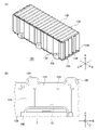
- FIG. 1 is a perspective view of a power storage device
- FIG. 2A is a schematic diagram of the power storage device viewed from the axial direction.
- FIG. 2B is a schematic diagram of the power storage device viewed from the second direction.
- 3A to 3E are process diagrams of a method for manufacturing a power storage device.
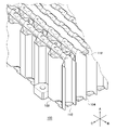
- 1 is a perspective view of a power storage module according to an embodiment;
- FIG. 1 is an exploded perspective view of an electricity storage module;
- FIG. FIG. 4 is a perspective view of a power storage device and holders arranged in a second direction;
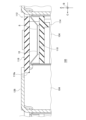
- 7A and 7B are cross-sectional views along planes perpendicular to the axial direction of a portion of the power storage module.
- FIG. 8(A) is an enlarged view of a portion of the filler.
- FIG. 8(B) is an enlarged view of the dashed line area in FIG. 7(A).
- FIG. 9A is a perspective view of part of the holder.
- FIG. 9B is a plan view of part of the holder.
- FIG. 10A is a perspective view of a power storage module.
- FIG. 10B is a cross-sectional view along a plane perpendicular to the second direction of part of the power storage module.
- 1 is a perspective view of a portion of an electricity storage module;
- FIGS. 12A and 12B are perspective views of a portion of the power storage module.
- FIG. 4 is a cross-sectional view along a plane perpendicular to the first direction of part of the power storage module;
- FIG. 1 is a perspective view of a power storage device 1.
- FIG. FIG. 2A is a schematic diagram of the power storage device 1 viewed from the axial direction A.
- FIG. 2B is a schematic diagram of the power storage device 1 viewed from the second direction C.
- FIG. 2B the inside of the film outer packaging 4 is also illustrated for convenience of explanation.
- the axial direction A is the direction in which the spiral axis of the electrode assembly 2 (the central axis of the cylinder) extends
- the first direction B is the direction in which the plurality of electrode assemblies 2 are arranged.
- a direction crossing the first direction B is defined as a second direction C.
- the axial direction A, the first direction B and the second direction C are orthogonal to each other.
- the power storage device 1 of the present embodiment is, for example, a rechargeable secondary battery such as a lithium ion battery, a nickel-hydrogen battery, or a nickel-cadmium battery, or a capacitor such as an electric double layer capacitor.
- a power storage device 1 has a plurality of electrode bodies 2 and a film exterior body 4 .
- power storage device 1 of the present embodiment includes eight electrode bodies 2, the number is not particularly limited and may be one or more.
- Each electrode body 2 is cylindrical, and has a spirally wound structure in which a strip-shaped first electrode plate and a strip-shaped second electrode plate are laminated with an inter-electrode separator sandwiched therebetween.
- the first electrode plate is a negative plate and the second electrode plate is a positive plate.
- the power storage device 1 has a plurality of electrode leads electrically connected to each electrode body 2 .
- the first electrode lead 8 is electrically connected to the first electrode plate.
- a second electrode lead 10 is electrically connected to the second electrode plate.
- the first electrode lead 8 and the second electrode lead 10 are belt-shaped (rectangular long in one direction), and one end of each is welded to each electrode plate.
- the plurality of electrode bodies 2 are arranged in the first direction B with predetermined intervals, with the postures determined so that the axial directions A of the electrode bodies 2 are parallel to each other.
- a plurality of electrode bodies 2 are wrapped in a common film exterior body 4 .
- the film outer body 4 has a structure in which, for example, two laminate films are laminated.
- Each laminate film has a structure in which thermoplastic resin sheets are laminated on both sides of a metal sheet such as an aluminum sheet.
- the film outer body 4 has a plurality of housing portions 12 and a sealing portion 14 .
- the plurality of accommodating portions 12 are arranged in the first direction B at predetermined intervals.
- Each accommodating portion 12 is cylindrical and individually wraps and accommodates each electrode body 2 .
- Each housing portion 12 is configured by a bag portion provided in the film outer packaging 4 .
- the bag portion is the portion where the two laminate films are separated from each other.
- each accommodating portion 12 protrudes in the thickness direction (second direction C) of the film outer packaging 4 from the sealing portion 14 along the shape of the side surface of the electrode body 2 .
- Each accommodating portion 12 accommodates an electrolyte solution 16 together with the electrode assembly 2 .
- the sealing portion 14 surrounds the outer periphery of each housing portion 12 to seal each housing portion 12 .
- the sealing portion 14 is composed of, for example, a welded portion of a thermoplastic resin sheet.
- the welded portion is obtained by subjecting the outer periphery of the bag portion of the film outer body 4 to thermocompression bonding, and welding the thermoplastic resin sheets of the two laminated films together.
- the sealing portion 14 seals each housing portion 12 and connects the plurality of housing portions 12 to each other.
- the sealing portion 14 includes a pair of first portions 14a arranged in the axial direction A with the accommodating portions 12 interposed therebetween and extending in the first direction B, and a plurality of accommodating portions 12 alternately arranged in the first direction B and axially extending.
- Each accommodating portion 12 has an end portion in the axial direction A sealed by a pair of first portions 14a, and an end portion in a first direction B by a pair of second portions 14b.
- One or more sealing portions 14 may be provided in accordance with the number of accommodating portions 12 .
- first electrode lead 8 and the second electrode lead 10 opposite to the side connected to the electrode body 2 protrude from the sealing portion 14 to the outside.
- the interface between each electrode lead and the film sheath 4 is sealed with a known sealant.
- the first electrode lead 8 and the second electrode lead 10 connected to each electrode body 2 protrude in opposite directions in the axial direction A. As shown in FIG. Moreover, each first electrode lead 8 protrudes to the same side.
- FIG. 3A is a first laminate film 20a is prepared.
- a plurality of semi-cylindrical depressions 18 are formed in advance in the first laminate film 20a.
- the plurality of depressions 18 are formed, for example, by subjecting the first laminate film 20a to a known process such as press working.
- An electrode body 2 is placed in each recess 18 .
- a first electrode lead 8 and a second electrode lead 10 are connected in advance to the electrode body 2 .
- a sealant (not shown) is provided on the first electrode lead 8 and the second electrode lead 10 .
- the second laminate film 20b is overlaid on the first laminate film 20a to form the film outer body 4.
- Semi-cylindrical depressions 18 are provided in the second laminate film 20b at positions facing the depressions 18 of the first laminate film 20a. Therefore, the accommodating portion 12 is formed by the pair of depressions 18 by overlapping the first laminate film 20a and the second laminate film 20b.
- the method of forming the depressions 18 in the second laminate film 20b is the same as the method of forming the depressions 18 in the first laminate film 20a.
- the tip of the first electrode lead 8 and the tip of the second electrode lead 10 protrude outside the film sheath 4 while the electrode assembly 2 is accommodated in the accommodation portion 12 .
- a portion of the film outer body 4 is subjected to a thermocompression bonding process to form a welded portion 22 .
- a non-welding portion 24 is a portion of the film outer casing 4 that is not subjected to the thermocompression bonding process.
- the non-welded portion 24 is arranged so as to connect each accommodation portion 12 and the outside of the film outer package 4 .
- a non-welded portion 24 is provided so as to connect the side from which the first electrode lead 8 protrudes out of the four sides of each accommodating portion 12 to the outside of the film outer package 4 .
- the remaining three sides of each accommodating portion 12 are surrounded by the welded portion 22 .
- the interface between the film outer package 4 and the second electrode lead 10 is sealed with a sealant.
- the electrolytic solution 16 is injected into each housing portion 12 through the non-welded portion 24 .
- the non-welding portion 24 is also subjected to thermocompression bonding as shown in FIG. 3(E).
- a sealing portion 14 surrounding the entire periphery of each accommodating portion 12 is formed.
- the interface between the film outer package 4 and the first electrode lead 8 is sealed with a sealant.
- the power storage device 1 is obtained through the above steps.
- each electrode body 2 may be wrapped by using one laminate film having a length twice as long as that of the power storage device 1 and folding this laminate film in half.
- the step of injecting the electrolytic solution 16 shown in FIG. can.
- the sealing portion 14 is formed by performing thermocompression bonding on the entire periphery of each accommodating portion 12 .
- the power storage device 1 is incorporated in the power storage module 100 according to the present embodiment.
- FIG. 4 is a perspective view of the power storage module 100 according to the embodiment.
- FIG. 5 is an exploded perspective view of the power storage module 100.
- FIG. 4 and 5 illustration of the reinforcing plate 128 is omitted.
- the power storage module 100 includes a power storage device 1 and a holder 104 .
- a power storage module 100 according to the present embodiment includes a plurality of power storage devices 1 and a plurality of holders 104 .
- the illustrated power storage module 100 includes eight power storage devices 1, the number is not particularly limited.
- the plurality of power storage devices 1 are arranged in the second direction C with the accommodating portions 12 aligned in the first direction B.
- Two power storage devices 1 adjacent in the second direction C are arranged such that the axial center of the electrode assembly 2 of the other power storage device 1 is positioned between the axial centers of two adjacent electrode bodies 2 of one power storage device 1 . , are displaced in the first direction B from each other. That is, the accommodation portion 12 of the other power storage device 1 is fitted between the valleys of the two accommodation portions 12 of the one power storage device 1 . Thereby, the dimension of the power storage module 100 in the second direction C can be reduced.
- the plurality of holders 104 are alternately arranged in the second direction C with the plurality of power storage devices 1 .
- the holder 104 extends in the first direction B (that is, it is long in the first direction B).
- power storage device 1 is held by holder 104 .
- the holder 104 as an example is made of metal such as aluminum, an aluminum alloy, or steel. This allows the holder 104 to have desired rigidity and thermal conductivity. It should be noted that the holder 104 may be made of resin as long as predetermined rigidity and thermal conductivity can be obtained.
- Power storage module 100 also includes filler 106 interposed between power storage device 1 and holder 104 . Filler 106 will be described in detail later.
- the power storage module 100 also includes a pair of end plates 108 .
- a plurality of power storage devices 1 and a plurality of holders 104 alternately stacked in second direction C are bound by a pair of end plates 108 .
- the power storage module 100 is fixed to a battery pack (not shown) through end plates 108 by screw fastening or the like.
- the power storage module 100 also includes a bus bar 110 (collector plate) that electrically connects a plurality of electrode leads.
- bus bar 110 collector plate
- the manner of electrical connection of each electrode body 2 and the manner of electrical connection of each power storage device 1 are not particularly limited.
- the plurality of electrode bodies 2 may be connected in series, may be connected in parallel, or may be connected in series and in parallel.
- the plurality of power storage devices 1 may be connected in series, may be connected in parallel, or may be connected in series and in parallel.
- the power storage module 100 also includes a plurality of insulating members 112 extending in the first direction B.
- Each insulating member 112 has a support plate 114 and a lid portion 116 .
- Support plate 114 and lid portion 116 extend in first direction B, respectively.
- Bus bar 110 is wrapped by support plate 114 and lid portion 116 .
- the insulating member 112 will be described later in detail.
- FIG. 6 is a perspective view of power storage device 1 and holder 104 arranged in second direction C.
- FIG. 7A and 7B are cross-sectional views along a plane perpendicular to the axial direction A of a portion of power storage module 100.
- FIG. 8A is an enlarged view of a portion of filler 106.
- FIG. 8(B) is an enlarged view of the dashed line area in FIG. 7(A). 7(A), 7(B), and 8(B) omit the illustration of the interior of the accommodating portion 12. As shown in FIG.
- the holder 104 of this embodiment has a plate shape extending in the first direction B.
- the holder 104 has a plurality of recesses 118 aligned in the first direction B and a plurality of flat portions 120 connecting adjacent recesses 118 .
- the holder 104 of the present embodiment has a corrugated plate shape that repeats unevenness in the first direction B. As shown in FIG. That is, the plurality of concave portions 118 and the plurality of flat portions 120 are arranged alternately in the first direction B when viewed from either main surface side. Further, the flat portion 120 on one main surface side constitutes the bottom portion 118a (see FIG. 7A, etc.) of the recessed portion 118 on the other main surface side.
- the holder 104 having such a structure can be formed, for example, by pressing a single metal plate.
- the holder 104 may be a plate material having a thickness such that the bottom portion 118a of the recessed portion 118 on one main surface side does not protrude further toward the other main surface side than the bottom portion 118a of the recessed portion 118 on the other main surface side. good. That is, in the thickness direction (second direction C) of holder 104, even if the extension range of recess 118 provided on one main surface and the extension range of recess 118 provided on the other main surface do not overlap, good.
- Each recess 118 has a groove shape elongated in the axial direction A. As shown in FIG. Filler 106 is applied to the wall surface of each recess 118 before power storage device 1 and holder 104 are assembled. When power storage device 1 and holder 104 are assembled, each accommodating portion 12 is fitted into each recess 118 . As a result, as shown in FIGS. 7A and 7B, the filler 106 is crushed and deformed by the accommodating portion 12 and the recessed portion 118 and spreads over the gap between the accommodating portion 12 and the recessed portion 118 .
- the distance between the concave portion 118 whose inner surface is composed of a plurality of flat surfaces, specifically a bottom portion 118a and a pair of inclined portions 118b described later, and the accommodating portion 12 having a substantially circular cross section varies depending on the location.
- the boundary portion between the bottom portion 118a and the inclined portion 118b is the farthest from the accommodating portion 12.
- the filler 106 is arranged at least between the boundary between the bottom portion 118 a and the slope portion 118 b and the containing portion 12 . This boundary portion can be filled with more filler 106 than other portions.
- the filling amount of the filler 106 can be locally increased without increasing the space of the recess 118 more than necessary. . Thereby, the heat absorption of the power storage device 1 can be efficiently performed.
- the filler 106 may be interposed between the flat portion 120 and the sealing portion 14, more specifically between the flat portion 120 and the second portion 14b. With this configuration, the filling amount of the filler 106 between the pair of holders 104 can be increased. Further, when filler 106 has adhesiveness, it is possible to increase the fixing strength between power storage device 1 and holder 104 .
- the filler 106 may cover the end surface of the accommodating portion 12 in the axial direction A. As shown in FIG. The filler 106 covering the end surface of the housing portion 12 can protect the end surface of the housing portion 12 from jets such as gas and flame jetted from other power storage devices 1 .
- the filler 106 of this embodiment has thixotropy.
- the thixotropy refers to a property in which the viscosity decreases and becomes liquid when subjected to stress, and the viscosity increases and becomes solid when allowed to stand still.
- the filler 106 preferably has a compounding initial viscosity (or initial viscosity) of 10,000 mPa ⁇ s or more. Since filler 106 has thixotropic properties, filler 106 can easily maintain its shape on the wall surface of recess 118 before power storage device 1 and holder 104 are assembled. This prevents the filler 106 from dripping down from the recess 118 . On the other hand, when power storage device 1 and holder 104 are assembled, filler 106 is stressed and easily deformed. This makes it easier to fill the space between the container 12 and the recess 118 with the filler 106 .
- the filler 106 has a property that the thermal conductivity at the first temperature is lower than the thermal conductivity at the second temperature, which is lower than the first temperature. That is, the thermal conductivity of the filler 106 decreases as the temperature rises.
- the first temperature is, for example, the temperature when each electrode body 2 falls into an abnormal state, and is, for example, 100° C. or higher.
- the second temperature is, for example, the temperature when each electrode body 2 is in a normal state, in other words, the temperature when the charging/discharging state of each electrode body 2 is within the design range. be.
- the thermal conductivity of filler 106 at the first temperature is preferably 0.1 W/mK or less, and the thermal conductivity of filler 106 at the second temperature is preferably 0.5 W/mK. That's it. Moreover, the difference between the thermal conductivity at the first temperature and the thermal conductivity at the second temperature is preferably 0.5 W/m ⁇ K or more.
- the first temperature, the second temperature, and the thermal conductivity at each temperature can be appropriately set based on experiments, simulations, or the like by a designer.
- each electrode body 2 When each electrode body 2 is in a normal state and the filler 106 is at the second temperature, as shown in FIG. facilitates heat transfer.
- the thermal conductivity of holder 104 is higher than the thermal conductivity of filler 106 at the second temperature.
- the thermal conductivity of filler 106 decreases reversibly. Note that the filler 106 that has reached the first temperature may have some heat transfer properties. In this case, the heat of the electrode body 2 in the abnormal state can be dissipated via the holder 104 .
- Examples of the component of the filler 106 which has thixotropic properties while changing its thermal conductivity depending on the temperature, include urethane or silicon as a main component and a metal hydroxide blended therein.
- the metal hydroxide is desirably contained in a mass ratio of 50% or more and 90% or less with respect to the total mass of the materials constituting the filler 106 .
- Metal hydroxides release water vapor by thermal decomposition when exposed to high temperatures. As a result, the metal hydroxide exerts an endothermic action and changes into a metal oxide having heat resistance and insulating properties.
- the main material such as urethane or silicon
- a porous structure of metal oxide is formed, exhibiting a heat insulating effect. That is, thermal conductivity is greatly reduced. It is conceivable that the battery may be heated to 800° C. or higher due to thermal runaway, but the formed porous metal oxide can maintain heat insulation even at such high temperatures.
- Such metal hydroxides include aluminum hydroxide (Al(OH) 3 ), magnesium hydroxide (Mg(OH) 2 ), calcium hydroxide (Ca(OH) 2 ), zinc hydroxide (Zn(OH ) 2 ), iron hydroxide (Fe(OH) 2 ), manganese hydroxide (Mn(OH) 2 ), zirconium hydroxide (Zr(OH) 2 ), gallium hydroxide (Ga(OH) 3 ).
- Al(OH) 3 magnesium hydroxide
- Ca(OH) 2 calcium hydroxide
- Zn(OH ) 2 zinc hydroxide
- Fe(OH) 2 iron hydroxide
- Mn(OH) 2 manganese hydroxide
- Zr(OH) 2 zirconium hydroxide
- gallium hydroxide Ga(OH) 3
- aluminum hydroxide is dehydrated and decomposed at 200° C. or higher to decompose into approximately 66% Al 2 O 3 and approximately 34% water vapor, exhibiting an endothermic reaction.
- This reaction absorbs the heat generated by the thermally runaway battery cell, making it possible to reduce the amount of heat transferred to the holder 104 .
- the main material decomposes and volatilizes at a high temperature, so that the porous aluminum oxide exhibits a heat insulating effect.
- the filler 106 of the present embodiment may contain a plurality of hollow glass beads 122.
- Hollow glass beads 122 are more flame resistant than the constituent material of filler 106 . Therefore, even if the constituent material of the filler 106 is destroyed by fire, the hollow glass beads 122 tend to remain between the accommodating portion 12 and the recess 118 . The remaining hollow glass beads 122 can prevent the thermal connection between the holder 104 and the accommodating portion 12 of the electrode assembly 2 in an abnormal state. Moreover, since it is hollow, the hollow glass beads 122 are light. Therefore, the weight of the power storage module 100 can be reduced.
- each flat portion 120 extends parallel to the sealing portion 14 .
- An adhesive 124 is applied to each flat portion 120 before power storage device 1 and holder 104 are assembled.
- the adhesive 124 a known insulating adhesive or the like can be used.
- each second portion 14b of sealing portion 14 and each flat portion 120 are pressed against each other.
- the adhesive 124 is crushed and deformed by the second portion 14b and the flat portion 120, and a layer of the adhesive 124 is formed between the second portion 14b and the flat portion 120. It is formed.
- Holder 104 is bonded to sealing portion 14 with adhesive 124 to hold power storage device 1 . Thereby, the rigidity of the power storage device 1 can be increased.
- each second portion 14 b is sandwiched in the second direction C by a pair of flat portions 120 .
- each flat portion 120 is adhered to the second portion 14b with an adhesive 124.
- the adhesive 124 also preferably has thixotropic properties like the filler 106 .
- the adhesive 124 may also have the property of decreasing thermal conductivity as the temperature rises, similar to the filler 106 .
- each recess 118 of this embodiment has a trapezoidal columnar shape, in other words, a cross section perpendicular to the axial direction A has a trapezoidal shape. That is, each recess 118 has a bottom portion 118a extending in the first direction B and a pair of inclined portions 118b extending obliquely from both ends of the bottom portion 118a in the first direction B. As shown in FIG. Since the pair of inclined portions 118b have the same length and the same angle with respect to the bottom portion 118a, each recessed portion 118 has the shape of an isosceles trapezoidal column.
- each inclined portion 118 b opposite to the bottom portion 118 a is connected to the flat portion 120 . Therefore, each inclined portion 118 b connects the bottom portion 118 a and the flat portion 120 .
- Two holders 104 adjacent in the second direction C are stacked such that the internal spaces of the recesses 118 face each other. As a result, a plurality of hexagonal prism-shaped spaces surrounding each housing portion 12 are formed.
- the power storage module 100 has a honeycomb structure in which a plurality of hexagonal columnar spaces are arranged. Thereby, the rigidity of the power storage module 100 can be further increased.
- FIG. 9A is a perspective view of part of the holder 104.
- FIG. FIG. 9B is a plan view of part of the holder 104.
- FIG. FIG. 10A is a perspective view of the power storage module 100.
- FIG. FIG. 10B is a cross-sectional view along a plane perpendicular to the second direction C of a portion of the power storage module 100.
- the holder 104 of this embodiment has a plurality of claws 126 at the ends in the axial direction A of the holder 104 .
- Each claw portion 126 bends toward the adjacent power storage device 1 and extends in a direction intersecting the axial direction A.
- Each claw portion 126 closes the end portion in the axial direction A in the internal space of the recessed portion 118 .
- the holder 104 of this embodiment has a claw portion 126 only at one end in the axial direction A (see FIG. 6).
- the postures of the two adjacent holders 104 are determined such that the end portions where the claw portions 126 are provided are opposite to each other. Therefore, when power storage module 100 is viewed from axial direction A, a plurality of rows of claw portions 126 extending in first direction B are arranged in second direction C at intervals.
- two claw portions 126 having different shapes are provided for one concave portion 118, but the configuration is not limited to this.
- Three or more claw portions 126 may be provided for one concave portion 118 .
- a claw portion 126 having the same shape as or a similar shape to the shape of the recessed portion 118 when viewed from the axial direction A may be provided.
- a notch may be provided at the bent portion of the holder 104 , such as the boundary between the bottom portion 118 a and the inclined portion 118 b or the boundary between the concave portion 118 and the claw portion 126 . This notch facilitates the processing for forming the bottom portion 118 a and the inclined portion 118 b and the processing for forming the claw portion 126 .
- the power storage module 100 of the present embodiment includes a pair of reinforcing plates 128.
- the reinforcing plate 128 is made of metal such as aluminum, aluminum alloy, or steel; thermoplastic resin such as polypropylene (PP), polybutylene terephthalate (PBT), polycarbonate (PC), Noryl (registered trademark) resin (modified PPE) made of fiber reinforced plastics (FRP) including carbon fiber reinforced plastics (CFRP) and glass fiber reinforced plastics (GFRP);
- a pair of reinforcing plates 128 sandwich in the axial direction A a laminate composed of a plurality of power storage devices 1, a plurality of holders 104, and a pair of end plates .
- Each end plate 108 can be secured to the stack by known securing means.
- the reinforcing plate 128 is thereby directly or indirectly connected to the plurality of holders 104 .
- the reinforcing plate 128 of this embodiment is supported by a plurality of claw portions 126 . That is, the claw portion 126 is used as a support structure for the reinforcing plate 128 .
- the reinforcing plate 128 of this embodiment has a plurality of ribs 130 arranged in the first direction B at predetermined intervals.
- Each rib 130 is provided on the main surface of reinforcing plate 128 facing away from the stack and extends in the stacking direction of power storage device 1 and holder 104, that is, second direction C. As shown in FIG. A groove extending in the second direction C is provided on the surface of each rib 130 facing the laminate side.
- the rigidity of the power storage module 100 can be increased. Further, by transferring the heat of each power storage device 1 to reinforcing plate 128, each power storage device 1 can be cooled. In addition, by connecting or incorporating a cooling pipe to reinforcing plate 128, the cooling efficiency of power storage device 1 can be further enhanced. In addition, when the temperature of the electrode body 2 rises excessively and gas is ejected from the housing portion 12 or flame is generated by this gas, diffusion of the gas and flame can be suppressed. Accordingly, it is possible to suppress the spread of fire to other housing portions 12 .
- the reinforcing plate 128 since the reinforcing plate 128 has the ribs 130, the rigidity of the reinforcing plate 128 and thus the power storage module 100 can be further increased. Moreover, the grooves provided in the ribs 130 can also function as ducts through which the gas ejected from each housing portion 12 flows. In addition, the reinforcing plate 128 may be only one sheet, and the rib 130 may not be provided.
- Diffusion of gas and flame ejected from the housing portion 12 is also suppressed by the claw portion 126 . That is, diffusion of the gas or flame is suppressed by the claw portion 126 that overlaps with the containing portion 12 that ejects the gas or flame in the axial direction A. As shown in FIG.
- the reinforcing plate 128 is not provided, the gas or flame ejected from the housing portion 12 passes through the gaps of the claw portions 126 or crushes the claw portions 126 and reaches the battery pack (not shown). can. When this gas or flame hits the battery pack and bounces back, the bounced gas or flame can be prevented from reaching the other storage portion 12 by the claw portion 126 overlapping the other storage portion 12 in the axial direction A. .
- FIG. 11 illustrates a state in which a part of the insulating member 112 is removed.
- FIG. 12A illustrates a state in which the lid portion 116 is removed.
- the power storage module 100 includes the insulating member 112 as described above.
- the insulating member 112 has a support plate 114 and a lid portion 116 . As shown in FIG. 11, the insulating member 112 is placed on the end of the holder 104 on the side without the claw portion 126 . Therefore, when power storage module 100 is viewed from axial direction A, rows of claw portions 126 extending in first direction B and insulating members 112 are alternately arranged in second direction C. As shown in FIG.
- the insulating member 112 is made of resin having insulating properties, for example.
- Thermoplastic resins such as polypropylene (PP), polybutylene terephthalate (PBT), polycarbonate (PC), Noryl (registered trademark) resin (modified PPE), etc.; carbon fiber reinforced plastic (CFRP). Fiber reinforced plastics (FRP) including glass fiber reinforced plastics (GFRP) and the like are exemplified.
- the support plate 114 is first placed on the holder 104 .
- Bus bar 110 is mounted on support plate 114 .
- the electrode leads of the two power storage devices 1 arranged with the bus bar 110 interposed therebetween when viewed in the axial direction A are joined to the bus bar 110 on the support plate 114 .
- the lid portion 116 is attached to the support plate 114 .
- bus bar 110 on support plate 114 is covered with lid portion 116 .
- the lid portion 116 is fixed to the support plate 114 by a known fixing method such as lance engagement.
- the lid portion 116 has a plurality of projecting portions 116 a projecting toward the holder 104 side, more specifically, toward the inner space of the recess portion 118 when viewed from the axial direction A. As shown in FIG.
- the insulating member 112 is interposed between the multiple electrode leads and the holder 104 .
- the support plate 114 is interposed between the holder 104 on which the insulating member 112 is placed and the first electrode lead 8 and the second electrode lead 10 .
- Support plate 114 is also interposed between holder 104 and bus bar 110 .
- the projecting portion 116a of the lid portion 116 enters below the claw portion 126 of the holder 104 adjacent to the holder 104 on which the insulating member 112 is placed. Thereby, the lid portion 116 is interposed between the claw portion 126 and the first electrode lead 8 and the second electrode lead 10 .
- Lid portion 116 is also interposed between claw portion 126 and bus bar 110 . With these, electrical connection between the electrode lead/bus bar 110 and the holder 104 can be suppressed, that is, insulation can be achieved.
- the projecting portion 116 a and the claw portion 126 also have the function of blocking the gas and flame ejected from the housing portion 12 .
- power storage module 100 includes holder 104 that holds power storage device 1 .
- the rigidity of the power storage module 100 can be increased.
- each electrode body 2 can be cooled by the heat absorbing action of the holder 104 .
- power storage module 100 includes filler 106 interposed between power storage device 1 and holder 104 .
- filler 106 By filling the gap between power storage device 1 and holder 104 with filler 106 , heat transfer from each electrode assembly 2 to holder 104 can be promoted.
- each electrode assembly 2 can be cooled by the endothermic action of the filler 106 itself.
- the posture of power storage device 1 can be further stabilized. Therefore, the electrical connection state between each power storage device 1 and bus bar 110 can be more stably maintained, and breakage of each power storage device 1 can be further suppressed. Therefore, power generation performance and safety of the power storage module 100 can be enhanced.
- the filler 106 has the property of decreasing thermal conductivity as the temperature rises. Thereby, when each electrode body 2 is in a normal state, the heat of each electrode body 2 can be actively transferred to the holder 104 via the filler 106 . As a result, the temperature deviation between the electrode bodies 2 can be reduced in the power storage module 100 as a whole. Further, when each electrode body 2 falls into an abnormal state and reaches the first temperature, the filler 106 can suppress heat transfer from each electrode body 2 to the holder 104 . As a result, it is possible to suppress the thermal runaway of the electrode body 2 from spreading to other electrode bodies 2 in a chain reaction.
- Holder 104 is not limited to holding power storage device 1 in which a plurality of electrode bodies 2 are sealed with film package 4 . Even in such a case, the effect of the filler 106 described above can be enjoyed.
- the filler 106 of this embodiment contains hollow glass beads 122 . This makes it possible to reduce the weight of the filler 106 and thus the weight of the power storage module 100 . In addition, it is possible to easily maintain the heat insulating effect of the filler 106 when the electrode body 2 falls into an abnormal state. In addition, filler 106 of the present embodiment has thixotropy. This makes it possible to improve the ease of assembly of the power storage module 100 . In addition, reliability and yield in manufacturing the power storage module 100 can be improved.
- the power storage device 1 of the present embodiment has a pouch structure in which a plurality of electrode bodies 2 are housed in the film exterior body 4 .
- the weight of the electric storage module 100 can be reduced as compared with the case where each electrode body 2 is individually sealed with an outer can.
- the number of electrode bodies 2 and accommodating portions 12 included in power storage device 1 may be one.
- Holder 104 of the present embodiment holds power storage device 1 by being adhered to sealing portion 14 of power storage device 1 .
- Power storage device 1 is long in first direction B, and film exterior body 4 is highly flexible. Therefore, power storage device 1 is easily bent.
- by adhering the holder 104 to the sealing portion 14 it becomes possible to hold the power storage device 1 more stably.
- the rigidity of the power storage module 100 can be enhanced, and thus the safety of the power storage module 100 can be enhanced.
- this improvement in rigidity makes it easier to reduce the thickness of the holder 104, so further weight reduction of the power storage module 100 can be expected.
- the holders 104 are adhered to both sides of the sealing portion 14 . Thereby, the rigidity of the power storage module 100 can be further improved. Further, in the present embodiment, the hexagonal columnar spaces for accommodating the respective accommodating portions 12 are laid out to form a honeycomb-shaped power storage device holding structure. Thereby, the rigidity of the power storage module 100 can be further improved.
- the holder 104 of the present embodiment has a plurality of claw portions 126, and when viewed from the axial direction A, each hexagonal columnar space is partially closed by the claw portions 126.
- power storage module 100 of the present embodiment includes reinforcing plate 128 connected to holder 104 . As a result, it is possible to improve the rigidity of the power storage module 100 and improve the heat dissipation of each power storage device 1 . Furthermore, when gas or flame blows out from each containing portion 12, the spread of fire to other containing portions 12 can be suppressed.
- power storage module 100 of the present embodiment includes insulating member 112 interposed between the plurality of electrode leads and holder 104 .
- insulating member 112 interposed between the plurality of electrode leads and holder 104 .
- bus bar 110 is placed on support plate 114 and covered with lid portion 116 .
- insulating member 112 is used as a supporting member for bus bar 110, the number of components of power storage module 100 can be reduced.
- a power storage device (1) a power storage device (1); A holder (104) that holds the power storage device (1), A power storage device (1) is a film exterior having a cylindrical electrode body (2), a housing portion (12) that wraps the electrode body (2), and a sealing portion (14) that seals the housing portion (12). a body (4); the holder (104) is glued to the seal (14); A power storage module (100).
- a power storage device (1) has a plurality of electrode bodies (2) and a plurality of housing portions (12) individually wrapping the plurality of electrode bodies (2), The sealing portion (14) seals each housing portion (12) and connects the plurality of housing portions (12) to each other, The storage module (100) according to item 1.
- (Item 3) a plurality of power storage devices (1) arranged in a first direction (B) in which the plurality of electrode bodies (2) are arranged and a second direction (C) intersecting with an axial direction (A) of the electrode bodies (2); comprising a plurality of power storage devices (1) and a plurality of holders (104) alternately arranged in the second direction (C), Two holders (104) adjacent to each other sandwich the sealing portion (14) and are each adhered to the sealing portion (14). 3.
- the storage module (100) according to item 2.
- Each holder (104) has a plate-like shape extending in the first direction (B), and includes a plurality of trapezoidal column-shaped recesses (118) aligned in the first direction (B) and into which the storage portions (12) are fitted. a plurality of flats (120) bridging the mating recesses (118) and adhered to the seal (14);
- the electricity storage module (100) has a honeycomb structure in which a plurality of hexagonal prism-shaped spaces surrounding the housing portion (12) are arranged. 4.
- the storage module (100) according to item 3. (Item 5)
- the holder (104) has a plurality of claws (126) bent toward the adjacent power storage device (1) at the end of the electrode body (2) in the axial direction (A). 5.
- the storage module (100) according to any one of items 1 to 4.
- (Item 6) When viewed from the axial direction (A), the claw (126) overlaps with the housing (12), 6.
- (Item 7) a reinforcing plate (128) connected to the holder (104); 7.
- (Item 8) The reinforcing plate (128) has ribs (130) extending in the stacking direction (C) of the power storage device (1) and the holder (104), The storage module (100) according to item 7.
- a power storage device (1) has a plurality of electrode bodies (2) and a plurality of electrode leads (8, 10) electrically connected to each electrode body (2) and protruding from a sealing portion (14). death,
- the power storage module (100) comprises an insulating member (112) interposed between the plurality of electrode leads (8, 10) and the holder (104). 9.
- the storage module (100) according to any one of items 1-8.
- a bus bar (110) electrically connecting a plurality of electrode leads (8, 10)
- the insulating member (112) has a support plate (114) on which the busbar (110) is mounted, and a lid (116) that covers the busbar (110) on the support plate (114). 10.
- the storage module (100) according to item 9.
- the lid (116) has a plurality of protrusions (116a) that protrude toward the holder (104) when viewed from the axial direction (A) of the electrode assembly (2).
- a power storage module (100) according to item 10.
- (Item 12) a power storage device (1); a holder (104) holding the power storage device (1); a filler (106) interposed between the power storage device (1) and the holder (104) and having a lower thermal conductivity at a first temperature than at a second temperature lower than the first temperature;
- the thermal conductivity of the holder (104) is higher than the thermal conductivity of the filler (106) at the second temperature; 13.
- the storage module (100) according to item 12.
- the filler (106) contains hollow glass beads (122), 14.
- the filler (106) has thixotropy, 15.
- the power storage device (1) is a cylindrical electrode body (2); A film outer body (4) having a housing portion (12) that wraps the electrode body (2) and a sealing portion (14) that seals the housing portion (12), 16.
- the holder (104) is glued to the seal (14); 17.
- a power storage device (1) has a plurality of electrode bodies (2) and a plurality of housing portions (12) individually wrapping the plurality of electrode bodies (2), The sealing portion (14) seals each housing portion (12) and connects the plurality of housing portions (12) to each other, 18.
- the storage module (100) according to item 17.
- the filler (106) covers the end surface of the housing (12) in the axial direction (A) of the electrode body (2), 19.
- the storage module (100) according to any of items 16-18.
- the storage module (100) according to item 18.
- Each holder (104) has a plate-like shape extending in the first direction (B), and includes a plurality of trapezoidal column-shaped recesses (118) aligned in the first direction (B) and into which the storage portions (12) are fitted. a plurality of flats (120) bridging the mating recesses (118) and adhered to the seal (14);
- the electricity storage module (100) has a honeycomb structure in which a plurality of hexagonal prism-shaped spaces surrounding the housing portion (12) are arranged. 21.
- the recess (118) comprises a bottom (118a) and a ramp (118b) connecting the bottom (118a) and the flat (120);
- the filler (106) is disposed at least between the boundaries of the bottom (118a) and ramp (118b) and the reservoir (12); 22.
- the storage module (100) according to item 21. (Item 23) the filler (106) is interposed between the flat portion (120) and the seal portion (14); 23.
- the holder (104) has a plurality of claws (126) bent toward the adjacent power storage device (1) at the end of the electrode body (2) in the axial direction (A). 24.
- the storage module (100) according to any one of items 16-23.
- a power storage device (1) has a plurality of electrode bodies (2) and a plurality of electrode leads (8, 10) electrically connected to each electrode body (2) and protruding from a sealing portion (14).
- the power storage module (100) comprises an insulating member (112) interposed between the plurality of electrode leads (8, 10) and the holder (104). 28.
- the storage module (100) according to any one of items 16-27.
- (Item 29) A bus bar (110) electrically connecting a plurality of electrode leads (8, 10),
- the insulating member (112) has a support plate (114) on which the busbar (110) is mounted, and a lid (116) that covers the busbar (110) on the support plate (114). 29.
- the lid (116) has a plurality of protrusions (116a) that protrude toward the holder (104) when viewed from the axial direction (A) of the electrode assembly (2). 30.
- the present disclosure can be used for power storage modules.
- 1 power storage device 1 power storage device, 2 electrode body, 4 film outer body, 12 housing portion, 14 sealing portion, 100 power storage module, 104 holder, 106 filler, 110 bus bar, 112 insulating member, 114 support plate, 116 lid portion, 118 concave portion , 120 Flat portion, 122 Hollow glass beads, 124 Adhesive, 126 Claw portion, 128 Reinforcing plate.
Abstract
Description
まず、本実施の形態に係る蓄電モジュールが備える蓄電装置について説明する。図1は、蓄電装置1の斜視図である。図2(A)は、軸心方向Aから見た蓄電装置1の模式図である。図2(B)は、第2方向Cから見た蓄電装置1の模式図である。図2(B)では、説明の便宜上、フィルム外装体4の内部も図示している。本実施の形態では、電極体2の渦巻きの軸(円筒の中心軸)が延びる方向を軸心方向Aとし、複数の電極体2が並ぶ方向を第1方向Bとし、軸心方向Aおよび第1方向Bと交わる方向を第2方向Cとする。一例として、軸心方向A、第1方向Bおよび第2方向Cは、互いに直交する。 [Power storage device]
First, the power storage device included in the power storage module according to the present embodiment will be described. FIG. 1 is a perspective view of a
蓄電装置1は、本実施の形態に係る蓄電モジュール100に組み込まれる。図4は、実施の形態に係る蓄電モジュール100の斜視図である。図5は、蓄電モジュール100の分解斜視図である。なお、図4および図5では、補強板128の図示を省略している。蓄電モジュール100は、蓄電装置1と、ホルダ104とを備える。本実施の形態の蓄電モジュール100は、複数の蓄電装置1と、複数のホルダ104とを備える。なお、図示した蓄電モジュール100は8つの蓄電装置1を備えるが、その数は特に限定されない。 [Power storage module]
The
各凹部118は、軸心方向Aに長い溝状である。蓄電装置1およびホルダ104が組み付けられる前の状態で、各凹部118の壁面には充填剤106が塗布されている。蓄電装置1およびホルダ104が組み付けられると、各収容部12が各凹部118に嵌まる。これにより、図7(A)および図7(B)に示すように、充填剤106が収容部12および凹部118によって押し潰されて変形し、収容部12および凹部118の隙間に行き渡る。 [filler]
Each
図6に示すように、各平坦部120は封止部14に対して平行に延びる。蓄電装置1およびホルダ104が組み付けられる前の状態で、各平坦部120には接着剤124が塗布されている。接着剤124としては、公知の絶縁性接着剤等を用いることができる。蓄電装置1およびホルダ104が組み付けられると、封止部14の各第2部分14bと各平坦部120とが互いに押し付けられる。これにより、図8(B)に示すように、接着剤124が第2部分14bおよび平坦部120によって押し潰されて変形し、第2部分14bおよび平坦部120の間に接着剤124の層が形成される。ホルダ104は、接着剤124により封止部14に接着されて蓄電装置1を保持する。これにより、蓄電装置1の剛性を高めることができる。 [glue]
As shown in FIG. 6, each
図7(A)および図7(B)に示すように、本実施の形態の各凹部118は台形柱状、換言すれば軸心方向Aに直交する断面が台形状である。つまり各凹部118は、第1方向Bに延びる底部118aと、この底部118aの第1方向Bにおける両端から斜めに延びる一対の傾斜部118bとを有する。一対の傾斜部118bは、長さと底部118aに対する角度とが等しいため、各凹部118は等脚台形柱状である。各傾斜部118bにおける底部118aとは反対側の端部は、平坦部120に接続される。したがって、各傾斜部118bは、底部118aと平坦部120とを繋ぐ。第2方向Cで隣り合う2つのホルダ104は、それぞれの凹部118の内部空間が向かい合うようにして積層される。これにより、各収容部12を囲う六角柱状の空間が複数形成される。蓄電モジュール100は、六角柱状の複数の空間が配列されたハニカム構造を有する。これにより、蓄電モジュール100の剛性をさらに高めることができる。 [Honeycomb structure]
As shown in FIGS. 7A and 7B, each
図9(A)は、ホルダ104の一部分の斜視図である。図9(B)は、ホルダ104の一部分の平面図である。図10(A)は、蓄電モジュール100の斜視図である。図10(B)は、蓄電モジュール100の一部分の第2方向Cに垂直な平面に沿った断面図である。図9(A)および図9(B)に示すように、本実施の形態のホルダ104は、ホルダ104の軸心方向Aにおける端部に複数の爪部126を有する。各爪部126は、隣接する蓄電装置1側に折れ曲がって、軸心方向Aと交わる方向に延びる。各爪部126は、凹部118の内部空間における軸心方向Aの端部を塞ぐ。 [Claw portion and reinforcing plate]
FIG. 9A is a perspective view of part of the
図11、図12(A)および図12(B)は、蓄電モジュール100の一部分の斜視図である。図13は、蓄電モジュール100の一部分の第1方向Bに垂直な平面に沿った断面図である。なお、図11では、一部の絶縁部材112が取り除かれた状態を図示している。また、図12(A)では、蓋部116が取り除かれた状態を図示している。 [Insulating material]
11, 12A, and 12B are perspective views of a portion of
(項目1)
蓄電装置(1)と、
蓄電装置(1)を保持するホルダ(104)と、を備え、
蓄電装置(1)は、円筒形の電極体(2)と、電極体(2)を包む収容部(12)、および収容部(12)を封止する封止部(14)を有するフィルム外装体(4)と、を有し、
ホルダ(104)は、封止部(14)に接着される、
蓄電モジュール(100)。
(項目2)
蓄電装置(1)は、複数の電極体(2)と、複数の電極体(2)を個々に包む複数の収容部(12)と、を有し、
封止部(14)は、各収容部(12)を封止するとともに複数の収容部(12)を互いに連結する、
項目1に記載の蓄電モジュール(100)。
(項目3)
複数の電極体(2)が並ぶ第1方向(B)および電極体(2)の軸心方向(A)と交わる第2方向(C)に配列される複数の蓄電装置(1)と、
複数の蓄電装置(1)と第2方向(C)に交互に並ぶ複数のホルダ(104)と、を備え、
隣り合う2つのホルダ(104)は、封止部(14)を挟むとともに、それぞれが当該封止部(14)に接着される、
項目2に記載の蓄電モジュール(100)。
(項目4)
各ホルダ(104)は、第1方向(B)に延びる板状であり、第1方向(B)に並んで各収容部(12)が嵌まる複数の台形柱状の凹部(118)と、隣り合う凹部(118)をつなぐとともに封止部(14)に接着される複数の平坦部(120)と、を有し、
蓄電モジュール(100)は、収容部(12)を囲う六角柱状の空間が複数配列されたハニカム構造を有する、
項目3に記載の蓄電モジュール(100)。
(項目5)
ホルダ(104)は、電極体(2)の軸心方向(A)における端部に、隣接する蓄電装置(1)側に折れ曲がった複数の爪部(126)を有する、
項目1乃至4のいずれかに記載の蓄電モジュール(100)。
(項目6)
軸心方向(A)から見て、爪部(126)は、収容部(12)と重なる、
項目5に記載の蓄電モジュール(100)。
(項目7)
ホルダ(104)に接続される補強板(128)を備える、
項目1乃至6のいずれかに記載の蓄電モジュール(100)。
(項目8)
補強板(128)は、蓄電装置(1)およびホルダ(104)の積層方向(C)に延びるリブ(130)を有する、
項目7に記載の蓄電モジュール(100)。
(項目9)
蓄電装置(1)は、複数の電極体(2)と、各電極体(2)に電気的に接続されるとともに封止部(14)から突出する複数の電極リード(8,10)を有し、
蓄電モジュール(100)は、複数の電極リード(8,10)およびホルダ(104)の間に介在する絶縁部材(112)を備える、
項目1乃至8のいずれかに記載の蓄電モジュール(100)。
(項目10)
複数の電極リード(8,10)を電気的に接続するバスバー(110)を備え、
絶縁部材(112)は、バスバー(110)が載置される支持板(114)と、支持板(114)上のバスバー(110)を覆う蓋部(116)と、を有する、
項目9に記載の蓄電モジュール(100)。
(項目11)
蓋部(116)は、電極体(2)の軸心方向(A)から見てホルダ(104)側に突出する複数の突出部(116a)を有する、
項目10に記載の蓄電モジュール(100)。
(項目12)
蓄電装置(1)と、
蓄電装置(1)を保持するホルダ(104)と、
蓄電装置(1)およびホルダ(104)の間に介在し、第1温度における熱伝導率が第1温度よりも低い第2温度における熱伝導率よりも低い充填剤(106)と、を備える、
蓄電モジュール(100)。
(項目13)
ホルダ(104)の熱伝導率は、第2温度における充填剤(106)の熱伝導率よりも高い、
項目12に記載の蓄電モジュール(100)。
(項目14)
充填剤(106)は、中空ガラスビーズ(122)を含有する、
項目12または13に記載の蓄電モジュール(100)。
(項目15)
充填剤(106)は、チクソ性を有する、
項目12乃至14のいずれかに記載の蓄電モジュール(100)。
(項目16)
蓄電装置(1)は、
円筒形の電極体(2)と、
電極体(2)を包む収容部(12)、および収容部(12)を封止する封止部(14)を有するフィルム外装体(4)と、を有する、
項目12乃至15のいずれかに記載の蓄電モジュール(100)。
(項目17)
ホルダ(104)は、封止部(14)に接着される、
項目16に記載の蓄電モジュール(100)。
(項目18)
蓄電装置(1)は、複数の電極体(2)と、複数の電極体(2)を個々に包む複数の収容部(12)と、を有し、
封止部(14)は、各収容部(12)を封止するとともに複数の収容部(12)を互いに連結する、
項目17に記載の蓄電モジュール(100)。
(項目19)
充填剤(106)は、電極体(2)の軸心方向(A)における収容部(12)の端面を覆う、
項目16乃至18のいずれかに記載の蓄電モジュール(100)。
(項目20)
複数の電極体(2)が並ぶ第1方向(B)および電極体(2)の軸心方向(A)と交わる第2方向(C)に配列される複数の蓄電装置(1)と、
複数の蓄電装置(1)と第2方向(C)に交互に並ぶ複数のホルダ(104)と、を備え、
隣り合う2つのホルダ(104)は、封止部(14)を挟むとともに、それぞれが当該封止部(14)に接着される、
項目18に記載の蓄電モジュール(100)。
(項目21)
各ホルダ(104)は、第1方向(B)に延びる板状であり、第1方向(B)に並んで各収容部(12)が嵌まる複数の台形柱状の凹部(118)と、隣り合う凹部(118)をつなぐとともに封止部(14)に接着される複数の平坦部(120)と、を有し、
蓄電モジュール(100)は、収容部(12)を囲う六角柱状の空間が複数配列されたハニカム構造を有する、
項目20に記載の蓄電モジュール(100)。
(項目22)
凹部(118)は、底部(118a)と、底部(118a)および平坦部(120)を繋ぐ傾斜部(118b)と、を備え、
充填剤(106)は、少なくとも底部(118a)および傾斜部(118b)の境界と、収容部(12)との間に配置される、
項目21に記載の蓄電モジュール(100)。
(項目23)
充填剤(106)は、平坦部(120)と封止部(14)との間に介在する、
項目21または22に記載の蓄電モジュール(100)。
(項目24)
ホルダ(104)は、電極体(2)の軸心方向(A)における端部に、隣接する蓄電装置(1)側に折れ曲がった複数の爪部(126)を有する、
項目16乃至23のいずれかに記載の蓄電モジュール(100)。
(項目25)
軸心方向(A)から見て、爪部(126)は、収容部(12)と重なる、
項目24に記載の蓄電モジュール(100)。
(項目26)
ホルダ(104)に接続される補強板(128)を備える、
項目16乃至25のいずれかに記載の蓄電モジュール(100)。
(項目27)
補強板(128)は、蓄電装置(1)およびホルダ(104)の積層方向(C)に延びるリブ(130)を有する、
項目26に記載の蓄電モジュール(100)。
(項目28)
蓄電装置(1)は、複数の電極体(2)と、各電極体(2)に電気的に接続されるとともに封止部(14)から突出する複数の電極リード(8,10)を有し、
蓄電モジュール(100)は、複数の電極リード(8,10)およびホルダ(104)の間に介在する絶縁部材(112)を備える、
項目16乃至27のいずれかに記載の蓄電モジュール(100)。
(項目29)
複数の電極リード(8,10)を電気的に接続するバスバー(110)を備え、
絶縁部材(112)は、バスバー(110)が載置される支持板(114)と、支持板(114)上のバスバー(110)を覆う蓋部(116)と、を有する、
項目28に記載の蓄電モジュール(100)。
(項目30)
蓋部(116)は、電極体(2)の軸心方向(A)から見てホルダ(104)側に突出する複数の突出部(116a)を有する、
項目29に記載の蓄電モジュール(100)。 The invention according to the embodiment described above may be specified by the items described below.
(Item 1)
a power storage device (1);
A holder (104) that holds the power storage device (1),
A power storage device (1) is a film exterior having a cylindrical electrode body (2), a housing portion (12) that wraps the electrode body (2), and a sealing portion (14) that seals the housing portion (12). a body (4);
the holder (104) is glued to the seal (14);
A power storage module (100).
(Item 2)
A power storage device (1) has a plurality of electrode bodies (2) and a plurality of housing portions (12) individually wrapping the plurality of electrode bodies (2),
The sealing portion (14) seals each housing portion (12) and connects the plurality of housing portions (12) to each other,
The storage module (100) according to
(Item 3)
a plurality of power storage devices (1) arranged in a first direction (B) in which the plurality of electrode bodies (2) are arranged and a second direction (C) intersecting with an axial direction (A) of the electrode bodies (2);
comprising a plurality of power storage devices (1) and a plurality of holders (104) alternately arranged in the second direction (C),
Two holders (104) adjacent to each other sandwich the sealing portion (14) and are each adhered to the sealing portion (14).
3. The storage module (100) according to
(Item 4)
Each holder (104) has a plate-like shape extending in the first direction (B), and includes a plurality of trapezoidal column-shaped recesses (118) aligned in the first direction (B) and into which the storage portions (12) are fitted. a plurality of flats (120) bridging the mating recesses (118) and adhered to the seal (14);
The electricity storage module (100) has a honeycomb structure in which a plurality of hexagonal prism-shaped spaces surrounding the housing portion (12) are arranged.
4. The storage module (100) according to item 3.
(Item 5)
The holder (104) has a plurality of claws (126) bent toward the adjacent power storage device (1) at the end of the electrode body (2) in the axial direction (A).
5. The storage module (100) according to any one of
(Item 6)
When viewed from the axial direction (A), the claw (126) overlaps with the housing (12),
6. The storage module (100) according to item 5.
(Item 7)
a reinforcing plate (128) connected to the holder (104);
7. The storage module (100) according to any one of
(Item 8)
The reinforcing plate (128) has ribs (130) extending in the stacking direction (C) of the power storage device (1) and the holder (104),
The storage module (100) according to item 7.
(Item 9)
A power storage device (1) has a plurality of electrode bodies (2) and a plurality of electrode leads (8, 10) electrically connected to each electrode body (2) and protruding from a sealing portion (14). death,
The power storage module (100) comprises an insulating member (112) interposed between the plurality of electrode leads (8, 10) and the holder (104).
9. The storage module (100) according to any one of items 1-8.
(Item 10)
A bus bar (110) electrically connecting a plurality of electrode leads (8, 10),
The insulating member (112) has a support plate (114) on which the busbar (110) is mounted, and a lid (116) that covers the busbar (110) on the support plate (114).
10. The storage module (100) according to item 9.
(Item 11)
The lid (116) has a plurality of protrusions (116a) that protrude toward the holder (104) when viewed from the axial direction (A) of the electrode assembly (2).
11. A power storage module (100) according to
(Item 12)
a power storage device (1);
a holder (104) holding the power storage device (1);
a filler (106) interposed between the power storage device (1) and the holder (104) and having a lower thermal conductivity at a first temperature than at a second temperature lower than the first temperature;
A power storage module (100).
(Item 13)
the thermal conductivity of the holder (104) is higher than the thermal conductivity of the filler (106) at the second temperature;
13. The storage module (100) according to
(Item 14)
The filler (106) contains hollow glass beads (122),
14. The storage module (100) according to
(Item 15)
The filler (106) has thixotropy,
15. The storage module (100) according to any one of items 12-14.
(Item 16)
The power storage device (1) is
a cylindrical electrode body (2);
A film outer body (4) having a housing portion (12) that wraps the electrode body (2) and a sealing portion (14) that seals the housing portion (12),
16. The storage module (100) according to any one of items 12-15.
(Item 17)
the holder (104) is glued to the seal (14);
17. The storage module (100) according to
(Item 18)
A power storage device (1) has a plurality of electrode bodies (2) and a plurality of housing portions (12) individually wrapping the plurality of electrode bodies (2),
The sealing portion (14) seals each housing portion (12) and connects the plurality of housing portions (12) to each other,
18. The storage module (100) according to item 17.
(Item 19)
The filler (106) covers the end surface of the housing (12) in the axial direction (A) of the electrode body (2),
19. The storage module (100) according to any of items 16-18.
(Item 20)
a plurality of power storage devices (1) arranged in a first direction (B) in which the plurality of electrode bodies (2) are arranged and a second direction (C) intersecting with an axial direction (A) of the electrode bodies (2);
comprising a plurality of power storage devices (1) and a plurality of holders (104) alternately arranged in the second direction (C),
Two holders (104) adjacent to each other sandwich the sealing portion (14) and are each adhered to the sealing portion (14).
19. The storage module (100) according to
(Item 21)
Each holder (104) has a plate-like shape extending in the first direction (B), and includes a plurality of trapezoidal column-shaped recesses (118) aligned in the first direction (B) and into which the storage portions (12) are fitted. a plurality of flats (120) bridging the mating recesses (118) and adhered to the seal (14);
The electricity storage module (100) has a honeycomb structure in which a plurality of hexagonal prism-shaped spaces surrounding the housing portion (12) are arranged.
21. A power storage module (100) according to
(Item 22)
the recess (118) comprises a bottom (118a) and a ramp (118b) connecting the bottom (118a) and the flat (120);
The filler (106) is disposed at least between the boundaries of the bottom (118a) and ramp (118b) and the reservoir (12);
22. The storage module (100) according to item 21.
(Item 23)
the filler (106) is interposed between the flat portion (120) and the seal portion (14);
23. The storage module (100) according to
(Item 24)
The holder (104) has a plurality of claws (126) bent toward the adjacent power storage device (1) at the end of the electrode body (2) in the axial direction (A).
24. The storage module (100) according to any one of items 16-23.
(Item 25)
When viewed from the axial direction (A), the claw (126) overlaps with the housing (12),
25. The storage module (100) according to
(Item 26)
a reinforcing plate (128) connected to the holder (104);
26. The storage module (100) according to any one of items 16-25.
(Item 27)
The reinforcing plate (128) has ribs (130) extending in the stacking direction (C) of the power storage device (1) and the holder (104),
27. The storage module (100) according to item 26.
(Item 28)
A power storage device (1) has a plurality of electrode bodies (2) and a plurality of electrode leads (8, 10) electrically connected to each electrode body (2) and protruding from a sealing portion (14). death,
The power storage module (100) comprises an insulating member (112) interposed between the plurality of electrode leads (8, 10) and the holder (104).
28. The storage module (100) according to any one of items 16-27.
(Item 29)
A bus bar (110) electrically connecting a plurality of electrode leads (8, 10),
The insulating member (112) has a support plate (114) on which the busbar (110) is mounted, and a lid (116) that covers the busbar (110) on the support plate (114).
29. The storage module (100) according to item 28.
(Item 30)
The lid (116) has a plurality of protrusions (116a) that protrude toward the holder (104) when viewed from the axial direction (A) of the electrode assembly (2).
30. A power storage module (100) according to item 29.
Claims (18)
- 蓄電装置と、
前記蓄電装置を保持するホルダと、を備え、
前記蓄電装置は、円筒形の電極体と、前記電極体を包む収容部、および収容部を封止する封止部を有するフィルム外装体と、を有し、
前記ホルダは、前記封止部に接着される、
蓄電モジュール。 a power storage device;
a holder that holds the power storage device,
The power storage device has a cylindrical electrode body, a housing portion that wraps the electrode body, and a film exterior body that has a sealing portion that seals the housing portion,
the holder is adhered to the sealing portion;
storage module. - 前記蓄電装置は、複数の前記電極体と、複数の前記電極体を個々に包む複数の前記収容部と、を有し、
前記封止部は、各収容部を封止するとともに複数の前記収容部を互いに連結する、
請求項1に記載の蓄電モジュール。 The power storage device has a plurality of the electrode bodies and a plurality of the housing portions individually wrapping the plurality of the electrode bodies,
The sealing portion seals each housing portion and connects the plurality of housing portions to each other,
The power storage module according to claim 1. - 複数の前記電極体が並ぶ第1方向および前記電極体の軸心方向と交わる第2方向に配列される複数の前記蓄電装置と、
複数の前記蓄電装置と前記第2方向に交互に並ぶ複数の前記ホルダと、を備え、
隣り合う2つの前記ホルダは、前記封止部を挟むとともに、それぞれが当該封止部に接着される、
請求項2に記載の蓄電モジュール。 a plurality of power storage devices arranged in a first direction in which the plurality of electrode bodies are arranged and a second direction crossing an axial direction of the electrode bodies;
comprising a plurality of the power storage devices and a plurality of the holders alternately arranged in the second direction;
The two adjacent holders sandwich the sealing portion and are each adhered to the sealing portion.
The power storage module according to claim 2. - 各ホルダは、前記第1方向に延びる板状であり、前記第1方向に並んで各収容部が嵌まる複数の台形柱状の凹部と、隣り合う前記凹部をつなぐとともに前記封止部に接着される複数の平坦部と、を有し、
前記蓄電モジュールは、前記収容部を囲う六角柱状の空間が複数配列されたハニカム構造を有する、
請求項3に記載の蓄電モジュール。 Each holder has a plate-like shape extending in the first direction, and has a plurality of trapezoidal columnar recesses aligned in the first direction in which the respective accommodating portions are fitted, and connects the adjacent recesses and is bonded to the sealing portion. and a plurality of flat portions;
The power storage module has a honeycomb structure in which a plurality of hexagonal columnar spaces surrounding the housing are arranged.
The power storage module according to claim 3. - 前記蓄電装置および前記ホルダの間に介在し、第1温度における熱伝導率が前記第1温度よりも低い第2温度における熱伝導率よりも低い充填剤を備える、
請求項1乃至4のいずれか1項に記載の蓄電モジュール。 A filler interposed between the power storage device and the holder and having a lower thermal conductivity at a first temperature than at a second temperature lower than the first temperature,
The power storage module according to any one of claims 1 to 4. - 前記ホルダの熱伝導率は、前記第2温度における前記充填剤の熱伝導率よりも高い、
請求項5に記載の蓄電モジュール。 the thermal conductivity of the holder is higher than the thermal conductivity of the filler at the second temperature;
The power storage module according to claim 5. - 前記充填剤は、中空ガラスビーズを含有する、
請求項5または6に記載の蓄電モジュール。 The filler contains hollow glass beads,
The power storage module according to claim 5 or 6. - 前記充填剤は、チクソ性を有する、
請求項5乃至7のいずれか1項に記載の蓄電モジュール。 The filler has thixotropy,
The power storage module according to any one of claims 5 to 7. - 前記充填剤は、前記電極体の軸心方向における前記収容部の端面を覆う、
請求項5乃至8のいずれか1項に記載の蓄電モジュール。 The filler covers an end surface of the accommodating portion in the axial direction of the electrode body,
The electricity storage module according to any one of claims 5 to 8. - 前記蓄電装置は、複数の前記電極体と、複数の前記電極体を個々に包む複数の前記収容部と、を有し、
前記封止部は、各収容部を封止するとともに複数の前記収容部を互いに連結し、
複数の前記電極体が並ぶ第1方向および前記電極体の軸心方向と交わる第2方向に配列される複数の前記蓄電装置と、
複数の前記蓄電装置と前記第2方向に交互に並ぶ複数の前記ホルダと、を備え、
隣り合う2つの前記ホルダは、前記封止部を挟むとともに、それぞれが当該封止部に接着され、
各ホルダは、前記第1方向に延びる板状であり、前記第1方向に並んで各収容部が嵌まる複数の台形柱状の凹部と、隣り合う前記凹部をつなぐとともに前記封止部に接着される複数の平坦部と、を有し、
前記蓄電モジュールは、前記収容部を囲う六角柱状の空間が複数配列されたハニカム構造を有し、
前記凹部は、底部と、前記底部および前記平坦部を繋ぐ傾斜部と、を備え、
前記充填剤は、少なくとも前記底部および前記傾斜部の境界と、前記収容部との間に配置される、
請求項5乃至9のいずれか1項に記載の蓄電モジュール。 The power storage device has a plurality of the electrode bodies and a plurality of the housing portions individually wrapping the plurality of the electrode bodies,
The sealing portion seals each housing portion and connects the plurality of housing portions to each other,
a plurality of power storage devices arranged in a first direction in which the plurality of electrode bodies are arranged and a second direction crossing an axial direction of the electrode bodies;
comprising a plurality of the power storage devices and a plurality of the holders alternately arranged in the second direction;
The two adjacent holders sandwich the sealing portion and are each adhered to the sealing portion,
Each holder has a plate-like shape extending in the first direction, and has a plurality of trapezoidal columnar recesses aligned in the first direction in which the respective accommodating portions are fitted, and connects the adjacent recesses and is bonded to the sealing portion. and a plurality of flat portions;
The power storage module has a honeycomb structure in which a plurality of hexagonal columnar spaces surrounding the housing are arranged,
the recess includes a bottom and an inclined portion connecting the bottom and the flat portion;
The filler is disposed at least between the boundary of the bottom portion and the slope portion and the containing portion.
The power storage module according to any one of claims 5 to 9. - 前記充填剤は、前記平坦部と前記封止部との間に介在する、
請求項10に記載の蓄電モジュール。 The filler is interposed between the flat portion and the sealing portion,
The power storage module according to claim 10. - 前記ホルダは、前記電極体の軸心方向における端部に、隣接する蓄電装置側に折れ曲がった複数の爪部を有する、
請求項1乃至11のいずれか1項に記載の蓄電モジュール。 The holder has a plurality of claw portions bent toward the adjacent power storage device at an end portion in the axial direction of the electrode body,
The electricity storage module according to any one of claims 1 to 11. - 前記軸心方向から見て、前記爪部は、前記収容部と重なる、
請求項12に記載の蓄電モジュール。 When viewed from the axial direction, the claw portion overlaps with the accommodating portion,
The power storage module according to claim 12. - 前記ホルダに接続される補強板を備える、
請求項1乃至13のいずれか1項に記載の蓄電モジュール。 A reinforcing plate connected to the holder,
The electricity storage module according to any one of claims 1 to 13. - 前記補強板は、前記蓄電装置および前記ホルダの積層方向に延びるリブを有する、
請求項14に記載の蓄電モジュール。 The reinforcing plate has a rib extending in the stacking direction of the power storage device and the holder,
The power storage module according to claim 14. - 前記蓄電装置は、複数の前記電極体と、各電極体に電気的に接続されるとともに前記封止部から突出する複数の電極リードを有し、
前記蓄電モジュールは、複数の前記電極リードおよび前記ホルダの間に介在する絶縁部材を備える、
請求項1乃至15のいずれか1項に記載の蓄電モジュール。 The power storage device has a plurality of the electrode bodies and a plurality of electrode leads electrically connected to the electrode bodies and protruding from the sealing portion,
The power storage module includes an insulating member interposed between the plurality of electrode leads and the holder,
The electricity storage module according to any one of claims 1 to 15. - 複数の前記電極リードを電気的に接続するバスバーを備え、
前記絶縁部材は、前記バスバーが載置される支持板と、前記支持板上の前記バスバーを覆う蓋部と、を有する、
請求項16に記載の蓄電モジュール。 A bus bar electrically connecting the plurality of electrode leads,
The insulating member has a support plate on which the busbar is mounted, and a lid portion that covers the busbar on the support plate.
The power storage module according to claim 16. - 前記蓋部は、前記電極体の軸心方向から見て前記ホルダ側に突出する複数の突出部を有する、
請求項17に記載の蓄電モジュール。 The lid portion has a plurality of projecting portions projecting toward the holder when viewed from the axial direction of the electrode body,
The power storage module according to claim 17.
Priority Applications (2)
| Application Number | Priority Date | Filing Date | Title |
|---|---|---|---|
| CN202280053141.2A CN117730452A (en) | 2021-07-30 | 2022-07-26 | Power storage module |
| JP2023538567A JPWO2023008445A1 (en) | 2021-07-30 | 2022-07-26 |
Applications Claiming Priority (4)
| Application Number | Priority Date | Filing Date | Title |
|---|---|---|---|
| JP2021-125836 | 2021-07-30 | ||
| JP2021125837 | 2021-07-30 | ||
| JP2021-125837 | 2021-07-30 | ||
| JP2021125836 | 2021-07-30 |
Publications (1)
| Publication Number | Publication Date |
|---|---|
| WO2023008445A1 true WO2023008445A1 (en) | 2023-02-02 |
Family
ID=85087656
Family Applications (1)
| Application Number | Title | Priority Date | Filing Date |
|---|---|---|---|
| PCT/JP2022/028832 WO2023008445A1 (en) | 2021-07-30 | 2022-07-26 | Electric power storage module |
Country Status (2)
| Country | Link |
|---|---|
| JP (1) | JPWO2023008445A1 (en) |
| WO (1) | WO2023008445A1 (en) |
Citations (13)
| Publication number | Priority date | Publication date | Assignee | Title |
|---|---|---|---|---|
| JPS6342462Y2 (en) * | 1982-01-21 | 1988-11-07 | ||
| JP2000306556A (en) * | 1999-04-23 | 2000-11-02 | Yuasa Corp | Framed battery |
| JP2012160260A (en) * | 2011-01-28 | 2012-08-23 | Nifco Inc | Battery pack |
| JP2014170613A (en) | 2011-06-28 | 2014-09-18 | Panasonic Corp | Battery module |
| JP2015115293A (en) * | 2013-12-13 | 2015-06-22 | ソニー株式会社 | Battery and battery pack |
| JP2016157518A (en) * | 2015-02-23 | 2016-09-01 | 昭和電工パッケージング株式会社 | Power storage device and manufacturing method for the same |
| JP2016540352A (en) * | 2013-12-05 | 2016-12-22 | エンブロック セル エルエルシー | Lithium secondary battery pack in the form of an enblock clip that can be fitted into the battery compartment of two or four openings of an electronic device |
| WO2019182117A1 (en) * | 2018-03-23 | 2019-09-26 | 藤森工業株式会社 | Busbar, battery pack, and electrical device |
| JP2020534403A (en) * | 2018-03-28 | 2020-11-26 | エルジー・ケム・リミテッド | Resin composition |
| WO2022025186A1 (en) * | 2020-07-30 | 2022-02-03 | パナソニックIpマネジメント株式会社 | Power storage device and power storage module |
| WO2022070974A1 (en) * | 2020-09-30 | 2022-04-07 | パナソニックIpマネジメント株式会社 | Electric power storage module |
| WO2022091919A1 (en) * | 2020-10-30 | 2022-05-05 | パナソニックIpマネジメント株式会社 | Electric power storage module |
| WO2022091920A1 (en) * | 2020-10-30 | 2022-05-05 | パナソニックIpマネジメント株式会社 | Electricity storage module |
-
2022
- 2022-07-26 JP JP2023538567A patent/JPWO2023008445A1/ja active Pending
- 2022-07-26 WO PCT/JP2022/028832 patent/WO2023008445A1/en active Application Filing
Patent Citations (13)
| Publication number | Priority date | Publication date | Assignee | Title |
|---|---|---|---|---|
| JPS6342462Y2 (en) * | 1982-01-21 | 1988-11-07 | ||
| JP2000306556A (en) * | 1999-04-23 | 2000-11-02 | Yuasa Corp | Framed battery |
| JP2012160260A (en) * | 2011-01-28 | 2012-08-23 | Nifco Inc | Battery pack |
| JP2014170613A (en) | 2011-06-28 | 2014-09-18 | Panasonic Corp | Battery module |
| JP2016540352A (en) * | 2013-12-05 | 2016-12-22 | エンブロック セル エルエルシー | Lithium secondary battery pack in the form of an enblock clip that can be fitted into the battery compartment of two or four openings of an electronic device |
| JP2015115293A (en) * | 2013-12-13 | 2015-06-22 | ソニー株式会社 | Battery and battery pack |
| JP2016157518A (en) * | 2015-02-23 | 2016-09-01 | 昭和電工パッケージング株式会社 | Power storage device and manufacturing method for the same |
| WO2019182117A1 (en) * | 2018-03-23 | 2019-09-26 | 藤森工業株式会社 | Busbar, battery pack, and electrical device |
| JP2020534403A (en) * | 2018-03-28 | 2020-11-26 | エルジー・ケム・リミテッド | Resin composition |
| WO2022025186A1 (en) * | 2020-07-30 | 2022-02-03 | パナソニックIpマネジメント株式会社 | Power storage device and power storage module |
| WO2022070974A1 (en) * | 2020-09-30 | 2022-04-07 | パナソニックIpマネジメント株式会社 | Electric power storage module |
| WO2022091919A1 (en) * | 2020-10-30 | 2022-05-05 | パナソニックIpマネジメント株式会社 | Electric power storage module |
| WO2022091920A1 (en) * | 2020-10-30 | 2022-05-05 | パナソニックIpマネジメント株式会社 | Electricity storage module |
Also Published As
| Publication number | Publication date |
|---|---|
| JPWO2023008445A1 (en) | 2023-02-02 |
Similar Documents
| Publication | Publication Date | Title |
|---|---|---|
| JP6014752B2 (en) | Battery module having improved stability and high cooling efficiency | |
| KR101816974B1 (en) | Cooling plate for secondary battery and secondary battery module comprising the same | |
| KR101216422B1 (en) | Secondary Battery Having Sealing Portion of Improved Insulating Property | |
| JP5889418B2 (en) | Battery module assembly with improved reliability and medium-to-large battery pack including the same | |
| KR100870457B1 (en) | Battery Module | |
| TWI497793B (en) | Battery assembly having single electrode terminal connecting part | |
| KR101492019B1 (en) | Battery Module Having Venting Guiding Portion | |
| KR101161135B1 (en) | Middle or Large-sized Battery Module | |
| KR101281811B1 (en) | Battery Pack Having Improved Structure Stability | |
| JP7068308B2 (en) | Battery pack and its manufacturing method | |
| KR101270796B1 (en) | Battery cell with safety apparatus | |
| KR101472178B1 (en) | Pouch typed battery having a non-exposure sealing portion | |
| JP7354842B2 (en) | Partition members and assembled batteries | |
| WO2019187940A1 (en) | Solid-state battery and solid-state battery module | |
| KR101658517B1 (en) | Battery Module with Cooling Member | |
| JP2023528813A (en) | Battery module and battery pack containing same | |
| KR20220029482A (en) | Battery module and battery pack including the same | |
| JP7045605B2 (en) | Battery module with improved cooling structure | |
| KR101792605B1 (en) | Secondary Battery Containing Sealing Member at the Electrode Tap-Lead Joint Portion | |
| WO2023008445A1 (en) | Electric power storage module | |
| JP2012129009A (en) | Battery pack | |
| KR101472613B1 (en) | Middle or large sized battery pack and packaging method thereof | |
| JP7408218B2 (en) | Battery module and battery pack containing it | |
| JP7442923B2 (en) | Pouch-type secondary batteries and battery modules containing them | |
| WO2022091919A1 (en) | Electric power storage module |
Legal Events
| Date | Code | Title | Description |
|---|---|---|---|
| 121 | Ep: the epo has been informed by wipo that ep was designated in this application |
Ref document number: 22849506 Country of ref document: EP Kind code of ref document: A1 |
|
| WWE | Wipo information: entry into national phase |
Ref document number: 2023538567 Country of ref document: JP |
|
| WWE | Wipo information: entry into national phase |
Ref document number: 18292299 Country of ref document: US |
|
| WWE | Wipo information: entry into national phase |
Ref document number: 2022849506 Country of ref document: EP |
|
| NENP | Non-entry into the national phase |
Ref country code: DE |
|
| ENP | Entry into the national phase |
Ref document number: 2022849506 Country of ref document: EP Effective date: 20240229 |