WO2023008396A1 - ハンドル、シェーバ、ヘアドライヤ、ヘアアイロン、ヘアブラシ、及びまつ毛カーラ - Google Patents
ハンドル、シェーバ、ヘアドライヤ、ヘアアイロン、ヘアブラシ、及びまつ毛カーラ Download PDFInfo
- Publication number
- WO2023008396A1 WO2023008396A1 PCT/JP2022/028681 JP2022028681W WO2023008396A1 WO 2023008396 A1 WO2023008396 A1 WO 2023008396A1 JP 2022028681 W JP2022028681 W JP 2022028681W WO 2023008396 A1 WO2023008396 A1 WO 2023008396A1
- Authority
- WO
- WIPO (PCT)
- Prior art keywords
- vibrating body
- control
- handle
- housing
- vibration pattern
- Prior art date
- Legal status (The legal status is an assumption and is not a legal conclusion. Google has not performed a legal analysis and makes no representation as to the accuracy of the status listed.)
- Ceased
Links
Images





Classifications
-
- A—HUMAN NECESSITIES
- A46—BRUSHWARE
- A46B—BRUSHES
- A46B9/00—Arrangements of the bristles in the brush body
- A46B9/02—Position or arrangement of bristles in relation to surface of the brush body, e.g. inclined, in rows, in groups
- A46B9/023—Position or arrangement of bristles in relation to surface of the brush body, e.g. inclined, in rows, in groups arranged like in hair brushes, e.g. hair treatment, dyeing, streaking
-
- A—HUMAN NECESSITIES
- A45—HAND OR TRAVELLING ARTICLES
- A45D—HAIRDRESSING OR SHAVING EQUIPMENT; EQUIPMENT FOR COSMETICS OR COSMETIC TREATMENTS, e.g. FOR MANICURING OR PEDICURING
- A45D1/00—Curling-tongs, i.e. tongs for use when hot; Curling-irons, i.e. irons for use when hot; Accessories therefor
- A45D1/02—Curling-tongs, i.e. tongs for use when hot; Curling-irons, i.e. irons for use when hot; Accessories therefor with means for internal heating, e.g. by liquid fuel
- A45D1/04—Curling-tongs, i.e. tongs for use when hot; Curling-irons, i.e. irons for use when hot; Accessories therefor with means for internal heating, e.g. by liquid fuel by electricity
-
- A—HUMAN NECESSITIES
- A45—HAND OR TRAVELLING ARTICLES
- A45D—HAIRDRESSING OR SHAVING EQUIPMENT; EQUIPMENT FOR COSMETICS OR COSMETIC TREATMENTS, e.g. FOR MANICURING OR PEDICURING
- A45D2/00—Hair-curling or hair-waving appliances ; Appliances for hair dressing treatment not otherwise provided for
- A45D2/48—Eyelash curlers; Eyebrow curlers
-
- A—HUMAN NECESSITIES
- A45—HAND OR TRAVELLING ARTICLES
- A45D—HAIRDRESSING OR SHAVING EQUIPMENT; EQUIPMENT FOR COSMETICS OR COSMETIC TREATMENTS, e.g. FOR MANICURING OR PEDICURING
- A45D20/00—Hair drying devices; Accessories therefor
- A45D20/04—Hot-air producers
- A45D20/08—Hot-air producers heated electrically
- A45D20/10—Hand-held drying devices, e.g. air douches
- A45D20/12—Details thereof or accessories therefor, e.g. nozzles, stands
-
- A—HUMAN NECESSITIES
- A45—HAND OR TRAVELLING ARTICLES
- A45D—HAIRDRESSING OR SHAVING EQUIPMENT; EQUIPMENT FOR COSMETICS OR COSMETIC TREATMENTS, e.g. FOR MANICURING OR PEDICURING
- A45D20/00—Hair drying devices; Accessories therefor
- A45D20/48—Hair-drying combs or hair-drying brushes, with internal heating means
- A45D20/50—Hair-drying combs or hair-drying brushes, with internal heating means and provision for an air stream
-
- A—HUMAN NECESSITIES
- A46—BRUSHWARE
- A46B—BRUSHES
- A46B13/00—Brushes with driven brush bodies or carriers
- A46B13/02—Brushes with driven brush bodies or carriers power-driven carriers
- A46B13/023—Brushes with driven brush bodies or carriers power-driven carriers with means for inducing vibration to the bristles
-
- A—HUMAN NECESSITIES
- A46—BRUSHWARE
- A46B—BRUSHES
- A46B9/00—Arrangements of the bristles in the brush body
- A46B9/02—Position or arrangement of bristles in relation to surface of the brush body, e.g. inclined, in rows, in groups
- A46B9/021—Position or arrangement of bristles in relation to surface of the brush body, e.g. inclined, in rows, in groups arranged like in cosmetics brushes, e.g. mascara, nail polish, eye shadow
-
- B—PERFORMING OPERATIONS; TRANSPORTING
- B26—HAND CUTTING TOOLS; CUTTING; SEVERING
- B26B—HAND-HELD CUTTING TOOLS NOT OTHERWISE PROVIDED FOR
- B26B19/00—Clippers or shavers operating with a plurality of cutting edges, e.g. hair clippers, dry shavers
- B26B19/38—Details of, or accessories for, hair clippers, or dry shavers, e.g. housings, casings, grips, guards
- B26B19/3806—Accessories
- B26B19/382—Built-in accessories
-
- A—HUMAN NECESSITIES
- A45—HAND OR TRAVELLING ARTICLES
- A45D—HAIRDRESSING OR SHAVING EQUIPMENT; EQUIPMENT FOR COSMETICS OR COSMETIC TREATMENTS, e.g. FOR MANICURING OR PEDICURING
- A45D1/00—Curling-tongs, i.e. tongs for use when hot; Curling-irons, i.e. irons for use when hot; Accessories therefor
- A45D1/06—Curling-tongs, i.e. tongs for use when hot; Curling-irons, i.e. irons for use when hot; Accessories therefor with two or more jaws
-
- A—HUMAN NECESSITIES
- A45—HAND OR TRAVELLING ARTICLES
- A45D—HAIRDRESSING OR SHAVING EQUIPMENT; EQUIPMENT FOR COSMETICS OR COSMETIC TREATMENTS, e.g. FOR MANICURING OR PEDICURING
- A45D2/00—Hair-curling or hair-waving appliances ; Appliances for hair dressing treatment not otherwise provided for
- A45D2/001—Hair straightening appliances
-
- B—PERFORMING OPERATIONS; TRANSPORTING
- B25—HAND TOOLS; PORTABLE POWER-DRIVEN TOOLS; MANIPULATORS
- B25G—HANDLES FOR HAND IMPLEMENTS
- B25G1/00—Handle constructions
- B25G1/10—Handle constructions characterised by material or shape
- B25G1/102—Handle constructions characterised by material or shape the shape being specially adapted to facilitate handling or improve grip
Definitions
- the present disclosure relates to handles, shavers, hair dryers, curling irons, hair brushes, and eyelash curlers.
- Patent Document 1 describes a shaver that includes a handle having a columnar housing and a razor section connected to the housing. The shaver is used by grasping the handle in the user's hand and moving the razor portion along the user's skin.
- one aspect of the present disclosure is a housing that can be gripped by a user with fingers, a first vibrating body built in the housing, and a vibration body built in the housing.
- a control device capable of generating a second force sense in a direction, wherein the first direction and the second direction are opposite directions, and the first vibration body moves from the first vibration body to the first vibration direction; control the vibration pattern of the first vibrating body and the vibration pattern of the second vibrating body so that the imaginary line extending in the direction and the imaginary line extending from the second vibrating body in the second direction are not positioned on the same straight line.
- one aspect of the present disclosure provides a handle having a first vibrating body and a second vibrating body, a head connected to the handle and having a blade for cutting hair, and an attitude of the handle. and a tilt sensor that detects the vibration pattern of the first vibrating body to generate a first force sense in a first direction, and by controlling the vibration pattern of the second vibrating body, the and a control device capable of generating a second force sense in two directions, wherein the first direction and the second direction are opposite directions, and the first vibration body moves from the first vibration body to the second vibration direction.
- the vibration pattern of the first vibrating body and the vibration pattern of the second vibrating body are arranged so that the imaginary line extending in one direction and the imaginary line extending from the second vibrating body in the second direction are not positioned on the same straight line.
- the shaver is capable of executing a first control, and executes the first control on condition that the attitude of the handle is within a predetermined range.
- the shaver when shaving around the chin, the shaver is moved while changing the posture of the handle. Also, when shaving around the chin, the handle position is likely to be in a certain range. According to the above configuration, when the posture of the handle is within a predetermined range, it is possible to give a sense of force as if the handle is rotating. can guide you.
- one aspect of the present disclosure is a handle having a first vibrating body and a second vibrating body, a head connected to the handle and capable of blowing air, and a vibration pattern of the first vibrating body.
- a control device that can generate a first force sense in a first direction by controlling the vibration pattern of the second vibrating body and can generate a second force sense in a second direction by controlling the vibration pattern of the second vibrator.
- first direction and the second direction are opposite directions, and the virtual line extending from the first vibrating body in the first direction and the virtual line extending from the second vibrating body to the
- a first control for controlling a vibration pattern of the first vibrating body and a vibration pattern of the second vibrating body so that imaginary lines extending in two directions are not positioned on the same straight line
- a second control for controlling the vibration pattern of the first vibrating body and the vibration pattern of the second vibrating body such that one direction is the opposite direction and the second direction is the opposite direction to the first control.
- a hair dryer for controlling the vibration pattern of the first vibrating body and the vibration pattern of the second vibrating body such that one direction is the opposite direction and the second direction is the opposite direction to the first control.
- one aspect of the present disclosure is a handle having a first vibrating body and a second vibrating body; a tilt sensor for detecting the attitude of the handle; and a first force sense in a first direction by controlling the vibration pattern of the first vibrating body, and the second vibrating body a control device capable of generating a second force sense in a second direction by controlling the vibration pattern of the control device, wherein the first direction and the second direction are opposite directions,
- the vibration pattern of the first vibrating body and the A first control for controlling a vibration pattern of the second vibrating body is executable, wherein the first vibrating body moves in the second direction and the second vibrating body moves in the first direction. is detected by the tilt sensor, the curling iron executes the first control.
- the first control when the curling iron is moved and its posture is about to change as if it is being twisted, the first control can give a force sensation so as to suppress such a change in posture. Therefore, it is possible to guide the handle and thus the curling iron so as not to change its posture.
- one aspect of the present disclosure provides a handle having a first vibrating body and a second vibrating body, a head connected to the handle and equipped with a brush for brushing hair, and A first force sense in a first direction can be generated by controlling the vibration pattern of the first vibrating body, and a second force sense in a second direction can be generated by controlling the vibration pattern of the second vibrating body.
- the first direction and the second direction are opposite directions, and the virtual line extending from the first vibrating body in the first direction and the A first control for controlling the vibration pattern of the first vibrating body and the vibration pattern of the second vibrating body such that the imaginary line extending from the second vibrating body in the second direction does not lie on the same straight line is performed in advance. It is a hairbrush that can only be run for a set amount of time.
- one aspect of the present disclosure is a handle having a first vibrating body and a second vibrating body, a head connected to the handle and having a clip for pinching eyelashes, and a posture of the handle. and a tilt sensor that detects the vibration pattern of the first vibrating body to generate a first force sense in a first direction, and by controlling the vibration pattern of the second vibrating body, the and a control device capable of generating a second force sense in two directions, wherein the first direction and the second direction are opposite directions, and the first vibration body moves from the first vibration body to the second vibration direction.
- the vibration pattern of the first vibrating body and the vibration pattern of the second vibrating body are arranged so that the imaginary line extending in one direction and the imaginary line extending from the second vibrating body in the second direction are not positioned on the same straight line.
- the eyelash curler is capable of executing a first control to control, and executes the first control on condition that the change in the attitude of the handle is a predetermined change.
- the first control can give a force sensation to promote such a change in attitude. Therefore, it is possible to guide the user to continuously change the posture of the handle and thus the eyelash curler.
- one aspect of the present disclosure is a housing that can be gripped by a user with fingers, a haptics unit built in the housing, a control unit that controls the haptics unit, and the control unit is a handle capable of controlling the haptics unit so as to give a force sensation to a user holding the housing as if the housing were rotating.
- FIG. 1 is an overall view showing the shaver of the first embodiment;
- FIG. FIG. 4 is an explanatory diagram showing the usage state of the shaver of the first embodiment;
- FIG. 4 is an explanatory diagram showing the usage state of the shaver of the first embodiment;
- FIG. 5 is a cross-sectional view taken along line AA in FIG. 4;
- FIG. 8 is a cross-sectional view taken along line BB in FIG.
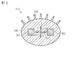
- FIG. 7 The general view which shows the hairbrush of 4th Embodiment. Explanatory drawing which shows the use condition of the hairbrush of 4th Embodiment.
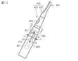
- FIG. 11 is a cross-sectional view taken along line CC in FIG. 10; The general view which shows the eyelash curler of 5th Embodiment. Explanatory drawing which shows the use condition of the eyelash curler of 5th Embodiment.
- FIG. 14 is a cross-sectional view taken along line DD in FIG. 13;
- the shaver 10 includes a handle 20 and a head 30.
- the handle 20 has a housing 40 that can be gripped by the user's fingers.
- the housing 40 has a cylindrical shape as a whole.
- first reference axis X An axis passing through the center of gravity G of the housing 40 and extending in the direction in which the housing 40 extends is defined as a first reference axis X.
- One of the axes orthogonal to the first reference axis X is defined as a second reference axis Y.
- an axis orthogonal to both the first reference axis X and the second reference axis Y is defined as a third reference axis Z.
- One of the directions along the first reference axis X is defined as a first positive direction X1
- the direction opposite to the first positive direction X1 among the directions along the first reference axis X is defined as a first negative direction X2.
- One of the directions along the second reference axis Y is defined as a second positive direction Y1, and the direction opposite to the second positive direction Y1 among the directions along the second reference axis Y is defined as a second negative direction Y2.
- one of the directions along the third reference axis Z is defined as a third positive direction Z1, and the direction opposite to the third positive direction Z1 among the directions along the third reference axis Z is defined as a third negative direction Z2.
- the dimension of the housing 40 in the direction along the first reference axis X is larger than the dimension of the housing 40 in the direction along the second reference axis Y. Further, the dimension of the housing 40 in the direction along the first reference axis X is larger than the dimension of the housing 40 in the direction along the third reference axis Z. As shown in FIG. That is, the housing 40 has a shape elongated in the direction along the first reference axis X. As shown in FIG. The housing 40 is provided with a switch 41 for turning on/off the power of the shaver 10 .
- the housing 40 is roughly divided into a grip portion 40A, a first end portion 40B, and a second end portion 40C.
- the grip portion 40A is the central portion of the housing 40 including the center of gravity G. As shown in FIG. More specifically, the grip portion 40A is a portion that can be positioned inside the user's fingers when the housing 40 is gripped by the fingers.
- the grasping portion 40A is a range of 5 cm in the first positive direction X1 and 5 cm in the first negative direction X2 with the center of gravity G as the center, and a total of 10 cm.
- the first end portion 40B is adjacent to the end of the grip portion 40A on the first positive direction X1 side.
- the second end portion 40C is adjacent to the end of the grip portion 40A on the first negative direction X2 side.
- the head 30 is connected to the end of the housing 40 on the first positive direction X1 side, that is, the first end 40B.
- the head 30 has a rectangular shape elongated in the direction along the second reference axis Y as a whole.
- the head 30 is slightly inclined toward the third positive direction Z1 as it moves toward the first positive direction X1.
- Head 30 has a plurality of blades 31 .
- the blade 31 of the head 30 cuts hair such as beard protruding from the skin as the head 30 moves on the skin.
- the handle 20 includes a first vibrating body 51 and a second vibrating body 52.
- the first vibrating body 51 is built in the first end portion 40B of the housing 40 .
- the first vibrating body 51 has a substantially cubic shape.
- Each surface of the outer surface of the first vibrating body 51 extends in a first positive direction X1, a first negative direction X2, a second positive direction Y1, a second negative direction Y2, a third positive direction Z1, and a third negative direction Z2, respectively. I'm on my way.
- the first vibrating body 51 includes a voice coil motor corresponding to each surface, a weight corresponding to each voice coil motor, and a cubic case that accommodates them.
- the weight vibrates due to the force generated by the current flowing through the coil of the voice coil motor.
- the case vibrates due to the vibration of the weight. Therefore, the first vibrating body 51 can move along the first reference axis X, the second reference axis Y, and the third reference axis Z by controlling the current flowing through the coils of the voice coil motor. vibrate to each of the More specifically, for example, it is a vibrating body as described in Japanese Unexamined Patent Application Publication No. 2005-190465.
- the first vibrating body 51 is positioned on the first reference axis X. As shown in FIG. Also, the first vibrating body 51 is positioned on the first positive direction X1 side when viewed from the center of gravity G of the housing 40 .
- the second vibrating body 52 is built in the second end portion 40C of the housing 40 .
- the second vibrating body 52 is a vibrating body similar to the first vibrating body 51 .
- the second vibrating body 52 is positioned on the first reference axis X. As shown in FIG.
- the second vibrating body 52 is located on the first negative direction X2 side when viewed from the center of gravity G of the housing 40 .
- the distance from the center of gravity G of the housing 40 to the first vibrating body 51 is equal to the distance from the center of gravity G of the housing 40 to the second vibrating body 52 .
- the shaver 10 has a tilt sensor 61 and a pressure sensor 62 .
- the tilt sensor 61 is a triaxial acceleration sensor. That is, the tilt sensor 61 detects the attitude of the steering wheel 20 with reference to the direction of gravity. Specifically, the tilt sensor 61 stores in advance the orientation of the first negative direction X2 viewed from the tilt sensor 61 .
- the first negative direction X2 is a fixed direction determined by the shape of the housing 40, and the first negative direction X2 viewed from the tilt sensor 61 is also always a fixed direction.
- the tilt sensor 61 identifies the direction of gravity based on the detected acceleration.
- the tilt sensor 61 detects the angle between the straight line extending from the tilt sensor 61 in the gravitational direction and the straight line extending from the tilt sensor 61 in the first negative direction X2. Identified as a tilt angle. Therefore, the tilt sensor 61 sets the tilt angle to 0 degrees when the direction of gravity matches the first negative direction X2. The tilt sensor 61 sets the tilt angle to 180 degrees when the direction of gravity coincides with the first positive direction X1.
- the pressure sensor 62 is positioned near the blade 31 in the head 30 .
- the pressure sensor 62 detects pressure in the direction from the blade 31 toward the first negative direction X2. That is, the pressure sensor 62 detects that the blade 31 is pressed against the user's skin.
- the shaver 10 has a control device 70 .
- the control device 70 includes a CPU and a ROM, and executes software processing.
- the control device 70 acquires a signal indicating the tilt angle of the first reference axis X from the tilt sensor 61 .
- Controller 70 obtains a signal indicative of pressure from pressure sensor 62 .
- the control device 70 particularly controls the actuation of the first vibrating body 51 and the actuation of the second vibrating body 52 .
- the control device 70 can generate a force sensation in the first vibrating body 51 by controlling the vibration pattern of the first vibrating body 51 .
- the directions of the force sense generated by the first vibrating body 51 are the first positive direction X1, the first negative direction X2, the second positive direction Y1, the second negative direction Y2, the third positive direction Z1, and the third positive direction Z1. Any one of the three negative directions Z2 can be selected.
- the control device 70 controls currents to flow in the respective voice coil motors of the first vibrating body 51 to control the direction along the first reference axis X, the direction along the second reference axis Y, and the direction along the third reference axis. Vibration is generated with an amplitude direction in one of the directions along the Z-axis.
- control device 70 controls the vibration pattern of the vibration in the direction along such one reference axis, thereby generating a force sense in one direction or the other direction of the reference axis.
- the sense of force is a sense of resistance received from an object. Therefore, for example, when the first vibrating body 51 is caused to generate a force sensation in the first positive direction X1, the user feels that the first vibrating body 51 is actually reciprocating at the same position. 1 It feels as if the vibrating body 51 is displaced in the first positive direction X1.
- the force sense generated by the first vibrating body 51 will be referred to as the first force sense
- the direction of the first force sense will be referred to as the first direction.
- the control device 70 can generate a force sensation in the second vibrating body 52 by controlling the vibration pattern of the second vibrating body 52 in the same manner as the first vibrating body 51 .
- the force sense generated by the second vibrating body 52 is referred to as the second force sense
- the direction of the second force sense is referred to as the second direction.
- the control device 70 can execute the first control that determines the first direction of the first force sense and the second direction of the second force sense to specific directions.
- the first direction and the second direction are opposite directions.
- the imaginary line extending from the first vibrating body 51 in the first direction and the imaginary line extending from the second vibrating body 52 in the second direction are not positioned on the same straight line.
- the control device 70 can execute two different types of control as the first control.
- One of the two types of first control is rotation promotion control, and the other is rotation suppression control.
- the control device 70 executes rotation promotion control or rotation suppression control according to the attitude of the steering wheel 20 acquired from the tilt sensor 61 and the pressure acquired by the pressure sensor 62 .
- the control device 70 executes rotation promotion control under the condition that the attitude of the steering wheel 20 is within a predetermined range.
- the posture within the predetermined range is a posture in which the handle 20 is generally along the axis along the direction of gravity. Specifically, the posture within a predetermined range means that the tilt angle of the first reference axis X is 10 degrees or less.
- control device 70 executes the rotation promotion control under one of the conditions that the pressure acquired by the pressure sensor 62 continues to be higher than the prescribed pressure for a certain period of time or longer.
- the specified pressure is defined as a pressure that can detect that the head 30 is in contact with the skin.
- the certain period of time is a period of time sufficient to determine that the user is shaving, and is set to several seconds, for example.
- the control device 70 executes rotation acceleration control when the above two conditions are satisfied.
- the first direction which is the direction of the first force sense of the first vibrating body 51
- the second direction which is the direction of the second force sense of the second vibrating body 52
- the control device 70 executes rotation suppression control with one of the conditions being that the tilt sensor 61 detects a change in the attitude of the steering wheel 20 .
- the change amount per unit time in which the first vibrating body 51 moves in the third positive direction Z1 or the third negative direction Z2 is defined as a first movement change amount.
- the amount of change per unit time in which the second vibrating body 52 moves in the direction opposite to the moving direction of the first vibrating body 51 is defined as a second movement change amount.
- a change in the attitude of the handle 20 means that the difference per unit time between the first amount of movement change and the second amount of movement change becomes greater than a predetermined threshold value.
- the difference per unit time between the first movement change amount and the second movement change amount is calculated by subtraction or division.
- the threshold value is the amount by which one of the first end portion 40B or the second end portion 40C of the handle 20 rotates abruptly with respect to the other when the handle 20 is viewed from the second reference axis Y. It is defined as a value that indicates
- the control device 70 detects that the attitude of the steering wheel 20 has changed when the following conditions are satisfied. First, the change in the tilt angle of the first reference axis X acquired by the tilt sensor 61 exceeds the permissible amount of change per unit time. The permissible amount of change per unit time is, for example, 15 degrees per 0.1 second. In addition, the control device 70 executes the rotation suppression control under one of the conditions that the pressure acquired by the pressure sensor 62 becomes less than the specified pressure from a state of the specified pressure or higher. In this way, when the handle 20 is viewed from the second reference axis Y, for example, the second end 40C rotates around the head 30 and the head 30 leaves the skin. Then, rotation suppression control is executed.
- the control device 70 executes rotation suppression control when the above two conditions are satisfied.
- the control device 70 rotates the first vibrating body 51 in the first direction and the second vibrating body 52 so as to generate the force sensation of rotating the steering wheel 20 in the direction opposite to the rotating direction. set the second direction of
- the control device 70 sets the first direction of the first vibrating body 51 as the third positive direction Z1 and sets the second direction of the second vibrating body 52 as the third negative direction Z2 in the rotation suppression control.
- the first movement change amount is the change amount per unit time of movement of the first vibrating body 51 in the second direction
- the second movement change amount is the unit of movement of the second vibrating body 52 in the first direction. It is the amount of change per hour.
- the control device 70 sets the first direction of the first vibrating body 51 as the third negative direction Z2 and sets the second direction of the second vibrating body 52 as the third positive direction Z1 in the rotation suppression control.
- the first vibrating body 51 rotates in the second positive direction Y1 or the second negative direction Y2
- the first vibrating body 51 is set so as to generate a force sensation of rotating in the direction opposite to the rotation.
- a first direction of the body 51 and a second direction of the second vibrating body 52 are set.
- the user wants to shave the beard under the chin.
- the user holds the shaver 10 so that the third positive direction Z1 of the shaver 10 faces his/her rear.
- the user puts the head 30 under the chin in a posture in which the first reference axis X of the handle 20 is generally aligned with the axis along the direction of gravity. That is, the state where the tilt angle of the steering wheel 20 is in the range of 10 degrees or less and the pressure acquired by the pressure sensor 62 is higher than the specified pressure continues for a certain period of time or longer. Therefore, the conditions for executing the rotation promotion control of the first control are satisfied.
- the first direction of the first vibrating body 51 is the third negative direction Z2, and the second direction of the second vibrating body 52 is the third positive direction Z1. Therefore, when the user is shaving under the chin, the handle 20 gives a sense of force as if the head 30 is moving in the direction of gravity while following the skin from under the chin toward the mouth.
- the user shaves the cheeks.
- the posture of the shaver 10 may suddenly change due to a twist of the wrist or the like.
- the change in posture of the handle 20 may be a change in rotation about the second reference axis Y, and the head 30 may be separated from the skin.
- the change in posture of the handle 20 is a change in which the second end portion 40C rotates about the head 30 as the rotation axis when the shaver 10 is viewed from the direction along the second reference axis Y. Yes, and the head 30 may separate from the skin. In these cases, the conditions for executing the rotation suppression control of the first control are satisfied.
- the first vibrating body 51 is rotated in the first direction and the second vibrating body 52 is rotated in the second direction so as to generate a force sensation that the steering wheel 20 rotates in a direction opposite to the actual rotation.
- the first direction and the second direction are opposite directions. Further, in the first control, the first vibrating body 51 is moved so that the virtual line extending from the first vibrating body 51 in the first direction and the virtual line extending from the second vibrating body 52 in the second direction are not on the same straight line. and the vibration pattern of the second vibrating body 52 are controlled. Therefore, it is possible to give the user holding the housing 40 of the handle 20 a sense of force as if the handle 20 were rotating. Therefore, the user can be guided to the situation in which the handle 20 should be rotated.
- the first vibrating body 51 is positioned on the first positive direction X1 side when viewed from the center of gravity G of the housing 40 . Further, the second vibrating body 52 is positioned on the first negative direction X2 side when viewed from the center of gravity G of the housing 40 . Therefore, it is possible to guide the user that the long housing 40 should be rotated in a direction in which it is toppled over.
- the distance from the center of gravity G of the housing 40 to the first vibrating body 51 and the distance from the center of gravity G of the housing 40 to the second vibrating body 52 are equal. It's becoming Therefore, by setting the magnitude of the first force sense presented by the first vibrating body 51 and the magnitude of the second force sense presented by the second vibrating body 52 to be the same, the housing 40 can move around the center of gravity G of the housing 40 . It is possible to generate a haptic sensation that the body 40 rotates. Therefore, it is not necessary to employ different specifications for the first vibrating body 51 and the second vibrating body 52, or to control them with different amplitude patterns.
- the housing 40 has a grip portion 40A, a first end portion 40B, and a second end portion 40C.
- the first vibrating body 51 is built in the first end portion 40B.
- the second vibrating body 52 is built in the second end portion 40C. Therefore, the first vibrating body 51 and the second vibrating body 52 are positioned considerably apart. Therefore, when viewed from the center of gravity G of the housing 40, the first force sense and the second force sense are generated from a distant location. As a result, it becomes possible to efficiently give a force sensation to the user, so that even if the magnitudes of the first force sensation and the second force sensation are not so large, the force sensation of rotation can be generated in the user. can.
- the shaver 10 is moved while changing the posture of the handle 20 . Also, when shaving the beard around the chin, there is a high possibility that the posture of the handle 20 is within a certain range. According to the first embodiment described above, when the posture of the steering wheel 20 is within a predetermined range, it is possible to give the force sensation of rotating the steering wheel 20 by the rotation promotion control. Therefore, it is possible to guide the user to change the posture of the handle 20 and thus the shaver 10 .
- the shaver 10 for example, when shaving the cheeks, it is preferable to move the shaver 10 so as not to change the posture of the handle 20 abruptly. According to the first embodiment, when the posture of the handle 20 suddenly changes, it is possible to guide the situation where the posture of the shaver 10 should be returned by the rotation suppression control.
- the hair dryer 110 has a handle 120 and a head 130 .
- the handle 120 has a housing 140 that can be grasped by the user's fingers.
- the housing 140 has a cylindrical shape as a whole.
- first reference axis X An axis passing through the center of gravity G of the housing 140 and extending in the direction in which the housing 140 extends is defined as a first reference axis X.
- One of the axes orthogonal to the first reference axis X is defined as a second reference axis Y.
- an axis orthogonal to both the first reference axis X and the second reference axis Y is defined as a third reference axis Z.
- One of the directions along the first reference axis X is defined as a first positive direction X1
- the direction opposite to the first positive direction X1 among the directions along the first reference axis X is defined as a first negative direction X2.
- One of the directions along the second reference axis Y is defined as a second positive direction Y1, and the direction opposite to the second positive direction Y1 among the directions along the second reference axis Y is defined as a second negative direction Y2.
- one of the directions along the third reference axis Z is defined as a third positive direction Z1, and the direction opposite to the third positive direction Z1 among the directions along the third reference axis Z is defined as a third negative direction Z2.
- the dimension of the housing 140 in the direction along the first reference axis X is larger than the dimension of the housing 140 in the direction along the second reference axis Y. Further, the dimension of the housing 140 in the direction along the first reference axis X is larger than the dimension of the housing 140 in the direction along the third reference axis Z. As shown in FIG. That is, the housing 140 has a shape elongated in the direction along the first reference axis X. As shown in FIG. The housing 140 is provided with a switch 141 for turning on/off the power of the hair dryer 110 .
- the head 130 is connected to the end of the housing 140 on the first positive direction X1 side.
- the head 130 has a cylindrical shape elongated in the direction along the second reference axis Y as a whole.
- the head 130 has an air blower 131 capable of blowing warm air.
- the air blower 131 has a heating element for heating air and a fan for blowing air. The heated air is blown outward from the tip side of the air blowing portion 131 of the head 130 .
- the air blowing unit 131 may be capable of blowing cold air without being limited to hot air.
- the hair dryer 110 includes a first vibrating body 151, a second vibrating body 152, a third vibrating body 153, a fourth vibrating body 154, a fifth vibrating body 155, and a sixth vibrating body 156. .
- Each vibrating body has the same configuration as the vibrating body of the first embodiment.
- the first vibrating body 151 is built into the housing 140 of the handle 120 .
- the first vibrating body 151 is positioned on the first positive direction X1 side and the second positive direction Y1 side when viewed from the center of gravity G of the housing 140 .
- the second vibrating body 152 is built into the housing 140 of the handle 120 .
- the second vibrating body 152 is positioned on the first positive direction X1 side and the second negative direction Y2 side when viewed from the center of gravity G of the housing 140 .
- the distance from the center of gravity G of the housing 140 to the first vibrating body 151 is equal to the distance from the center of gravity G of the housing 140 to the second vibrating body 152 .
- the third vibrating body 153 is built in the housing 140 of the handle 120.
- the third vibrating body 153 is positioned on the first negative direction X2 side and the second positive direction Y1 side when viewed from the center of gravity G of the housing 140 .
- the distance from the center of gravity G of the housing 140 to the third vibrating body 153 and the distance from the center of gravity G of the housing 140 to the first vibrating body 151 are equal.
- the fourth vibrating body 154 is built in the housing 140 of the handle 120.
- the fourth vibrating body 154 is positioned on the first negative direction X2 side and the second negative direction Y2 side when viewed from the center of gravity G of the housing 140 .
- the distance from the center of gravity G of the housing 140 to the second vibrating body 152 and the distance from the center of gravity G of the housing 140 to the fourth vibrating body 154 are equal.
- the fifth vibrating body 155 is built into the head 130 .
- the fifth vibrating body 155 is positioned on the first positive direction X1 side and the second positive direction Y1 side when viewed from the center of gravity G of the housing 140 .
- the sixth vibrating body 156 is built in the head 130 .
- the sixth vibrating body 156 is positioned on the first negative direction X2 side and the second negative direction Y2 side when viewed from the center of gravity G of the housing 140 .
- the distance from the center of gravity G of the housing 140 to the fifth vibrating body 155 and the distance from the center of gravity G of the housing 140 to the sixth vibrating body 156 are equal.
- the first vibrating body 151, the third vibrating body 153, and the fifth vibrating body 155 are present at the same position when the hair dryer 110 is viewed in the direction along the first reference axis X.
- the second vibrating body 152, the fourth vibrating body 154, and the sixth vibrating body 156 are present at the same position when the hair dryer 110 is viewed in the direction along the first reference axis X. Further, when the hair dryer 110 is viewed in the direction along the first reference axis X, the positions of the first vibrating body 151 and the second vibrating body 152 are in a symmetrical relationship with the first reference axis X interposed therebetween. .
- the hair dryer 110 is equipped with a tilt sensor 161.
- the tilt sensor 161 has the same configuration as the tilt sensor 61 in the first embodiment. That is, the tilt sensor 161 detects the tilt angle of the first reference axis X with respect to the direction of gravity.
- the hair dryer 110 has a controller 170 .
- the control device 170 has a CPU and a ROM and executes software processing.
- the control device 170 acquires a signal indicating the tilt from the tilt sensor 161 .
- the control device 170 controls the operation of each vibrator.
- the control device 170 can generate a first force sense from the first vibrating body 151 in the first direction.
- the control device 170 can generate a second force sense in the second direction from the second vibrating body 152 by controlling the vibration pattern of the second vibrating body 152 .
- the control device 170 can generate a third force sense in the third direction from the third vibrating body 153 by controlling the vibration pattern of the third vibrating body 153 .
- the control device 170 can generate a fourth force sense in the fourth direction from the fourth vibrating body 154 by controlling the vibration pattern of the fourth vibrating body 154 .
- the control device 170 can generate a fifth force sense in the fifth direction from the fifth vibrating body 155 by controlling the vibration pattern of the fifth vibrating body 155 .
- the control device 170 can generate a sixth force sense in the sixth direction from the sixth vibrating body 156 by controlling the vibration pattern of the sixth vibrating body 156 .
- the control device 170 can execute first control and second control for controlling the control pattern of each vibrator.
- first direction and the second direction are opposite directions.
- the virtual line extending from the first vibrating body 151 in the first direction and the imaginary line extending from the second vibrating body 152 in the second direction are not positioned on the same straight line.
- the relationship between the third direction and the fourth direction is similar to that of the first direction and the second direction.
- the relationship between the fifth direction and the sixth direction is the same as that between the first direction and the second direction.
- the control device 170 executes the first control
- the first direction of the first force sense, the third direction of the third force sense, and the fifth direction of the fifth force sense are all changed to the first direction.
- the positive direction Z1 the positive direction
- the control device 170 executes the first control
- the second direction of the second force sense, the fourth direction of the fourth force sense, and the sixth direction of the sixth force sense are all changed to the third negative direction. Let it be Z2.
- the control device 170 makes the first to sixth directions all opposite to the directions in the first control.
- the first direction of the first force sense, the third direction of the third force sense, and the fifth direction of the fifth force sense are defined as a third negative direction Z2.
- the control device 170 sets the second direction of the second force sense, the fourth direction of the fourth force sense, and the sixth direction of the sixth force sense as the third positive direction Z1. That is, the second control reverses the first direction and the second direction.
- the virtual line extending from the first vibrating body 151 in the first direction and the imaginary line extending from the second vibrating body 152 in the second direction do not lie on the same straight line. .
- control device 170 alternately and repeatedly executes the first control and the second control as alternate rotation promotion control every predetermined period.
- the predetermined period is, for example, less than 1 second.
- the control device 170 executes alternate rotation promotion control on condition that the posture of the handle 120 is within a predetermined range. Specifically, the control device 170 executes alternate rotation promotion control on the condition that the tilt angle of the first reference axis X acquired by the tilt sensor 161 is equal to or greater than a predetermined tilt angle.
- the specified tilt angle is, for example, 45 degrees, and is a tilt that can be said to be a posture in which the handle 120 is considerably tilted with respect to the axis along the direction of gravity.
- the first control provides the user with a force sensation of rotating clockwise about the first reference axis X. fingers.
- the second control gives the fingers of the user a force sensation as if the hair dryer rotates counterclockwise about the first reference axis X as the rotation axis.
- the control device 170 gives the finger of the user a force sensation of rotating clockwise about the first reference axis X as a rotation axis, A counterclockwise rotating force sensation is alternately given.
- the control device 170 executes the alternate rotation promotion control, the user feels a sense of force as if the head 130 of the hair dryer 110 were repeatedly shaken.
- the housing 140 is elongated in the direction along the first reference axis X.
- the first vibrating body 151 is positioned on the second positive direction Y1 side when viewed from the center of gravity G of the housing 140 .
- the second vibrating body 152 is positioned on the second negative direction Y2 side when viewed from the center of gravity G of the housing 140 . Therefore, according to the alternate rotation acceleration control, it is possible to guide the user that the long housing 140 should be alternately rotated in a twisting direction.
- FIG. 1 A third embodiment in which the handle is applied to a hair iron will be described below with reference to the drawings. It should be noted that the drawings may show constituent elements in an enlarged manner in order to facilitate understanding. The dimensional ratios of components may differ from those in reality or in other drawings.
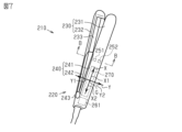
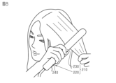
- the hair iron 210 includes a handle 220 and a head 230.
- the handle 220 has a housing 240 that can be grasped by the user's fingers.
- the housing 240 has a first housing 241 and a second housing 242 .
- the first housing 241 has a columnar shape as a whole.
- the second housing 242 has a columnar shape as a whole.
- first reference axis X An axis passing through the center of gravity G of the first housing 241 and extending in the direction in which the first housing 241 extends is defined as a first reference axis X.
- One of the axes orthogonal to the first reference axis X is defined as a second reference axis Y.
- an axis orthogonal to both the first reference axis X and the second reference axis Y is defined as a third reference axis Z.
- One of the directions along the first reference axis X is defined as a first positive direction X1
- the direction opposite to the first positive direction X1 among the directions along the first reference axis X is defined as a first negative direction X2.
- One of the directions along the second reference axis Y is defined as a second positive direction Y1, and the direction opposite to the second positive direction Y1 among the directions along the second reference axis Y is defined as a second negative direction Y2.
- one of the directions along the third reference axis Z is defined as a third positive direction Z1, and the direction opposite to the third positive direction Z1 among the directions along the third reference axis Z is defined as a third negative direction Z2.
- the dimension of the first housing 241 in the direction along the first reference axis X is larger than the dimension of the first housing 241 in the direction along the second reference axis Y. Also, the dimension of the first housing 241 in the direction along the first reference axis X is larger than the dimension of the first housing 241 in the direction along the third reference axis Z. As shown in FIG. That is, the first housing 241 has a shape elongated in the direction along the first reference axis X. As shown in FIG. Similarly, the second housing 242 also has an elongated shape in the direction along the first reference axis X. As shown in FIG.
- the second housing 242 is adjacent to and substantially parallel to the first housing 241 on the third negative direction Z2 side when viewed from the first housing 241 .
- the end of the first housing 241 in the first negative direction X2 is connected to the end of the second housing 242 in the first negative direction X2 via the shaft 243 .
- the first housing 241 is rotatable relative to the second housing 242 with the shaft 243 as a rotation axis. That is, the first housing 241 and the second housing 242 can be opened and closed with the shaft 243 as a fulcrum.
- the head 230 has a first pinching portion 231 and a second pinching portion 232 .
- the first pinching portion 231 is connected to the end of the first housing 241 on the first positive direction X1 side.
- the first sandwiching portion 231 has a rectangular shape elongated in the direction along the first reference axis X as a whole.
- the second pinching portion 232 has the same shape as the first pinching portion 231 .
- the second clamping portion 232 has a heater 233 .
- the second pinching portion 232 is connected to the second housing 242 so as to face the first pinching portion 231 . Then, when the first housing 241 and the second housing 242 are closed, the hair can be caught between the first pinching portion 231 and the second pinching portion 232 . Then, with the hair sandwiched between the first sandwiching portion 231 and the second sandwiching portion 232, the heater 233 in the second sandwiching portion 232 can adjust the overall shape of the hair.
- the handle 220 has a first vibrating body 251 and a second vibrating body 252 .
- Each vibrating body has the same configuration as the vibrating body in the first embodiment.
- the first vibrating body 251 is built in the first housing 241 .
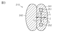
- the first vibrating body 251 is positioned on the first positive direction X1 side and the second positive direction Y1 side when viewed from the center of gravity G of the first housing 241 .
- the second vibrating body 252 is built in the first housing 241 .
- the second vibrating body 252 is positioned on the first positive direction X1 side and the second negative direction Y2 side when viewed from the center of gravity G of the first housing 241 .
- the distance from the center of gravity G of the first housing 241 to the first vibrating body 251 is equal to the distance from the center of gravity G of the first housing 241 to the second vibrating body 252 .
- the hair iron 210 is provided with an inclination sensor 261.
- the tilt sensor 261 has the same configuration as the tilt sensor 61 in the first embodiment.
- the tilt sensor 261 detects rotation of the first housing 241 around the first reference axis X as a change in posture of the first housing 241 .
- the tilt sensor 261 detects that the first housing 241 rotates about the first reference axis X when both the second positive direction Y1 and the third positive direction Z1 change.
- the hair iron 210 includes a control device 270.
- the control device 270 has a CPU and a ROM and executes software processing.
- the control device 270 acquires a signal indicating whether or not the first housing 241 has rotated.
- the control device 270 controls the operation of each vibrator.
- the control device 270 can generate a first force sense from the first vibrating body 251 in the first direction.
- the control device 270 can generate a second force sense in the second direction from the second vibrating body 252 by controlling the vibration pattern of the second vibrating body 252 .
- the control device 270 can perform first control for controlling the vibration pattern of the first vibrating body 251 and the vibration pattern of the second vibrating body 252 .
- first direction and the second direction are opposite directions.
- the virtual line extending from the first vibrating body 251 in the first direction and the imaginary line extending from the second vibrating body 252 in the second direction are not positioned on the same straight line.
- control device 270 executes the first control as rotation suppression control.
- Control device 270 executes rotation suppression control on the condition that tilt sensor 261 detects a change in the posture of steering wheel 220 .
- the control device 270 detects that both the amount of change per unit time in the second positive direction Y1 and the amount of change per unit time in the third positive direction Z1 detected by the tilt sensor 261 exceed the allowable amount of change.
- the permissible amount of change per unit time is, for example, 15 degrees per 0.1 second.
- the rotation suppression control is performed when the change in attitude of the handle 220 is a change in which the handle 220 rotates about the first reference axis X as the rotation axis.
- the first vibrator 251 rotates in the first direction and in the second direction so as to generate a force sensation that the handle 220 rotates in the direction opposite to the rotation about the first reference axis X as the rotation axis.
- a second direction of the vibrating body 252 is set. In other words, assume that the handle 220 rotates such that the first vibrating body 251 moves in the third negative direction Z2 and the second vibrating body 252 moves in the third positive direction Z1.
- the control device 270 performs the first control with the first direction of the first vibrating body 251 as the third positive direction Z1 and the second direction of the second vibrating body 252 as the third negative direction Z2.
- the user preferably moves the handle 220 in parallel in the second positive direction Y1 or the second negative direction Y2 while keeping the tilt angle of the first reference axis X constant.
- the handle 220 may rotate about the first reference axis X as the rotation axis. According to the third embodiment, when such rotation of the steering wheel 220 occurs, the conditions for executing the first control as the rotation suppression control are satisfied.
- FIG. 9 illustrates a state in which the first housing 241 and the second housing 242 are closed.
- the rotation suppression control can guide the situation where the attitude of the hair iron 210 should be returned.
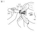
- hairbrush 310 includes handle 320 and head 330 .
- the handle 320 has a housing 340 that can be grasped by the user's fingers.
- the housing 340 has a cylindrical shape as a whole.
- first reference axis X An axis passing through the center of gravity G of the housing 340 and extending in the direction in which the housing 340 extends is defined as a first reference axis X.
- One of the axes orthogonal to the first reference axis X is defined as a second reference axis Y.
- an axis orthogonal to both the first reference axis X and the second reference axis Y is defined as a third reference axis Z.
- One of the directions along the first reference axis X is defined as a first positive direction X1
- the direction opposite to the first positive direction X1 among the directions along the first reference axis X is defined as a first negative direction X2.
- One of the directions along the second reference axis Y is defined as a second positive direction Y1, and the direction opposite to the second positive direction Y1 among the directions along the second reference axis Y is defined as a second negative direction Y2.
- one of the directions along the third reference axis Z is defined as a third positive direction Z1, and the direction opposite to the third positive direction Z1 among the directions along the third reference axis Z is defined as a third negative direction Z2.
- the dimension of the housing 340 in the direction along the first reference axis X is larger than the dimension of the housing 340 in the direction along the second reference axis Y. Further, the dimension of the housing 340 in the direction along the first reference axis X is larger than the dimension of the housing 340 in the direction along the third reference axis Z. That is, the housing 340 has a shape elongated in the direction along the first reference axis X. As shown in FIG. The housing 340 is provided with a switch 341 for turning on/off the power of the hairbrush 310 .
- the head 330 is connected to the end of the housing 340 on the first positive direction X1 side.
- the head 330 has a cylindrical shape elongated in the direction along the first reference axis X as a whole.
- the head 330 has a brush 331 for brushing hair. The hair is brushed by moving the hairbrush 310 while putting the brush 331 on the hair.
- the head 330 has a heating element for heating the air and a fan for blowing the air. The heated air is blown outside through between the protrusions of the brush 331 .
- the hairbrush 310 includes a first vibrating body 351 , a second vibrating body 352 , a third vibrating body 353 and a fourth vibrating body 354 .
- Each vibrating body has the same configuration as the vibrating body of the first embodiment.
- the first vibrating body 351 is built in the housing 340 of the handle 320 .
- the first vibrating body 351 is positioned on the first positive direction X1 side and the second positive direction Y1 side when viewed from the center of gravity G of the housing 340 .
- the second vibrating body 352 is built into the housing 340 of the handle 320 .
- the second vibrating body 352 is positioned on the first positive direction X1 side and the second negative direction Y2 side when viewed from the center of gravity G of the housing 340 .
- the distance from the center of gravity G of the housing 340 to the first vibrating body 351 and the distance from the center of gravity G of the housing 340 to the second vibrating body 352 are equal.
- the third vibrating body 353 is built in the housing 340 of the handle 320.
- the third vibrating body 353 is positioned on the first negative direction X2 side and the second positive direction Y1 side when viewed from the center of gravity G of the housing 340 .
- the distance from the center of gravity G of the housing 340 to the third vibrating body 353 and the distance from the center of gravity G of the housing 340 to the first vibrating body 351 are equal.
- the fourth vibrating body 354 is built into the housing 340 of the handle 320.
- the fourth vibrating body 354 is positioned on the first negative direction X2 side and the second negative direction Y2 side when viewed from the center of gravity G of the housing 340 .
- the distance from the center of gravity G of the housing 340 to the second vibrating body 352 and the distance from the center of gravity G of the housing 340 to the fourth vibrating body 354 are equal.
- the first vibrating body 351 and the third vibrating body 353 are present at the same position when the hairbrush 310 is viewed in the direction along the first reference axis X.
- the second vibrating body 352 and the fourth vibrating body 354 are present at the same position when the hairbrush 310 is viewed in the direction along the first reference axis X.
- the position of the first vibrating body 351 and the position of the second vibrating body 352 are in a symmetrical relationship with the first reference axis X interposed therebetween. .
- the hairbrush 310 includes a control device 370.
- the control device 370 has a CPU and a ROM and executes software processing.
- the controller 370 controls the operation of each vibrator.
- the control device 370 can generate a first force sense from the first vibrating body 351 in the first direction.
- the control device 370 can generate a second force sense in the second direction from the second vibrating body 352 by controlling the vibration pattern of the second vibrating body 352 .
- the control device 370 can generate a third force sense in the third direction from the third vibrating body 353 by controlling the vibration pattern of the third vibrating body 353 .
- the control device 370 can generate a fourth force sense in the fourth direction from the fourth vibrating body 354 by controlling the vibration pattern of the fourth vibrating body 354 .
- the control device 370 can execute first control and second control for controlling the control pattern of each vibrator.
- first direction and the second direction are opposite directions.
- the virtual line extending from the first vibrating body 351 in the first direction and the imaginary line extending from the second vibrating body 352 in the second direction are not positioned on the same straight line.
- the relationship between the third direction and the fourth direction is similar to that of the first direction and the second direction.
- the first direction of the first force sense and the third direction of the third force sense are both the third positive direction Z1. Further, when the control device 370 executes the first control, both the second direction of the second force sense and the fourth direction of the fourth force sense are set as the third negative direction Z2.
- the control device 370 causes the first to fourth directions to be opposite to the directions in the first control.
- the first direction of the first force sense and the third direction of the third force sense are defined as a third negative direction Z2.
- the control device 370 sets the second direction of the second force sense and the fourth direction of the fourth force sense as the third positive direction Z1. That is, the second control reverses the first direction and the second direction.
- the virtual line extending from the first vibrating body 351 in the first direction and the imaginary line extending from the second vibrating body 352 in the second direction are not positioned on the same straight line. . In this regard, the same applies to the orientation relationship between the third direction and the fourth direction.
- the control device 370 executes the first control and the second control in a predetermined order as the specific rotation promotion control for each predetermined time.
- the order of each control is defined as the order in which the first control and the second control are alternately performed.
- the time for performing each control is set to 3 seconds for the first control and 1 second for the second control.
- the control device 370 executes the first control and the second control in a predetermined order as the specific rotation promotion control for each predetermined time.
- the first control causes the user's fingers to feel as if the hairbrush is rotating clockwise about the first reference axis X.
- the second control gives the finger of the user a force sensation as if the hairbrush 310 rotates counterclockwise about the first reference axis X as the rotation axis.
- the finger gripping the housing 340 of the handle 320 feels as if it is rotating by a specified amount every specified time. can give Therefore, the user is guided to rotate the handle 320 according to the reproducible feeling of rotation. As a result, the user can achieve similar brushing with high reproducibility.
- the first control and the second control are executed in a predetermined order for each predetermined time. Therefore, it is possible to guide the second control to return the rotation by the amount operated to rotate by the first control.
- eyelash curler 410 includes handle 420 and head 430 .
- the handle 420 has a housing 440 that can be grasped by the user's fingers.
- the housing 440 has a cylindrical shape as a whole.
- An axis passing through the center of gravity G of the housing 440 and extending in the direction in which the housing 440 extends is defined as a first reference axis X.
- One of the axes orthogonal to the first reference axis X is defined as a second reference axis Y.
- an axis orthogonal to both the first reference axis X and the second reference axis Y is defined as a third reference axis Z.
- One of the directions along the first reference axis X is defined as a first positive direction X1
- the direction opposite to the first positive direction X1 among the directions along the first reference axis X is defined as a first negative direction X2.
- One of the directions along the second reference axis Y is defined as a second positive direction Y1, and the direction opposite to the second positive direction Y1 among the directions along the second reference axis Y is defined as a second negative direction Y2.
- one of the directions along the third reference axis Z is defined as a third positive direction Z1, and the direction opposite to the third positive direction Z1 among the directions along the third reference axis Z is defined as a third negative direction Z2.
- the dimension of the housing 440 in the direction along the first reference axis X is larger than the dimension of the housing 440 in the direction along the second reference axis Y. Further, the dimension of the housing 440 in the direction along the first reference axis X is larger than the dimension of the housing 440 in the direction along the third reference axis Z. That is, the housing 440 has a shape elongated in the direction along the first reference axis X. As shown in FIG. The housing 440 is provided with a switch 441 for turning on/off the power of the eyelash curler 410 .
- the head 430 is connected to the end of the housing 440 on the first positive direction X1 side.
- the head 430 has a cylindrical shape elongated in the direction along the first reference axis X as a whole.
- the head 430 has a clip 431 for holding eyelashes.
- the clip 431 of the head 430 pinches the eyelashes, and the handle 420 is rotated around the first reference axis X to curl the eyelashes.
- the clip 431 has a heater. By driving the heater, heat is applied to the eyelashes sandwiched by the clip 431 .
- the handle 420 includes a first vibrating body 451 and a second vibrating body 452 .
- Each vibrating body has the same configuration as the vibrating body in the first embodiment.
- the first vibrating body 451 is built in the housing 440 .
- the first vibrating body 451 is located on the first positive direction X1 side and the second positive direction Y1 side when viewed from the center of gravity G of the housing 440.
- the second vibrating body 452 is built in the housing 440. there is The second vibrating body 452 is positioned on the first positive direction X1 side and the second negative direction Y2 side when viewed from the center of gravity G of the housing 440 .
- the distance from the center of gravity G of the housing 440 to the first vibrating body 451 is equal to the distance from the center of gravity G of the housing 440 to the second vibrating body 452 .
- the eyelash curler 410 has a tilt sensor 461 .
- the tilt sensor 461 has the same configuration as the tilt sensor 61 in the first embodiment.
- the tilt sensor 461 detects rotation of the housing 440 about the first reference axis X as a change in posture of the housing 440 . Specifically, the tilt sensor 461 detects that the housing 440 has rotated about the first reference axis X when both the second positive direction Y1 and the third positive direction Z1 change.
- the eyelash curler 410 has a controller 470 .
- the control device 470 has a CPU and a ROM and executes software processing.
- Control device 470 acquires a signal indicating whether housing 440 has rotated from tilt sensor 461 .
- the control device 270 controls the operation of each vibrator.
- the control device 470 can generate a first force sense from the first vibrating body 451 in the first direction.
- the control device 470 can generate a second force sense in the second direction from the second vibrating body 452 by controlling the vibration pattern of the second vibrating body 452 .
- the control device 470 can perform first control for controlling the vibration pattern of the first vibrating body 451 and the vibration pattern of the second vibrating body 452 .
- first direction and the second direction are opposite directions.
- the virtual line extending from the first vibrating body 451 in the first direction and the imaginary line extending from the second vibrating body 452 in the second direction are prevented from being positioned on the same straight line.
- control device 470 executes the first control as rotation promotion control.
- Control device 470 executes rotation suppression control on condition that tilt sensor 461 detects a change in the posture of handle 420 .
- the control device 470 detects that the amount of change per unit time in the second positive direction Y1 detected by the tilt sensor 461 and the amount of change per unit time in the third positive direction Z1 both exceed the allowable amount of change.
- the permissible amount of change per unit time is, for example, 15 degrees per 0.1 second.
- the rotation promotion control is performed.
- the first direction and the second vibration of the first vibrator 451 are generated so as to generate a force sensation that the handle 420 rotates in the same direction as the rotation about the first reference axis X.
- a second orientation of the body 452 is set. In other words, assume that the handle 220 rotates such that the first vibrating body 451 moves in the third negative direction Z2 and the second vibrating body 452 moves in the third positive direction Z1.
- the control device 470 performs the first control with the first direction of the first vibrating body 451 as the third negative direction Z2 and the second direction of the second vibrating body 452 as the third positive direction Z1.
- the first control gives the finger of the user a force sensation as if the first reference axis X is the rotation axis. . Furthermore, the direction of rotation is the same as that generated by twisting the wrist.
- the first control is executed on the condition that the user rotates the eyelash curler 410 and the posture of the handle 420 changes. Moreover, in the first control, a force sense is generated in the same direction as the direction in which the user rotates the eyelash curler 410 . Therefore, it is possible to prevent guiding the rotation in the direction opposite to that intended by the user.
- the shape of the housing may be changed as appropriate.
- the shape of the housing 40 may be cubic or spherical. That is, the dimension of the housing 40 in the direction along the first reference axis X may be the same as the dimension of the housing 40 in the direction along the second reference axis Y, or It may be smaller than the dimension of housing 40 in the direction. In this respect, the relationship between the dimension of the housing 40 in the direction along the first reference axis X and the dimension of the housing 40 in the direction along the third reference axis Z is the same.
- the grip portion 40A of the housing 40 may be the central portion of the housing 40 when the housing 40 is divided into three equal parts in the direction along the first reference axis X.
- the first end portion 40B is a portion including the end on the first positive direction X1 side among the three equally divided portions
- the second end portion 40C is a portion among the three equally divided portions. includes the end on the first negative direction X2 side.
- the configuration of the vibrator is not limited to the configuration described above.
- the vibrator may use vibration by a motor, or may have a piezo element.
- the first vibrating body 51 only needs to be able to generate the first force sense in the first direction. Therefore, the first vibrating body 51 does not have to be configured to generate the first force sense in all six directions. That is, for example, the first vibrating body 51 may be configured to generate the first force sense only in the third positive direction Z1 and the third negative direction Z2. Further, for example, the first vibrating body 51 may be configured to generate the first force sense only in the third positive direction Z1, the third negative direction Z2, the second positive direction Y1, and the second negative direction Y2. . In other words, each vibrating body should be capable of realizing the direction of the force sense to be generated when the first control is executed. In this regard, the same applies to other embodiments.
- each vibrator may be changed as appropriate.
- the distance from the center of gravity of the housing 40 to the first vibrating body 51 and the distance from the center of gravity of the housing 40 to the second vibrating body 52 may be different.
- the first vibrating body 51 and the second vibrating body 52 may be shifted from the first reference axis X.
- the first vibrating body 51 and the second vibrating body 52 may be built in the grip portion 40A.
- the tilt sensor is not limited to a three-axis acceleration sensor as long as it can detect the attitude of the steering wheel.
- the tilt sensor may be a sensor using an infrared sensor, a magnetic sensor, or a gyro sensor, as long as it can detect the attitude of the steering wheel.
- the attitude of the steering wheel can be detected by detecting the relative position from a reference point such as a charging stand.
- the tilt sensor may be an image sensor. The image sensor may detect the attitude of the steering wheel by image processing the data output by the camera.
- control device may be built in the head or may be built in the housing of the handle. Compared to the inside of the head, the housing of the handle is less susceptible to heat and vibrations in the head. Therefore, it is suitable for incorporating a control device.
- control device may be capable of controlling the first control. Therefore, for example, in the first embodiment, the control device 70 may perform only one of the rotation suppression control and the rotation promotion control. Furthermore, the control device 70 may execute the first control for uses other than rotation suppression and rotation promotion.
- the control device 70 may execute the first control regardless of the pressure sensor 62 .
- the first control may be executed on condition that the attitude of the steering wheel 20 is within a predetermined range.
- the posture of the handle 20 within a predetermined range may be changed as appropriate.
- the second reference axis Y and the third reference axis Z may also be inclined within a certain range with respect to the axis along the direction of gravity.
- the control device 70 may perform the first control regardless of the pressure sensor 62 .
- the first control may be executed when the tilt sensor 61 detects a change in the attitude of the steering wheel 20 . Further, in the rotation suppression control, the first control may be executed on condition that a change in the posture of the handle 20 is detected after the posture of the handle 20 has not changed for a certain period of time.
- control device 170 only needs to be able to execute the first control and the second control.
- the third vibrating body 153 to the sixth vibrating body 156 may be omitted. Also, instead of the first vibrating body 151 and the second vibrating body 152, the third vibrating body 153 and the fourth vibrating body 154 are used as the first vibrating body and the second vibrating body, and the control device 170 executes the first control. You may
- the control device 170 may perform the first control using the third vibrating body 153 as the second vibrating body.
- the hair dryer 110 is rotated about an axis parallel to the third reference axis Z passing between the first vibrating body 151 and the third vibrating body 153. Generate for the user.
- control device 270 may detect whether or not the attitude of the handle 220 has changed based on the inclination of the first reference axis X with respect to the axis along the direction of gravity.
- control device 370 may store, in the ROM, a plurality of programs for performing the first control and the second control for each predetermined time. For example, if there are a plurality of programs that perform the first control at different times, the user can select and execute one of the programs to guide brushing with different degrees of curling of the hair.
- control device 370 controls at least one of the second reference axis Y and the third reference axis Z in a direction to generate a force sense as a rotation axis. Control may be performed to generate a force sensation from each vibrating body. By adding such controls, the user's hand can be guided through more complex motions.
- control device 370 does not have to execute the second control. That is, control device 370 may perform only the first control. In this case, control device 370 may perform the first control for a predetermined period of time.
- the control device 470 may execute the first control on condition that the change in the posture of the handle 420 is a predetermined change. , is not limited to the example of the fifth embodiment. For example, after the clip 431 is closed, the control device 470 may execute the first control on condition that the attitude of the handle 420 changes only within a predetermined range for a certain period of time. In this case, for example, when the user does not change the posture of the handle 420 for a period of time during which the clip 431 can confirm that the roots of the eyelashes have been clipped, the control device 470 performs the first control to curl the eyelashes. I can guide you to get started.
- the handle may be applied to other products that are operated while being held by the user's fingers.
- the handle may be applied to a home haircutting appliance such as a clipper.
- it is suitable for products in which the head connected to the handle directly touches the user's body, or in which the head connected to the handle outputs power to the user's body.
- ⁇ It is also possible to use the handle alone.
- it can be used as a handle that can guide the rotation direction in which the user should move the arm.
- the control device is not limited to one that includes a CPU and a ROM and executes software processing.
- a dedicated hardware circuit for example, ASIC, etc.
- the control device may have any one of the following configurations (a) to (c).
- a processing device that executes all of the above processes according to a program, and a program storage device such as a ROM that stores the program.
- a processing device and a program storage device for executing part of the above processing according to a program, and a dedicated hardware circuit for executing the remaining processing.
- (c) provide dedicated hardware circuitry to perform all of the above processing;
- the programs and data necessary for the control device to perform each control may be updated from the outside.
- the control device 70 may have a storage device. Then, when data for controlling the vibration pattern of the first vibrating body 51 is input to the control device 70 from an external device, the storage device may store new data.
- the case of the first vibrating body and the case of the second vibrating body 52 may be the same.
- the handle is built in the housing, and it is sufficient if it has a haptics section that gives the user holding the housing a sense of force as if the housing were rotating.
- the control device may consist of a plurality of devices, and each device may control one vibrator.
- the handle only needs to have a control section that controls the haptics section described above. In this way, the handle only needs to include a housing, a haptics section built into the housing, and a control section. Then, it is sufficient that the control unit can control the haptics unit so as to give the user holding the housing a haptic sensation as if the housing were rotating.
- the first vibrating body 151 and the second vibrating body 152 must be attached to the handle 120 in order to give the user a feeling of rotating the hair dryer 110 alternately. It does not have to be built-in.
- the fifth vibrating body 155 and the sixth vibrating body 156 may be used as the first vibrating body and the second vibrating body. That is, the first vibrating body and the second vibrating body may be built in the head 130 .
- the first vibrating body 251 and the second The second vibrating body 252 may not be built into the handle 220 .
- the first vibrating body 251 and the second vibrating body 252 may be built in the first clamping portion 231 .
- a first force sense in a first direction can be generated by controlling the vibration pattern of the first vibrating body, and a second force can be generated in a second direction by controlling the vibration pattern of the second vibrating body.
- a control device capable of generating a sense of with The control device is The first direction and the second direction are opposite directions, and a virtual line extending from the first vibrating body in the first direction and a virtual line extending from the second vibrating body in the second direction are on the same straight line.
- a first control for controlling the vibration pattern of the first vibrating body and the vibration pattern of the second vibrating body so as not to be positioned on a line;
- the vibration pattern of the first vibrating body and the vibration pattern of the second vibrating body are such that the first direction is opposite to the first control and the second direction is opposite to the first control.
- a second control that controls the vibration pattern;
- a hair dryer is available.
- a control device capable of generating a sense of with The control device is The first direction and the second direction are opposite directions, and a virtual line extending from the first vibrating body in the first direction and a virtual line extending from the second vibrating body in the second direction are on the same straight line. capable of executing a first control for controlling the vibration pattern of the first vibrating body and the vibration pattern of the second vibrating body so as not to be positioned on the line; The first control is executed when the inclination sensor detects a change in posture in which the first vibrating body moves in the second direction and the second vibrating body moves in the first direction. .
Landscapes
- Life Sciences & Earth Sciences (AREA)
- Forests & Forestry (AREA)
- Engineering & Computer Science (AREA)
- Mechanical Engineering (AREA)
- Dry Shavers And Clippers (AREA)
Abstract
Description
以下、ハンドルをシェーバに適用した第1実施形態について、図面を参照して説明する。なお、図面は、理解を容易にするために構成要素を拡大して示している場合がある。構成要素の寸法比率は、実際のものと、又は別の図面中のものと異なる場合がある。
図1に示すように、シェーバ10は、ハンドル20と、ヘッド30と、を備えている。ハンドル20は、使用者が手指で掴むことが可能な筐体40を備えている。筐体40は、全体として円柱状である。
図2に示すように、使用者が、顎下の髭を剃るとする。この場合、使用者は、シェーバ10の第3正方向Z1が自身の後方を向くように、シェーバ10を持つ。また、使用者は、ハンドル20の第1基準軸Xが重力方向に沿う軸に概ね沿っている姿勢で、ヘッド30を顎下に当てる。つまり、ハンドル20の傾斜角が10度以下の範囲であり、且つ圧力センサ62が取得する圧力が規定圧力よりも大きい状態が一定時間以上継続する。したがって、第1制御のうちの回転促進制御を実行するための条件が満たされる。
(1-1)上記第1実施形態によれば、第1制御では、第1方向と第2方向とが逆方向である。さらに、第1制御では、第1振動体51から第1方向に向かう仮想線と第2振動体52から第2方向に向かう仮想線とが同一直線上に位置しないように、第1振動体51の振動パターン及び第2振動体52の振動パターンを制御する。そのため、ハンドル20の筐体40を掴んでいる使用者に対して、ハンドル20が回転しているかのような力覚を与えることができる。したがって、使用者に対して、ハンドル20を回転させるべき状況であることをガイドできる。
以下、ハンドルをヘアドライヤに適用した第2実施形態について、図面を参照して説明する。なお、図面は、理解を容易にするために構成要素を拡大して示している場合がある。構成要素の寸法比率は、実際のものと、又は別の図面中のものと異なる場合がある。
図4に示すように、ヘアドライヤ110は、ハンドル120と、ヘッド130と、を備えている。ハンドル120は、使用者が手指で掴むことが可能な筐体140を備えている。筐体140は、全体として円柱状である。
図5に示すように、使用者が頭頂部近傍の毛髪を乾かすとする。この場合、使用者は、ハンドル120を重力方向に沿う軸に対して相当に傾けて、毛髪に温風を当てやすくする。このとき、ハンドル120の第1基準軸Xが重力方向に沿う軸に対して45度以上に傾くと、制御装置170は、交互回転促進制御として、第1制御及び第2制御を交互に繰り返し実行する。
上記第2実施形態によれば、第1実施形態における(1-1)及び(1-3)の効果に加えて、以下の効果を奏する。
以下、ハンドルをヘアアイロンに適用した第3実施形態について、図面を参照して説明する。なお、図面は、理解を容易にするために構成要素を拡大して示している場合がある。構成要素の寸法比率は、実際のものと、又は別の図面中のものと異なる場合がある。
図7に示すように、ヘアアイロン210は、ハンドル220と、ヘッド230と、を備えている。ハンドル220は、使用者が手指で掴むことが可能な筐体240を備えている。筐体240は、第1筐体241と、第2筐体242と、を有している。第1筐体241は、全体として柱状である。第2筐体242は、全体として柱状である。
第1振動体251は、第1筐体241に内蔵されている。第1振動体251は、第1筐体241の重心Gから視て、第1正方向X1側、且つ第2正方向Y1側に位置している。
第1筐体241の重心Gから第1振動体251までの距離と、第1筐体241の重心Gから第2振動体252までの距離は、等しくなっている。
図8に示すように、使用者が、毛髪を直線状に整えるために、ヘアアイロン210を使用しているとする。この場合、使用者は、ハンドル220を、第1基準軸Xの傾斜角を一定に保ちつつ第2正方向Y1又は第2負方向Y2に平行移動させることが好ましい。しかし、使用者の手首のひねりなどにより、第1基準軸Xを回転軸としてハンドル220が回転するような回転をしてしまうことがある。上記第3実施形態によれば、このようなハンドル220の回転が起きた場合に、回転抑制制御としての第1制御の実行条件が満たされる。
上記第3実施形態によれば、第1実施形態における(1-1)及び(1-3)、第2実施形態における(2-2)と同様の効果に加えて、以下の効果を奏する。
以下、ハンドルをヘアブラシに適用した第4実施形態について、図面を参照して説明する。なお、図面は、理解を容易にするために構成要素を拡大して示している場合がある。構成要素の寸法比率は、実際のものと、又は別の図面中のものと異なる場合がある。
図10に示すように、ヘアブラシ310は、ハンドル320と、ヘッド330と、を備えている。ハンドル320は、使用者が手指で掴むことが可能な筐体340を備えている。筐体340は、全体として円柱状である。
図11に示すように、使用者が、毛髪の巻き具合を、所望の巻き具合とするように、ヘアブラシ310を使用するとする。この場合、使用者は、所望の具合とするように、ハンドル320を予め定められた順序で回転するように操作することが好ましい。しかし、仮に、特定回転促進制御を行わない場合には、使用者が再現性高く同様のブラッシングを行うことは困難である。上記第4実施形態によれば、制御装置370は、特定回転促進制御として、予め定められた順序で、第1制御及び第2制御をそれぞれ定められた時間ずつ実行する。
上記第4実施形態によれば、第1実施形態における(1-1)及び(1-3)、第2実施形態における(2-2)と同様の効果に加えて、以下の効果を奏する。
以下、ハンドルをまつ毛カーラに適用した第5実施形態について、図面を参照して説明する。なお、図面は、理解を容易にするために構成要素を拡大して示している場合がある。構成要素の寸法比率は、実際のものと、又は別の図面中のものと異なる場合がある。
図13に示すように、まつ毛カーラ410は、ハンドル420と、ヘッド430と、を備えている。ハンドル420は、使用者が手指で掴むことが可能な筐体440を備えている。筐体440は、全体として円柱状である。
第1振動体451は、筐体440に内蔵されている。第1振動体451は、筐体440の重心Gから視て、第1正方向X1側、且つ第2正方向Y1側に位置している
第2振動体452は、筐体440に内蔵されている。第2振動体452は、筐体440の重心Gから視て、第1正方向X1側、且つ第2負方向Y2側に位置している。
まつ毛カーラ410は、傾斜センサ461を備えている。傾斜センサ461は、第1実施形態における傾斜センサ61と同様の構成である。第5実施形態では、傾斜センサ461は、第1基準軸Xを中心とした筐体440の回転を、筐体440の姿勢の変化として検出する。具体的には、傾斜センサ461は、第2正方向Y1及び第3正方向Z1が共に変化したときに、筐体440が第1基準軸Xを中心として回転したことを検出する。
図14に示すように、使用者が、まつ毛をカールさせるために、まつ毛カーラ410を使用しているとする。この場合、使用者は、ハンドル420を、第1基準軸Xを回転軸として回転するように、同様の操作を所定時間だけ継続することが好ましい。上記第3実施形態によれば、このようなハンドル420の回転が起きた場合に、制御装置470は、回転促進制御により、第1制御を実行する。
上記第5実施形態によれば、第1実施形態における(1-1)及び(1-3)、第2実施形態における(2-2)と同様の効果に加えて、以下の効果を奏する。
上記各実施形態は以下のように変更して実施することができる。上記各実施形態及び以下の変更例は、技術的に矛盾しない範囲で組み合わせて実施することができる。
<付記1>
第1振動体と、
第2振動体と、
使用者が手指で掴むことが可能な筐体を有するハンドルと、
前記ハンドルに連結しており、送風可能なヘッドと、
前記第1振動体の振動パターンを制御することにより第1方向への第1力覚を発生可能であり、且つ前記第2振動体の振動パターンを制御することにより第2方向への第2力覚を発生可能である制御装置と、
を備え、
前記制御装置は、
前記第1方向と前記第2方向とが逆方向であり、且つ前記第1振動体から前記第1方向に向かう仮想線と前記第2振動体から前記第2方向に向かう仮想線とが同一直線上に位置しないように、前記第1振動体の振動パターン及び前記第2振動体の振動パターンを制御する第1制御と、
前記第1制御とは前記第1方向が反対方向であり、且つ前記第1制御とは前記第2方向が反対方向となるように、前記第1振動体の振動パターン及び前記第2振動体の振動パターンを制御する第2制御と、
を実行可能である
ヘアドライヤ。
第1筐体、第2筐体、及び前記第1筐体と前記第2筐体を回動可能に連結する軸体を有し、使用者が手指で掴むことが可能なハンドルと、
前記第1筐体に連結している第1挟み部、及び前記第2筐体に連結している第2挟み部を有し、毛髪を挟むためのヘッドと、
前記第1筐体又は前記第1挟み部に内蔵されている、第1振動体及び第2振動体と、
前記ハンドルの姿勢を検出する傾斜センサと、
前記第1振動体の振動パターンを制御することにより第1方向への第1力覚を発生可能であり、且つ前記第2振動体の振動パターンを制御することにより第2方向への第2力覚を発生可能である制御装置と、
を備え、
前記制御装置は、
前記第1方向と前記第2方向とが逆方向であり、且つ前記第1振動体から前記第1方向に向かう仮想線と前記第2振動体から前記第2方向に向かう仮想線とが同一直線上に位置しないように、前記第1振動体の振動パターン及び前記第2振動体の振動パターンを制御する第1制御を実行可能であり、
前記第1振動体が前記第2方向に移動し且つ前記第2振動体が前記第1方向に移動する姿勢の変化が前記傾斜センサにより検出された場合に、前記第1制御を実行する
ヘアアイロン。
20,120,220,320,420…ハンドル
30,130,230,330,430…ヘッド
31…刃
40,140,240,340,440…筐体
40A…把持部
40B…第1端部
40C…第2端部
51,151,251,351,451…第1振動体
52,152,252,352,452…第2振動体
61,161,261,461…傾斜センサ
70,170,270,370,470…制御装置
110…ヘアドライヤ
210…ヘアアイロン
231…第1挟み部
232…第2挟み部
310…ヘアブラシ
331…ブラシ
410…まつ毛カーラ
431…クリップ
Claims (14)
- 使用者が手指で掴むことが可能な筐体と、
前記筐体に内蔵されている第1振動体と、
前記筐体に内蔵されている第2振動体と、
前記第1振動体の振動パターンを制御することにより第1方向への第1力覚を発生可能であり、且つ前記第2振動体の振動パターンを制御することにより第2方向への第2力覚を発生可能である制御装置と、
を備え、
前記制御装置は、
前記第1方向と前記第2方向とが逆方向であり、且つ前記第1振動体から前記第1方向に向かう仮想線と前記第2振動体から前記第2方向に向かう仮想線とが同一直線上に位置しないように、前記第1振動体の振動パターン及び前記第2振動体の振動パターンを制御可能である
ハンドル。 - 前記筐体の重心を通る軸を第1基準軸とし、前記第1基準軸に直交する軸を第2基準軸としたとき、
前記第1基準軸に沿う方向での前記筐体の寸法は、前記第2基準軸に沿う方向での前記筐体の寸法よりも大きく、
前記第1振動体は、前記重心から視て、前記第1基準軸に沿う第1正方向側に位置しており、
前記第2振動体は、前記重心から視て、前記第1正方向とは反対の第1負方向側に位置しており、
前記第1方向及び前記第2方向は、前記第1基準軸に直交している
請求項1に記載のハンドル。 - 前記筐体は、前記重心を含む把持部と、前記把持部の前記第1正方向側の端に隣接している第1端部と、前記把持部の前記第1負方向側の端に隣接している第2端部と、を有しており、
前記第1振動体は、前記第1端部に内蔵されており、
前記第2振動体は、前記第2端部に内蔵されている
請求項2に記載のハンドル。 - 前記筐体の重心を通る軸を第1基準軸とし、前記第1基準軸に直交する軸を第2基準軸としたとき、
前記第1基準軸に沿う方向での前記筐体の寸法は、前記第2基準軸に沿う方向での前記筐体の寸法よりも大きく、
前記第1振動体は、前記重心から視て、前記第2基準軸に沿う第2正方向側に位置しており、
前記第2振動体は、前記重心から視て、前記第2正方向とは反対の第2負方向側に位置しており、
前記第1方向及び前記第2方向は、前記第2基準軸に直交している
請求項1に記載のハンドル。 - 前記重心から前記第1振動体までの距離と、前記重心から前記第2振動体までの距離とが等しい
請求項2~請求項4のいずれか1項に記載のハンドル。 - 第1振動体及び第2振動体を有するハンドルと、
前記ハンドルに連結しており、毛を切断する刃を有するヘッドと、
前記ハンドルの姿勢を検出する傾斜センサと、
前記第1振動体の振動パターンを制御することにより第1方向への第1力覚を発生可能であり、且つ前記第2振動体の振動パターンを制御することにより第2方向への第2力覚を発生可能である制御装置と、
を備え、
前記制御装置は、
前記第1方向と前記第2方向とが逆方向であり、且つ前記第1振動体から前記第1方向に向かう仮想線と前記第2振動体から前記第2方向に向かう仮想線とが同一直線上に位置しないように、前記第1振動体の振動パターン及び前記第2振動体の振動パターンを制御する第1制御を実行可能であり、
前記ハンドルの姿勢が予め定められた範囲の姿勢であることを条件に前記第1制御を実行する
シェーバ。 - 前記制御装置は、
前記第1振動体が前記第2方向に移動する単位時間当たりの変化量を第1移動変化量とし、
前記第2振動体が前記第1方向に移動する単位時間当たりの変化量を第2移動変化量としたとき、
前記第1移動変化量と前記第2移動変化量との差が、予め定められた閾値を超えた場合に、前記第1制御を実行する
請求項6に記載のシェーバ。 - 第1振動体及び第2振動体を有するハンドルと、
前記ハンドルに連結しており、送風可能なヘッドと、
前記第1振動体の振動パターンを制御することにより第1方向への第1力覚を発生可能であり、且つ前記第2振動体の振動パターンを制御することにより第2方向への第2力覚を発生可能である制御装置と、
を備え、
前記制御装置は、
前記第1方向と前記第2方向とが逆方向であり、且つ前記第1振動体から前記第1方向に向かう仮想線と前記第2振動体から前記第2方向に向かう仮想線とが同一直線上に位置しないように、前記第1振動体の振動パターン及び前記第2振動体の振動パターンを制御する第1制御と、
前記第1制御とは前記第1方向が反対方向であり、且つ前記第1制御とは前記第2方向が反対方向となるように、前記第1振動体の振動パターン及び前記第2振動体の振動パターンを制御する第2制御と、
を実行可能である
ヘアドライヤ。 - 前記ハンドルの姿勢を検出する傾斜センサをさらに備え、
前記制御装置は、
前記ハンドルの姿勢が予め定められた範囲の姿勢であることを条件に、前記第1制御及び前記第2制御を交互に繰り返し実行する
請求項8に記載のヘアドライヤ。 - 第1振動体及び第2振動体を有するハンドルと、
前記ハンドルに連結しており、毛髪を挟むための第1挟み部及び第2挟み部を有するヘッドと、
前記ハンドルの姿勢を検出する傾斜センサと、
前記第1振動体の振動パターンを制御することにより第1方向への第1力覚を発生可能であり、且つ前記第2振動体の振動パターンを制御することにより第2方向への第2力覚を発生可能である制御装置と、
を備え、
前記制御装置は、
前記第1方向と前記第2方向とが逆方向であり、且つ前記第1振動体から前記第1方向に向かう仮想線と前記第2振動体から前記第2方向に向かう仮想線とが同一直線上に位置しないように、前記第1振動体の振動パターン及び前記第2振動体の振動パターンを制御する第1制御を実行可能であり、
前記第1振動体が前記第2方向に移動し且つ前記第2振動体が前記第1方向に移動する姿勢の変化が前記傾斜センサにより検出された場合に、前記第1制御を実行する
ヘアアイロン。 - 第1振動体及び第2振動体を有するハンドルと、
前記ハンドルに連結しており、毛髪をブラッシングするためのブラシを備えたヘッドと、
前記第1振動体の振動パターンを制御することにより第1方向への第1力覚を発生可能であり、且つ前記第2振動体の振動パターンを制御することにより第2方向への第2力覚を発生可能である制御装置と、
を備え、
前記制御装置は、
前記第1方向と前記第2方向とが逆方向であり、且つ前記第1振動体から前記第1方向に向かう仮想線と前記第2振動体から前記第2方向に向かう仮想線とが同一直線上に位置しないように、前記第1振動体の振動パターン及び前記第2振動体の振動パターンを制御する第1制御を、予め定められた時間だけ実行可能である
ヘアブラシ。 - 前記制御装置は、
前記第1制御とは前記第1方向が反対方向であり、且つ前記第1制御とは前記第2方向が反対方向となるように、前記第1振動体の振動パターン及び前記第2振動体の振動パターンを制御する第2制御を、予め定められた時間だけ実行可能であり、
前記第1制御と前記第2制御とを、予め定められた順序で実行可能である
請求項11に記載のヘアブラシ。 - 第1振動体及び第2振動体を有するハンドルと、
前記ハンドルに連結しており、まつげ毛を挟むクリップを有するヘッドと、
前記ハンドルの姿勢を検出する傾斜センサと、
前記第1振動体の振動パターンを制御することにより第1方向への第1力覚を発生可能であり、且つ前記第2振動体の振動パターンを制御することにより第2方向への第2力覚を発生可能である制御装置と、
を備え、
前記制御装置は、
前記第1方向と前記第2方向とが逆方向であり、且つ前記第1振動体から前記第1方向に向かう仮想線と前記第2振動体から前記第2方向に向かう仮想線とが同一直線上に位置しないように、前記第1振動体の振動パターン及び前記第2振動体の振動パターンを制御する第1制御を実行可能であり、
前記ハンドルの姿勢の変化が予め定められた変化であることを条件に前記第1制御を実行する
まつ毛カーラ。 - 使用者が手指で掴むことが可能な筐体と、
前記筐体に内蔵されているハプティクス部と、
前記ハプティクス部を制御する制御部と、
を備え、
前記制御部は、前記筐体を掴んでいる使用者に前記筐体が回転しているかのような力覚を与えるように前記ハプティクス部を制御可能である
ハンドル。
Priority Applications (4)
| Application Number | Priority Date | Filing Date | Title |
|---|---|---|---|
| CN202280052129.XA CN117715735A (zh) | 2021-07-27 | 2022-07-26 | 手柄、剃须刀、电吹风、烫发器、发刷和睫毛夹 |
| DE112022002745.2T DE112022002745T5 (de) | 2021-07-27 | 2022-07-26 | Handgriff, rasierapparat, haartrockner, glätteisen, haarbürste und wimpernzange |
| JP2023538532A JP7754173B2 (ja) | 2021-07-27 | 2022-07-26 | ハンドル、シェーバ、ヘアドライヤ、ヘアアイロン、ヘアブラシ、及びまつ毛カーラ |
| US18/422,701 US20240157588A1 (en) | 2021-07-27 | 2024-01-25 | Handle, shaver, hair dryer, hair styling iron, hairbrush, and eyelash curler |
Applications Claiming Priority (2)
| Application Number | Priority Date | Filing Date | Title |
|---|---|---|---|
| JP2021-122437 | 2021-07-27 | ||
| JP2021122437 | 2021-07-27 |
Related Child Applications (1)
| Application Number | Title | Priority Date | Filing Date |
|---|---|---|---|
| US18/422,701 Continuation US20240157588A1 (en) | 2021-07-27 | 2024-01-25 | Handle, shaver, hair dryer, hair styling iron, hairbrush, and eyelash curler |
Publications (1)
| Publication Number | Publication Date |
|---|---|
| WO2023008396A1 true WO2023008396A1 (ja) | 2023-02-02 |
Family
ID=85086943
Family Applications (1)
| Application Number | Title | Priority Date | Filing Date |
|---|---|---|---|
| PCT/JP2022/028681 Ceased WO2023008396A1 (ja) | 2021-07-27 | 2022-07-26 | ハンドル、シェーバ、ヘアドライヤ、ヘアアイロン、ヘアブラシ、及びまつ毛カーラ |
Country Status (5)
| Country | Link |
|---|---|
| US (1) | US20240157588A1 (ja) |
| JP (1) | JP7754173B2 (ja) |
| CN (1) | CN117715735A (ja) |
| DE (1) | DE112022002745T5 (ja) |
| WO (1) | WO2023008396A1 (ja) |
Cited By (1)
| Publication number | Priority date | Publication date | Assignee | Title |
|---|---|---|---|---|
| WO2025252961A1 (en) * | 2024-06-07 | 2025-12-11 | L'oreal | Device for treating the hair |
Families Citing this family (3)
| Publication number | Priority date | Publication date | Assignee | Title |
|---|---|---|---|---|
| EP4124422B1 (en) | 2021-07-29 | 2025-12-10 | Braun GmbH | Personal care device |
| EP4124420B1 (en) * | 2021-07-29 | 2025-03-19 | Braun GmbH | Personal care device |
| USD1052176S1 (en) * | 2022-08-22 | 2024-11-19 | Qichuang Technology Co., Ltd | Eyelash curler |
Citations (3)
| Publication number | Priority date | Publication date | Assignee | Title |
|---|---|---|---|---|
| JP2005190465A (ja) * | 2003-11-20 | 2005-07-14 | National Institute Of Advanced Industrial & Technology | 触力覚情報提示システムおよび方法 |
| JP2018142374A (ja) * | 2007-09-14 | 2018-09-13 | 国立研究開発法人産業技術総合研究所 | 情報処理装置 |
| JP2020107320A (ja) * | 2018-12-27 | 2020-07-09 | イマージョン コーポレーションImmersion Corporation | ハプティック信号変換システム |
Family Cites Families (14)
| Publication number | Priority date | Publication date | Assignee | Title |
|---|---|---|---|---|
| GB444592A (en) * | 1934-09-22 | 1936-03-23 | Rudolf Goldschmidt | Improvements relating to vibratory electric motors |
| DE2107590A1 (de) * | 1971-02-17 | 1972-08-31 | Braun Ag | Piezoelektrischer Motor |
| US4549352A (en) * | 1982-11-10 | 1985-10-29 | Kyushu Hitachi Maxell, Ltd. | Washable electric shaver |
| GB0303872D0 (en) * | 2003-02-19 | 2003-03-26 | Gillette Co | Hand held appliances |
| JP4998012B2 (ja) * | 2006-08-29 | 2012-08-15 | オムロンヘルスケア株式会社 | 電動歯ブラシ |
| JP4692605B2 (ja) * | 2008-10-27 | 2011-06-01 | ブラザー工業株式会社 | 携帯型装置 |
| CN103703668B (zh) * | 2011-07-25 | 2016-12-07 | 博朗有限公司 | 线性电动聚合物马达和具有所述线性电动聚合物马达的装置 |
| WO2018146934A1 (ja) * | 2017-02-09 | 2018-08-16 | 国立大学法人北海道大学 | 力覚発生装置 |
| US10646022B2 (en) * | 2017-12-21 | 2020-05-12 | Samsung Electronics Co. Ltd. | System and method for object modification using mixed reality |
| CN108258874B (zh) * | 2017-12-27 | 2019-11-01 | 广州赤力科技有限公司 | 摆动马达及电动装置 |
| EP3546152B1 (en) * | 2018-03-27 | 2021-04-21 | Braun GmbH | Hair removal apparatus |
| EP3546148B1 (en) * | 2018-03-27 | 2022-01-12 | Braun GmbH | Personal care device |
| EP3546150B1 (en) * | 2018-03-27 | 2021-10-27 | Braun GmbH | Personal care device |
| CN111610865B (zh) * | 2020-05-20 | 2022-03-22 | 河北工业大学 | 一种基于多感知系统的电容式触觉手柄的控制方法 |
-
2022
- 2022-07-26 WO PCT/JP2022/028681 patent/WO2023008396A1/ja not_active Ceased
- 2022-07-26 DE DE112022002745.2T patent/DE112022002745T5/de active Pending
- 2022-07-26 CN CN202280052129.XA patent/CN117715735A/zh active Pending
- 2022-07-26 JP JP2023538532A patent/JP7754173B2/ja active Active
-
2024
- 2024-01-25 US US18/422,701 patent/US20240157588A1/en active Pending
Patent Citations (3)
| Publication number | Priority date | Publication date | Assignee | Title |
|---|---|---|---|---|
| JP2005190465A (ja) * | 2003-11-20 | 2005-07-14 | National Institute Of Advanced Industrial & Technology | 触力覚情報提示システムおよび方法 |
| JP2018142374A (ja) * | 2007-09-14 | 2018-09-13 | 国立研究開発法人産業技術総合研究所 | 情報処理装置 |
| JP2020107320A (ja) * | 2018-12-27 | 2020-07-09 | イマージョン コーポレーションImmersion Corporation | ハプティック信号変換システム |
Cited By (2)
| Publication number | Priority date | Publication date | Assignee | Title |
|---|---|---|---|---|
| WO2025252961A1 (en) * | 2024-06-07 | 2025-12-11 | L'oreal | Device for treating the hair |
| FR3162968A1 (fr) * | 2024-06-07 | 2025-12-12 | L'oreal | Dispositif de traitement de la chevelure |
Also Published As
| Publication number | Publication date |
|---|---|
| JP7754173B2 (ja) | 2025-10-15 |
| JPWO2023008396A1 (ja) | 2023-02-02 |
| CN117715735A (zh) | 2024-03-15 |
| US20240157588A1 (en) | 2024-05-16 |
| DE112022002745T5 (de) | 2024-04-11 |
Similar Documents
| Publication | Publication Date | Title |
|---|---|---|
| JP7754173B2 (ja) | ハンドル、シェーバ、ヘアドライヤ、ヘアアイロン、ヘアブラシ、及びまつ毛カーラ | |
| US20180369691A1 (en) | Device having a plurality of segments for outputting a rotational haptic effect | |
| JP7405512B2 (ja) | パーソナルケア装置 | |
| CN103192398B (zh) | 机器人手的控制方法 | |
| RU2492996C2 (ru) | Конструктивный компонент поверхности для технического устройства | |
| KR101755319B1 (ko) | 헤어 스타일링용 장갑 | |
| US6158073A (en) | Round brush apparatus for brushing a person's hair | |
| CN113905634A (zh) | 用于向手持设备的用户提供自适应物理反馈的系统和方法 | |
| JP7704223B2 (ja) | 力覚提示装置 | |
| JP7718489B2 (ja) | ハンドル付き製品、美顔器、及びヘアアイロン | |
| JP2019126633A (ja) | ヘアードライヤー | |
| WO2016162825A1 (en) | A hair brush device | |
| KR20220097114A (ko) | 유연한 물체의 동적 촉감 피드백을 구현하는 장치 및 방법 | |
| JPWO2023008397A5 (ja) | ||
| CN208354866U (zh) | 一种多功能电吹风 | |
| JP2011056141A (ja) | ヘアドライヤー | |
| JP3202331U (ja) | ヘアドライヤー | |
| WO2023170843A1 (ja) | コントローラ装置、コントローラ装置の制御方法、及びプログラム | |
| JP2007190048A (ja) | ヘアアイロン | |
| JP2022102628A (ja) | 毛髪挟持装置 | |
| JP2022514479A (ja) | グリップの角度及び向きの調整が可能なゲームコントローラ | |
| WO2025252961A1 (en) | Device for treating the hair | |
| KR102175922B1 (ko) | 회전각을 쉽게 파악할 수 있는 롤형 헤어브러시 | |
| CN215225300U (zh) | 手持式头发护理器具 | |
| WO2025087942A1 (en) | Hair treatment device and method |
Legal Events
| Date | Code | Title | Description |
|---|---|---|---|
| 121 | Ep: the epo has been informed by wipo that ep was designated in this application |
Ref document number: 22849457 Country of ref document: EP Kind code of ref document: A1 |
|
| WWE | Wipo information: entry into national phase |
Ref document number: 112022002745 Country of ref document: DE |
|
| WWE | Wipo information: entry into national phase |
Ref document number: 2023538532 Country of ref document: JP |
|
| WWE | Wipo information: entry into national phase |
Ref document number: 202280052129.X Country of ref document: CN |
|
| 122 | Ep: pct application non-entry in european phase |
Ref document number: 22849457 Country of ref document: EP Kind code of ref document: A1 |