WO2023007912A1 - 非加熱型香味成分放出装置、非加熱型香味吸引器及び非加熱型香味徐放装置 - Google Patents
非加熱型香味成分放出装置、非加熱型香味吸引器及び非加熱型香味徐放装置 Download PDFInfo
- Publication number
- WO2023007912A1 WO2023007912A1 PCT/JP2022/020598 JP2022020598W WO2023007912A1 WO 2023007912 A1 WO2023007912 A1 WO 2023007912A1 JP 2022020598 W JP2022020598 W JP 2022020598W WO 2023007912 A1 WO2023007912 A1 WO 2023007912A1
- Authority
- WO
- WIPO (PCT)
- Prior art keywords
- release
- flavor
- flavor component
- water
- heating
- Prior art date
- Legal status (The legal status is an assumption and is not a legal conclusion. Google has not performed a legal analysis and makes no representation as to the accuracy of the status listed.)
- Ceased
Links
Images














Classifications
-
- A—HUMAN NECESSITIES
- A24—TOBACCO; CIGARS; CIGARETTES; SIMULATED SMOKING DEVICES; SMOKERS' REQUISITES
- A24F—SMOKERS' REQUISITES; MATCH BOXES; SIMULATED SMOKING DEVICES
- A24F42/00—Simulated smoking devices other than electrically operated; Component parts thereof; Manufacture or testing thereof
- A24F42/60—Constructional details
-
- A—HUMAN NECESSITIES
- A24—TOBACCO; CIGARS; CIGARETTES; SIMULATED SMOKING DEVICES; SMOKERS' REQUISITES
- A24F—SMOKERS' REQUISITES; MATCH BOXES; SIMULATED SMOKING DEVICES
- A24F42/00—Simulated smoking devices other than electrically operated; Component parts thereof; Manufacture or testing thereof
- A24F42/20—Devices without heating means
Definitions
- the present disclosure relates to a non-heating flavor component release device, a non-heating flavor inhaler, and a non-heating flavor sustained release device.
- Combustion-type cigarettes which have been used for many years, produce sidestream smoke that affects the surroundings when burned. Also, heated cigarettes, which have been in use in recent years, require a battery to generate the vapor. In contrast, unheated cigarettes produce no sidestream smoke and do not require batteries.
- Patent Document 1 discloses an aroma cartridge.
- heating of the heating element generates aerosol smoke and aroma components (paragraph 0101).
- the flavor component release device that constitutes the non-heated tobacco does not have the desired flavor component release properties. For this reason, non-heated cigarettes cannot provide smokers with sufficient satisfaction.
- An object of the present disclosure is to provide a non-heating flavor component release device, a non-heating flavor inhaler, and a non-heating flavor sustained release device having desired flavor component release properties.
- a non-heating flavor ingredient release device of one aspect of the present disclosure includes a first opening, a second opening, and a flow path for guiding an air flow from the first opening to the second opening.
- a hollow casing arranged in the flow path for retaining moisture and releasing the moisture into the air flow; an emitter for releasing flavoring ingredients into said airflow, said emitter comprising an absorbent body comprising a water-absorbing material; It contains a salt that forms soda crystals, is inherent in the water-absorbing material, and contains a humidity-conditioning component that absorbs and releases water, and the flavoring component.
- a non-heated flavor inhaler of another aspect of the present disclosure includes a non-heated flavor component release device of one aspect of the present disclosure, an inlet into which the air flow enters, an outlet from which the air flow exits, and from the inlet a housing space extending to the outlet and housing the non-heating flavor component releasing device is formed, and a cylindrical holder having a mouthpiece portion formed with the outlet.
- a non-heating type sustained flavor release device of another aspect of the present disclosure comprises: a non-heating type flavor component-releasing device of one aspect of the present disclosure; a cylindrical holder formed with a storage space that extends from to the outlet and stores the non-heating type flavor ingredient release device; and a generating mechanism that is arranged along the inlet or the outlet and generates the air flow.
- Fig. 2 is a cross-sectional view schematically illustrating a release material provided in the non-heating flavor component release device of the first embodiment; 1 is a graph showing hygroscopic isotherms of sodium acetate, sodium propionate and sodium formate.
- FIG. 1 is a graph showing moisture absorption isotherms of a moisture absorbing component containing type B silica gel, a humidity conditioning component containing lithium chloride and glycerin, and a humidity conditioning component containing sodium formate as a main ingredient.
- FIG. 4 is a diagram schematically explaining release of flavor components from release materials provided in the non-heating type flavor component release device of the first embodiment.
- FIG. 4 is a diagram schematically explaining a method for manufacturing a release material provided in the non-heating flavor component release device of the first embodiment;
- FIG. 4 is a diagram schematically explaining a method for manufacturing a release material provided in the non-heating flavor component release device of the first embodiment;
- FIG. 4 is a diagram schematically explaining a method for manufacturing a release material provided in the non-heating flavor component release device of the first embodiment;
- FIG. 4 is a diagram schematically explaining a method for manufacturing a release material provided in the non-heating flavor component release device of the first embodiment
- Fig. 10 is a cross-sectional view schematically illustrating a first example of another water absorber provided in the non-heating flavor ingredient release device of the first embodiment.
- FIG. 10 is a cross-sectional view schematically illustrating a second example of the water absorber provided in the non-heating flavor ingredient release device of the first embodiment.
- Fig. 10 is a cross-sectional view schematically illustrating a third modification of the water absorber provided in the non-heating flavor component release device of the first embodiment; Fig.
- FIG. 10 is a cross-sectional view schematically illustrating a fourth example of the water absorber provided in the non-heating flavor ingredient release device of the first embodiment;
- Fig. 10 is a cross-sectional view schematically illustrating a fifth example of the water absorber provided in the non-heating flavor ingredient release device of the first embodiment;
- Fig. 10 is a perspective view schematically illustrating a non-heating flavor component release device of a second embodiment;
- Fig. 10 is a cross-sectional view schematically illustrating a non-heating flavor component release device of a second embodiment;
- FIG. 4 shows an example of change in the release amount of the first flavor component and the second flavor component released by the non-heating type flavor component release device of the second embodiment, depending on the elapsed time after the generation of the air flow is started; graph.
- Fig. 10 is a perspective view schematically illustrating a non-heating flavor component release device of a third embodiment;
- Fig. 10 is a cross-sectional view schematically illustrating a non-heating flavor component release device of a third embodiment; Elapsed time from the start of air flow generation of the release amounts of the first flavor component, the second flavor component and the third flavor component released by the non-heating type flavor component release device of the third embodiment It is a graph which shows the example of the change by.
- FIG. 10 is a perspective view schematically illustrating a non-heating flavor component release device of a third embodiment
- Fig. 10 is a cross-sectional view schematically illustrating a non-heating flavor component release device of a third embodiment
- FIG. 11 is a perspective view schematically illustrating a first alternative example of a plurality of release materials provided in the non-heating flavor ingredient release device of the third embodiment
- FIG. 10 is a perspective view schematically illustrating a second example of a plurality of release materials provided in the non-heating flavor ingredient release device of the third embodiment
- Fig. 10 is a perspective view schematically illustrating a non-heating flavor component release device of a fourth embodiment
- It is a perspective view which illustrates typically the non-heating type flavor inhaler of 5th Embodiment.
- It is sectional drawing which illustrates the non-heating type flavor inhaler of 5th Embodiment typically.
- FIG. 11 is a perspective view schematically illustrating a non-heating type sustained flavor release device of a sixth embodiment.
- FIG. 11 is a cross-sectional view schematically illustrating a non-heating type sustained flavor release device of a sixth embodiment.
- FIG. 1 is a perspective view schematically illustrating the non-heat type flavor component release device of the first embodiment.
- FIG. 2 is a cross-sectional view schematically illustrating the non-heating flavor ingredient release device of the first embodiment.
- the non-heating type flavor component release device 1 of the first embodiment illustrated in FIGS. 1 and 2 allows an air flow AF to pass through and releases flavor components into the air flow AF.
- the non-heating flavor component release device 1 is detachable from the main body of a non-heating flavor inhaler, a non-heating flavor sustained release device, or the like.
- a non-heating flavor inhaler is also called a non-heating tobacco.
- a non-heating type flavor sustained release device is also called a non-heating type aromatic agent or the like.
- Airflow AF is generated by suction or blowing.
- the non-heating flavor ingredient release device 1 comprises a hollow casing 101, a water retainer 102 and a release body 103.
- the hollow casing 101 has a cylindrical shape. Therefore, the hollow casing 101 is formed with a first opening 101A, a second opening 101B and a flow path 101C.
- the channel 101C extends from the first opening 101A to the second opening 101B.
- the airflow AF enters the flow path 101C through the first opening 101A, is guided by the flow path 101C from the first opening 101A to the second opening 101B, and flows through the second opening 101B. Exit 101C.
- the water holding body 102 is arranged inside the flow path 101C.
- the water holding body 102 can pass the air flow AF.
- the water retaining body 102 retains moisture and releases the retained moisture into the passing airflow AF.
- the user performs an operation such as immersing the water retaining body 102 in water.
- the emitter 103 is arranged in the channel 101C.
- the emitter 103 allows the airflow AF to pass through.
- Ejector 103 releases the flavor component into the passing airflow AF.
- the emitter 103 is arranged closer to the second opening 101B than the water holder 102 is. Thereby, the emitter 103 is arranged downstream of the water retaining body 102 in the air flow AF.
- the emitter 103 consists of one emitter 111 .
- the release material 111 releases the flavor component into the airflow AF.
- the release material 111 contains water in its constituent material.
- the moisture content of the constituent materials depends on the relative humidity of the air surrounding the release material 111 .
- the equilibrium moisture content of the release material 111 changes according to the relative humidity of the surrounding air and remains stable. Equilibrium water content is synonymous with water hygroscopicity.
- Emissive material 111 has a threshold humidity. When the relative humidity of the air around the release material 111 is higher than the threshold humidity of the release material 111, the release material 111 releases the flavor component into the air around the release material 111, and the relative humidity of the air around the release material 111 increases. If the humidity is lower than the threshold humidity of the release material 111, the release material 111 will not release the flavor component into the air surrounding it.
- the threshold humidity of the emissive material 111 can be adjusted by the material forming the emissive material 111 .
- the amount of flavoring component slowly released by the release material 111 can be controlled by the relative humidity of the air around the release material 111 .
- the water retainer 102 has a high relative humidity. Also, the emitter 103 has a relative humidity below the threshold humidity of the emitter 103 .
- the water retaining body 102 allows the air flow AF to pass through and releases moisture into the air flow AF to generate an air flow AF having a high relative humidity.
- the emitter 103 passes the generated air flow AF, absorbs moisture contained in the passing air flow AF, and releases the flavor component into the passing air flow AF after the relative humidity becomes higher than the threshold humidity. to generate an air flow AF containing flavor components.
- the non-heating flavor ingredient release device 1 has desirable flavor ingredient release properties.
- the non-heating flavor ingredient release device 1 can release a sufficient amount of flavor ingredient to satisfy the user.
- the non-heating type flavor component releasing device 1 can cause the emitting body 103 to release the flavor component only by bringing the emitting body 103 into contact with the airflow AF without heating the emitting body 103 .
- the flavor-laden air flow AF generated by the non-heating flavor release device 1 has a high relative humidity. Thereby, the non-heating type flavor component releasing device 1 can make the user feel the flavor easily.
- the moisture retained in the water retaining body 102 decreases as the water retaining body 102 releases the moisture. Therefore, when the amount of water retained in the water retaining body 102 decreases, the user again performs operations such as immersing the water retaining body 102 in water. As a result, the flavor component can be repeatedly released from the non-heating type flavor component releasing device 1 .
- the gap between the hollow casing 101 and the water retaining body 102 is desirably small.
- the gap between hollow casing 101 and emitter 103 is also desirably small.
- the water retainer 102 contains moisture.
- the water-retaining body 102 contains at least one selected from the group consisting of a water-absorbing resin and a porous body that retains water by capillary action.
- a water-absorbing resin is a resin that swells and retains moisture.
- the water absorbent resin has, for example, a particulate, powdery or fibrous shape.
- a porous body that retains moisture by capillary action is, for example, a foam, a fiber, or a filter.
- a foam is, for example, a sponge.
- the fibers are, for example, woven or non-woven.
- FIG. 3 is a cross-sectional view schematically illustrating a release material provided in the non-heating type flavor component release device of the first embodiment.
- the emission material 111 illustrated in FIG. 3 absorbs moisture from the air around the emission material 111 and releases the moisture from the emission material 111 when the relative humidity of the air around the emission material 111 is higher than the equilibrium humidity of the emission material 111 .
- the release material 111 releases moisture to the air around the release material 111 .
- the equilibrium humidity of the release material 111 can be adjusted by the material forming the release material 111 .
- the release material 111 includes a water absorber 131, a humidity control component 132 and a flavor component 133.
- the water absorbing body 131 is made of a water absorbing material 141 .
- the humidity-conditioning component 132 and the flavor component 133 are present in the water absorbent material 141 .
- Humidity conditioning component 132 absorbs or releases water.
- the humidity conditioning component 132 contains a deliquescence component.
- the water absorbing body 131 and the water absorbing material 141 have a particulate shape.
- the water absorbing body 131 and the water absorbing material 141 have diameters of, for example, several millimeters to several tens of millimeters.
- the water absorber 131 and the water absorber 141 have a filling rate such that gaps are formed between the particles that allow the airflow AF to pass therethrough.
- the water absorbing material 141 can chemically or physically absorb deliquescence components contained in the humidity conditioning component 132 . As a result, it is possible to prevent the deliquesced component from separating from the water absorbing material 141 and the separation of water from the water absorbing material 141 .
- the humidity conditioning component 132 is a humidity conditioning liquid
- the water absorbing material 141 can be impregnated with the humidity conditioning liquid. 100 parts by weight of the water absorbing material 141 is preferably impregnated with 1 part by weight or more and 1000 parts by weight or less of the humidity control liquid.
- the area of the interface between the humidity conditioning component 132 and the air can be increased compared to the case where the humidity conditioning liquid is used alone. This can increase the rate of moisture and flavor component 133 release.
- the water absorbing material 141 contains at least one selected from the group consisting of water absorbing resins and clay minerals.
- the water absorbent resin may be an ionic resin or a nonionic resin.
- the ionic resin includes, for example, at least one selected from the group consisting of alkali metal salts of polyacrylic acid and starch-acrylate graft polymers.
- Alkali metal salts of polyacrylic acid include, for example, sodium polyacrylate.
- the nonionic resin includes, for example, at least one selected from the group consisting of vinyl acetate copolymers, maleic anhydride copolymers, polyvinyl alcohols and polyalkylene oxides.
- Clay minerals include, for example, at least one selected from the group consisting of silicate minerals and zeolites.
- Silicate minerals include, for example, at least one selected from the group consisting of sepiolite, attapulgite, kaolinite pearlite and dolomite.
- Components that deliquesce include salts that form hydrate crystals within the relative humidity range of 30% RH to 80% RH.
- the salt desirably has a deliquescence point within the relative humidity range of 30% RH to 80% RH.
- the humidity conditioning component 132 has a threshold humidity within the range of relative humidity of 30% RH to 80% RH, and can hardly absorb moisture when the relative humidity of the surrounding air is lower than the threshold humidity. If not, and the relative humidity of the surrounding air rises above the threshold humidity, moisture absorption can occur.
- Salts include, for example, metal salts or carboxylates.
- the metal salt or carboxylate includes, for example, at least one selected from the group consisting of sodium formate, sodium acetate and sodium propionate.
- the humidity-conditioning component 132 may contain other components different from the deliquescence components described above.
- humidity conditioning component 132 may include additives for adjusting the threshold humidity described above.
- the additive includes, for example, at least one selected from the group consisting of salts other than the above-described salts, polyhydric alcohols, and nucleation agents for hydrate crystals of the above-described salts.
- salts are, for example, lithium chloride, calcium chloride, magnesium chloride, sodium benzoate, lithium bromide, calcium bromide, potassium bromide, sodium lactate, potassium lactate, potassium acetate, lithium acetate, potassium formate, sodium butyrate, Contains at least one of sodium citrate, potassium citrate, sodium chloride and potassium carbonate.
- Polyhydric alcohols include, for example, at least one selected from the group consisting of glycerin, propanediol, butanediol, pentanediol, trimethylolpropane, butanetriol, ethylene glycol, diethylene glycol, triethylene glycol and lactic acid, preferably , including polyhydric alcohols having 3 or more hydroxyl groups.
- Polyhydric alcohols having 3 or more hydroxyl groups include, for example, glycerin.
- Polyhydric alcohols may constitute dimers or polymers.
- the nucleating material includes, for example, at least one selected from the group consisting of carboxylic acids having two or more carboxyl groups and amides having two or more amide groups.
- Flavoring ingredients 133 include, for example, menthol, mint, chocolate, licorice, fruit flavors, gamma octalactone, vanillin, ethyl vanillin, spice flavors, methyl salicylates, linalool, bergamot oil, geranium oil, lemon oil, ginger oil, and tobacco. It contains at least one selected from the group consisting of flavors.
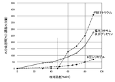
- Carboxylate Threshold Humidity Figure 4 is a graph showing the hygroscopic isotherms of sodium acetate, sodium propionate and sodium formate.
- the horizontal axis indicates the relative humidity
- the vertical axis indicates the moisture absorption rate.
- Carboxylate especially sodium salt of carboxylic acid, hydrates to form strong hydrate crystals with water molecules.
- the strong hydrate crystals formed are further hydrated and deliquesced to liquefy.
- a large amount of energy is required for further hydration of the formed strong hydrate crystals.
- it When it reaches a second relative humidity greater than the humidity, it deliquesces and liquefies. For example, as shown in FIG.
- sodium acetate forms strong hydrate crystals with water molecules at a relative humidity of about 70% RH or less, and the hydrate crystals form strong hydrate crystals at a relative humidity of about 80% RH. When it reaches , it deliquesces and liquefies.
- the hydrate crystal is a trihydrate.
- sodium propionate and sodium formate form strong hydrate crystals with water molecules at a relative humidity of about 50% RH or less, and the hydrate crystals deliquesce when the relative humidity reaches about 60% RH. to liquefy.
- carboxylates particularly sodium salts of carboxylic acids
- a threshold humidity that includes the relative humidity at which they form strong hydrate crystals with water molecules and/or the deliquescence point at which they deliquesce and liquefy, and the ambient air
- the relative humidity is lower than the threshold humidity, moisture absorption does not proceed beyond the formation of water molecules and hydrate crystals, and when the relative humidity of the surrounding air exceeds the threshold humidity, moisture absorption progresses and the water absorption rate increases. For example, as shown in FIG.
- the carboxylate has a threshold humidity that forms a boundary between the relative humidity at which moisture absorption hardly progresses and the relative humidity at which moisture absorption progresses rapidly.
- a threshold humidity that forms a boundary between the relative humidity at which moisture absorption hardly progresses and the relative humidity at which moisture absorption progresses rapidly.
- sodium acetate has a threshold humidity of approximately 70-80% RH.
- sodium propionate and sodium formate generally have a threshold humidity of 50-60% RH.
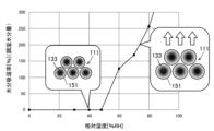
- FIG. 5 is a graph showing moisture absorption isotherms of a moisture absorbing component containing type B silica gel, a humidity conditioning component containing lithium chloride and glycerin, and a humidity conditioning component containing sodium formate as a main ingredient.
- the horizontal axis indicates the relative humidity
- the vertical axis indicates the moisture absorption rate.
- the moisture absorption rate of moisture-absorbing components and humidity-conditioning components that do not have a threshold humidity rises gradually as the relative humidity increases.
- the moisture absorption rate of the moisture absorbing component containing type B silica gel and the humidity controlling component containing lithium chloride and glycerin moderately increases as the relative humidity increases.
- the moisture absorption rate of the humidity conditioning component 132 having the threshold humidity is low within the range of relative humidity below the threshold humidity, and is steep within the range of relative humidity above the threshold humidity as the relative humidity increases. to be higher. For example, as shown in FIG.
- the moisture absorption rate of the humidity-conditioning component 132 containing sodium formate as a main ingredient is low in the relative humidity range of approximately 0 to 50% RH, and approximately 50 to 90% RH. In the humidity range, it rises sharply with increasing relative humidity. Therefore, the humidity conditioning component 132 has a threshold humidity that separates the relative humidity at which moisture absorption hardly progresses from the relative humidity at which moisture absorption progresses rapidly.
- the humidity-conditioning material containing sodium formate as a main component has a threshold humidity of approximately 50 to 60% RH that separates the relative humidity at which the moisture absorption hardly progresses from the relative humidity at which the moisture absorption progresses rapidly. have.
- a combination of two or more carboxylates may be included in the humidity conditioning component 132 .
- Additives as described above may be included in the humidity conditioning component 132 to affect the formation of hydrate crystals and adjust the threshold humidity and humidity conditioning characteristics.
- FIG. 6 is a diagram schematically illustrating release of a flavor component from a release material provided in the non-heating type flavor component release device of the first embodiment.
- the deliquescent component 151 is crystallized, and the flavor component 133 is incorporated inside the crystals of the deliquescent component 151. Therefore, release of the flavor component 133 from the release material 111 is suppressed.
- the deliquescence component 151 when the relative humidity is higher than the threshold humidity, the deliquescence component 151 is not crystallized, the crystal structure of the deliquescence component 151 is dissolved, and the flavor component 133 is released from the deliquescence component 151. Therefore, the flavor component 133 is slowly released from the release material 111 .
- the release material 111 can be given the function of an aromatic agent that triggers the development of flavor with changes in relative humidity.
- the relative humidity When the relative humidity is lower than the threshold humidity and the deliquescence component 151 is crystallized, the outer shell of the water absorbing material 141 hardens, and the water absorbing material 141 becomes a cloudy capsule. On the other hand, when the relative humidity is higher than the threshold humidity and the deliquescence component 151 is not crystallized, the water absorbing material 141 becomes transparent.
- FIGS. 7A, 7B, and 7C are diagrams schematically illustrating a production method of the release material provided in the non-heating flavor ingredient release device of the first embodiment.
- a water absorber 131 is prepared as shown in FIG. 7A.
- a humidity conditioning liquid 161 is prepared as illustrated in FIG. 7B. Also, the prepared water absorber 131 is immersed in the prepared humidity conditioning liquid 161 . The state in which the water absorber 131 is immersed in the humidity conditioning liquid 161 continues for several hours to one day, for example. As a result, the humidity control liquid 161 permeates the water absorber 131 to form the release material 111 . The permeated humidity control liquid 161 becomes the humidity control component 132 and the flavor component 133 provided in the release material 111 .
- the formed release material 111 is pulled up from the remaining humidity conditioning liquid 161 .
- the release material 111 pulled up is swollen, for example, 2 to 20 times.
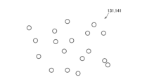
- FIG. 8 is a plan view schematically illustrating a first alternative example of the water absorber provided in the non-heating type flavor component release device of the first embodiment.
- the water absorber 131 illustrated in FIG. 8 has a powdery shape.
- the water absorber 131 illustrated in FIG. 8 has a diameter of several ⁇ m to several mm, for example.
- the water absorbing body 131 and the water absorbing material 141 have a filling rate such that a gap is formed between the powders through which the air flow AF can pass.
- FIG. 9 is a perspective view schematically illustrating a second example of the water absorber provided in the non-heating flavor component releasing device of the first embodiment.
- the water absorber 131 illustrated in FIG. 9 has a sheet-like shape.
- the water absorbing body 131 and the water absorbing material 141 can pass the airflow AF.
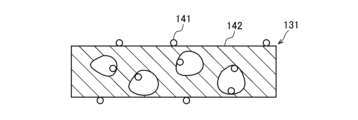
- FIG. 10 is a cross-sectional view schematically illustrating a third example of the water absorber provided in the non-heating flavor component releasing device of the first embodiment.
- a water absorbent body 131 illustrated in FIG. 10 includes a water absorbent material 141 and a carrier 142 .
- the water absorber 141 has a powdery or particulate shape.
- the carrier 142 is a porous body.
- a porous body is a foam.
- the water absorbing material 141 is carried on a carrier 142 .
- carrier 142 has high rigidity. Thereby, the emitting material 111 has a stable shape.
- the carrier 142 may be impregnated with the humidity control liquid.
- the water absorber 131 and the carrier 142 allow the airflow AF to pass through.
- FIG. 11 is a cross-sectional view schematically illustrating another example of a water absorber provided in the non-heating flavor component releasing device of the first embodiment.
- a water absorbent body 131 illustrated in FIG. 11 includes a water absorbent material 141 and a carrier 142 .
- the water absorber 141 has a powdery or particulate shape.
- the carrier 142 is a porous body.
- the porous body is non-woven fabric or woven fabric.
- the water absorbing material 141 is carried on a carrier 142 .
- carrier 142 has flexibility.
- the carrier 142 may be impregnated with the humidity control liquid.
- the water absorber 131 and the carrier 142 allow the airflow AF to pass through. Therefore, the water absorbing material 141 can efficiently come into contact with the air flow.
- FIG. 12 is a cross-sectional view schematically illustrating a fifth example of the water absorber provided in the non-heating flavor component releasing device of the first embodiment.
- a water absorbent body 131 illustrated in FIG. 12 includes a water absorbent material 141 and a carrier 142 .
- the water absorbent material 141 has a powdery or particulate shape.
- the carrier 142 is a ventilation member that allows an air flow in a direction perpendicular to the cross section shown in FIG.
- the ventilation member comprises, for example, non-woven fabric corrugated.
- the water absorbing material 141 is carried on a carrier 142 . According to the water absorbent body 131 illustrated in FIG.
- the water absorbent material 141 supported by the ventilation member can be brought into contact with the air efficiently by allowing the air flow to pass through the ventilation member, and the flavor component can be transferred to the water absorbent material 141 .
- 133 can be efficiently released.
- the carrier 142 may be impregnated with the humidity control liquid. The water absorber 131 and the carrier 142 allow the airflow AF to pass through. Therefore, the water absorbing material 141 can efficiently come into contact with the air flow.
- the water retainer 102 may be a water retainer that includes the water absorber 131 and the humidity conditioning component 132 and contains moisture.
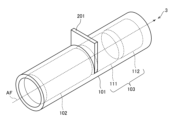
- FIG. 13 is a perspective view schematically illustrating the non-heating flavor component releasing device of the second embodiment.
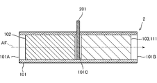
- FIG. 14 is a cross-sectional view schematically illustrating the non-heating type flavor component release device of the second embodiment.
- the non-heating flavor component release device 2 of the second embodiment includes a partition plate 201. As shown in FIGS. 13 and 14, the non-heating flavor component release device 2 of the second embodiment includes a partition plate 201. As shown in FIGS.
- the partition plate 201 is attached and detached inside the channel 101C.
- the partition plate 201 is attached and detached from the outside of the hollow casing 101 .
- the partition plate 201 is attached inside the channel 101C when the non-heating flavor component release device 2 is not used, and is removed from the channel 101C when the non-heating flavor component release device 2 is used.
- the partition plate 201 separates the water retaining body 102 and the emitting body 103 when installed in the channel 101C, and does not separate the water retaining body 102 and the emitting body 103 when removed from the channel 101C. This can prevent the air flow AF having a high relative humidity from passing through the release body 103 containing the crystallized deliquescent component 151 when the non-heating flavor component release device 2 is not in use. .
- the water retaining body 102 is a water retaining body that includes a water absorbing body 131 and a humidity conditioning component 132 and contains moisture.
- the water retainer 102 may be a release material that includes a water absorber 131, a humidity control component 132 and a flavor component 133 and releases the flavor component 133 into the air flow AF.
- the release material 111 is the first release material
- the water retainer 102 is the second release material
- the flavor component 133 released by the release material 111 is the first flavor component
- the flavoring component released by water retainer 102 is the second flavoring component.
- the water holding body 102 has a relative humidity higher than the threshold humidity of the water holding body 102 in the initial state. Therefore, the water holding body 102 contains a deliquescent component 151 that is not crystallized. Also, the water holding body 102 has a high relative humidity, preferably 70% RH or more, more preferably 80% RH or more and 100% RH or less. This can prevent the relative humidity of the water retaining body 102 from becoming lower than the relative humidity of the air around the water retaining body 102 and the water retaining body 102 absorbing moisture without releasing moisture. As a result, the operation of supplying water to the water retaining body 102 can be eliminated.
- the water retaining body 102 allows the airflow AF to pass through and releases moisture and the second flavor component into the airflow AF to generate an airflow AF having a high relative humidity and containing the second flavor component.
- the emitter 103 passes the generated airflow AF, absorbs moisture contained in the passing airflow AF, and absorbs moisture and the first moisture in the passing airflow AF after the relative humidity becomes higher than the threshold humidity. Flavoring components are released to produce an airflow AF having a high relative humidity and containing a first flavoring component and a second flavoring component.
- FIG. 15 shows changes in the amount of the first flavor component and the second flavor component released by the non-heating type flavor component release device of the second embodiment, depending on the elapsed time from the start of air flow generation.
- the release amount of the second flavor component released by the water retainer 102 is large immediately after the generation of the airflow AF is started.
- the release amount of the first flavor component produced by the emitter 103 was small immediately after the generation of the air flow AF was started, and the relative humidity of the air around the emitter 103 became higher than the threshold humidity. become larger over time.
- the non-heating type flavor component release device 2 releases the second flavor component immediately after the generation of the airflow AF is started, and a certain amount of time elapses after the generation of the airflow AF is started. releasing the first flavor component from.
- the user can enjoy changes in the flavor expressed by the first flavor component and the second flavor component over time, the mixing of the flavor expressed by the first flavor component and the second flavor component, and the like. .
- FIG. 16 is a perspective view schematically illustrating the non-heating type flavor component releasing device of the third embodiment.
- FIG. 17 is a cross-sectional view schematically illustrating a non-heating flavor ingredient release device of the third embodiment.
- the releasing body 103 comprises a plurality of releasing materials 111 and 112.
- the plurality of emitting materials 111 and 112 are two emitting materials.
- the plurality of emitting materials 111 and 112 may be three or more emitting materials.
- a plurality of release materials 111 and 112 are arranged in the direction in which the channel 101C extends. Thereby, the plurality of release materials 111 and 112 are arranged in the direction in which the airflow AF flows.
- a plurality of release materials 111 and 112 release a plurality of flavor components into the airflow AF, respectively.
- Each release material of the plurality of release materials 111 and 112 has a threshold humidity, releases the flavor component of each release material when the relative humidity is above the threshold humidity, and releases the flavor component of each release material when the relative humidity is below the threshold humidity. It does not release the flavor components of each release material.
- the threshold humidity values of the plurality of emitting materials 111 and 112 are different from each other. Desirably, the threshold humidity of the release materials contained in the plurality of release materials 111 and 112 increases toward the downstream side of the air flow AF.
- Each emitting material of the plurality of emitting materials 111 and 112 has a relative humidity lower than the threshold humidity of each emitting material in the initial state.
- the water retaining body 102 allows the air flow AF to pass through and releases moisture into the air flow AF to generate an air flow AF having a high relative humidity.
- the release material 111 allows the generated airflow AF to pass through, absorbs moisture contained in the airflow AF to be passed through, and absorbs the moisture and the first moisture in the airflow AF to be passed after the relative humidity becomes higher than the threshold humidity.
- a flavoring component is released to produce an airflow AF having a high relative humidity and containing a first flavoring component.
- the release material 112 passes the generated air flow AF, absorbs moisture contained in the passing air flow AF, and absorbs moisture and the second moisture in the passing air flow AF after the relative humidity becomes higher than the threshold humidity. Flavoring components are released to produce an airflow AF having a high relative humidity and containing a first flavoring component and a second flavoring component.
- the moisture absorption of the water released by the water retaining body 102 progresses from the upstream side of the airflow AF toward the downstream side of the airflow AF. Therefore, as described above, the release of the flavor component proceeds from the upstream side of the airflow AF toward the downstream side of the airflow AF, whereby the flavor component can be efficiently carried by the airflow AF.
- FIG. 18 shows the amount of the first flavor component, the second flavor component and the third flavor component released by the non-heating type flavor component release device of the third embodiment when the generation of the air flow is started.
- 10 is a graph showing an example of change with elapsed time from .
- the horizontal axis represents the elapsed time
- the vertical axis represents the release amount.
- the third flavor component is released by the water retainer 102 when the water retainer 102 is a release material that includes the water absorber 131, the humidity conditioning component 132, and the flavor component 133 and releases the flavor component 133 into the airflow AF. It is the flavor component 133 .
- the release amount of the third flavor component released by the water retainer 102 is large immediately after the generation of the airflow AF is started.
- the release amount of the first flavor component released by the release material 111 on the upstream side is small immediately after the generation of the airflow AF is started, and the relative humidity of the air around the release material 111 is higher than the threshold humidity. It gets bigger when it grows up.
- the release amount of the second flavor component released by the release material 112 on the downstream side is small immediately after the generation of the air flow AF is started, and the relative humidity of the air around the release material 112 is higher than the threshold humidity. It gets bigger when it grows up.
- the non-heating type flavor component release device 3 releases the third flavor component immediately after the start of generation of the airflow AF, and after a certain amount of time has passed since the start of generation of the airflow AF.
- a first flavor component and a second flavor component are released, and a third release component is released after releasing the second flavor component.
- the change in the flavor expressed by the first flavor component, the second flavor component, and the third flavor component over time, and the flavor expressed by the first flavor component, the second flavor component, and the third flavor component The user can be entertained by mixing flavors and the like.
- the human sense of smell adapts to the flavor and becomes less sensitive to the flavor. Therefore, by sequentially exposing a person to the flavors expressed by the third flavor component, the first flavor component and the second flavor component, the human sense of smell can perceive the flavor over a long period of time. .
- FIG. 19 is a perspective view schematically illustrating a first alternative example of a plurality of releasing materials provided in the non-heating flavor component releasing device of the third embodiment.
- a plurality of release materials 111 and 112 illustrated in FIG. 19 are arranged linearly in a direction perpendicular to the direction in which the channel 101C extends.
- the plurality of release materials 111 and 112 are linearly arranged in a direction perpendicular to the direction in which the airflow AF flows.
- the threshold humidity of the plurality of emission materials 111 and 112 may be the same, and even if the threshold humidity of the plurality of emission materials 111 and 112 are different, the threshold humidity of any of the plurality of emission materials 111 and 112 Humidity can be high.
- the absorbers 131 and absorbers 141 of the plurality of release materials 111 and 112 may be the same or different in the forms shown in FIGS.
- the surface area of the water absorber 131 and the water absorbent material 141 increases, the efficiency of contact with the air flow improves, and the flavor component 133 can be released efficiently.
- the release of the flavor component 133 can be given a temporal width.
- FIG. 20 is a perspective view schematically illustrating a second example of a plurality of release materials provided in the non-heating flavor component release device of the third embodiment.
- a plurality of release materials 111 and 112 illustrated in FIG. 20 are arranged concentrically in a direction perpendicular to the direction in which the channel 101C extends.
- the plurality of release materials 111 and 112 are arranged concentrically in a direction perpendicular to the direction in which the airflow AF flows.
- the threshold humidity of the plurality of emission materials 111 and 112 may be the same, and even if the threshold humidity of the plurality of emission materials 111 and 112 are different, the threshold humidity of any of the plurality of emission materials 111 and 112 Humidity can be high.
- the absorbers 131 and absorbers 141 of the plurality of release materials 111 and 112 may be the same or different in the forms shown in FIGS.
- the surface area of the water absorber 131 and the water absorbent material 141 increases, the efficiency of contact with the air flow improves, and the flavor component 133 can be released efficiently.
- the release of the flavor component 133 can be given a temporal width.
- the flavor component released by one of the plurality of release materials 111 and 112 is not pass through the other. Therefore, the flavor component released by one of the plurality of release materials 111 and 112 is adsorbed by the other three of the plurality of release materials 111 and 112, and the flavor component released by one of the plurality of release materials 111 and 112 becomes It is possible to suppress the weakening of the flavor that is expressed. Also, the flavor components released by the plurality of release materials 111 and 112 can be efficiently carried by the air flow AF.
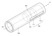
- FIG. 21 is a perspective view schematically illustrating the non-heating flavor component releasing device of the fourth embodiment.
- the ejector 103 is composed of a plurality of releasing Materials 111 and 112 are provided.
- the hollow casing 101 has a transparent window 401 .
- the transparent window 401 does not transmit the airflow AF, but transmits light.
- the emitter 103 is arranged along the transparent window 401 . Thereby, the emitter 103 is visible from the outside of the hollow casing 101 through the transparent window 401 . This makes it possible to grasp the appearance of the emitter 103, and when the appearance of the emitter 103 indicates whether or not the flavor component 133 can be released, the non-heating type flavor component release device 1 can release the flavor component 133. It is possible to indicate whether or not the release is possible.
- the relative humidity when the relative humidity is lower than the threshold humidity and the deliquescence component 151 is crystallized, the outer shell of the water absorbing material 141 hardens, and the water absorbing material 141 becomes a cloudy capsule.
- the relative humidity when the relative humidity is higher than the threshold humidity and the deliquescence component 151 is not crystallized, the water absorbing material 141 becomes transparent.
- Such a change in appearance of the water absorbing material 141 appears as a change in appearance of the releasing material 111 .
- the change in appearance of the release material 111 can be visually recognized from the outside of the non-heating type flavor component release device 4 through the transparent window 401 . Thereby, it is possible to indicate whether or not the flavor component 133 can be released by the release material 111, and it is possible to indicate the end of the sustained release of the flavor component 133.
- the release materials 111 and 112 may contain pigments. Thereby, it is possible to more clearly grasp whether or not the deliquescent component 151 is crystallized.
- the dye is desirably a food dye. As a result, even when the coloring matter is released together with the flavoring ingredient, the highly safe food coloring matter is emitted, and the non-heating flavoring ingredient releasing device 4 that is highly safe for the user can be provided.
- Food dyes are, for example, from annatto dyes, turmeric dyes, caramel dyes, gardenia blue dyes, gardenia red dyes, gardenia yellow dyes, cochineal dyes, red yeast dyes, safflower red dyes, safflower yellow dyes, anthocyanin dyes, paprika dyes and flavonoid dyes. At least one selected from the group consisting of
- FIG. 22 is a perspective view schematically illustrating a non-heating flavor inhaler of a fifth embodiment.
- FIG. 23 is a cross-sectional view schematically illustrating the non-heating flavor inhaler of the fifth embodiment.
- the non-heating flavor inhaler 5 of the fifth embodiment includes a non-heating flavor component releasing device 501 and a cylindrical holder 502. As shown in FIGS. 22 and 23, the non-heating flavor inhaler 5 of the fifth embodiment includes a non-heating flavor component releasing device 501 and a cylindrical holder 502. As shown in FIGS. 22 and 23, the non-heating flavor inhaler 5 of the fifth embodiment includes a non-heating flavor component releasing device 501 and a cylindrical holder 502. As shown in FIGS.
- the non-heating flavor component release device 501 includes the non-heating flavor component release device 1 of the first embodiment, the non-heating flavor component release device 2 of the second embodiment, and the non-heating flavor component release device of the third embodiment. It is the non-heating flavor component release device 4 of the third or fourth embodiment, or a non-heating flavor component release device modified from any of these.
- the non-heating flavor component release device 501 is a cartridge replaceably attachable to and detachable from the tubular holder 502 .
- the tubular holder 502 has a tubular shape. For this reason, the tubular holder 502 is formed with an inlet 502A, an outlet 502B, and a housing space 502C.
- the accommodation space 502C extends from the entrance 502A to the exit 502B. Thereby, airflow AF enters the accommodation space 502C through the inlet 502A, is guided by the accommodation space 502C from the inlet 502A to the outlet 502B, and exits the accommodation space 502C through the outlet 502B.
- the accommodation space 502C accommodates the non-heating flavor component release device 501.
- the cylindrical holder 502 has a mouthpiece 511 .
- the mouthpiece 511 is at one end of the tubular holder 502 .
- the mouthpiece 511 is formed with an outlet 502B.
- a user of the non-heating flavor inhaler 5 sucks the mouthpiece 511 to generate an air flow AF.
- This allows the user to inhale the airflow AF containing the flavor component. Therefore, unlike combustible cigarettes and heat-not-burn cigarettes, it is possible to enjoy an entertainment similar to smoking without heating.
- the flavor component does not contain the flavor component of tobacco, it is possible to realize mental and physical comfort, health and beauty by providing entertainment that imitates smoking with a flavor component that is not a tobacco flavor component. can.
- various flavor components can be enjoyed.
- FIG. 24 is a perspective view schematically illustrating a non-heating type sustained flavor release device of a sixth embodiment.
- FIG. 25 is a cross-sectional view schematically illustrating the non-heating type sustained flavor release device of the sixth embodiment.
- the non-heating type sustained flavor release device 6 of the sixth embodiment includes a non-heating type flavor component release device 601, a cylindrical holder 602 and a blower device 603.
- the non-heating flavor component release device 601 includes the non-heating flavor component release device 1 of the first embodiment, the non-heating flavor component release device 2 of the second embodiment, and the non-heating flavor component release device of the third embodiment. It is the non-heating flavor component release device 4 of the third or fourth embodiment, or a non-heating flavor component release device modified from any of these.
- the non-heating flavor component release device 601 is a cartridge replaceably attachable to and detachable from the tubular holder 602 .
- the tubular holder 602 has a tubular shape. For this reason, the tubular holder 602 is formed with an inlet 602A, an outlet 602B, and an accommodation space 602C.
- the accommodation space 602C extends from the entrance 602A to the exit 602B. Thereby, airflow AF enters the receiving space 602C through the inlet 602A, is guided by the receiving space 602C from the inlet 602A to the outlet 602B, and exits the receiving space 602C through the outlet 602B.
- the accommodation space 602C accommodates the non-heating flavor component release device 601.
- the blower 603 is arranged along the inlet 602A.
- a blower 603 generates an air flow AF.
- a blower 603 may be positioned along the outlet 602B.
- the airflow AF containing the flavor component can be emitted from the outlet 602B, and the flavor component can be gradually released.
- the non-heating type flavor component release device 601 by exchanging the non-heating type flavor component release device 601, various flavor components can be enjoyed.
- the present disclosure is not limited to the above embodiments, but has substantially the same configuration, the same effect, or the same purpose as the configuration shown in the above embodiment. can be replaced with
Landscapes
- Disinfection, Sterilisation Or Deodorisation Of Air (AREA)
- Solid-Sorbent Or Filter-Aiding Compositions (AREA)
Priority Applications (3)
| Application Number | Priority Date | Filing Date | Title |
|---|---|---|---|
| US18/574,921 US20240298717A1 (en) | 2021-07-26 | 2022-05-18 | Non-heating type flavor component emission device, non-heating type flavor inhaler, and non-heating type flavor sustained-release device |
| JP2023538291A JP7691498B2 (ja) | 2021-07-26 | 2022-05-18 | 非加熱型香味成分放出装置、非加熱型香味吸引器及び非加熱型香味徐放装置 |
| CN202280044020.1A CN117529249A (zh) | 2021-07-26 | 2022-05-18 | 非加热型香味成分释放装置、非加热型香味吸取器及非加热型香味缓释装置 |
Applications Claiming Priority (2)
| Application Number | Priority Date | Filing Date | Title |
|---|---|---|---|
| JP2021121774 | 2021-07-26 | ||
| JP2021-121774 | 2021-07-26 |
Publications (1)
| Publication Number | Publication Date |
|---|---|
| WO2023007912A1 true WO2023007912A1 (ja) | 2023-02-02 |
Family
ID=85086479
Family Applications (1)
| Application Number | Title | Priority Date | Filing Date |
|---|---|---|---|
| PCT/JP2022/020598 Ceased WO2023007912A1 (ja) | 2021-07-26 | 2022-05-18 | 非加熱型香味成分放出装置、非加熱型香味吸引器及び非加熱型香味徐放装置 |
Country Status (4)
| Country | Link |
|---|---|
| US (1) | US20240298717A1 (https=) |
| JP (1) | JP7691498B2 (https=) |
| CN (1) | CN117529249A (https=) |
| WO (1) | WO2023007912A1 (https=) |
Citations (2)
| Publication number | Priority date | Publication date | Assignee | Title |
|---|---|---|---|---|
| JPS62501050A (ja) * | 1984-11-01 | 1987-04-30 | アクチ−ボラゲツト レオ | 本質的に純粋なニコチンを解放するたばこ組成物、方法および装置 |
| WO2014136872A1 (ja) * | 2013-03-08 | 2014-09-12 | 日本たばこ産業株式会社 | 非燃焼型香味吸引器 |
Family Cites Families (11)
| Publication number | Priority date | Publication date | Assignee | Title |
|---|---|---|---|---|
| US4934524A (en) * | 1988-09-19 | 1990-06-19 | Brown & Williamson Tobacco Corporation | Package for storing moisture laden articles |
| JP4636911B2 (ja) | 2005-03-16 | 2011-02-23 | テルモ株式会社 | 酸素濃縮装置 |
| GB0710776D0 (en) * | 2007-06-05 | 2007-07-18 | British American Tobacco Co | Heatable humidifying device for use with tobacco products |
| CN103179869B (zh) * | 2010-08-20 | 2016-05-18 | 日本烟草产业株式会社 | 非加热型香烟香精抽吸器 |
| JP2015107056A (ja) * | 2012-03-16 | 2015-06-11 | 日本たばこ産業株式会社 | 非加熱型香味吸引器 |
| EP3369480B1 (en) * | 2012-10-03 | 2020-01-01 | Nippon Shokubai Co., Ltd. | Water absorbing agent |
| JP6266100B2 (ja) * | 2014-05-09 | 2018-01-24 | シャープ株式会社 | 調湿装置 |
| US20170007594A1 (en) * | 2015-07-08 | 2017-01-12 | Niconovum Usa,Inc | Therapeutic composition and configuration |
| CN204861143U (zh) | 2015-07-15 | 2015-12-16 | 江苏省产品质量监督检验研究院 | 一种三元香烟过滤嘴 |
| CN111491525B (zh) | 2017-12-27 | 2022-04-26 | 日本烟草产业株式会社 | 吸烟物品 |
| JP6890864B2 (ja) | 2018-05-17 | 2021-06-18 | 株式会社東亜産業 | 芳香カートリッジ |
-
2022
- 2022-05-18 JP JP2023538291A patent/JP7691498B2/ja active Active
- 2022-05-18 WO PCT/JP2022/020598 patent/WO2023007912A1/ja not_active Ceased
- 2022-05-18 CN CN202280044020.1A patent/CN117529249A/zh active Pending
- 2022-05-18 US US18/574,921 patent/US20240298717A1/en active Pending
Patent Citations (2)
| Publication number | Priority date | Publication date | Assignee | Title |
|---|---|---|---|---|
| JPS62501050A (ja) * | 1984-11-01 | 1987-04-30 | アクチ−ボラゲツト レオ | 本質的に純粋なニコチンを解放するたばこ組成物、方法および装置 |
| WO2014136872A1 (ja) * | 2013-03-08 | 2014-09-12 | 日本たばこ産業株式会社 | 非燃焼型香味吸引器 |
Also Published As
| Publication number | Publication date |
|---|---|
| US20240298717A1 (en) | 2024-09-12 |
| JP7691498B2 (ja) | 2025-06-11 |
| JPWO2023007912A1 (https=) | 2023-02-02 |
| CN117529249A (zh) | 2024-02-06 |
Similar Documents
| Publication | Publication Date | Title |
|---|---|---|
| KR102546746B1 (ko) | 에어로졸 생성 장치 | |
| JP7402296B2 (ja) | エアロゾル前駆体組成物の貯蔵を改善させた電子喫煙物品 | |
| JP6732724B2 (ja) | メントールを含む喫煙物品 | |
| EP3429380B1 (en) | Multi-layered micro-beads for electronic cigarettes | |
| CN107404939B (zh) | 用于使来自非可燃吸烟制品的气溶胶功能化的装置 | |
| JP7034945B2 (ja) | 液体エアロゾル形成基体および可燃性熱発生要素を備えた加熱式エアロゾル発生物品 | |
| JP7088595B2 (ja) | シガレット及びシガレット用のエアロゾル生成装置 | |
| JP5831885B2 (ja) | 無煙の煙草代用製品 | |
| JP3744953B2 (ja) | 改良されたタバコフィルター | |
| US9943107B2 (en) | Cartomizer flavor enhancement | |
| JP7339958B2 (ja) | 溶融可能な要素を有するエアロゾル発生物品 | |
| CA1259181A (en) | Tobacco compositions, method and device for releasing essentially pure nicotine | |
| JPWO2004089126A1 (ja) | ニコチン吸引パイプ及びニコチンホルダ | |
| CN109414071A (zh) | 香味吸入器及燃烧式热源的制造方法 | |
| JP7395620B2 (ja) | エアロゾルの発生 | |
| JPH062164B1 (ja) | 喫煙用物品 | |
| JP2014506468A (ja) | 無煙煙草、葉巻、またはパイプ | |
| JP2020501539A (ja) | 複数のエアロゾル形成基体および液体移動要素を備えるエアロゾル発生システム | |
| JP2009504175A (ja) | 喫煙物品のための液体放出装置 | |
| KR20240090861A (ko) | 저 저항 기류 경로를 갖는 에어로졸 발생 물품 | |
| CN217547246U (zh) | 一种气溶胶生成制品 | |
| JP7356087B2 (ja) | エアロゾル生成製品 | |
| TW200911140A (en) | Cigarette | |
| KR102525022B1 (ko) | 흡연물품용 니코틴 함유물질 및 이를 포함하는 비연소형 흡연물품과 흡연물품용 카트리지 | |
| WO2023007912A1 (ja) | 非加熱型香味成分放出装置、非加熱型香味吸引器及び非加熱型香味徐放装置 |
Legal Events
| Date | Code | Title | Description |
|---|---|---|---|
| 121 | Ep: the epo has been informed by wipo that ep was designated in this application |
Ref document number: 22848993 Country of ref document: EP Kind code of ref document: A1 |
|
| WWE | Wipo information: entry into national phase |
Ref document number: 2023538291 Country of ref document: JP |
|
| WWE | Wipo information: entry into national phase |
Ref document number: 202280044020.1 Country of ref document: CN |
|
| NENP | Non-entry into the national phase |
Ref country code: DE |
|
| 122 | Ep: pct application non-entry in european phase |
Ref document number: 22848993 Country of ref document: EP Kind code of ref document: A1 |