WO2023007854A1 - 容器 - Google Patents
容器 Download PDFInfo
- Publication number
- WO2023007854A1 WO2023007854A1 PCT/JP2022/014874 JP2022014874W WO2023007854A1 WO 2023007854 A1 WO2023007854 A1 WO 2023007854A1 JP 2022014874 W JP2022014874 W JP 2022014874W WO 2023007854 A1 WO2023007854 A1 WO 2023007854A1
- Authority
- WO
- WIPO (PCT)
- Prior art keywords
- container
- rfid tag
- bottom plate
- thickness
- plate portion
- Prior art date
Links
- 239000002184 metal Substances 0.000 claims abstract description 21
- 229910052751 metal Inorganic materials 0.000 claims abstract description 21
- 238000002955 isolation Methods 0.000 claims description 23
- 230000004308 accommodation Effects 0.000 claims description 10
- 125000006850 spacer group Chemical group 0.000 claims description 4
- 238000004519 manufacturing process Methods 0.000 description 20
- 230000005674 electromagnetic induction Effects 0.000 description 4
- 238000000034 method Methods 0.000 description 4
- 229910052759 nickel Inorganic materials 0.000 description 4
- 239000000853 adhesive Substances 0.000 description 3
- 230000001070 adhesive effect Effects 0.000 description 3
- 239000003985 ceramic capacitor Substances 0.000 description 3
- 229910052802 copper Inorganic materials 0.000 description 3
- 230000004048 modification Effects 0.000 description 3
- 238000012986 modification Methods 0.000 description 3
- 230000000694 effects Effects 0.000 description 2
- 101100480512 Caenorhabditis elegans tag-51 gene Proteins 0.000 description 1
- 238000010586 diagram Methods 0.000 description 1
- 230000012447 hatching Effects 0.000 description 1
- 238000007689 inspection Methods 0.000 description 1
- 229910052697 platinum Inorganic materials 0.000 description 1
- 229920000515 polycarbonate Polymers 0.000 description 1
- 239000004417 polycarbonate Substances 0.000 description 1
- 239000011347 resin Substances 0.000 description 1
- 229920005989 resin Polymers 0.000 description 1
- 230000000630 rising effect Effects 0.000 description 1
- 238000000926 separation method Methods 0.000 description 1
- 229910052709 silver Inorganic materials 0.000 description 1
- 230000000087 stabilizing effect Effects 0.000 description 1
- 229910052718 tin Inorganic materials 0.000 description 1
Images


Classifications
-
- B—PERFORMING OPERATIONS; TRANSPORTING
- B65—CONVEYING; PACKING; STORING; HANDLING THIN OR FILAMENTARY MATERIAL
- B65D—CONTAINERS FOR STORAGE OR TRANSPORT OF ARTICLES OR MATERIALS, e.g. BAGS, BARRELS, BOTTLES, BOXES, CANS, CARTONS, CRATES, DRUMS, JARS, TANKS, HOPPERS, FORWARDING CONTAINERS; ACCESSORIES, CLOSURES, OR FITTINGS THEREFOR; PACKAGING ELEMENTS; PACKAGES
- B65D25/00—Details of other kinds or types of rigid or semi-rigid containers
- B65D25/20—External fittings
-
- B—PERFORMING OPERATIONS; TRANSPORTING
- B65—CONVEYING; PACKING; STORING; HANDLING THIN OR FILAMENTARY MATERIAL
- B65D—CONTAINERS FOR STORAGE OR TRANSPORT OF ARTICLES OR MATERIALS, e.g. BAGS, BARRELS, BOTTLES, BOXES, CANS, CARTONS, CRATES, DRUMS, JARS, TANKS, HOPPERS, FORWARDING CONTAINERS; ACCESSORIES, CLOSURES, OR FITTINGS THEREFOR; PACKAGING ELEMENTS; PACKAGES
- B65D85/00—Containers, packaging elements or packages, specially adapted for particular articles or materials
- B65D85/30—Containers, packaging elements or packages, specially adapted for particular articles or materials for articles particularly sensitive to damage by shock or pressure
- B65D85/38—Containers, packaging elements or packages, specially adapted for particular articles or materials for articles particularly sensitive to damage by shock or pressure for delicate optical, measuring, calculating or control apparatus
-
- G—PHYSICS
- G06—COMPUTING; CALCULATING OR COUNTING
- G06K—GRAPHICAL DATA READING; PRESENTATION OF DATA; RECORD CARRIERS; HANDLING RECORD CARRIERS
- G06K19/00—Record carriers for use with machines and with at least a part designed to carry digital markings
- G06K19/06—Record carriers for use with machines and with at least a part designed to carry digital markings characterised by the kind of the digital marking, e.g. shape, nature, code
- G06K19/067—Record carriers with conductive marks, printed circuits or semiconductor circuit elements, e.g. credit or identity cards also with resonating or responding marks without active components
- G06K19/07—Record carriers with conductive marks, printed circuits or semiconductor circuit elements, e.g. credit or identity cards also with resonating or responding marks without active components with integrated circuit chips
- G06K19/077—Constructional details, e.g. mounting of circuits in the carrier
-
- H—ELECTRICITY
- H01—ELECTRIC ELEMENTS
- H01L—SEMICONDUCTOR DEVICES NOT COVERED BY CLASS H10
- H01L21/00—Processes or apparatus adapted for the manufacture or treatment of semiconductor or solid state devices or of parts thereof
-
- B—PERFORMING OPERATIONS; TRANSPORTING
- B65—CONVEYING; PACKING; STORING; HANDLING THIN OR FILAMENTARY MATERIAL
- B65D—CONTAINERS FOR STORAGE OR TRANSPORT OF ARTICLES OR MATERIALS, e.g. BAGS, BARRELS, BOTTLES, BOXES, CANS, CARTONS, CRATES, DRUMS, JARS, TANKS, HOPPERS, FORWARDING CONTAINERS; ACCESSORIES, CLOSURES, OR FITTINGS THEREFOR; PACKAGING ELEMENTS; PACKAGES
- B65D2585/00—Containers, packaging elements or packages specially adapted for particular articles or materials
- B65D2585/68—Containers, packaging elements or packages specially adapted for particular articles or materials for machines, engines, or vehicles in assembled or dismantled form
- B65D2585/86—Containers, packaging elements or packages specially adapted for particular articles or materials for machines, engines, or vehicles in assembled or dismantled form for electrical components
Definitions
- the present invention relates to containers equipped with RFID tags.
- the communication waves emitted from the reader's antenna may interfere with the reflected waves reflected by the metal, preventing stable communication.
- An object of the present invention is to provide a container that can perform stable communication with an RFID tag even if the contents contain metal.
- a container according to the present invention is an insulating container that accommodates a content and is placed on a predetermined placement surface, and has a surface with which the content can come into contact and a back surface that faces the placement surface.
- the bottom plate portion has a contact surface that contacts the mounting surface, and a separating portion having a thickness X1 of 0.5 mm or more and 10 mm or less, which is arranged between the RFID tag and the surface.
- stable communication can be performed with the RFID tag even if the contained object is metal or contains metal.
- FIG. 4 is a side cross-sectional view schematically showing a state in which the container according to the embodiment is placed on a table having an RFID tag; It is a back view of the container which concerns on embodiment.
- 1 is a block diagram showing the configuration of an RFID tag according to an embodiment;
- FIG. 2 is a partially enlarged view of FIG. 1 showing the isolation part according to the embodiment;
- FIG. 11 is a cross-sectional view showing a modification of the isolation part;
- 1 is a plan view conceptually showing a manufacturing system using a container according to an embodiment;
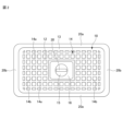
- FIG. 1 schematically shows a side cross section of a container 1 according to an embodiment.
- FIG. 2 shows the back side of container 1 .
- the container 1 accommodates a large number of electronic components M as objects to be accommodated in a loose state.
- the container 1 is mounted on the mounting surface 51 of the predetermined table 50 .
- the electronic component M may be accommodated in the container 1 in a bagged state.
- the container 1 is molded from an insulating resin such as polycarbonate.
- the electronic component M is, for example, a small electronic component such as a multilayer ceramic capacitor or an inductor, and is particularly suitable for a chip-like small electronic component containing metal.
- a multilayer ceramic capacitor is composed of a multilayer laminate in which an internal electrode layer mainly composed of a metal such as Ni or Cu is sandwiched between dielectric layers, and a surface of a metal such as Cu, Ni, Ag, Pt, or Au. It has an external electrode plated with Ni, Sn, or the like, and contains a metal.
- the container 1 is a substantially rectangular parallelepiped box.
- the container 1 includes a flat rectangular bottom plate portion 10, side wall portions 20 rising from four edges of the bottom plate portion 10 and surrounding the bottom plate portion 10, an opening portion 21 opening upward, and the bottom plate portion 10. and an RFID tag 30 .
- a lid 22 detachable from the container 1 may close the opening 21 of the container 1 to hermetically seal the electronic component M in the container 1 .
- the side wall portions 20 extend in the longitudinal direction of the container 1 (horizontal direction in FIGS. 1 and 2) and face each other in the width direction (front and back direction of the paper surface of FIGS. 1 and 2), and a pair of first side wall portions 20a; A pair of second side wall portions 20b extending in the width direction of the container 1 and opposed in the longitudinal direction are included.
- FIG. 1 only one first side wall portion 20a is shown.
- the second side wall portion 20b is slanted so as to fall slightly outward from the container 1 as it goes from its lower end to its upper end.
- the first side wall portion 20a is inclined like the second side wall portion 20b or perpendicular to the bottom plate portion 10 .
- the first side wall portion 20a and the second side wall portion 20b may have any shape including whether or not they are inclined, and are not limited to the embodiment.
- the dimensions of the container 1 are approximately 200 to 400 mm in length, 100 to 300 mm in width, and 50 to 150 mm in height.
- the bottom plate portion 10 supports a large number of electronic components M accommodated in the container 1.
- the bottom plate portion 10 includes an inner flat surface 11 with which the electronic component M can come into contact, and an outer rear surface 12 facing the mounting surface 51 .
- the rear surface 12 of the bottom plate portion 10 has a rectangular edge 13 on its outermost periphery, and has grid-like ribs 14 inside the edge 13 .
- Both the edge portion 13 and the rib 14 are protrusions that protrude toward the rear surface 12 side.
- the edge portion 13 and the ribs 14 improve the rigidity of the bottom plate portion 10 .
- the ribs 14 include a plurality of first ribs 14a extending in the longitudinal direction and a plurality of second ribs 14b extending in the width direction perpendicular to the first ribs 14a.
- No rib 14 is formed in the central portion of the back surface 12 of the bottom plate portion 10, and a housing space 15 consisting of a circular recess is formed in the central portion.
- a rectangular convex portion 16 is formed as a spacer portion around the accommodation space 15 . That is, a housing space 15 is formed in the central portion of the convex portion 16 .
- the RFID tag 30 is arranged on the rear surface 12 side of the bottom plate portion 10 while being housed in the housing space 15 .
- Various types of information are written and stored in the RFID tag 30 .
- various information contained in the RFID tag 30 is read by an RFID reader 60.
- FIG. RFID reader 60 includes an antenna section 61 arranged on mounting surface 51 of table 50 and a control section 62 connected to antenna section 61 .
- Information read by the RFID reader 60 is wirelessly transmitted to the management unit 65 .
- the management unit 65 processes the received information.
- the information contained in the RFID tag 30 is arbitrary, but includes, for example, electronic component information related to the electronic component M, a unique ID associated with the electronic component M, and the like.
- the electronic component information includes, for example, the lot number of the electronic component M, product and type information related to the electronic component M, inspection number of the electronic component M, and the like.
- the RFID tag 30 may contain information about the container 1 .
- the information about the container 1 includes, for example, the number of electronic components M housed in the container 1, the ID number of the container 1, and the like.
- the RFID tag 30 includes a storage section 31 that stores various information and an antenna section 32 for communication.
- the RFID tag 30 of the embodiment does not have a power source and is a passive type that converts radio waves (signals) received from the antenna section 61 of the RFID reader 60 into power, the configuration of the RFID tag 30 is not limited to this.
- the RFID tag 30 of the embodiment has an elongated sheet-like shape as a whole, and is attached, for example, to the upper surface of the accommodation space 15 via an adhesive. Note that the RFID tag 30 may be fixed with a cover that covers the RFID tag 30 .
- the adhesive may be preliminarily placed on one side of the RFID tag 30 so that the RFID tag 30 is an adhesive seal, or it may be applied to one side of the RFID tag 30 at the time of sticking.
- the shape of the RFID tag 30 is not limited to this, and may be circular, square, triangular, or the like.
- the bottom plate section 10 has an isolation section 17 arranged between the RFID tag 30 and the surface 11 .
- the isolation part 17 separates the RFID tag 30 and the surface 11 by a distance X1 in the height direction.
- the isolation portion 17 is the portion of the bottom plate portion 10 where the RFID tag 30 is arranged, that is, the thickness portion of the bottom plate portion 10 above the accommodation space 15, and the thickness of the isolation portion 17 is X1.
- the thickness X1 of the isolation portion 17 is the same as the thickness of the bottom plate portion 10 .
- the isolation part 17, which is a part of the bottom plate part 10 is particularly indicated by cross hatching.
- FIG. 5 is also the same.
- the accommodation space 15 in which the RFID tag 30 is arranged is arranged between the isolation portion 17 of the bottom plate portion 10 and the mounting surface 51, and the distance in the height direction between the RFID tag 30 and the mounting surface 51 is is X2.
- the distance X2 is the distance in the height direction between the RFID tag 30 and the contact surface 16a, which is the rear surface of the protrusion 16 that contacts the mounting surface 51.
- the convex portion 16 forms the accommodation space 15 between the isolation portion 17 and the mounting surface 51 .
- the thickness X1 of the isolator 17 is longer than the distance X2. By making the thickness X1 longer than the distance X2, it is possible to minimize interference with electromagnetic induction due to the influence of metal.
- the RFID tag 30 uses the UHF band, LF band, or HF band communication band in which the electromagnetic induction method is used. It should be noted that the RFID tag 30 of the embodiment preferably uses the HF band for radio wave communication. Being in the HF band, the RFID tag 30 of the desired container 1 can be read without reacting to other containers adjacent to the container 1 .
- the thickness X1 which is the thickness of the isolating portion 17, suppresses the interference of electromagnetic induction due to the influence of the metal even when the electronic component M containing metal is housed in contact with the surface 11 of the isolating portion 17, and thus the RFID can be used. It has a sufficient distance to enable communication with the tag 30 .
- the thickness X1 is set according to the characteristics of the antenna section 61 of the RFID reader 60.
- the thickness is 0.5 mm or more and 10 mm or less, the thickness can be preferably read without being affected by metal, but the thickness is 3 mm or more and 10 mm or less. reading is more stable. On the other hand, if it exceeds 10 mm, the volume of the container 1 becomes narrow, which is not preferable.
- FIG. 5 shows a modification of the isolation part 17.
- the isolation portion 17 is formed thicker than the other portions of the bottom plate portion 10 by increasing the thickness of the bottom plate portion 10 toward the surface 11 side. Therefore, the thickness of the isolation part 17, ie the thickness X1 in the height direction between the RFID tag 30 and the surface 11, is even longer than in the embodiment of FIG. For example, when the thickness of the bottom plate portion 10 is thin as a whole, by increasing the thickness of only the isolation portion 17, it is possible to suppress the interference of the electromagnetic induction due to the influence of the metal and to communicate with the RFID tag 30. is ensured at a distance of
- the container 1 of the embodiment By applying the container 1 of the embodiment to a manufacturing system that manufactures products while being transported by an automatic guided vehicle, it is possible to manufacture products while managing the electronic components M and the container 1 .
- a specific example is briefly shown below.
- FIG. 6 is a plan view conceptually showing a manufacturing system that conveys the container 1 and manufactures products from the electronic components M.
- a multilayer ceramic capacitor immediately before the external electrodes are formed that is, a chip-shaped multilayer laminate in which internal electrode layers mainly composed of a metal such as Ni or Cu are sandwiched between dielectric layers is used as a container. 1, the process of forming external electrodes on a number of multilayer laminates will be described.
- the manufacturing system shown in FIG. 6 includes a guide line 73 laid between an automated warehouse 71 and manufacturing equipment 72, and a plurality of unmanned guided vehicles 70 guided on the guide line 73 and traveling.
- the guide line 73 is constructed, for example, by laying a running magnetic tape on the floor surface.
- the guide line 73 passes through the automatic warehouse 71 and the manufacturing equipment 72 .
- the automated warehouse 71 stores a large number of containers 1 containing a large number of electronic components M (multilayer laminates described above).
- the automated warehouse 71 is equipped with a robot or the like (not shown) that sets the containers 1 one by one from the storage location in the automated warehouse 71 to the guidance line 73 and returns them to the storage location.
- the manufacturing facility 72 has a manufacturing section 72a that takes out a large number of electronic components M from the container 1 and forms external electrodes on each electronic component M one by one.
- the reading of the RFID tag 30 is not limited to the table 50 having the antenna section 61, and may be read by other means.
- a large number of electronic components M to form external electrodes are divided into three lots A, B, and C, and each lot is accommodated in three containers 1A, 1B, and 1C and stored in an automated warehouse 71. It shall be placed in a designated storage location.
- the management unit 65 sends a command to the automatic guided vehicle 70 and the automated warehouse 71 to transport the three containers 1A, 1B, and 1C to the manufacturing equipment 72 .
- the automatic warehouse 71 determines whether the container 1A, the container 1B, and the container 1C are stored in the automatic warehouse 71 or not. When storage is confirmed, the management unit 65 sends commands to the three automatic guided vehicles 70 stopped near the automated warehouse 71 to pick up the containers 1A, 1B, and 1C.
- Three unmanned guided vehicles 70 enter an automated warehouse 71 to pick up three containers 1A, 1B, and 1C.
- Each of the containers 1A, 1B, and 1C is placed on one unmanned guided vehicle 70 and transported to the manufacturing facility 72 .
- the container 1A, the container 1B, and the container 1C may be transported to the manufacturing facility 72 by a single automatic guided vehicle 70 reciprocating between the automated warehouse 71 and the manufacturing facility 72.
- FIG. The container 1A, container 1B, and container 1C are sequentially placed on a table 50A arranged at the entrance of the manufacturing section 72a, the RFID tag 30 of the container 1 is read by the RFID reader 60, and the management section 65 receives the read information. do.
- the management unit 65 determines that the containers 1A, 1B, and 1C have been transported to the manufacturing facility 72 based on the information on the containers 1 read from the RFID tags 30, for example, and distinguishes them by the containers 1A, 1B, and 1C. Based on the lot information, a command is sent to the manufacturing department 72a to form external electrodes on the electronic component M under predetermined conditions.
- the electronic components M are taken out from the containers 1A, 1B, and 1C, and external electrodes are formed on the electronic components M according to instructions from the management section 65.
- the electronic components M on which the external electrodes have been formed are returned to the containers 1A, 1B, and 1C by lot.
- the containers 1A, 1B, and 1C containing a predetermined number of electronic components M are sequentially placed on the table 50 (50B) at the exit of the manufacturing section 72a.
- the RFID tags 30 of the containers 1A, 1B, and 1C placed on the table 50B are read by the RFID reader 60 and mounted on the automatic guided vehicle . Based on the information read from the RFID tag 30, the automated guided vehicle 70 is transported to the location of the next process or returned to the automatic warehouse 71 by the automated guided vehicle 70.
- the container 1 according to the embodiment described above is an insulating container 1 that accommodates an electronic component M as a content and is mounted on a predetermined mounting surface 51, the surface 11 with which the electronic component M can come into contact, and It includes a bottom plate portion 10 that includes a back surface 12 facing a mounting surface 51 and supports an electronic component M, and an RFID tag 30 that is arranged on the back surface 12 side of the bottom plate portion 10.
- the bottom plate portion 10 has a mounting surface. 51, and an isolation portion 17 having a thickness X1 of 0.5 mm or more and 10 mm or less disposed between the RFID tag 30 and the surface 11. As shown in FIG.
- the objects to be stored in the present invention be electronic components containing metal as in the embodiment.
- the thickness X1 is 3 mm or more and 10 mm or less, and preferably 5 mm or more, or 3 mm or more. In the container 1 of the embodiment, the thickness X1 is preferably longer than the height-direction distance X2 between the RFID tag 30 and the contact surface 16a.
- the distance between the antenna section 61 of the RFID reader 60 and the RFID tag 30 can be maintained at a communicable distance, and interference with metal can be suppressed to enable stable communication.
- the thickness X1 of the isolation portion 17 may be the same as the thickness of the bottom plate portion 10 .
- the isolation part 17 can be provided while the thickness of the bottom plate part 10 is uniform, and the isolation part 17 can be easily provided, and the configuration can be simplified.
- the thickness X1 of the isolation portion 17 may be longer than the thickness of the bottom plate portion 10 .
- the bottom plate portion 10 further has a convex portion 16 as a spacer portion that forms an accommodation space 15 between the isolation portion 17 and the mounting surface 51, and the RFID tag 30 is placed in the accommodation space 15. is preferably accommodated.
- the RFID tag 30 does not come into direct contact with the mounting surface 51, so damage to the RFID tag 30 can be prevented and stable communication can be performed.
- the RFID tag 30 preferably contains electronic component information about the electronic component M or a unique ID associated with the electronic component M.
Landscapes
- Engineering & Computer Science (AREA)
- Computer Hardware Design (AREA)
- Microelectronics & Electronic Packaging (AREA)
- Physics & Mathematics (AREA)
- General Physics & Mathematics (AREA)
- Mechanical Engineering (AREA)
- Theoretical Computer Science (AREA)
- Condensed Matter Physics & Semiconductors (AREA)
- Manufacturing & Machinery (AREA)
- Power Engineering (AREA)
- Details Of Rigid Or Semi-Rigid Containers (AREA)
Abstract
Description
前記底板部は、前記載置面に接触する接触面と、前記RFIDタグと前記表面との間に配置される厚みX1が0.5mm以上10mm以内の隔絶部と、を有する。
図1は、実施形態に係る容器1の側断面を模式的に示している。図2は、容器1の裏側を示している。容器1は、多数の収容物としての電子部品Mをバラの状態で収容する。容器1は、所定のテーブル50の載置面51に載置される。容器1の容量としては、例えば1000個~30万個程度の電子部品Mが収容可能である。なお、電子部品Mは袋詰めの状態で容器1に収容されてもよい。容器1は、ポリカーボネート等の絶縁性樹脂で成形されている。
なお、図1に示すように、容器1に対して着脱可能な蓋22によって容器1の開口部21を閉塞し、電子部品Mを容器1内に密閉するようにしてもよい。
実施形態に係る容器1は、収容物としての電子部品Mを収容し、所定の載置面51に載置される絶縁性の容器1であって、電子部品Mが接触し得る表面11、及び載置面51に対向する裏面12を含み、電子部品Mを支える底板部10と、底板部10の裏面12の側に配置されるRFIDタグ30と、を備え、底板部10は、載置面51に接触する接触面16aと、RFIDタグ30と表面11との間に配置される厚みX1が0.5mm以上10mm以内の隔絶部17と、を有する。
10 底板部
11 表面
12 裏面
15 収容スペース
16 凸部(スペーサ部)
16a 接触面
17 隔絶部
30 RFIDタグ
51 載置面
M 電子部品(収容物)
Claims (10)
- 収容物を収容し、所定の載置面に載置される絶縁性の容器であって、
前記収容物が接触し得る表面、及び前記載置面に対向する裏面を含み、前記収容物を支える底板部と、
前記底板部の前記裏面の側に配置されるRFIDタグと、を備え、
前記底板部は、前記載置面に接触する接触面と、前記RFIDタグと前記表面との間に配置される厚みX1が0.5mm以上10mm以内の隔絶部と、を有する、容器。 - 前記厚みX1は、3mm以上10mm以内である、請求項1に記載の容器。
- 前記厚みX1が、前記RFIDタグと前記接触面との間の高さ方向の距離X2よりも長い、請求項1または2に記載の容器。
- 前記厚みX1は5mm以上である、請求項1~3のいずれか1項に記載の容器。
- 前記厚みX1は3mm以上である、請求項1~3のいずれか1項に記載の容器。
- 前記厚みX1は、前記底板部の厚みと同一である、請求項1~5のいずれか1項に記載の容器。
- 前記厚みX1は、前記底板部の厚みよりも長い、請求項1~5のいずれか1項に記載の容器。
- 前記底板部は、前記隔絶部と前記載置面との間に収容スペースを形成するスペーサ部をさらに有し、
前記収容スペースに前記RFIDタグが収容されている、請求項1~7のいずれか1項に記載の容器。 - 前記収容物は金属を含む電子部品である、請求項1~8のいずれか1項に記載の容器。
- 前記RFIDタグは、前記電子部品に関する電子部品情報、もしくは前記電子部品に関連付けられた固有IDを収容する、請求項9に記載の容器。
Priority Applications (3)
| Application Number | Priority Date | Filing Date | Title |
|---|---|---|---|
| CN202280045881.1A CN117580768A (zh) | 2021-07-29 | 2022-03-28 | 容器 |
| JP2023538270A JPWO2023007854A1 (ja) | 2021-07-29 | 2022-03-28 | |
| KR1020247002766A KR20240027035A (ko) | 2021-07-29 | 2022-03-28 | 용기 |
Applications Claiming Priority (2)
| Application Number | Priority Date | Filing Date | Title |
|---|---|---|---|
| JP2021124485 | 2021-07-29 | ||
| JP2021-124485 | 2021-07-29 |
Publications (1)
| Publication Number | Publication Date |
|---|---|
| WO2023007854A1 true WO2023007854A1 (ja) | 2023-02-02 |
Family
ID=85087810
Family Applications (1)
| Application Number | Title | Priority Date | Filing Date |
|---|---|---|---|
| PCT/JP2022/014874 WO2023007854A1 (ja) | 2021-07-29 | 2022-03-28 | 容器 |
Country Status (4)
| Country | Link |
|---|---|
| JP (1) | JPWO2023007854A1 (ja) |
| KR (1) | KR20240027035A (ja) |
| CN (1) | CN117580768A (ja) |
| WO (1) | WO2023007854A1 (ja) |
Citations (5)
| Publication number | Priority date | Publication date | Assignee | Title |
|---|---|---|---|---|
| JPH0717793U (ja) * | 1993-08-31 | 1995-03-31 | 信越ポリマー株式会社 | 電気・電子部品収納容器 |
| JP2007022598A (ja) * | 2005-07-15 | 2007-02-01 | Sekisui Plastics Co Ltd | 温度検出器付き保温保冷容器 |
| US20090242446A1 (en) * | 2008-03-27 | 2009-10-01 | Rexam Healthcare Packaging Inc. | Attachment of an RFID tag to a container |
| JP2014005028A (ja) * | 2012-06-25 | 2014-01-16 | Sanko Co Ltd | 箱型容器 |
| JP2020536333A (ja) * | 2017-10-04 | 2020-12-10 | カップクラブ リミテッド | 取扱いシステム、食品および飲料の容器、ならびにキャリア |
Family Cites Families (1)
| Publication number | Priority date | Publication date | Assignee | Title |
|---|---|---|---|---|
| JP2007176550A (ja) | 2005-12-28 | 2007-07-12 | Vantec Liti Systems:Kk | 収納装置 |
-
2022
- 2022-03-28 CN CN202280045881.1A patent/CN117580768A/zh active Pending
- 2022-03-28 KR KR1020247002766A patent/KR20240027035A/ko unknown
- 2022-03-28 WO PCT/JP2022/014874 patent/WO2023007854A1/ja active Application Filing
- 2022-03-28 JP JP2023538270A patent/JPWO2023007854A1/ja active Pending
Patent Citations (5)
| Publication number | Priority date | Publication date | Assignee | Title |
|---|---|---|---|---|
| JPH0717793U (ja) * | 1993-08-31 | 1995-03-31 | 信越ポリマー株式会社 | 電気・電子部品収納容器 |
| JP2007022598A (ja) * | 2005-07-15 | 2007-02-01 | Sekisui Plastics Co Ltd | 温度検出器付き保温保冷容器 |
| US20090242446A1 (en) * | 2008-03-27 | 2009-10-01 | Rexam Healthcare Packaging Inc. | Attachment of an RFID tag to a container |
| JP2014005028A (ja) * | 2012-06-25 | 2014-01-16 | Sanko Co Ltd | 箱型容器 |
| JP2020536333A (ja) * | 2017-10-04 | 2020-12-10 | カップクラブ リミテッド | 取扱いシステム、食品および飲料の容器、ならびにキャリア |
Also Published As
| Publication number | Publication date |
|---|---|
| CN117580768A (zh) | 2024-02-20 |
| KR20240027035A (ko) | 2024-02-29 |
| JPWO2023007854A1 (ja) | 2023-02-02 |
Similar Documents
| Publication | Publication Date | Title |
|---|---|---|
| KR100992014B1 (ko) | Rfid 태그 부착 물품 수용 케이스 및 rfid 시스템 | |
| US20110227725A1 (en) | Pallet with wireless transceiver for communicating pallet manifest, condition and location information | |
| JP2004515934A (ja) | Rfid受動中継器システムおよび装置 | |
| JP5036394B2 (ja) | 無線通信システム | |
| US6998983B2 (en) | System and method for tracking data related to containers using RF technology | |
| JP2018019170A (ja) | 可動式アンテナ及び検品装置 | |
| JP5208874B2 (ja) | リーダ用アンテナならびにアンテナ付き物品載置棚およびアンテナ付き物品載置台 | |
| JP5606547B2 (ja) | 埃と金属の多い環境での、小型化された金属製の支持体の識別装置、及び、核燃料エレメントの製造工場における核燃料エレメントの収容コンテナの識別アプリケーション | |
| US6844857B2 (en) | Returnable item for use in storage and transportation of commercial goods | |
| US8439273B2 (en) | Contactless electronic tag | |
| WO2023007854A1 (ja) | 容器 | |
| AU2008234963B2 (en) | Passively transferring radio frequency signals | |
| WO2015056048A1 (en) | Method for producing and modifying open or closed containers providing properties of an antenna | |
| JP5242222B2 (ja) | Icタグを用いた書庫管理システム及びこれに用いられるファイル管理箱 | |
| US20040257295A1 (en) | External antenna | |
| TWI425425B (zh) | 射頻識別標籤模組、容置體與堆疊容置體結構 | |
| JP4684751B2 (ja) | 物品保管装置 | |
| US9900058B2 (en) | Near-field UHF identification system and a method for identifying an object or the kind of an object that is or contains electrically conductive material using near-field identification | |
| KR101321874B1 (ko) | Nfc 소형화 안테나 및 이를 이용한 rfid 태그 | |
| WO2024090267A1 (ja) | 電子部品収納体及び電子部品収納体梱包体 | |
| US10289947B2 (en) | Impact RFID tag | |
| WO2020120368A1 (en) | Refrigerator | |
| KR20120111343A (ko) | 알에프아이디 태그를 이용한 유통 및 물류관리용 포장재 | |
| WO2024095749A1 (ja) | 電子部品収納体及び電子部品収納体梱包体 | |
| WO2024090266A1 (ja) | 電子部品収納体及び電子部品収納体梱包体 |
Legal Events
| Date | Code | Title | Description |
|---|---|---|---|
| 121 | Ep: the epo has been informed by wipo that ep was designated in this application |
Ref document number: 22848937 Country of ref document: EP Kind code of ref document: A1 |
|
| WWE | Wipo information: entry into national phase |
Ref document number: 202280045881.1 Country of ref document: CN |
|
| WWE | Wipo information: entry into national phase |
Ref document number: 2023538270 Country of ref document: JP |
|
| ENP | Entry into the national phase |
Ref document number: 20247002766 Country of ref document: KR Kind code of ref document: A |
|
| WWE | Wipo information: entry into national phase |
Ref document number: 1020247002766 Country of ref document: KR |
|
| NENP | Non-entry into the national phase |
Ref country code: DE |