WO2023007708A1 - ロータ及びモータ - Google Patents
ロータ及びモータ Download PDFInfo
- Publication number
- WO2023007708A1 WO2023007708A1 PCT/JP2021/028380 JP2021028380W WO2023007708A1 WO 2023007708 A1 WO2023007708 A1 WO 2023007708A1 JP 2021028380 W JP2021028380 W JP 2021028380W WO 2023007708 A1 WO2023007708 A1 WO 2023007708A1
- Authority
- WO
- WIPO (PCT)
- Prior art keywords
- rotor
- permanent magnet
- rotor body
- peripheral surface
- outer peripheral
- Prior art date
- Legal status (The legal status is an assumption and is not a legal conclusion. Google has not performed a legal analysis and makes no representation as to the accuracy of the status listed.)
- Ceased
Links
Images



Classifications
-
- H—ELECTRICITY
- H02—GENERATION; CONVERSION OR DISTRIBUTION OF ELECTRIC POWER
- H02K—DYNAMO-ELECTRIC MACHINES
- H02K1/00—Details of the magnetic circuit
- H02K1/06—Details of the magnetic circuit characterised by the shape, form or construction
- H02K1/22—Rotating parts of the magnetic circuit
- H02K1/27—Rotor cores with permanent magnets
- H02K1/2706—Inner rotors
- H02K1/272—Inner rotors the magnetisation axis of the magnets being perpendicular to the rotor axis
- H02K1/274—Inner rotors the magnetisation axis of the magnets being perpendicular to the rotor axis the rotor consisting of two or more circumferentially positioned magnets
- H02K1/2753—Inner rotors the magnetisation axis of the magnets being perpendicular to the rotor axis the rotor consisting of two or more circumferentially positioned magnets the rotor consisting of magnets or groups of magnets arranged with alternating polarity
- H02K1/276—Magnets embedded in the magnetic core, e.g. interior permanent magnets [IPM]
-
- H—ELECTRICITY
- H02—GENERATION; CONVERSION OR DISTRIBUTION OF ELECTRIC POWER
- H02K—DYNAMO-ELECTRIC MACHINES
- H02K1/00—Details of the magnetic circuit
- H02K1/06—Details of the magnetic circuit characterised by the shape, form or construction
- H02K1/22—Rotating parts of the magnetic circuit
- H02K1/27—Rotor cores with permanent magnets
- H02K1/2706—Inner rotors
- H02K1/272—Inner rotors the magnetisation axis of the magnets being perpendicular to the rotor axis
- H02K1/274—Inner rotors the magnetisation axis of the magnets being perpendicular to the rotor axis the rotor consisting of two or more circumferentially positioned magnets
- H02K1/2753—Inner rotors the magnetisation axis of the magnets being perpendicular to the rotor axis the rotor consisting of two or more circumferentially positioned magnets the rotor consisting of magnets or groups of magnets arranged with alternating polarity
- H02K1/276—Magnets embedded in the magnetic core, e.g. interior permanent magnets [IPM]
- H02K1/2766—Magnets embedded in the magnetic core, e.g. interior permanent magnets [IPM] having a flux concentration effect
-
- Y—GENERAL TAGGING OF NEW TECHNOLOGICAL DEVELOPMENTS; GENERAL TAGGING OF CROSS-SECTIONAL TECHNOLOGIES SPANNING OVER SEVERAL SECTIONS OF THE IPC; TECHNICAL SUBJECTS COVERED BY FORMER USPC CROSS-REFERENCE ART COLLECTIONS [XRACs] AND DIGESTS
- Y02—TECHNOLOGIES OR APPLICATIONS FOR MITIGATION OR ADAPTATION AGAINST CLIMATE CHANGE
- Y02T—CLIMATE CHANGE MITIGATION TECHNOLOGIES RELATED TO TRANSPORTATION
- Y02T10/00—Road transport of goods or passengers
- Y02T10/60—Other road transportation technologies with climate change mitigation effect
- Y02T10/64—Electric machine technologies in electromobility
Definitions
- the technology disclosed here relates to rotors and motors.
- Patent Document 1 discloses a motor. This motor has a rotor and a stator.
- the rotor is of the embedded magnet type and includes a rotor core and a plurality of permanent magnets provided on the rotor core.
- leakage magnetic flux occurs in which the magnetic flux generated by the permanent magnet returns to the permanent magnet without interlinking with the stator coil. is likely to become smaller.
- the technology disclosed herein has been made in view of this point, and its purpose is to reduce the occurrence of magnetic flux leakage from permanent magnets and reduce the decrease in magnet torque.
- the technology disclosed herein includes a rotor body that rotates around a rotation axis, and a plurality of permanent magnets that are arranged in the rotor body in a circumferential direction around the rotation axis and form alternately different magnetic poles in the circumferential direction.
- a cross-sectional shape of the permanent magnet perpendicular to the rotation axis has a shape extending along a predetermined reference line, and the permanent magnet extends along the reference line in a cross section perpendicular to the rotation axis. At least one end of the permanent magnet in the direction of the reference line is exposed from the outer peripheral surface of the rotor body.
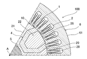
- FIG. 1 is a cross-sectional view of the motor.
- FIG. 2 is an enlarged sectional view of the motor.
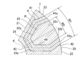
- FIG. 3 is an enlarged sectional view of the rotor.
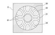
- FIG. 4 is a sectional view showing a state in which the rotor core is set in the mold.
- FIG. 5 is a cross-sectional view showing a state in which a mold is filled with a permanent magnet material.
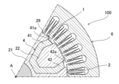
- FIG. 6 is an enlarged cross-sectional view of a modified motor.
- FIG. 7 is an enlarged sectional view of another modified motor.
- FIG. 1 shows a motor 100 according to an embodiment.
- the motor 100 includes a rotor 1 that rotates around a predetermined rotation axis A, and a stator 6 that rotates the rotor 1 around the rotation axis A.
- a permanent magnet 4 is embedded in the rotor 1 . That is, the motor 100 is an IPM (Interior Permanent Magnet) motor.
- the motor 100 may further include a motor case 7 .
- a motor case 7 accommodates the rotor 1 and the stator 6 .
- the stator 6 is fixed with respect to the motor case 7 .
- the rotor 1 is rotatably supported by the motor case 7 .
- rotational axis direction A circumferential direction about the rotation axis A is called a “circumferential direction”.
- a radial direction about the rotation axis A is called a “radial direction”.
- the side facing the rotation axis A in the radial direction is referred to as “radial inner side”, and the side opposite to the rotation axis A is referred to as "radial outer side”.
- the stator 6 has a stator core 61 and windings 62 .
- Stator core 61 is a soft magnetic material.
- the stator core 61 is formed, for example, from a plurality of laminated electromagnetic steel sheets.
- the stator core 61 is formed in an annular shape. Specifically, stator core 61 is formed in a cylindrical shape. The stator core 61 is fixed to the motor case 7 . The stator core 61 is formed with a plurality of teeth 61a projecting inwardly of the stator core 61 . A plurality of teeth 61a are arranged in a line in the circumferential direction of stator core 61 at intervals. The winding 62 is wound around a plurality of teeth 61a. The stator 6 forms a rotating magnetic field that rotates the rotor 1 when current is supplied to the windings 62 .
- the rotor 1 includes a rotor body 2 that rotates around a rotation axis A, and a plurality of permanent magnets 4 that are arranged in the rotor body 2 in the circumferential direction and form magnetic poles that are alternately different in the circumferential direction.
- At least part of the rotor body 2 is made of a soft magnetic material.
- the rotor body 2 has magnetic saliency and generates reluctance torque in the rotating magnetic field created by the stator 6 .
- the rotor body 2 includes a rotor core 20 and a shaft 5 .
- the rotor core 20 is a soft magnetic material.
- the rotor core 20 is formed, for example, from a plurality of electromagnetic steel sheets laminated together.
- the rotor core 20 is formed in an annular shape surrounding the rotation axis A. As shown in FIG. Specifically, rotor core 20 is formed in a cylindrical shape concentric with stator core 61 .
- the outer peripheral surface of the rotor core 20 forms the outer peripheral surface 28 of the rotor body 2 .
- the cross-sectional shape of rotor core 20 orthogonal to rotation axis A is the same over the entire length of rotor core 20 in the rotation axis direction.
- An air gap 10 is formed between the outer peripheral surface of rotor core 20 and the inner peripheral surface of stator core 61 .
- the shaft 5 is fitted inside the rotor core 20 .
- Shaft 5 is fixed to rotor core 20 .
- the axis of the shaft 5 coincides with the rotation axis A.
- the shaft 5 is rotatably supported by the motor case 7 via bearings and the like.
- the rotor core 20 rotates around the rotation axis A together with the shaft 5 .
- the shaft 5 is a soft magnetic material.
- a plurality of permanent magnets 4 are provided on the rotor core 20 .
- a plurality of permanent magnets 4 generate magnet torque in the rotating magnetic field formed by the stator 6 .
- the rotor 1 has six permanent magnets 4 .
- the plurality of permanent magnets 4 are arranged at regular intervals in the circumferential direction.
- the permanent magnet 4 is a bond magnet.
- a bonded magnet is a permanent magnet made of a magnetic material that includes magnet powder and a binder that binds the magnet powder.
- the magnetic powder is, for example, a powder of a neodymium magnet, a samarium-iron-nitrogen magnet, a samarium-cobalt magnet, a ferrite magnet, an alnico magnet, or a mixture of two or more of these powders.
- the binder is, for example, thermosetting resin such as epoxy resin, thermoplastic resin such as polyamide resin, or rubber.
- the permanent magnet 4 is formed by insert molding, for example.
- the permanent magnet 4 is formed by injecting a magnet material that will become a bond magnet into a molding die 8 (see FIGS. 4 and 5) in which the rotor core 20 is housed. That is, the permanent magnet 4 is a hardened magnet material filled inside the rotor core 20 .
- FIG. 2 is an enlarged sectional view of the motor 100.
- FIG. FIG. 3 is an enlarged sectional view of the rotor 1.
- FIG. The permanent magnet 4 is formed in a plate shape extending along the rotation axis A. As shown in FIG. The permanent magnets 4 are formed over the entire length of the rotor core 20 in the rotation axis direction.
- Cross-sectional shape perpendicular to the rotation axis A of the rotor 1 will be described below.
- Cross-sectional shape means a cross-sectional shape orthogonal to the rotation axis A unless otherwise specified.
- the shape of the cross section of the permanent magnet 4 orthogonal to the rotation axis A is the same over the entire length of the permanent magnet 4 in the rotation axis direction.
- the cross-sectional shape of the permanent magnet 4 is linear. That is, the cross-sectional shape of the permanent magnet 4 has a shape extending along the predetermined reference line R. As shown in FIG.
- the permanent magnet 4 has two ends 41 and 42 and an intermediate portion 43 positioned between the two ends 41 and 42 in the direction in which the reference line R extends. Note that the intermediate portion 43 does not refer to the entire remaining portion of the permanent magnet 4 excluding the two ends 41 and 42, but at least a portion of the remaining portion excluding the two ends 41 and 42. Point.
- the intermediate portion 43 may or may not include the center of the permanent magnet 4 in the direction in which the reference line R extends.
- the cross-sectional shape of the permanent magnet 4 is curved or bent so as to be concave radially inward. That is, the permanent magnet 4 is curved or bent such that the two ends 41 and 42 are closer to the outer peripheral surface 28 of the rotor body 2 (that is, the outer peripheral surface of the rotor core 20) than the intermediate portion 43 is. Specifically, the cross-sectional shape of the permanent magnet 4 is formed in a U-shape recessed radially inward. More specifically, the cross-sectional shape of the permanent magnet 4 is linearly symmetrical about a symmetrical axis extending in the radial direction.
- the dimension of the permanent magnet 4 in the direction parallel to the plane orthogonal to the rotation axis A and orthogonal to the reference line R (hereinafter this dimension is also referred to as thickness) is substantially constant. At least one of the two ends 41 and 42 of the permanent magnet 4 is exposed from the outer peripheral surface 28 of the rotor body 2 . In this example, both ends 41 and 42 of permanent magnet 4 are exposed from outer peripheral surface 28 of rotor body 2 . The radially outer surfaces of the two ends 41 and 42 of the permanent magnet 4 are flush with the outer peripheral surface 28 of the rotor body 2 .
- the permanent magnet 4 is magnetized in a direction crossing the reference line R in a cross section orthogonal to the rotation axis A. Specifically, the magnetization direction of the permanent magnet 4 is orthogonal to the reference line R.
- the axis of symmetry which is the center of the linearly symmetrical shape of the permanent magnets 4, is set to the d-axis of the rotor 1, for example.
- the rotor body 2 includes a first portion 21 and a second portion 22 separated by a plurality of permanent magnets 4 .
- the rotor body 2 includes the same number of second parts 22 as the permanent magnets 4 .
- the first portion 21 is a portion of the rotor body 2 that includes or encloses the rotation axis A.
- the first portion 21 also includes the shaft 5 .
- the outer peripheral surface of the first portion 21 is formed by a plurality of curved surfaces 23 coinciding with the outer peripheral surface of a single imaginary cylinder centered on the rotation axis A, and a plurality of recesses 24 recessed radially inward.
- the curved surfaces 23 and the recesses 24 are alternately arranged in the circumferential direction. That is, one curved surface 23 is arranged between each two adjacent recesses 24 . In other words, one recess 24 is arranged between each two adjacent curved surfaces 23 .
- the plurality of curved surfaces 23 are arranged at regular intervals in the circumferential direction.
- a plurality of curved surfaces 23 are arranged on the outer peripheral surface of a single imaginary cylinder having the rotation axis A as its axis.
- the number of curved surfaces 23 is the same as the number of permanent magnets 4 .
- the plurality of recesses 24 are arranged at regular intervals in the circumferential direction. Each recess 24 extends in the rotation axis direction and opens radially outward. The number of recesses 24 is the same as the number of permanent magnets 4 .
- the permanent magnet 4 is housed in the recess 24 .
- the cross-sectional shape of the permanent magnet 4 is, as described above, curved or bent so as to be concaved radially inward. That is, the permanent magnet 4 has a shape that fits in the concave portion 24 .
- the permanent magnet 4 is in close contact with the inner surface 24 a of the recess 24 .
- the permanent magnet 4 extends in the rotation axis direction and has a recess 44 that opens radially outward.
- the recess 44 accommodates the second portion 22 .
- the second portion 22 is located radially outside the intermediate portion 43 of the permanent magnet 4 .
- the second portion 22 is shaped to fit in the recess 44 .
- the second portion 22 has an inner surface 22 a positioned within the recess 44 and an outer surface 22 b exposed radially outward from the recess 44 .
- the inner surface 22 a is in close contact with the permanent magnet 4 .
- the outer surface 22b forms, together with the curved surface 23 of the first portion 21, the outer peripheral surface of a single virtual cylinder having the rotation axis A as its axis.
- An outer peripheral surface 28 of the rotor body 2 is formed by the curved surface 23 and the outer surface 22b.
- a permanent magnet 4 is interposed between the first portion 21 and the second portion 22 .
- the second portion 22 is separated from the first portion 21 and is not connected to the first portion 21 .
- the inner surface 24a of the concave portion 24 of the first portion 21 and the permanent magnet 4 are adhered.
- the inner surface 22a of the second portion 22 and the permanent magnet 4 are adhered.
- the first part 21, the second part 22 and the permanent magnet 4 are integrally fixed by these.
- the ends 41 and 42 of the permanent magnet 4 are exposed radially outward from between the first portion 21 and the second portion 22 .
- the end portion 41 has an end surface 41a located at one end in the direction of the reference line R.
- the end portion 42 has an end face 42a positioned at the other end in the direction of the reference line R.
- the end surface 41a and the end surface 42a are smoothly connected to the curved surface 23 of the first portion 21 and the outer surface 22b of the second portion 22 to form a single curved surface.
- the curved surface 23, the outer surface 22b, the end surface 41a, and the end surface 42a form the outer peripheral surface of a single virtual cylinder with the rotation axis A as the axis.
- each of the two ends 41 and 42 of the permanent magnet 4 is linear.
- the two ends 41 and 42 are each inclined with respect to the radial direction.
- the circumferential width W1 of the two ends 41 and 42 increases as it approaches the outer peripheral surface 28 of the rotor body 2 (that is, the rotational width). The distance from the axis A) is smaller.
- the circumferential distance between the recesses 24 (that is, the inner surface 24 a ) also decreases as it approaches the outer peripheral surface 28 of the rotor body 2 .
- the circumferential interval of the concave portion 44 of the permanent magnet 4 that is, the inner interval of the two end portions 41 and 42 in the circumferential direction is also the outer peripheral surface 28 of the rotor body 2. becomes smaller as it approaches .
- the circumferential width of the portion 22c sandwiched between the two ends 41 and 42 of the second portion 22 also increases as it approaches the outer peripheral surface 28 of the rotor body 2. It's getting smaller.
- FIG. 4 is a cross-sectional view showing a state in which the rotor core 20 is set in the mold 8.
- FIG. 5 is a cross-sectional view showing a state in which the mold 8 is filled with a magnet material that will become the permanent magnet 4.
- the permanent magnet 4 is molded using a molding die 8 as shown in FIGS. 4 and 5, for example.
- the second portion 22 and the first portion 21 of the rotor core 20 are set in the molding die 8 .
- the second portion 22 is arranged in the concave portion 24 of the first portion 21 with the cavity 81 for molding the permanent magnet 4 formed between the second portion 22 and the first portion 21 .
- a magnet material that will form the permanent magnets 4 is injected into the cavity 81 in the molding die 8 , thereby integrally molding the permanent magnets 4 with the rotor core 20 .
- the ends 41 and 42 of the permanent magnets 4 are exposed from the outer peripheral surface 28 of the rotor body 2, so that the magnetic flux generated by the permanent magnets 4 does not interlink with the windings 62 of the stator 6. Leakage magnetic flux (magnetic flux short circuit) returning to the permanent magnet 4 is less likely to occur. Specifically, from the viewpoint of magnet torque, more magnetic flux goes out from the permanent magnet 4 to the outside of the outer peripheral surface 28 of the rotor body 2, and more magnetic flux enters the permanent magnet 4 from the outside of the outer peripheral surface 28.
- the ends 41 and 42 of the permanent magnet 4 magnetized in the direction crossing the reference line R are completely surrounded by the rotor body 2, part of the magnetic flux generated by the permanent magnet 4 is 2 can be wrapped around the outer portions of the ends 41 and 42 and immediately returned to the permanent magnet 4 .
- the magnetic flux that contributes to the magnet torque is reduced.
- the ends 41 and 42 of the permanent magnet 4 are exposed from the outer peripheral surface 28 of the rotor body 2 .
- the rotor body 2 having a higher magnetic permeability than the permanent magnets 4 does not exist radially outside the exposed ends 41 and 42 .
- the rotor main body 2 will move toward the first portion 21 by the permanent magnet 4 . and a second portion 22 . Therefore, there is a risk that the second portion 22 that receives the centrifugal force during rotation of the rotor 1 will come off and separate from the permanent magnet 4 . Further, if the permanent magnets 4 are subjected to centrifugal force during rotation of the rotor 1, there is a risk that the permanent magnets 4 will come off the first portion 21 and be separated.
- the width W2 in the circumferential direction of the portion 22c sandwiched between the two ends 41 and 42 of the permanent magnet 4 in the second portion 22 of the rotor body 2 becomes smaller as it approaches the outer peripheral surface 28 of the rotor body 2. .
- the second portion 22 receives centrifugal force during rotation of the rotor 1 , the second portion 22 is supported from the radially outer side by the two ends 41 and 42 of the permanent magnet 4 . Therefore, the second portion 22 becomes difficult to come off from the permanent magnet 4 .
- Fig. 6 shows an enlarged sectional view of a modified motor.
- at least one of the two ends 41 and 42 of the permanent magnet 4 may be located radially inside the outer peripheral surface 28 of the rotor body 2 .
- both of the two ends 41 and 42 of the permanent magnet 4 (specifically, both of the end surfaces 41a and 42a) are located radially inward of the outer peripheral surface 28 of the rotor body 2 .
- the distance from the ends 41 and 42 of the permanent magnet 4 to the stator 6 can be lengthened. Therefore, demagnetization of the permanent magnet 4 by the stator 6 can be made difficult to occur.
- the end surfaces 41a and 42a of the two ends 41 and 42 of the permanent magnet 4 are flush with the outer peripheral surface 28 of the rotor body 2, air resistance during rotation of the rotor 1 is reduced. It is advantageous in that it can be used.
- the rotor 1 includes a rotor body 2 that rotates about the rotation axis A, and a plurality of magnetic poles that are arranged in the rotor body 2 in the circumferential direction about the rotation axis A and form different magnetic poles alternately in the circumferential direction.
- the permanent magnet 4 has a cross-sectional shape that extends along a predetermined reference line R, and the permanent magnet 4 is perpendicular to the rotation axis A. At least one end 41 (or 42 ) of the permanent magnet 4 in the direction of the reference line R is exposed from the outer peripheral surface 28 of the rotor body 2 .
- the motor 100 also includes a rotor 1 and a stator 6 that drives the rotor 1 .
- the magnetic flux generated by the permanent magnet 4 is less likely to leak through the radially outer sides of the ends 41 and 42 . Therefore, magnet torque generated by the magnetic flux of the permanent magnet 4 can be improved.
- the permanent magnet 4 is curved or bent so that the two ends 41 and 42 in the direction of the reference line R are closer to the outer peripheral surface 28 of the rotor body 2 than the intermediate portion 43 is. Both of the portions 41 and 42 are exposed from the outer peripheral surface 28 of the rotor body 2 . Two ends 41 and 42 of the permanent magnet 4 are each exposed outside the rotor body 2 .
- the cross-sectional shape of the permanent magnet 4 is curved or bent so that the two end portions 41 and 42 are closer to the outer peripheral surface 28 of the rotor body 2 than the intermediate portion 43 is. , both of the two ends 41 and 42 of the permanent magnet 4 can be exposed from the outer peripheral surface 28 of the rotor body 2, and as a result, leakage magnetic flux of the permanent magnet 4 can be made more difficult to occur.
- the width W1 in the circumferential direction from one end 41 to the other end 42 of the two ends 41 and 42 of the permanent magnet 4 becomes smaller as it approaches the outer peripheral surface 28 of the rotor body 2 .
- the permanent magnets 4 when the permanent magnets 4 receive centrifugal force during rotation of the rotor 1, the permanent magnets 4 can be supported by the rotor main body 2 from the radially outer side. It can be made difficult to come off from the main body 2. - ⁇
- the width W2 in the circumferential direction of the portion 22c sandwiched between the two ends 41 and 42 of the permanent magnet 4 of the rotor body 2 becomes smaller as the rotor body 2 approaches the outer peripheral surface 28 thereof.
- the portion 22c when the portion 22c receives centrifugal force during rotation of the rotor 1, the portion 22c can be supported from the radially outer side by the two ends 41 and 42 of the permanent magnet 4. , the portion 22c becomes difficult to come off from the permanent magnet 4.
- At least one of the two ends 41 and 42 of the permanent magnet 4 is located radially inward of the outer peripheral surface 28 of the rotor body 2 around the rotation axis A.
- the distance from the ends 41 and 42 of the permanent magnet 4 to the stator 6 can be increased. Therefore, demagnetization of the permanent magnet 4 by the stator 6 can be made difficult to occur.
- the permanent magnet 4 is a bond magnet.
- the rotor body 2 may be formed only by the rotor core 20 without the shaft 5.
- the rotor body 2 may be formed only by the shaft 5 without the rotor core 20 .
- the shaft 5 does not have to be a soft magnetic material.
- Shaft 5 may be formed integrally with rotor core 20 .
- the first part 21 and the second part 22 of the rotor body 2 are not limited to being separated, and as shown in FIG. It may have a portion 27 . In this case, the second portion 22 is connected to the first portion 21 via the connecting portion 27 so that the second portion 22 does not come off the permanent magnet 4 when the rotor 1 rotates.
- the permanent magnet 4 since the permanent magnet 4 is held by the first portion 21 and the second portion 22 that are connected to each other, the permanent magnet 4 also does not come off from the first portion 21 . Therefore, when the first portion 21 and the second portion 22 are connected by the connecting portion 27 in this way, the width W1 of the two ends 41 and 42 of the permanent magnet 4 is equal to the outer peripheral surface of the rotor body 2.
- the width W2 of the portion 22c of the rotor body 2 sandwiched between the two ends 41 and 42 of the permanent magnet 4 in the circumferential direction increases as the rotor body 2 approaches the outer peripheral surface. It doesn't have to be small.
- the number of permanent magnets 4 that the rotor 1 has is not limited.
- the permanent magnet 4 may be an anisotropic bonded magnet or an isotropic bonded magnet.
- the permanent magnet 4 may be a sintered magnet formed by sintering magnetic powder.
- the cross-sectional shape of the permanent magnet 4 is not limited.
- the cross-sectional shape of the permanent magnet 4 may be, for example, V-shaped or W-shaped. Only one of the two ends 41 and 42 of the permanent magnet 4 may be exposed from the outer peripheral surface 28 of the rotor body 2 .
- the permanent magnet 4 may be flat (that is, have a linear cross-sectional shape), and only one end of the cross-sectional shape may be exposed from the outer peripheral surface 28 of the rotor body 2 .
- the width W1 of the two ends 41 and 42 of the permanent magnet 4 does not need to become smaller as it approaches the outer peripheral surface of the rotor body 2.
- the width W2 in the circumferential direction of the portion 22c sandwiched between the two ends 41 and 42 of the permanent magnet 4 in the rotor body 2 does not need to decrease as the rotor body 2 approaches the outer peripheral surface.
Landscapes
- Engineering & Computer Science (AREA)
- Power Engineering (AREA)
- Permanent Field Magnets Of Synchronous Machinery (AREA)
Abstract
Description
以上のように、本出願において開示する技術の例示として、前記実施形態を説明した。しかしながら、本開示における技術は、これに限定されず、適宜、変更、置き換え、付加、省略などを行った実施の形態にも適用可能である。また、前記実施形態で説明した各構成要素を組み合わせて、新たな実施の形態とすることも可能である。また、添付図面および詳細な説明に記載された構成要素の中には、課題解決のために必須な構成要素だけでなく、前記技術を例示するために、課題解決のためには必須でない構成要素も含まれ得る。そのため、それらの必須ではない構成要素が添付図面や詳細な説明に記載されていることをもって、直ちに、それらの必須ではない構成要素が必須であるとの認定をするべきではない。
1 ロータ
2 ロータ本体
22c 部分
28 外周面
4 永久磁石
41 端部
42 端部
43 中間部
6 ステータ
R 基準線
A 回転軸
W1 幅
W2 幅
Claims (7)
- 回転軸回りに回転するロータ本体と、
前記ロータ本体において前記回転軸を中心とする周方向に配列され、前記周方向において交互に異なる磁極を形成する複数の永久磁石とを備え、
前記回転軸に直交する、前記永久磁石の断面形状は、所定の基準線に沿って延びる形状をしており、
前記永久磁石は、前記回転軸に直交する断面において前記基準線と交差する方向に磁化され、
前記永久磁石のうち前記基準線の方向における少なくとも一方の端部は、前記ロータ本体の外周面から露出しているロータ。 - 請求項1に記載のロータにおいて、
前記永久磁石は、前記基準線の方向における2つの端部の方が中間部よりも前記ロータ本体の前記外周面に接近するように湾曲又は屈曲しており、
前記2つの端部の両方は、前記ロータ本体の外周面から露出しているロータ。 - 請求項2に記載のロータにおいて、
前記永久磁石の前記2つの端部のうちの一方の端部から他方の端部までの、前記周方向における幅は、前記ロータ本体の前記外周面に近づくにつれて小さくなるロータ。 - 請求項2又は3の何れか1つに記載のロータにおいて、
前記ロータ本体のうち前記永久磁石の前記2つの端部に挟まれた部分の、前記周方向における幅は、前記ロータ本体の前記外周面に近づくにつれて小さくなるロータ。 - 請求項1乃至4の何れか1つにおいて、
前記永久磁石の前記2つの端部のうち少なくとも一方は、前記ロータ本体の前記外周面よりも前記回転軸を中心とする径方向内側に位置するロータ。 - 請求項1乃至5の何れか1つに記載のロータにおいて、
前記永久磁石は、ボンド磁石であるロータ。 - 請求項1乃至6の何れか1つに記載のロータと、
前記ロータを駆動するステータとを備えたモータ。
Priority Applications (4)
| Application Number | Priority Date | Filing Date | Title |
|---|---|---|---|
| JP2023538170A JP7679475B2 (ja) | 2021-07-30 | 2021-07-30 | ロータ及びモータ |
| PCT/JP2021/028380 WO2023007708A1 (ja) | 2021-07-30 | 2021-07-30 | ロータ及びモータ |
| CN202180100640.8A CN117730468A (zh) | 2021-07-30 | 2021-07-30 | 转子以及马达 |
| US18/291,923 US12646983B2 (en) | 2021-07-30 | 2021-07-30 | Rotor and motor |
Applications Claiming Priority (1)
| Application Number | Priority Date | Filing Date | Title |
|---|---|---|---|
| PCT/JP2021/028380 WO2023007708A1 (ja) | 2021-07-30 | 2021-07-30 | ロータ及びモータ |
Publications (1)
| Publication Number | Publication Date |
|---|---|
| WO2023007708A1 true WO2023007708A1 (ja) | 2023-02-02 |
Family
ID=85086458
Family Applications (1)
| Application Number | Title | Priority Date | Filing Date |
|---|---|---|---|
| PCT/JP2021/028380 Ceased WO2023007708A1 (ja) | 2021-07-30 | 2021-07-30 | ロータ及びモータ |
Country Status (4)
| Country | Link |
|---|---|
| US (1) | US12646983B2 (ja) |
| JP (1) | JP7679475B2 (ja) |
| CN (1) | CN117730468A (ja) |
| WO (1) | WO2023007708A1 (ja) |
Citations (4)
| Publication number | Priority date | Publication date | Assignee | Title |
|---|---|---|---|---|
| JPS5359810A (en) * | 1976-10-05 | 1978-05-30 | Bogue Elec Mfg Co | Ac synchronous magnetic reluctance motor |
| JP2012178922A (ja) * | 2011-02-25 | 2012-09-13 | Railway Technical Research Institute | 永久磁石同期機 |
| JP2015082860A (ja) * | 2013-10-21 | 2015-04-27 | 株式会社安川電機 | 回転電機及び回転子鉄心の製造方法 |
| JP2016096665A (ja) * | 2014-11-14 | 2016-05-26 | 株式会社ジェイテクト | 回転電機用ロータおよびその製造方法 |
Family Cites Families (11)
| Publication number | Priority date | Publication date | Assignee | Title |
|---|---|---|---|---|
| JP4248778B2 (ja) * | 2001-10-25 | 2009-04-02 | アイチエレック株式会社 | 永久磁石形電動機の回転子 |
| US7981359B2 (en) * | 2004-04-06 | 2011-07-19 | Hitachi Metals, Ltd. | Rotor and process for manufacturing the same |
| DE102009000028A1 (de) | 2009-01-05 | 2010-07-08 | Robert Bosch Gmbh | Gleichstrommotor |
| JP6007593B2 (ja) * | 2012-05-25 | 2016-10-12 | 株式会社ジェイテクト | ロータ及びこれを備えた回転電機、及びロータの製造方法 |
| WO2016002002A1 (ja) * | 2014-07-01 | 2016-01-07 | 三菱電機株式会社 | 永久磁石埋込型電動機、圧縮機及び冷凍空調装置 |
| JP2017118796A (ja) | 2015-12-25 | 2017-06-29 | 株式会社ジェイテクト | 埋込磁石型ロータユニット |
| US10516307B2 (en) * | 2016-08-30 | 2019-12-24 | Hamilton Sundstrand Corporation | Interior permanent magnet motor/rotor with curved and spoke-type permanent magnets |
| CN206135581U (zh) * | 2016-09-22 | 2017-04-26 | 珠海格力节能环保制冷技术研究中心有限公司 | 电机转子以及永磁电机 |
| CN108023421B (zh) * | 2017-12-21 | 2024-05-28 | 珠海格力电器股份有限公司 | 电机转子和永磁电机 |
| JP7103284B2 (ja) | 2019-03-22 | 2022-07-20 | 株式会社デンソー | 回転電機の回転子及びその製造方法 |
| JP7293859B2 (ja) | 2019-05-20 | 2023-06-20 | 株式会社ジェイテクト | 埋込磁石型ロータおよび埋込磁石型ロータの製造方法 |
-
2021
- 2021-07-30 WO PCT/JP2021/028380 patent/WO2023007708A1/ja not_active Ceased
- 2021-07-30 CN CN202180100640.8A patent/CN117730468A/zh active Pending
- 2021-07-30 US US18/291,923 patent/US12646983B2/en active Active
- 2021-07-30 JP JP2023538170A patent/JP7679475B2/ja active Active
Patent Citations (4)
| Publication number | Priority date | Publication date | Assignee | Title |
|---|---|---|---|---|
| JPS5359810A (en) * | 1976-10-05 | 1978-05-30 | Bogue Elec Mfg Co | Ac synchronous magnetic reluctance motor |
| JP2012178922A (ja) * | 2011-02-25 | 2012-09-13 | Railway Technical Research Institute | 永久磁石同期機 |
| JP2015082860A (ja) * | 2013-10-21 | 2015-04-27 | 株式会社安川電機 | 回転電機及び回転子鉄心の製造方法 |
| JP2016096665A (ja) * | 2014-11-14 | 2016-05-26 | 株式会社ジェイテクト | 回転電機用ロータおよびその製造方法 |
Also Published As
| Publication number | Publication date |
|---|---|
| US12646983B2 (en) | 2026-06-02 |
| CN117730468A (zh) | 2024-03-19 |
| JP7679475B2 (ja) | 2025-05-19 |
| JPWO2023007708A1 (ja) | 2023-02-02 |
| US20250030286A1 (en) | 2025-01-23 |
Similar Documents
| Publication | Publication Date | Title |
|---|---|---|
| JP5398512B2 (ja) | アキシャルギャップ型永久磁石モータ、それに用いるロータ、及びそのロータの製造方法 | |
| JP2002010547A (ja) | 永久磁石回転子及びその製造方法 | |
| US10566859B2 (en) | Rotor | |
| US20160285327A1 (en) | Motor | |
| JP7706001B2 (ja) | ロータ及びモータ | |
| KR102349405B1 (ko) | 본드 자석을 이용한 회전자 및 그를 포함하는 모터 | |
| JP2013236418A (ja) | 回転電気機械 | |
| JP2014007928A (ja) | 界磁子および回転電機 | |
| US12519356B2 (en) | Rotor and rotating electric machine | |
| JP7723102B2 (ja) | インナロータ及びモータ | |
| CN115208095A (zh) | 马达 | |
| JP2002034188A (ja) | 永久磁石電動機およびその製造方法 | |
| JP7654795B2 (ja) | ロータおよびモータ | |
| JP2014233100A (ja) | 永久磁石式回転電機 | |
| JP7679475B2 (ja) | ロータ及びモータ | |
| WO2007010948A1 (ja) | ブラシレスモータおよびそのロータ | |
| WO2022219896A1 (ja) | 回転電機のロータ、回転電機及び電動駆動システム | |
| JP7654090B2 (ja) | ロータ、モータ、及びロータの製造方法 | |
| JP7774454B2 (ja) | 永久磁石型回転機 | |
| JP7401737B2 (ja) | 回転子、モータ | |
| CN104067483B (zh) | 同步电动机 | |
| JP2022157628A (ja) | 高速モータ用ロータ及びその製造方法 | |
| JP2002159150A (ja) | 回転機 | |
| JP4714512B2 (ja) | モータの回転子及び回転子の製造方法 | |
| WO2024142392A1 (ja) | ロータ及びロータの製造方法 |
Legal Events
| Date | Code | Title | Description |
|---|---|---|---|
| 121 | Ep: the epo has been informed by wipo that ep was designated in this application |
Ref document number: 21951907 Country of ref document: EP Kind code of ref document: A1 |
|
| WWE | Wipo information: entry into national phase |
Ref document number: 2023538170 Country of ref document: JP |
|
| WWE | Wipo information: entry into national phase |
Ref document number: 202180100640.8 Country of ref document: CN |
|
| WWE | Wipo information: entry into national phase |
Ref document number: 18291923 Country of ref document: US |
|
| NENP | Non-entry into the national phase |
Ref country code: DE |
|
| 122 | Ep: pct application non-entry in european phase |
Ref document number: 21951907 Country of ref document: EP Kind code of ref document: A1 |
|
| WWG | Wipo information: grant in national office |
Ref document number: 18291923 Country of ref document: US |