WO2023007644A1 - 固定子、回転電機、圧縮機、及び冷凍サイクル装置 - Google Patents
固定子、回転電機、圧縮機、及び冷凍サイクル装置 Download PDFInfo
- Publication number
- WO2023007644A1 WO2023007644A1 PCT/JP2021/028053 JP2021028053W WO2023007644A1 WO 2023007644 A1 WO2023007644 A1 WO 2023007644A1 JP 2021028053 W JP2021028053 W JP 2021028053W WO 2023007644 A1 WO2023007644 A1 WO 2023007644A1
- Authority
- WO
- WIPO (PCT)
- Prior art keywords
- stator
- core
- insulating film
- length
- stator cores
- Prior art date
- Legal status (The legal status is an assumption and is not a legal conclusion. Google has not performed a legal analysis and makes no representation as to the accuracy of the status listed.)
- Ceased
Links
Images










Classifications
-
- H—ELECTRICITY
- H02—GENERATION; CONVERSION OR DISTRIBUTION OF ELECTRIC POWER
- H02K—DYNAMO-ELECTRIC MACHINES
- H02K3/00—Details of windings
- H02K3/32—Windings characterised by the shape, form or construction of the insulation
- H02K3/34—Windings characterised by the shape, form or construction of the insulation between conductors or between conductor and core, e.g. slot insulation
-
- Y—GENERAL TAGGING OF NEW TECHNOLOGICAL DEVELOPMENTS; GENERAL TAGGING OF CROSS-SECTIONAL TECHNOLOGIES SPANNING OVER SEVERAL SECTIONS OF THE IPC; TECHNICAL SUBJECTS COVERED BY FORMER USPC CROSS-REFERENCE ART COLLECTIONS [XRACs] AND DIGESTS
- Y02—TECHNOLOGIES OR APPLICATIONS FOR MITIGATION OR ADAPTATION AGAINST CLIMATE CHANGE
- Y02T—CLIMATE CHANGE MITIGATION TECHNOLOGIES RELATED TO TRANSPORTATION
- Y02T10/00—Road transport of goods or passengers
- Y02T10/60—Other road transportation technologies with climate change mitigation effect
- Y02T10/64—Electric machine technologies in electromobility
Definitions
- the present disclosure relates to stators, rotating electric machines, compressors, and refrigeration cycle devices, and particularly to insulating films.
- a film insulation method using a thin and inexpensive film as an insulating member is known. Reducing the thickness of the insulating member makes it possible to increase the space for arranging the windings in the slots of the stator core.
- a thick wire can be used.
- a stator with thin insulating members can use thicker wires for windings than a stator without thin insulating members, which reduces winding resistance and reduces copper loss. Improvements can be made.
- the film that covers the adjacent split cores is longer than the distance between the teeth of the split cores during winding, and the extra length of the film floats in the winding track. It is conceivable that the winder nozzle would entrain the film. Therefore, in the stator of Patent Document 1, it is necessary to strictly measure the dimensions of the insulating film so as not to generate excess length of the insulating film. However, if the film size is determined so as not to generate excess length of the insulating film, the insulating film will get caught in the connecting part of the split core when closing the split core in an annular shape after winding, resulting in deterioration of the stator shape, Alternatively, it may cause insulation failure.
- the present disclosure is intended to solve the above-described problems, and provides a stator, a rotating electric machine, a compressor, and a refrigeration cycle device that can suppress entrainment of the insulating film and entrapment of the insulating film after winding. is.
- a stator according to the present disclosure is a stator used in a rotating electrical machine, and includes a plurality of split stator cores connected to each other and arranged in an annular shape, and an insulating member, each of the plurality of split stator cores.
- a pair of insulators arranged on both axial end faces of the split stator cores of the plurality of split stator cores are mounted on surfaces forming slots that are spaces between adjacent split stator cores, and a plurality of and an insulating film for insulating the plurality of split stator cores, each of the plurality of split stator cores extending in the circumferential direction of the stator a core-back portion and tooth portions protruding from the central portion of the core-back portion toward the center of the stator and around which windings are wound; the insulating film is in contact with the core-back portion; of the split stator cores adjacent to each other, and each end is provided with a concavo-convex portion whose concavo-convex shape matches that of the ends, and the end portion of the insulating film having the concavo-convex portion is adjacent to the other It is arranged to overlap with the insulating film of
- a rotating electric machine includes a stator configured as described above and a rotor provided inside the stator and rotating by magnetic action.
- a compressor according to the present disclosure includes a rotating electric machine configured as described above, a compression mechanism section that is driven by the rotating electric machine and compresses a fluid sucked from the outside, and an airtight container that houses the rotating electric machine and the compression mechanism section. is.
- a refrigeration cycle device includes a compressor configured as described above, an outdoor heat exchanger that exchanges heat between outdoor air and a refrigerant flowing inside, a pressure reducing device that reduces the pressure of the refrigerant flowing inside, an indoor It is provided with an indoor heat exchanger that exchanges heat between the air and the refrigerant flowing inside.
- the insulating film is in contact with the core-back portion, and is arranged on adjacent split stator cores among the plurality of split stator cores. Each end is provided with a concavo-convex portion in which the concavo-convex shape of the ends is the same.
- the edge of the insulating film having the uneven portion overlaps with the adjacent insulating film. Since the insulating films are arranged in the above state, the insulating films overlap the gaps between the adjacent split stator cores. Therefore, in the stator, when the split stator cores are bent into an annular shape, it is possible to prevent the insulation film from being caught in the gap between the adjacent split stator cores and the insulation film from being caught after the winding.
- FIG. 1 is a longitudinal sectional view of a compressor according to Embodiment 1;
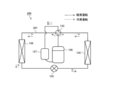
- FIG. 1 is a schematic configuration diagram of a refrigeration cycle apparatus such as an air conditioner to which a compressor according to Embodiment 1 is connected;
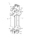
- FIG. FIG. 2 is a perspective view showing part of a stator used in the rotary electric machine of the compressor according to Embodiment 1;
- FIG. 2 is a plan view showing part of a stator used in the rotary electric machine of the compressor according to Embodiment 1;
- FIG. 2 is a conceptual diagram illustrating fixing claws of an insulator of a stator used in the rotary electric machine of the compressor according to Embodiment 1;
- FIG. 6 is a partially enlarged view of part A of FIG. 5;
- FIG. 5 is a partially enlarged view of part A of FIG. 5;
- FIG. 4 is a conceptual diagram illustrating fixing of an insulating film by fixing claws of the compressor according to Embodiment 1;
- FIG. 2 is a plan view when a plurality of split stator cores forming the stator of Embodiment 1 are arranged in a straight line;
- FIG. 9 is a plan view of a stator in which insulators and windings are attached to a plurality of split stator cores shown in FIG. 8;
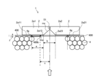
- FIG. 10 is a plan view conceptually showing a connecting portion of the stator shown in FIG. 9;
- FIG. 11 is a side view of the stator of Embodiment 1 as viewed in the direction of the white arrow in FIG. 10;
- FIG. 2 is a side view conceptually showing an insulating film used in the stator according to Embodiment 1;
- FIG. 4 is a side view conceptually showing another example of an insulating film used in the stator according to Embodiment 1;
- FIG. 4 is a conceptual diagram illustrating a fractured surface after cutting of an insulating film used in the stator according to Embodiment 1;
- FIG. 10 is a conceptual diagram illustrating winding of an insulating film in a stator winding process according to a comparative example;
- FIG. 7 is a conceptual diagram illustrating how an insulating film gets caught when the split stator cores of the stator according to the comparative example are annularly closed.
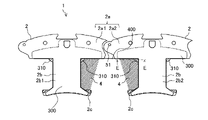
- FIG. 4 is a conceptual diagram showing an overlapping state of insulating films of the stator according to Embodiment 1; 18 is an enlarged view of the slot portion of the stator according to Embodiment 1, and is an enlarged view of the A portion of the stator shown in FIG. 17.
- FIG. 8 is a conceptual diagram illustrating a cuttable portion of an insulating film using a plan view and a side view of an inner diameter side of a stator according to Embodiment 2; FIG.
- FIG. 7 is a conceptual diagram showing an overlapping state of insulating films of a stator according to Embodiment 2;
- 21 is an enlarged view of the slot portion of the stator according to Embodiment 2, and is an enlarged view showing the relationship between the insulating film on one end side and the windings in the A portion shown in FIG. 20.
- FIG. 21 is an enlarged view of the slot portion of the stator according to Embodiment 2, and is an enlarged view showing the relationship between the insulating film on the other end side of the portion A shown in FIG. 20 and the windings.
- FIG. 11 is a conceptual diagram illustrating a cuttable portion of an insulating film using a plan view and a side view of an inner diameter side of a stator according to Embodiment 3;
- FIG. 11 is a side view conceptually showing an insulating film used in a stator according to Embodiment 3;
- FIG. 11 is a plan view showing a state in which insulators and windings are attached to the split stator core of the stator according to Embodiment 3;
- FIG. 26 is an enlarged plan view showing a portion B of the stator shown in FIG. 25;
- FIG. 11 is a conceptual diagram showing insulating films of a stator according to Embodiment 3;
- FIG. 28 is an enlarged view of the slot portion of the stator according to Embodiment 3, and is an enlarged view of the A portion of the stator shown in FIG. 27;
- FIG. 1 is a longitudinal sectional view of compressor 130 according to Embodiment 1.
- FIG. Compressor 130 which is a hermetic compressor, will be described with reference to FIG.
- the compressor 130 sucks a low-temperature, low-pressure refrigerant, compresses the sucked refrigerant, and discharges a high-temperature, high-pressure refrigerant.
- the compressor 130 is a one-cylinder rotary compressor, and is a fluid machine that discharges low-pressure gas refrigerant sucked into the compressor 130 as high-pressure gas refrigerant.
- the one-cylinder rotary compressor is an example of the compressor 130, and the compressor 130 may be a closed compressor such as a scroll compressor or a reciprocating compressor in which the rotating electric machine 103 is arranged in the closed container 101. Any compression structure is acceptable.
- Compressor 130 accommodates compression mechanism 102 for compressing refrigerant and rotary electric machine 103 for driving compression mechanism 102 in sealed container 101 configured by upper container 101a and lower container 101b. .
- the closed container 101 constitutes the outer shell of the compressor 130 .
- the compression mechanism section 102 and the rotary electric machine 103 are connected by a crankshaft 104 , and the compression mechanism section 102 is housed in the lower portion of the sealed container 101 and the rotary electric machine 103 is housed in the upper portion of the sealed container 101 .
- the compression mechanism 102 is driven by the rotating electric machine 103 and compresses the fluid sucked from the outside.
- the compression mechanism unit 102 compresses the low-pressure gas refrigerant sucked into the low-pressure space of the sealed container 101 from the suction coupling pipe 128 into a high-pressure gas refrigerant by the rotational driving force supplied from the rotary electric machine 103, and compresses the compressed high-pressure gas refrigerant.
- Gas refrigerant is discharged above the compression mechanism portion 102 .
- the compression mechanism section 102 has a hollow cylindrical cylinder 105 .
- the compression mechanism portion 102 has a rolling piston 109 which is fitted in the eccentric portion 104c of the crankshaft 104 and accommodated in the cylinder 105. As shown in FIG.
- the compression mechanism 102 forms a compression chamber while one end of a vane (not shown) that reciprocates radially in a groove provided in the cylinder 105 contacts the outer circumference of the rolling piston 109 .
- Openings at both axial ends of the cylinder 105 are closed by an upper bearing 106 and a lower bearing 107 .
- a space surrounded by the rolling piston 109, the cylinder 105, the vanes, the upper bearing 106, and the lower bearing 107 forms a compression chamber for compressing the low-pressure gas refrigerant sucked from the intake connecting pipe 128. .
- a silencer 108 may be provided on the upper surface side of the upper bearing 106 to remove or reduce noise generated when the refrigerant is compressed in the compression mechanism section 102 .
- the muffler 108 is formed with an opening 108 a through which high-pressure gas refrigerant flowing from a discharge port (not shown) provided in the upper bearing 106 is discharged into the sealed container 101 .
- the rotating electric machine 103 is an electric motor arranged inside the sealed container 101 and used to move the compression mechanism section 102 .
- the rotating electrical machine 103 is a motor that uses electric power supplied from an external power source to generate a rotational driving force in the crankshaft 104 and transmits the rotational driving force to the compression mechanism section 102 via the crankshaft 104 .
- a brushless DC motor for example, is used for the rotating electric machine 103 .
- the rotating electric machine 103 includes a stator 1 that has a hollow cylindrical appearance when viewed from above, and a rotor 5 that is rotatably arranged inside the inner surface of the stator 1 and rotates by magnetic action.
- the stator 1 is formed by stacking stator core sheets formed by stamping thin electromagnetic steel sheets.
- the iron core forming the stator 1 has an outer diameter larger than the inner diameter of the lower container 101b and is fixed to the inner wall of the lower container 101b by shrink fitting.
- the lead wire 9 of the stator 1 is connected to a glass terminal 119 provided in the upper container 101a for supplying power from outside the closed container 101.
- a glass terminal 119 provides an interface for connection with an external power source.
- electric power supplied from an external power supply is supplied to wound coils forming the stator 1 via lead wires 9 , so that the rotor 5 rotates inside the stator 1 . .
- the rotor 5 is formed by laminating rotor core sheets formed by stamping thin electromagnetic steel sheets.
- the rotor 5 is arranged at both axial ends of the rotor core 21 in which the magnet insertion holes 22 and the coolant passages 23 are formed, and the rotor core 21, and also serves to prevent the permanent magnets 24 from scattering. and an upper balance weight 25a and a lower balance weight 25b.
- the upper balance weight 25a is arranged at the upper end of the rotor core 21, and the lower balance weight 25b is arranged at the lower end of the rotor core 21 to balance the rotor 5 and the crankshaft 104. , is used to stabilize the torque when the motor is driven.
- the rotor 5 may be provided with end plates arranged so as to cover both ends of the rotor core 21 in the axial direction.
- the rotor 5 includes an upper balance weight 25 a, a lower balance weight 25 b, and rivets 26 that fix the rotor core 21 . Rivets 26 are inserted into rivet holes 26a formed through rotor core 21, upper balance weight 25a and lower balance weight 25b.
- the refrigerant flow path 23 formed in the rotor core 21 guides the refrigerant gas discharged from the compression mechanism 102 to the upper portion of the sealed container 101, and seals the refrigerating machine oil guided to the upper portion of the sealed container 101 together with the refrigerant gas. Used for dropping to the bottom of container 101 . Between the stator 1 and the sealed container 101, the space above and below the compression mechanism section 102 is communicated, and the upper space and the lower space inside the sealed container 101 are communicated. There is a space with a role similar to that of road 23 .
- crankshaft 104 is fixed to the rotor 5 by penetrating the rotor 5 in the axial direction.
- the crankshaft 104 is a rotating shaft that transmits the rotational driving force of the rotor 5 to the compression mechanism section 102 .
- the inner diameter of the rotor core 21 is smaller than the outer diameter of the crankshaft 104 , and the rotor core 21 is shrink-fitted and fixed to the rotation shaft 104 a of the crankshaft 104 .
- the crankshaft 104 has an eccentric portion 104c arranged at a position corresponding to the cylinder 105 inside the compression mechanism portion 102 .
- a substantially cylindrical rolling piston 109 rotatably mounted along the outer surface of the eccentric portion 104c is arranged on the outer periphery of the eccentric portion 104c.
- the rolling piston 109 rotates inside the cylinder 105 along its inner peripheral surface when the crankshaft 104 is rotated by the rotating electric machine 103 .
- a suction muffler 127 is arranged outside the sealed container 101 .
- the suction muffler 127 serves as an accumulator that stores liquid refrigerant and as a silencer that reduces or eliminates noise generated by the inflowing refrigerant.
- the suction muffler 127 is connected to the cylinder 105 of the compression mechanism section 102 by a suction connecting pipe 128 .
- a discharge pipe 129 is fixed through the upper container 101a on the upper surface side of the upper container 101a that constitutes the closed container 101 .
- the discharge pipe 129 is a refrigerant pipe that discharges high-pressure gas refrigerant to the outside of the sealed container 101 .
- the fixed portion between the discharge pipe 129 and the upper container 101a is joined by, for example, brazing or resistance welding.
- the vanes arranged inside the grooves formed in the cylinder 105 perform piston motion.
- the low-pressure gas refrigerant that has flowed into the compression mechanism portion 102 from the suction connecting pipe 128 flows into the compression chamber, which is a closed space surrounded by the rolling piston 109, cylinder 105, vanes, upper bearing 106, and lower bearing 107.
- the low-pressure gas refrigerant that has flowed into the compression chamber is compressed into high-pressure gas refrigerant as the volume of the compression chamber decreases due to the eccentric rotation of the rolling piston 109 .
- the high-pressure gas refrigerant is discharged into the hollow space inside the sealed container 101 outside the compression mechanism section 102 through a discharge port provided in the upper bearing 106 .
- the high-pressure gas refrigerant discharged into the hollow space inside the sealed container 101 passes through, for example, the refrigerant flow path 23 and the gap between the stator 1 and the rotor 5 of the rotating electric machine 103, and flows through the discharge pipe. 129 to the outside of the sealed container 101 . That is, the refrigerant gas compressed by the cylinder 105 is discharged into the sealed container 101, passes through the rotating electric machine 103, and is sent out from the discharge pipe 129 to the refrigeration cycle device.
- FIG. 2 is a schematic configuration diagram of a refrigeration cycle apparatus 200 such as an air conditioner to which compressor 130 according to Embodiment 1 is connected.
- the refrigeration cycle device 200 includes a compressor 130 , a flow path switching device 133 , an outdoor heat exchanger 134 , a pressure reducing device 135 and an indoor heat exchanger 136 .
- Refrigeration cycle apparatus 200 also includes a suction muffler 127 , and suction muffler 127 is connected to the suction side of compressor 130 . Although it is desirable that the refrigeration cycle device 200 include the suction muffler 127, the suction muffler 127 may not be provided.
- the refrigerating cycle device 200 includes a refrigerant circuit 201 in which a compressor 130, a flow path switching device 133, an outdoor heat exchanger 134, a pressure reducing device 135, and an indoor heat exchanger 136 are connected by refrigerant piping, and refrigerant circulates. forming.
- refrigerant flowing through the refrigerant circuit 201, for example, refrigerant such as R407C refrigerant, R410A refrigerant, or R32 refrigerant is used.
- the indoor heat exchanger 136 is mounted in a device placed indoors, and the compressor 130, the flow path switching device 133, the outdoor heat exchanger 134, and the pressure reducing device 135 and the like are often installed in devices placed outdoors.
- the channel switching device 133 is, for example, a four-way valve that switches the direction of refrigerant flow.
- the flow switching device 133 is connected to the discharge side of the compressor 130 .
- the outdoor heat exchanger 134 exchanges heat between the outdoor air and the refrigerant flowing inside the outdoor heat exchanger 134 .
- the outdoor heat exchanger 134 functions as a condenser or as an evaporator depending on the direction in which the refrigerant flows.
- the decompression device 135 decompresses the refrigerant that flows out of the condenser, flows into the decompression device 135 , and flows inside the decompression device 135 .
- the decompression device 135 is, for example, an electronic expansion valve capable of adjusting the degree of opening of a throttle. Control.
- the indoor heat exchanger 136 exchanges heat between the indoor air and the refrigerant flowing inside the indoor heat exchanger 136 .
- the indoor heat exchanger 136 functions as an evaporator or as a condenser depending on the direction in which the refrigerant flows.
- the refrigeration cycle device 200 may have an outdoor blower (not shown) that sends outdoor air to the outdoor heat exchanger 134 , and an outdoor blower (not shown) that sends indoor air to the indoor heat exchanger 136 . is omitted).
- the high-temperature and high-pressure refrigerant compressed by the compressor 130 flows into the indoor heat exchanger 136, condenses and liquefies in the indoor heat exchanger 136, flows out of the indoor heat exchanger 136, and then enters the decompression device. 135, is throttled by the decompression device 135, and becomes a low-temperature, low-pressure gas-liquid two-phase state.
- the refrigerant that has been throttled by the decompression device 135 and is in a low-temperature, low-pressure gas-liquid two-phase state flows into the outdoor heat exchanger 134 and evaporates in the outdoor heat exchanger 134 to be gasified. After flowing out of 134 , it returns to the compressor 130 again through the flow switching device 133 .
- the refrigeration cycle device 200 when the refrigeration cycle device 200 is an air conditioner and the air conditioner performs heating operation, the refrigerant circulates in the refrigerant circuit 201 as indicated by the solid line arrows in FIG. Due to this circulation of the refrigerant, heat is exchanged between the outside air and the refrigerant in the outdoor heat exchanger 134, which is an evaporator, and the refrigerant sent to the outdoor heat exchanger 134 absorbs heat. It is sent to a certain indoor heat exchanger 136 to exchange heat with indoor air to warm the indoor air.
- the flow path switching device 133 connects the pipes connected to the flow path switching device 133 so as to form a circuit on the dashed line side in FIG.
- the high-temperature and high-pressure refrigerant compressed by the compressor 130 flows into the outdoor heat exchanger 134, condenses and liquefies in the outdoor heat exchanger 134, flows out of the outdoor heat exchanger 134, and then enters the decompression device. 135, is throttled by the decompression device 135, and becomes a low-temperature, low-pressure gas-liquid two-phase state.
- the refrigerant which has been throttled by the decompression device 135 and is in a low-temperature, low-pressure gas-liquid two-phase state, flows into the indoor heat exchanger 136 and evaporates in the indoor heat exchanger 136 to be gasified. After flowing out of 136 , it returns to the compressor 130 again through the flow switching device 133 .
- the indoor heat exchanger 136 changes from a condenser to an evaporator
- the outdoor heat exchanger 134 changes from an evaporator to a condenser.
- the refrigeration cycle device 200 is an air conditioner and the air conditioner performs cooling operation
- the refrigerant circulates in the refrigerant circuit 201 as indicated by the dashed arrows in FIG. Due to this circulation of the refrigerant, heat is exchanged between the indoor air and the refrigerant in the indoor heat exchanger 136, which is an evaporator, and heat is absorbed from the indoor air, that is, the indoor air is cooled. is sent to the outdoor heat exchanger 134 to exchange heat with the outside air and radiate heat to the outside air.
- FIG. 3 is a perspective view showing a portion of stator 1 used in rotating electric machine 103 of compressor 130 according to the first embodiment.
- FIG. 4 is a plan view showing a portion of stator 1 used in rotating electrical machine 103 of compressor 130 according to the first embodiment.
- illustration of insulators 300, insulating films 400, and windings 4 is omitted in order to explain the split stator core 2.
- the stator 1 used in the rotary electric machine 103 will be described with reference to FIGS. 3 and 4.
- FIG. 4 The stator 1 used in the rotary electric machine 103 will be described with reference to FIGS. 3 and 4.
- the stator 1 has a plurality of split stator cores 2, insulators 300, insulating films 400, and windings 4, as shown in FIGS.
- the split stator cores 2 form the core of the stator 1 .
- Split stator core 2 is formed to extend in the axial direction of crankshaft 104 .
- the split stator core 2 is formed by laminating stator core sheets formed by stamping thin electromagnetic steel sheets.
- the plurality of split stator cores 2 are formed so that the split stator cores 2 arranged next to each other are connected to each other to form one.
- a plurality of split stator cores 2 are arranged annularly in the stator 1 .
- the stator 1 is formed in a cylindrical shape by arranging a plurality of split stator cores 2 in the circumferential direction.
- the split stator core 2 includes a core-back portion 2a extending in the circumferential direction of the stator 1, teeth portions 2b projecting from the central portion of the core-back portion 2a toward the center of the stator 1, and tips of the teeth portions 2b. and a tooth tip portion 2c located at the .
- the split stator cores 2 are formed in a substantially T shape in plan view.
- the core back portion 2a constitutes the outer peripheral wall of the stator 1 and forms a cylindrical peripheral wall in the stator 1. Adjacent split stator cores 2 are connected by connecting core back portions 2a to each other.
- the tooth portion 2b extends radially inward of the stator 1 from the core back portion 2a.
- the circumferential width of the tooth portions 2b is smaller than the width of the core-back portions 2a and smaller than the width of the tooth tip portions 2c.
- a winding 4 is wound around the tooth portion 2b with an insulator 300 interposed therebetween.
- a wire 4 is wound around the teeth 2b with an insulating film 400 interposed therebetween.
- the tooth tip portion 2c is formed at the tip portion of the tooth portion 2b so as to extend in the circumferential direction of the stator 1 in plan view.
- the width of the tooth tip portion 2c in the circumferential direction is larger than the width of the tooth portion 2b.
- the split stator core 2 is formed in an inverted T shape in a plan view by the tooth portions 2b and the tooth tip portions 2c.
- the stator 1 has slots 301 formed between adjacent split stator cores 2 .
- the slot 301 is a space formed by side surfaces of the core back portion 2a, the tooth portion 2b, and the tooth tip portion 2c.
- the windings 4 are arranged in the slots 301 of the stator 1 .
- the insulator 300 is an insulating member used to insulate the windings 4 and the split stator core 2 from each other.
- the insulators 300 are attached to both axial end faces of the split stator core 2 , and the insulators 300 cover both axial ends of the split stator core 2 .
- a pair of insulators 300 cover both end surfaces of the split stator core 2 in the axial direction.
- the windings 4 are wound around the insulators 300 .
- the insulator 300 which is an insulating member, has an upper wall portion 325, an inner wall portion 320, and a fixing claw 310, as shown in FIG.
- the upper wall portion 325 faces the axial end surface of the core-back portion 2a and covers the axial end surface of the core-back portion 2a. cover.
- An inner wall portion 320 is formed along the outer edge of the upper wall portion 325 .
- the inner wall portion 320 is a wall portion extending in the axial direction of the stator 1 .
- the inner wall portions 320 face the side surfaces of the stator core segments 2 and cover the side surfaces of the stator core segments 2 .
- the inner wall portion 320 is arranged in a slot 301 which will be described later.
- the inner wall portion 320 has a core-back side wall portion 321 and a tooth portion side wall portion 322 .
- the core-back side wall portion 321 faces the side surface of the core-back portion 2a and covers the side surface of the core-back portion 2a.
- the tooth side wall portion 322 faces the side surface of the tooth portion 2b and covers the side surface of the tooth portion 2b.
- the insulator 300 has a fixing claw 310, and the detailed configuration of the fixing claw 310 will be described later.
- the insulating film 400 is a film-shaped insulating member as shown in FIG.
- the material of the insulating film 400 is, for example, a PET (polyethylene terephthalate) film, but is not limited to the PET film.
- the thickness of the insulating film 400 is, for example, 0.1 mm or more and 0.2 mm or less, but is not limited to this thickness.
- the insulating film 400 In order to bend the insulating film 400, the insulating film 400 must be intentionally creased. Unless the insulating film 400 is intentionally creased, the insulating film 400 is not folded. In order to crease the insulating film 400, for example, a knife-like jig heated to a high temperature is used.
- the insulating film 400 is attached to the surfaces of the plurality of stator segment cores 2 that form the slots 301 (see FIG. 4) that are spaces between the adjacent stator segment cores 2, and is attached to each of the plurality of stator segment cores 2.
- the windings 4 wound on the coil are insulated from the plurality of split stator cores 2.
- the insulating film 400 is arranged in the slot 301 so as to face the side surfaces of the core back portion 2a, the tooth portion 2b, and the tooth tip portion 2c.
- the insulating film 400 insulates the windings 4 and the split stator cores 2 and insulates between adjacent split stator cores 2 . Details of the insulating film 400 will be described later.
- the winding 4 shown in FIG. 1 is an electric wire.
- the stator 1 produces a rotating magnetic field when a current flows through the windings 4 .
- the windings 4 are wound around the split stator core 2 via the insulators 300 and the insulating films 400 as described above.
- FIG. 5 is a conceptual diagram illustrating fixing claws 310 of insulator 300 of stator 1 used in rotary electric machine 103 of compressor 130 according to the first embodiment.
- FIG. 6 is a partially enlarged view of part A in FIG.
- FIG. 7 is a conceptual diagram illustrating fixing of insulating film 400 by fixing claw 310 of compressor 130 according to the first embodiment. Note that FIG. 7 is a conceptual diagram of the position of the cross section taken along line EE in FIG. 9, which will be described later. 6 shows fixing claws 310 for fixing the upper end portion of insulating film 400, and FIG. 7 shows fixing claws 310 for fixing the lower end portion of insulating film 400. As shown in FIG. Fixing claws of the insulator 300 will be described with reference to FIGS. 5 to 7.
- a fixing claw 310 is provided at the corner formed by the core-back side wall portion 321 and the teeth side wall portion 322 .
- Fixing claw 310 is provided so as to be positioned at the root portion of tooth portion 2b at the intersection of core back portion 2a and tooth portion 2b when insulator 300 is attached to split stator core 2. there is The fixing claw 310 fixes the insulating film 400 .
- An insulating film 400 is fixed to the stator 1 by a fixing claw 310 . Therefore, when the adjacent split stator cores 2 are rotated around a connecting portion 51 to be described later, the fixing claws 310 cause the insulating film 400 to spread on the outer diameter side of the stator 1 and the center side of the teeth portion 2b. It guides the insulating film 400 so as to pull it in. Before winding the windings 4 around the teeth 2b or after winding the windings 4 around the teeth 2b, the stator 1 is cut off by a tensile force applied to the insulation film 400, which cuts off a cuttable portion 400b of the insulation film 400 described later (Fig. 12) can be cut.
- the insulator 300 has a concave portion 313 as shown in FIGS.
- the concave portion 313 is formed on the facing surface 312 and is formed in a concave shape on the facing surface 312 .
- the concave portion 313 is formed by the fixing claw 310 and the inner wall portion 320 .
- the facing surface 312 is formed by the fixed claw 310 .
- the facing surface 312 is a surface on the side where the pair of insulators 300 of the pair of insulators 300 attached to both ends of the split stator core 2 in the axial direction of the stator 1 face each other.
- the concave portions 313 are located inside the stator 1 surrounded by the core back portions 2 a and the tooth portions 2 b so as to open into the slots 301 of the stator 1 .
- An upper end portion or a lower end portion of the insulating film 400 is arranged in the concave portion 313 . When the insulating film 400 is moved, the concave portion 313 regulates the movement direction and guides the insulating film 400 .
- the concave portion 313 has a bottom portion 310a.
- the bottom portion 310 a is the bottom portion of the concave portion 313 .
- the side wall of the portion facing the insulating film 400 is defined as a side wall portion 2d.
- the bottom portion 310a is formed so as to be located on the inner side of the split stator core 2 with respect to the side wall portion 2d.
- the fixed claw 310 has an inclined portion 310b.
- the inclined portion 310 b is formed at a position facing the inner wall portion 320 .
- the inclined portion 310b is inclined so that the width between the fixed claw 310 and the inner wall portion 320 decreases from the tip portion side toward the root portion side.
- At least part of the inclined portion 310b is formed so as to be located on the inner side of the split stator core 2 with respect to the side wall portion 2d. Since the insulator 300 has the inclined portion 310b and the bottom portion 310a of the fixed claw 310, the insulating film 400 is deformed and inserted into the split stator core 2. As shown in FIG.
- FIG. 8 is a plan view when a plurality of split stator cores 2 constituting the stator 1 of Embodiment 1 are arranged in a straight line.
- FIG. 8 shows a partial plane of the stator 1 in the winding posture in which the windings 4 are wound around the split stator cores 2 .
- the structure of the stator 1 will be further described with reference to FIGS. 4 and 8.
- FIG. 8 shows a partial plane of the stator 1 in the winding posture in which the windings 4 are wound around the split stator cores 2 .
- the left core back portion 2a When the stator 1 is viewed from the inner diameter side, of the two adjacent core back portions 2a, the left core back portion 2a is called a left core back portion 2a1 and is located on the right side.
- the core-back portion 2a that is formed is referred to as a right core-back portion 2a2.
- the teeth 2b projecting from the left core-back portion 2a1 are referred to as left teeth 2b1
- the teeth 2b projecting from the right core-backs 2a2 are referred to as right teeth 2b2.
- the tooth tip portion 2c positioned at the tip portion of the left tooth portion 2b1 is referred to as the left tooth tip portion 2c1
- the tooth tip portion 2c positioned at the tip portion of the right tooth portion 2b2 is referred to as the right tooth tip portion 2c2. called.
- a connecting portion 51 is a connecting portion between the left core-back portion 2a1 and the right core-back portion 2a2 in a state where the plurality of split stator cores 2 are arranged in an annular shape.
- the slot 301 includes a left core-back portion 2a1, a left tooth portion 2b1, a left tooth tip portion 2c1, a right core-back portion 2a2, a right tooth portion 2b2, and a right tooth tip portion. 2c2.
- the side walls of the split stator core 2 that form the slots 301 include a left core-back side 2a11, a left tooth side 2b11, a left tip side 2c11, a right core-back side 2a21, and a right tooth side 2b21. , and a right tip side surface 2c21.
- the left core-back side surface 2a11 is a side wall of the left core-back portion 2a1 and an inner peripheral wall of the core-back portion 2a.
- the left core-back side surface 2a11 is a side wall facing the center of the stator 1.
- Left tooth side surface 2b11 is a side wall of left tooth portion 2b1 and is a side wall facing right tooth portion 2b2 adjacent in the circumferential direction of stator 1 .
- the left tip side surface 2c11 is a side wall of the left tooth tip portion 2c1 and is a side wall of the stator 1 facing outward.
- the left tip side surface 2c11 faces the left core-back side surface 2a11.
- the right core-back side surface 2a21 is a side wall of the right core-back portion 2a2 and an inner peripheral wall of the core-back portion 2a.
- the right core-back side surface 2a21 is a side wall facing the center of the stator 1.
- Right tooth side surface 2b21 is a side wall of right tooth portion 2b2, and is a side wall facing left tooth portion 2b1 adjacent in the circumferential direction of stator 1 side.
- the right tip side surface 2c21 is a side wall of the right tooth tip portion 2c2 and is a side wall of the stator 1 facing outward.
- the right tip side surface 2c21 faces the right core-back side surface 2a21.
- the left core-back portion 2a1 forming the slot 301 in the circumferential direction of the stator 1 is Let the length be left core-back length A [mm].
- the left core-back length A is the length of the left core-back side surface 2a11 when the stator 1 is viewed from above.
- the length of the right core-back portion 2a2 forming the slot 301 in the circumferential direction of the stator 1 is referred to as the right core-back length. B [mm].
- the right core-back length B is the length of the right core-back side surface 2a21 when the stator 1 is viewed from above.
- the left core-back side surface 2a11 and the right core-back side surface 2a11 The distance from the back side surface 2a21 is defined as the core-back portion end point distance C [mm].
- the distance C between core-back portion end points is the distance between the left connecting side end portion 2a13 of the left core-back portion 2a1 and the right connecting-side end portion 2a23 of the right core-back portion 2a2, and is the distance between the left core-back portion. This is the length of the gap formed between 2a1 and right core back portion 2a2.
- the left connecting-side end portion 2a13 is the end portion of the left core-back side surface 2a11 on the connecting portion 51 side, and in a state in which the plurality of split stator cores 2 are arranged in an annular shape and the slots 301 are formed, the right side end portion 2a13 It is a portion that abuts on the right connecting side end portion 2a23 of the core back portion 2a2.
- the right connecting side end portion 2a23 is the end portion of the right core-back side surface 2a21 on the connecting portion 51 side. This is the portion that abuts on the left connecting side end portion 2a13 of the core back portion 2a1.
- the insulating films 400 arranged in the spaces D1 between the two adjacent teeth 2b are installed in the slots 301.
- the front length is defined as the insulating film circumferential direction length D [mm] (see FIG. 12). That is, the insulating film circumferential length D is the length of the insulating film 400 arranged between the left tooth side surface 2b11 of the left tooth portion 2b1 and the right tooth side surface 2b21 of the right tooth portion 2b2. .
- the insulating film circumferential length D is the length of the insulating film 400 at the root portions of the left tooth portion 2b1 and the right tooth portion 2b2.
- Insulating film 400 is arranged with bending between left tooth side surface 2b11 of left tooth portion 2b1 and right tooth side surface 2b21 of right tooth portion 2b2.
- the insulating film circumferential length D is the length of the insulating film 400 when the bent portion is extended.
- the insulating film circumferential length D is formed to be greater than the sum of the left core-back length A, the right core-back length B, and the distance C between the core-back end points. In addition, the insulating film circumferential length D is smaller than twice the sum of the left core-back length A, the right core-back length B, and the distance C between the core-back end points. formed in length.
- the stator 1 has a left core-back length A + a right core-back length B + a core-back portion end point distance C ⁇ an insulating film circumferential direction length D ⁇ 2 x (a left core-back length A + a right core It is formed so as to satisfy the formula of back length B+distance between core back portion end points C).
- the insulating film 400 has a portion formed with a length D in the insulating film circumferential direction between two adjacent tooth portions 2b of the stator 1 in the winding posture in which the windings 4 are wound around the split stator core 2. are doing.
- the stator 1 is formed so as to satisfy the relationship: insulation film circumferential length D ⁇ 2 ⁇ (left core-back length A+right core-back length B+distance between core-back end points C). That is, the insulating film circumferential length D is shorter than twice the sum of the left core-back length A, the right core-back length B, and the distance C between the core-back end points. It's becoming
- FIG. 9 is a plan view of the stator 1 in which insulators 300 and windings 4 are attached to the split stator cores 2 shown in FIG.
- FIG. 10 is a plan view conceptually showing the connecting portion 51 of the stator 1 shown in FIG.
- FIG. 11 is a side view of the stator 1 of Embodiment 1 as seen from the direction of the white arrow in FIG.
- the distance from the winding terminal end 4g to the core terminal end is defined as the end length a [mm].
- the winding end portion 4g is a winding 4 wound around the tooth portion 2b, and the winding 4 arranged at a position farthest from the tooth portion 2b and the right core-back side surface 2a21 or the left core-back side surface 2a21. This is the portion where the insulating film 400 facing the side surface 2a11 is in contact.
- the core terminal end is the left connecting end 2a13 or the right connecting end 2a23, and is a portion of the slot 301 that contacts the core back portion 2a of the adjacent split stator core 2.
- the gap distance b is the distance between the left connecting end 2a13 of the left core-back portion 2a1 and the right connecting-side end 2a23 of the right core-back portion 2a2, and is the same as the distance C between the core-back portion end points.
- Distance. When viewed in the radial direction of the stator 1, the distance from the center of the connecting portion 51 where the adjacent split stator cores 2 are connected to the cuttable portion 400b is defined as a cutting distance c [mm].
- the position of the cuttable portion 400b is the position of the cuttable portion 400b after the insulating film 400 is pulled and cut by the cuttable portion 400b as described later.
- the center of the connecting portion 51 is positioned at the center of the gap between the split stator cores 2 in the circumferential direction of the stator 1 .
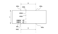
- FIG. 12 is a side view conceptually showing the insulation film 400 used in the stator 1 according to Embodiment 1.
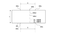
- FIG. FIG. 13 is a side view conceptually showing another example of insulating film 400 used in stator 1 according to the first embodiment.
- a sheet of insulating film 400 before being cut has a cuttable portion 400b in the state of the winding posture of the stator 1 in which the windings 4 are wound around the split stator core 2 .
- the cuttable portion 400b is a portion formed on the insulating film 400 and processed to be easily cut.
- the cuttable portion 400b is formed in a line extending from the upper and lower ends of the insulating film 400. As shown in FIG. The cuttable portion 400b is formed in the insulating film 400 so as to extend in the axial direction of the stator 1. As shown in FIG. 12, the cuttable portion 400b is formed on the left side of the central portion of the insulating film 400, and in FIG. 13, the cuttable portion 400b is formed on the right side of the central portion of the insulating film 400. there is The insulating film 400 may have a cuttable portion 400b on either the left or right side of the central portion. That is, the insulating film 400 may have a cuttable portion 400b corresponding to either the left core-back portion 2a1 or the right core-back portion 2a2.
- the cuttable portion 400b has a cutting portion 400b1 from which the insulating film 400 has been cut and a connecting portion 400b2 from which the insulating film 400 has not been cut.
- cut portions 400b1 and connecting portions 400b2 are alternately formed in the axial direction of the stator 1.
- the insulating film 400 can be cut by cutting the cuttable portion 400b, that is, by cutting the connecting portion 400b2. Therefore, the insulating films 400 respectively arranged on the adjacent split stator cores 2 are formed from one insulating film 400 .
- the insulating film 400 is one sheet when installed, but is divided into two sheets by being cut by the cuttable portion 400b.
- the insulating film 400 has an engaging portion 400e.
- Engaging portion 400 e is a portion that engages with fixing claw 310 of insulator 300 when insulating film 400 is attached to stator 1 .
- the insulating film 400 In the direction perpendicular to the axial direction of the stator 1, the insulating film 400 has two engaging portions 400e at its upper end. The length between the two engaging portions 400e at the upper end is the insulating film circumferential direction length D [mm] described above.
- the insulating film 400 has two engaging portions 400e at its lower end. The length between the two engaging portions 400e at the lower ends is the insulating film circumferential direction length D [mm] described above.
- the thickness of the insulating film 400 is assumed to be f [mm].
- the length of the insulating film 400 in the axial direction of the stator 1 is defined as the axial length h [mm].
- the length of the cut portion 400b1 in the axial direction of the stator 1 is defined as a cut length d [mm].
- the length of the connection portion 400b2 is assumed to be a connection length e [mm].
- the insulating film 400 has a cuttable portion 400b formed at a position where the cutting distance c is greater than half the gap distance b. That is, the insulating film 400 has the cuttable portion 400b formed on a line that satisfies the formula of cutting distance c>gap distance b/2.
- the position of the cuttable portion 400b is the left connecting end portion 2a13 of the left core-back portion 2a1 of the split stator core 2 and the left connecting side end portion 2a13. It can exist between the tooth side surface 2b11.
- the position of the cuttable portion 400b is the right connecting end portion 2a23 of the right core-back portion 2a2 of the split stator core 2. and the right tooth side surface 2b21.
- the creepage distance ms which is the sum of the edge length a and half the gap distance b minus the cutting distance c and the thickness f, is predetermined by the JIS standard.
- the cuttable portion 400b is formed at a position larger than the minimum creepage distance provided. That is, the insulating film 400 has the cuttable portion 400b formed on a line that satisfies the following equation: end length a+gap distance b/2 ⁇ cutting distance c+thickness f>predetermined minimum creepage distance.
- Creepage distance ms is the shortest distance along the surface of insulating film 400 from winding end portion 4g to core-back portion 2a when stator 1 is viewed in the axial direction of stator 1 .
- the cuttable portion 400b of the insulating film 400 is formed such that the connecting length e is smaller than the cutting length d. That is, the cuttable portion 400b is formed so as to satisfy the expression of connection length e ⁇ cut length d.
- the insulation film 400 is formed so that the size obtained by dividing the length h in the axial direction by the sum of the connection length e and the cut length d is 2 [mm] or more. That is, the cuttable portion 400b is formed so as to satisfy the following formula: axial length h/(connection length e+cut length d) ⁇ 2 [mm].
- the cutting of the insulating film 400 will be described using the state of the winding posture of the stator 1 shown in FIG.
- a stator 1 shown in FIG. The state of the winding posture of the stator 1 turned 40 degrees to the center is shown.
- the number of split stator cores 2 is not limited to nine.
- the turning direction of the stator core segments 2 is turned around the connecting portions 51.
- the cuttable portion 400b of the insulating film 400 is cut by the tensile force of .
- a tensile force acts on the insulating film 400 when the split stator core 2 is turned around the connecting portion 51 so as to widen the space between the left tooth portion 2b1 and the right tooth portion 2b2. That is, if split stator core 2 is turned around coupling portion 51 so that the angle between left tooth portion 2b1 and right tooth portion 2b2 widens, a tensile force acts on insulating film 400.
- a restoring force acts on the portion where the insulating film 400 is fixed by the windings 4 and the portion where the insulating film 400 is supported by the fixing claws 310 so that the pulled insulating film 400 tries to return to its original state.
- the part opposes the restoring force.
- FIG. 14 is a conceptual diagram explaining a fractured surface after cutting the insulating film 400 used in the stator 1 according to the first embodiment.
- the cut surfaces of the insulating film 400 after cutting are such that when the ends 302 of both cut insulating films 400 are brought together, the uneven portions 303 are aligned.
- the end portions 302 of the insulating films 400 adjacent to each other in an overlapping state have uneven portions 303 that match the uneven shape of the end portions 302 so as to fit each other.
- An end portion 302 of the insulating film 400 is cut off at a cuttable portion 400b.
- the uneven portion 303 is formed in the connecting portion 400b2 (see FIG. 12).
- the insulating film 400 is in contact with the core-back portion 2a, and is arranged on adjacent split stator cores 2 among the plurality of split stator cores 2, respectively, and forms uneven portions 303 whose ends have the same uneven shape. provided at each end 302 .
- the insulating film 400 is arranged so that the edge 302 of the insulating film 400 having the uneven portion 303 overlaps the other insulating film 400 adjacent thereto.
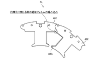
- FIG. 15 is a conceptual diagram explaining winding of the insulating film 400L in the winding process of the stator 1L according to the comparative example.
- FIG. 16 is a conceptual diagram illustrating how the insulating film 400L gets caught when the split stator core 2 of the stator 1L according to the comparative example is annularly closed.
- a stator 1L according to a comparative example that does not use the insulator 300 and the insulating film 400 according to the first embodiment will be described with reference to FIGS. 15 and 16.
- FIG. 15 is a conceptual diagram explaining winding of the insulating film 400L in the winding process of the stator 1L according to the comparative example.
- FIG. 16 is a conceptual diagram illustrating how the insulating film 400L gets caught when the split stator core 2 of the stator 1L according to the comparative example is annularly closed.
- the stator of the rotary electric machine used in the compressor can improve copper loss and improve performance.
- Methods for improving the effective cross-sectional area of windings include reducing the amount of insulating material used to insulate the windings and the stator core in slots, or adopting a split stator core for the stator core and increasing the number of windings. It is effective to reduce the dead space during line.
- both of these methods are employed, like the stator 1L according to the comparative example of FIG. Risk of interference with winding equipment.
- the stator 1L according to the comparative example of FIG. There is a risk of adversely affecting the shape of the product.
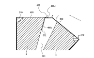
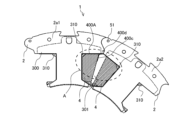
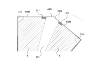
- FIG. 17 is a conceptual diagram showing an overlapping state of insulating films 400 of stator 1 according to the first embodiment.
- 18 is an enlarged view of the slot 301 portion of the stator 1 according to Embodiment 1, and is an enlarged view of the A portion of the stator 1 shown in FIG. 17.
- FIG. The insulating films 400 contact the core-back portions 2a in the slots 301 and are arranged respectively on the adjacent split stator cores 2, and the adjacent insulating films 400 are arranged in an overlapping state.
- the insulating film 400 is in contact with the core-back portion 2a, and is arranged on adjacent split stator cores 2 among the plurality of split stator cores 2, respectively, and forms uneven portions 303 whose ends have the same uneven shape. provided at each end 302 .
- the insulating film 400 is arranged so that the end portion 302 of the insulating film 400 having the uneven portion 303 overlaps the adjacent insulating film 400 . Since the insulating films 400 are arranged in the above state, the insulating films 400 overlap the gaps between the adjacent split stator cores 2 . Therefore, in the stator 1, when the split stator cores 2 are bent into an annular shape, the insulation film 400 is prevented from being caught in the gap between the adjacent split stator cores 2 and the insulation film 400 is caught after the winding. can.
- the stator 1 is provided with a film length such that the insulating film 400 does not bend during the winding posture. Due to this configuration, the stator 1 can prevent the insulating film 400 from being entangled during winding. On the other hand, the state in which the insulating film 400 is not bent at all cannot be produced in terms of manufacturing, and the insulating film 400 is slightly bent.
- the insulating film is composed of a single sheet of insulating film that does not have the cuttable portion 400b, that is, the insulating film used for the adjacent split stator core 2 is composed of a sheet of uncut insulating film.
- the cuttable portion 400b is provided at a position where the insulating film 400 overlaps the gap between the split stator cores 2 in the winding posture, and the stator 1 is bent into an annular shape.
- the insulating film 400 is cut at the cuttable portion 400b before being cut. Since the end 302 of the cut insulating film 400 of the stator 1 is open, the cut portion does not bend. Therefore, when the stator 1 is bent into an annular shape, the insulation film 400 is unlikely to be bent. can be suppressed.
- the insulating films 400 are in contact with the core-back portions 2a at the slots 301 and are arranged on the adjacent split stator cores 2, respectively, and the adjacent insulating films 400 are arranged in an overlapping state.
- the insulating films 400 are arranged in the above state, the insulating films 400 overlap the gaps between the adjacent split stator cores 2 . Therefore, in the stator 1, when the split stator cores 2 are bent into an annular shape, the insulation film 400 is prevented from being caught in the gap between the adjacent split stator cores 2 and the insulation film 400 is caught after the winding. can.
- the ends 302 of the insulating films 400 adjacent to each other in an overlapping state have uneven portions 303 in which the uneven shapes of the ends 302 match each other so that the ends 302 fit into each other.
- the insulating film 400 can have uneven portions 303 in which the uneven shapes of the end portions 302 match each other so that each insulating film 400 is pulled and cut.
- the insulating film 400 has a cuttable portion 400b, and an end portion 302 of the insulating film 400 is cut off at the cuttable portion 400b. Since the insulating film 400 has the cuttable portion 400b, the insulating film 400 can be easily cut at the intended position.
- the stator 1 is formed so as to satisfy the relationship of cutting distance c>gap distance b/2.
- the cutting position of the insulating film 400 formed by the cuttable portion 400b is not the gap between the adjacent split stator cores 2, It can exist on the core back portion 2a.
- the stator 1 is formed so as to satisfy the formula: end length a+gap distance b/2 ⁇ cutting distance c+thickness f>predetermined minimum creepage distance. Therefore, in the stator 1, after the insulating film 400 is cut at the cuttable portion 400b, the creepage distance ms derived from the edge length a+gap distance b/2 ⁇ cutting distance c+thickness f ensures the minimum creepage distance. can do.
- the stator 1 is formed so that the cuttable portion 400b of the insulating film 400 satisfies the equation: connecting length e ⁇ cutting length d. Therefore, the insulating film 400 can be easily cut at the cuttable portion 400b by a tensile force perpendicular to the cuttable portion 400b.
- the stator 1 is formed so that the cuttable portion 400b of the insulating film 400 satisfies the formula: axial length h/(connection length e+cut length d) ⁇ 2. Insulating film 400 satisfies the above formula, so that in cuttable portion 400b, cut portion 400b1, which is a portion where insulating film 400 is cut, and connecting portion 400b2, which is a portion where insulating film 400 is not cut. At least two sets are provided. Therefore, the insulating film 400 is less likely to be deformed before the cuttable portion 400b is cut, and the shape of the insulating film 400 is easily maintained.
- the stator 1 is formed so as to satisfy the relationship: left core-back length A + right core-back length B + distance between core-back portion end points C ⁇ length D in the circumferential direction of the insulating film. That is, the insulating film circumferential length D is obtained by adding the left core-back length A, the right core-back length B, and the core-back portion end-to-end distance C when the stator 1 is in the winding posture. Longer than length. Therefore, the stator 1 is changed from the state in which the split stator cores 2 are arranged in an annular shape as shown in FIG. The insulating film 400 does not generate a force that hinders the rotation of the adjacent split stator cores 2 with respect to the rotation.
- the stator 1 is formed so as to satisfy the relationship: insulation film circumferential length D ⁇ 2 ⁇ (left core-back length A+right core-back length B+distance between core-back end points C). That is, the insulating film circumferential length D is shorter than twice the sum of the left core-back length A, the right core-back length B, and the distance C between the core-back end points. It's becoming Therefore, when the stator 1 is in the winding position, the insulating film 400 can be restrained from bending in an arc toward the center of the stator 1. When the insulating film 400 and the insulator 300 are assembled with the split stator core 2, the following can be achieved. It becomes easy to attach the insulating film 400 to the fixing claw 310 to be connected. In addition, the stator 1 is provided with a film length such that the insulating film 400 does not bend during the winding posture. Due to this configuration, the stator 1 can prevent the insulating film 400 from being entangled during winding.
- the stator 1 has a cutting position 400d of the insulating film 400 at a position where the insulating film 400 satisfies the minimum creepage distance, and the insulating film 400 is formed by the cuttable portion 400b on the core-back portion 2a of the split stator core 2. cutting position 400d. That is, the cutting position 400d of the insulating film 400 by the cuttable portion 400b exists on the core-back portion 2a instead of the gap between the adjacent split stator cores 2.
- the stator 1 prevents part of the flexed insulating film 400 from being caught in the gap between the adjacent stator segment cores 2 when the stator segment cores 2 are bent into an annular shape.
- the cut portion of the insulating film 400 is a free end. Therefore, there is no force to fix the winding nozzle on the winding track. Therefore, in the stator 1, there is no fear of damage to the tips of the winding nozzles, and the insulation by the insulating film 400 can be used regardless of the winding orientation to achieve improved performance due to high-density winding.
- FIG. 19 is a conceptual diagram illustrating cuttable portion 400b of insulating film 400A using a plan view and a side view of the inner diameter side of stator 1 according to the second embodiment.
- Components having the same functions and actions as those of the stator 1 according to Embodiment 1 are denoted by the same reference numerals, and descriptions thereof are omitted.
- the second embodiment will be described with a focus on the differences from the first embodiment, and the configurations not described in the second embodiment are the same as those of the first embodiment.
- the stator 1 according to Embodiment 2 specifies the forming direction of the cuttable portion 400b of the insulating film 400A.
- the cuttable portions 400b of the insulating film 400A are formed on lines such that the core-back portions 2a of the split stator cores 2 closest to the upper and lower ends of the insulating film 400A are different.
- the cuttable portions 400b are formed so that the split stator cores 2 whose upper ends are closest to the adjacent split stator cores 2 are different from the split stator cores 2 whose lower ends are closest. . That is, the cuttable portion 400b of the insulating film 400A is formed to be inclined with respect to the center line 51a passing through the center of the connecting portion 51. As shown in FIG. Alternatively, the cuttable portion 400b of the insulating film 400A is formed so as to be inclined with respect to the axial direction of the stator 1. As shown in FIG.
- the upper end of the cuttable portion 400b is closer to the left core-back portion 2a1 and the lower end of the cuttable portion 400b is closer to the right core-back portion 2a2, but the reverse is also possible. That is, the upper end of the cuttable portion 400b may be closer to the right core-back portion 2a2, and the lower end of the cuttable portion 400b may be closer to the left core-back portion 2a1.
- FIG. 20 is a conceptual diagram showing an overlapping state of insulating films 400A of stator 1 according to the second embodiment.
- 21 is an enlarged view of the slot 301 portion of the stator 1 according to Embodiment 2, showing the relationship between the insulating film 400A on one end side and the windings 4 in the portion A shown in FIG. It is a diagram.
- FIG. 22 is an enlarged view of the slot 301 portion of the stator 1 according to Embodiment 2, showing the relationship between the insulating film 400A on the other end side of the portion A shown in FIG. It is a diagram.
- the stator 1 has a cutting position 400d of the insulating film 400A at a position where the insulating film 400A satisfies the minimum creepage distance, and the insulating film 400A is formed on the core-back portion 2a of the split stator core 2 by the cuttable portion 400b. cutting position 400d. That is, the cutting position 400d of the insulating film 400A by the cuttable portion 400b exists on the core-back portion 2a rather than in the gap between the adjacent split stator cores 2.
- the insulating film 400A overlaps the gap between the adjacent split stator cores 2 as shown in FIGS. Become. Moreover, as shown in FIGS. 21 and 22, an overlap portion 400c including the cut end portion of the insulating film 400A is arranged to partially overlap the winding wire 4. As shown in FIG. Therefore, the stator 1 prevents part of the flexed insulating film 400A from being caught in the gap between the adjacent stator segment cores 2 when the stator segment cores 2 are bent into an annular shape.
- the cuttable portions 400b are arranged in the stator 1 such that the split stator cores 2 whose upper ends are closest to the adjacent split stator cores 2 are different from the split stator cores 2 whose lower ends are closest. is formed so as to be inclined with respect to the axial direction of As shown in FIG. 21, the upper end of the cuttable portion 400b is close to the left core-back portion 2a1, so that the overlap portion 400c including the cut end of the insulating film 400A is the left tooth portion 2b1. It is arranged so as to overlap a part of the winding 4 which is wound in the direction of . Also, in FIG.
- the overlap portion 400c including the cut end of the insulating film 400A is positioned at the right tooth portion 2b2. A portion of the wound winding 4 is overlapped.
- the cuttable portion 400b is cut obliquely. Since a part of the insulating film 400A is not removed, the gaps between the adjacent split stator cores 2 are covered immediately after the winding is completed. Therefore, compared with the stator 1 according to the first embodiment, the stator 1 according to the second embodiment can further reduce the risk of the insulating film 400A getting caught.
- FIG. 23 is a conceptual diagram illustrating cuttable portion 400b of insulating film 400B using a plan view and a side view of the inner diameter side of stator 1 according to the third embodiment.
- FIG. 24 is a side view conceptually showing insulating film 400B used in stator 1 according to the third embodiment.
- Components having the same functions and actions as those of the stator 1 according to Embodiments 1 and 2 are denoted by the same reference numerals, and descriptions thereof are omitted.
- the following description focuses on the differences of the third embodiment from the first and second embodiments, and the configurations not described in the third embodiment are the same as those of the first and second embodiments.
- Embodiment 3 further specifies the configuration of insulator 300 and the configuration of insulating film 400 .
- the insulating film 400B is arranged so that the cutting positions of the cuttable portion 400b in the radial direction of the stator 1 are positioned at the left core-back portion 2a1 and the right core-back portion 2a2. are formed with two cuttable portions 400b. That is, in the stator 1, the cuttable portions 400b are formed in the core-back portions 2a of the split stator cores 2 adjacent to each other in both left and right directions, at positions facing the core-back portions 2a forming the slots 301, respectively. .
- the insulator 300 which is an insulating member, has two fixing claws, a fixing claw 310 and a second fixing claw 311, as shown in FIG.
- the second fixing claw 311 is formed on the core-back side wall portion 321 (see FIG. 3).
- the second fixing claw 311 is provided so as to be positioned on the side surface of the core back portion 2a forming the slot 301 when the insulator 300 is attached to the split stator core 2 .
- the second fixing claw 311 is formed closer to the connecting portion 51 than the fixing claw 310 is.
- the second fixing claw 311 has strength equivalent to that of the fixing claw 310 .
- the second fixing claw 311 is formed closer to the connecting side of the plurality of split stator cores 2 than the fixing claw 310, and supports the insulating film 400 arranged at a position facing the core back portion 2a.
- FIG. 25 is a plan view showing a state where insulators 300 and windings 4 are attached to split stator cores 2 of stator 1 according to the third embodiment.
- FIG. 26 is an enlarged plan view showing a portion B of the stator 1 shown in FIG. 25.
- FIG. 26 in the core-back portion 2a, the portion facing the winding wire 4 in the slot 301 with the insulator 300 interposed therebetween is a winding-arrangeable portion 330 of the core-back portion 2a.
- a winding arrangement end portion 335 shown in FIG. 26 is an end portion where the winding wire 4 can be arranged in the circumferential direction of the core back portion 2a.
- the windings 4 can be arranged between the tooth portions 2b and the winding arrangementable portions 330 in the slots 301 (see FIG. 4).
- the circumferential direction of the core-back portion 2a and the circumferential direction of the winding-arrangeable portion 330 are the directions along the left-side core-back side surface 2a11 in plan view of the stator 1. (see FIG. 8).
- the circumferential direction of the winding-arrangeable portion 330 is the direction along the right core-back side surface 2a21 in plan view of the stator 1 (see FIG. 8).
- the length in the circumferential direction of the winding arrangeable portion 330 is assumed to be the winding arrangeable length j [mm].
- the circumferential length of the fixing claw 310 is defined as the core portion claw length k [mm].
- the circumferential direction of the fixed claw 310 is the direction along the left core-back side surface 2a11 in plan view of the stator 1 (see FIG. 8).
- the circumferential direction of the fixing claw 310 is the direction along the right core-back side surface 2a21 in plan view of the stator 1 (see FIG. 8).
- the length in the radial direction of the fixed claw 310 is defined as the tooth portion claw length l [mm].
- the radial direction of the fixing claw 310 is the direction along the left tooth side surface 2b11 in plan view of the stator 1 (see FIG. 8), and is along the central axis of the tooth portion 2b. It is the direction along
- the radial direction of the fixing claw 310 is the direction along the right tooth side surface 2b21 in plan view of the stator 1 (see FIG. 8), and is the direction along the center of the tooth portion 2b. It is the direction along the axis.
- the circumferential length of the second fixed claw 311 is defined as the second core part claw length m [mm].
- the circumferential direction of the second fixing claw 311 is the direction along the left core-back side surface 2a11 in plan view of the stator 1 (see FIG. 8).
- the circumferential direction of the second fixing claw 311 is the direction along the right core-back side surface 2a21 in plan view of the stator 1 (see FIG. 8).
- the length of the second fixed claw 311 in the radial direction is defined as the second tooth portion claw length n [mm].
- the radial direction of the second fixing claw 311 is the direction along the left tooth side surface 2b11 in plan view of the stator 1 (see FIG. 8), and is the center of the tooth portion 2b. It is the direction along the axis.
- the radial direction of the second fixing claw 311 is the direction along the right tooth side surface 2b21 in plan view of the stator 1 (see FIG. 8). is the direction along the central axis of
- the stator 1 is formed so that the length obtained by subtracting the core claw length k from the winding dispositionable length j is equal to or longer than the second core claw length m. Further, the stator 1 is formed so that the second core portion claw length m is longer than the core portion claw length k. That is, the stator 1 is formed so as to satisfy the following equation: length of possible winding arrangement j ⁇ core claw length k ⁇ second core claw length m ⁇ core claw length k.
- stator 1 is formed such that the tooth portion claw length l is longer than the second tooth portion claw length n. Further, the stator 1 is formed such that the claw length n of the second tooth portion is 0.3 [mm] or longer. That is, the stator 1 is formed so as to satisfy the following equation: tooth claw length l ⁇ second tooth claw length n ⁇ 0.3 [mm]. 0.3 [mm] is set based on the minimum thickness of the insulator 300 when the insulator 300, which is a motor insulating member, is injection molded.
- FIG. 27 is a conceptual diagram showing insulating film 400B of stator 1 according to the third embodiment. 28 is an enlarged view of the slot 301 portion of the stator 1 according to Embodiment 3, and is an enlarged view of the A portion of the stator 1 shown in FIG. 27. FIG.
- the stator 1 has a cutting position 400d of the insulating film 400B at a position where the insulating film 400B satisfies the minimum creepage distance, and the insulating film 400B is formed on the core-back portion 2a of the split stator core 2 by the cuttable portion 400b. cutting position 400d. That is, the cutting position 400d of the insulating film 400B by the cuttable portion 400b exists on the core-back portion 2a instead of the gap between the adjacent split stator cores 2.
- the cuttable portions 400b are formed at positions facing the core back portions 2a of the adjacent split stator cores 2 forming the slots 301, respectively. That is, the stator 1 is formed so that the cuttable portions 400b are positioned on both the left and right core-back portions 2a forming the slots 301. As shown in FIG.
- the insulating film 400B can be cut at a portion between the two cuttable portions 400b to cover the gaps of the stator core segments 2 until the stator core segments 2 are arranged in an annular shape after the insulating film 400B is cut. There is no insulating film 400B. Therefore, stator 1 according to Embodiment 3 can suppress the occurrence of entrapment of insulating film 400B.
- a pair of insulators 300 are formed closer to the connecting side of the plurality of split stator cores 2 than the fixing claws 310, and the second fixing claws 311 support the insulating film 400B arranged at a position facing the core back portion 2a.
- the stator 1 has two fixed claws, ie, the fixed claw 310 and the second fixed claw 311 .
- the stator 1 improves the function of preventing the insulating film 400B from being lifted up. , the pulling force of the insulating film 400 can be improved.
- the stator 1 is formed so as to satisfy the following equation: winding dispositionable length j ⁇ core claw length k ⁇ second core claw length m ⁇ core claw length k.
- winding dispositionable length j ⁇ core claw length k ⁇ second core claw length m ⁇ core claw length k When the stator 1 is formed so as to satisfy the following equation: length of possible winding arrangement j ⁇ core claw length k ⁇ second core claw length m ⁇ core claw length k effect.
- a second fixing claw 311 having strength equivalent to that of the fixing claw 310 can be arranged.
- the stator 1 can prevent the insulating film 400B from rising to the winding region 401 (FIG. 15) by arranging the second fixing claw 311 at the position in addition to the fixing claw 310 .
- the insulator 300 which is an insulating member is injection molded. It is possible to ensure moldability when forming.
- a rotating electric machine 103 which is an electric motor of the compressor 130, a compressor 130 having the rotating electric machine 103, and a refrigeration cycle apparatus 200 having the compressor 130 are provided with the stator 1 according to Embodiments 1 to 3. is.
- Rotating electric machine 103 which is an electric motor of compressor 130, compressor 130 having rotating electric machine 103, and refrigeration cycle device 200 having compressor 130 can obtain the same effect as stator 1 of Embodiments 1 to 3. can.
Landscapes
- Engineering & Computer Science (AREA)
- Power Engineering (AREA)
- Insulation, Fastening Of Motor, Generator Windings (AREA)
- Iron Core Of Rotating Electric Machines (AREA)
Abstract
Description
[圧縮機130の構成]
図1は、実施の形態1に係る圧縮機130の縦断面図である。図1を用いて、密閉型圧縮機である圧縮機130について説明する。圧縮機130は、低温且つ低圧の冷媒を吸入し、吸入した冷媒を圧縮し、高温且つ高圧の冷媒を吐出する。
圧縮機構部102は、回転電機103により駆動し、外部から吸入した流体を圧縮する。圧縮機構部102は、回転電機103から供給された回転駆動力により、吸入連結管128から密閉容器101の低圧空間に吸入された低圧のガス冷媒を高圧のガス冷媒に圧縮し、圧縮した高圧のガス冷媒を圧縮機構部102の上方に吐出する。
回転電機103は、密閉容器101内に配置される電動機であり、圧縮機構部102を動かすために用いられる。回転電機103は、外部電源から供給された電力を用いてクランクシャフト104に回転駆動力を発生させ、クランクシャフト104を介して圧縮機構部102に回転駆動力を伝達するモータである。回転電機103には、例えば、ブラシレスDCモータが用いられる。
次に、本実施の形態の圧縮機130の動作について説明する。回転電機103の駆動によりクランクシャフト104が回転すると、クランクシャフト104と共に、シリンダ105の内部に収容された偏心部104c及びローリングピストン109が偏心回転する。偏心部104c及びローリングピストン109の偏心回転により、ローリングピストン109の外周面は、シリンダ105の中空部分において、シリンダ105の内側面に接触して移動する。
図2は、実施の形態1に係る圧縮機130が接続される空気調和機等の冷凍サイクル装置200の概略構成図である。冷凍サイクル装置200は、圧縮機130、流路切替装置133、室外側熱交換器134、減圧装置135、及び室内側熱交換器136を備えている。また、冷凍サイクル装置200は、吸入マフラー127を備えており、吸入マフラー127は、圧縮機130の吸入側に接続されている。なお、冷凍サイクル装置200は、吸入マフラー127を備えていることが望ましいが、吸入マフラー127を備えていなくてもよい。
冷凍サイクル装置200が空気調和機であり、空気調和機が暖房運転を行う場合の冷凍サイクル装置200の動作について説明する。空気調和機の暖房運転では、流路切替装置133は、図2の実線側に回路を形成するように、流路切替装置133に接続された配管同士を接続する。
図3は、実施の形態1に係る圧縮機130の回転電機103に用いられる固定子1の一部を示す斜視図である。図4は、実施の形態1に係る圧縮機130の回転電機103に用いられる固定子1の一部を示す平面図である。なお、図4では、分割固定子鉄心2を説明するためにインシュレータ300、絶縁フィルム400、及び巻線4の図示を省略している。図3及び図4を用いて、回転電機103に用いられる固定子1について説明する。
図17は、実施の形態1に係る固定子1の絶縁フィルム400のオーバーラップ状態を示す概念図である。図18は、実施の形態1に係る固定子1のスロット301部分の拡大図であって、図17で示した固定子1のA部の拡大図である。絶縁フィルム400は、スロット301において、コアバック部2aに接触し、隣接する分割固定子鉄心2にそれぞれ配置されており、隣り合う絶縁フィルム400同士が重なった状態で配置されている。
図19は、実施の形態2に係る固定子1の平面図と内径側の側面図とを用いた絶縁フィルム400Aの切断可能部400bを説明する概念図である。実施の形態1に係る固定子1と同一の機能及び作用を有する構成要素については、同一の符号を付してその説明を省略する。以下、実施の形態2が実施の形態1と異なる点を中心に説明し、実施の形態2で説明しない構成は実施の形態1と同様である。実施の形態2に係る固定子1は、絶縁フィルム400Aの切断可能部400bの形成方向を特定するものである。
図20は、実施の形態2に係る固定子1の絶縁フィルム400Aのオーバーラップ状態を示す概念図である。図21は、実施の形態2に係る固定子1のスロット301部分の拡大図であって、図20に示すA部における一方の端部側の絶縁フィルム400Aと巻線4との関係を示す拡大図である。図22は、実施の形態2に係る固定子1のスロット301部分の拡大図であって、図20に示すA部における他方の端部側の絶縁フィルム400Aと巻線4との関係を示す拡大図である。
図23は、実施の形態3に係る固定子1の平面図と内径側の側面図とを用いた絶縁フィルム400Bの切断可能部400bを説明する概念図である。図24は、実施の形態3に係る固定子1に用いられる絶縁フィルム400Bを概念的に表した側面図である。実施の形態1及び実施の形態2に係る固定子1と同一の機能及び作用を有する構成要素については、同一の符号を付してその説明を省略する。以下、実施の形態3が実施の形態1及び実施の形態2と異なる点を中心に説明し、実施の形態3で説明しない構成は実施の形態1及び実施の形態2と同様である。実施の形態3は、インシュレータ300の構成と、絶縁フィルム400の構成を更に特定するものである。
図27は、実施の形態3に係る固定子1の絶縁フィルム400Bを示す概念図である。図28は、実施の形態3に係る固定子1のスロット301部分の拡大図であって、図27で示した固定子1のA部の拡大図である。
Claims (14)
- 回転電機に用いられる固定子であって、
互いに連結されて環状に配置される複数の分割固定子鉄心と、
絶縁部材であって、前記複数の分割固定子鉄心のそれぞれの分割固定子鉄心の、軸方向の両端面に配置される一対のインシュレータと、
前記複数の分割固定子鉄心の、隣接する分割固定子鉄心間の空間であるスロットを形成する面に装着され、前記複数の分割固定子鉄心のそれぞれに巻かれる巻線と、前記複数の分割固定子鉄心とを絶縁する絶縁フィルムと、
を備え、
前記複数の分割固定子鉄心のそれぞれは、
前記固定子の周方向に延在するコアバック部と、
前記コアバック部の中央部から前記固定子の中心方向に突出し、前記巻線が巻き付けられるティース部と、
を有し、
前記絶縁フィルムは、
前記コアバック部に接触し、前記複数の分割固定子鉄心のうち隣接する分割固定子鉄心にそれぞれ配置されており、その端部同士の凹凸形状が一致する凹凸部をそれぞれの端部に備えており、
前記凹凸部を有する前記絶縁フィルムの前記端部が隣接する他方の前記絶縁フィルムと重なり配置されている固定子。 - 前記隣接する分割固定子鉄心にそれぞれ配置されている前記絶縁フィルムは、一枚の絶縁フィルムが2枚に切断されて形成されており、
前記複数の分割固定子鉄心に前記巻線が巻き付けられる前記固定子の巻線姿勢の状態において、前記一対のインシュレータに固定されている一枚の前記絶縁フィルムは、前記絶縁フィルムが切り離された切断部と、前記絶縁フィルムが切り離されていない接続部とが交互に形成された切断可能部を有しており、
前記絶縁フィルムの前記端部は、
前記切断可能部で切り離されて形成されている請求項1に記載の固定子。 - 前記一対のインシュレータは、
前記一対のインシュレータが前記複数の分割固定子鉄心のそれぞれに装着されている場合に、前記コアバック部と前記ティース部との交差部分であって、前記ティース部の根元部分に前記絶縁フィルムを固定する固定ツメを有し、
前記絶縁フィルムは、
前記スロットにおいて、前記コアバック部に接触し、前記隣接する分割固定子鉄心にそれぞれ配置されており、隣り合う前記絶縁フィルム同士が重なった状態で配置されている請求項1又は2に記載の固定子。 - 回転電機に用いられる固定子であって、
互いに連結されて環状に配置される複数の分割固定子鉄心と、
絶縁部材であって、前記複数の分割固定子鉄心のそれぞれの分割固定子鉄心の、軸方向の両端面に配置される一対のインシュレータと、
前記複数の分割固定子鉄心の、隣接する分割固定子鉄心間の空間であるスロットを形成する面に装着され、前記複数の分割固定子鉄心のそれぞれに巻かれる巻線と、前記複数の分割固定子鉄心とを絶縁する絶縁フィルムと、
を備え、
前記複数の分割固定子鉄心のそれぞれは、
前記固定子の周方向に延在するコアバック部と、
前記コアバック部の中央部から前記固定子の中心方向に突出し、前記巻線が巻き付けられるティース部と、
を有し、
前記一対のインシュレータは、
前記一対のインシュレータが前記複数の分割固定子鉄心のそれぞれに装着されている場合に、前記コアバック部と前記ティース部との交差部分であって、前記ティース部の根元部分に前記絶縁フィルムを固定する固定ツメを有し、
前記絶縁フィルムは、
前記スロットにおいて、前記コアバック部に接触し、前記隣接する分割固定子鉄心にそれぞれ配置されており、隣り合う前記絶縁フィルム同士が重なった状態で配置されている固定子。 - 回転電機に用いられる固定子であって、
互いに連結されて環状に配置される複数の分割固定子鉄心と、
絶縁部材であって、前記複数の分割固定子鉄心のそれぞれの分割固定子鉄心の、軸方向の両端面に配置される一対のインシュレータと、
前記複数の分割固定子鉄心の、隣接する分割固定子鉄心間の空間であるスロットを形成する面に装着され、前記複数の分割固定子鉄心のそれぞれに巻かれる巻線と、前記複数の分割固定子鉄心とを絶縁する絶縁フィルムと、
を備え、
前記複数の分割固定子鉄心のそれぞれは、
前記固定子の周方向に延在するコアバック部と、
前記コアバック部の中央部から前記固定子の中心方向に突出し、前記巻線が巻き付けられるティース部と、
を有し、
前記一対のインシュレータは、
前記一対のインシュレータが前記複数の分割固定子鉄心のそれぞれに装着されている場合に、前記コアバック部と前記ティース部との交差部分であって、前記ティース部の根元部分に前記絶縁フィルムを固定する固定ツメを有し、
前記隣接する分割固定子鉄心にそれぞれ配置されている前記絶縁フィルムは、一枚の絶縁フィルムが2枚に切断されて形成されており、
前記複数の分割固定子鉄心に前記巻線が巻き付けられる前記固定子の巻線姿勢の状態において、前記一対のインシュレータに固定されている一枚の前記絶縁フィルムは、前記絶縁フィルムが切り離された切断部と、前記絶縁フィルムが切り離されていない接続部とが交互に形成された切断可能部を複数有しており、
前記絶縁フィルムの端部は、
前記切断可能部で切り離されて形成されており、
前記切断可能部は、
前記スロットを形成する前記隣接する分割固定子鉄心の前記コアバック部と対向する位置にそれぞれ形成されている固定子。 - 前記一対のインシュレータは、
前記固定ツメよりも前記複数の分割固定子鉄心の連結側に形成されており、前記コアバック部と対向する位置に配置された前記絶縁フィルムを支持する第2固定ツメを更に有する請求項3~5のいずれか1項に記載の固定子。 - 前記コアバック部において、前記一対のインシュレータを介して、前記スロット内の前記巻線と対向する部分を、前記コアバック部の巻線配置可能部分とし、
前記巻線配置可能部分の前記周方向の長さを巻線配置可能長さjとし、
前記固定ツメの前記周方向の長さをコア部ツメ長さkとし、
前記固定子の径方向において、前記固定ツメの長さをティース部ツメ長さlとし、
前記第2固定ツメの前記周方向の長さを第2コア部ツメ長さmとし、
前記固定子の径方向において、前記第2固定ツメの長さを第2ティース部ツメ長さnとした場合に、
前記巻線配置可能長さj-前記コア部ツメ長さk≧前記第2コア部ツメ長さm≧前記コア部ツメ長さkの式を満たし、かつ、前記ティース部ツメ長さl≧前記第2ティース部ツメ長さn≧0.3[mm]の式を満たすように形成されている請求項6に記載の固定子。 - 前記ティース部から最も離れた位置に配置される前記巻線と前記絶縁フィルムとが接する部分である巻線終端部から、前記スロットにおいて、前記隣接する分割固定子鉄心の前記コアバック部と接触する部分である鉄心終端までの距離を端部長さaとし、
前記複数の分割固定子鉄心に前記巻線が巻き付けられる前記固定子の巻線姿勢の状態において、隣接する前記コアバック部間の隙間の大きさを隙間距離bとし、
前記固定子の径方向に見た場合に、前記隣接する分割固定子鉄心が連結されている連結部の中心から、前記切断可能部までの距離を切断距離cとし、
前記絶縁フィルムの厚みを厚みfとし、
前記固定子の軸方向において、前記絶縁フィルムの長さを軸方向長hとした場合に、
前記切断距離c>前記隙間距離b/2の式を満たし、かつ、前記端部長さa+前記隙間距離b/2-前記切断距離c+前記厚みf>予め定められた最小沿面距離の式を満たす量に形成されている請求項2又は5に記載の固定子。 - 前記固定子の軸方向において、前記切断部の長さを切断長さdとし、
前記固定子の軸方向において、前記接続部の長さを接続長さeとした場合に、
前記接続長さe<前記切断長さdの式を満たし、かつ、切断可能部400bは、軸方向長h/(接続長さe+切断長さd)≧2[mm]の式をみたすように形成されている請求項8に記載の固定子。 - 前記切断可能部は、
前記隣接する分割固定子鉄心に対して、上端部が最接近する分割固定子鉄心と、下端部最接近する分割固定子鉄心とが異なるように、前記固定子の軸方向に対して傾くように形成されている請求項2に記載の固定子。 - 前記隣接する分割固定子鉄心の一方を分割固定子鉄心の前記コアバック部を左方コアバック部とし、他方の分割固定子鉄心の前記コアバック部を右方コアバック部とし、
前記周方向における前記スロットを形成する前記左方コアバック部の長さを左方コアバック長さAとし、
前記周方向における前記スロットを形成する前記右方コアバック部の長さを右方コアバック長さBとし、
前記複数の分割固定子鉄心に前記巻線が巻き付けられる前記固定子の巻線姿勢の状態において、隣接する前記左方コアバック部と前記右方コアバック部との間に形成された隙間の長さをコアバック部端点間距離Cとし、
前記複数の分割固定子鉄心に前記巻線が巻き付けられる前記固定子の巻線姿勢の状態において、前記左方コアバック部から突出する前記ティース部と、前記右方コアバック部から突出する前記ティース部との間に配置される前記絶縁フィルムの長さを、絶縁フィルム周方向長さDとした場合に、
前記左方コアバック長さA+前記右方コアバック長さB+前記コアバック部端点間距離C<前記絶縁フィルム周方向長さD<2×(前記左方コアバック長さA+前記右方コアバック長さB+前記コアバック部端点間距離C)の式を満たすように形成されている請求項1~10のいずれか1項に記載の固定子。 - 請求項1~11のいずれか1項に記載の固定子と、
前記固定子の内側に設けられ、磁気作用によって回転する回転子と、
を有する回転電機。 - 請求項12に記載の回転電機と、
前記回転電機により駆動し、外部から吸入した流体を圧縮する圧縮機構部と、
前記回転電機及び前記圧縮機構部を収容する密閉容器と、
を備えた圧縮機。 - 請求項13に記載の圧縮機と、
室外空気と内部を流れる冷媒との間で熱交換を行う室外側熱交換器と、
内部を流れる冷媒を減圧する減圧装置と、
室内空気と内部を流れる冷媒との間で熱交換を行う室内側熱交換器と、
を備えた冷凍サイクル装置。
Priority Applications (3)
| Application Number | Priority Date | Filing Date | Title |
|---|---|---|---|
| CN202180100482.6A CN117616670A (zh) | 2021-07-29 | 2021-07-29 | 定子、旋转电机、压缩机以及制冷循环装置 |
| PCT/JP2021/028053 WO2023007644A1 (ja) | 2021-07-29 | 2021-07-29 | 固定子、回転電機、圧縮機、及び冷凍サイクル装置 |
| JP2023537838A JP7511770B2 (ja) | 2021-07-29 | 2021-07-29 | 固定子、回転電機、圧縮機、及び冷凍サイクル装置 |
Applications Claiming Priority (1)
| Application Number | Priority Date | Filing Date | Title |
|---|---|---|---|
| PCT/JP2021/028053 WO2023007644A1 (ja) | 2021-07-29 | 2021-07-29 | 固定子、回転電機、圧縮機、及び冷凍サイクル装置 |
Publications (1)
| Publication Number | Publication Date |
|---|---|
| WO2023007644A1 true WO2023007644A1 (ja) | 2023-02-02 |
Family
ID=85087733
Family Applications (1)
| Application Number | Title | Priority Date | Filing Date |
|---|---|---|---|
| PCT/JP2021/028053 Ceased WO2023007644A1 (ja) | 2021-07-29 | 2021-07-29 | 固定子、回転電機、圧縮機、及び冷凍サイクル装置 |
Country Status (3)
| Country | Link |
|---|---|
| JP (1) | JP7511770B2 (ja) |
| CN (1) | CN117616670A (ja) |
| WO (1) | WO2023007644A1 (ja) |
Cited By (3)
| Publication number | Priority date | Publication date | Assignee | Title |
|---|---|---|---|---|
| WO2025169582A1 (ja) * | 2024-02-07 | 2025-08-14 | 株式会社デンソー | ステータ及びステータの製造方法 |
| WO2025223773A1 (de) | 2024-04-24 | 2025-10-30 | Sew-Eurodrive Gmbh & Co Kg | Elektromotor mit einem stator und einem vom stator radial umgebenen, drehbar gelagerten rotor |
| USD1114441S1 (en) | 2024-02-05 | 2026-02-17 | Beijing Roborock Technology Co., Ltd. | Floor washing appliance |
Citations (13)
| Publication number | Priority date | Publication date | Assignee | Title |
|---|---|---|---|---|
| US5093543A (en) * | 1990-10-26 | 1992-03-03 | Electrical Insulation Suppliers, Inc. | Motor phase insulation article and method of making the same |
| JP2004282928A (ja) * | 2003-03-17 | 2004-10-07 | Mitsubishi Electric Corp | 電動機固定子 |
| JP2005130594A (ja) * | 2003-10-23 | 2005-05-19 | Toyota Motor Corp | 相間絶縁紙 |
| JP2007252030A (ja) * | 2006-03-14 | 2007-09-27 | Mitsuba Corp | インシュレータ及び電動機 |
| JP2008006562A (ja) * | 2006-06-30 | 2008-01-17 | Makita Corp | 電動工具 |
| JP2008278632A (ja) * | 2007-04-27 | 2008-11-13 | Sumitomo Electric Ind Ltd | 分割ステータおよび分割ステータの製造方法 |
| JP2010200469A (ja) * | 2009-02-25 | 2010-09-09 | Nissan Motor Co Ltd | 回転電機のステータ |
| JP2011259614A (ja) * | 2010-06-09 | 2011-12-22 | Mitsubishi Electric Corp | 回転電機の固定子 |
| JP2013132110A (ja) * | 2011-12-20 | 2013-07-04 | Mitsubishi Electric Corp | 電動機の固定子及び絶縁シートの製造方法 |
| JP2017017784A (ja) * | 2015-06-29 | 2017-01-19 | 三菱電機株式会社 | 磁極および磁極を配置した固定子および固定子を備えた回転電機 |
| JP2019062681A (ja) * | 2017-09-27 | 2019-04-18 | 日本電産テクノモータ株式会社 | ステータ及びそのステータを備えたモータ |
| JP2019126178A (ja) * | 2018-01-17 | 2019-07-25 | アイシン精機株式会社 | モーターステーター |
| JP2019180170A (ja) * | 2018-03-30 | 2019-10-17 | アイチエレック株式会社 | 巻線絶縁部材、固定子および電動機 |
-
2021
- 2021-07-29 JP JP2023537838A patent/JP7511770B2/ja active Active
- 2021-07-29 CN CN202180100482.6A patent/CN117616670A/zh active Pending
- 2021-07-29 WO PCT/JP2021/028053 patent/WO2023007644A1/ja not_active Ceased
Patent Citations (13)
| Publication number | Priority date | Publication date | Assignee | Title |
|---|---|---|---|---|
| US5093543A (en) * | 1990-10-26 | 1992-03-03 | Electrical Insulation Suppliers, Inc. | Motor phase insulation article and method of making the same |
| JP2004282928A (ja) * | 2003-03-17 | 2004-10-07 | Mitsubishi Electric Corp | 電動機固定子 |
| JP2005130594A (ja) * | 2003-10-23 | 2005-05-19 | Toyota Motor Corp | 相間絶縁紙 |
| JP2007252030A (ja) * | 2006-03-14 | 2007-09-27 | Mitsuba Corp | インシュレータ及び電動機 |
| JP2008006562A (ja) * | 2006-06-30 | 2008-01-17 | Makita Corp | 電動工具 |
| JP2008278632A (ja) * | 2007-04-27 | 2008-11-13 | Sumitomo Electric Ind Ltd | 分割ステータおよび分割ステータの製造方法 |
| JP2010200469A (ja) * | 2009-02-25 | 2010-09-09 | Nissan Motor Co Ltd | 回転電機のステータ |
| JP2011259614A (ja) * | 2010-06-09 | 2011-12-22 | Mitsubishi Electric Corp | 回転電機の固定子 |
| JP2013132110A (ja) * | 2011-12-20 | 2013-07-04 | Mitsubishi Electric Corp | 電動機の固定子及び絶縁シートの製造方法 |
| JP2017017784A (ja) * | 2015-06-29 | 2017-01-19 | 三菱電機株式会社 | 磁極および磁極を配置した固定子および固定子を備えた回転電機 |
| JP2019062681A (ja) * | 2017-09-27 | 2019-04-18 | 日本電産テクノモータ株式会社 | ステータ及びそのステータを備えたモータ |
| JP2019126178A (ja) * | 2018-01-17 | 2019-07-25 | アイシン精機株式会社 | モーターステーター |
| JP2019180170A (ja) * | 2018-03-30 | 2019-10-17 | アイチエレック株式会社 | 巻線絶縁部材、固定子および電動機 |
Cited By (3)
| Publication number | Priority date | Publication date | Assignee | Title |
|---|---|---|---|---|
| USD1114441S1 (en) | 2024-02-05 | 2026-02-17 | Beijing Roborock Technology Co., Ltd. | Floor washing appliance |
| WO2025169582A1 (ja) * | 2024-02-07 | 2025-08-14 | 株式会社デンソー | ステータ及びステータの製造方法 |
| WO2025223773A1 (de) | 2024-04-24 | 2025-10-30 | Sew-Eurodrive Gmbh & Co Kg | Elektromotor mit einem stator und einem vom stator radial umgebenen, drehbar gelagerten rotor |
Also Published As
| Publication number | Publication date |
|---|---|
| JPWO2023007644A1 (ja) | 2023-02-02 |
| JP7511770B2 (ja) | 2024-07-05 |
| CN117616670A (zh) | 2024-02-27 |
Similar Documents
| Publication | Publication Date | Title |
|---|---|---|
| US11804739B2 (en) | Motor having stator and rotor configured to reduce eddy current loss, and compressor and air conditioner incorporating same | |
| JP7362801B2 (ja) | 電動機、圧縮機、送風機、及び冷凍空調装置 | |
| CN108604835B (zh) | 定子及压缩机 | |
| WO2023007644A1 (ja) | 固定子、回転電機、圧縮機、及び冷凍サイクル装置 | |
| WO2017179115A1 (ja) | 電動機、圧縮機、及び冷凍サイクル装置 | |
| WO2017208291A1 (ja) | 固定子、電動機、圧縮機、及び冷凍空調装置 | |
| WO2020170390A1 (ja) | モータ、圧縮機および空気調和装置 | |
| WO2016063576A1 (ja) | 圧縮機及び圧縮機製造方法 | |
| JP2010279126A (ja) | 電動機固定子鉄心、電動機、密閉型圧縮機、冷凍サイクル装置 | |
| CN106981935B (zh) | 定子铁心、压缩机以及冷冻循环装置 | |
| JP6746000B2 (ja) | 圧縮機および冷凍サイクル装置 | |
| KR102328761B1 (ko) | 압축기 및 냉동 사이클 장치 | |
| WO2023181238A1 (ja) | 固定子、電動機、圧縮機および冷凍サイクル装置 | |
| JP6556342B2 (ja) | 固定子、モータ、圧縮機および冷凍サイクル装置 | |
| KR20200115633A (ko) | 전동기, 압축기, 송풍기, 및 냉동 공조 장치 | |
| WO2025197026A1 (ja) | 固定子、電動機、圧縮機、及び冷凍サイクル装置 | |
| US20250253744A1 (en) | Manufacturing method of stator, stator of electric motor, electric motor, hermetically sealed compressor, and refrigeration cycle apparatus | |
| CN110366809B (zh) | 旋转电机、压缩机以及制冷循环装置 | |
| WO2024218928A1 (ja) | 圧縮機及び冷凍サイクル装置 | |
| WO2023112078A1 (ja) | ステータ、モータ、圧縮機および冷凍サイクル装置 | |
| WO2024195052A1 (ja) | 固定子、電動機、圧縮機、冷凍サイクル装置及び巻線方法 | |
| WO2024157305A1 (ja) | ステータ、電動機、圧縮機および冷凍サイクル装置 | |
| JP2025129706A (ja) | 絶縁フィルム、電動機、圧縮機、及び機器 | |
| JP2026001142A (ja) | 電動機、圧縮機、及び機器 |
Legal Events
| Date | Code | Title | Description |
|---|---|---|---|
| 121 | Ep: the epo has been informed by wipo that ep was designated in this application |
Ref document number: 21951846 Country of ref document: EP Kind code of ref document: A1 |
|
| WWE | Wipo information: entry into national phase |
Ref document number: 2023537838 Country of ref document: JP |
|
| WWE | Wipo information: entry into national phase |
Ref document number: 202180100482.6 Country of ref document: CN |
|
| WWE | Wipo information: entry into national phase |
Ref document number: 2401000407 Country of ref document: TH |
|
| NENP | Non-entry into the national phase |
Ref country code: DE |
|
| 122 | Ep: pct application non-entry in european phase |
Ref document number: 21951846 Country of ref document: EP Kind code of ref document: A1 |