WO2023002657A1 - 磁気記録媒体 - Google Patents
磁気記録媒体 Download PDFInfo
- Publication number
- WO2023002657A1 WO2023002657A1 PCT/JP2022/007137 JP2022007137W WO2023002657A1 WO 2023002657 A1 WO2023002657 A1 WO 2023002657A1 JP 2022007137 W JP2022007137 W JP 2022007137W WO 2023002657 A1 WO2023002657 A1 WO 2023002657A1
- Authority
- WO
- WIPO (PCT)
- Prior art keywords
- magnetic
- recording medium
- particles
- magnetic recording
- fatty acid
- Prior art date
Links
- 239000002245 particle Substances 0.000 claims abstract description 235
- 238000000605 extraction Methods 0.000 claims abstract description 182
- 239000006247 magnetic powder Substances 0.000 claims abstract description 100
- 235000014113 dietary fatty acids Nutrition 0.000 claims description 140
- 229930195729 fatty acid Natural products 0.000 claims description 140
- 239000000194 fatty acid Substances 0.000 claims description 140
- -1 fatty acid ester Chemical class 0.000 claims description 78
- 235000021355 Stearic acid Nutrition 0.000 claims description 71
- 150000004665 fatty acids Chemical class 0.000 claims description 71
- QIQXTHQIDYTFRH-UHFFFAOYSA-N octadecanoic acid Chemical compound CCCCCCCCCCCCCCCCCC(O)=O QIQXTHQIDYTFRH-UHFFFAOYSA-N 0.000 claims description 71
- OQCDKBAXFALNLD-UHFFFAOYSA-N octadecanoic acid Natural products CCCCCCCC(C)CCCCCCCCC(O)=O OQCDKBAXFALNLD-UHFFFAOYSA-N 0.000 claims description 71
- 239000008117 stearic acid Substances 0.000 claims description 71
- QMMJWQMCMRUYTG-UHFFFAOYSA-N 1,2,4,5-tetrachloro-3-(trifluoromethyl)benzene Chemical group FC(F)(F)C1=C(Cl)C(Cl)=CC(Cl)=C1Cl QMMJWQMCMRUYTG-UHFFFAOYSA-N 0.000 claims description 65
- 239000011248 coating agent Substances 0.000 claims description 47
- PNEYBMLMFCGWSK-UHFFFAOYSA-N aluminium oxide Inorganic materials [O-2].[O-2].[O-2].[Al+3].[Al+3] PNEYBMLMFCGWSK-UHFFFAOYSA-N 0.000 claims description 18
- 150000007524 organic acids Chemical group 0.000 claims description 10
- 239000010954 inorganic particle Substances 0.000 claims description 9
- 238000000034 method Methods 0.000 abstract description 58
- 239000002253 acid Substances 0.000 abstract description 9
- 238000005498 polishing Methods 0.000 abstract description 5
- 125000001931 aliphatic group Chemical group 0.000 abstract 5
- 230000002265 prevention Effects 0.000 abstract 1
- 239000010410 layer Substances 0.000 description 241
- 239000000523 sample Substances 0.000 description 62
- 238000005516 engineering process Methods 0.000 description 61
- 239000002585 base Substances 0.000 description 49
- 238000005259 measurement Methods 0.000 description 45
- 229910000859 α-Fe Inorganic materials 0.000 description 42
- 238000000576 coating method Methods 0.000 description 31
- 229910000704 hexaferrum Inorganic materials 0.000 description 31
- 230000006866 deterioration Effects 0.000 description 30
- 239000000463 material Substances 0.000 description 29
- WEVYAHXRMPXWCK-UHFFFAOYSA-N Acetonitrile Chemical compound CC#N WEVYAHXRMPXWCK-UHFFFAOYSA-N 0.000 description 27
- VLKZOEOYAKHREP-UHFFFAOYSA-N n-Hexane Chemical compound CCCCCC VLKZOEOYAKHREP-UHFFFAOYSA-N 0.000 description 27
- 229910018072 Al 2 O 3 Inorganic materials 0.000 description 26
- ZWEHNKRNPOVVGH-UHFFFAOYSA-N 2-Butanone Chemical compound CCC(C)=O ZWEHNKRNPOVVGH-UHFFFAOYSA-N 0.000 description 24
- 239000000203 mixture Substances 0.000 description 24
- 229910052751 metal Chemical group 0.000 description 19
- 229920005989 resin Polymers 0.000 description 19
- 239000011347 resin Substances 0.000 description 19
- 229910052782 aluminium Inorganic materials 0.000 description 18
- 239000002184 metal Chemical group 0.000 description 18
- 238000003860 storage Methods 0.000 description 18
- 239000011230 binding agent Substances 0.000 description 17
- 229910052799 carbon Inorganic materials 0.000 description 17
- UQSXHKLRYXJYBZ-UHFFFAOYSA-N Iron oxide Chemical compound [Fe]=O UQSXHKLRYXJYBZ-UHFFFAOYSA-N 0.000 description 16
- 238000010586 diagram Methods 0.000 description 16
- 238000000349 field-emission scanning electron micrograph Methods 0.000 description 16
- AJCDFVKYMIUXCR-UHFFFAOYSA-N oxobarium;oxo(oxoferriooxy)iron Chemical compound [Ba]=O.O=[Fe]O[Fe]=O.O=[Fe]O[Fe]=O.O=[Fe]O[Fe]=O.O=[Fe]O[Fe]=O.O=[Fe]O[Fe]=O.O=[Fe]O[Fe]=O AJCDFVKYMIUXCR-UHFFFAOYSA-N 0.000 description 16
- OKTJSMMVPCPJKN-UHFFFAOYSA-N Carbon Chemical compound [C] OKTJSMMVPCPJKN-UHFFFAOYSA-N 0.000 description 15
- XAGFODPZIPBFFR-UHFFFAOYSA-N aluminium Chemical compound [Al] XAGFODPZIPBFFR-UHFFFAOYSA-N 0.000 description 15
- 229910017052 cobalt Inorganic materials 0.000 description 15
- 239000010941 cobalt Substances 0.000 description 15
- GUTLYIVDDKVIGB-UHFFFAOYSA-N cobalt atom Chemical compound [Co] GUTLYIVDDKVIGB-UHFFFAOYSA-N 0.000 description 15
- 230000000052 comparative effect Effects 0.000 description 15
- JHIVVAPYMSGYDF-UHFFFAOYSA-N cyclohexanone Chemical compound O=C1CCCCC1 JHIVVAPYMSGYDF-UHFFFAOYSA-N 0.000 description 14
- 235000002597 Solanum melongena Nutrition 0.000 description 13
- 239000003153 chemical reaction reagent Substances 0.000 description 13
- 150000001875 compounds Chemical class 0.000 description 13
- XEEYBQQBJWHFJM-UHFFFAOYSA-N iron Substances [Fe] XEEYBQQBJWHFJM-UHFFFAOYSA-N 0.000 description 13
- YXFVVABEGXRONW-UHFFFAOYSA-N Toluene Chemical compound CC1=CC=CC=C1 YXFVVABEGXRONW-UHFFFAOYSA-N 0.000 description 12
- 238000002360 preparation method Methods 0.000 description 12
- VYPSYNLAJGMNEJ-UHFFFAOYSA-N Silicium dioxide Chemical compound O=[Si]=O VYPSYNLAJGMNEJ-UHFFFAOYSA-N 0.000 description 11
- 239000000314 lubricant Substances 0.000 description 11
- 239000006249 magnetic particle Substances 0.000 description 11
- 239000003973 paint Substances 0.000 description 11
- 239000002904 solvent Substances 0.000 description 11
- 229910052712 strontium Inorganic materials 0.000 description 11
- XLYOFNOQVPJJNP-UHFFFAOYSA-N water Substances O XLYOFNOQVPJJNP-UHFFFAOYSA-N 0.000 description 11
- 239000000654 additive Substances 0.000 description 10
- 238000009826 distribution Methods 0.000 description 10
- 239000000843 powder Substances 0.000 description 10
- 238000004458 analytical method Methods 0.000 description 9
- 239000006229 carbon black Substances 0.000 description 9
- KRKNYBCHXYNGOX-UHFFFAOYSA-N citric acid Chemical compound OC(=O)CC(O)(C(O)=O)CC(O)=O KRKNYBCHXYNGOX-UHFFFAOYSA-N 0.000 description 9
- 238000004891 communication Methods 0.000 description 9
- 239000002131 composite material Substances 0.000 description 9
- 229920001577 copolymer Polymers 0.000 description 9
- 230000000996 additive effect Effects 0.000 description 8
- 238000000089 atomic force micrograph Methods 0.000 description 8
- 238000006243 chemical reaction Methods 0.000 description 8
- 238000004519 manufacturing process Methods 0.000 description 8
- 229920003207 poly(ethylene-2,6-naphthalate) Polymers 0.000 description 8
- 239000011112 polyethylene naphthalate Substances 0.000 description 8
- 238000012545 processing Methods 0.000 description 8
- 238000003917 TEM image Methods 0.000 description 7
- 125000003118 aryl group Chemical group 0.000 description 7
- 230000004888 barrier function Effects 0.000 description 7
- 238000012937 correction Methods 0.000 description 7
- 238000001035 drying Methods 0.000 description 7
- 230000010365 information processing Effects 0.000 description 7
- 150000002739 metals Chemical group 0.000 description 7
- 239000004417 polycarbonate Substances 0.000 description 7
- CSCPPACGZOOCGX-UHFFFAOYSA-N Acetone Chemical compound CC(C)=O CSCPPACGZOOCGX-UHFFFAOYSA-N 0.000 description 6
- LFQSCWFLJHTTHZ-UHFFFAOYSA-N Ethanol Chemical compound CCO LFQSCWFLJHTTHZ-UHFFFAOYSA-N 0.000 description 6
- 229910052788 barium Inorganic materials 0.000 description 6
- 229910052791 calcium Inorganic materials 0.000 description 6
- 239000011575 calcium Substances 0.000 description 6
- 230000008859 change Effects 0.000 description 6
- 230000000694 effects Effects 0.000 description 6
- 238000011156 evaluation Methods 0.000 description 6
- 230000006870 function Effects 0.000 description 6
- 229910052745 lead Inorganic materials 0.000 description 6
- 229910044991 metal oxide Inorganic materials 0.000 description 6
- 150000004706 metal oxides Chemical class 0.000 description 6
- 238000012986 modification Methods 0.000 description 6
- 230000004048 modification Effects 0.000 description 6
- 230000008569 process Effects 0.000 description 6
- WFKWXMTUELFFGS-UHFFFAOYSA-N tungsten Chemical compound [W] WFKWXMTUELFFGS-UHFFFAOYSA-N 0.000 description 6
- 229910052721 tungsten Inorganic materials 0.000 description 6
- 239000010937 tungsten Substances 0.000 description 6
- 238000007740 vapor deposition Methods 0.000 description 6
- JZQOJFLIJNRDHK-CMDGGOBGSA-N alpha-irone Chemical compound CC1CC=C(C)C(\C=C\C(C)=O)C1(C)C JZQOJFLIJNRDHK-CMDGGOBGSA-N 0.000 description 5
- 238000003705 background correction Methods 0.000 description 5
- 239000000470 constituent Substances 0.000 description 5
- 239000011258 core-shell material Substances 0.000 description 5
- 239000007788 liquid Substances 0.000 description 5
- CIOAGBVUUVVLOB-UHFFFAOYSA-N strontium atom Chemical compound [Sr] CIOAGBVUUVVLOB-UHFFFAOYSA-N 0.000 description 5
- 229910021642 ultra pure water Inorganic materials 0.000 description 5
- 239000012498 ultrapure water Substances 0.000 description 5
- 239000004696 Poly ether ether ketone Substances 0.000 description 4
- 239000004962 Polyamide-imide Substances 0.000 description 4
- GWEVSGVZZGPLCZ-UHFFFAOYSA-N Titan oxide Chemical compound O=[Ti]=O GWEVSGVZZGPLCZ-UHFFFAOYSA-N 0.000 description 4
- BZHJMEDXRYGGRV-UHFFFAOYSA-N Vinyl chloride Chemical compound ClC=C BZHJMEDXRYGGRV-UHFFFAOYSA-N 0.000 description 4
- 230000005540 biological transmission Effects 0.000 description 4
- 230000015572 biosynthetic process Effects 0.000 description 4
- 238000003490 calendering Methods 0.000 description 4
- 239000003795 chemical substances by application Substances 0.000 description 4
- 239000013078 crystal Substances 0.000 description 4
- 230000001186 cumulative effect Effects 0.000 description 4
- 238000001514 detection method Methods 0.000 description 4
- IPCSVZSSVZVIGE-UHFFFAOYSA-N hexadecanoic acid Chemical compound CCCCCCCCCCCCCCCC(O)=O IPCSVZSSVZVIGE-UHFFFAOYSA-N 0.000 description 4
- 238000004128 high performance liquid chromatography Methods 0.000 description 4
- 235000005985 organic acids Nutrition 0.000 description 4
- 229920001643 poly(ether ketone) Polymers 0.000 description 4
- 229920002312 polyamide-imide Polymers 0.000 description 4
- 229920002530 polyetherether ketone Polymers 0.000 description 4
- 239000004814 polyurethane Substances 0.000 description 4
- 229920002635 polyurethane Polymers 0.000 description 4
- 230000004044 response Effects 0.000 description 4
- 239000004576 sand Substances 0.000 description 4
- 239000007787 solid Substances 0.000 description 4
- 239000000243 solution Substances 0.000 description 4
- OGIDPMRJRNCKJF-UHFFFAOYSA-N titanium oxide Inorganic materials [Ti]=O OGIDPMRJRNCKJF-UHFFFAOYSA-N 0.000 description 4
- QTBSBXVTEAMEQO-UHFFFAOYSA-N Acetic acid Chemical compound CC(O)=O QTBSBXVTEAMEQO-UHFFFAOYSA-N 0.000 description 3
- UHOVQNZJYSORNB-UHFFFAOYSA-N Benzene Chemical compound C1=CC=CC=C1 UHOVQNZJYSORNB-UHFFFAOYSA-N 0.000 description 3
- YMWUJEATGCHHMB-UHFFFAOYSA-N Dichloromethane Chemical compound ClCCl YMWUJEATGCHHMB-UHFFFAOYSA-N 0.000 description 3
- OKKJLVBELUTLKV-UHFFFAOYSA-N Methanol Chemical compound OC OKKJLVBELUTLKV-UHFFFAOYSA-N 0.000 description 3
- MUBZPKHOEPUJKR-UHFFFAOYSA-N Oxalic acid Chemical compound OC(=O)C(O)=O MUBZPKHOEPUJKR-UHFFFAOYSA-N 0.000 description 3
- QLZHNIAADXEJJP-UHFFFAOYSA-N Phenylphosphonic acid Chemical compound OP(O)(=O)C1=CC=CC=C1 QLZHNIAADXEJJP-UHFFFAOYSA-N 0.000 description 3
- 239000004698 Polyethylene Substances 0.000 description 3
- 229920002678 cellulose Polymers 0.000 description 3
- 239000001913 cellulose Substances 0.000 description 3
- 229920006217 cellulose acetate butyrate Polymers 0.000 description 3
- 238000004140 cleaning Methods 0.000 description 3
- 229910052802 copper Inorganic materials 0.000 description 3
- 238000005520 cutting process Methods 0.000 description 3
- 229910003460 diamond Inorganic materials 0.000 description 3
- 239000010432 diamond Substances 0.000 description 3
- 125000000524 functional group Chemical group 0.000 description 3
- 229910052742 iron Inorganic materials 0.000 description 3
- 238000004898 kneading Methods 0.000 description 3
- 229910052748 manganese Inorganic materials 0.000 description 3
- 239000012046 mixed solvent Substances 0.000 description 3
- 229910052759 nickel Inorganic materials 0.000 description 3
- PXHVJJICTQNCMI-UHFFFAOYSA-N nickel Substances [Ni] PXHVJJICTQNCMI-UHFFFAOYSA-N 0.000 description 3
- TWNQGVIAIRXVLR-UHFFFAOYSA-N oxo(oxoalumanyloxy)alumane Chemical compound O=[Al]O[Al]=O TWNQGVIAIRXVLR-UHFFFAOYSA-N 0.000 description 3
- 230000000704 physical effect Effects 0.000 description 3
- 229920001225 polyester resin Polymers 0.000 description 3
- 229920000139 polyethylene terephthalate Polymers 0.000 description 3
- 239000005020 polyethylene terephthalate Substances 0.000 description 3
- 229920001228 polyisocyanate Polymers 0.000 description 3
- 239000005056 polyisocyanate Substances 0.000 description 3
- 229920000915 polyvinyl chloride Polymers 0.000 description 3
- 239000004800 polyvinyl chloride Substances 0.000 description 3
- 230000001681 protective effect Effects 0.000 description 3
- 238000004366 reverse phase liquid chromatography Methods 0.000 description 3
- HBMJWWWQQXIZIP-UHFFFAOYSA-N silicon carbide Chemical compound [Si+]#[C-] HBMJWWWQQXIZIP-UHFFFAOYSA-N 0.000 description 3
- 229910010271 silicon carbide Inorganic materials 0.000 description 3
- 238000004544 sputter deposition Methods 0.000 description 3
- 238000003756 stirring Methods 0.000 description 3
- 239000000126 substance Substances 0.000 description 3
- 229920003002 synthetic resin Polymers 0.000 description 3
- 238000012360 testing method Methods 0.000 description 3
- 229910052719 titanium Inorganic materials 0.000 description 3
- 239000010936 titanium Substances 0.000 description 3
- MTPVUVINMAGMJL-UHFFFAOYSA-N trimethyl(1,1,2,2,2-pentafluoroethyl)silane Chemical compound C[Si](C)(C)C(F)(F)C(F)(F)F MTPVUVINMAGMJL-UHFFFAOYSA-N 0.000 description 3
- 229910052727 yttrium Inorganic materials 0.000 description 3
- 229910052725 zinc Inorganic materials 0.000 description 3
- 239000011701 zinc Substances 0.000 description 3
- FJKROLUGYXJWQN-UHFFFAOYSA-N 4-hydroxybenzoic acid Chemical compound OC(=O)C1=CC=C(O)C=C1 FJKROLUGYXJWQN-UHFFFAOYSA-N 0.000 description 2
- 238000012935 Averaging Methods 0.000 description 2
- 229910052582 BN Inorganic materials 0.000 description 2
- 229910000873 Beta-alumina solid electrolyte Inorganic materials 0.000 description 2
- LSNNMFCWUKXFEE-UHFFFAOYSA-M Bisulfite Chemical group OS([O-])=O LSNNMFCWUKXFEE-UHFFFAOYSA-M 0.000 description 2
- PZNSFCLAULLKQX-UHFFFAOYSA-N Boron nitride Chemical compound N#B PZNSFCLAULLKQX-UHFFFAOYSA-N 0.000 description 2
- VTYYLEPIZMXCLO-UHFFFAOYSA-L Calcium carbonate Chemical compound [Ca+2].[O-]C([O-])=O VTYYLEPIZMXCLO-UHFFFAOYSA-L 0.000 description 2
- 229920008347 Cellulose acetate propionate Polymers 0.000 description 2
- 229920001747 Cellulose diacetate Polymers 0.000 description 2
- 229920002284 Cellulose triacetate Polymers 0.000 description 2
- HEDRZPFGACZZDS-UHFFFAOYSA-N Chloroform Chemical compound ClC(Cl)Cl HEDRZPFGACZZDS-UHFFFAOYSA-N 0.000 description 2
- QPLDLSVMHZLSFG-UHFFFAOYSA-N Copper oxide Chemical compound [Cu]=O QPLDLSVMHZLSFG-UHFFFAOYSA-N 0.000 description 2
- VEXZGXHMUGYJMC-UHFFFAOYSA-N Hydrochloric acid Chemical compound Cl VEXZGXHMUGYJMC-UHFFFAOYSA-N 0.000 description 2
- QIGBRXMKCJKVMJ-UHFFFAOYSA-N Hydroquinone Chemical compound OC1=CC=C(O)C=C1 QIGBRXMKCJKVMJ-UHFFFAOYSA-N 0.000 description 2
- OFOBLEOULBTSOW-UHFFFAOYSA-N Malonic acid Chemical compound OC(=O)CC(O)=O OFOBLEOULBTSOW-UHFFFAOYSA-N 0.000 description 2
- ZQPPMHVWECSIRJ-UHFFFAOYSA-N Oleic acid Natural products CCCCCCCCC=CCCCCCCCC(O)=O ZQPPMHVWECSIRJ-UHFFFAOYSA-N 0.000 description 2
- 235000021314 Palmitic acid Nutrition 0.000 description 2
- ABLZXFCXXLZCGV-UHFFFAOYSA-N Phosphorous acid Chemical group OP(O)=O ABLZXFCXXLZCGV-UHFFFAOYSA-N 0.000 description 2
- 239000004695 Polyether sulfone Substances 0.000 description 2
- 239000004697 Polyetherimide Substances 0.000 description 2
- 239000004642 Polyimide Substances 0.000 description 2
- 239000004734 Polyphenylene sulfide Substances 0.000 description 2
- 239000004743 Polypropylene Substances 0.000 description 2
- 229920001328 Polyvinylidene chloride Polymers 0.000 description 2
- BLRPTPMANUNPDV-UHFFFAOYSA-N Silane Chemical compound [SiH4] BLRPTPMANUNPDV-UHFFFAOYSA-N 0.000 description 2
- KKEYFWRCBNTPAC-UHFFFAOYSA-N Terephthalic acid Chemical compound OC(=O)C1=CC=C(C(O)=O)C=C1 KKEYFWRCBNTPAC-UHFFFAOYSA-N 0.000 description 2
- WYURNTSHIVDZCO-UHFFFAOYSA-N Tetrahydrofuran Chemical compound C1CCOC1 WYURNTSHIVDZCO-UHFFFAOYSA-N 0.000 description 2
- RTAQQCXQSZGOHL-UHFFFAOYSA-N Titanium Chemical compound [Ti] RTAQQCXQSZGOHL-UHFFFAOYSA-N 0.000 description 2
- WGLPBDUCMAPZCE-UHFFFAOYSA-N Trioxochromium Chemical compound O=[Cr](=O)=O WGLPBDUCMAPZCE-UHFFFAOYSA-N 0.000 description 2
- 229920001807 Urea-formaldehyde Polymers 0.000 description 2
- XLOMVQKBTHCTTD-UHFFFAOYSA-N Zinc monoxide Chemical compound [Zn]=O XLOMVQKBTHCTTD-UHFFFAOYSA-N 0.000 description 2
- NNLVGZFZQQXQNW-ADJNRHBOSA-N [(2r,3r,4s,5r,6s)-4,5-diacetyloxy-3-[(2s,3r,4s,5r,6r)-3,4,5-triacetyloxy-6-(acetyloxymethyl)oxan-2-yl]oxy-6-[(2r,3r,4s,5r,6s)-4,5,6-triacetyloxy-2-(acetyloxymethyl)oxan-3-yl]oxyoxan-2-yl]methyl acetate Chemical compound O([C@@H]1O[C@@H]([C@H]([C@H](OC(C)=O)[C@H]1OC(C)=O)O[C@H]1[C@@H]([C@@H](OC(C)=O)[C@H](OC(C)=O)[C@@H](COC(C)=O)O1)OC(C)=O)COC(=O)C)[C@@H]1[C@@H](COC(C)=O)O[C@@H](OC(C)=O)[C@H](OC(C)=O)[C@H]1OC(C)=O NNLVGZFZQQXQNW-ADJNRHBOSA-N 0.000 description 2
- 230000001133 acceleration Effects 0.000 description 2
- WNLRTRBMVRJNCN-UHFFFAOYSA-N adipic acid Chemical compound OC(=O)CCCCC(O)=O WNLRTRBMVRJNCN-UHFFFAOYSA-N 0.000 description 2
- 229910045601 alloy Inorganic materials 0.000 description 2
- 239000000956 alloy Substances 0.000 description 2
- 239000004760 aramid Substances 0.000 description 2
- 229920003235 aromatic polyamide Polymers 0.000 description 2
- TZCXTZWJZNENPQ-UHFFFAOYSA-L barium sulfate Chemical compound [Ba+2].[O-]S([O-])(=O)=O TZCXTZWJZNENPQ-UHFFFAOYSA-L 0.000 description 2
- WPYMKLBDIGXBTP-UHFFFAOYSA-N benzoic acid Chemical compound OC(=O)C1=CC=CC=C1 WPYMKLBDIGXBTP-UHFFFAOYSA-N 0.000 description 2
- OSGAYBCDTDRGGQ-UHFFFAOYSA-L calcium sulfate Chemical compound [Ca+2].[O-]S([O-])(=O)=O OSGAYBCDTDRGGQ-UHFFFAOYSA-L 0.000 description 2
- 238000004364 calculation method Methods 0.000 description 2
- 238000011088 calibration curve Methods 0.000 description 2
- 239000003990 capacitor Substances 0.000 description 2
- 150000001732 carboxylic acid derivatives Chemical group 0.000 description 2
- MVPPADPHJFYWMZ-UHFFFAOYSA-N chlorobenzene Chemical compound ClC1=CC=CC=C1 MVPPADPHJFYWMZ-UHFFFAOYSA-N 0.000 description 2
- 239000011651 chromium Substances 0.000 description 2
- 229910000423 chromium oxide Inorganic materials 0.000 description 2
- 239000007822 coupling agent Substances 0.000 description 2
- 238000007405 data analysis Methods 0.000 description 2
- GHVNFZFCNZKVNT-UHFFFAOYSA-N decanoic acid Chemical compound CCCCCCCCCC(O)=O GHVNFZFCNZKVNT-UHFFFAOYSA-N 0.000 description 2
- DZQISOJKASMITI-UHFFFAOYSA-N decyl-dioxido-oxo-$l^{5}-phosphane;hydron Chemical compound CCCCCCCCCCP(O)(O)=O DZQISOJKASMITI-UHFFFAOYSA-N 0.000 description 2
- POULHZVOKOAJMA-UHFFFAOYSA-N dodecanoic acid Chemical compound CCCCCCCCCCCC(O)=O POULHZVOKOAJMA-UHFFFAOYSA-N 0.000 description 2
- ZQPPMHVWECSIRJ-MDZDMXLPSA-N elaidic acid Chemical compound CCCCCCCC\C=C\CCCCCCCC(O)=O ZQPPMHVWECSIRJ-MDZDMXLPSA-N 0.000 description 2
- LZCLXQDLBQLTDK-UHFFFAOYSA-N ethyl 2-hydroxypropanoate Chemical compound CCOC(=O)C(C)O LZCLXQDLBQLTDK-UHFFFAOYSA-N 0.000 description 2
- XIRNKXNNONJFQO-UHFFFAOYSA-N ethyl hexadecanoate Chemical compound CCCCCCCCCCCCCCCC(=O)OCC XIRNKXNNONJFQO-UHFFFAOYSA-N 0.000 description 2
- MMXKVMNBHPAILY-UHFFFAOYSA-N ethyl laurate Chemical compound CCCCCCCCCCCC(=O)OCC MMXKVMNBHPAILY-UHFFFAOYSA-N 0.000 description 2
- MMKRHZKQPFCLLS-UHFFFAOYSA-N ethyl myristate Chemical compound CCCCCCCCCCCCCC(=O)OCC MMKRHZKQPFCLLS-UHFFFAOYSA-N 0.000 description 2
- MVLVMROFTAUDAG-UHFFFAOYSA-N ethyl octadecanoate Chemical compound CCCCCCCCCCCCCCCCCC(=O)OCC MVLVMROFTAUDAG-UHFFFAOYSA-N 0.000 description 2
- 239000012467 final product Substances 0.000 description 2
- 239000010419 fine particle Substances 0.000 description 2
- 238000009472 formulation Methods 0.000 description 2
- 229910052733 gallium Inorganic materials 0.000 description 2
- 238000000227 grinding Methods 0.000 description 2
- 239000011019 hematite Substances 0.000 description 2
- 229910052595 hematite Inorganic materials 0.000 description 2
- 125000004435 hydrogen atom Chemical group [H]* 0.000 description 2
- 150000004679 hydroxides Chemical class 0.000 description 2
- 229910052738 indium Inorganic materials 0.000 description 2
- 150000002500 ions Chemical class 0.000 description 2
- LIKBJVNGSGBSGK-UHFFFAOYSA-N iron(3+);oxygen(2-) Chemical compound [O-2].[O-2].[O-2].[Fe+3].[Fe+3] LIKBJVNGSGBSGK-UHFFFAOYSA-N 0.000 description 2
- QXJSBBXBKPUZAA-UHFFFAOYSA-N isooleic acid Natural products CCCCCCCC=CCCCCCCCCC(O)=O QXJSBBXBKPUZAA-UHFFFAOYSA-N 0.000 description 2
- QQVIHTHCMHWDBS-UHFFFAOYSA-N isophthalic acid Chemical compound OC(=O)C1=CC=CC(C(O)=O)=C1 QQVIHTHCMHWDBS-UHFFFAOYSA-N 0.000 description 2
- 239000000696 magnetic material Substances 0.000 description 2
- 230000005415 magnetization Effects 0.000 description 2
- 238000002156 mixing Methods 0.000 description 2
- WQEPLUUGTLDZJY-UHFFFAOYSA-N n-Pentadecanoic acid Natural products CCCCCCCCCCCCCCC(O)=O WQEPLUUGTLDZJY-UHFFFAOYSA-N 0.000 description 2
- 239000002105 nanoparticle Substances 0.000 description 2
- LYRFLYHAGKPMFH-UHFFFAOYSA-N octadecanamide Chemical compound CCCCCCCCCCCCCCCCCC(N)=O LYRFLYHAGKPMFH-UHFFFAOYSA-N 0.000 description 2
- OQILCOQZDHPEAZ-UHFFFAOYSA-N octyl palmitate Chemical compound CCCCCCCCCCCCCCCC(=O)OCCCCCCCC OQILCOQZDHPEAZ-UHFFFAOYSA-N 0.000 description 2
- XNGIFLGASWRNHJ-UHFFFAOYSA-N phthalic acid Chemical compound OC(=O)C1=CC=CC=C1C(O)=O XNGIFLGASWRNHJ-UHFFFAOYSA-N 0.000 description 2
- 229920001652 poly(etherketoneketone) Polymers 0.000 description 2
- 229920002492 poly(sulfone) Polymers 0.000 description 2
- 229920001230 polyarylate Polymers 0.000 description 2
- 229920002577 polybenzoxazole Polymers 0.000 description 2
- 229920001707 polybutylene terephthalate Polymers 0.000 description 2
- 229920001123 polycyclohexylenedimethylene terephthalate Polymers 0.000 description 2
- 239000004645 polyester resin Substances 0.000 description 2
- 229920006393 polyether sulfone Polymers 0.000 description 2
- 229920001601 polyetherimide Polymers 0.000 description 2
- 229920000573 polyethylene Polymers 0.000 description 2
- 229920001721 polyimide Polymers 0.000 description 2
- 239000002952 polymeric resin Substances 0.000 description 2
- 229920005672 polyolefin resin Polymers 0.000 description 2
- 229920000069 polyphenylene sulfide Polymers 0.000 description 2
- 239000005033 polyvinylidene chloride Substances 0.000 description 2
- 238000004080 punching Methods 0.000 description 2
- 239000002994 raw material Substances 0.000 description 2
- 230000009467 reduction Effects 0.000 description 2
- 238000010079 rubber tapping Methods 0.000 description 2
- 150000003839 salts Chemical class 0.000 description 2
- 229910000077 silane Inorganic materials 0.000 description 2
- 239000000377 silicon dioxide Substances 0.000 description 2
- 229910052814 silicon oxide Inorganic materials 0.000 description 2
- 238000003786 synthesis reaction Methods 0.000 description 2
- VZGDMQKNWNREIO-UHFFFAOYSA-N tetrachloromethane Chemical compound ClC(Cl)(Cl)Cl VZGDMQKNWNREIO-UHFFFAOYSA-N 0.000 description 2
- JOXIMZWYDAKGHI-UHFFFAOYSA-N toluene-4-sulfonic acid Chemical compound CC1=CC=C(S(O)(=O)=O)C=C1 JOXIMZWYDAKGHI-UHFFFAOYSA-N 0.000 description 2
- 125000000391 vinyl group Chemical group [H]C([*])=C([H])[H] 0.000 description 2
- 229920002554 vinyl polymer Polymers 0.000 description 2
- 238000004804 winding Methods 0.000 description 2
- VWQVUPCCIRVNHF-UHFFFAOYSA-N yttrium atom Chemical compound [Y] VWQVUPCCIRVNHF-UHFFFAOYSA-N 0.000 description 2
- QIZQCYKFBRZMON-UHFFFAOYSA-N (2-benzylphenyl)phosphonic acid Chemical compound OP(O)(=O)C1=CC=CC=C1CC1=CC=CC=C1 QIZQCYKFBRZMON-UHFFFAOYSA-N 0.000 description 1
- MQYFWRJEFAZXHE-UHFFFAOYSA-N (2-phenylphenyl)phosphonic acid Chemical compound OP(O)(=O)C1=CC=CC=C1C1=CC=CC=C1 MQYFWRJEFAZXHE-UHFFFAOYSA-N 0.000 description 1
- OYHQOLUKZRVURQ-NTGFUMLPSA-N (9Z,12Z)-9,10,12,13-tetratritiooctadeca-9,12-dienoic acid Chemical compound C(CCCCCCC\C(=C(/C\C(=C(/CCCCC)\[3H])\[3H])\[3H])\[3H])(=O)O OYHQOLUKZRVURQ-NTGFUMLPSA-N 0.000 description 1
- WRIDQFICGBMAFQ-UHFFFAOYSA-N (E)-8-Octadecenoic acid Natural products CCCCCCCCCC=CCCCCCCC(O)=O WRIDQFICGBMAFQ-UHFFFAOYSA-N 0.000 description 1
- WSLDOOZREJYCGB-UHFFFAOYSA-N 1,2-Dichloroethane Chemical compound ClCCCl WSLDOOZREJYCGB-UHFFFAOYSA-N 0.000 description 1
- RYHBNJHYFVUHQT-UHFFFAOYSA-N 1,4-Dioxane Chemical compound C1COCCO1 RYHBNJHYFVUHQT-UHFFFAOYSA-N 0.000 description 1
- RTBFRGCFXZNCOE-UHFFFAOYSA-N 1-methylsulfonylpiperidin-4-one Chemical compound CS(=O)(=O)N1CCC(=O)CC1 RTBFRGCFXZNCOE-UHFFFAOYSA-N 0.000 description 1
- LNETULKMXZVUST-UHFFFAOYSA-N 1-naphthoic acid Chemical compound C1=CC=C2C(C(=O)O)=CC=CC2=C1 LNETULKMXZVUST-UHFFFAOYSA-N 0.000 description 1
- SRBSSROHORQGBO-UHFFFAOYSA-N 11-methyldodecyl octadecanoate Chemical compound CCCCCCCCCCCCCCCCCC(=O)OCCCCCCCCCCC(C)C SRBSSROHORQGBO-UHFFFAOYSA-N 0.000 description 1
- SMZOUWXMTYCWNB-UHFFFAOYSA-N 2-(2-methoxy-5-methylphenyl)ethanamine Chemical compound COC1=CC=C(C)C=C1CCN SMZOUWXMTYCWNB-UHFFFAOYSA-N 0.000 description 1
- NIXOWILDQLNWCW-UHFFFAOYSA-N 2-Propenoic acid Natural products OC(=O)C=C NIXOWILDQLNWCW-UHFFFAOYSA-N 0.000 description 1
- NHUXFMNHQIITCP-UHFFFAOYSA-N 2-butoxyethyl octadecanoate Chemical compound CCCCCCCCCCCCCCCCCC(=O)OCCOCCCC NHUXFMNHQIITCP-UHFFFAOYSA-N 0.000 description 1
- UAZLASMTBCLJKO-UHFFFAOYSA-N 2-decylbenzenesulfonic acid Chemical compound CCCCCCCCCCC1=CC=CC=C1S(O)(=O)=O UAZLASMTBCLJKO-UHFFFAOYSA-N 0.000 description 1
- WBIQQQGBSDOWNP-UHFFFAOYSA-N 2-dodecylbenzenesulfonic acid Chemical compound CCCCCCCCCCCCC1=CC=CC=C1S(O)(=O)=O WBIQQQGBSDOWNP-UHFFFAOYSA-N 0.000 description 1
- ZNQVEEAIQZEUHB-UHFFFAOYSA-N 2-ethoxyethanol Chemical compound CCOCCO ZNQVEEAIQZEUHB-UHFFFAOYSA-N 0.000 description 1
- 229940093475 2-ethoxyethanol Drugs 0.000 description 1
- SFAAOBGYWOUHLU-UHFFFAOYSA-N 2-ethylhexyl hexadecanoate Chemical compound CCCCCCCCCCCCCCCC(=O)OCC(CC)CCCC SFAAOBGYWOUHLU-UHFFFAOYSA-N 0.000 description 1
- OPJWPPVYCOPDCM-UHFFFAOYSA-N 2-ethylhexyl octadecanoate Chemical compound CCCCCCCCCCCCCCCCCC(=O)OCC(CC)CCCC OPJWPPVYCOPDCM-UHFFFAOYSA-N 0.000 description 1
- GRXOKLJPWSYWIA-UHFFFAOYSA-N 2-ethylhexyl tetradecanoate Chemical compound CCCCCCCCCCCCCC(=O)OCC(CC)CCCC GRXOKLJPWSYWIA-UHFFFAOYSA-N 0.000 description 1
- SERNYHVIRCXKCE-UHFFFAOYSA-N 2-ethylpentyl octadecanoate Chemical compound CCCCCCCCCCCCCCCCCC(=O)OCC(CC)CCC SERNYHVIRCXKCE-UHFFFAOYSA-N 0.000 description 1
- CTIFKKWVNGEOBU-UHFFFAOYSA-N 2-hexadecylbenzenesulfonic acid Chemical compound CCCCCCCCCCCCCCCCC1=CC=CC=C1S(O)(=O)=O CTIFKKWVNGEOBU-UHFFFAOYSA-N 0.000 description 1
- SYSFRXFRWRDPIJ-UHFFFAOYSA-N 2-hexylbenzenesulfonic acid Chemical compound CCCCCCC1=CC=CC=C1S(O)(=O)=O SYSFRXFRWRDPIJ-UHFFFAOYSA-N 0.000 description 1
- HXDLWJWIAHWIKI-UHFFFAOYSA-N 2-hydroxyethyl acetate Chemical compound CC(=O)OCCO HXDLWJWIAHWIKI-UHFFFAOYSA-N 0.000 description 1
- AQQPJNOXVZFTGE-UHFFFAOYSA-N 2-octadecylbenzenesulfonic acid Chemical compound CCCCCCCCCCCCCCCCCCC1=CC=CC=C1S(O)(=O)=O AQQPJNOXVZFTGE-UHFFFAOYSA-N 0.000 description 1
- QWHHBVWZZLQUIH-UHFFFAOYSA-N 2-octylbenzenesulfonic acid Chemical compound CCCCCCCCC1=CC=CC=C1S(O)(=O)=O QWHHBVWZZLQUIH-UHFFFAOYSA-N 0.000 description 1
- BFDYSJCMAFSRDH-UHFFFAOYSA-N 2-phenylethylphosphonic acid Chemical compound OP(O)(=O)CCC1=CC=CC=C1 BFDYSJCMAFSRDH-UHFFFAOYSA-N 0.000 description 1
- PVXSFEGIHWMAOD-UHFFFAOYSA-N 2-tridecylbenzenesulfonic acid Chemical compound CCCCCCCCCCCCCC1=CC=CC=C1S(O)(=O)=O PVXSFEGIHWMAOD-UHFFFAOYSA-N 0.000 description 1
- LQJBNNIYVWPHFW-UHFFFAOYSA-N 20:1omega9c fatty acid Natural products CCCCCCCCCCC=CCCCCCCCC(O)=O LQJBNNIYVWPHFW-UHFFFAOYSA-N 0.000 description 1
- WDQOEAOLRIMQDA-UHFFFAOYSA-N 3-methylbutyl octadecanoate Chemical compound CCCCCCCCCCCCCCCCCC(=O)OCCC(C)C WDQOEAOLRIMQDA-UHFFFAOYSA-N 0.000 description 1
- UDTHXSLCACXSKA-UHFFFAOYSA-N 3-tetradecylbenzenesulfonic acid Chemical compound CCCCCCCCCCCCCCC1=CC=CC(S(O)(=O)=O)=C1 UDTHXSLCACXSKA-UHFFFAOYSA-N 0.000 description 1
- 229940090248 4-hydroxybenzoic acid Drugs 0.000 description 1
- UCDCOJNNUVYFKJ-UHFFFAOYSA-N 4-undecylbenzenesulfonic acid Chemical compound CCCCCCCCCCCC1=CC=C(S(O)(=O)=O)C=C1 UCDCOJNNUVYFKJ-UHFFFAOYSA-N 0.000 description 1
- QSBYPNXLFMSGKH-UHFFFAOYSA-N 9-Heptadecensaeure Natural products CCCCCCCC=CCCCCCCCC(O)=O QSBYPNXLFMSGKH-UHFFFAOYSA-N 0.000 description 1
- 241000239290 Araneae Species 0.000 description 1
- 239000005711 Benzoic acid Substances 0.000 description 1
- OGBVRMYSNSKIEF-UHFFFAOYSA-N Benzylphosphonic acid Chemical compound OP(O)(=O)CC1=CC=CC=C1 OGBVRMYSNSKIEF-UHFFFAOYSA-N 0.000 description 1
- 229920002799 BoPET Polymers 0.000 description 1
- WKBOTKDWSSQWDR-UHFFFAOYSA-N Bromine atom Chemical compound [Br] WKBOTKDWSSQWDR-UHFFFAOYSA-N 0.000 description 1
- DKPFZGUDAPQIHT-UHFFFAOYSA-N Butyl acetate Natural products CCCCOC(C)=O DKPFZGUDAPQIHT-UHFFFAOYSA-N 0.000 description 1
- NDKYEUQMPZIGFN-UHFFFAOYSA-N Butyl dodecanoate Chemical compound CCCCCCCCCCCC(=O)OCCCC NDKYEUQMPZIGFN-UHFFFAOYSA-N 0.000 description 1
- 239000005632 Capric acid (CAS 334-48-5) Substances 0.000 description 1
- DQEFEBPAPFSJLV-UHFFFAOYSA-N Cellulose propionate Chemical compound CCC(=O)OCC1OC(OC(=O)CC)C(OC(=O)CC)C(OC(=O)CC)C1OC1C(OC(=O)CC)C(OC(=O)CC)C(OC(=O)CC)C(COC(=O)CC)O1 DQEFEBPAPFSJLV-UHFFFAOYSA-N 0.000 description 1
- ZAMOUSCENKQFHK-UHFFFAOYSA-N Chlorine atom Chemical compound [Cl] ZAMOUSCENKQFHK-UHFFFAOYSA-N 0.000 description 1
- PMVSDNDAUGGCCE-TYYBGVCCSA-L Ferrous fumarate Chemical compound [Fe+2].[O-]C(=O)\C=C\C([O-])=O PMVSDNDAUGGCCE-TYYBGVCCSA-L 0.000 description 1
- PXGOKWXKJXAPGV-UHFFFAOYSA-N Fluorine Chemical compound FF PXGOKWXKJXAPGV-UHFFFAOYSA-N 0.000 description 1
- GYHNNYVSQQEPJS-UHFFFAOYSA-N Gallium Chemical compound [Ga] GYHNNYVSQQEPJS-UHFFFAOYSA-N 0.000 description 1
- DGAQECJNVWCQMB-PUAWFVPOSA-M Ilexoside XXIX Chemical compound C[C@@H]1CC[C@@]2(CC[C@@]3(C(=CC[C@H]4[C@]3(CC[C@@H]5[C@@]4(CC[C@@H](C5(C)C)OS(=O)(=O)[O-])C)C)[C@@H]2[C@]1(C)O)C)C(=O)O[C@H]6[C@@H]([C@H]([C@@H]([C@H](O6)CO)O)O)O.[Na+] DGAQECJNVWCQMB-PUAWFVPOSA-M 0.000 description 1
- 239000005639 Lauric acid Substances 0.000 description 1
- WHXSMMKQMYFTQS-UHFFFAOYSA-N Lithium Chemical compound [Li] WHXSMMKQMYFTQS-UHFFFAOYSA-N 0.000 description 1
- 229920000877 Melamine resin Polymers 0.000 description 1
- NTIZESTWPVYFNL-UHFFFAOYSA-N Methyl isobutyl ketone Chemical compound CC(C)CC(C)=O NTIZESTWPVYFNL-UHFFFAOYSA-N 0.000 description 1
- UIHCLUNTQKBZGK-UHFFFAOYSA-N Methyl isobutyl ketone Natural products CCC(C)C(C)=O UIHCLUNTQKBZGK-UHFFFAOYSA-N 0.000 description 1
- 229910003271 Ni-Fe Inorganic materials 0.000 description 1
- 239000000020 Nitrocellulose Substances 0.000 description 1
- 239000004677 Nylon Substances 0.000 description 1
- CTQNGGLPUBDAKN-UHFFFAOYSA-N O-Xylene Chemical compound CC1=CC=CC=C1C CTQNGGLPUBDAKN-UHFFFAOYSA-N 0.000 description 1
- DJNTZVRUYMHBTD-UHFFFAOYSA-N Octyl octanoate Chemical compound CCCCCCCCOC(=O)CCCCCCC DJNTZVRUYMHBTD-UHFFFAOYSA-N 0.000 description 1
- 239000005642 Oleic acid Substances 0.000 description 1
- 239000004952 Polyamide Substances 0.000 description 1
- 239000004721 Polyphenylene oxide Substances 0.000 description 1
- ZLMJMSJWJFRBEC-UHFFFAOYSA-N Potassium Chemical compound [K] ZLMJMSJWJFRBEC-UHFFFAOYSA-N 0.000 description 1
- 229910052581 Si3N4 Inorganic materials 0.000 description 1
- 229910004298 SiO 2 Inorganic materials 0.000 description 1
- BQCADISMDOOEFD-UHFFFAOYSA-N Silver Chemical compound [Ag] BQCADISMDOOEFD-UHFFFAOYSA-N 0.000 description 1
- 229910002796 Si–Al Inorganic materials 0.000 description 1
- KDYFGRWQOYBRFD-UHFFFAOYSA-N Succinic acid Natural products OC(=O)CCC(O)=O KDYFGRWQOYBRFD-UHFFFAOYSA-N 0.000 description 1
- 229910010413 TiO 2 Inorganic materials 0.000 description 1
- 229920002433 Vinyl chloride-vinyl acetate copolymer Polymers 0.000 description 1
- FJWGYAHXMCUOOM-QHOUIDNNSA-N [(2s,3r,4s,5r,6r)-2-[(2r,3r,4s,5r,6s)-4,5-dinitrooxy-2-(nitrooxymethyl)-6-[(2r,3r,4s,5r,6s)-4,5,6-trinitrooxy-2-(nitrooxymethyl)oxan-3-yl]oxyoxan-3-yl]oxy-3,5-dinitrooxy-6-(nitrooxymethyl)oxan-4-yl] nitrate Chemical compound O([C@@H]1O[C@@H]([C@H]([C@H](O[N+]([O-])=O)[C@H]1O[N+]([O-])=O)O[C@H]1[C@@H]([C@@H](O[N+]([O-])=O)[C@H](O[N+]([O-])=O)[C@@H](CO[N+]([O-])=O)O1)O[N+]([O-])=O)CO[N+](=O)[O-])[C@@H]1[C@@H](CO[N+]([O-])=O)O[C@@H](O[N+]([O-])=O)[C@H](O[N+]([O-])=O)[C@H]1O[N+]([O-])=O FJWGYAHXMCUOOM-QHOUIDNNSA-N 0.000 description 1
- CUPCBVUMRUSXIU-UHFFFAOYSA-N [Fe].OOO Chemical compound [Fe].OOO CUPCBVUMRUSXIU-UHFFFAOYSA-N 0.000 description 1
- 239000000853 adhesive Substances 0.000 description 1
- 230000001070 adhesive effect Effects 0.000 description 1
- 239000001361 adipic acid Substances 0.000 description 1
- 235000011037 adipic acid Nutrition 0.000 description 1
- 238000004220 aggregation Methods 0.000 description 1
- 230000002776 aggregation Effects 0.000 description 1
- 239000005456 alcohol based solvent Substances 0.000 description 1
- GZCGUPFRVQAUEE-SLPGGIOYSA-N aldehydo-D-glucose Chemical compound OC[C@@H](O)[C@@H](O)[C@H](O)[C@@H](O)C=O GZCGUPFRVQAUEE-SLPGGIOYSA-N 0.000 description 1
- 229910052783 alkali metal Inorganic materials 0.000 description 1
- 150000001340 alkali metals Chemical class 0.000 description 1
- 229920000180 alkyd Polymers 0.000 description 1
- DTOSIQBPPRVQHS-PDBXOOCHSA-N alpha-linolenic acid Chemical compound CC\C=C/C\C=C/C\C=C/CCCCCCCC(O)=O DTOSIQBPPRVQHS-PDBXOOCHSA-N 0.000 description 1
- 235000020661 alpha-linolenic acid Nutrition 0.000 description 1
- 229920003180 amino resin Polymers 0.000 description 1
- 238000004873 anchoring Methods 0.000 description 1
- JFCQEDHGNNZCLN-UHFFFAOYSA-N anhydrous glutaric acid Natural products OC(=O)CCCC(O)=O JFCQEDHGNNZCLN-UHFFFAOYSA-N 0.000 description 1
- 239000003963 antioxidant agent Substances 0.000 description 1
- 230000003078 antioxidant effect Effects 0.000 description 1
- 239000013556 antirust agent Substances 0.000 description 1
- 239000002216 antistatic agent Substances 0.000 description 1
- 150000004945 aromatic hydrocarbons Chemical class 0.000 description 1
- 238000013473 artificial intelligence Methods 0.000 description 1
- 229910052789 astatine Inorganic materials 0.000 description 1
- SRSXLGNVWSONIS-UHFFFAOYSA-N benzenesulfonic acid Chemical compound OS(=O)(=O)C1=CC=CC=C1 SRSXLGNVWSONIS-UHFFFAOYSA-N 0.000 description 1
- 229940092714 benzenesulfonic acid Drugs 0.000 description 1
- JDRCQIRZJMJGMW-UHFFFAOYSA-N benzhydrylphosphonic acid Chemical compound C=1C=CC=CC=1C(P(O)(=O)O)C1=CC=CC=C1 JDRCQIRZJMJGMW-UHFFFAOYSA-N 0.000 description 1
- 235000010233 benzoic acid Nutrition 0.000 description 1
- GDTBXPJZTBHREO-UHFFFAOYSA-N bromine Substances BrBr GDTBXPJZTBHREO-UHFFFAOYSA-N 0.000 description 1
- 229910052794 bromium Inorganic materials 0.000 description 1
- KDYFGRWQOYBRFD-NUQCWPJISA-N butanedioic acid Chemical compound O[14C](=O)CC[14C](O)=O KDYFGRWQOYBRFD-NUQCWPJISA-N 0.000 description 1
- 229940043232 butyl acetate Drugs 0.000 description 1
- ZRNCNTSXSYXHOW-UHFFFAOYSA-N butyl decanoate Chemical compound CCCCCCCCCC(=O)OCCCC ZRNCNTSXSYXHOW-UHFFFAOYSA-N 0.000 description 1
- 125000000484 butyl group Chemical group [H]C([*])([H])C([H])([H])C([H])([H])C([H])([H])[H] 0.000 description 1
- ULBTUVJTXULMLP-UHFFFAOYSA-N butyl octadecanoate Chemical compound CCCCCCCCCCCCCCCCCC(=O)OCCCC ULBTUVJTXULMLP-UHFFFAOYSA-N 0.000 description 1
- DHAZIUXMHRHVMP-UHFFFAOYSA-N butyl tetradecanoate Chemical compound CCCCCCCCCCCCCC(=O)OCCCC DHAZIUXMHRHVMP-UHFFFAOYSA-N 0.000 description 1
- 229910000019 calcium carbonate Inorganic materials 0.000 description 1
- 150000004649 carbonic acid derivatives Chemical class 0.000 description 1
- 230000015556 catabolic process Effects 0.000 description 1
- HKQOBOMRSSHSTC-UHFFFAOYSA-N cellulose acetate Chemical compound OC1C(O)C(O)C(CO)OC1OC1C(CO)OC(O)C(O)C1O.CC(=O)OCC1OC(OC(C)=O)C(OC(C)=O)C(OC(C)=O)C1OC1C(OC(C)=O)C(OC(C)=O)C(OC(C)=O)C(COC(C)=O)O1.CCC(=O)OCC1OC(OC(=O)CC)C(OC(=O)CC)C(OC(=O)CC)C1OC1C(OC(=O)CC)C(OC(=O)CC)C(OC(=O)CC)C(COC(=O)CC)O1 HKQOBOMRSSHSTC-UHFFFAOYSA-N 0.000 description 1
- 229920006218 cellulose propionate Polymers 0.000 description 1
- 229910000420 cerium oxide Inorganic materials 0.000 description 1
- 229910052801 chlorine Inorganic materials 0.000 description 1
- 239000000460 chlorine Substances 0.000 description 1
- 229910052804 chromium Inorganic materials 0.000 description 1
- 229940090961 chromium dioxide Drugs 0.000 description 1
- IAQWMWUKBQPOIY-UHFFFAOYSA-N chromium(4+);oxygen(2-) Chemical compound [O-2].[O-2].[Cr+4] IAQWMWUKBQPOIY-UHFFFAOYSA-N 0.000 description 1
- AYTAKQFHWFYBMA-UHFFFAOYSA-N chromium(IV) oxide Inorganic materials O=[Cr]=O AYTAKQFHWFYBMA-UHFFFAOYSA-N 0.000 description 1
- IVMYJDGYRUAWML-UHFFFAOYSA-N cobalt(II) oxide Inorganic materials [Co]=O IVMYJDGYRUAWML-UHFFFAOYSA-N 0.000 description 1
- 229910052593 corundum Inorganic materials 0.000 description 1
- 239000010431 corundum Substances 0.000 description 1
- 230000008878 coupling Effects 0.000 description 1
- 238000010168 coupling process Methods 0.000 description 1
- 238000005859 coupling reaction Methods 0.000 description 1
- 238000004132 cross linking Methods 0.000 description 1
- 238000006731 degradation reaction Methods 0.000 description 1
- 230000002542 deteriorative effect Effects 0.000 description 1
- 238000011161 development Methods 0.000 description 1
- SBZXBUIDTXKZTM-UHFFFAOYSA-N diglyme Chemical compound COCCOCCOC SBZXBUIDTXKZTM-UHFFFAOYSA-N 0.000 description 1
- 238000010790 dilution Methods 0.000 description 1
- 239000012895 dilution Substances 0.000 description 1
- 239000006185 dispersion Substances 0.000 description 1
- 229940060296 dodecylbenzenesulfonic acid Drugs 0.000 description 1
- SVMUEEINWGBIPD-UHFFFAOYSA-N dodecylphosphonic acid Chemical compound CCCCCCCCCCCCP(O)(O)=O SVMUEEINWGBIPD-UHFFFAOYSA-N 0.000 description 1
- 229920001971 elastomer Polymers 0.000 description 1
- 230000005674 electromagnetic induction Effects 0.000 description 1
- 229910001651 emery Inorganic materials 0.000 description 1
- 125000003700 epoxy group Chemical group 0.000 description 1
- 239000003822 epoxy resin Substances 0.000 description 1
- XSMJZKTTXZAXHD-UHFFFAOYSA-N ethene;2-methylprop-2-enoic acid Chemical group C=C.CC(=C)C(O)=O XSMJZKTTXZAXHD-UHFFFAOYSA-N 0.000 description 1
- 239000004210 ether based solvent Substances 0.000 description 1
- 229940116333 ethyl lactate Drugs 0.000 description 1
- 229940067592 ethyl palmitate Drugs 0.000 description 1
- 229920001038 ethylene copolymer Polymers 0.000 description 1
- 238000007667 floating Methods 0.000 description 1
- 229910052731 fluorine Inorganic materials 0.000 description 1
- 239000011737 fluorine Substances 0.000 description 1
- 239000011888 foil Substances 0.000 description 1
- 239000002223 garnet Substances 0.000 description 1
- 229910052732 germanium Inorganic materials 0.000 description 1
- 229910052737 gold Inorganic materials 0.000 description 1
- 150000008282 halocarbons Chemical class 0.000 description 1
- 229910052736 halogen Inorganic materials 0.000 description 1
- 150000002367 halogens Chemical class 0.000 description 1
- LNEPOXFFQSENCJ-UHFFFAOYSA-N haloperidol Chemical compound C1CC(O)(C=2C=CC(Cl)=CC=2)CCN1CCCC(=O)C1=CC=C(F)C=C1 LNEPOXFFQSENCJ-UHFFFAOYSA-N 0.000 description 1
- JDPSFRXPDJVJMV-UHFFFAOYSA-N hexadecylphosphonic acid Chemical compound CCCCCCCCCCCCCCCCP(O)(O)=O JDPSFRXPDJVJMV-UHFFFAOYSA-N 0.000 description 1
- FUZZWVXGSFPDMH-UHFFFAOYSA-N hexanoic acid Chemical compound CCCCCC(O)=O FUZZWVXGSFPDMH-UHFFFAOYSA-N 0.000 description 1
- GJWAEWLHSDGBGG-UHFFFAOYSA-N hexylphosphonic acid Chemical compound CCCCCCP(O)(O)=O GJWAEWLHSDGBGG-UHFFFAOYSA-N 0.000 description 1
- 150000002430 hydrocarbons Chemical group 0.000 description 1
- 238000010191 image analysis Methods 0.000 description 1
- 238000003384 imaging method Methods 0.000 description 1
- 230000006872 improvement Effects 0.000 description 1
- APFVFJFRJDLVQX-UHFFFAOYSA-N indium atom Chemical compound [In] APFVFJFRJDLVQX-UHFFFAOYSA-N 0.000 description 1
- 239000003112 inhibitor Substances 0.000 description 1
- 238000002347 injection Methods 0.000 description 1
- 239000007924 injection Substances 0.000 description 1
- PNDPGZBMCMUPRI-UHFFFAOYSA-N iodine Chemical compound II PNDPGZBMCMUPRI-UHFFFAOYSA-N 0.000 description 1
- 238000010884 ion-beam technique Methods 0.000 description 1
- SZVJSHCCFOBDDC-UHFFFAOYSA-N iron(II,III) oxide Inorganic materials O=[Fe]O[Fe]O[Fe]=O SZVJSHCCFOBDDC-UHFFFAOYSA-N 0.000 description 1
- JEIPFZHSYJVQDO-UHFFFAOYSA-N iron(III) oxide Inorganic materials O=[Fe]O[Fe]=O JEIPFZHSYJVQDO-UHFFFAOYSA-N 0.000 description 1
- 229910021519 iron(III) oxide-hydroxide Inorganic materials 0.000 description 1
- 229940037626 isobutyl stearate Drugs 0.000 description 1
- 238000002955 isolation Methods 0.000 description 1
- 239000005453 ketone based solvent Substances 0.000 description 1
- 150000002576 ketones Chemical class 0.000 description 1
- 229960004488 linolenic acid Drugs 0.000 description 1
- KQQKGWQCNNTQJW-UHFFFAOYSA-N linolenic acid Natural products CC=CCCC=CCC=CCCCCCCCC(O)=O KQQKGWQCNNTQJW-UHFFFAOYSA-N 0.000 description 1
- 229910052744 lithium Inorganic materials 0.000 description 1
- 229910052749 magnesium Inorganic materials 0.000 description 1
- 239000011777 magnesium Substances 0.000 description 1
- 239000000395 magnesium oxide Substances 0.000 description 1
- CPLXHLVBOLITMK-UHFFFAOYSA-N magnesium oxide Inorganic materials [Mg]=O CPLXHLVBOLITMK-UHFFFAOYSA-N 0.000 description 1
- AXZKOIWUVFPNLO-UHFFFAOYSA-N magnesium;oxygen(2-) Chemical compound [O-2].[Mg+2] AXZKOIWUVFPNLO-UHFFFAOYSA-N 0.000 description 1
- 239000011572 manganese Substances 0.000 description 1
- 238000000691 measurement method Methods 0.000 description 1
- 150000001247 metal acetylides Chemical class 0.000 description 1
- 229910000000 metal hydroxide Inorganic materials 0.000 description 1
- 229910052976 metal sulfide Inorganic materials 0.000 description 1
- CPXCDEMFNPKOEF-UHFFFAOYSA-N methyl 3-methylbenzoate Chemical compound COC(=O)C1=CC=CC(C)=C1 CPXCDEMFNPKOEF-UHFFFAOYSA-N 0.000 description 1
- 229910052750 molybdenum Inorganic materials 0.000 description 1
- CWQXQMHSOZUFJS-UHFFFAOYSA-N molybdenum disulfide Chemical compound S=[Mo]=S CWQXQMHSOZUFJS-UHFFFAOYSA-N 0.000 description 1
- 229910052982 molybdenum disulfide Inorganic materials 0.000 description 1
- YKYONYBAUNKHLG-UHFFFAOYSA-N n-Propyl acetate Natural products CCCOC(C)=O YKYONYBAUNKHLG-UHFFFAOYSA-N 0.000 description 1
- KYTZHLUVELPASH-UHFFFAOYSA-N naphthalene-1,2-dicarboxylic acid Chemical compound C1=CC=CC2=C(C(O)=O)C(C(=O)O)=CC=C21 KYTZHLUVELPASH-UHFFFAOYSA-N 0.000 description 1
- PSZYNBSKGUBXEH-UHFFFAOYSA-N naphthalene-1-sulfonic acid Chemical compound C1=CC=C2C(S(=O)(=O)O)=CC=CC2=C1 PSZYNBSKGUBXEH-UHFFFAOYSA-N 0.000 description 1
- 150000004767 nitrides Chemical class 0.000 description 1
- 229920001220 nitrocellulos Polymers 0.000 description 1
- 229940079938 nitrocellulose Drugs 0.000 description 1
- QGLKJKCYBOYXKC-UHFFFAOYSA-N nonaoxidotritungsten Chemical compound O=[W]1(=O)O[W](=O)(=O)O[W](=O)(=O)O1 QGLKJKCYBOYXKC-UHFFFAOYSA-N 0.000 description 1
- OLGGYSFJQGDOFX-UHFFFAOYSA-N nonylphosphonic acid Chemical compound CCCCCCCCCP(O)(O)=O OLGGYSFJQGDOFX-UHFFFAOYSA-N 0.000 description 1
- 229920001778 nylon Polymers 0.000 description 1
- ZWLPBLYKEWSWPD-UHFFFAOYSA-N o-toluic acid Chemical compound CC1=CC=CC=C1C(O)=O ZWLPBLYKEWSWPD-UHFFFAOYSA-N 0.000 description 1
- FTMKAMVLFVRZQX-UHFFFAOYSA-N octadecylphosphonic acid Chemical compound CCCCCCCCCCCCCCCCCCP(O)(O)=O FTMKAMVLFVRZQX-UHFFFAOYSA-N 0.000 description 1
- BBZAGOMQOSEWBH-UHFFFAOYSA-N octyl dodecanoate Chemical compound CCCCCCCCCCCC(=O)OCCCCCCCC BBZAGOMQOSEWBH-UHFFFAOYSA-N 0.000 description 1
- IIGMITQLXAGZTL-UHFFFAOYSA-N octyl octadecanoate Chemical compound CCCCCCCCCCCCCCCCCC(=O)OCCCCCCCC IIGMITQLXAGZTL-UHFFFAOYSA-N 0.000 description 1
- QWPNJOHZHSJFIY-UHFFFAOYSA-N octyl tetradecanoate Chemical compound CCCCCCCCCCCCCC(=O)OCCCCCCCC QWPNJOHZHSJFIY-UHFFFAOYSA-N 0.000 description 1
- NJGCRMAPOWGWMW-UHFFFAOYSA-N octylphosphonic acid Chemical compound CCCCCCCCP(O)(O)=O NJGCRMAPOWGWMW-UHFFFAOYSA-N 0.000 description 1
- 235000021313 oleic acid Nutrition 0.000 description 1
- 230000003287 optical effect Effects 0.000 description 1
- 239000011146 organic particle Substances 0.000 description 1
- 235000006408 oxalic acid Nutrition 0.000 description 1
- 230000001590 oxidative effect Effects 0.000 description 1
- BMMGVYCKOGBVEV-UHFFFAOYSA-N oxo(oxoceriooxy)cerium Chemical compound [Ce]=O.O=[Ce]=O BMMGVYCKOGBVEV-UHFFFAOYSA-N 0.000 description 1
- RVTZCBVAJQQJTK-UHFFFAOYSA-N oxygen(2-);zirconium(4+) Chemical compound [O-2].[O-2].[Zr+4] RVTZCBVAJQQJTK-UHFFFAOYSA-N 0.000 description 1
- 229910052763 palladium Inorganic materials 0.000 description 1
- 229940098695 palmitic acid Drugs 0.000 description 1
- MOQRZWSWPNIGMP-UHFFFAOYSA-N pentyl octadecanoate Chemical compound CCCCCCCCCCCCCCCCCC(=O)OCCCCC MOQRZWSWPNIGMP-UHFFFAOYSA-N 0.000 description 1
- 239000005011 phenolic resin Substances 0.000 description 1
- 229920003023 plastic Polymers 0.000 description 1
- 239000004033 plastic Substances 0.000 description 1
- 229910052697 platinum Inorganic materials 0.000 description 1
- 229920002037 poly(vinyl butyral) polymer Polymers 0.000 description 1
- 229920002647 polyamide Polymers 0.000 description 1
- 229920006122 polyamide resin Polymers 0.000 description 1
- 229920000768 polyamine Polymers 0.000 description 1
- 229920000515 polycarbonate Polymers 0.000 description 1
- 229920000647 polyepoxide Polymers 0.000 description 1
- 229920000728 polyester Polymers 0.000 description 1
- 229920000570 polyether Polymers 0.000 description 1
- 239000004848 polyfunctional curative Substances 0.000 description 1
- 229920000642 polymer Polymers 0.000 description 1
- 238000006116 polymerization reaction Methods 0.000 description 1
- 229920001155 polypropylene Polymers 0.000 description 1
- 229920005749 polyurethane resin Polymers 0.000 description 1
- 229920002689 polyvinyl acetate Polymers 0.000 description 1
- 239000011118 polyvinyl acetate Substances 0.000 description 1
- 229920002620 polyvinyl fluoride Polymers 0.000 description 1
- 229910052700 potassium Inorganic materials 0.000 description 1
- 239000011591 potassium Substances 0.000 description 1
- 239000000047 product Substances 0.000 description 1
- BDERNNFJNOPAEC-UHFFFAOYSA-N propan-1-ol Chemical compound CCCO BDERNNFJNOPAEC-UHFFFAOYSA-N 0.000 description 1
- 229940090181 propyl acetate Drugs 0.000 description 1
- 238000010926 purge Methods 0.000 description 1
- 230000003014 reinforcing effect Effects 0.000 description 1
- 239000005060 rubber Substances 0.000 description 1
- 229910052707 ruthenium Inorganic materials 0.000 description 1
- 229910052710 silicon Inorganic materials 0.000 description 1
- 235000012239 silicon dioxide Nutrition 0.000 description 1
- HQVNEWCFYHHQES-UHFFFAOYSA-N silicon nitride Chemical compound N12[Si]34N5[Si]62N3[Si]51N64 HQVNEWCFYHHQES-UHFFFAOYSA-N 0.000 description 1
- 229920002050 silicone resin Polymers 0.000 description 1
- 229910052709 silver Inorganic materials 0.000 description 1
- 239000004332 silver Substances 0.000 description 1
- 239000002356 single layer Substances 0.000 description 1
- 229910052708 sodium Inorganic materials 0.000 description 1
- 239000011734 sodium Substances 0.000 description 1
- 238000000527 sonication Methods 0.000 description 1
- 241000894007 species Species 0.000 description 1
- 229940037312 stearamide Drugs 0.000 description 1
- 229920003048 styrene butadiene rubber Polymers 0.000 description 1
- 238000006467 substitution reaction Methods 0.000 description 1
- 239000000758 substrate Substances 0.000 description 1
- 150000003467 sulfuric acid derivatives Chemical class 0.000 description 1
- 239000002344 surface layer Substances 0.000 description 1
- 229920003051 synthetic elastomer Polymers 0.000 description 1
- 239000000057 synthetic resin Substances 0.000 description 1
- 239000005061 synthetic rubber Substances 0.000 description 1
- 229910052715 tantalum Inorganic materials 0.000 description 1
- TUNFSRHWOTWDNC-HKGQFRNVSA-N tetradecanoic acid Chemical compound CCCCCCCCCCCCC[14C](O)=O TUNFSRHWOTWDNC-HKGQFRNVSA-N 0.000 description 1
- YLQBMQCUIZJEEH-UHFFFAOYSA-N tetrahydrofuran Natural products C=1C=COC=1 YLQBMQCUIZJEEH-UHFFFAOYSA-N 0.000 description 1
- 238000009210 therapy by ultrasound Methods 0.000 description 1
- 229920001187 thermosetting polymer Polymers 0.000 description 1
- XOLBLPGZBRYERU-UHFFFAOYSA-N tin dioxide Chemical compound O=[Sn]=O XOLBLPGZBRYERU-UHFFFAOYSA-N 0.000 description 1
- 229910001887 tin oxide Inorganic materials 0.000 description 1
- 238000012546 transfer Methods 0.000 description 1
- 229910001930 tungsten oxide Inorganic materials 0.000 description 1
- NQPDZGIKBAWPEJ-UHFFFAOYSA-N valeric acid Chemical compound CCCCC(O)=O NQPDZGIKBAWPEJ-UHFFFAOYSA-N 0.000 description 1
- 229910052720 vanadium Inorganic materials 0.000 description 1
- 230000037303 wrinkles Effects 0.000 description 1
- 239000008096 xylene Substances 0.000 description 1
- 239000011787 zinc oxide Substances 0.000 description 1
- 229910052726 zirconium Inorganic materials 0.000 description 1
- 229910001928 zirconium oxide Inorganic materials 0.000 description 1
Images


Classifications
-
- G—PHYSICS
- G11—INFORMATION STORAGE
- G11B—INFORMATION STORAGE BASED ON RELATIVE MOVEMENT BETWEEN RECORD CARRIER AND TRANSDUCER
- G11B23/00—Record carriers not specific to the method of recording or reproducing; Accessories, e.g. containers, specially adapted for co-operation with the recording or reproducing apparatus ; Intermediate mediums; Apparatus or processes specially adapted for their manufacture
- G11B23/02—Containers; Storing means both adapted to cooperate with the recording or reproducing means
- G11B23/04—Magazines; Cassettes for webs or filaments
- G11B23/08—Magazines; Cassettes for webs or filaments for housing webs or filaments having two distinct ends
- G11B23/107—Magazines; Cassettes for webs or filaments for housing webs or filaments having two distinct ends using one reel or core, one end of the record carrier coming out of the magazine or cassette
-
- G—PHYSICS
- G11—INFORMATION STORAGE
- G11B—INFORMATION STORAGE BASED ON RELATIVE MOVEMENT BETWEEN RECORD CARRIER AND TRANSDUCER
- G11B5/00—Recording by magnetisation or demagnetisation of a record carrier; Reproducing by magnetic means; Record carriers therefor
- G11B5/62—Record carriers characterised by the selection of the material
- G11B5/68—Record carriers characterised by the selection of the material comprising one or more layers of magnetisable material homogeneously mixed with a bonding agent
- G11B5/70—Record carriers characterised by the selection of the material comprising one or more layers of magnetisable material homogeneously mixed with a bonding agent on a base layer
- G11B5/708—Record carriers characterised by the selection of the material comprising one or more layers of magnetisable material homogeneously mixed with a bonding agent on a base layer characterised by addition of non-magnetic particles to the layer
-
- G—PHYSICS
- G11—INFORMATION STORAGE
- G11B—INFORMATION STORAGE BASED ON RELATIVE MOVEMENT BETWEEN RECORD CARRIER AND TRANSDUCER
- G11B5/00—Recording by magnetisation or demagnetisation of a record carrier; Reproducing by magnetic means; Record carriers therefor
- G11B5/62—Record carriers characterised by the selection of the material
- G11B5/68—Record carriers characterised by the selection of the material comprising one or more layers of magnetisable material homogeneously mixed with a bonding agent
- G11B5/70—Record carriers characterised by the selection of the material comprising one or more layers of magnetisable material homogeneously mixed with a bonding agent on a base layer
- G11B5/71—Record carriers characterised by the selection of the material comprising one or more layers of magnetisable material homogeneously mixed with a bonding agent on a base layer characterised by the lubricant
-
- G—PHYSICS
- G11—INFORMATION STORAGE
- G11B—INFORMATION STORAGE BASED ON RELATIVE MOVEMENT BETWEEN RECORD CARRIER AND TRANSDUCER
- G11B5/00—Recording by magnetisation or demagnetisation of a record carrier; Reproducing by magnetic means; Record carriers therefor
- G11B5/62—Record carriers characterised by the selection of the material
- G11B5/73—Base layers, i.e. all non-magnetic layers lying under a lowermost magnetic recording layer, e.g. including any non-magnetic layer in between a first magnetic recording layer and either an underlying substrate or a soft magnetic underlayer
-
- G—PHYSICS
- G11—INFORMATION STORAGE
- G11B—INFORMATION STORAGE BASED ON RELATIVE MOVEMENT BETWEEN RECORD CARRIER AND TRANSDUCER
- G11B5/00—Recording by magnetisation or demagnetisation of a record carrier; Reproducing by magnetic means; Record carriers therefor
- G11B5/74—Record carriers characterised by the form, e.g. sheet shaped to wrap around a drum
- G11B5/78—Tape carriers
Definitions
- This technology relates to magnetic recording media.
- Magnetic recording media are often used as media for recording large amounts of data.
- Patent Document 1 discloses a tape having a multilayer structure including at least a magnetic layer, the total thickness of the tape being 5.6 ⁇ m or less, and the surface of the magnetic layer the depth D1 of the recesses divided by the thickness D2 of the magnetic layer is 15% or more; the magnetic layer is perpendicularly oriented; The magnetic layer has a degree of vertical orientation of 65% or more, and a plurality of recesses having a thickness of 20% or more of the thickness of the magnetic layer are formed in the magnetic layer, and the number of the recesses is 6,000 of the magnetic layer.
- a magnetic recording tape is disclosed that has 55 or more per 400 ⁇ m 2 surface area.
- magnetic tapes magnetic recording media
- magnetic tapes magnetic recording media
- the demand for the reliability of magnetic tapes is also increasing.
- a solid lubricant component for example, carbon particles acting as the solid lubricant.
- a component for example, particles with a high Mohs hardness, particularly alumina, etc.
- abrasive effect for magnetic head cleaning.
- Inclusion of a combination of these two components in the magnetic tape is conceivable to prevent frictional force increase and to clean the magnetic head.
- the abrasive force is too high, the magnetic head itself may be damaged, or the amount of heat and electrification generated by friction may increase, thereby increasing the damage to the magnetic head.
- the main purpose of this technology is to provide a magnetic recording medium with a high recording density that can prevent an increase in frictional force even when it is run many times. Furthermore, in addition to preventing the increase in frictional force, this technology can reduce damage to the magnetic head by efficiently exposing fatty acids and fatty acid esters to the surface while maintaining polishing force during multiple runs. It is a further object to provide a magnetic recording medium capable of
- This technology has a magnetic layer containing magnetic powder,
- the magnetic layer contains first particles having conductivity and second particles having a Mohs hardness of 7 or more, protrusions are formed on the surface of the magnetic layer by the first particles and the second particles;
- a magnetic recording medium in which the average height (H2) of projections formed by the second particles is 7 nm or less, contains a fatty acid, and has an extraction rate of 45% or more for the fatty acid defined by the following formula.
- Fatty acid extraction rate (%) [5-minute fatty acid extraction amount (mg/m 2 )/total fatty acid extraction amount (mg/m 2 )] ⁇ 100
- the 5-minute extraction amount (mg/m 2 ) of fatty acids may be 3.0 mg/m 2 or more.
- the total amount of fatty acid extracted (mg/m 2 ) may be 5.0 mg/m 2 or more.
- the fatty acid may be stearic acid.
- the magnetic recording medium may further include a fatty acid ester, and the extraction rate of the fatty acid ester defined by the following formula may be 60% or more.
- Fatty acid ester extraction rate (%) [5-minute extraction amount of fatty acid ester (mg/m 2 )/total extraction amount of fatty acid ester (mg/m 2 )] ⁇ 100
- the 5-minute extraction amount (mg/m 2 ) of the fatty acid ester may be 10.0 mg/m 2 or more.
- the total amount of fatty acid ester extracted (mg/m 2 ) may be 12.0 mg/m 2 or more.
- the fatty acid ester may be butyl stearate.
- the average thickness of the magnetic layer may be 0.08 ⁇ m or less.
- the magnetic recording medium may further have a non-magnetic layer.
- the average thickness of the non-magnetic layer may be 1.2 ⁇ m or less.
- the average thickness (average total thickness) can be 5.7 ⁇ m or less.
- the surface of the magnetic powder may be coated with a coating agent.
- the coating agent can be an organic acid.
- the second particles may be inorganic particles.
- the second particles may be alumina particles.
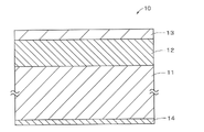
- FIG. 1 is a cross-sectional view showing the configuration of a magnetic recording medium according to a first embodiment
- FIG. 1 is a schematic diagram showing the configuration of a recording/reproducing device
- FIG. 10 is a cross-sectional view showing the configuration of a magnetic recording medium in a modified example
- 1 is an exploded perspective view showing an example of the configuration of a magnetic recording cartridge
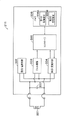
- FIG. 4 is a block diagram showing an example of the configuration of a cartridge memory
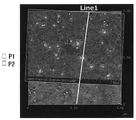
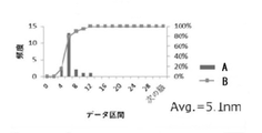
- FIG. FIG. 11 is an exploded perspective view showing an example of the configuration of a modification of the magnetic recording cartridge; It is an image which shows an example of the surface shape imaged by AFM. It is a figure which shows an example of the projection analysis result by AFM.
- FIG. 2 is a diagram showing an example of the shape of particles of magnetic powder; It is an example of a TEM photograph of a sample cross section. It is another example of a TEM photograph of a cross section of a sample.
- FIG. 2 is a diagram showing an example of a sample mount used for measuring the extraction rate of fatty acid or fatty acid ester.
- the measurement shall be performed in an environment of 25°C ⁇ 2°C and 50% RH ⁇ 5% RH.
- the present inventors have found that by adjusting the extraction rate of the fatty acid or fatty acid ester contained in the magnetic recording medium as a lubricant described below and by adjusting the height of the projections formed by the second particles, It has been found that an increase in frictional force can be prevented.
- a magnetic recording medium has a magnetic layer containing magnetic powder, and the magnetic layer contains first particles having conductivity and second particles having a Mohs hardness of 7 or more.
- the first particles may have electrical conductivity and function as a solid lubricant.
- the second particles have a Mohs hardness of 7 or more, preferably 9 or more, and can have a polishing effect and an anchoring effect.
- the first particles and the second particles form projections on the magnetic layer side surface.
- the method for measuring the average height (H 2 ) of the protrusions of the second particles is described in 2. below. (3) explains.
- the average height (H 2 ) of protrusions formed by the second particles is 7 nm or less, preferably 6.5 nm or less, more preferably 6.0 nm or less, and even more preferably 5.5 nm. Below, and more preferably below 5.3 nm.
- the lower limit of the average height (H 2 ) of the protrusions formed by the second particles is not particularly limited. Preferably, it may be 3.0 nm or more.
- a magnetic recording medium according to this technology contains a fatty acid.
- the magnetic recording medium according to the present technology may further include a fatty acid ester. Such fatty acid or fatty acid ester bleeds onto the surface of the magnetic recording medium and coats the surface of the second particles with the fatty acid or fatty acid ester, thereby reducing damage to the magnetic head.
- the fatty acid or fatty acid ester is contained in the non-magnetic layer (underlayer) and magnetic layer.
- Fatty acids are usually trapped in magnetic powder or non-magnetic powder and hardly seep out onto the surface of the magnetic recording medium.
- the extraction rate of the fatty acid or fatty acid ester is used as an index of how easily the fatty acid or fatty acid ester oozes out from the surface of the magnetic recording medium. That is, a large extraction rate value means that the fatty acid or fatty acid ester is less likely to be captured by the magnetic powder or the like and is likely to exude, and a small extraction rate means that the fatty acid or fatty acid ester magnetic powder It means that the degree of capture by such as is large and it is difficult to seep out.
- the following method may be adopted in order to improve the extraction rate of fatty acid or fatty acid ester.
- a coating agent Organic acids having one or more polar groups such as carboxylic acid, phosphonic acid, and sulfonic acid, and metals thereof A method of coating the surface of a magnetic powder or a non-magnetic powder with a coating agent that functions as an acid group, such as a salt.
- a coupling agent silane, aluminum, titanium, etc.
- the fatty acid extraction rate defined by the following formula may be 45% or higher, preferably 50% or higher, more preferably 55% or higher, and even more preferably 60% or higher. If the fatty acid extraction rate is less than 45%, the friction increases, the magnetic head deteriorates due to frictional heat and electrification, the damage to the coating film increases, the powder falling off increases, and the durability deteriorates. do.
- Fatty acid extraction rate (%) [5-minute fatty acid extraction amount (mg/m 2 )/total fatty acid extraction amount (mg/m 2 )] ⁇ 100
- the upper limit of the extraction rate of the fatty acid is not particularly limited, but from the viewpoint of suppressing the plasticization of the coating film itself, increased powder falloff, and deterioration of durability, it is preferably 75%. or less, more preferably 73% or less, and even more preferably 70% or less.
- the method for measuring the extraction rate of fatty acids is described in 2. below. (3) explains.
- the 5-minute extraction amount (mg/m 2 ) of the fatty acid is preferably 3.0 mg/m 2 or more, more preferably 3.5 mg/m 2 or more, still more preferably 4.0 mg/m 2 or more, and still more preferably 4.0 mg/m 2 or more. Preferably, it may be 4.5 mg/m 2 or more.
- the upper limit of the 5-minute extraction amount of the fatty acid is not particularly limited, but is preferably 14.0 mg/m 2 or less, more preferably 13.0 mg/m 2 or less, and still more preferably 12.0 mg/m 2 or less. m 2 or less, even more preferably 10.0 mg/m 2 or less.
- the method for measuring the 5-minute extraction amount of fatty acids is described in 2. below. (3) explains.
- the total extraction amount (mg/m 2 ) of the fatty acid is preferably 5.0 mg/m 2 or more, more preferably 7.0 mg/m 2 or more, still more preferably 9.0 mg/m 2 or more, and even more preferably can be greater than or equal to 10.0 mg/m 2 .
- the upper limit of the total extraction amount of the fatty acid is not particularly limited, but is preferably 16.0 mg/m 2 or less, more preferably 15.0 mg/m 2 or less, still more preferably 14.0 mg/m 2 or less. 2 or less, and even more preferably 13.0 mg/m 2 or less.
- the method for measuring the total amount of fatty acid extracted is described in 2. below. (3) explains.
- the magnetic recording medium according to the present technology further contains a fatty acid ester, which increases friction, degrades the magnetic head due to frictional heat and electrification, increases damage to the coating film, increases powder falling off, and further improves durability.
- the extraction rate of the fatty acid ester defined by the following formula is preferably 60% or more, more preferably 65% or more, still more preferably 70% or more, and still more preferably 75% or more.
- Fatty acid ester extraction rate (%) [5-minute extraction amount of fatty acid ester (mg/m 2 )/total extraction amount of fatty acid ester (mg/m 2 )] ⁇ 100
- the upper limit of the extraction rate of the fatty acid ester is not particularly limited, but from the viewpoint of suppressing the plasticization of the coating film itself, the increase in powder falling, and the deterioration in durability, it is preferably 90. % or less, more preferably 85% or less, and even more preferably 80% or less.
- the method for measuring the extraction rate of fatty acid ester is described in 2. below. (3) explains.
- the 5-minute extraction amount (mg/m 2 ) of the fatty acid ester is preferably 10.0 mg/m 2 or more, more preferably 12.0 mg/m 2 or more, still more preferably 14.0 mg/m 2 or more, and further preferably 14.0 mg/m 2 or more. More preferably, it may be 16.0 mg/m 2 or more.
- the upper limit of the 5-minute extraction amount of the fatty acid ester is not particularly limited, but if it exceeds 25.0 mg/m 2 , the plasticization of the coating progresses, and there is a possibility that powder falling off will worsen. , preferably 20.0 mg/m 2 or less, more preferably 19.0 mg/m 2 or less, still more preferably 18.0 mg/m 2 or less, and even more preferably 17.0 mg/m 2 or less.
- the method for measuring the amount of fatty acid ester extracted for 5 minutes is described in 2 below. (3) explains.
- the total extraction amount (mg/m 2 ) of the fatty acid ester is preferably 12.0 mg/m 2 or more, more preferably 14.0 mg/m 2 or more, still more preferably 16.0 mg/m 2 or more, and still more preferably 16.0 mg/m 2 or more. Preferably, it may be 19.0 mg/m 2 or more.
- the upper limit of the total extraction amount of the fatty acid ester is not particularly limited, but is preferably 25.0 mg/m 2 or less, more preferably 24.0 mg/m 2 or less, and still more preferably 23.0 mg/m 2 or less. m 2 or less, even more preferably 22.0 mg/m 2 or less.
- the method for measuring the total extraction amount of fatty acid ester is described in 2. below. (3) explains.
- a magnetic recording medium according to the present technology is preferably a long magnetic recording medium, and can be, for example, a magnetic recording tape (particularly a long magnetic recording tape).
- a magnetic recording medium may include a magnetic layer, a nonmagnetic layer (underlayer), a base layer, and a back layer in this order, and may include other layers in addition to these layers.
- the other layer may be appropriately selected according to the type of magnetic recording medium.
- the magnetic recording medium is a coating type magnetic recording medium. For layers included in the magnetic recording medium other than the above four layers, refer to these descriptions.
- the average thickness (average total thickness) tT of the magnetic recording medium according to the present technology is, for example, preferably 5.7 ⁇ m or less, 5.6 ⁇ m or less, 5.5 ⁇ m or less, 5.4 ⁇ m or less, 5.3 ⁇ m or less, more preferably It may be 5.2 ⁇ m or less, 5.0 ⁇ m or less, more preferably 4.6 ⁇ m or less, still more preferably 4.4 ⁇ m or less. Since the magnetic recording medium is so thin, it is possible, for example, to increase the tape length wound up in one magnetic recording cartridge, thereby increasing the recording capacity per magnetic recording cartridge. can be done.
- the lower limit of the average thickness (average total thickness) tT of the magnetic recording medium is not particularly limited, it is, for example, 3.5 ⁇ m ⁇ tT .
- the average thickness tm of the magnetic layer of the magnetic recording medium according to the present technology is preferably 0.08 ⁇ m or less, more preferably 0.07 ⁇ m or less, even more preferably 0.06 ⁇ m or less, 0.05 ⁇ m or less, and even more preferably 0.05 ⁇ m or less. 04 ⁇ m or less.
- the lower limit of the average thickness tm of the magnetic layer is not particularly limited, it may preferably be 0.03 ⁇ m or more.
- the method for measuring the average thickness of the magnetic layer is described in 2. below. (3) explains.
- the average thickness of the non-magnetic layer (average thickness of the underlayer) of the magnetic recording medium according to the present technology is preferably 1.2 ⁇ m or less, more preferably 1.0 ⁇ m or less, 0.9 ⁇ m or less, or 0.8 ⁇ m or less, or 0 0.7 ⁇ m or less, more preferably 0.6 ⁇ m or less.
- the lower limit of the average thickness of the non-magnetic layer is not particularly limited, but is preferably 0.2 ⁇ m or more, more preferably 0.3 ⁇ m or more.
- the method for measuring the average thickness of the non-magnetic layer is described in 2. below. (3) explains.
- the average thickness of the base layer of the magnetic recording medium according to the present technology can be preferably 4.5 ⁇ m or less, more preferably 4.2 ⁇ m or less, 4.0 ⁇ m or less, 3.6 ⁇ m or less, and even more preferably 3.0 ⁇ m or less.
- the method for measuring the average thickness of the base layer is described in 2. below. (3) explains.
- the average thickness of the back layer of the magnetic recording medium according to the present technology can be preferably 0.6 ⁇ m or less, more preferably 0.5 ⁇ m or less, even more preferably 0.4 ⁇ m or less, 0.3 ⁇ m or less, or 0.25 ⁇ m or less. .
- the method for measuring the average thickness of the back layer is described in 2. below. (3) explains.
- the average particle volume of the magnetic powder contained in the magnetic recording medium of the present technology may be 2600 nm 3 or less, preferably 2000 nm 3 or less, and more preferably 1600 nm 3 or less. By having the average particle volume within the above numerical range, the electromagnetic conversion characteristics are improved. Although the magnetic powder contained in the magnetic recording medium of the present technology has such a very small average particle volume, the magnetic recording medium of the present technology has excellent thermal stability as described above. Although it is difficult to achieve both electromagnetic conversion characteristics and thermal stability, the present technology can improve both electromagnetic conversion characteristics and thermal stability.
- the average particle volume of the magnetic powder may be, for example, 500 nm 3 or more, especially 700 nm 3 or more. The method for measuring the average particle volume of the magnetic powder is described in 2. below. (3) explains.
- the squareness ratio in the vertical direction is preferably 65% or more, more preferably 67% or more, and even more preferably 70% or more.
- the perpendicular orientation of the magnetic powder is sufficiently high, so that a better cNR can be obtained. Therefore, better electromagnetic conversion characteristics can be obtained.
- the method for measuring the squareness ratio in the vertical direction is described in 2 below. (3) explains.
- a magnetic recording medium consistent with the present technology may have, for example, at least one data band and at least two servo bands.
- the number of data bands can be, for example, 2-10, especially 3-6, more especially 4 or 5.
- the number of servo bands can be, for example, 3-11, especially 4-7, more especially 5 or 6.
- These servo bands and data bands may be arranged, for example, so as to extend in the longitudinal direction of an elongated magnetic recording medium (particularly a magnetic recording tape), in particular substantially parallel.
- the data band and the servo band may be provided on the magnetic layer.
- a magnetic recording medium having data bands and servo bands in this way a magnetic recording tape conforming to the LTO (Linear Tape-Open) standard can be mentioned.
- a magnetic recording medium according to the present technology may be a magnetic recording tape according to the LTO standard.
- a magnetic recording medium consistent with the present technology may be a magnetic recording tape conforming to LTO8 or later standards (eg, LTO9, LTO10, LTO11, LTO12, etc.).
- the width of the elongated magnetic recording medium (especially magnetic recording tape) according to the present technology is, for example, 5 mm to 30 mm, particularly 7 mm to 25 mm, more particularly 10 mm to 20 mm, and even more particularly 11 mm to It can be 19 mm.
- the length of the elongated magnetic recording medium (especially magnetic recording tape) can be, for example, 500m to 1500m.
- the tape width according to the LTO8 standard is 12.65 mm and the length is 960 m.
- the magnetic recording medium 10 is, for example, a perpendicularly oriented magnetic recording medium, and as shown in FIG.
- the surface on which the magnetic layer 13 is provided is referred to as the magnetic surface
- the surface opposite to the magnetic surface (the surface on which the back layer 14 is provided) is referred to as the magnetic surface. ) is called the back surface.
- the magnetic recording medium 10 has a long shape, and runs in the longitudinal direction during recording and reproduction.
- the magnetic recording medium 10 may be configured to record signals at the shortest recording wavelength of preferably 100 nm or less, more preferably 75 nm or less, even more preferably 60 nm or less, and particularly preferably 50 nm or less. It can be used in a recording/reproducing device whose wavelength is within the above range.
- This recording/reproducing apparatus may have a ring-type head as a recording head.
- the recording track width is, for example, 2 ⁇ m or less.
- the base layer 11 can function as a support for the magnetic recording medium 10, and can be, for example, a flexible elongated non-magnetic substrate, particularly a non-magnetic film.
- the average thickness of the base layer 11 is, for example, preferably 4.5 ⁇ m or less, more preferably 4.2 ⁇ m or less, and can be 4.0 ⁇ m or less, 3.6 ⁇ m or less, further preferably 3.0 ⁇ m or less.
- the lower limit of the average thickness of the base layer 11 may be determined, for example, from the viewpoint of the film production limit of the film or the function of the base layer 11 .
- the base layer 11 may include, for example, at least one of polyester-based resin, polyolefin-based resin, cellulose derivative, vinyl-based resin, aromatic polyetherketone resin, and other polymer resins.
- the base layer 11 contains two or more of the above materials, the two or more materials may be mixed, copolymerized, or laminated.
- the polyester resin for example, PET (polyethylene terephthalate), PEN (polyethylene naphthalate), PBT (polybutylene terephthalate), PBN (polybutylene naphthalate), PCT (polycyclohexylene dimethylene terephthalate), PEB (polyethylene- p-oxybenzoate), and polyethylene bisphenoxycarboxylate, or a mixture of two or more.
- the base layer 11 may be formed from PET or PEN.
- the polyolefin resin may be, for example, one or a mixture of two or more of PE (polyethylene) and PP (polypropylene).
- the cellulose derivative may be, for example, one or a mixture of two or more of cellulose diacetate, cellulose triacetate, CAB (cellulose acetate butyrate), and CAP (cellulose acetate propionate).
- the vinyl resin may be, for example, one or a mixture of two or more of PVC (polyvinyl chloride) and PVDC (polyvinylidene chloride).
- the aromatic polyether ketone resin is, for example, one or two of PEK (polyether ketone), PEEK (polyether ether ketone), PEKK (polyether ketone ketone), and PEEKK (polyether ether ketone ketone) It may be a mixture of more than one species.
- base layer 11 may be formed from PEEK.
- PA polyamide, nylon
- aromatic PA aromatic polyamide, aramid
- PI polyimide
- aromatic PI aromatic polyimide
- PAI polyamideimide
- aromatic PAI aromatic polyamideimide
- PBO polybenzoxazole, e.g. Zylon®, polyether, polyetherester, PES (polyethersulfone), PEI (polyetherimide), PSF (polysulfone), PPS (polyphenylene sulfide), PC (polycarbonate), PAR (polyarylate), and PU (polyurethane), or a mixture of two or more thereof.
- the magnetic layer 13 can be, for example, a perpendicular recording layer.
- the magnetic layer 13 contains magnetic powder.
- the magnetic layer 13 contains, in addition to magnetic powder, conductive first particles and second particles having a Mohs hardness of 7 or more.
- the magnetic layer 13 may further contain, for example, a binder.
- the magnetic layer 13 may further contain additives such as lubricants and antirust agents, if necessary.
- the average thickness t m of the magnetic layer 13 is preferably 0.08 ⁇ m or less, more preferably 0.07 ⁇ m or less, and even more preferably 0.06 ⁇ m or less, 0.05 ⁇ m or less, or 0.04 ⁇ m or less.
- the lower limit of the average thickness t m of the magnetic layer 13 is not particularly limited, it may preferably be 0.03 ⁇ m or more. The fact that the average thickness tm of the magnetic layer 13 is within the above numerical range contributes to the improvement of the electromagnetic conversion characteristics.
- the magnetic layer 13 is preferably a vertically oriented magnetic layer.
- perpendicular orientation means that the squareness ratio S1 measured in the longitudinal direction (running direction) of the magnetic recording medium 10 is 35% or less.
- the magnetic layer 13 may be an in-plane oriented (longitudinal) magnetic layer. That is, the magnetic recording medium 10 may be a horizontal recording type magnetic recording medium. However, vertical orientation is more preferable in terms of high recording density.
- Examples of magnetic particles forming the magnetic powder contained in the magnetic layer 13 include epsilon-type iron oxide ( ⁇ iron oxide), gamma hematite, magnetite, chromium dioxide, cobalt-coated iron oxide, hexagonal ferrite, barium ferrite (BaFe), Co ferrite, strontium ferrite, and metals may include, but are not limited to.
- the magnetic powder may be one of these, or may be a combination of two or more.
- the magnetic powder may include ⁇ -iron oxide magnetic powder, barium ferrite magnetic powder, cobalt ferrite magnetic powder, or strontium ferrite magnetic powder.
- the ⁇ -iron oxide may contain Ga and/or Al.
- the average particle size (average maximum particle size) D of the magnetic powder is preferably 22 nm or less, more preferably 8 nm or more and 22 nm or less, and even more preferably 10 nm or more and 20 nm or less.
- the average particle size D of the magnetic powder is determined as follows. First, the magnetic recording medium 10 to be measured is processed by FIB (Focused Ion Beam) method or the like to prepare a thin piece, and the cross section of the thin piece is observed by TEM. Next, 500 ⁇ -iron oxide particles are randomly selected from the TEM photograph taken, and the maximum particle size d max of each particle is measured to determine the particle size distribution of the maximum particle size d max of the magnetic powder.
- the “maximum particle size d max ” means the so-called maximum Feret diameter, specifically, the distance between two parallel lines drawn from all angles so as to touch the contour of the ⁇ -iron oxide particle. means the largest of Thereafter, the median diameter (50% diameter, D50) of the maximum particle size d max is determined from the particle size distribution of the maximum particle size d max , and this is defined as the average particle size (average maximum particle size) D of the magnetic powder.
- the shape of the magnetic powder is preferably plate-like, spherical, or rectangular.
- the shape of the magnetic powder depends on the crystal structure of the magnetic particles.
- Plate-shaped magnetic powders include, for example, BaFe and strontium ferrite having a hexagonal plate-like shape.
- Magnetic powders having a spherical shape include, for example, ⁇ -iron oxide.
- Magnetic powder having a rectangular shape includes, for example, cobalt ferrite having a cubic shape.
- the magnetic powder may preferably contain a powder of nanoparticles containing ⁇ -iron oxide (hereinafter referred to as " ⁇ -iron oxide particles").
- ⁇ -iron oxide particles can obtain a high coercive force even when they are fine particles.
- the ⁇ -iron oxide contained in the ⁇ -iron oxide particles is preferably crystal-oriented preferentially in the thickness direction (perpendicular direction) of the magnetic recording medium 10 .
- the ⁇ -iron oxide particles have a spherical or nearly spherical shape, or have a cubic or nearly cubic shape. Since the ⁇ -iron oxide particles have the above-described shape, the thickness of the medium using the ⁇ -iron oxide particles as the magnetic particles is reduced compared to the case where the hexagonal plate-shaped barium ferrite particles are used as the magnetic particles. It is possible to reduce the contact area between the particles in the direction and suppress the aggregation of the particles. Therefore, it is possible to improve the dispersibility of the magnetic powder and obtain a better SNR (Signal-to-Noise Ratio).
- ⁇ -iron oxide particles have a core-shell structure or Janus structure.
- the ⁇ -iron oxide particles are provided with a core portion and a two-layered shell portion provided around the core portion.
- the shell portion having a two-layer structure includes a first shell portion provided on the core portion and a second shell portion provided on the first shell portion.
- the capture of fatty acids may be suppressed by controlling the surface activity of the magnetic powder with the core-shell structure.
- the core portion contains ⁇ -iron oxide.
- the ⁇ -iron oxide contained in the core portion preferably has an ⁇ -Fe 2 O 3 crystal as a main phase, more preferably a single-phase ⁇ -Fe 2 O 3 .
- the first shell part covers at least part of the periphery of the core part.
- the first shell portion may partially cover the periphery of the core portion, or may cover the entire periphery of the core portion. From the viewpoint of ensuring sufficient exchange coupling between the core portion and the first shell portion and improving the magnetic properties, it is preferable that the entire surface of the core portion is covered.
- the first shell part is a so-called soft magnetic layer, and may contain a soft magnetic material such as ⁇ -Fe, Ni-Fe alloy or Fe-Si-Al alloy.
- ⁇ -Fe may be obtained by reducing ⁇ -iron oxide contained in the core.
- the second shell portion is an oxide film as an antioxidant layer.
- the second shell portion may comprise alpha iron oxide, aluminum oxide, or silicon oxide.
- Alpha-iron oxide can include, for example, at least one iron oxide of Fe 3 O 4 , Fe 2 O 3 , and FeO.
- the ⁇ -iron oxide may be obtained by oxidizing the ⁇ -Fe contained in the first shell.
- the ⁇ -iron oxide particles have the first shell portion as described above, thermal stability can be ensured.
- the coercive force Hc of the particles (core-shell type particles) as a whole can be adjusted to a coercive force Hc suitable for recording.
- the ⁇ -iron oxide particles have the second shell portion as described above, the ⁇ -iron oxide particles are exposed to the air during and before the manufacturing process of the magnetic recording medium 10, and the particle surfaces are rusted. and the like can be suppressed from deteriorating the properties of the ⁇ -iron oxide particles. Therefore, deterioration of the characteristics of the magnetic recording medium 10 can be suppressed.
- the ⁇ -iron oxide particles may have a shell portion with a single-layer structure.
- the shell portion has the same configuration as the first shell portion.
- the ⁇ -iron oxide particles may contain an additive instead of a core-shell structure, or may have a core-shell structure and contain an additive. In these cases, some of the Fe in the ⁇ -iron oxide particles is replaced by the additive. Since the ⁇ -iron oxide particles contain an additive, the coercive force Hc of the entire ⁇ -iron oxide particles can be adjusted to a coercive force Hc suitable for recording, so that the ease of recording can be improved.
- the additive is a metal element other than iron, preferably a trivalent metal element, more preferably one or more selected from the group consisting of aluminum (Al), gallium (Ga), and indium (In).
- the ⁇ -iron oxide containing the additive is an ⁇ -Fe 2-x M x O 3 crystal (here, M is a metal element other than iron, preferably a trivalent metal element, more preferably Al , Ga, and In, where x satisfies, for example, 0 ⁇ x ⁇ 1.
- the magnetic powder may be barium ferrite (BaFe) magnetic powder.
- the barium ferrite magnetic powder contains iron oxide magnetic particles having barium ferrite as the main phase (hereinafter referred to as "barium ferrite particles").
- Barium ferrite magnetic powder has high data recording reliability, for example, its coercive force does not decrease even in a hot and humid environment. From this point of view, barium ferrite magnetic powder is preferable as the magnetic powder.
- the average particle size of the barium ferrite magnetic powder can be 50 nm or less, more preferably 10 nm or more and 40 nm or less, and even more preferably 12 nm or more and 25 nm or less.
- the average thickness t m [nm] of the magnetic layer 13 is preferably 0.08 ⁇ m or less, more preferably 0.07 ⁇ m or less, and even more preferably 0.06 ⁇ m or less.
- the coercive force Hc measured in the thickness direction (perpendicular direction) of the magnetic recording medium 10 is preferably 160 kA/m or more and 280 kA/m or less, more preferably 165 kA/m or more and 275 kA/m or less, and even more preferably 170 kA/m. m or more and 270 kA/m or less.
- the magnetic powder can be cobalt ferrite magnetic powder.
- Cobalt ferrite magnetic powder contains iron oxide magnetic particles having cobalt ferrite as a main phase (hereinafter referred to as "cobalt ferrite magnetic particles").
- Cobalt ferrite magnetic particles preferably have uniaxial anisotropy.
- Cobalt ferrite magnetic particles for example, have a cubic or nearly cubic shape.
- Cobalt ferrite is cobalt ferrite containing Co.
- Cobalt ferrite may further contain, in addition to Co, one or more selected from the group consisting of Ni, Mn, Al, Cu, and Zn.
- Cobalt ferrite has, for example, an average composition represented by the following formula (1).
- CoxMyFe2Oz ( 1 ) M is, for example, one or more metals selected from the group consisting of Ni, Mn, Al, Cu, and Zn.
- x is 0.4 ⁇ x ⁇ 1.0
- y is a value within the range of 0 ⁇ y ⁇ 0.3, provided that x and y satisfy the relationship (x+y) ⁇ 1.0, z is 3 ⁇ z ⁇ It is a value within the range of 4.
- a part of Fe may be substituted with other metal elements.
- the average particle size of the cobalt ferrite magnetic powder is preferably 25 nm or less, more preferably 23 nm or less.
- the coercive force Hc of the cobalt ferrite magnetic powder is preferably 2500 Oe or more, more preferably 2600 Oe or more and 3500 Oe or less.
- the magnetic powder may include powder of nanoparticles containing hexagonal ferrite (hereinafter referred to as "hexagonal ferrite particles").
- Hexagonal ferrite particles have, for example, a hexagonal plate shape or a substantially hexagonal plate shape.
- the hexagonal ferrite may preferably contain at least one of Ba, Sr, Pb, and Ca, more preferably at least one of Ba and Sr.
- the hexagonal ferrite may in particular be barium ferrite or strontium ferrite, for example.
- Barium ferrite may further contain at least one of Sr, Pb, and Ca in addition to Ba.
- the strontium ferrite may further contain at least one of Ba, Pb, and Ca in addition to Sr. More specifically, hexagonal ferrite can have an average composition represented by the general formula MFe 12 O 19 .
- M is, for example, at least one of Ba, Sr, Pb and Ca, preferably at least one of Ba and Sr.
- M may be a combination of Ba and one or more metals selected from the group consisting of Sr, Pb and Ca.
- M may be a combination of Sr and one or more metals selected from the group consisting of Ba, Pb and Ca. Part of Fe in the above general formula may be substituted with another metal element.
- the average particle size of the magnetic powder may be preferably 50 nm or less, more preferably 10 nm or more and 40 nm or less, and even more preferably 15 nm or more and 30 nm or less.
- the first particles have conductivity.
- fine particles containing carbon as a main component can be used, and for example, carbon particles can be preferably used, and examples of such carbon particles include carbon black.
- carbon black for example, Asahi #15, #15HS manufactured by Asahi Carbon Co., Ltd. can be used.
- hybrid carbon in which carbon is attached to the surface of silica particles may be used.
- the second particles may have a Mohs hardness of 7 or more, preferably 7.5 or more, more preferably 8 or more, and even more preferably 8.5 or more, from the viewpoint of suppressing deformation due to contact with the magnetic head. From the viewpoint of suppressing head wear, the Mohs hardness of the second particles may preferably be 9.5 or less.
- the second particles may preferably be inorganic particles, such as ⁇ -Al 2 O 3 ( ⁇ -alumina), ⁇ -Al 2 O 3 ( ⁇ -alumina), ⁇ -Al having an ⁇ conversion rate of 90% or more.
- silicon carbide chromium oxide, cerium oxide, ⁇ -iron oxide, corundum, silicon nitride, titanium carbide, titanium oxide, silicon dioxide, tin oxide, magnesium oxide, tungsten oxide, zirconium oxide, Boron nitride, zinc oxide, calcium carbonate, calcium sulfate, barium sulfate, molybdenum disulfide, and magnetic iron oxide raw materials are dehydrated and annealed to obtain acicular ⁇ -iron oxide, optionally surface-treated with aluminum and/or silica. , diamond powder, and the like.
- the second particles are preferably alumina particles such as ⁇ -Al 2 O 3 ( ⁇ -alumina), ⁇ -Al 2 O 3 ( ⁇ -alumina), ⁇ -Al 2 O 3 ( ⁇ -alumina), and silicon carbide. be done. These second particles may have any shape such as acicular, spherical, or dice-like, but those having corners in a part of the shape are preferred because they have high abrilliance.
- the second particles form protrusions on the magnetic layer side surface.
- the average height (H 2 ) of protrusions formed by the second particles is 7 nm or less, preferably 6.5 nm or less, more preferably 6.0 nm or less, even more preferably 5.5 nm or less, and even more preferably 5. It can be 3 nm or less. Since the magnetic recording medium has an average height (H 2 ) of the protrusions formed by the second particles within the above numerical range, the spacing between the magnetic head and the magnetic recording medium can be reduced and It contributes to making it possible to maintain an appropriate polishing force for the magnetic head with little increase in friction due to running.
- the lower limit of the average height (H 2 ) of the protrusions formed by the second particles is not particularly limited. Preferably, it may be 3.0 nm or more.
- the magnetic layer 13 contains a lubricant.
- the lubricant may be one or more selected from fatty acids and fatty acid esters, and preferably contains both fatty acids and fatty acid esters.
- the fatty acid may preferably be a compound represented by the following general formula (1) or (2).
- the fatty acid may contain one or both of a compound represented by the following general formula (1) and a compound represented by general formula (2).
- the fatty acid ester may be preferably a compound represented by the following general formula (3) or (4).
- the fatty acid ester may contain one or both of a compound represented by the following general formula (3) and a compound represented by general formula (4).
- the lubricant is one or both of the compound represented by the general formula (1) and the compound represented by the general formula (2), and/or the compound represented by the general formula (3) and the compound represented by the general formula (4) By containing either one or both of the compounds shown, damage to the magnetic head can be prevented and reduction in output can be suppressed.
- fatty acids and fatty acid esters are as follows.
- Fatty acids include capric acid, lauric acid, myristic acid, palmitic acid, stearic acid, oleic acid, elaidic acid, linoleic acid, linolenic acid and the like.
- Fatty acid esters include butyl caprate, octyl caprylate, ethyl laurate, butyl laurate, octyl laurate, ethyl myristate, butyl myristate, octyl myristate, 2-ethylhexyl myristate, ethyl palmitate, and palmitic acid.
- the binder it is preferable to use a resin having a structure obtained by imparting a cross-linking reaction to a polyurethane-based resin or a vinyl chloride-based resin.
- the binder is not limited to these, and other resins may be blended as appropriate depending on the physical properties required for the magnetic recording medium 10 .
- the resin to be blended is not particularly limited as long as it is a resin commonly used in the coating type magnetic recording medium 10 .
- binder examples include polyvinyl chloride, polyvinyl acetate, vinyl chloride-vinyl acetate copolymer, vinyl chloride-vinylidene chloride copolymer, vinyl chloride-acrylonitrile copolymer, acrylic acid ester-acrylonitrile copolymer.
- acrylate-vinyl chloride-vinylidene chloride copolymer acrylate-vinylidene chloride copolymer, methacrylate-vinylidene chloride copolymer, methacrylate-vinyl chloride copolymer, methacrylate-ethylene copolymer
- Polymer polyvinyl fluoride, vinylidene chloride-acrylonitrile copolymer, acrylonitrile-butadiene copolymer, polyamide resin, polyvinyl butyral, cellulose derivatives (cellulose acetate butyrate, cellulose diacetate, cellulose triacetate, cellulose propionate, nitro cellulose), styrene-butadiene copolymers, polyester resins, amino resins, and synthetic rubbers.
- Thermosetting resins or reactive resins may be used as the binder, and examples thereof include phenol resins, epoxy resins, urea resins, melamine resins, alkyd resins, silicone resins, polyamine resins, and urea formaldehyde resin.
- polar functional groups such as —SO 3 M, —OSO 3 M, —COOM, and P ⁇ O(OM) 2 are introduced into each of the binders described above for the purpose of improving the dispersibility of the magnetic powder.
- M is a hydrogen atom or an alkali metal such as lithium, potassium, and sodium.
- the polar functional groups include side chain types having terminal groups of -NR1R2, -NR1R2R3 + X - , and main chain types of >NR1R2 + X - .
- R1, R2 and R3 are hydrogen atoms or hydrocarbon groups
- X- is a halogen element ion such as fluorine, chlorine, bromine or iodine, or an inorganic or organic ion.
- Polar functional groups also include -OH, -SH, -CN, and epoxy groups.
- the magnetic layer 13 contains nonmagnetic reinforcing particles such as aluminum oxide ( ⁇ , ⁇ , or ⁇ alumina), chromium oxide, silicon oxide, diamond, garnet, emery, boron nitride, titanium carbide, silicon carbide, titanium carbide, and titanium oxide. (rutile-type or anatase-type titanium oxide) and the like may be further contained.
- nonmagnetic reinforcing particles such as aluminum oxide ( ⁇ , ⁇ , or ⁇ alumina), chromium oxide, silicon oxide, diamond, garnet, emery, boron nitride, titanium carbide, silicon carbide, titanium carbide, and titanium oxide. (rutile-type or anatase-type titanium oxide) and the like may be further contained.
- the magnetic layer 13 may contain a coating agent to cover the surface of the magnetic powder.
- coating agents include organic acids having one or more polar groups such as carboxylic acid, phosphonic acid, and sulfonic acid, those that function as acid groups such as metal salts thereof, and coupling agents (silane, aluminum, titanium, etc.). ), carbon, metal oxides, hydroxides (aluminum, yttrium, etc.).
- Organic acids include acetic acid, oxalic acid, citric acid, malonic acid, succinic acid, glutaric acid, adipic acid, phthalic acid, isophthalic acid, terephthalic acid, benzoic acid, toluic acid, p-hydroxybenzoic acid, naphthoic acid, and naphthalene dicarboxylic acid.
- the non-magnetic layer (underlayer) 12 is a non-magnetic layer containing non-magnetic powder and a binder as main components.
- the above description of the binder contained in the magnetic layer 13 also applies to the binder contained in the non-magnetic layer 12 .
- the non-magnetic layer 12 may further contain at least one additive selected from first particles, lubricants, hardeners, rust inhibitors, and the like, if necessary.
- the average thickness of the nonmagnetic layer 12 is preferably 1.2 ⁇ m or less, more preferably 1.0 ⁇ m or less, 0.9 ⁇ m or less, or 0.8 ⁇ m or less, or 0.7 ⁇ m or less, and even more preferably 0.6 ⁇ m or less. sell.
- the lower limit of the average thickness of the non-magnetic layer 12 is not particularly limited, it is preferably 0.2 ⁇ m or more, more preferably 0.3 ⁇ m or more.
- the non-magnetic powder contained in the non-magnetic layer 12 can contain, for example, at least one selected from inorganic particles and organic particles.
- One type of non-magnetic powder may be used alone, or two or more types of non-magnetic powder may be used in combination.
- Inorganic particles include, for example, one or a combination of two or more selected from metals, metal oxides, metal carbonates, metal sulfates, metal nitrides, metal carbides, and metal sulfides. More specifically, the inorganic particles can be, for example, one or more selected from iron oxyhydroxide, hematite, titanium oxide, and carbon black.
- Examples of the shape of the non-magnetic powder include various shapes such as acicular, spherical, cubic, and plate-like, but are not particularly limited to these.
- the non-magnetic layer 12 may contain a coating agent to cover the surface of the non-magnetic powder.
- Such coating agents may be the same as those contained in the magnetic layer 13 . Therefore, description of the coating is omitted.
- the back layer 14 may contain a binder and non-magnetic powder.
- the back layer 14 may contain various additives such as lubricants, curing agents, antistatic agents and organic acids, if necessary.
- lubricants such as lubricants, curing agents, antistatic agents and organic acids, if necessary.
- the average particle size of the inorganic particles contained in the back layer 14 is preferably 10 nm or more and 150 nm or less, more preferably 15 nm or more and 110 nm or less.
- the average particle size of the inorganic particles is determined in the same manner as the average particle size D of the magnetic powder.
- the average thickness tb of the back layer 14 is preferably 0.6 ⁇ m or less, more preferably 0.5 ⁇ m or less, and still more preferably 0.4 ⁇ m or less, 0.3 ⁇ m or less, 0.25 ⁇ m or less, or 0.2 ⁇ m or less. sell. Since the average thickness t b of the back layer 14 is within the above range, even when the average thickness (average total thickness) t T of the magnetic recording medium 10 is t T ⁇ 5.7 ⁇ m, the non-magnetic layer 12 and the base layer The average thickness of the magnetic recording medium 11 can be kept thick, so that the running stability of the magnetic recording medium 10 in the recording/reproducing apparatus can be maintained.
- FIG. 18 is a diagram showing an example of a sample mount used for extraction rate measurement. An inverted triangle mark is marked 50 cm in the middle of the graph paper as shown in FIG. Place the graph paper parallel to the desk and fix both ends of the graph paper with double-sided tape. Attach double-sided tape so that it covers the two 1m mark lines and set the sample mount.
- Standard Reagent The type of standard reagent varies depending on the fatty acid or fatty acid ester used. Also, the concentration is arbitrary. As an example, the case of using stearic acid as the fatty acid and butyl stearate as the fatty acid ester is shown.
- a standard reagent for butyl stearate is prepared as follows.
- a stearic acid standard reagent (manufactured by Junsei Chemical, purity 95.0%) is prepared.
- a standard reagent of butyl stearate (manufactured by Junsei Chemical, purity 95.0%) is prepared.
- ⁇ Standard reagent preparation> Place the prepared standard reagent in an ultrasonic cleaner for 15 minutes. After the sonication is completed, insert the filter-set syringe into the vial and pour the standard reagent directly into the syringe. Fill standard reagents into vials. Push the center shaft to push the liquid into the vial bottle. Once the vial is about the shoulder level, close the aluminum lid. The standard reagent remaining in the syringe is passed through the filter and returned to the screw vial.
- the magnetic tape T accommodated in the cartridge 10A is unwound, and the magnetic tape T is cut into a length of about 5 m at a position 20 m in the longitudinal direction from the joint of the magnetic tape T and the leader tape LT.
- the magnetic tape is stuck to the double-sided tape of the sample mount while alternately stacking Mag/Back in parallel. Be careful not to apply too much tension when attaching the magnetic tape.
- the P/C surface layer is discarded, and five 1 m x 5 magnetic tapes are collected. Place a ruler along the 1m mark on the sample mount, and cut 1m of the magnetic tape with a cutter.
- A. 5 minute extraction Weigh 60 ml hexane into a 100 ml graduated cylinder. Set the stopwatch for 5 minutes. A 120 ml screw tube containing a sample is placed in an automatic shaker set at 25° C., and the aluminum lid is left open. Put 60 ml of weighed hexane into a 120 ml round-bottomed flask, cover with an aluminum lid, turn on the power of the stopwatch and the automatic shaker at the same time to start shaking (set the rotation speed of the automatic shaker to 300 rpm). ). After 5 minutes from the start of shaking, 50 ml of the sample is weighed and transferred to a 100 ml graduated cylinder. Transfer the sample in the graduated cylinder to the eggplant flask.
- hexane is removed from the sample in the 110 ml screw tube using an evaporator in the same manner as the 5 minute extraction. After that, add 5 ml of a mixed solvent of acetonitrile and ultrapure water (if the concentration is too high and the HPLC peak area is shaken off, use 10 ml) to the sample in the eggplant flask. Make a substitution and take a measurement.
- the height of the projection formed by the second particles was determined by shape analysis using an atomic force microscope (hereinafter referred to as AFM) and field emission scanning electron microscope (hereinafter FE) for the same portion of the measurement sample.
- AFM atomic force microscope
- FE field emission scanning electron microscope
- -SEM from the FE-SEM image captured by image analysis using the brightness difference due to the difference in the secondary electron emission amount of each of the first particle and the second particle. be done.
- the AFM makes it possible to measure the height of the protrusions
- the FE-SEM makes it possible to identify whether each protrusion is formed by the first particle or the second particle.
- the image obtained by the AFM for the same location and the image obtained by the FE-SEM for the certain region are superimposed to obtain a composite image, and from the obtained composite image, the particles forming each protrusion (whether it is a first particle or a second particle) can be associated with the height of each protrusion.
- a method for measuring the height of protrusions using AFM, a method for identifying the type of particles forming protrusions using FE-SEM, and a method for associating the height of protrusions with the types of particles forming protrusions are described below.
- the height of the projections formed by the second particles is obtained as follows. First, from the magnetic recording medium 10 in the user data area (24 m or more from the leader pin) in the LTO cartridge, a size that fits on the sample table for SEM observation is cut out to prepare a measurement sample. Next, the surface of the measurement sample is marked, avoiding the central portion of the measurement sample. Examples of the marking method include a method of forming linear or point-like depressions on the magnetic recording medium 10 with a manipulator, a nine-denter, or the like, and a method of forming protrusions on the magnetic recording medium 10 with silver paste or the like. .
- the tip of the probe may become dirty and an accurate shape image may not be obtained. is preferred.
- the shape of the marking portion on the surface of the measurement sample is analyzed by AFM. Since the marked portion is recessed, the measurement is performed with an AFM at a viewing angle of 5 ⁇ m ⁇ 5 ⁇ m so that the marked portion is positioned as close to the edge of the field of view as possible. Protrusions around the marking portion shall not be measured. Next, measurement is performed at a viewing angle of 10 ⁇ m ⁇ 10 ⁇ m to determine a mark portion, and a portion without marking is measured at a viewing angle of 5 ⁇ m ⁇ 5 ⁇ m in alignment with the mark portion.
- the measurement conditions for the shape analysis are as described below.
- the second particles if 20 or more particles can be identified from one measurement sample in one field of view of AFM, one field of view is measured by AFM.
- the second particles if less than 20 particles can be identified in one field of view of the AFM, multiple (eg, 3-5) fields of view are measured from one measurement sample.
- 20 points identified as particles are secured by binarization processing, the 20 measured values by AFM are averaged, and the obtained average value is used as the height of the projection.
- FIG. 7 is an example of an image showing an example of a surface shape captured by AFM.
- FIG. 8 is a diagram showing an example of a projection analysis result by AFM.
- FIG. 9 is a diagram showing an example of height distribution of protrusions. Data such as the number of protrusions formed and the height of protrusions formed by the particles can be obtained from the obtained information.
- FIG. 10A is an example of an FE-SEM image. From the obtained FE-SEM image, it is possible to identify the type of particles forming the protrusions by using the luminance difference due to the difference in the amount of secondary electron emission between the first particles and the second particles. Image processing for the identification will be described later. Also, the position of the protrusion formed by each of the first particles and the second particles in the FE-SEM image is identified.
- the obtained FE-SEM image (Fig. A in Fig. 10) is binarized using the image processing software Image J under each of the two processing conditions described below.
- Information on the number of projections formed by each of the first particles and the second particles, the average area per projection, the total area of the projections, and the diameter of the projections (Feret diameter) from the image obtained by the binarization process. is obtained.
- the second particles with high brightness (white areas in Figure A in FIG. 10) and the first particles with low brightness (black areas in Figure A in FIG. 10) are subjected to the following conditions. to change
- B diagram in FIG. 10 is a second particle (alumina particle) formed by binarizing the FE-SEM image of A diagram in FIG. 10 under the binarization processing conditions of the second particle (alumina particle). It is an image showing the positional distribution of protrusions. The following information about the second particles was obtained from the obtained image.
- C diagram in FIG. 10 is formed by the first particles (carbon black particles) obtained by binarizing the FE-SEM image of A diagram in FIG. 10 under the binarization processing conditions of the first particles (carbon black particles).
- 10 is an image showing the positional distribution of the projections formed. The following information regarding the first particles was obtained from the obtained image.
- FIG. 11 is a composite image in which the AFM image ( Figure B) and the FE-SEM image ( Figure A) are superimposed so that the positions of the corresponding protrusions match.
- FIG. 11 the positions of the protrusions formed by the first particles P1 and the protrusions formed by the second particles P2, which are present in the FE-SEM image (Fig.
- each position is marked differently so that the positions of the protrusions can be distinguished from each other.
- the position of the protrusion formed by the first particle (carbon black particle) P1 and the second particle (alumina particle) determined by the binarization process, which are present in the AFM image (Fig. B) before image synthesis. ) are marked differently at each location so that they can be distinguished from the location of the protrusion formed by P2. From the composite image in which the AFM image (Fig. B) and the FE-SEM image (Fig. A) are superimposed so that the positions of the corresponding projections are aligned, each projection is the first particle P1 or the second particle P2. It is determined from which particles it is formed.
- the marked portion was measured with an AFM at a viewing angle of 10 ⁇ m ⁇ 10 ⁇ m, and then the portion without markings was measured at a viewing angle of 5 ⁇ m ⁇ 5 ⁇ m. does not exist in
- FIG. 12 is an enlarged view of a composite image obtained by superimposing an AFM image and an FE-SEM image.
- FIG. 13 is a diagram showing the analysis results (projection height measurement results) by AFM for line 1 (Line 1) set at an arbitrary position in FIG. As shown in FIG. 13, the height of the protrusions formed by the second particles (alumina particles) present on line 1 can be identified. In this way, the height of the protrusion is specified from the combined image and the AFM analysis result.
- the average height of the protrusions formed by the second particles is determined.
- the average height of the protrusions can be obtained, for example, from the cumulative frequency distribution of protrusions formed by the second particles.
- FIG. 14 is a diagram showing a cumulative frequency distribution of heights of protrusions formed by second particles (alumina particles).
- A indicates frequency and B indicates cumulative %.
- FIG. 14 shows that the average height of protrusions formed by the second particles (alumina particles) is 5.1 nm.
- a so-called full-volume test (full-length full-surface running test) is performed by recording and reproducing data on the entire surface of the magnetic tape. After that, the magnetic head of the drive is observed with an optical microscope to confirm whether or not the constituent material of the magnetic layer adheres to the magnetic head. Next, the adherence of the constituent material of the magnetic layer to the magnetic head after running over the entire length is evaluated according to the following three-stage criteria.
- [standard] Good Adhesion of the constituent material of the magnetic layer to the head is not observed.
- ⁇ Adhesion of the constituent material of the magnetic layer was observed only on the end portion where the tape edge runs on the tape running surface of the head.
- x Adhesion of the constituent material of the magnetic layer was observed anywhere on the tape running surface of the head. If the evaluation result is " ⁇ " or " ⁇ ”, there is no problem with the reliability of the magnetic tape. If the evaluation result is "x”, head clogging occurs for a short time, and the total capacity of the cartridge becomes insufficient.
- Output degradation due to magnetic head damage is evaluated according to the following procedure. (1) Measure the drive output (2T, 8T) and head resistance before evaluation. (2) Start the test under the ambient environment. Full-length recording on the entire surface is performed with one roll, and when the recording is completed, the cartridge is replaced with a new one. (3) Measure the drive output and the head resistance every 25 windings to confirm the output change and the head resistance change. Based on the drive output before evaluation, the degree of deterioration (dB) is confirmed. (4) Repeat the above operation (3) up to 50 rolls. Next, drive output deterioration after running 50 rolls is evaluated according to the following four-stage criteria.
- the upper limit of the average thickness (average total thickness) tT of the magnetic tape T is preferably 5.7 ⁇ m or less, 5.2 ⁇ m or less, more preferably 5.0 ⁇ m or less, even more preferably 4.6 ⁇ m or less, and particularly preferably It is 4.4 ⁇ m or less.
- the average thickness t T of the magnetic tape T is 5.2 ⁇ m or less, the recording capacity that can be recorded in one data cartridge can be increased compared to general magnetic tapes.
- the lower limit of the average thickness tT of the magnetic tape T is not particularly limited, it is, for example, 3.5 ⁇ m or more.
- the average thickness tT of the magnetic tape T is obtained as follows. First, the magnetic tape T accommodated in the cartridge 10A is unwound, and a sample is prepared by cutting the magnetic tape T into a length of 250 mm at a position 30 m in the longitudinal direction from the joint between the magnetic tape T and the leader tape LT. Next, using a laser hologram (LGH-110C) manufactured by Mitutoyo as a measuring device, the thickness of the sample is measured at five positions, and the measured values are simply averaged (arithmetic average) to obtain an average thickness t T [ ⁇ m] is calculated. The five measurement positions are randomly selected from the samples so that they are different positions in the longitudinal direction of the magnetic tape T. As shown in FIG.
- the average thickness of the non-magnetic layer 12 is obtained as follows. First, the magnetic tape T accommodated in the cartridge 10A is unwound, and the magnetic tape T is stretched to a length of 250 mm at three positions of 10 m, 30 m, and 50 m in the longitudinal direction from the joint of the magnetic tape T and the leader tape LT. 3 samples are prepared. Subsequently, each sample is processed by the FIB method or the like to be thinned. When the FIB method is used, a carbon layer and a tungsten layer are formed as protective films as a pretreatment for observing a cross-sectional TEM image, which will be described later.
- the carbon layer is formed on the magnetic layer 13 side surface and the back layer 14 side surface of the magnetic tape T by vapor deposition, and the tungsten layer is further formed on the magnetic layer 13 side surface by vapor deposition or sputtering. be.
- the thinning is performed along the longitudinal direction of the magnetic tape T. As shown in FIG. That is, by the thinning, a cross section parallel to both the longitudinal direction and the thickness direction of the magnetic tape T is formed.
- TEM transmission electron microscope
- Apparatus TEM (H9000NAR manufactured by Hitachi, Ltd.) Accelerating voltage: 300 kV Magnification: 100,000 times
- the thickness of the non-magnetic layer 12 was measured at at least 10 positions in the longitudinal direction of the magnetic tape T, and the measured values were simply averaged ( Arithmetic mean) to obtain the average thickness ( ⁇ m) of the non-magnetic layer 12 .
- the average thickness of the base layer 11 is obtained as follows. First, the magnetic tape T accommodated in the magnetic recording cartridge 10A is unwound, and the magnetic tape T is cut into a length of 250 mm at a position 30 m in the longitudinal direction from the connection portion between the magnetic tape T and the leader tape LT to prepare a sample. do.
- the term “longitudinal direction” in the case of “longitudinal direction from the connection portion between the magnetic tape T and the leader tape LT” means the direction from one end on the side of the leader tape LT to the other end on the opposite side. do.
- the layers of the sample other than the base layer 11 are removed with a solvent such as MEK (methyl ethyl ketone) or dilute hydrochloric acid.
- a solvent such as MEK (methyl ethyl ketone) or dilute hydrochloric acid.
- the thickness of the sample (base layer 11) is measured at five positions, and the measured values are simply averaged (arithmetic average) Then, the average thickness of the base layer 11 is calculated.
- the five measurement positions are randomly selected from the samples so that they are different positions in the longitudinal direction of the magnetic tape T. As shown in FIG.
- the upper limit of the average thickness of the back layer 14 is preferably 0.6 ⁇ m or less. If the upper limit of the average thickness of the back layer 14 is 0.6 ⁇ m or less, the thickness of the nonmagnetic layer (underlayer) 12 and the base layer 11 can be increased even when the average thickness of the magnetic tape T is 5.6 ⁇ m or less. Therefore, the running stability of the magnetic tape T in the recording/reproducing apparatus can be maintained.
- the lower limit of the average thickness of the back layer 14 is not particularly limited, it is, for example, 0.2 ⁇ m or more.
- the average thickness tb of the back layer 14 is obtained as follows. First, the average thickness (average total thickness) tT of the magnetic tape T is measured. The method for measuring the average thickness t T (average total thickness) is as described in "Average Thickness of Magnetic Tape" below. Subsequently, the magnetic tape T accommodated in the cartridge 10A is unwound, and a sample is prepared by cutting the magnetic tape T into a length of 250 mm at a position 30 m in the longitudinal direction from the joint between the magnetic tape T and the leader tape LT. Next, the back layer 14 of the sample is removed with a solvent such as MEK (methyl ethyl ketone) or dilute hydrochloric acid. [ ⁇ m] is calculated.
- MEK methyl ethyl ketone
- the average thickness t b [ ⁇ m] of the back layer 14 is obtained from the following formula.
- the average thickness tm of the magnetic layer 13 is obtained as follows. First, the magnetic tape T accommodated in the cartridge 10A is unwound, and the magnetic tape T is stretched to a length of 250 mm at three positions of 10 m, 30 m, and 50 m in the longitudinal direction from the joint of the magnetic tape T and the leader tape LT. 3 samples are prepared. Subsequently, each sample is processed by the FIB method or the like to be thinned. When the FIB method is used, a carbon layer and a tungsten layer are formed as protective films as a pretreatment for observing a cross-sectional TEM image, which will be described later.
- the carbon layer is formed on the magnetic layer 13 side surface and the back layer 14 side surface of the magnetic tape T by vapor deposition, and the tungsten layer is further formed on the magnetic layer 13 side surface by vapor deposition or sputtering. be.
- the thinning is performed along the longitudinal direction of the magnetic tape T. As shown in FIG. That is, by the thinning, a cross section parallel to both the longitudinal direction and the thickness direction of the magnetic tape T is formed.
- the thickness of the magnetic layer 13 is measured at 10 points on each sliced sample.
- the 10 measurement positions for each thinned sample are randomly selected from the sample so that they are different positions in the longitudinal direction of the magnetic tape T.
- the average value obtained by simply averaging (arithmetic mean) the measured values of each obtained thinned sample is defined as the average thickness t m [nm] of the magnetic layer 13. do.
- the average particle size and average aspect ratio of the magnetic powder are obtained as follows. First, the magnetic tape T accommodated in the cartridge 10A is unwound, and the magnetic tape T is cut out at a position 30 m in the longitudinal direction from the joint between the magnetic tape T and the leader tape LT. Subsequently, the magnetic tape T to be measured is processed by the FIB method or the like to be thinned. When the FIB method is used, a carbon layer and a tungsten layer are formed as protective films as a pretreatment for observing a cross-sectional TEM image, which will be described later.
- the carbon layer is formed on the magnetic layer 13 side surface and the back layer 14 side surface of the magnetic tape T by vapor deposition, and the tungsten layer is further formed on the magnetic layer 13 side surface by vapor deposition or sputtering.
- the thinning is performed along the length direction of the magnetic tape T (longitudinal direction). That is, by the thinning, a cross section parallel to both the longitudinal direction and the thickness direction of the magnetic tape T is formed.
- the above-mentioned cross section of the obtained thin sample was examined with an acceleration voltage of 200 kV and a total magnification of 500,000 times.
- a cross-sectional observation is performed so as to include , and a TEM photograph is taken.
- the number of TEM photographs is prepared so that 50 particles can be extracted from which the plate diameter DB and plate thickness DA (see FIG. 15) shown below can be measured.
- the particle size of the hexagonal ferrite (hereinafter referred to as "particle size") is defined as the shape of the particles observed in the above TEM photograph, as shown in FIG. , the thickness or height is smaller than the major axis of the plate surface or bottom surface.), the major axis of the plate surface or bottom surface is taken as the value of the plate diameter DB. The thickness or height of the particles observed in the above TEM photograph is taken as the plate thickness DA value.
- the major axis means the longest diagonal distance.
- the thickness or height of the largest grain is defined as the plate thickness DA.
- 50 particles to be extracted from the TEM photograph taken are selected based on the following criteria. Particles partly protruding outside the field of view of the TEM photograph are not measured, but particles with clear contours and present in isolation are measured. When particles overlap, if the boundary between the two particles is clear and the overall shape of the particle can be determined, each particle is measured as a single particle, but the boundary is not clear and the overall shape of the particle cannot be determined Particles that do not have a shape are not measured as the shape of the particles cannot be determined.
- FIGS. 16 and 17 show examples of TEM photographs.
- the particles indicated by arrows a and d are selected because the plate thickness (thickness or height of the particle) DA of the particle can be clearly identified.
- the plate thickness DA of each of the 50 selected particles is measured.
- the average plate thickness DA ave is obtained by simply averaging (arithmetic mean) the plate thicknesses DA thus obtained.
- the average thickness DA ave is the average grain thickness.
- the plate diameter DB of each magnetic powder is measured.
- 50 particles whose tabular diameter DB of the particles can be clearly confirmed are selected from the photographed TEM photographs. For example, in FIGS.
- the plate diameter DB of each of the 50 selected particles is measured.
- a simple average (arithmetic mean) of the plate diameters DB obtained in this way is obtained to obtain an average plate diameter DB ave .
- the average platelet diameter DB ave is the average particle size.
- the average aspect ratio (DB ave /DA ave ) of the particles is obtained from the average plate thickness DA ave and the average plate diameter DB ave .
- the average particle volume of magnetic powder is determined as follows. First, the average plate thickness DA ave and the average plate diameter DB ave are obtained as described in the method of calculating the average particle size of the magnetic powder. Next, the average particle volume V of the magnetic powder is obtained from the following formula.
- the squareness ratio Rs2 in the perpendicular direction (thickness direction) of the magnetic recording medium of the present technology is preferably 65% or more, more preferably 67% or more, and even more preferably 70% or more.
- the perpendicular orientation of the magnetic powder is sufficiently high, so that a better SNR can be obtained. Therefore, better electromagnetic conversion characteristics can be obtained. Also, the shape of the servo signal is improved, making it easier to control the drive.
- the perpendicular orientation of the magnetic recording medium may mean that the squareness ratio Rs2 of the magnetic recording medium is within the above numerical range (for example, 65% or more).
- the squareness ratio Rs2 in the vertical direction is obtained as follows. First, the magnetic tape T accommodated in the magnetic recording cartridge 10A is unwound, and the magnetic tape T is cut into a length of 250 mm at a position 30 m in the longitudinal direction from the connection portion between the magnetic tape T and the leader tape LT to prepare a sample. do. After punching out the sample to 6.25 mm ⁇ 64 mm, it is folded in three to prepare a measurement sample of 6.25 mm ⁇ 8 mm. Then, using the VSM, the MH hysteresis loop of the measurement sample (entire magnetic tape T) corresponding to the vertical direction (thickness direction) of the magnetic tape T is measured.
- correction sample a 6.25 mm ⁇ 8 mm sample for background correction (hereinafter simply referred to as “correction sample”).
- VSM the MH hysteresis loop of the correction sample (base layer 11) corresponding to the perpendicular direction of the base layer 11 (the perpendicular direction of the magnetic recording medium 10) is measured.
- VSM -P7-15 type In the measurement of the MH hysteresis loop of the measurement sample (entire magnetic tape T) and the MH hysteresis loop of the correction sample (base layer 11), a high-sensitivity vibrating sample magnetometer "VSM -P7-15 type” is used. Measurement conditions are as follows: measurement mode: full loop, maximum magnetic field: 15 kOe, magnetic field step: 40 bits, Time constant of Lockingamp: 0.3 sec, Waiting time: 1 sec, MH average number: 20.
- the MH hysteresis of the measurement sample was obtained.
- Background correction is performed by subtracting the MH hysteresis loop of the correction sample (base layer 11) from the loop, and the MH hysteresis loop after background correction is obtained.
- the measurement/analysis program attached to the "VSM-P7-15 type" is used for the calculation of this background correction.
- a non-magnetic layer (underlayer) forming coating material is prepared by kneading and/or dispersing non-magnetic powder and a binder in a solvent.
- magnetic powder, a binder, etc. are kneaded and/or dispersed in a solvent to prepare a coating material for forming a magnetic layer.
- the following solvents, dispersing devices, and kneading devices can be used for example.
- solvents used in the above paint preparation include ketone solvents such as acetone, methyl ethyl ketone, methyl isobutyl ketone, and cyclohexanone; alcohol solvents such as methanol, ethanol, and propanol; , butyl acetate, propyl acetate, ethyl lactate, and ethylene glycol acetate; ether solvents such as diethylene glycol dimethyl ether, 2-ethoxyethanol, tetrahydrofuran, and dioxane; aromatic hydrocarbons such as benzene, toluene, and xylene. and halogenated hydrocarbon solvents such as methylene chloride, ethylene chloride, carbon tetrachloride, chloroform, and chlorobenzene. One of these may be used, or a mixture of two or more may be used.
- ketone solvents such as acetone, methyl ethyl ketone, methyl isobutyl
- a continuous twin-screw kneader for example, a continuous twin-screw kneader, a continuous twin-screw kneader capable of multistage dilution, a kneader, a pressure kneader, and a roll kneader can be used.
- dispersing devices used for preparing the above paint include roll mills, ball mills, horizontal sand mills, vertical sand mills, spike mills, pin mills, tower mills, pearl mills (e.g. "DCP Mill” manufactured by Eirich), homogenizers, and A dispersion device such as an ultrasonic disperser can be used, but it is not particularly limited to these devices.
- the non-magnetic layer 12 is formed by coating one main surface of the base layer 11 with a paint for forming a non-magnetic layer (underlayer) and drying it.
- the magnetic layer 13 is formed on the non-magnetic layer 12 by coating the non-magnetic layer 12 with a coating material for forming the magnetic layer and drying it.
- the magnetic powder is magnetically oriented in the thickness direction of the base layer 11 by, for example, a solenoid coil.
- the magnetic powder may be magnetically oriented in the longitudinal direction (running direction) of the base layer 11 by, for example, a solenoid coil, and then magnetically oriented in the thickness direction of the base layer 11 .
- the ratio Hc2/Hc1 between the holding force "Hc1" in the vertical direction and the holding force "Hc2" in the longitudinal direction can be reduced, and the degree of vertical orientation of the magnetic powder can be improved. be able to.
- the back layer 14 is formed on the other main surface of the base layer 11 .
- the magnetic recording medium 10 is obtained.
- the ratio Hc2/Hc1 depends on, for example, the intensity of the magnetic field applied to the coating film of the magnetic layer-forming coating material, the concentration of solids in the magnetic layer-forming coating material, and the drying conditions (drying temperature and drying time) are set to desired values.
- the strength of the magnetic field applied to the coating film is preferably two to three times the coercive force of the magnetic powder.
- the methods for adjusting the ratio Hc2/Hc1 may be used singly or in combination of two or more.
- the obtained magnetic recording medium 10 is rewound around the large-diameter core and hardened. Finally, after calendering the magnetic recording medium 10, it is cut into a predetermined width (for example, 1/2 inch width). As described above, the desired elongated long magnetic recording medium 10 is obtained.
- the recording/reproducing device 30 has a configuration in which the tension applied in the longitudinal direction of the magnetic recording medium 10 can be adjusted. Further, the recording/reproducing device 30 has a configuration in which the magnetic recording cartridge 10A can be loaded. Here, for ease of explanation, the case where the recording/reproducing device 30 has a configuration in which one magnetic recording cartridge 10A can be loaded will be described. You may have the structure which can be loaded with 10A.
- the recording/reproducing device 30 is preferably a timing servo type magnetic recording/reproducing device.
- the magnetic recording medium of the present technology is suitable for use in a timing servo type magnetic recording/reproducing apparatus.
- the recording/reproducing apparatus 30 is connected to information processing apparatuses such as a server 41 and a personal computer (hereinafter referred to as "PC") 42 via a network 43, and stores data supplied from these information processing apparatuses in a magnetic recording cartridge. 10A can be recorded.
- the shortest recording wavelength of the recording/reproducing device 30 is preferably 100 nm or less, more preferably 75 nm or less, still more preferably 60 nm or less, and particularly preferably 50 nm or less.
- the recording/reproducing device includes a spindle 31, a reel 32 on the side of the recording/reproducing device, a spindle driving device 33, a reel driving device 34, a plurality of guide rollers 35, a head unit 36, and a communication device. It has an interface (hereinafter referred to as I/F) 37 and a control device 38 .
- I/F interface
- the spindle 31 is configured to be mountable with the magnetic recording cartridge 10A.
- the magnetic recording cartridge 10A complies with the LTO (Linear Tape Open) standard, and rotatably accommodates a single reel 10C around which the magnetic recording medium 10 is wound in a cartridge case 10B.
- a V-shaped servo pattern is recorded in advance on the magnetic recording medium 10 as a servo signal.
- the reel 32 is configured to be able to fix the leading end of the magnetic recording medium 10 pulled out from the magnetic recording cartridge 10A.
- the present technology also provides a magnetic recording cartridge including a magnetic recording medium according to the present technology. Within the magnetic recording cartridge, the magnetic recording medium may be wound, for example, on a reel.
- the spindle drive device 33 is a device that drives the spindle 31 to rotate.
- the reel driving device 34 is a device that drives the reel 32 to rotate. When data is recorded or reproduced on the magnetic recording medium 10, the spindle driving device 33 and the reel driving device 34 rotate the spindle 31 and the reel 32 to drive the magnetic recording medium 10. .
- the guide roller 35 is a roller for guiding the travel of the magnetic recording medium 10 .
- the head unit 36 includes a plurality of recording heads for recording data signals on the magnetic recording medium 10, a plurality of reproducing heads for reproducing the data signals recorded on the magnetic recording medium 10, and a plurality of servo heads for reproducing recorded servo signals.
- a ring-type head can be used as the recording head, but the type of recording head is not limited to this.
- the communication I/F 37 is for communicating with information processing devices such as the server 41 and the PC 42 and is connected to the network 43 .
- the control device 38 controls the recording/reproducing device 30 as a whole. For example, the control device 38 records a data signal supplied from the information processing device on the magnetic recording medium 10 by the head unit 36 in response to a request from the information processing device such as the server 41 and the PC 42 . Further, the control device 38 reproduces the data signal recorded on the magnetic recording medium 10 by the head unit 36 in response to a request from the information processing device such as the server 41 and the PC 42, and supplies the data signal to the information processing device.
- the control device 38 also detects changes in the width of the magnetic recording medium 10 based on servo signals supplied from the head unit 36 . Specifically, a plurality of V-shaped servo patterns are recorded as servo signals on the magnetic recording medium 10, and the head unit 36 outputs two different servo patterns by two servo heads on the head unit 36. Simultaneously reproduced, each servo signal can be obtained. Using relative position information between the servo pattern and the head unit obtained from this servo signal, the position of the head unit 36 is controlled so as to follow the servo pattern. At the same time, distance information between the servo patterns can be obtained by comparing the two servo signal waveforms.
- changes in the distance between the servo patterns at each measurement can be obtained.
- changes in the width of the magnetic recording medium 10 can also be calculated.
- the control device 38 controls the rotational driving of the spindle driving device 33 and the reel driving device 34 based on the change in the distance between the servo patterns obtained as described above or the calculated change in the width of the magnetic recording medium 10.
- the tension in the longitudinal direction of the magnetic recording medium 10 is adjusted so that the width of the magnetic recording medium 10 becomes the prescribed width or approximately the prescribed width. Thereby, a change in the width of the magnetic recording medium 10 can be suppressed.
- the magnetic recording cartridge 10A is mounted in the recording/reproducing device 30, the leading end of the magnetic recording medium 10 is pulled out, and the leading end of the magnetic recording medium 10 is transported to the reel 32 via a plurality of guide rollers 35 and the head unit 36. Attach to reel 32 .
- the spindle driving device 33 and the reel driving device 34 are driven under the control of the control device 38 so that the magnetic recording medium 10 is driven from the reel 10C toward the reel 32.
- Spindle 31 and reel 32 are rotated in the same direction.
- the head unit 36 records information on the magnetic recording medium 10 or reproduces information recorded on the magnetic recording medium 10 .
- the spindle 31 and the reel 32 are driven to rotate in the direction opposite to the above, so that the magnetic recording medium 10 travels from the reel 32 to the reel 10C. .
- the head unit 36 also records information on the magnetic recording medium 10 or reproduces information recorded on the magnetic recording medium 10 .
- the magnetic recording medium 10 may further include a barrier layer 15 provided on at least one surface of the base layer 11, as shown in FIG.
- the barrier layer 15 is a layer for suppressing dimensional deformation of the base layer 11 according to the environment.
- the hygroscopicity of the base layer 11 can be cited as one of the causes of the dimensional deformation, and the barrier layer 15 can reduce the rate at which moisture penetrates into the base layer 11 .
- Barrier layer 15 comprises a metal or metal oxide. Examples of metals include Al, Cu, Co, Mg, Si, Ti, V, Cr, Mn, Fe, Ni, Zn, Ga, Ge, Y, Zr, Mo, Ru, Pd, Ag, Ba, Pt, At least one of Au and Ta can be used.
- At least one of Al 2 O 3 , CuO, CoO, SiO 2 , Cr 2 O 3 , TiO 2 , Ta 2 O 5 and ZrO 2 can be used as the metal oxide. Any of the metal oxides can also be used. Diamond-Like Carbon (DLC) or diamond can also be used.
- DLC Diamond-Like Carbon
- the average thickness of the barrier layer 15 is preferably 20 nm or more and 1000 nm or less, more preferably 50 nm or more and 1000 nm or less.
- the average thickness of the barrier layer 15 is obtained in the same manner as the average thickness tm of the magnetic layer 13 .
- the magnification of the TEM image is appropriately adjusted according to the thickness of the barrier layer 15 .
- the magnetic recording medium 10 may be incorporated into a library device. That is, the present technology also provides a library device including at least one magnetic recording medium 10 .
- the library device has a configuration capable of adjusting the tension applied in the longitudinal direction of the magnetic recording medium 10, and may include a plurality of the recording/reproducing devices 30 described above.
- the magnetic recording medium 10 may be subjected to servo signal writing processing by a servo writer.
- the servo writer can keep the width of the magnetic recording medium 10 constant or substantially constant by adjusting the tension in the longitudinal direction of the magnetic recording medium 10 when recording servo signals.
- the servo writer may comprise a detection device for detecting the width of the magnetic recording medium 10 .
- the servo writer can adjust the tension in the longitudinal direction of the magnetic recording medium 10 based on the detection result of the detection device.
- the present technology also provides a magnetic recording cartridge (also referred to as a tape cartridge) that includes a magnetic recording medium according to the present technology.
- the magnetic recording medium may be wound, for example, on a reel.
- the magnetic recording cartridge includes, for example, a communication unit that communicates with a recording/reproducing device, a storage unit, and information received from the recording/reproducing device via the communication unit. and a control unit that reads out information from the storage unit and transmits the information to the recording/reproducing device via the communication unit in response to a request.
- the information may include adjustment information for adjusting the tension applied to the magnetic recording medium in the longitudinal direction.
- FIG. 4 is an exploded perspective view showing an example of the configuration of the magnetic recording cartridge 10A.
- the magnetic recording cartridge 10A is a magnetic recording cartridge conforming to the LTO (Linear Tape-Open) standard, and a magnetic tape (tape-shaped magnetic recording A reel 10C on which a medium T is wound, a reel lock 214 and a reel spring 215 for locking the rotation of the reel 10C, a spider 216 for releasing the locked state of the reel 10C, a lower shell 212A and an upper shell 212B.
- LTO Linear Tape-Open
- the reel 10C has a substantially disc shape with an opening in the center, and is composed of a reel hub 213A and a flange 213B made of a hard material such as plastic.
- One end of the magnetic tape T is connected to a leader tape LT.
- a leader pin 220 is provided at the tip of the leader tape LT.
- the cartridge memory 211 is provided near one corner of the magnetic recording cartridge 10A.
- the cartridge memory 211 faces a reader/writer (not shown) of the recording/reproducing device 80 when the magnetic recording cartridge 10A is loaded into the recording/reproducing device 80 .
- the cartridge memory 211 communicates with the recording/reproducing device 30, more specifically, a reader/writer (not shown) in accordance with the wireless communication standard conforming to the LTO standard.
- FIG. 5 is a block diagram showing an example of the configuration of the cartridge memory 211.
- the cartridge memory 211 has an antenna coil (communication unit) 331 that communicates with a reader/writer (not shown) according to a prescribed communication standard, and generates and rectifies electric waves received by the antenna coil 331 using induced electromotive force.
- a rectification/power supply circuit 332 that generates power, a clock circuit 333 that generates a clock using the same induced electromotive force from radio waves received by the antenna coil 331, and detection of the radio waves received by the antenna coil 331 and the antenna coil 331
- a controller (control unit) 335 and a memory (storage unit) 336 for storing information.
- the cartridge memory 211 also includes a capacitor 337 connected in parallel with the antenna coil 331, and the antenna coil 331 and the capacitor 337 constitute a resonance circuit.
- the memory 336 stores information related to the magnetic recording cartridge 10A.
- the memory 336 is non-volatile memory (NVM).
- the storage capacity of memory 336 is preferably about 32 KB or greater. For example, if the magnetic recording cartridge 10A conforms to the next-generation LTO format standard, the memory 336 has a storage capacity of approximately 32 KB.
- the memory 336 has a first storage area 336A and a second storage area 336B.
- the first storage area 336A corresponds to the storage area of an LTO standard cartridge memory prior to LTO8 (hereinafter referred to as "conventional cartridge memory"), and is used to store information conforming to the LTO standard prior to LTO8. area.
- the information conforming to the LTO standard prior to LTO8 includes, for example, manufacturing information (for example, the unique number of the magnetic recording cartridge 10A, etc.), usage history (for example, the number of tape withdrawals (Thread Count), etc.), and the like.
- the second storage area 336B corresponds to an extended storage area for the storage area of the conventional cartridge memory.
- the second storage area 336B is an area for storing additional information.
- the additional information means information related to the magnetic recording cartridge 10A, which is not defined in the LTO standard prior to LTO8.
- Examples of the additional information include tension adjustment information, management ledger data, index information, thumbnail information of moving images stored on the magnetic tape T, and the like, but are not limited to these data.
- the tension adjustment information includes the distance between adjacent servo bands (distance between servo patterns recorded on adjacent servo bands) during data recording on the magnetic tape T.
- FIG. The distance between adjacent servo bands is an example of width-related information related to the width of the magnetic tape T.
- FIG. The details of the distance between servo bands will be described later.
- the information stored in the first storage area 336A may be called "first information”
- the information stored in the second storage area 336B may be called "second information”.
- the memory 336 may have multiple banks. In this case, part of the plurality of banks may constitute the first storage area 336A, and the remaining banks may constitute the second storage area 336B. Specifically, for example, if the magnetic recording cartridge 10A conforms to the next-generation LTO format standard, the memory 336 has two banks each having a storage capacity of approximately 16 KB. One of the banks may constitute the first memory area 336A, and the other bank may constitute the second memory area 336B.
- the antenna coil 331 induces an induced voltage by electromagnetic induction.
- the controller 335 communicates with the recording/reproducing device 80 via the antenna coil 331 according to a prescribed communication standard. Specifically, for example, mutual authentication, command transmission/reception, or data exchange is performed.
- the controller 335 stores information received from the recording/reproducing device 80 via the antenna coil 331 in the memory 336 .
- the controller 335 reads information from the memory 336 in response to a request from the recording/reproducing device 80 and transmits the information to the recording/reproducing device 80 via the antenna coil 331 .
- the magnetic recording cartridge of the present technology may be a two-reel type cartridge. That is, the magnetic recording cartridge of the present technology may have one or more (eg, two) reels on which the magnetic tape is wound.
- An example magnetic recording cartridge of the present technology having two reels is described below with reference to FIG.
- FIG. 6 is an exploded perspective view showing an example of the configuration of a two-reel type cartridge 421.
- the cartridge 421 includes an upper half 402 made of synthetic resin, a transparent window member 423 fitted and fixed in a window portion 402 a opened in the upper surface of the upper half 402 , and a reel 406 fixed inside the upper half 402 .
- a wound magnetic tape MT1 a front lid 409 that closes a front opening formed by combining the upper half 402 and the lower half 405, and a back lid 409A that protects the magnetic tape MT1 exposed at the front opening.
- the reel 406 has a lower flange 406b having a cylindrical hub portion 406a in the center on which the magnetic tape MT1 is wound, an upper flange 406c having approximately the same size as the lower flange 406b, and a flange between the hub portion 406a and the upper flange 406c. and a reel plate 411 sandwiched therebetween.
- Reel 407 has the same configuration as reel 406 .
- the window member 423 is provided with mounting holes 423a at positions corresponding to the reels 406 and 407 for mounting reel holders 422, which are reel holding means for preventing the reels from floating.
- the magnetic tape MT1 is the same as the magnetic tape T in the first embodiment.
- the present technology can also employ the following configuration.
- the magnetic layer contains first particles having conductivity and second particles having a Mohs hardness of 7 or more, protrusions are formed on the surface of the magnetic layer by the first particles and the second particles;
- Fatty acid extraction rate (%) [5-minute fatty acid extraction amount (mg/m 2 )/total fatty acid extraction amount (mg/m 2 )] ⁇ 100
- the magnetic recording medium according to [10], wherein the non-magnetic layer has an average thickness of 1.2 ⁇ m or less.
- the average height of protrusions formed by the second particles (referred to as AFM_protrusion average height in Table 1), the extraction rate of fatty acids, the amount of fatty acids extracted in 5 minutes, the total amount of fatty acids extracted, the fatty acids Ester extraction rate, 5-minute extraction amount of fatty acid ester, total extraction amount of fatty acid ester, average thickness (average total thickness) t T of magnetic tape, average thickness t m of magnetic layer, average thickness of non-magnetic layer (underlayer)
- the thickness, the average thickness of the base layer, the average thickness of the back layer, the deposits, and the deterioration of the output were determined by the measuring method described in the above embodiment.
- Example 1 (Preparation step of coating material for magnetic layer formation) A coating material for forming a magnetic layer was prepared as follows. First, a first composition having the following formulation was kneaded with an extruder. Next, the kneaded first composition and the second composition having the following composition were added to a stirring tank equipped with a disper and premixed. Subsequently, sand mill mixing was carried out and filter treatment was carried out to prepare a coating material for forming a magnetic layer.
- Aluminum oxide powder 7.5 parts by mass ( ⁇ -Al 2 O 3 , average particle size 50 nm, manufactured by Sumitomo Chemical Co., Ltd., trade name: HIT100, Mohs hardness: 9)
- Carbon black 2.0 parts by mass (average particle size 70 nm, manufactured by Tokai Carbon Co., Ltd., trade name: SEAST TA)
- Vinyl chloride resin 1.6 parts by mass (as 30% by mass resin in cyclohexanone solution)
- n-butyl stearate 2 parts by mass methyl ethyl ketone: 121.3 parts by mass toluene: 121.3 parts by mass cyclohexanone: 60.7 parts by mass
- the magnetic layer P/B ratio means the magnetic powder/adhesive (binder) ratio and was 5.0.
- the P/B ratio in each example is shown in Table 1 below.
- a base layer-forming coating material was prepared as follows. First, a third composition having the following formulation was kneaded with an extruder. Next, the kneaded third composition and the fourth composition excluding stearic acid and butyl stearate having the following composition were added to a stirring tank equipped with a disper and premixed. Subsequently, sand mill mixing was further performed, stearic acid and butyl stearate were added, and filter treatment was performed to prepare a base layer forming coating material.
- polyisocyanate (trade name: Coronate L, manufactured by Tosoh Corporation): 2 parts by mass and stearic acid: 2 parts by mass are added as curing agents to the base layer-forming coating material prepared as described above. bottom.
- a coating material for forming a back layer was prepared as follows. The following raw materials were mixed in a stirring tank equipped with a disper and subjected to filter treatment to prepare a coating material for forming a back layer.
- Carbon black (manufactured by Asahi Corporation, trade name: #80): 100 parts by mass Polyester polyurethane: 100 parts by mass (manufactured by Nippon Polyurethane Co., Ltd., trade name: N-2304) Methyl ethyl ketone: 500 parts by mass Toluene: 400 parts by mass Cyclohexanone: 100 parts by mass Polyisocyanate (trade name: Coronate L, manufactured by Tosoh Corporation): 10 parts by mass
- a PEN film (base film) having an elongated shape and an average thickness of 4.0 ⁇ m was prepared as a base layer of the magnetic tape.
- the paint for forming the base layer is applied on one main surface of the PEN film and dried, so that the average thickness of the final product becomes 1.05 ⁇ m on one main surface of the PEN film.
- a base layer was formed as follows.
- a magnetic layer-forming paint was applied onto the underlayer and dried to form a magnetic layer on the underlayer so that the average thickness of the finished product would be 0.08 ⁇ m.
- the other main surface of the PEN film on which the underlayer and the magnetic layer are formed is coated with a paint for forming a back layer and dried so that the average thickness of the final product is 0.50 ⁇ m. to form a back layer.
- the PEN film on which the underlayer, magnetic layer and back layer were formed was subjected to a curing treatment. After that, calendering was performed to smooth the surface of the magnetic layer.
- a magnetic recording cartridge was obtained by winding the 1/2 inch wide magnetic tape around a reel provided in the cartridge case.
- a servo signal was recorded on the magnetic tape by a servo track writer.
- the servo signal is composed of a string of magnetic patterns in a V-shape, and the magnetic patterns are arranged in the longitudinal direction at known intervals (hereinafter referred to as "intervals between known magnetic pattern strings when pre-recorded"). Two or more parallel rows were pre-recorded.
- the resulting magnetic tape had a stearic acid extraction rate of 53%, a stearic acid extraction amount of 4.81 mg/m 2 for 5 minutes, a total stearic acid extraction amount of 9.13 mg/m 2 , and butyl stearate. was 68%, the 5-minute extraction amount of butyl stearate was 13.30 mg/m 2 , and the total amount of butyl stearate extracted was 19.42 mg/m 2 .
- the average height (H 2 ) of the protrusions formed by ⁇ -Al 2 O 3 was 5.3 nm
- the average thickness (average total thickness) tT of the magnetic tape was 5.56 ⁇ m
- the magnetic layer The average thickness tm was 0.07 ⁇ m
- the average thickness of the nonmagnetic layer (underlayer) was 1.13 ⁇ m
- the average thickness of the base layer was 4.0 ⁇ m
- the average thickness of the back layer was 0.36 ⁇ m. there were.
- Example 2 A magnetic tape was obtained in the same manner as in Example 1, except that phenylphosphonic acid was used as the organic acid.
- the extraction rate of stearic acid is 45%
- the 5-minute extraction amount of stearic acid is 4.47 mg/m 2
- the total extraction amount of stearic acid is 9.93 mg/m 2
- the extraction rate of butyl stearate is 61%
- the 5-minute extraction amount of butyl stearate was 12.06 mg/m 2
- the total extraction amount of butyl stearate was 19.80 mg/m 2 .
- the average height (H 2 ) of the protrusions formed by ⁇ -Al 2 O 3 was 5.4 nm. In addition, there was little adhesion to the magnetic head, and no output deterioration occurred.
- Example 3 A magnetic tape was obtained in the same manner as in Example 1, except that the amount of stearic acid added was increased.
- the extraction rate of stearic acid is 50%
- the 5-minute extraction amount of stearic acid is 6.15 mg/m 2
- the total extraction amount of stearic acid is 12.32 mg/m 2
- the extraction rate of butyl stearate is 67%
- the 5-minute extraction amount of butyl stearate was 13.37 mg/m 2
- the total extraction amount of butyl stearate was 19.84 mg/m 2 .
- the average height (H 2 ) of the protrusions formed by ⁇ -Al 2 O 3 was 5.3 nm. In addition, there was little adhesion to the magnetic head, and no output deterioration occurred.
- Example 4 A magnetic tape was obtained in the same manner as in Example 1, except that the thickness of the magnetic layer was reduced.
- the extraction rate of stearic acid is 59%
- the 5-minute extraction amount of stearic acid is 5.05 mg/m 2
- the total extraction amount of stearic acid is 8.61 mg/m 2
- the extraction rate of butyl stearate is 69%
- the 5-minute extraction amount of butyl stearate was 12.48 mg/m 2
- the total extraction amount of butyl stearate was 17.96 mg/m 2 .
- the average height (H 2 ) of the protrusions formed by ⁇ -Al 2 O 3 was 5.4 nm. In addition, there was little adhesion to the magnetic head, and no output deterioration occurred.
- Example 5 A magnetic tape was obtained in the same manner as in Example 1, except that the amount of hardening agent in the magnetic layer was reduced.
- the extraction rate of stearic acid is 49%
- the 5-minute extraction amount of stearic acid is 4.54 mg/m 2
- the total extraction amount of stearic acid is 9.29 mg/m 2
- the extraction rate of butyl stearate is 65%
- the 5-minute extraction amount of butyl stearate was 12.21 mg/m 2
- the total extraction amount of butyl stearate was 18.86 mg/m 2 .
- the average height (H 2 ) of the protrusions formed by ⁇ -Al 2 O 3 was 5.4 nm. In addition, there was little adhesion to the magnetic head, and no output deterioration occurred.
- Example 6 A magnetic tape was obtained in the same manner as in Example 1, except that the amount of citric acid added to the base layer forming coating material was increased.
- the extraction rate of stearic acid is 56%
- the 5-minute extraction amount of stearic acid is 5.25 mg/m 2
- the total extraction amount of stearic acid is 9.32 mg/m 2
- the extraction rate of butyl stearate is 64%
- the 5-minute extraction amount of butyl stearate was 12.41 mg/m 2
- the total extraction amount of butyl stearate was 19.29 mg/m 2 .
- the average height (H 2 ) of the protrusions formed by ⁇ -Al 2 O 3 was 4.8 nm. In addition, there was little adhesion to the magnetic head, and no output deterioration occurred.
- Example 7 A magnetic tape was obtained in the same manner as in Example 1, except that the type of base film was changed to a PET film.
- the extraction rate of stearic acid is 51%
- the 5-minute extraction amount of stearic acid is 4.97 mg/m 2
- the total extraction amount of stearic acid is 9.69 mg/m 2
- the extraction rate of butyl stearate is 66%
- the 5-minute extraction amount of butyl stearate was 13.47 mg/m 2
- the total extraction amount of butyl stearate was 20.51 mg/m 2 .
- the average height (H 2 ) of the protrusions formed by ⁇ -Al 2 O 3 was 4.6 nm. In addition, there was little adhesion to the magnetic head, and no output deterioration occurred.
- Example 8 In Example 1, a magnetic tape was obtained in the same manner as in Example 1, except that the calendering temperature was lowered.
- the extraction rate of stearic acid is 53%
- the 5-minute extraction amount of stearic acid is 5.25 mg/m 2
- the total extraction amount of stearic acid is 9.96 mg/m 2
- the extraction rate of butyl stearate is 72%
- the 5-minute extraction amount of butyl stearate was 14.72 mg/m 2
- the total extraction amount of butyl stearate was 20.47 mg/m 2 .
- the average height (H 2 ) of the protrusions formed by ⁇ -Al 2 O 3 was 6.0 nm. In addition, there was little adhesion to the magnetic head, and no output deterioration occurred.
- Example 9 A magnetic tape was obtained in the same manner as in Example 1, except that the calendering temperature was increased.
- the extraction rate of stearic acid is 51%
- the 5-minute extraction amount of stearic acid is 4.72 mg/m 2
- the total extraction amount of stearic acid is 9.19 mg/m 2
- the extraction rate of butyl stearate is 71%
- the 5-minute extraction amount of butyl stearate was 13.61 mg/m 2
- the total extraction amount of butyl stearate was 19.29 mg/m 2 .
- the average height (H 2 ) of the protrusions formed by ⁇ -Al 2 O 3 was 5.3 nm. In addition, there was little adhesion to the magnetic head, and no output deterioration occurred.
- Example 10 A magnetic tape was obtained in the same manner as in Example 1, except that the magnetic powder volume was changed to 1200 nm3 .
- the extraction rate of stearic acid is 48%
- the 5-minute extraction amount of stearic acid is 4.70 mg/m 2
- the total extraction amount of stearic acid is 9.75 mg/m 2
- the extraction rate of butyl stearate is 64%
- the 5-minute extraction amount of butyl stearate was 12.99 mg/m 2
- the total extraction amount of butyl stearate was 20.29 mg/m 2 .
- the average height (H 2 ) of the protrusions formed by ⁇ -Al 2 O 3 was 5.1 nm. In addition, there was little adhesion to the magnetic head, and no output deterioration occurred.
- Example 11 A magnetic tape was obtained in the same manner as in Example 1, except that the magnetic powder volume was changed to 2500 nm3 .
- the extraction rate of stearic acid is 54%
- the 5-minute extraction amount of stearic acid is 4.85 mg/m 2
- the total extraction amount of stearic acid is 9.06 mg/m 2
- the extraction rate of butyl stearate is 67%
- the 5-minute extraction amount of butyl stearate was 13.05 mg/m 2
- the total extraction amount of butyl stearate was 19.55 mg/m 2 .
- the average height (H 2 ) of the protrusions formed by ⁇ -Al 2 O 3 was 4.7 nm. In addition, there was little adhesion to the magnetic head, and no output deterioration occurred.
- Example 12 A magnetic tape was obtained in the same manner as in Example 1, except that the P/B ratio of the underlayer was changed.
- the extraction rate of stearic acid is 58%
- the 5-minute extraction amount of stearic acid is 4.53 mg/m 2
- the total extraction amount of stearic acid is 7.76 mg/m 2
- the extraction rate of butyl stearate is 79%
- the 5-minute extraction amount of butyl stearate was 10.81 mg/m 2
- the total extraction amount of butyl stearate was 13.67 mg/m 2 .
- the average height (H 2 ) of the protrusions formed by ⁇ -Al 2 O 3 was 5.8 nm. In addition, there was little adhesion to the magnetic head, and no output deterioration occurred.
- Example 13 A magnetic tape was obtained in the same manner as in Example 1 except that the P/B ratio of the underlayer was changed and phenylphosphonic acid was used as the organic acid.
- the extraction rate of stearic acid is 55%
- the 5-minute extraction amount of stearic acid is 3.86 mg/m 2
- the total extraction amount of stearic acid is 7.06 mg/m 2
- the extraction rate of butyl stearate is 77%
- the 5-minute extraction amount of butyl stearate was 11.18 mg/m 2
- the total extraction amount of butyl stearate was 14.48 mg/m 2 .
- the average height (H 2 ) of the protrusions formed by ⁇ -Al 2 O 3 was 5.8 nm. In addition, there was little adhesion to the magnetic head, and no output deterioration occurred.
- Example 1 A magnetic tape was obtained in the same manner as in Example 1, except that the amount of organic acid added was small.
- the extraction rate of stearic acid is 41%
- the 5-minute extraction amount of stearic acid is 3.49 mg/m 2
- the total extraction amount of stearic acid is 8.48 mg/m 2
- the extraction rate of butyl stearate is 64%
- the 5-minute extraction amount of butyl stearate was 12.55 mg/m 2
- the total extraction amount of butyl stearate was 19.50 mg/m 2 .
- the average height (H 2 ) of the protrusions formed by ⁇ -Al 2 O 3 was 5.3 nm. The output deterioration was remarkable, and the head was often damaged.
- Comparative Example 2 A magnetic tape was obtained in the same manner as in Comparative Example 1, except that ⁇ -Al 2 O 3 with a particle size of 80 nm (HIT-82) was used and the amount of butyl stearate was reduced.
- the extraction rate of stearic acid is 41%
- the 5-minute extraction amount of stearic acid is 2.44 mg/m 2
- the total extraction amount of stearic acid is 5.90 mg/m 2
- the extraction rate of butyl stearate is 59%
- the 5-minute extraction amount of butyl stearate was 6.74 mg/m 2
- the total extraction amount of butyl stearate was 11.35 mg/m 2 .
- the average height (H 2 ) of the protrusions formed by ⁇ -Al 2 O 3 was 5.2 nm. A large amount of deposits was found on the magnetic head.
- a magnetic tape was obtained in the same manner as in Comparative Example 1, except that the volume of the magnetic powder was 2500 nm 3 .
- the extraction rate of stearic acid is 38%
- the 5-minute extraction amount of stearic acid is 2.72 mg/m 2
- the total extraction amount of stearic acid is 7.17 mg/m 2
- the extraction rate of butyl stearate is 51%
- the 5-minute extraction amount of butyl stearate was 5.73 mg/m 2
- the total extraction amount of butyl stearate was 11.20 mg/m 2 .
- the average height (H 2 ) of the protrusions formed by ⁇ -Al 2 O 3 was 5.1 nm. The output deterioration was remarkable, and the head was often damaged.
- Example 1 was carried out except that the average height (H 2 ) of the protrusions formed by ⁇ -Al 2 O 3 was greater than 7 nm, and the total extraction amount and 5-minute extraction amount of stearic acid were reduced.
- a magnetic tape was obtained in the same manner as in Example 1.
- the extraction rate of stearic acid is 51%
- the 5-minute extraction amount of stearic acid is 1.51 mg/m 2
- the total extraction amount of stearic acid is 2.97 mg/m 2
- the extraction rate of butyl stearate is 91%
- the 5-minute extraction amount of butyl stearate was 23.87 mg/m 2
- the total extraction amount of butyl stearate was 26.29 mg/m 2 .
- the average height (H 2 ) of the protrusions formed by ⁇ -Al 2 O 3 was 8.2 nm. The output deterioration was remarkable, and the head was often damaged.
- Table 1 shows the configurations and evaluation results of the magnetic tapes of Examples 1-13 and Comparative Examples 1-4.
- t T Average thickness of magnetic tape (average total thickness) (unit: ⁇ m)
- t m average thickness of the magnetic layer (unit: nm)
- t b Average thickness of the back layer (unit: ⁇ m)
- the average height (H 2 ) of protrusions formed by the second particles was 7 nm or less, and the extraction rate of stearic acid, which is a fatty acid, was 45% or more. There was little adhesion to the head, and no deterioration in output occurred.
- the magnetic tape of Comparative Example 2 had a butyl stearate extraction rate of less than 50% and a large amount of deposits on the magnetic head.
- the magnetic tape of Comparative Example 3 has a butyl stearate extraction ratio of less than 60%, a large amount of deposits on the magnetic head, and a large degree of output deterioration. Met.
- the magnetic tape of Comparative Example 4 had a stearic acid extraction rate of 45% or more, but the projections formed by alumina corresponding to the second particles The height exceeded 7 nm, and the degree of output deterioration was large.
- the configurations, methods, steps, shapes, materials, numerical values, etc. given in the above-described embodiments and examples are merely examples, and different configurations, methods, steps, shapes, materials, and the like may be necessary.
- a numerical value or the like may be used.
- the chemical formulas of compounds and the like are representative ones, and the valence numbers and the like are not limited as long as they are common names of the same compound.
- a numerical range indicated using “to” indicates a range that includes the numerical values before and after “to” as the minimum and maximum values, respectively.
- the upper limit or lower limit of the numerical range in one step may be replaced with the upper limit or lower limit of the numerical range in another step.
- the materials exemplified in this specification can be used singly or in combination of two or more unless otherwise specified.
Landscapes
- Magnetic Record Carriers (AREA)
Abstract
多数回の走行が行われた場合においても摩擦力の上昇を防ぐことができる、記録密度の高い磁気記録媒体を提供することを主目的とする。さらには、本技術は、当該摩擦力上昇の防止に加え、多数回走行時における研磨力の維持をさらなる目的とする。 本技術は、磁性粉を含む磁性層を有し、前記磁性層は、導電性を有する第一粒子及びモース硬度が7以上である第二粒子を含有し、前記第一粒子及び前記第二粒子によって前記磁性層側の表面に突起が形成され、前記第二粒子によって形成された突起の平均高さ(H2)が7nm以下であり、脂肪酸を含み、下記式で定義する脂肪酸の抽出率が45%以上である磁気記録媒体を提供する。 脂肪酸の抽出率(%)=[脂肪酸の5分間抽出量(mg/m2)/脂肪酸の全量抽出量(mg/m2)]×100
Description
本技術は、磁気記録媒体に関する。
例えばIoT、ビッグデータ、及び人工知能などの発展に伴い、収集及び保存されるデータの量が大幅に増加している。大量のデータを記録するための媒体として、しばしば磁気記録媒体が用いられる。
磁気記録媒体に関して、これまでに種々の技術が提案されている。例えば走行安定性の改善に関する技術として、下記特許文献1には、磁性層を少なくとも含む複層構造を備えるテープであり、該テープの全厚が5.6μm以下であって、前記磁性層の表面に凹部が複数配設されており、前記凹部の深さD1を前記磁性層の厚さD2で除した値が15%以上であり、前記磁性層は垂直配向であり、反磁界補正なし条件の垂直配向度が65%以上であり、且つ、前記磁性層に、当該磁性層の厚みの20%以上である凹部が複数形成されており、且つ、当該凹部の個数が、前記磁性層の6,400μm2の表面積あたり55個以上である、磁気記録テープが開示されている。
近年、データーセンターでのアーカイブ用途で磁気テープ(磁気記録媒体)が使用されるようになってきている。これに伴い、磁気テープの信頼性に対する要求も高くなってきている。特には、磁気テープが多数回走行された場合であっても安定して走行できることが重要である。
また、磁気テープの高容量化に伴いデータトラックの狭幅化が進んでいく一方で、サーボ信号の読み取り間違いが起こることは望ましくない。磁気テープが多数回走行されることによって、磁気テープの摩擦力が上昇することは、サーボ信号の読み取り間違いを引き起こす可能性もあり、磁気記録にとって望ましくない。
また、磁気テープの摩擦力が高い場合には、スティックスリップ現象が発生することもある。当該現象の発生は、磁気テープの走行速度偏差の発生をもたらしうる。また、摩擦力が高いことによって、サーボ位置を修正するために磁気ヘッドを横方向に動かした際にテープも動いてしまい、即時のサーボ位置修正ができないことにもなりうる。
また、例えば磁気ヘッドに着いた付着物をクリーニングするために、磁気テープの研磨力を向上させる必要がある。磁気テープが多数回走行されることによって、磁気ヘッドに対する磁気テープの研磨力の低減も引き起こされることもある。
磁気テープの走行時における摩擦力上昇を防ぐために、例えば固体潤滑剤成分(例えば当該固体潤滑剤としての作用を有するカーボン粒子など)を用いることが考えられる。また、磁気ヘッドクリーニングのために、研磨効果(さらにはアンカー効果)を有する成分を(例えばモース硬度の高い粒子、特にはアルミナなど)を用いることが考えられる。これら2つの成分の組合せを磁気テープ(例えば磁性層)に含めることによって、摩擦力上昇の防止及び磁気ヘッドのクリーニングを行うことが考えられる。
しかし、研磨力が高くなりすぎると磁気ヘッド自体を傷つけたり、摩擦によって発生する熱や帯電量が増えたりするため磁気ヘッドへのダメージが大きくなることもある。
しかし、研磨力が高くなりすぎると磁気ヘッド自体を傷つけたり、摩擦によって発生する熱や帯電量が増えたりするため磁気ヘッドへのダメージが大きくなることもある。
本技術は、多数回の走行が行われた場合においても摩擦力の上昇を防ぐことができる、記録密度の高い磁気記録媒体を提供することを主目的とする。さらには、本技術は、当該摩擦力上昇の防止に加え、多数回走行時における研磨力を維持しながら、脂肪酸や脂肪酸エステルを効率よく表面に出すことにより、磁気ヘッドに対するダメージを緩和させることができる、磁気記録媒体を提供することをさらなる目的とする。
本技術は、磁性粉を含む磁性層を有し、
前記磁性層は、導電性を有する第一粒子及びモース硬度が7以上である第二粒子を含有し、
前記第一粒子及び前記第二粒子によって前記磁性層側の表面に突起が形成され、
前記第二粒子によって形成された突起の平均高さ(H2)が7nm以下であり、脂肪酸を含み、下記式で定義する脂肪酸の抽出率が45%以上である磁気記録媒体を提供する。
脂肪酸の抽出率(%)=[脂肪酸の5分間抽出量(mg/m2)/脂肪酸の全量抽出量(mg/m2)]×100
脂肪酸の5分間抽出量(mg/m2)は3.0mg/m2以上でありうる。
脂肪酸の全量抽出量(mg/m2)は5.0mg/m2以上でありうる。
前記脂肪酸は、ステアリン酸でありうる。
前記磁気記録媒体は、さらに脂肪酸エステルを含み、下記式で定義する脂肪酸エステルの抽出率が60%以上でありうる。
脂肪酸エステルの抽出率(%)=[脂肪酸エステルの5分間抽出量(mg/m2)/脂肪酸エステルの全量抽出量(mg/m2)]×100
脂肪酸エステルの5分間抽出量(mg/m2)は10.0mg/m2以上でありうる。
脂肪酸エステルの全量抽出量(mg/m2)は12.0mg/m2以上でありうる。
前記脂肪酸エステルは、ステアリン酸ブチルでありうる。
前記磁性層の平均厚みは0.08μm以下でありうる。
前記磁気記録媒体は、さらに、非磁性層を有しうる。
前記非磁性層の平均厚みは1.2μm以下でありうる。
平均厚み(平均全厚)は5.7μm以下でありうる。
前記磁性粉は、当該磁性粉表面が被覆剤で被覆されうる。
前記被覆剤は、有機酸でありうる。
前記第二粒子は無機粒子でありうる。
前記第二粒子はアルミナ粒子でありうる。
本技術は、前記磁気記録媒体がリールに巻き付けられた状態でケースに収容されている、磁気記録カートリッジを提供する。
以下、本技術を実施するための好適な形態について説明する。なお、以下に説明する実施形態は、本技術の代表的な実施形態を示したものであり、本技術の範囲がこれらの実施形態のみに限定されることはない。
本技術について、以下の順序で説明を行う。
1.本技術の説明
2.第1の実施形態
(1)磁気記録媒体の構成
(2)各層の説明
(3)物性及び構造
(4)磁気記録媒体の製造方法
(5)記録再生装置
(6)変形例
3.第2の実施形態(カートリッジ)
(1)磁気記録カートリッジの一実施形態
(2)磁気記録カートリッジの変形例
4.実施例
1.本技術の説明
2.第1の実施形態
(1)磁気記録媒体の構成
(2)各層の説明
(3)物性及び構造
(4)磁気記録媒体の製造方法
(5)記録再生装置
(6)変形例
3.第2の実施形態(カートリッジ)
(1)磁気記録カートリッジの一実施形態
(2)磁気記録カートリッジの変形例
4.実施例
本明細書において、測定方法の説明に関して測定環境が特に記載のない場合、測定は25℃±2℃、50%RH±5%RHの環境下にて行われるものとする。
1.本技術の説明
本発明者らは、以下で説明する潤滑剤として磁気記録媒体に含有される脂肪酸又は脂肪酸エステルの抽出率を調整すること、及び第二粒子によって形成される突起の高さを調整することによって、摩擦力の上昇を防ぐことができることを見出した。
すなわち、本技術に従う磁気記録媒体は、磁性粉を含む磁性層を有し、前記磁性層は、導電性を有する第一粒子及びモース硬度が7以上である第二粒子を含有する。前記第一粒子は、導電性を有し、かつ、固体潤滑剤としての機能を有しうる。また、前記第二粒子は、モース硬度が7以上、好ましくは9以上であり、研磨効果とアンカー効果を有しうる。前記第一粒子及び前記第二粒子によって前記磁性層側の表面に突起が形成される。前記第二粒子の突起の平均高さ(H2)の測定方法は、以下2.(3)で説明する。
本技術に従う磁気記録媒体は、前記第二粒子によって形成された突起の平均高さ(H2)が7nm以下、好ましくは6.5nm以下、より好ましくは6.0nm以下、さらに好ましくは5.5nm以下、さらにより好ましくは5.3nm以下でありうる。前記磁気記録媒体が上記数値範囲内の第二粒子によって形成された突起の平均高さ(H2)を有することで、多数回走行による摩擦上昇の発生が少なく、磁気ヘッドに対する研磨力を適正に維持することを可能とすることに貢献する。
また、前記第二粒子によって形成された突起の平均高さ(H2)の下限は、特に限定されるものではないが、例えば、好ましくは2.0nm以上、より好ましくは2.5nm以上、さらに好ましくは3.0nm以上でありうる。
磁気記録媒体を走行させるにつれて、磁気ヘッドに付着物が付着する。このような磁気ヘッド付着物を除去するため、上述したように第二粒子によって形成された突起高さを調整することにより、磁気ヘッドに対するクリーニング力(研磨力)を向上させることが可能となる。しかし、磁気ヘッドに対するクリーニング力(研磨力)が向上すると磁気ヘッド自体を研磨して損傷を与えて、出力低下の可能性がある。
本技術に従う磁気記録媒体は、脂肪酸を含むものである。また、本技術に従う磁気記録媒体は、さらに脂肪酸エステルを含んでもよい。このような脂肪酸又は脂肪酸エステルが磁気記録媒体の表面に滲みでて第二粒子表面が脂肪酸又は脂肪酸エステルによって被覆されることにより磁気ヘッドの損傷を少なくできる。
脂肪酸又は脂肪酸エステルは、非磁性層(下地層)、磁性層に含まれている。通常、脂肪酸は磁性粉又は非磁性粉に捕捉されて磁気記録媒体の表面にはほとんど滲みでてくることができない。
本技術では、この脂肪酸又は脂肪酸エステルの磁気記録媒体表面からの滲み出やすさの指標として、脂肪酸又は脂肪酸エステルの抽出率を採用する。すなわち、抽出率の値が大きいということは、脂肪酸又は脂肪酸エステルの磁性粉等による捕捉の程度が小さく、滲み出やすいことを意味し、抽出率が小さいということは、脂肪酸又は脂肪酸エステルの磁性粉等による捕捉の程度が大きく、滲み出にくいことを意味する。
本技術においては、脂肪酸又は脂肪酸エステルの抽出率を向上させるために例えば、以下の方法を採用してもよい。
(1)被覆剤を用いて磁性粉又は非磁性粉への脂肪酸の捕捉を抑制する方法
(i)カルボン酸、ホスホン酸、スルホン酸などの極性基を1つまたは複数有する有機酸、またその金属塩など酸基として機能するものを被覆剤として用いて磁性粉表面又は非磁性粉表面を被覆する方法。
(ii)カップリング剤(シラン、アルミ、チタン等) を被覆剤として用いて磁性粉表面又は非磁性粉表面を被覆する方法。
(iii)カーボンや金属酸化物、水酸化物(アルミ、イットリウム等)を被覆剤として用いて、磁性粉表面又は非磁性粉表面に被着させ、表面活性を下げる方法。
(2)磁性層厚み、非磁性層厚みや空隙など膜構造を変えて脂肪酸エステルが滲みでやすくする方法
磁性層厚み、非磁性層厚み、硬化剤量、カレンダー処理条件(温度、圧力など)、非磁性層のバインダー量(P/B比)を調整する方法。
本技術においては、下記式で定義する脂肪酸の抽出率が45%以上、好ましくは50%以上、より好ましくは55%以上、さらに好ましくは60%以上でありうる。脂肪酸の抽出率が45%に満たない場合、摩擦が上昇し、摩擦熱および帯電により磁気ヘッドが劣化し、また、塗膜へのダメージも増加し、粉落ちが増大し、さらに耐久性が悪化する。
脂肪酸の抽出率(%)=[脂肪酸の5分間抽出量(mg/m2)/脂肪酸の全量抽出量(mg/m2)]×100
脂肪酸の抽出率(%)=[脂肪酸の5分間抽出量(mg/m2)/脂肪酸の全量抽出量(mg/m2)]×100
また、前記脂肪酸の抽出率の上限は、特に限定されるものではないが、塗膜自体が可塑化して、粉落ちが増大し、耐久性が悪化することを抑制する観点から、好ましくは75%以下、より好ましくは73%以下、さらに好ましくは70%以下でありうる。脂肪酸の抽出率の測定方法は、以下2.(3)で説明する。
また、前記脂肪酸の5分間抽出量(mg/m2)は好ましくは3.0mg/m2以上、より好ましくは3.5mg/m2以上、さらに好ましくは4.0mg/m2以上、さらにより好ましくは4.5mg/m2以上でありうる。
また、前記脂肪酸の5分間抽出量の上限は、特に限定されるものではないが、好ましくは14.0mg/m2以下、より好ましくは13.0mg/m2以下、さらに好ましくは12.0mg/m2以下、さらにより好ましくは10.0mg/m2以下でありうる。脂肪酸の5分間抽出量の測定方法は、以下2.(3)で説明する。
また、前記脂肪酸の全量抽出量(mg/m2)は好ましくは5.0mg/m2以上、より好ましくは7.0mg/m2以上、さらに好ましくは9.0mg/m2以上、さらにより好ましくは10.0mg/m2以上でありうる。
また、前記脂肪酸の全量抽出量の上限は、特に限定されるものではないが、好ましくは16.0mg/m2以下、より好ましくは15.0mg/m2以下、さらに好ましくは14.0mg/m2以下、さらにより好ましくは13.0mg/m2以下でありうる。脂肪酸の全量抽出量の測定方法は、以下2.(3)で説明する。
本技術に従う磁気記録媒体は、さらに脂肪酸エステルを含み、摩擦が上昇し、摩擦熱および帯電により磁気ヘッドが劣化し、また、塗膜へのダメージも増加し、粉落ちが増大し、さらに耐久性が悪化することを抑制する観点から下記式で定義する脂肪酸エステルの抽出率が好ましくは60%以上、より好ましくは65%以上、さらに好ましくは70%以上、さらにより好ましくは75%以上でありうる。
脂肪酸エステルの抽出率(%)=[脂肪酸エステルの5分間抽出量(mg/m2)/脂肪酸エステルの全量抽出量(mg/m2)]×100
脂肪酸エステルの抽出率(%)=[脂肪酸エステルの5分間抽出量(mg/m2)/脂肪酸エステルの全量抽出量(mg/m2)]×100
また、前記脂肪酸エステルの抽出率の上限は、特に限定されるものではないが、塗膜自体が可塑化して、粉落ちが増大し、耐久性が悪化することを抑制する観点から、好ましくは90%以下、より好ましくは85%以下、さらに好ましくは80%以下でありうる。脂肪酸エステルの抽出率の測定方法は、以下2.(3)で説明する。
また、前記脂肪酸エステルの5分間抽出量(mg/m2)は好ましくは10.0mg/m2以上、より好ましくは12.0mg/m2以上、さらに好ましくは14.0mg/m2以上、さらにより好ましくは16.0mg/m2以上でありうる。
また、前記脂肪酸エステルの5分間抽出量の上限は、特に限定されるものではないが、25.0mg/m2を超えると塗膜の可塑化が進行し、粉落ちが悪化するおそれがあることから、好ましくは20.0mg/m2以下、より好ましくは19.0mg/m2以下、さらに好ましくは18.0mg/m2以下、さらにより好ましくは17.0mg/m2以下でありうる。脂肪酸エステルの5分間抽出量の測定方法は、以下2.(3)で説明する。
また、前記脂肪酸エステルの全量抽出量(mg/m2)は好ましくは12.0mg/m2以上、より好ましくは14.0mg/m2以上、さらに好ましくは16.0mg/m2以上、さらにより好ましくは19.0mg/m2以上でありうる。
また、前記脂肪酸エステルの全量抽出量の上限は、特に限定されるものではないが、好ましくは25.0mg/m2以下、より好ましくは24.0mg/m2以下、さらに好ましくは23.0mg/m2以下、さらにより好ましくは22.0mg/m2以下でありうる。脂肪酸エステルの全量抽出量の測定方法は、以下2.(3)で説明する。
本技術に従う磁気記録媒体は、好ましくは長尺状の磁気記録媒体であり、例えば、磁気記録テープ(特には長尺状の磁気記録テープ)でありうる。
本技術に従う磁気記録媒体は、磁性層、非磁性層(下地層)、ベース層、及びバック層をこの順に備えていてもよく、これらの層に加えて、他の層を含んでいてよい。当該他の層は、磁気記録媒体の種類に応じて適宜選択されてよい。前記磁気記録媒体は、塗布型の磁気記録媒体である。上記4つの層以外に前記磁気記録媒体に含まれる層については、これらの説明を参照されたい。
本技術に従う磁気記録媒体の平均厚み(平均全厚)tTは、例えば、好ましくは5.7μm以下、5.6μm以下、5.5μm以下、5.4μm以下、5.3μm以下、より好ましくは5.2μm以下、5.0μm以下、さらに好ましくは4.6μm以下、さらにより好ましくは4.4μm以下であってもよい。前記磁気記録媒体はこのように薄いものであるので、例えば、1つの磁気記録カートリッジ中に巻き取られるテープ長をより長くすることができ、これにより1つの磁気記録カートリッジ当たりの記録容量を高めることができる。磁気記録媒体の平均厚み(平均全厚)tTの下限値は特に限定されるものではないが、例えば、3.5μm≦tTである。
本技術に従う磁気記録媒体の磁性層の平均厚みtmは、好ましくは0.08μm以下、より好ましくは0.07μm以下、さらに好ましくは0.06μm以下、0.05μm以下、さらにより好ましくは0.04μm以下でありうる。磁性層の平均厚みtmの下限値は特に限定されないが、好ましくは0.03μm以上でありうる。磁性層の平均厚みの測定方法は、以下2.(3)で説明する。
本技術に従う磁気記録媒体の非磁性層の平均厚み(下地層の平均厚み)は、好ましくは1.2μm以下、より好ましくは1.0μm以下、0.9μm以下、又は0.8μm以下、又は0.7μm以下、さらに好ましくは0.6μm以下でありうる。また、非磁性層の平均厚みの下限値は、特に限定されないが、好ましくは0.2μm以上、より好ましくは0.3μm以上でありうる。非磁性層の平均厚みの測定方法は、以下2.(3)で説明する。
本技術に従う磁気記録媒体のベース層の平均厚みは、好ましくは4.5μm以下、より好ましくは4.2μm以下、4.0μm以下、3.6μm以下、さらに好ましくは3.0μm以下でありうる。ベース層の平均厚みの測定方法は、以下2.(3)で説明する。
本技術に従う磁気記録媒体のバック層の平均厚みは、好ましくは0.6μm以下、より好ましくは0.5μm以下、さらにより好ましくは0.4μm以下、0.3μm以下、0.25μm以下でありうる。バック層の平均厚みの測定方法は、以下2.(3)で説明する。
本技術の磁気記録媒体に含まれる磁性粉の平均粒子体積は、2600nm3以下であり、好ましくは2000nm3以下であり、より好ましくは1600nm3以下でありうる。当該平均粒子体積が上記数値範囲内にあることによって、電磁変換特性が向上される。本技術の磁気記録媒体に含まれる磁性粉の平均粒子体積はこのように非常に小さいにもかかわらず、本技術の磁気記録媒体は上記のとおり熱安定性に優れている。電磁変換特性及び熱安定性の両立は難しいところ、本技術によって電磁変換特性及び熱安定性の両方を向上させることができる。磁性粉の平均粒子体積は、例えば500nm3以上、特には700nm3以上であってよい。磁性粉の平均粒子体積の測定方法は、以下2.(3)で説明する。
本技術において、垂直方向における角形比は好ましくは65%以上、より好ましくは67%以上、さらに好ましくは70%以上でありうる。角形比が上記数値範囲内にあることによって、磁性粉の垂直配向性が十分に高くなるため、より優れたcNRを得ることができる。したがって、より優れた電磁変換特性を得ることができる。垂直方向における角形比の測定方法は、以下2.(3)で説明する。
本技術に従う磁気記録媒体は、例えば、少なくとも一つのデータバンドと少なくとも二つのサーボバンドとを有しうる。データバンドの数は例えば、2~10であり、特には3~6、より特には4又は5でありうる。サーボバンドの数は、例えば、3~11であり、特には4~7であり、より特には5又は6でありうる。これらサーボバンド及びデータバンドは、例えば、長尺状の磁気記録媒体(特には磁気記録テープ)の長手方向に延びるように、特には略平行となるように配置されていてよい。前記データバンド及び前記サーボバンドは、前記磁性層に設けられうる。このようにデータバンド及びサーボバンドを有する磁気記録媒体として、LTO(Linear Tape-Open)規格に従う磁気記録テープを挙げることができる。すなわち、本技術に従う磁気記録媒体は、LTO規格に従う磁気記録テープであってよい。例えば、本技術に従う磁気記録媒体は、LTO8又はそれ以降の規格(例えば、LTO9、LTO10、LTO11、又はLTO12など)に従う磁気記録テープであってよい。
本技術に従う長尺状の磁気記録媒体(特には磁気記録テープ)の幅は、例えば、5mm~30mmであり、特には7mm~25mmであり、より特には10mm~20mm、さらにより特には11mm~19mmでありうる。長尺状の磁気記録媒体(特には磁気記録テープ)の長さは、例えば、500m~1500mでありうる。例えば、LTO8規格に従うテープ幅は12.65mmであり、長さは960mである。
本技術に従う長尺状の磁気記録媒体(特には磁気記録テープ)の幅は、例えば、5mm~30mmであり、特には7mm~25mmであり、より特には10mm~20mm、さらにより特には11mm~19mmでありうる。長尺状の磁気記録媒体(特には磁気記録テープ)の長さは、例えば、500m~1500mでありうる。例えば、LTO8規格に従うテープ幅は12.65mmであり、長さは960mである。
2.第1の実施形態
(1)磁気記録媒体の構成
まず、図1を参照して、第1の実施形態に係る磁気記録媒体10の構成について説明する。磁気記録媒体10は、例えば、垂直配向処理が施された磁気記録媒体であって、図1に示すように、長尺状のベース層(基体ともいう)11と、ベース層11の一方の主面上に設けられた非磁性層(下地層ともいう)12と、非磁性層12上に設けられた磁性層(記録層ともいう)13と、ベース層11の他方の主面上に設けられたバック層14とを備える。以下では、磁気記録媒体10の両主面のうち、磁性層13が設けられた側の面を磁性面といい、当該磁性面とは反対側の面(バック層14が設けられた側の面)をバック面という。
まず、図1を参照して、第1の実施形態に係る磁気記録媒体10の構成について説明する。磁気記録媒体10は、例えば、垂直配向処理が施された磁気記録媒体であって、図1に示すように、長尺状のベース層(基体ともいう)11と、ベース層11の一方の主面上に設けられた非磁性層(下地層ともいう)12と、非磁性層12上に設けられた磁性層(記録層ともいう)13と、ベース層11の他方の主面上に設けられたバック層14とを備える。以下では、磁気記録媒体10の両主面のうち、磁性層13が設けられた側の面を磁性面といい、当該磁性面とは反対側の面(バック層14が設けられた側の面)をバック面という。
磁気記録媒体10は長尺状を有し、記録再生の際には長手方向に走行される。また、磁気記録媒体10は、好ましくは100nm以下、より好ましくは75nm以下、更により好ましくは60nm以下、特に好ましくは50nm以下の最短記録波長で信号を記録可能に構成されていてよく、例えば最短記録波長が上記範囲内にある記録再生装置に用いられうる。この記録再生装置は、記録用ヘッドとしてリング型ヘッドを備えるものであってもよい。記録トラック幅は、例えば、2μm以下である。
(2)各層の説明
(ベース層)
ベース層11は、磁気記録媒体10の支持体として機能しうるものであり、例えば可撓性を有する長尺状の非磁性基体であり、特には非磁性のフィルムでありうる。ベース層11の平均厚みは、例えば、好ましくは4.5μm以下、より好ましくは4.2μm以下であり、4.0μm以下、3.6μm以下、さらに好ましくは3.0μm以下でありうる。なお、ベース層11の下限の平均厚みは、例えば、フィルムの製膜上の限界又はベース層11の機能などの観点から定められてよい。ベース層11は、例えば、ポリエステル系樹脂、ポリオレフィン系樹脂、セルロース誘導体、ビニル系樹脂、芳香族ポリエーテルケトン樹脂、及びその他の高分子樹脂のうちの少なくとも1種を含みうる。ベース層11が上記材料のうちの2種以上を含む場合、それらの2種以上の材料は混合されていてもよいし、共重合されていてもよいし、又は、積層されていてもよい。
前記ポリエステル系樹脂は、例えば、PET(ポリエチレンテレフタレート)、PEN(ポリエチレンナフタレート)、PBT(ポリブチレンテレフタレート)、PBN(ポリブチレンナフタレート)、PCT(ポリシクロヘキシレンジメチレンテレフタレート)、PEB(ポリエチレン-p-オキシベンゾエート)、及びポリエチレンビスフェノキシカルボキシレートのうちの1種又は2種以上の混合物であってよい。本技術の好ましい実施態様に従い、ベース層11は、PET又はPENから形成されてよい。
前記ポリオレフィン系樹脂は、例えば、PE(ポリエチレン)及びPP(ポリプロピレン)のうちの1種又は2種以上の混合物であってよい。
前記セルロース誘導体は、例えば、セルロースジアセテート、セルローストリアセテート、CAB(セルロースアセテートブチレート)、及びCAP(セルロースアセテートプロピオネート)のうちの1種又は2種以上の混合物であってよい。
前記ビニル系樹脂は、例えば、PVC(ポリ塩化ビニル)及びPVDC(ポリ塩化ビニリデン)のうちの1種又は2種以上の混合物であってよい。
前記芳香族ポリエーテルケトン樹脂は、例えば、PEK(ポリエーテルケトン)、PEEK(ポリエーテルエーテルケトン)、PEKK(ポリエーテルケトンケトン)、及びPEEKK(ポリエーテルエーテルケトンケトン)のうちの1種又は2種以上の混合物であってよい。本技術の好ましい実施態様に従い、ベース層11は、PEEKから形成されてよい。
前記その他の高分子樹脂は、例えば、PA(ポリアミド、ナイロン)、芳香族PA(芳香族ポリアミド、アラミド)、PI(ポリイミド)、芳香族PI(芳香族ポリイミド)、PAI(ポリアミドイミド)、芳香族PAI(芳香族ポリアミドイミド)、PBO(ポリベンゾオキサゾール、例えばザイロン(登録商標)、ポリエーテル、ポリエーテルエステル、PES(ポリエーテルサルフォン)、PEI(ポリエーテルイミド)、PSF(ポリスルフォン)、PPS(ポリフェニレンスルフィド)、PC(ポリカーボネート)、PAR(ポリアリレート)、及びPU(ポリウレタン)のうちの1種又は2種以上の混合物であってよい。
(磁性層)
磁性層13は、例えば垂直記録層でありうる。磁性層13は、磁性粉を含む。磁性層13は、磁性粉に加えて、導電性を有する第一粒子及びモース硬度が7以上である第二粒子を含む。また、磁性層13は、例えば、結着剤をさらに含みうる。磁性層13は、必要に応じて、例えば、潤滑剤、及び防錆剤などの添加剤をさらに含んでいてもよい。
磁性層13の平均厚みtmは、好ましくは0.08μm以下、より好ましくは0.07μm以下、さらに好ましくは0.06μm以下、0.05μm以下、0.04μm以下でありうる。磁性層13の平均厚みtmの下限値は特に限定されないが、好ましくは0.03μm以上でありうる。磁性層13の平均厚みtmが上記数値範囲内にあることが、電磁変換特性の向上に貢献する。
磁性層13は、好ましくは垂直配向している磁性層である。本明細書内において、垂直配向とは、磁気記録媒体10の長手方向(走行方向)に測定した角形比S1が35%以下であることをいう。
なお、磁性層13は、面内配向(長手配向)している磁性層であってもよい。すなわち、磁気記録媒体10が水平記録型の磁気記録媒体であってもよい。しかしながら、高記録密度化という点で、垂直配向がより好ましい。
なお、磁性層13は、面内配向(長手配向)している磁性層であってもよい。すなわち、磁気記録媒体10が水平記録型の磁気記録媒体であってもよい。しかしながら、高記録密度化という点で、垂直配向がより好ましい。
(磁性粉)
磁性層13に含まれる磁性粉をなす磁性粒子として、例えば、イプシロン型酸化鉄(ε酸化鉄)、ガンマヘマタイト、マグネタイト、二酸化クロム、コバルト被着酸化鉄、六方晶フェライト、バリウムフェライト(BaFe)、Coフェライト、ストロンチウムフェライト、及びメタル(金属)などを挙げることができるが、これらに限定されない。前記磁性粉は、これらのうちの1種であってよく、又は、2種以上の組合せであってもよい。特に好ましくは、前記磁性粉は、ε酸化鉄磁性粉、バリウムフェライト磁性粉、コバルトフェライト磁性粉、又はストロンチウムフェライト磁性粉を含みうる。なお、ε酸化鉄はGa及び/又はAlを含んでいてもよい。これらの磁性粒子については、例えば、磁性層13の製造方法、テープの規格、及びテープの機能などの要因に基づいて当業者により適宜選択されてよい。
磁性粉の平均粒子サイズ(平均最大粒子サイズ)Dは、好ましくは22nm以下、より好ましくは8nm以上22nm以下、更により好ましくは10nm以上20nm以下でありうる。
上記の磁性粉の平均粒子サイズDは、以下のようにして求められる。まず、測定対象となる磁気記録媒体10をFIB(Focused Ion Beam)法などにより加工して薄片を作製し、TEMにより薄片の断面観察を行う。次に、撮影したTEM写真から500個のε酸化鉄粒子を無作為に選び出し、それぞれの粒子の最大粒子サイズdmaxを測定して、磁性粉の最大粒子サイズdmaxの粒度分布を求める。ここで、“最大粒子サイズdmax”とは、いわゆる最大フェレ径を意味し、具体的には、ε酸化鉄粒子の輪郭に接するように、あらゆる角度から引いた2本の平行線間の距離のうち最大のものをいう。その後、求めた最大粒子サイズdmaxの粒度分布から最大粒子サイズdmaxのメジアン径(50%径、D50)を求めて、これを磁性粉の平均粒子サイズ(平均最大粒子サイズ)Dとする。
磁性粉の形状は、好ましくは板状、球状、方形状の少なくともいずれかである。磁性粉の形状は、磁性粒子の結晶構造に依拠している。形状が板状である磁性粉として、例えば、六角板状の形状を有するBaFe及びストロンチウムフェライトが挙げられる。形状が球状である磁性粉として、例えば、ε酸化鉄が挙げられる。形状が方形状である磁性粉として、例えば、立方状の形状を有するコバルトフェライトが挙げられる。磁気記録媒体10の製造工程においてこれらの磁性粒子が配向される。
本技術の一つの好ましい実施態様に従い、前記磁性粉は、好ましくはε酸化鉄を含むナノ粒子(以下「ε酸化鉄粒子」という。)の粉末を含みうる。ε酸化鉄粒子は微粒子でも高保磁力を得ることができる。ε酸化鉄粒子に含まれるε酸化鉄は、磁気記録媒体10の厚み方向(垂直方向)に優先的に結晶配向していることが好ましい。
ε酸化鉄粒子は、球状若しくはほぼ球状を有しているか、又は、立方体状若しくはほぼ立方体状を有している。ε酸化鉄粒子が上記のような形状を有しているため、磁性粒子としてε酸化鉄粒子を用いた場合、磁性粒子として六角板状のバリウムフェライト粒子を用いた場合に比べて、媒体の厚み方向における粒子同士の接触面積を低減し、粒子同士の凝集を抑制できる。したがって、磁性粉の分散性を高め、より良好なSNR(Signal-to-Noise Ratio)を得ることができる。
ε酸化鉄粒子は、コアシェル型構造若しくはヤヌス構造を有する。具体的には、ε酸化鉄粒子は、コア部と、このコア部の周囲に設けられた2層構造のシェル部とを備える。2層構造のシェル部は、コア部上に設けられた第1シェル部と、第1シェル部上に設けられた第2シェル部とを備える。本技術においては、前記コアシェル構造によって、磁性粉の表面活性をコントロールすることにより、脂肪酸の捕捉を抑制してもよい。
コア部は、ε酸化鉄を含む。コア部に含まれるε酸化鉄は、ε-Fe2O3結晶を主相とするものが好ましく、単相のε-Fe2O3からなるものがより好ましい。
第1シェル部は、コア部の周囲のうちの少なくとも一部を覆っている。具体的には、第1シェル部は、コア部の周囲を部分的に覆っていてもよいし、コア部の周囲全体を覆っていてもよい。コア部と第1シェル部の交換結合を十分なものとし、磁気特性を向上する観点からすると、コア部の表面全体を覆っていることが好ましい。
第1シェル部は、いわゆる軟磁性層であり、例えば、α-Fe、Ni-Fe合金又はFe-Si-Al合金などの軟磁性体を含みうる。α-Feは、コア部に含まれるε酸化鉄を還元することにより得られるものであってもよい。
第2シェル部は、酸化防止層としての酸化被膜である。第2シェル部は、α酸化鉄、酸化アルミニウム、又は酸化ケイ素を含みうる。α酸化鉄は、例えば、Fe3O4、Fe2O3、及びFeOのうちの少なくとも1種の酸化鉄を含みうる。第1シェル部がα-Fe(軟磁性体)を含む場合には、α酸化鉄は、第1シェル部に含まれるα-Feを酸化することにより得られるものであってもよい。
ε酸化鉄粒子が、上述のように第1シェル部を有することで、熱安定性を確保することができ、これによりコア部単体の保磁力Hcを大きな値に保ちつつ且つ/又はε酸化鉄粒子(コアシェル型粒子)全体としての保磁力Hcを記録に適した保磁力Hcに調整できる。また、ε酸化鉄粒子が、上述のように第2シェル部を有することで、磁気記録媒体10の製造工程及びその工程前において、ε酸化鉄粒子が空気中に暴露されて、粒子表面に錆びなどが発生することにより、ε酸化鉄粒子の特性が低下することを抑制することができる。したがって、磁気記録媒体10の特性劣化を抑制することができる。
ε酸化鉄粒子は、単層構造のシェル部を有していてもよい。この場合、シェル部は、第1シェル部と同様の構成を有する。但し、ε酸化鉄粒子の特性劣化を抑制する観点からすると、ε酸化鉄粒子が2層構造のシェル部を有していることがより好ましい。
ε酸化鉄粒子は、コアシェル型構造に代えて添加剤を含んでいてもよく、又は、コアシェル型構造を有すると共に添加剤を含んでいてもよい。これらの場合、ε酸化鉄粒子のFeの一部が添加剤で置換される。ε酸化鉄粒子が添加剤を含むことによって・BR>焉Aε酸化鉄粒子全体の保磁力Hcを記録に適した保磁力Hcに調整できるため、記録容易性を向上することができる。添加剤は、鉄以外の金属元素、好ましくは3価の金属元素、より好ましくはアルミニウム(Al)、ガリウム(Ga)、及びインジウム(In)からなる群より選ばれる1種以上である。
具体的には、添加剤を含むε酸化鉄は、ε-Fe2-xMxO3結晶(ここで、Mは鉄以外の金属元素、好ましくは3価の金属元素、より好ましくは、Al、Ga、及びInからなる群より選ばれる1種以上である。xは、例えば0<x<1である。)である。
具体的には、添加剤を含むε酸化鉄は、ε-Fe2-xMxO3結晶(ここで、Mは鉄以外の金属元素、好ましくは3価の金属元素、より好ましくは、Al、Ga、及びInからなる群より選ばれる1種以上である。xは、例えば0<x<1である。)である。
本技術の他の好ましい実施態様に従い、前記磁性粉は、バリウムフェライト(BaFe)磁性粉であってもよい。バリウムフェライト磁性粉は、バリウムフェライトを主相とする鉄酸化物の磁性粒子(以下「バリウムフェライト粒子」という。)を含む。バリウムフェライト磁性粉は、例えば、高温多湿環境でも抗磁力が落ちないなど、データ記録の信頼性が高い。このような観点から、バリウムフェライト磁性粉は、前記磁性粉として好ましい。
バリウムフェライト磁性粉の平均粒子サイズは、50nm以下、より好ましくは10nm以上40nm以下、さらにより好ましくは12nm以上25nm以下でありうる。
磁性層13が磁性粉としてバリウムフェライト磁性粉を含む場合、磁性層13の平均厚みtm[nm]が、好ましくは0.08μm以下、より好ましくは0.07μm以下、さらに好ましくは0.06μm以下でありうる。また、磁気記録媒体10の厚み方向(垂直方向)に測定した保磁力Hcが、好ましくは160kA/m以上280kA/m以下、より好ましくは165kA/m以上275kA/m以下、更により好ましくは170kA/m以上270kA/m以下でありうる。
本技術のさらに他の好ましい実施態様に従い、磁性粉は、コバルトフェライト磁性粉でありうる。コバルトフェライト磁性粉は、コバルトフェライトを主相とする鉄酸化物の磁性粒子(以下「コバルトフェライト磁性粒子」という。)を含む。コバルトフェライト磁性粒子は、一軸異方性を有することが好ましい。コバルトフェライト磁性粒子は、例えば、立方体状又はほぼ立方体状を有している。コバルトフェライトは、Coを含むコバルトフェライトである。コバルトフェライトが、Co以外にNi、Mn、Al、Cu、及びZnからなる群より選ばれる1種以上をさらに含んでいてもよい。
コバルトフェライトは、例えば、以下の式(1)で表される平均組成を有する。
CoxMyFe2Oz・・・(1)
(但し、式(1)中、Mは、例えば、Ni、Mn、Al、Cu、及びZnからなる群より選ばれる1種以上の金属である。xは、0.4≦x≦1.0の範囲内の値である。yは、0≦y≦0.3の範囲内の値である。但し、x及びyは(x+y)≦1.0の関係を満たす。zは3≦z≦4の範囲内の値である。Feの一部が他の金属元素で置換されていてもよい。)
CoxMyFe2Oz・・・(1)
(但し、式(1)中、Mは、例えば、Ni、Mn、Al、Cu、及びZnからなる群より選ばれる1種以上の金属である。xは、0.4≦x≦1.0の範囲内の値である。yは、0≦y≦0.3の範囲内の値である。但し、x及びyは(x+y)≦1.0の関係を満たす。zは3≦z≦4の範囲内の値である。Feの一部が他の金属元素で置換されていてもよい。)
コバルトフェライト磁性粉の平均粒子サイズは、好ましくは25nm以下、より好ましくは23nm以下でありうる。コバルトフェライト磁性粉の保磁力Hcは、好ましくは2500Oe以上、より好ましくは2600Oe以上3500Oe以下でありうる。
本技術のさらに他の好ましい実施態様に従い、磁性粉が、六方晶フェライトを含有するナノ粒子(以下「六方晶フェライト粒子」という。)の粉末を含みうる。六方晶フェライト粒子は、例えば、六角板状又はほぼ六角板状を有する。六方晶フェライトは、好ましくはBa、Sr、Pb、及びCaのうちの少なくとも1種、より好ましくはBa及びSrのうちの少なくとも1種を含みうる。六方晶フェライトは、具体的には、例えば、バリウムフェライト又はストロンチウムフェライトであってもよい。バリウムフェライトは、Ba以外に、Sr、Pb、及びCaのうちの少なくとも1種をさらに含んでいてもよい。ストロンチウムフェライトは、Sr以外に、Ba、Pb、及びCaのうちの少なくとも1種をさらに含んでいてもよい。
より具体的には、六方晶フェライトは、一般式MFe12O19で表される平均組成を有しうる。ここで、Mは、例えば、Ba、Sr、Pb、及びCaのうちの少なくとも1種の金属、好ましくはBa及びSrのうちの少なくとも1種の金属である。Mが、Baと、Sr、Pb、及びCaからなる群より選ばれる1種以上の金属との組み合わせであってもよい。また、Mが、Srと、Ba、Pb、及びCaからなる群より選ばれる1種以上の金属との組み合わせであってもよい。上記一般式においてFeの一部が他の金属元素で置換されていてもよい。
磁性粉が六方晶フェライト粒子の粉末を含む場合、磁性粉の平均粒子サイズは、好ましくは50nm以下、より好ましくは10nm以上40nm以下、さらにより好ましくは15nm以上30nm以下でありうる。
(第一粒子)
第一粒子は、導電性を有する。第一粒子としては、炭素を主成分とする微粒子を用いることができ、例えば、好ましくはカーボン粒子であってよく、このようなカーボン粒子として、カーボンブラックが挙げられる。カーボンブラックとしては、例えば、旭カーボン社の旭#15、#15HSなどを用いることができる。また、シリカ粒子表面にカーボンを付着させたハイブリッドカーボンを用いてもよい。
(第二粒子)
第二粒子は、磁気ヘッドとの接触による変形を抑制する観点から、モース硬度が7以上、好ましくは7.5以上、より好ましくは8以上、さらに好ましくは8.5以上でありうる。ヘッド摩耗を抑制する観点から第二粒子のモース硬度は、好ましくは9.5以下でありうる。前記第二粒子は好ましくは無機粒子であってよく、例えば、α化率90%以上のα-Al2O3(α-アルミナ)、β-Al2O3(β-アルミナ)、γ-Al2O3(γ-アルミナ)、炭化ケイ素、酸化クロム、酸化セリウム、α-酸化鉄、コランダム、窒化珪素、チタンカ-バイト、酸化チタン、二酸化珪素、酸化スズ、酸化マグネシウム、酸化タングステン、酸化ジルコニウム、窒化ホウ素、酸化亜鉛、炭酸カルシウム、硫酸カルシウム、硫酸バリウム、2硫化モリブデン、磁性酸化鉄の原料を脱水、アニール処理した針状α酸化鉄、必要によりそれらをアルミおよび/またはシリカで表面処理したもの、ダイヤモンド粉末等が挙げられる。第二粒子は、α-Al2O3(α-アルミナ)、β-Al2O3(β-アルミナ)、γ-Al2O3(γ-アルミナ)等のアルミナ粒子、炭化ケイ素が好ましく用いられる。これら第二粒子は針状、球状、サイコロ状等のいずれの形状でもよいが、形状の一部に角を有するものが高いアブラシビティを有するので好ましい。
(第二粒子によって形成された突起の平均高さ)
前記第二粒子によって前記磁性層側の表面に突起が形成される。
前記第二粒子によって形成された突起の平均高さ(H2)が7nm以下、好ましくは6.5nm以下、より好ましくは6.0nm以下、さらに好ましくは5.5nm以下、さらにより好ましくは5.3nm以下でありうる。前記磁気記録媒体が上記数値範囲内の第二粒子によって形成された突起の平均高さ(H2)を有することで、磁気ヘッドと磁気記録媒体との間のスペーシング量を小とし、多数回走行による摩擦上昇の発生が少なく、磁気ヘッドに対する研磨力を適正に維持することを可能とすることに貢献する。
また、前記第二粒子によって形成された突起の平均高さ(H2)の下限は、特に限定されるものではないが、例えば、好ましくは2.0nm以上、より好ましくは2.5nm以上、さらに好ましくは3.0nm以上でありうる。
(潤滑剤)
磁性層13は、潤滑剤を含む。前記潤滑剤は、脂肪酸及び脂肪酸エステルから選ばれる1種又は2種以上であってよく、好ましくは脂肪酸及び脂肪酸エステルの両方を含みうる。
前記脂肪酸は、好ましくは下記の一般式(1)又は(2)により示される化合物であってよい。例えば、前記脂肪酸として下記の一般式(1)により示される化合物及び一般式(2)により示される化合物の一方が含まれていてよく又は両方が含まれていてもよい。
また、前記脂肪酸エステルは、好ましくは下記一般式(3)又は(4)により示される化合物であってよい。例えば、前記脂肪酸エステルとして下記の一般式(3)により示される化合物及び一般式(4)により示される化合物の一方が含まれていてよく又は両方が含まれていてもよい。
前記潤滑剤が、一般式(1)に示される化合物及び一般式(2)に示される化合物のいずれか一方若しくは両方、及び/又は一般式(3)に示される化合物及び一般式(4)に示される化合物のいずれか一方若しくは両方を含むことによって、磁気ヘッドの損傷を防止し、出力低下を抑制することができる。
CH3(CH2)kCOOH ・・・(1)
(但し、一般式(1)において、kは14以上22以下の範囲、より好ましくは14以上18以下の範囲から選ばれる整数である。)
CH3(CH2)nCH=CH(CH2)mCOOH ・・・(2)
(但し、前記一般式(2)において、nとmとの和は12以上20以下の範囲、より好ましくは14以上18以下の範囲から選ばれる整数である。)
CH3(CH2)pCOO(CH2)qCH3 ・・・(3)
(但し、一般式(3)において、pは14以上22以下、より好ましくは14以上18以下の範囲から選ばれる整数であり、且つ、qは2以上5以下の範囲、より好ましくは2以上4以下の範囲から選ばれる整数である。)
CH3(CH2)rCOO-(CH2)sCH(CH3)2・・・(4)
(但し、前記一般式(4)において、rは14以上22以下の範囲から選ばれる整数であり、sは1以上3以下の範囲から選ばれる整数である。)
脂肪酸および脂肪酸エステルの具体的な例としては、以下のようなものがある。脂肪酸としては、カプリン酸、ラウリン酸、ミリスチン酸、パルミチン酸、ステアリン酸、オレイン酸、エライジン酸、リノール酸、リノレン酸等が挙げられる。
また、脂肪酸エステルとしては、カプリン酸ブチル、カプリル酸オクチル、ラウリル酸エチル、ラウリル酸ブチル、ラウリル酸オクチル、ミリスチン酸エチル、ミリスチン酸ブチル、ミリスチン酸オクチル、ミリスチン酸2エチルヘキシル、パルミチン酸エチル、パルミチン酸ブチル、パルミチン酸オクチル、パルミチン酸2エチルヘキシル、ステアリン酸エチル、ステアリン酸ブチル、ステアリン酸イソブチル、ステアリン酸オクチル、ステアリン酸2エチルヘキシル、ステアリン酸アミル、ステアリン酸イソアミル、ステアリン酸2エチルペンチル、ステアリン酸2ヘキシルデシル、ステアリン酸イソトリデシル、ステアリン酸アミド、ステアリン酸アリキルアミド、ステアリン酸ブトキシエチル等が挙げられる。
(結着剤)
結着剤としては、ポリウレタン系樹脂又は塩化ビニル系樹脂などに架橋反応を付与した構造の樹脂が好ましい。しかしながら結着剤はこれらに限定されるものではなく、磁気記録媒体10に対して要求される物性などに応じて、その他の樹脂を適宜配合してもよい。配合する樹脂としては、通常、塗布型の磁気記録媒体10において一般的に用いられる樹脂であれば、特に限定されない。
前記結着剤として、例えば、ポリ塩化ビニル、ポリ酢酸ビニル、塩化ビニル-酢酸ビニル共重合体、塩化ビニル-塩化ビニリデン共重合体、塩化ビニル-アクリロニトリル共重合体、アクリル酸エステル-アクリロニトリル共重合体、アクリル酸エステル-塩化ビニル-塩化ビニリデン共重合体、アクリル酸エステル-塩化ビニリデン共重合体、メタクリル酸エステル-塩化ビニリデン共重合体、メタクリル酸エステル-塩化ビニル共重合体、メタクリル酸エステル-エチレン共重合体、ポリ弗化ビニル、塩化ビニリデン-アクリロニトリル共重合体、アクリロニトリル-ブタジエン共重合体、ポリアミド樹脂、ポリビニルブチラール、セルロース誘導体(セルロースアセテートブチレート、セルロースダイアセテート、セルローストリアセテート、セルロースプロピオネート、ニトロセルロース)、スチレンブタジエン共重合体、ポリエステル樹脂、アミノ樹脂、及び合成ゴムなどが挙げられる。
また、前記結着剤として、熱硬化性樹脂又は反応型樹脂が用いられてもよく、これらの例としては、フェノール樹脂、エポキシ樹脂、尿素樹脂、メラミン樹脂、アルキッド樹脂、シリコーン樹脂、ポリアミン樹脂、及び尿素ホルムアルデヒド樹脂などが挙げられる。
また、上述した各結着剤には、磁性粉の分散性を向上させる目的で、-SO3M、-OSO3M、-COOM、P=O(OM)2などの極性官能基が導入されていてもよい。ここで、式中Mは、水素原子、又は、リチウム、カリウム、及びナトリウムなどのアルカリ金属である。
更に、極性官能基としては、-NR1R2、-NR1R2R3+X-の末端基を有する側鎖型のもの、>NR1R2+X-の主鎖型のものが挙げられる。ここで、式中R1、R2、R3は、水素原子又は炭化水素基であり、X-は、弗素、塩素、臭素、若しくはヨウ素などのハロゲン元素イオン、又は、無機若しくは有機イオンである。また、極性官能基としては、-OH、-SH、-CN、及びエポキシ基なども挙げられる。
(添加剤)
磁性層13は、非磁性補強粒子として、酸化アルミニウム(α、β、又はγアルミナ)、酸化クロム、酸化珪素、ダイヤモンド、ガーネット、エメリー、窒化ホウ素、チタンカーバイト、炭化珪素、炭化チタン、酸化チタン(ルチル型またはアナターゼ型の酸化チタン)などをさらに含有していてもよい。
(被覆剤)
磁性層13は、磁性粉表面を被覆するため、被覆剤を含有してもよい。このような被覆剤として、カルボン酸、ホスホン酸、スルホン酸などの極性基を1つまたは複数有する有機酸、またその金属塩など酸基として機能するもの、カップリング剤(シラン、アルミ、チタン等) 、カーボン、金属酸化物、水酸化物(アルミ、イットリウム等)等が挙げられる。有機酸として、酢酸、シュウ酸、クエン酸、マロン酸、コハク酸、グルタル酸、アジピン酸、フタル酸、イソフタル酸、テレフタル酸、安息香酸、トルイル酸、p-ヒドロキシ安息香酸、ナフトエ酸、ナフタレンジカルボン酸、ヒドロキノン、フェニルホスホン酸、ベンジルホスホン酸、フェネチルホスホン酸、ジフェニルメチルホスホン酸、ビフェニルホスホン酸、ベンジルフェニルホスホン酸、トルイルホスホン酸、ヘキシルホスホン酸、オクチルホスホン酸、ノニルホスホン酸、デシルホスホン酸、ウンデシルホスホン酸、ドデシルホスホン酸、ヘキサデシルホスホン酸、オクタデシルホスホン酸、ベンゼンスルホン酸、p-トルエンスルホン酸、ヘキシルベンゼンスルホン酸、オクチルベンゼンスルホン酸、デシルベンゼンスルホン酸、ウンデシルベンゼンスルホン酸、ドデシルベンゼンスルホン酸、トリデシルベンゼンスルホン酸、テトラデシルベンゼンスルホン酸、ヘキサデシルベンゼンスルホン酸、オクタデシルベンゼンスルホン酸、ナフタレンスルホン酸等が挙げられる。
(非磁性層(下地層))
非磁性層(下地層)12は、非磁性粉及び結着剤を主成分として含む非磁性層である。上述の磁性層13に含まれる結着剤に関する説明が、非磁性層12に含まれる結着剤についても当てはまる。非磁性層12は、必要に応じて、第一粒子、潤滑剤、硬化剤、及び防錆剤などのうちの少なくとも1種の添加剤をさらに含んでいてもよい。
非磁性層12の平均厚みは、好ましくは1.2μm以下、より好ましくは1.0μm以下、0.9μm以下、又は0.8μm以下、又は0.7μm以下、さらに好ましくは0.6μm以下でありうる。また、非磁性層12の平均厚みの下限値は、特に限定されないが、好ましくは0.2μm以上、より好ましくは0.3μm以上である。
(非磁性粉)
非磁性層12に含まれる非磁性粉は、例えば、無機粒子及び有機粒子から選ばれる少なくとも1種を含みうる。1種の非磁性粉を単独で用いてもよいし、又は、2種以上の非磁性粉を組み合わせて用いてもよい。無機粒子は、例えば、金属、金属酸化物、金属炭酸塩、金属硫酸塩、金属窒化物、金属炭化物、及び金属硫化物から選ばれる1種又は2種以上の組み合わせを含む。より具体的には、無機粒子は、例えば、オキシ水酸化鉄、ヘマタイト、酸化チタン、及びカーボンブラックから選ばれる1種又は2種以上でありうる。非磁性粉の形状としては、例えば、針状、球状、立方体状、及び板状などの各種形状が挙げられるが、これらに特に限定されるものではない。
(被覆剤)
非磁性層12は、非磁性粉表面を被覆するため、被覆剤を含有してもよい。このような被覆剤は、磁性層13に含有させるものと同じものであってよい。したがって、被覆剤の説明は省略する。
(バック層)
バック層14は、結着剤及び非磁性粉を含みうる。バック層14は、必要に応じて潤滑剤、硬化剤、帯電防止剤及び有機酸などの各種添加剤を含んでいてもよい。上述の非磁性層12に含まれる結着剤及び非磁性粉について述べた説明が、バック層14に含まれる結着剤及び非磁性粉についても当てはまる。
バック層14に含まれる無機粒子の平均粒子サイズは、好ましくは10nm以上150nm以下、より好ましくは15nm以上110nm以下である。無機粒子の平均粒子サイズは、上記の磁性粉の平均粒子サイズDと同様にして求められる。
バック層14の平均厚みtbは、好ましくは0.6μm以下、より好ましくは0.5μm以下、さらに好ましくは0.4μm以下、0.3μm以下、0.25μm以下、又は0.2μm以下でありうる。バック層14の平均厚みtbが上記範囲内にあることで、磁気記録媒体10の平均厚み(平均全厚)tTをtT≦5.7μmにした場合でも、非磁性層12及びベース層11の平均厚みを厚く保つことができ、これにより磁気記録媒体10の記録再生装置内での走行安定性を保つことができる。
(3)物性及び構造
(脂肪酸及び/又は脂肪酸エステルの抽出率)
<事前準備>
A.サンプル台紙のセット
グラフ用紙を4枚分切り取り、中央が1mサイズとなるように両端6マス内側の位置に1m目印線を引く。図18は抽出率測定に使用するサンプル台紙の一例を示す図である。図18に示すように、グラフ用紙の真中50cmに、逆三角形マークをマーキングする。机に対し、平行にグラフ用紙を配置し、グラフ用紙両端を両面テープで固定する。2箇所の1m目印線にかぶせるように両面テープを貼り付けてサンプル台紙をセットする。
A.サンプル台紙のセット
グラフ用紙を4枚分切り取り、中央が1mサイズとなるように両端6マス内側の位置に1m目印線を引く。図18は抽出率測定に使用するサンプル台紙の一例を示す図である。図18に示すように、グラフ用紙の真中50cmに、逆三角形マークをマーキングする。机に対し、平行にグラフ用紙を配置し、グラフ用紙両端を両面テープで固定する。2箇所の1m目印線にかぶせるように両面テープを貼り付けてサンプル台紙をセットする。
B.アセトニトリルと超純水の混合溶媒(アセトニトリル:超純水=100:3))の調製
アセトニトリル1000mlに超純水30mlを注ぎ入れる。蓋を閉めた後、上下に軽く振り、蓋を緩めた状態で超音波洗浄機に15分かけて脱気する。
アセトニトリル1000mlに超純水30mlを注ぎ入れる。蓋を閉めた後、上下に軽く振り、蓋を緩めた状態で超音波洗浄機に15分かけて脱気する。
C.アルミ蓋の準備
黒い蓋、白いゴム、アルミシートをセットする。
黒い蓋、白いゴム、アルミシートをセットする。
D.シリンジの準備
シリンジ外軸にフィルターをセットする。中軸も併せて出しておく。
シリンジ外軸にフィルターをセットする。中軸も併せて出しておく。
E.標準試薬の調製
標準試薬の種類は、使用する脂肪酸または脂肪酸エステルによって異なる。また、濃度は任意である。一例として、脂肪酸にステアリン酸、脂肪酸エステルにステアリン酸ブチルを使用する場合を示す。ステアリン酸の標準試薬は、以下のようにして調製する。ステアリン酸を4.0mg、10.0mg、30.0mgはかりとり、アセトニトリル/水=100/3の溶媒をはかりとり、それぞれ200mLになるようメスアップする。ステアリン酸ブチルの標準試薬は、以下のようにして調製する。ステアリン酸ブチルを10.0mg、30.0mg、40.0mgはかりとり、アセトニトリル/水=100/3の溶媒をはかりとり、それぞれ200mLになるようメスアップする。
ステアリン酸の標準試薬(純正化学製、純度95.0%)を調製する。ステアリン酸ブチルの標準試薬(純正化学製、純度95.0%)を調製する。
<逆相液体クロマトグラフィーの立ち上げ>
逆相液体クロマトグラフィー(HPLC)として、Ultimate 3000(Thermo社製)(カラム:ODS-2 5um 4.6×150mm (GL Sciences))を使用する。ポンプ、オートサンプラー、示差屈折率計(Shodex RI-101、昭和電工製、設定温度;30℃)、PCにある電源をそれぞれ入れる。ポンプのパージを5分間実施する。オートサンプラーのWashを実施する。ソフトを起動させる。流量/圧力を2mlに上げると液が流れ始めるので、安定するまで1時間以上待つ。なお、移動相アセトニトリル/水=100/3(体積比)、溶媒アセトニトリル/水=100/3、カラム温度40℃、測定時間10分、流量毎分2ml、インジェクション注入量200μlとなるように測定条件を設定する。
逆相液体クロマトグラフィー(HPLC)として、Ultimate 3000(Thermo社製)(カラム:ODS-2 5um 4.6×150mm (GL Sciences))を使用する。ポンプ、オートサンプラー、示差屈折率計(Shodex RI-101、昭和電工製、設定温度;30℃)、PCにある電源をそれぞれ入れる。ポンプのパージを5分間実施する。オートサンプラーのWashを実施する。ソフトを起動させる。流量/圧力を2mlに上げると液が流れ始めるので、安定するまで1時間以上待つ。なお、移動相アセトニトリル/水=100/3(体積比)、溶媒アセトニトリル/水=100/3、カラム温度40℃、測定時間10分、流量毎分2ml、インジェクション注入量200μlとなるように測定条件を設定する。
<標準試薬準備>
調製済みの標準試薬を超音波洗浄機に15分かける。超音波が終了したら、バイアル瓶にフィルターセット済みシリンジを差し込み、標準試薬を直接シリンジ内に注ぎ入れる。標準試薬をバイアル瓶に詰めていく。中軸を押し込み、液をバイアル瓶内へ押し出す。バイアル瓶の肩くらいまで入ったら、アルミ蓋を閉める。シリンジ内に残った標準試薬は、フィルターを通してスクリュー管瓶に戻す。
調製済みの標準試薬を超音波洗浄機に15分かける。超音波が終了したら、バイアル瓶にフィルターセット済みシリンジを差し込み、標準試薬を直接シリンジ内に注ぎ入れる。標準試薬をバイアル瓶に詰めていく。中軸を押し込み、液をバイアル瓶内へ押し出す。バイアル瓶の肩くらいまで入ったら、アルミ蓋を閉める。シリンジ内に残った標準試薬は、フィルターを通してスクリュー管瓶に戻す。
<サンプル採取>
カートリッジ10Aに収容された磁気テープTを巻き出し、磁気テープTとリーダーテープLTとの接続部から長手方向に20mの位置で磁気テープTを約5mの長さに切り出す。グラフ用紙の線を利用し、磁気テープをMag/Back交互に平行に重ねながらサンプル台紙の両面テープに貼り付ける。なお、磁気テープ貼り付け時にテンションをかけすぎないように留意する。P/C表層を捨て、磁気テープ1m×5本を採取する。サンプル台紙の1m目印線に合せて定規を置き、カッターで磁気テープを1m切り取る。5本の磁気テープをまとめて、逆三角形マークで示される中央をピンセットでつまみあげ二つ折にし、端のカール部を握ってしわ付けをする。磁気テープを1本ずつばらしながら、120ml丸底フラスコへ入れ、アルミホイルで蓋をする。
カートリッジ10Aに収容された磁気テープTを巻き出し、磁気テープTとリーダーテープLTとの接続部から長手方向に20mの位置で磁気テープTを約5mの長さに切り出す。グラフ用紙の線を利用し、磁気テープをMag/Back交互に平行に重ねながらサンプル台紙の両面テープに貼り付ける。なお、磁気テープ貼り付け時にテンションをかけすぎないように留意する。P/C表層を捨て、磁気テープ1m×5本を採取する。サンプル台紙の1m目印線に合せて定規を置き、カッターで磁気テープを1m切り取る。5本の磁気テープをまとめて、逆三角形マークで示される中央をピンセットでつまみあげ二つ折にし、端のカール部を握ってしわ付けをする。磁気テープを1本ずつばらしながら、120ml丸底フラスコへ入れ、アルミホイルで蓋をする。
A.5分間抽出
100mlメスシリンダーに60mlヘキサンを量り取る。ストップウォッチを5分に設定する。25℃環境下におかれた自動振とう機にサンプル入り120mlスクリュー管を設置し、アルミ蓋をあけておく。量り取ったヘキサン60mlを120ml丸底フラスコに入れ、アルミ蓋をし、ストップウォッチと自動振とう機の電源を同時にオンにして振とうを開始する(自動振とう機の回転数を300rpmに設定する)。振とう開始から5分後に100mlメスシリンダーに試料50mlを量り取りうつす。メスシリンダー内の試料をナスフラスコへうつす。エバポレーターのナスフラスコ取付口に試料の入ったナスフラスコをはめこみ、固定する。エバポレーターをスタートさせ、ナスフラスコの回転数を50rpmに設定し、ナスフラスコを回転させる。160hPaまで真空引きを開始する。ナスフラスコを湯浴へ沈める。約4分でヘキサンが飛び、ナスフラスコには脂肪酸又は脂肪酸エステルのみが残る。完全にヘキサンが無くなったら、ナスフラスコを湯浴から引き上げる。減圧を解除し、大気圧解放とする(1013hPa前後)。エバポレーターの回転を止める。ナスフラスコを外して、乾燥させる。
B.溶媒置換
エバポレーターによってヘキサンが飛ばされた後の乾燥済みナスフラスコに、アセトニトリルと超純水の混合溶媒5mlをピペットで量り取り、首から注ぎ回し入れる。アルミ蓋をし、ナスフラスコの首を持ちながら振り混ぜる。超音波に15分間かける。超音波処理後、再びナスフラスコを振り混ぜ、バイアル瓶に0.5μmフィルター付きシリンジをセットした状態で液を全て入れる。中軸を押し込み、バイアル瓶の肩まで液を入れて蓋をし、シリンジ内に残った液は捨てる。
C.HPLC測定
逆相液体クロマトグラフィー(HPLC)の立ち上げ完了後、測定を開始する。
<全量抽出>
事前準備、標準試料準備、及びサンプル採取は、5分間抽出と同じ手順なので説明を省略する。
事前準備、標準試料準備、及びサンプル採取は、5分間抽出と同じ手順なので説明を省略する。
100mlメスシリンダーに60mlヘキサンを量り取る。ストップウォッチを1時間に設定する。サンプル入り110mlスクリュー管を超音波処理機(UT-105HS、SHARP社製)に設置し、アルミ蓋をあけておく。超音波処理機は、水浴(水温:40~50℃)を有し、水浴には上限線の水位となるように水を入れ、超音波出力を100%に設定する。量り取ったヘキサン60mlを120mlスクリュー管に入れ、アルミ蓋をし、ストップウォッチと超音波処理機の電源を同時にオンにして抽出を開始する。超音波処理機の電源をオンにしてから1時間後に、5分間抽出と同じ方法によりエバポレーターを使用して110mlスクリュー管内の試料からヘキサンを飛ばす。その後、アセトニトリルと超純水の混合溶媒5ml(濃度が高すぎてHPLCのピーク面積が振りきれた場合は、10mlで行う)をナスフラスコ内の試料に加える以外は5分間抽出と同じ手順で溶媒置換を行い、測定を行う。
<データ解析>
以下の手順によりデータ解析を実施する。
(1)標準試薬の面積値を求め、検量線を作成する(y=axの形にする)。
(2)測定試料の面積値を求め、検量線から濃度を計算する(ピーク面積の引き方は標準試薬と統一する。)。その後、アセニト溶液5ml(または10ml)中の脂肪酸量(mg)または脂肪酸エステル量(mg)を求める。
(3)脂肪酸量または脂肪酸エステル量を下記式に基づいて抽出量(mg/m2)に換算する。
抽出量=(脂肪酸量または脂肪酸エステル量*(60/50))/テープ面積
脂肪酸量または脂肪酸エステル量=上記(2)で求めた数値
テープ面積5m=0.06325m2
(1/2インチ×長さ[m])
※ヘキサン60mlで抽出したうち、50ml分の脂肪酸量または脂肪酸エステル量を測定したため、補正する。
(突起の高さ)
第二粒子によって形成された突起の高さは、以下に説明するとおり、測定サンプルの同一箇所について原子間力顕微鏡(以下、AFMと称す)による形状解析及び電界放射型走査電子顕微鏡(以下、FE-SEMと称す)によって撮像されたFE-SEM画像から、第一粒子及び第二粒子のそれぞれの2次電子放出量の差異による輝度差を利用して画像解析した成分の判別を行うことによって測定される。前記AFMにより、突起の高さを測定することができ、且つ、前記FE-SEMにより、各突起が第一粒子及び第二粒子のいずれによって形成されたものであるかを特定することができる。同一箇所についての前記AFMにより得られた画像と前記或る領域について前記FE-SEMにより得られた画像とを重ね合わせて合成画像を得て、得られた合成画像から、各突起を形成する粒子の種類(第一粒子及び第二粒子のいずれであるか)と各突起の高さとを対応付けることができる。
以下で、AFMを用いた突起の高さの測定方法、FE-SEMを用いた突起を形成する粒子の種類の特定方法、及び、突起の高さと突起を形成する粒子の種類との対応付け方法についてそれぞれ説明する。
以下で、AFMを用いた突起の高さの測定方法、FE-SEMを用いた突起を形成する粒子の種類の特定方法、及び、突起の高さと突起を形成する粒子の種類との対応付け方法についてそれぞれ説明する。
(原子間力顕微鏡(AFM)を用いた突起の高さの測定方法)
本技術においては、第二粒子によって形成された突起の高さは、以下のようにして求められる。まず、LTOカートリッジ内のユーザーデータエリア(リーダーピンから24m以降)の磁気記録媒体10から、SEM観察用試料台に乗るサイズを切り出し、測定サンプルを作製する。次に、測定サンプルの中央部を避けて、測定サンプル表面にマーキングする。マーキング法としては、マニュピレーターやナインデンター等にて線状、点状に磁気記録媒体10上に凹みを形成する方法、銀ペースト等で磁気記録媒体10上に凸部を形成する方法等が挙げられる。なお、AFMでは、マーキング部をプローブで走査するため、マーキング部の状態によってはプローブ先端が汚れて正確な形状像が得られない場合があるので、プローブが汚染されないようにマーキングは小さく、浅くするのが好ましい。次に、測定サンプル表面のマーキング部をAFMによって形状解析する。マーキングされたマーキング部は凹んでいるので、マーキング部が視野のできるだけ端となるようにAFMにて5μm×5μmの視野角で測定する。なお、マーキング部の周辺部の突起は測定対象外とする。次に10μm×10μmの視野角で測定し、目印となる部分を決定し、その目印となる部分に合せて、マーキングのない部分を5μm×5μmの視野角で測定する。前記形状解析のための測定条件は以下に記載されたとおりである。第二粒子について、1つの測定サンプルからAFMの1視野で20個以上の粒子を特定できる場合には、AFMにて1視野を測定する。第二粒子について、AFMの1視野で特定できる粒子が20個に満たない場合、1つの測定サンプルから複数(例えば、3~5)の視野を測定する。第二粒子について、二値化処理によって粒子と特定されるポイントを20個確保し、その20個のAFMによる測定値を平均し、得られた平均値を突起の高さとする。前記形状解析により、表面形状、突起解析、及び突起の高さ分布に関する情報を得ることができる。図7は、AFMによって撮像された表面形状の一例を示す画像の一例である。図8は、AFMによる突起解析結果の一例を示す図である。図9は、突起の高さ分布の一例を示す図である。得られた情報から形成された突起の個数及び前記粒子によって形成された突起の高さなどのデータを得ることができる。
本技術においては、第二粒子によって形成された突起の高さは、以下のようにして求められる。まず、LTOカートリッジ内のユーザーデータエリア(リーダーピンから24m以降)の磁気記録媒体10から、SEM観察用試料台に乗るサイズを切り出し、測定サンプルを作製する。次に、測定サンプルの中央部を避けて、測定サンプル表面にマーキングする。マーキング法としては、マニュピレーターやナインデンター等にて線状、点状に磁気記録媒体10上に凹みを形成する方法、銀ペースト等で磁気記録媒体10上に凸部を形成する方法等が挙げられる。なお、AFMでは、マーキング部をプローブで走査するため、マーキング部の状態によってはプローブ先端が汚れて正確な形状像が得られない場合があるので、プローブが汚染されないようにマーキングは小さく、浅くするのが好ましい。次に、測定サンプル表面のマーキング部をAFMによって形状解析する。マーキングされたマーキング部は凹んでいるので、マーキング部が視野のできるだけ端となるようにAFMにて5μm×5μmの視野角で測定する。なお、マーキング部の周辺部の突起は測定対象外とする。次に10μm×10μmの視野角で測定し、目印となる部分を決定し、その目印となる部分に合せて、マーキングのない部分を5μm×5μmの視野角で測定する。前記形状解析のための測定条件は以下に記載されたとおりである。第二粒子について、1つの測定サンプルからAFMの1視野で20個以上の粒子を特定できる場合には、AFMにて1視野を測定する。第二粒子について、AFMの1視野で特定できる粒子が20個に満たない場合、1つの測定サンプルから複数(例えば、3~5)の視野を測定する。第二粒子について、二値化処理によって粒子と特定されるポイントを20個確保し、その20個のAFMによる測定値を平均し、得られた平均値を突起の高さとする。前記形状解析により、表面形状、突起解析、及び突起の高さ分布に関する情報を得ることができる。図7は、AFMによって撮像された表面形状の一例を示す画像の一例である。図8は、AFMによる突起解析結果の一例を示す図である。図9は、突起の高さ分布の一例を示す図である。得られた情報から形成された突起の個数及び前記粒子によって形成された突起の高さなどのデータを得ることができる。
<AFM測定条件>
装置:AFM Dimension 3100 顕微鏡(NanoscopeIV コントローラを有する)(Digital Instruments,USA)
測定モード:タッピング
チューニング時のタッピング周波数:200~400kHz
カンチレバー:SNL-10(Bruker社製)
Scan size:5μm×5μm
Scan rate:1Hz
Scan line:256
装置:AFM Dimension 3100 顕微鏡(NanoscopeIV コントローラを有する)(Digital Instruments,USA)
測定モード:タッピング
チューニング時のタッピング周波数:200~400kHz
カンチレバー:SNL-10(Bruker社製)
Scan size:5μm×5μm
Scan rate:1Hz
Scan line:256
<突起高さを算出する際の基準面の算出方法>
AFM像を256×256(=65,536)個の測定点に分割し、各測定点にて高さZ(i)(i:測定点番号、i=1~65,536)を測定し、測定した各測定点の高さZ(i)を単純に平均(算術平均)して平均高さ(基準面)Zave(=(Z(1)+Z(2)+・・・+Z(65,536))/65,536 )を求める。
AFM像を256×256(=65,536)個の測定点に分割し、各測定点にて高さZ(i)(i:測定点番号、i=1~65,536)を測定し、測定した各測定点の高さZ(i)を単純に平均(算術平均)して平均高さ(基準面)Zave(=(Z(1)+Z(2)+・・・+Z(65,536))/65,536 )を求める。
(FE-SEMを用いた突起を形成する粒子の種類の特定方法)
前記測定サンプルの前記マーキング部を、電界放射型走査電子顕微鏡(FE-SEM)を用いて、以下に記載されたFE-SEM測定条件で撮像して、FE-SEM画像を得る。図10中のA図はFE-SEM画像の一例である。得られたFE-SEM画像から、第一粒子及び第二粒子のそれぞれの2次電子放出量の差異による輝度差を利用し、突起を形成する粒子の種類を特定することができる。当該特定のための画像処理については後述する。また、FE-SEM画像中の第一粒子と第二粒子のそれぞれによって形成された突起の位置を識別する。
前記測定サンプルの前記マーキング部を、電界放射型走査電子顕微鏡(FE-SEM)を用いて、以下に記載されたFE-SEM測定条件で撮像して、FE-SEM画像を得る。図10中のA図はFE-SEM画像の一例である。得られたFE-SEM画像から、第一粒子及び第二粒子のそれぞれの2次電子放出量の差異による輝度差を利用し、突起を形成する粒子の種類を特定することができる。当該特定のための画像処理については後述する。また、FE-SEM画像中の第一粒子と第二粒子のそれぞれによって形成された突起の位置を識別する。
<FE-SEM測定条件>
装置:HITACHI S-4800(株式会社日立ハイテクノロジーズ製)
視野角:5.1μm×3.8μm
加速電圧:5kV
測定倍率:25000倍
装置:HITACHI S-4800(株式会社日立ハイテクノロジーズ製)
視野角:5.1μm×3.8μm
加速電圧:5kV
測定倍率:25000倍
得られたFE-SEM画像(図10中のA図)を、画像処理ソフト Image Jを用いて、以下に記載した2つの処理条件のそれぞれで二値化処理を行う。二値化処理によって得られた画像から、第一粒子及び第二粒子のそれぞれによって形成された突起の個数、突起一個当たりの平均面積、突起の総面積、及び突起の径(Feret径)の情報が得られる。なお、二値化処理に際しては、輝度の高い第二粒子(図10中のA図における白色箇所)と輝度の低い第一粒子(図10中のA図における黒色箇所)とで下記のとおり条件を変更する。
<第一粒子に関する情報を得るための二値化処理条件>
ソフトウェア:Image J Ver 1.44p
二値化閾値:Threshold(0.65)
二値化対象サイズ:0.002μm-infinity
二値化閾値:Threshold(0.65)
二値化対象サイズ:0.002μm-infinity
<第二粒子に関する情報を得るための二値化処理条件>
ソフトウェア:Image J Ver 1.44p
二値化閾値:Threshold(220,255)
二値化対象サイズ:0.001μm-infinity
二値化閾値:Threshold(220,255)
二値化対象サイズ:0.001μm-infinity
図10中のB図は図10中のA図のFE-SEM画像を第二粒子(アルミナ粒子)の二値化処理条件で二値化処理し、第二粒子(アルミナ粒子)によって形成された突起の位置分布を示す画像である。得られた画像から第二粒子に関する以下の情報が得られた。
<得られた第二粒子に関する情報>
個数:58個
平均面積:0.003μm2
総面積:0.198μm2
Feret径:0.091μm
平均面積:0.003μm2
総面積:0.198μm2
Feret径:0.091μm
図10中のC図は図10中のA図のFE-SEM画像を第一粒子(カーボンブラック粒子)の二値化処理条件で二値化処理し、第一粒子(カーボンブラック粒子)によって形成された突起の位置分布を示す画像である。得られた画像から第一粒子に関する以下の情報が得られた。
<得られた第一粒子に関する情報>
個数:55個
平均面積:0.005μm2
総面積:0.262μm2
Feret径:0.013μm
平均面積:0.005μm2
総面積:0.262μm2
Feret径:0.013μm
(突起の高さと突起を形成する粒子の種類との対応付け方法)
得られたAFM画像と二値化処理前のFE-SEM画像を重ね合わせて合成画像を得る。合成された画像を用いて、各突起を形成する粒子が、第一粒子及び第二粒子のいずれかであるかを特定する。
例えば図11中のC図は、AFM画像(B図)とFE-SEM画像(A図)とを、それぞれの対応する突起の位置が一致するように重ね合わせた合成画像である。図11において、画像合成前のFE-SEM画像(A図)中に存在する、前記二値化処理によって判別された第一粒子P1によって形成された突起の位置と、第二粒子P2によって形成された突起の位置とを、判別できるように、それぞれの位置において異なる印がつけられている。同様に画像合成前のAFM画像(B図)中に存在する、前記二値化処理によって判別された第一粒子(カーボンブラック粒子)P1によって形成された突起の位置と、第二粒子(アルミナ粒子)P2によって形成された突起の位置とを、判別できるように、それぞれの位置において異なる印がつけられている。AFM画像(B図)とFE-SEM画像(A図)とを、それぞれの対応する突起の位置が一致するように重ね合わせた合成画像から、各突起が第一粒子P1又は第二粒子P2のいずれの粒子から形成されたかを
判別する。なお、図11(B図)は、マーキング部をAFMにて10μm×10μmの視野角で測定し、その後、マーキングのない部分を5μm×5μmの視野角で測定しているので、マーキングが画像内に存在しない。
次に、AFM解析ソフト(Dimension 3100用 Software version 5.12 Rev.B Veeco社製)を用いて、合成画像中の各突起の高さを計測する。各突起は、上記のとおり当該突起を形成する粒子の種類(第一粒子及び第二粒子のいずれかであるか)が特定されているので、特定された粒子の種類が、計測された高さと対応付けられる。
例えば図12は、AFM画像とFE-SEM画像を重ね合わせた合成画像の拡大図である。図13は、図12中において任意の位置に設定されたライン1(Line1)についてのAFMによる分析結果(突起高さの測定結果)を示す図である。図13に示されるとおり、ライン1上に存在する第二粒子(アルミナ粒子)によって形成された突起の高さを特定することができる。このように、合成画像とAFM分析結果とから、突起の高さが特定される。
例えば図12は、AFM画像とFE-SEM画像を重ね合わせた合成画像の拡大図である。図13は、図12中において任意の位置に設定されたライン1(Line1)についてのAFMによる分析結果(突起高さの測定結果)を示す図である。図13に示されるとおり、ライン1上に存在する第二粒子(アルミナ粒子)によって形成された突起の高さを特定することができる。このように、合成画像とAFM分析結果とから、突起の高さが特定される。
(突起の平均高さ)
上記のとおりに得られた突起の高さに関する情報から、第二粒子によって形成された突起の平均高さを求める。前記突起の平均高さは、例えば、第二粒子によって形成された突起の累積度数分布から求めることができる。
例えばまた、図14は、第二粒子(アルミナ粒子)によって形成された突起の高さの累積度数分布を示す図である。図14において、Aは頻度を示し、Bは累積%を示す。図14より、第二粒子(アルミナ粒子)によって形成された突起の平均高さが5.1nmであることが示される。
例えばまた、図14は、第二粒子(アルミナ粒子)によって形成された突起の高さの累積度数分布を示す図である。図14において、Aは頻度を示し、Bは累積%を示す。図14より、第二粒子(アルミナ粒子)によって形成された突起の平均高さが5.1nmであることが示される。
(付着物)
磁気テープ全面にデータを記録し、再生する、いわゆるフルボリュームテスト(全長全面走行テスト)を実施する。その後、光学顕微鏡によりドライブの磁気ヘッドを観察し、磁気ヘッドに磁性層の構成材料が付着しているか否かを確認する。次に、以下の3段階の基準により、全長全面走行後における磁気ヘッドに対する磁性層の構成材料の付着を評価する。
[基準]
〇:ヘッドに対する磁性層の構成材料の付着が観察されない。
△:ヘッドのテープ走行面のうち、テープエッジが走行する端の部分にのみ磁性層の構成材料の付着が観察される。
×:ヘッドのテープ走行面のどの部分にも磁性層の構成材料の付着が観察される。
評価結果が“〇”または“△”であると、磁気テープの信頼性上の問題は発生しない。
評価結果が“×”であると、短時間のヘッドクロッギングが発生してしまい、カートリッジの総容量が不足する。
(出力劣化)
以下の手順に従って磁気ヘッドダメージによる出力劣化を評価する。
(1)評価前のドライブの出力(2T、8T)とヘッド抵抗を測定する。
(2)Ambient環境下、テスト開始する。1巻で全面全長記録を実施し、終了したら新しいカートリッジに交換する。
(3)25巻毎に、ドライブ出力とヘッド抵抗を測定し、出力変化とヘッド抵抗変化を確認する。評価前のドライブ出力を基準にして、どの程度劣化したか(dB)を確認する。
(4)上記(3)の操作を50巻まで繰りかえす。
次に、以下の4段階の基準により、50巻走行後のドライブ出力劣化を評価する。
[基準]
◎:2.5dB以内
〇:3dB以内
△:3dB超
×:4dB以上
評価結果が“△” であるとCapacityロス、Rewrite、Error Rateが悪化する。“×”は実害が発生する。
(磁気記録媒体(磁気テープ)の平均厚み(平均全厚)tT)
磁気テープTの平均厚み(平均全厚)tTの上限値が、好ましくは5.7μm以下、5.2μm以下、より好ましくは5.0μm以下、さらにより好ましくは4.6μm以下、特に好ましくは4.4μm以下である。磁気テープTの平均厚みtTが5.2μm以下であると、1データカートリッジ内に記録できる記録容量を一般的な磁気テープよりも高めることができる。磁気テープTの平均厚みtTの下限値は特に限定されるものではないが、例えば3.5μm以上である。
磁気テープTの平均厚みtTは以下のようにして求められる。まず、カートリッジ10Aに収容された磁気テープTを巻き出し、磁気テープTとリーダーテープLTとの接続部から長手方向に30mの位置で磁気テープTを250mmの長さに切り出し、サンプルを作製する。次に、測定装置としてMitutoyo社製レーザーホロゲージ(LGH-110C)を用いて、サンプルの厚みを5点の位置で測定し、それらの測定値を単純に平均(算術平均)して、平均厚みtT[μm]を算出する。なお、上記5点の測定位置は、磁気テープTの長手方向においてそれぞれ異なる位置となるように、サンプルから無作為に選ばれるものとする。
(非磁性層(下地層)の平均厚み)
非磁性層12の平均厚みは、以下のようにして求められる。まず、カートリッジ10Aに収容された磁気テープTを巻き出し、磁気テープTとリーダーテープLTとの接続部から長手方向に10m、30m、50mの3か所の位置でそれぞれ磁気テープTを250mmの長さに切り出し3つのサンプルを作製する。続いて、各サンプルをFIB法等により加工して薄片化を行う。FIB法を使用する場合には、後述の断面のTEM像を観察する前処理として、保護膜としてカーボン層およびタングステン層を形成する。当該カーボン層は蒸着法により磁気テープTの磁性層13側の表面およびバック層14側の表面に形成され、そして、当該タングステン層は蒸着法またはスパッタリング法により磁性層13側の表面にさらに形成される。当該薄片化は磁気テープTの長手方向に沿って行われる。すなわち、当該薄片化によって、磁気テープTの長手方向および厚み方向の両方に平行な断面が形成される。
得られた各薄片化サンプルの上記断面を透過型電子顕微鏡(Transmission Electron Microscope:TEM)により、下記の条件で観察を行う。
装置:TEM(日立製作所製H9000NAR)
加速電圧:300kV
倍率:100,000倍
次に、得られたTEM像を用い、磁気テープTの長手方向で少なくとも10点以上の位置で非磁性層12の厚みを測定した後、それらの測定値を単純平均(算術平均)して非磁性層12の平均厚み(μm)とする。
装置:TEM(日立製作所製H9000NAR)
加速電圧:300kV
倍率:100,000倍
次に、得られたTEM像を用い、磁気テープTの長手方向で少なくとも10点以上の位置で非磁性層12の厚みを測定した後、それらの測定値を単純平均(算術平均)して非磁性層12の平均厚み(μm)とする。
(ベース層の平均厚み)
ベース層11の平均厚みは以下のようにして求められる。まず、磁気記録カートリッジ10Aに収容された磁気テープTを巻き出し、磁気テープTとリーダーテープLTとの接続部から長手方向に30mの位置で磁気テープTを250mmの長さに切り出し、サンプルを作製する。本明細書において、“磁気テープTとリーダーテープLTとの接続部から長手方向”という場合の“長手方向”とは、リーダーテープLT側の一端からそれとは反対側の他端に向かう方向を意味する。
続いて、サンプルのベース層11以外の層(すなわち非磁性層(下地層)12、磁性層13およびバック層14)をMEK(メチルエチルケトン)または希塩酸等の溶剤で除去する。次に、測定装置としてMitutoyo社製レーザーホロゲージ(LGH-110C)を用いて、サンプル(ベース層11)の厚みを5点の位置で測定し、それらの測定値を単純に平均(算術平均)して、ベース層11の平均厚みを算出する。なお、上記5点の測定位置は、磁気テープTの長手方向においてそれぞれ異なる位置となるように、サンプルから無作為に選ばれるものとする。
(バック層の平均厚みtb)
バック層14の平均厚みの上限値は、好ましくは0.6μm以下である。バック層14の平均厚みの上限値が0.6μm以下であると、磁気テープTの平均厚みが5.6μm以下である場合でも、非磁性層(下地層)12やベース層11の厚みを厚く保つことができるので、磁気テープTの記録再生装置内での走行安定性を保つことができる。バック層14の平均厚みの下限値は特に限定されるものではないが、例えば0.2μm以上である。
バック層14の平均厚みtbは以下のようにして求められる。まず、磁気テープTの平均厚み(平均全厚)tTを測定する。平均厚みtT(平均全厚)の測定方法は、以下の「磁気テープの平均厚み」に記載されている通りである。続いて、カートリッジ10Aに収容された磁気テープTを巻き出し、磁気テープTとリーダーテープLTとの接続部から長手方向に30mの位置で磁気テープTを250mmの長さに切り出しサンプルを作製する。次に、サンプルのバック層14をMEK(メチルエチルケトン)または希塩酸等の溶剤で除去する。次に、Mitutoyo社製レーザーホロゲージ(LGH-110C)を用いて、サンプルの厚みを5点の位置で測定し、それらの測定値を単純に平均(算術平均)して、平均値tB[μm]を算出する。その後、以下の式よりバック層14の平均厚みtb[μm]を求める。なお、上記5点の測定位置は、磁気テープTの長手方向においてそれぞれ異なる位置となるように、サンプルから無作為に選ばれるものとする。
tb[μm]=tT[μm]-tB[μm]
tb[μm]=tT[μm]-tB[μm]
(磁性層の平均厚みtm)
磁性層13の平均厚みtmは、以下のようにして求められる。まず、カートリッジ10Aに収容された磁気テープTを巻き出し、磁気テープTとリーダーテープLTとの接続部から長手方向に10m、30m、50mの3か所の位置でそれぞれ磁気テープTを250mmの長さに切り出し3つのサンプルを作製する。続いて、各サンプルをFIB法等により加工して薄片化を行う。FIB法を使用する場合には、後述の断面のTEM像を観察する前処理として、保護膜としてカーボン層およびタングステン層を形成する。当該カーボン層は蒸着法により磁気テープTの磁性層13側の表面およびバック層14側の表面に形成され、そして、当該タングステン層は蒸着法またはスパッタリング法により磁性層13側の表面にさらに形成される。当該薄片化は磁気テープTの長手方向に沿って行われる。すなわち、当該薄片化によって、磁気テープTの長手方向および厚み方向の両方に平行な断面が形成される。
得られた各薄片化サンプルの上記断面を、透過型電子顕微鏡(Transmission Electron Microscope:TEM)により、下記の条件で観察し、各薄片化サンプルのTEM像を得る。なお、装置の種類に応じて、倍率および加速電圧は適宜調整されてよい。
装置:TEM(日立製作所製H9000NAR)
加速電圧:300kV
倍率:100,000倍
装置:TEM(日立製作所製H9000NAR)
加速電圧:300kV
倍率:100,000倍
次に、得られた各薄片化サンプルのTEM像を用い、各薄片化サンプルの10点の位置で磁性層13の厚みを測定する。なお、各薄片化サンプルの10点の測定位置は、磁気テープTの長手方向においてそれぞれ異なる位置となるように、サンプルから無作為に選ばれる。得られた各薄片化サンプルの測定値(合計で30点の磁性層13の厚み)を単純に平均(算術平均)して得られた平均値を磁性層13の平均厚みtm[nm]とする。
(磁性粉の平均粒子サイズ)
磁性粉が六方晶フェライト粒子粉を含む場合、磁性粉の平均粒子サイズおよび平均アスペクト比は以下のようにして求められる。まず、カートリッジ10Aに収容された磁気テープTを巻き出し、磁気テープTとリーダーテープLTとの接続部から長手方向に30mの位置で磁気テープTを切り出す。続いて、測定対象となる磁気テープTをFIB法等により加工して薄片化を行う。FIB法を使用する場合には、後述の断面のTEM像を観察する前処理として、保護膜としてカーボン層およびタングステン層を形成する。当該カーボン層は蒸着法により磁気テープTの磁性層13側の表面およびバック層14側の表面に形成され、そして、当該タングステン層は蒸着法またはスパッタリング法により磁性層13側の表面にさらに形成される。当該薄片化は磁気テープTの長さ方向(長手方向)に沿って行われる。すなわち、当該薄片化によって、磁気テープTの長手方向および厚み方向の両方に平行な断面が形成される。
得られた薄片サンプルの上記断面を、透過電子顕微鏡(日立ハイテクノロジーズ社製 H-9500)を用いて、加速電圧:200kV、総合倍率500,000倍で磁性層13の厚み方向に対して磁性層13全体が含まれるように断面観察を行い、TEM写真を撮影する。TEM写真は、下記で示す板径DBおよび板厚DA(図15参照)を測定できる粒子を50個抽出できる枚数準備する。
本明細書では、六方晶フェライトの粒子のサイズ(以下、「粒子サイズ」という。)は、上記のTEM写真において観察される粒子の形状が、図15に示すように、板状または柱状(但し、厚さまたは高さが板面または底面の長径より小さい。)である場合には、その板面または底面の長径を板径DBの値とする。上記のTEM写真において観察される粒子の厚さまたは高さを板厚DAの値とする。TEM写真において観察される粒子の板面または底面が六角形状である場合には、長径は、最長の対角距離を意味する。一粒子内にて粒子の厚さまたは高さが一定でない場合には、最大の粒子の厚さまたは高さを板厚DAとする。
次に、撮影したTEM写真から抽出する50個の粒子を、下記の基準に基づき選び出す。粒子の一部がTEM写真の視野の外にはみだしている粒子は測定せず、輪郭がはっきりしており、孤立して存在している粒子を測定する。粒子同士に重なりがある場合は、両者の境界が明瞭で、粒子全体の形状も判断可能な粒子は、それぞれの粒子を単独粒子として測定するが、境界がはっきりせず、粒子の全形も判らない粒子は、粒子の形状が判断できないものとして測定しない。
図16、図17にTEM写真の一例を示す。図16、図17において、例えば矢印aおよびdで示される粒子が、その粒子の板厚(その粒子の厚さまたは高さ)DAを明らかに確認できるので、選択される。選択された50個の粒子それぞれの板厚DAを測定する。このようにして求めた板厚DAを単純に平均(算術平均)して平均板厚DAaveを求める。平均板厚DAaveが平均粒子板厚である。続いて、各磁性粉の板径DBを測定する。粒子の板径DBを測定するために、撮影したTEM写真から、粒子の板径DBを明らかに確認できる粒子を50個選び出す。例えば、図16、図17において、例えば矢印bおよびcで示される粒子が、その板径DBを明らかに確認できるので、選択される。選択された50個の粒子それぞれの板径DBを測定する。このようにして求めた板径DBを単純平均(算術平均)して平均板径DBaveを求める。平均板径DBaveが、平均粒子サイズである。そして、平均板厚DAave及び平均板径DBaveから粒子の平均アスペクト比(DBave/DAave)を求める。
(磁性粉の平均粒子体積)
磁性粉の平均粒子体積は以下のようにして求められる。まず、上記の磁性粉の平均粒子サイズの算出方法に関して述べたとおり、平均板厚DAaveおよび平均板径DBaveを求める。次に、以下の式により、磁性粉の平均粒子体積Vを求める。

(垂直方向における角形比Rs2)
本技術の磁気記録媒体の垂直方向(厚み方向)における角形比Rs2が、好ましくは65%以上、より好ましくは67%以上、さらにより好ましくは70%以上でありうる。角形比Rs2が65%以上であると、磁性粉の垂直配向性が十分に高くなるため、より優れたSNRを得ることができる。したがって、より優れた電磁変換特性を得ることができる。また、サーボ信号形状が改善され、よりドライブ側の制御がし易くなる。
本明細書内において、磁気記録媒体が垂直配向しているとは、磁気記録媒体の角形比Rs2が上記数値範囲内にあること(例えば、65%以上であること)を意味してもよい。
本明細書内において、磁気記録媒体が垂直配向しているとは、磁気記録媒体の角形比Rs2が上記数値範囲内にあること(例えば、65%以上であること)を意味してもよい。
垂直方向における角形比Rs2は以下のようにして求められる。まず、磁気記録カートリッジ10Aに収容された磁気テープTを巻き出し、磁気テープTとリーダーテープLTとの接続部から長手方向に30mの位置で磁気テープTを250mmの長さに切り出し、サンプルを作製する。当該サンプルを6.25mm×64mmに打ち抜いた後、三つ折りにして6.25mm×8mmの測定サンプルが作製される。そして、VSMを用いて磁気テープTの垂直方向(厚み方向)に対応する測定サンプル(磁気テープT全体)のM-Hヒステリシスループが測定される。次に、アセトン又はエタノールなどが用いられて塗膜(下地層12、磁性層13及びバック層14など)が払拭され、ベース層11のみが残される。そして、得られたベース層11を6.25mm×64mmに打ち抜いた後、三つ折りにして6.25mm×8mmの、バックグラウンド補正用のサンプル(以下、単に「補正用サンプル」)とされる。その後、VSMを用いてベース層11の垂直方向(磁気記録媒体10の垂直方向)に対応する補正用サンプル(ベース層11)のM-Hヒステリシスループが測定される。
測定サンプル(磁気テープTの全体)のM-Hヒステリシスループ、補正用サンプル(ベース層11)のM-Hヒステリシスループの測定においては、東英工業社製の高感度振動試料型磁力計「VSM-P7-15型」が用いられる。測定条件は、測定モード:フルループ、最大磁界:15kOe、磁界ステップ:40bit、Time constant of Lockingamp:0.3sec、Waiting time:1sec、MH平均数:20とされる。
測定サンプル(磁気テープTの全体)のM-Hヒステリシスループ及び補正用サンプル(ベース層11)のM-Hヒステリシスループが得られた後、測定サンプル(磁気テープTの全体)のM-Hヒステリシスループから補正用サンプル(ベース層11)のM-Hヒステリシスループが差し引かれることで、バックグラウンド補正が行われ、バックグラウンド補正後のM-Hヒステリシスループが得られる。このバックグラウンド補正の計算には、「VSM-P7-15型」に付属されている測定・解析プログラムが用いられる。
測定サンプル(磁気テープTの全体)のM-Hヒステリシスループ及び補正用サンプル(ベース層11)のM-Hヒステリシスループが得られた後、測定サンプル(磁気テープTの全体)のM-Hヒステリシスループから補正用サンプル(ベース層11)のM-Hヒステリシスループが差し引かれることで、バックグラウンド補正が行われ、バックグラウンド補正後のM-Hヒステリシスループが得られる。このバックグラウンド補正の計算には、「VSM-P7-15型」に付属されている測定・解析プログラムが用いられる。
得られたバックグラウンド補正後のM-Hヒステリシスループの飽和磁化量Ms(emu)及び残留磁化Mr(emu)が以下の式に代入されて、角形比Rs2(%)が計算される。なお、上記のM-Hヒステリシスループの測定はいずれも、25℃にて行われるものとする。また、M-Hヒステリシスループを磁気テープTの垂直方向に測定する際の“反磁界補正”は行わないものとする。なお、この計算には、「VSM-P7-15型」に付属されている測定・解析プログラムが用いられる。
角形比Rs2(%)=(Mr/Ms)×100
角形比Rs2(%)=(Mr/Ms)×100
(4)磁気記録媒体の製造方法
次に、上述の構成を有する磁気記録媒体10の製造方法について説明する。まず、非磁性粉及び結着剤などを溶剤に混練及び/又は分散させることにより、非磁性層(下地層)形成用塗料を調製する。次に、磁性粉及び結着剤などを溶剤に混練及び/又は分散させることにより、磁性層形成用塗料を調製する。磁性層形成用塗料及び非磁性層(下地層)形成用塗料の調製には、例えば、以下の溶剤、分散装置、及び混練装置を用いることができる。
上述の塗料調製に用いられる溶剤としては、例えば、アセトン、メチルエチルケトン、メチルイソブチルケトン、及びシクロヘキサノンなどのケトン系溶媒;例えば、メタノール、エタノール、及びプロパノールなどのアルコール系溶媒;例えば、酢酸メチル、酢酸エチル、酢酸ブチル、酢酸プロピル、乳酸エチル、及びエチレングリコールアセテートなどのエステル系溶媒;ジエチレングリコールジメチルエーテル、2-エトキシエタノール、テトラヒドロフラン、及びジオキサンなどのエーテル系溶媒;ベンゼン、トルエン、及びキシレンなどの芳香族炭化水素系溶媒;並びに、メチレンクロライド、エチレンクロライド、四塩化炭素、クロロホルム、及びクロロベンゼンなどのハロゲン化炭化水素系溶媒などが挙げられる。これらのうちの1つが用いられてもよく、又は、2以上の混合物が用いられてもよい。
上述の塗料調製に用いられる混練装置としては、例えば、連続二軸混練機、多段階で希釈可能な連続二軸混練機、ニーダー、加圧ニーダー、及びロールニーダーなどの混練装置を用いることができるが、特にこれらの装置に限定されるものではない。また、上述の塗料調製に用いられる分散装置としては、例えば、ロールミル、ボールミル、横型サンドミル、縦型サンドミル、スパイクミル、ピンミル、タワーミル、パールミル(例えばアイリッヒ社製「DCPミル」など)、ホモジナイザー、及び超音波分散機などの分散装置を用いることができるが、特にこれらの装置に限定されるものではない。
次に、非磁性層(下地層)形成用塗料をベース層11の一方の主面に塗布して乾燥させることにより、非磁性層12を形成する。続いて、この非磁性層12上に磁性層形成用塗料を塗布して乾燥させることにより、磁性層13を非磁性層12上に形成する。なお、乾燥の際に、例えばソレノイドコイルにより、磁性粉をベース層11の厚み方向に磁場配向させる。また、乾燥の際に、例えば、ソレノイドコイルにより、磁性粉をベース層11の長手方向(走行方向)に磁場配向させたのちに、ベース層11の厚み方向に磁場配向させるようにしてもよい。このような磁場配向処理をすることで、垂直方向における保持力「Hc1」と長手方向における保持力「Hc2」との比Hc2/Hc1を低くすることができ、磁性粉の垂直配向度を向上させることができる。磁性層13の形成後、ベース層11の他方の主面にバック層14を形成する。これにより、磁気記録媒体10が得られる。
比Hc2/Hc1は、例えば、磁性層形成用塗料の塗膜に印加される磁場の強度、磁性層形成用塗料中の固形分の濃度、磁性層形成用塗料の塗膜の乾燥条件(乾燥温度および乾燥時間)を調整することにより所望の値に設定される。塗膜に印加される磁場の強度は、磁性粉の保持力の2倍以上3倍以下であることが好ましい。比Hc2/Hc1をさらに高めるためには、磁性粉を磁場配向させるための配向装置に磁性層形成用塗料が入る前の段階で、磁性粉を磁化させておくことも好ましい。なお、比Hc2/Hc1の調整方法は単独で使用されてもよいし、2以上組み合されて使用されてもよい。
その後、得られた磁気記録媒体10を大径コアに巻き直し、硬化処理を行う。最後に、磁気記録媒体10に対してカレンダー処理を行った後、所定の幅(例えば、1/2インチ幅)に裁断する。以上により、目的とする細長い長尺状の磁気記録媒体10が得られる。
(5)記録再生装置
[記録再生装置の構成]
次に、図2を参照して、上述の構成を有する磁気記録媒体10の記録及び再生を行う記録再生装置30の構成の一例について説明する。
記録再生装置30は、磁気記録媒体10の長手方向に加わるテンションを調整可能な構成を有している。また、記録再生装置30は、磁気記録カートリッジ10Aを装填可能な構成を有している。ここでは、説明を容易とするために、記録再生装置30が、1つの磁気記録カートリッジ10Aを装填可能な構成を有している場合について説明するが、記録再生装置30が、複数の磁気記録カートリッジ10Aを装填可能な構成を有していてもよい。
記録再生装置30は、好ましくはタイミングサーボ方式の磁気記録再生装置である。本技術の磁気記録媒体は、タイミングサーボ方式の磁気記録再生装置における使用に適している。
記録再生装置30は、好ましくはタイミングサーボ方式の磁気記録再生装置である。本技術の磁気記録媒体は、タイミングサーボ方式の磁気記録再生装置における使用に適している。
記録再生装置30は、ネットワーク43を介してサーバ41及びパーソナルコンピュータ(以下「PC」という。)42等の情報処理装置に接続されており、これらの情報処理装置から供給されたデータを磁気記録カートリッジ10Aに記録可能に構成されている。記録再生装置30の最短記録波長は、好ましくは100nm以下、より好ましくは75nm以下、更により好ましくは60nm以下、特に好ましくは50nm以下である。
記録再生装置は、図2に示すように、スピンドル31と、記録再生装置側のリール32と、スピンドル駆動装置33と、リール駆動装置34と、複数のガイドローラ35と、ヘッドユニット36と、通信インターフェース(以下、I/F)37と、制御装置38とを備えている。
スピンドル31は、磁気記録カートリッジ10Aを装着可能に構成されている。磁気記録カートリッジ10Aは、LTO(Linear Tape Open)規格に準拠しており、カートリッジケース10Bに磁気記録媒体10を巻装した単一のリール10Cを回転可能に収容している。磁気記録媒体10には、サーボ信号としてハの字状のサーボパターンが予め記録されている。リール32は、磁気記録カートリッジ10Aから引き出された磁気記録媒体10の先端を固定可能に構成されている。
本技術は、本技術に従う磁気記録媒体を含む磁気記録カートリッジも提供する。当該磁気記録カートリッジ内において、前記磁気記録媒体は、例えばリールに巻き付けられていてよい。
本技術は、本技術に従う磁気記録媒体を含む磁気記録カートリッジも提供する。当該磁気記録カートリッジ内において、前記磁気記録媒体は、例えばリールに巻き付けられていてよい。
スピンドル駆動装置33は、スピンドル31を回転駆動させる装置である。リール駆動装置34は、リール32を回転駆動させる装置である。磁気記録媒体10に対してデータの記録又は再生を行う際には、スピンドル駆動装置33とリール駆動装置34とが、スピンドル31とリール32とを回転駆動させることによって、磁気記録媒体10を走行させる。ガイドローラ35は、磁気記録媒体10の走行をガイドするためのローラである。
ヘッドユニット36は、磁気記録媒体10にデータ信号を記録するための複数の記録ヘッドと、磁気記録媒体10に記録されているデータ信号を再生するための複数の再生ヘッドと、磁気記録媒体10に記録されているサーボ信号を再生するための複数のサーボヘッドとを備える。記録ヘッドとしては例えばリング型ヘッドを用いることができるが、記録ヘッドの種類はこれに限定されるものではない。
通信I/F37は、サーバ41及びPC42等の情報処理装置と通信するためのものであり、ネットワーク43に対して接続される。
制御装置38は、記録再生装置30の全体を制御する。例えば、制御装置38は、サーバ41及びPC42等の情報処理装置の要求に応じて、情報処理装置から供給されるデータ信号をヘッドユニット36により磁気記録媒体10に記録する。また、制御装置38は、サーバ41及びPC42等の情報処理装置の要求に応じて、ヘッドユニット36により、磁気記録媒体10に記録されたデータ信号を再生し、情報処理装置に供給する。
また、制御装置38は、ヘッドユニット36から供給されるサーボ信号に基づき、磁気記録媒体10の幅の変化を検出する。具体的には、磁気記録媒体10にはサーボ信号として複数のハの字状のサーボパターンが記録されており、ヘッドユニット36はヘッドユニット36上の2つのサーボヘッドにより、異なる2つのサーボパターンを同時に再生し、其々のサーボ信号を得ることが出来る。このサーボ信号から得られる、サーボパターンとヘッドユニットとの相対位置情報を用いて、サーボパターンを追従する様に、ヘッドユニット36の位置を制御する。これと同時に、2つのサーボ信号波形を比較することで、サーボパターンの間の距離情報も得ることができる。各々の測定時に得られるこのサーボパターン間の距離情報を比較することで、各々の測定時におけるサーボパターン間の距離の変化を得ることができる。これに、サーボパターン記録時のサーボパターン間の距離情報を加味することで、磁気記録媒体10の幅の変化も計算できる。制御装置38は、上述のようにして得られたサーボパターン間の距離の変化、または計算した磁気記録媒体10の幅の変化に基づき、スピンドル駆動装置33及びリール駆動装置34の回転駆動を制御し、磁気記録媒体10の幅が規定の幅、またはほぼ規定の幅となるように、磁気記録媒体10の長手方向のテンションを調整する。これにより、磁気記録媒体10の幅の変化を抑制することができる。
[記録再生装置の動作]
次に、上記構成を有する記録再生装置30の動作について説明する。
まず、磁気記録カートリッジ10Aを記録再生装置30に装着し、磁気記録媒体10の先端を引き出して、複数のガイドローラ35及びヘッドユニット36を介してリール32まで移送し、磁気記録媒体10の先端をリール32に取り付ける。
次に、図示しない操作部を操作すると、スピンドル駆動装置33とリール駆動装置34とが制御装置38の制御により駆動され、リール10Cからリール32へ向けて磁気記録媒体10が走行されるように、スピンドル31とリール32とが同方向に回転される。これにより、磁気記録媒体10がリール32に巻き取られつつ、ヘッドユニット36によって、磁気記録媒体10への情報の記録または磁気記録媒体10に記録された情報の再生が行われる。
また、リール10Cに磁気記録媒体10を巻き戻す場合は、上記とは逆方向に、スピンドル31とリール32とが回転駆動されることにより、磁気記録媒体10がリール32からリール10Cに走行される。この巻き戻しの際にも、ヘッドユニット36による、磁気記録媒体10への情報の記録または磁気記録媒体10に記録された情報の再生が行われる。
(6)変形例
[変形例1]
磁気記録媒体10が、図3に示すように、ベース層11の少なくとも一方の表面に設けられたバリア層15をさらに備えるようにしてもよい。バリア層15は、環境に応じたベース層11の寸法変形を抑える為の層である。例えば、その寸法変形を及ぼす原因の一例としてベース層11の吸湿性が挙げられ、バリア層15によりベース層11への水分の侵入速度を低減できる。バリア層15は、金属又は金属酸化物を含む。金属としては、例えば、Al、Cu、Co、Mg、Si、Ti、V、Cr、Mn、Fe、Ni、Zn、Ga、Ge、Y、Zr、Mo、Ru、Pd、Ag、Ba、Pt、Au、及びTaのうちの少なくとも1種を用いることができる。金属酸化物としては、例えば、Al2O3、CuO、CoO、SiO2、Cr2O3、TiO2、Ta2O5、及びZrO2のうちの少なくとも1種を用いることができるし、上記金属の酸化物の何れかを用いることもできる。またダイヤモンド状炭素(Diamond-Like Carbon:DLC)又はダイヤモンドなどを用いることもできる。
バリア層15の平均厚みは、好ましくは20nm以上1000nm以下、より好ましくは50nm以上1000nm以下である。バリア層15の平均厚みは、磁性層13の平均厚みtmと同様にして求められる。但し、TEM像の倍率は、バリア層15の厚みに応じて適宜調整される。
[変形例2]
磁気記録媒体10は、ライブラリ装置に組み込まれてもよい。すなわち、本技術は、少なくとも一つの磁気記録媒体10を備えているライブラリ装置も提供する。当該ライブラリ装置は、磁気記録媒体10の長手方向に加わるテンションを調整可能な構成を有しており、上記で述べた記録再生装置30を複数備えるものであってもよい。
[変形例3]
磁気記録媒体10は、サーボライタによるサーボ信号書き込み処理に付されてもよい。当該サーボライタが、サーボ信号の記録時などに磁気記録媒体10の長手方向のテンションを調整することで、磁気記録媒体10の幅を一定又はほぼ一定に保ちうる。この場合、当該サーボライタは、磁気記録媒体10の幅を検出する検出装置を備えうる。当該サーボライタは、当該検出装置の検出結果に基づき、磁気記録媒体10の長手方向のテンションを調整しうる。
3.第2の実施形態
(1)磁気記録カートリッジの一実施形態
(1)磁気記録カートリッジの一実施形態
[カートリッジの構成]
本技術は、本技術に従う磁気記録媒体を含む磁気記録カートリッジ(テープカートリッジともいう)も提供する。当該磁気記録カートリッジ内において、前記磁気記録媒体は、例えばリールに巻き付けられていてよい。当該磁気記録カートリッジは、例えば 記録再生装置と通信を行う通信部と、記憶部と、前記通信部を介して前記記録再生装置から受信した情報を記憶部に記憶し、かつ、前記記録再生装置の要求に応じて、前記記憶部から情報を読み出し、通信部を介して記録再生装置に送信する制御部と、を備えていてよい。前記情報は、磁気記録媒体の長手方向にかかるテンションを調整するための調整情報を含みうる。
図4を参照して、上述の構成を有する磁気記録媒体Tを備える磁気記録カートリッジ10Aの構成の一例について説明する。
図4は、磁気記録カートリッジ10Aの構成の一例を示す分解斜視図である。磁気記録カートリッジ10Aは、LTO(Linear Tape-Open)規格に準拠した磁気記録カートリッジであり、下シェル212Aと上シェル212Bとで構成されるカートリッジケース10Bの内部に、磁気テープ(テープ状の磁気記録媒体)Tが巻かれたリール10Cと、リール10Cの回転をロックするためのリールロック214およびリールスプリング215と、リール10Cのロック状態を解除するためのスパイダ216と、下シェル212Aと上シェル212Bに跨ってカートリッジケース10Bに設けられたテープ引出口212Cを開閉するスライドドア217と、スライドドア217をテープ引出口212Cの閉位置に付勢するドアスプリング218と、誤消去を防止するためのライトプロテクト219と、カートリッジメモリ211とを備える。リール10Cは、中心部に開口を有する略円盤状であって、プラスチック等の硬質の材料からなるリールハブ213Aとフランジ213Bとにより構成される。磁気テープTの一端部には、リーダーテープLTが接続されている。リーダーテープLTの先端には、リーダーピン220が設けられている。
カートリッジメモリ211は、磁気記録カートリッジ10Aの1つの角部の近傍に設けられている。磁気記録カートリッジ10Aが記録再生装置80にロードされた状態において、カートリッジメモリ211は、記録再生装置80のリーダライタ(図示せず)と対向するようになっている。カートリッジメモリ211は、LTO規格に準拠した無線通信規格で記録再生装置30、具体的にはリーダライタ(図示せず)と通信を行う。
[カートリッジメモリの構成]
図5を参照して、カートリッジメモリ211の構成の一例について説明する。
図5は、カートリッジメモリ211の構成の一例を示すブロック図である。カートリッジメモリ211は、規定の通信規格でリーダライタ(図示せず)と通信を行うアンテナコイル(通信部)331と、アンテナコイル331により受信した電波から、誘導起電力を用いて発電、整流して電源を生成する整流・電源回路332と、アンテナコイル331により受信した電波から、同じく誘導起電力を用いてクロックを生成するクロック回路333と、アンテナコイル331により受信した電波の検波およびアンテナコイル331により送信する信号の変調を行う検波・変調回路334と、検波・変調回路334から抽出されるデジタル信号から、コマンドおよびデータを判別し、これを処理するための論理回路等で構成されるコントローラ(制御部)335と、情報を記憶するメモリ(記憶部)336とを備える。また、カートリッジメモリ211は、アンテナコイル331に対して並列に接続されたキャパシタ337を備え、アンテナコイル331とキャパシタ337により共振回路が構成される。
メモリ336は、磁気記録カートリッジ10Aに関連する情報等を記憶する。メモリ336は、不揮発性メモリ(Non Volatile Memory:NVM)である。メモリ336の記憶容量は、好ましくは約32KB以上である。例えば、磁気記録カートリッジ10Aが次世代以降のLTOフォーマット規格に準拠したものである場合には、メモリ336は、約32KBの記憶容量を有する。
メモリ336は、第1の記憶領域336Aと第2の記憶領域336Bとを有する。第1の記憶領域336Aは、LTO8以前のLTO規格のカートリッジメモリ(以下「従来のカートリッジメモリ」という。)の記憶領域に対応しており、LTO8以前のLTO規格に準拠した情報を記憶するための領域である。LTO8以前のLTO規格に準拠した情報は、例えば製造情報(例えば磁気記録カートリッジ10Aの固有番号等)、使用履歴(例えばテープ引出回数(Thread Count)等)等である。
第2の記憶領域336Bは、従来のカートリッジメモリの記憶領域に対する拡張記憶領域に相当する。第2の記憶領域336Bは、付加情報を記憶するための領域である。ここで、付加情報とは、LTO8以前のLTO規格で規定されていない、磁気記録カートリッジ10Aに関連する情報を意味する。付加情報の例としては、テンション調整情報、管理台帳データ、Index情報、または磁気テープTに記憶された動画のサムネイル情報等が挙げられるが、これらのデータに限定されるものではない。テンション調整情報は、磁気テープTに対するデータ記録時における、隣接するサーボバンド間の距離(隣接するサーボバンドに記録されたサーボパターン間の距離)を含む。隣接するサーボバンド間の距離は、磁気テープTの幅に関連する幅関連情報の一例である。サーボバンド間の距離の詳細については後述する。以下の説明において、第1の記憶領域336Aに記憶される情報を「第1の情報」といい、第2の記憶領域336Bに記憶される情報を「第2の情報」ということがある。
メモリ336は、複数のバンクを有していてもよい。この場合、複数のバンクのうちの一部のバンクにより第1の記憶領域336Aが構成され、残りのバンクにより第2の記憶領域336Bが構成されてもよい。具体的には、例えば、磁気記録カートリッジ10Aが次世代以降のLTOフォーマット規格に準拠したものである場合には、メモリ336は約16KBの記憶容量を有する2つのバンクを有し、2つのバンクのうちの一方のバンクにより第1の記憶領域336Aが構成され、他のバンクにより第2の記憶領域336Bが構成されてもよい。
アンテナコイル331は、電磁誘導により誘起電圧を誘起する。コントローラ335は、アンテナコイル331を介して、規定の通信規格で記録再生装置80と通信を行う。具体的には、例えば、相互認証、コマンドの送受信またはデータのやり取り等を行う。
コントローラ335は、アンテナコイル331を介して記録再生装置80から受信した情報をメモリ336に記憶する。コントローラ335は、記録再生装置80の要求に応じて、メモリ336から情報を読み出し、アンテナコイル331を介して記録再生装置80に送信する。
(2)磁気記録カートリッジの変形例
[カートリッジの構成]
上述の磁気記録カートリッジの一実施形態では、磁気テープカートリッジが、1リールタイプのカートリッジである場合について説明したが、本技術の磁気記録カートリッジは、2リールタイプのカートリッジであってもよい。すなわち、本技術の磁気記録カートリッジは、磁気テープが巻き取られるリールを1つ又は複数(例えば2つ)有してよい。以下で、図6を参照しながら、2つのリールを有する本技術の磁気記録カートリッジの例を説明する。
図6は、2リールタイプのカートリッジ421の構成の一例を示す分解斜視図である。カートリッジ421は、合成樹脂製の上ハーフ402と、上ハーフ402の上面に開口された窓部402aに嵌合されて固着される透明な窓部材423と、上ハーフ402の内側に固着されリール406、407の浮き上がりを防止するリールホルダー422と、上ハーフ402に対応する下ハーフ405と、上ハーフ402と下ハーフ405を組み合わせてできる空間に収納されるリール406、407と、リール406、407に巻かれた磁気テープMT1と、上ハーフ402と下ハーフ405を組み合わせてできるフロント側開口部を閉蓋するフロントリッド409およびこのフロント側開口部に露出した磁気テープMT1を保護するバックリッド409Aとを備える。
リール406は、磁気テープMT1が巻かれる円筒状のハブ部406aを中央部に有する下フランジ406bと、下フランジ406bとほぼ同じ大きさの上フランジ406cと、ハブ部406aと上フランジ406cの間に挟み込まれたリールプレート411とを備える。リール407はリール406と同様の構成を有している。
窓部材423には、リール406、407に対応した位置に、これらリールの浮き上がりを防止するリール保持手段であるリールホルダー422を組み付けるための取付孔423aが各々設けられている。磁気テープMT1は、第1の実施形態における磁気テープTと同様である。
本技術は、以下のような構成を採用することもできる。
[1]
磁性粉を含む磁性層を有し、
前記磁性層は、導電性を有する第一粒子及びモース硬度が7以上である第二粒子を含有し、
前記第一粒子及び前記第二粒子によって前記磁性層側の表面に突起が形成され、
前記第二粒子によって形成された突起の平均高さ(H2)が7nm以下であり、脂肪酸を含み、下記式で定義する脂肪酸の抽出率が45%以上である磁気記録媒体。
脂肪酸の抽出率(%)=[脂肪酸の5分間抽出量(mg/m2)/脂肪酸の全量抽出量(mg/m2)]×100
[2]
脂肪酸の5分間抽出量(mg/m2)が3.0mg/m2以上である、[1]に記載の磁気記録媒体。
[3]
脂肪酸の全量抽出量(mg/m2)が5.0mg/m2以上である、[1]又は[2]に記載の磁気記録媒体。
[4]
前記脂肪酸は、ステアリン酸である、[1]~[3]のいずれか一つに記載の磁気記録媒体。
[5]
さらに脂肪酸エステルを含み、下記式で定義する脂肪酸エステルの抽出率が60%以上である、[1]~[4]のいずれか一つに記載の磁気記録媒体。
脂肪酸エステルの抽出率(%)=[脂肪酸エステルの5分間抽出量(mg/m2)/脂肪酸エステルの全量抽出量(mg/m2)]×100
[6]
脂肪酸エステルの5分間抽出量(mg/m2)が10.0mg/m2以上である、[5]に記載の磁気記録媒体。
[7]
脂肪酸エステルの全量抽出量(mg/m2)が12.0mg/m2以上である、[5]又は[6]に記載の磁気記録媒体。
[8]
前記脂肪酸エステルは、ステアリン酸ブチルである、[5]~[7]のいずれか一つに記載の磁気記録媒体。
[9]
前記磁性層の平均厚みが0.08μm以下である、[1]~[8]のいずれか一つに記載の磁気記録媒体。
[10]
さらに、非磁性層を有する、[1]~[9]のいずれか一つに記載の磁気記録媒体。
[11]
前記非磁性層の平均厚みが1.2μm以下である、[10]に記載の磁気記録媒体。
[12]
平均厚み(平均全厚)が5.7μm以下である、[1]~[11]のいずれか一つに記載の磁気記録媒体。
[13]
前記磁性粉は、当該磁性粉表面が被覆剤で被覆されている、[1]~[12]のいずれか一つに記載の磁気記録媒体。
[14]
前記被覆剤は、有機酸である、[13]に記載の磁気記録媒体。
[15]
前記第二粒子が無機粒子である、[1]~[14]のいずれか一つに記載の磁気記録媒体。
[16]
前記第二粒子がアルミナ粒子である、[1]~[15]のいずれか一つに記載の磁気記録媒体。
[17]
[1]~[16]のいずれか一つに記載の磁気記録媒体がリールに巻き付けられた状態でケースに収容されている、磁気記録カートリッジ。
4.実施例
以下、実施例により本技術を具体的に説明するが、本技術はこれらの実施例のみに限定されるものではない。
本実施例において、第二粒子によって形成された突起の平均高さ(表1中において、AFM_突起平均高さと称する)、脂肪酸の抽出率、脂肪酸の5分間抽出量、脂肪酸の全量抽出量、脂肪酸エステルの抽出率、脂肪酸エステルの5分間抽出量、脂肪酸エステルの全量抽出量、磁気テープの平均厚み(平均全厚)tT、磁性層の平均厚みtm、非磁性層(下地層)の平均厚み、ベース層の平均厚み、バック層の平均厚み、付着物、出力劣化は、上述の一実施形態にて説明した測定方法により求められたものである。
[実施例1]
(磁性層形成用塗料の調製工程)
磁性層形成用塗料を以下のようにして調製した。まず、下記配合の第1組成物をエクストルーダで混練した。次に、ディスパーを備えた攪拌タンクに、混練した第1組成物と、下記配合の第2組成物を加えて予備混合を行った。続いて、さらにサンドミル混合を行い、フィルター処理を行い、磁性層形成用塗料を調製した。
(磁性層形成用塗料の調製工程)
磁性層形成用塗料を以下のようにして調製した。まず、下記配合の第1組成物をエクストルーダで混練した。次に、ディスパーを備えた攪拌タンクに、混練した第1組成物と、下記配合の第2組成物を加えて予備混合を行った。続いて、さらにサンドミル混合を行い、フィルター処理を行い、磁性層形成用塗料を調製した。
(第1組成物)
磁性粉(M型構造を有する六方晶フェライト、組成:Ba-Ferrite、形状:板状六方晶粒子、平均粒子体積:1600nm3):100質量部
塩化ビニル系樹脂(シクロヘキサノン溶液30質量%):46質量部
(重合度300、Mn=10000、極性基としてOSO3K=0.07mmol/g、2級OH=0.3mmol/gを含有する。)
酸化アルミニウム粉末:7.5質量部
(α-Al2O3、平均粒径50nm、住友化学社製、商品名:HIT100、モース硬度:9)
カーボンブラック:2.0質量部
(平均粒径70nm、東海カーボン社製、商品名:シーストTA)
磁性粉(M型構造を有する六方晶フェライト、組成:Ba-Ferrite、形状:板状六方晶粒子、平均粒子体積:1600nm3):100質量部
塩化ビニル系樹脂(シクロヘキサノン溶液30質量%):46質量部
(重合度300、Mn=10000、極性基としてOSO3K=0.07mmol/g、2級OH=0.3mmol/gを含有する。)
酸化アルミニウム粉末:7.5質量部
(α-Al2O3、平均粒径50nm、住友化学社製、商品名:HIT100、モース硬度:9)
カーボンブラック:2.0質量部
(平均粒径70nm、東海カーボン社製、商品名:シーストTA)
(第2組成物)
塩化ビニル系樹脂:1.6質量部
(シクロヘキサノン溶液30質量%樹脂として)
n-ブチルステアレート:2質量部
メチルエチルケトン:121.3質量部
トルエン:121.3質量部
シクロヘキサノン:60.7質量部
塩化ビニル系樹脂:1.6質量部
(シクロヘキサノン溶液30質量%樹脂として)
n-ブチルステアレート:2質量部
メチルエチルケトン:121.3質量部
トルエン:121.3質量部
シクロヘキサノン:60.7質量部
最後に、上述のようにして調製した磁性層形成用塗料に、硬化剤として、ポリイソシアネート(商品名:コロネートL、東ソー株式会社製):2質量部と、ステアリン酸:2質量部とを添加した。なお、磁性層P/B比は、磁性粉/接着剤(バインダー)比を意味し、5.0であった。以下、各実施例におけるP/B比は表1中に示す。
(下地層形成用塗料の調製工程)
下地層形成用塗料を以下のようにして調製した。まず、下記配合の第3組成物をエクストルーダで混練した。次に、ディスパーを備えた攪拌タンクに、混練した第3組成物と、ステアリン酸およびステアリン酸ブチルを除く、下記配合の第4組成物を加えて予備混合を行った。続いて、さらにサンドミル混合を行い、ステアリン酸およびステアリン酸ブチルを加えて、フィルター処理を行い、下地層形成用塗料を調製した。
下地層形成用塗料を以下のようにして調製した。まず、下記配合の第3組成物をエクストルーダで混練した。次に、ディスパーを備えた攪拌タンクに、混練した第3組成物と、ステアリン酸およびステアリン酸ブチルを除く、下記配合の第4組成物を加えて予備混合を行った。続いて、さらにサンドミル混合を行い、ステアリン酸およびステアリン酸ブチルを加えて、フィルター処理を行い、下地層形成用塗料を調製した。
(第3組成物)
針状酸化鉄粉末:100重量部
(α-Fe2O3、平均長軸長0.15μm)
塩化ビニル系樹脂:55.6質量部
(樹脂溶液:樹脂分30質量%、シクロヘキサノン70質量%)
クエン酸:5質量部
カーボンブラック:10質量部
(平均粒径20nm)
針状酸化鉄粉末:100重量部
(α-Fe2O3、平均長軸長0.15μm)
塩化ビニル系樹脂:55.6質量部
(樹脂溶液:樹脂分30質量%、シクロヘキサノン70質量%)
クエン酸:5質量部
カーボンブラック:10質量部
(平均粒径20nm)
(第4組成物)
ポリウレタン系樹脂UR8200(東洋紡績製):18.5質量部
ステアリン酸:2重量部
ステアリン酸ブチル:2重量部
メチルエチルケトン:75重量部
トルエン:75重量部
シクロヘキサノン:35重量部
ポリウレタン系樹脂UR8200(東洋紡績製):18.5質量部
ステアリン酸:2重量部
ステアリン酸ブチル:2重量部
メチルエチルケトン:75重量部
トルエン:75重量部
シクロヘキサノン:35重量部
最後に、上述のようにして調製した下地層形成用塗料に、硬化剤として、ポリイソシアネート(商品名:コロネートL、東ソー株式会社製):2質量部と、ステアリン酸:2質量部とを添加した。
(バック層形成用塗料の調製工程)
バック層形成用塗料を以下のようにして調製した。下記原料を、ディスパーを備えた攪拌タンクで混合を行い、フィルター処理を行うことで、バック層形成用塗料を調製した。
カーボンブラック(旭社製、商品名:#80):100質量部
ポリエステルポリウレタン:100質量部
(日本ポリウレタン社製、商品名:N-2304)
メチルエチルケトン:500質量部
トルエン:400質量部
シクロヘキサノン:100質量部
ポリイソシアネート(商品名:コロネートL、東ソー株式会社製):10質量部
バック層形成用塗料を以下のようにして調製した。下記原料を、ディスパーを備えた攪拌タンクで混合を行い、フィルター処理を行うことで、バック層形成用塗料を調製した。
カーボンブラック(旭社製、商品名:#80):100質量部
ポリエステルポリウレタン:100質量部
(日本ポリウレタン社製、商品名:N-2304)
メチルエチルケトン:500質量部
トルエン:400質量部
シクロヘキサノン:100質量部
ポリイソシアネート(商品名:コロネートL、東ソー株式会社製):10質量部
(成膜工程)
上述のようにして作製した塗料を用いて、磁気テープを以下に説明するとおりにして作製した。
上述のようにして作製した塗料を用いて、磁気テープを以下に説明するとおりにして作製した。
まず、磁気テープのベース層となる支持体として、長尺状を有する、平均厚み4.0μmのPENフィルム(ベースフィルム)を準備した。次に、PENフィルムの一方の主面上に下地層形成用塗料を塗布し、乾燥させることにより、PENフィルムの一方の主面上に、最終製品にしたときの平均厚みが1.05μmとなるように下地層を形成した。次に、下地層上に磁性層形成用塗料を塗布し、乾燥させることにより、下地層上に最終製品にしたときの平均厚みが0.08μmとなるように磁性層を形成した。
続いて、下地層及び磁性層が形成されたPENフィルムの他方の主面上にバック層形成用塗料を塗布し、乾燥させることにより、最終製品にしたときの平均厚みが0.50μmとなるようにバック層を形成した。そして、下地層、磁性層、およびバック層が形成されたPENフィルムに対して硬化処理を行った。その後、カレンダー処理を行い、磁性層表面を平滑化した。
(裁断の工程)
上述のようにして得られた磁気テープを1/2インチ(12.65mm)幅に裁断した。これにより、長尺状を有する、磁気テープが得られた。
上述のようにして得られた磁気テープを1/2インチ(12.65mm)幅に裁断した。これにより、長尺状を有する、磁気テープが得られた。
当該1/2インチ幅の磁気テープをカートリッジケース内に設けられたリールに巻き付けて、磁気記録カートリッジを得た。当該磁気テープに、サーボトラックライタによってサーボ信号を記録した。当該サーボ信号は、ハの字の磁気パターンの列からなり、当該磁気パターンは、互いに既知の間隔(以下、「予め記録した際の既知の磁気パターン列の間隔」という。)で、長手方向に平行に2列以上予め記録された。
得られた磁気テープは、ステアリン酸の抽出率が53%、ステアリン酸の5分間抽出量が4.81mg/m2、ステアリン酸の全量抽出量が9.13mg/m2であり、ステアリン酸ブチルの抽出率が68%、ステアリン酸ブチルの5分間抽出量が13.30mg/m2、ステアリン酸ブチルの全量抽出量が19.42mg/m2であった。また、α-Al2O3によって形成された突起の平均高さ(H2)が5.3nmであり、磁気テープの平均厚み(平均全厚)tTは5.56μmであり、磁性層の平均厚みtmは0.07μmであり、非磁性層(下地層)の平均厚みは1.13μmであり、ベース層の平均厚みは4.0μmであり、バック層の平均厚みは0.36μmであった。また、磁気ヘッドに対する付着物が少なく、出力劣化も発生しないものであった。
[実施例2]
実施例1とは、有機酸にフェニルホスホン酸を使用した点以外は実施例1と同じ方法で磁気テープを得た。ステアリン酸の抽出率が45%、ステアリン酸の5分間抽出量が4.47mg/m2、ステアリン酸の全量抽出量が9.93mg/m2であり、ステアリン酸ブチルの抽出率が61%、ステアリン酸ブチルの5分間抽出量が12.06mg/m2、ステアリン酸ブチルの全量抽出量が19.80mg/m2であった。また、α-Al2O3によって形成された突起の平均高さ(H2)が5.4nmであった。また、磁気ヘッドに対する付着物が少なく、出力劣化も発生しないものであった。
実施例1とは、有機酸にフェニルホスホン酸を使用した点以外は実施例1と同じ方法で磁気テープを得た。ステアリン酸の抽出率が45%、ステアリン酸の5分間抽出量が4.47mg/m2、ステアリン酸の全量抽出量が9.93mg/m2であり、ステアリン酸ブチルの抽出率が61%、ステアリン酸ブチルの5分間抽出量が12.06mg/m2、ステアリン酸ブチルの全量抽出量が19.80mg/m2であった。また、α-Al2O3によって形成された突起の平均高さ(H2)が5.4nmであった。また、磁気ヘッドに対する付着物が少なく、出力劣化も発生しないものであった。
[実施例3]
実施例1とは、ステアリン酸投入量を増加にした点以外は実施例1と同じ方法で磁気テープを得た。ステアリン酸の抽出率が50%、ステアリン酸の5分間抽出量が6.15mg/m2、ステアリン酸の全量抽出量が12.32mg/m2であり、ステアリン酸ブチルの抽出率が67%、ステアリン酸ブチルの5分間抽出量が13.37mg/m2、ステアリン酸ブチルの全量抽出量が19.84mg/m2であった。また、α-Al2O3によって形成された突起の平均高さ(H2)が5.3nmであった。また、磁気ヘッドに対する付着物が少なく、出力劣化も発生しないものであった。
実施例1とは、ステアリン酸投入量を増加にした点以外は実施例1と同じ方法で磁気テープを得た。ステアリン酸の抽出率が50%、ステアリン酸の5分間抽出量が6.15mg/m2、ステアリン酸の全量抽出量が12.32mg/m2であり、ステアリン酸ブチルの抽出率が67%、ステアリン酸ブチルの5分間抽出量が13.37mg/m2、ステアリン酸ブチルの全量抽出量が19.84mg/m2であった。また、α-Al2O3によって形成された突起の平均高さ(H2)が5.3nmであった。また、磁気ヘッドに対する付着物が少なく、出力劣化も発生しないものであった。
[実施例4]
実施例1とは、磁性層厚みを薄くした点以外は実施例1と同じ方法で磁気テープを得た。ステアリン酸の抽出率が59%、ステアリン酸の5分間抽出量が5.05mg/m2、ステアリン酸の全量抽出量が8.61mg/m2であり、ステアリン酸ブチルの抽出率が69%、ステアリン酸ブチルの5分間抽出量が12.48mg/m2、ステアリン酸ブチルの全量抽出量が17.96mg/m2であった。また、α-Al2O3によって形成された突起の平均高さ(H2)が5.4nmであった。また、磁気ヘッドに対する付着物が少なく、出力劣化も発生しないものであった。
実施例1とは、磁性層厚みを薄くした点以外は実施例1と同じ方法で磁気テープを得た。ステアリン酸の抽出率が59%、ステアリン酸の5分間抽出量が5.05mg/m2、ステアリン酸の全量抽出量が8.61mg/m2であり、ステアリン酸ブチルの抽出率が69%、ステアリン酸ブチルの5分間抽出量が12.48mg/m2、ステアリン酸ブチルの全量抽出量が17.96mg/m2であった。また、α-Al2O3によって形成された突起の平均高さ(H2)が5.4nmであった。また、磁気ヘッドに対する付着物が少なく、出力劣化も発生しないものであった。
[実施例5]
実施例1とは、磁性層の硬化剤を減量した点以外は実施例1と同じ方法で磁気テープを得た。ステアリン酸の抽出率が49%、ステアリン酸の5分間抽出量が4.54mg/m2、ステアリン酸の全量抽出量が9.29mg/m2であり、ステアリン酸ブチルの抽出率が65%、ステアリン酸ブチルの5分間抽出量が12.21mg/m2、ステアリン酸ブチルの全量抽出量が18.86mg/m2であった。また、α-Al2O3によって形成された突起の平均高さ(H2)が5.4nmであった。また、磁気ヘッドに対する付着物が少なく、出力劣化も発生しないものであった。
実施例1とは、磁性層の硬化剤を減量した点以外は実施例1と同じ方法で磁気テープを得た。ステアリン酸の抽出率が49%、ステアリン酸の5分間抽出量が4.54mg/m2、ステアリン酸の全量抽出量が9.29mg/m2であり、ステアリン酸ブチルの抽出率が65%、ステアリン酸ブチルの5分間抽出量が12.21mg/m2、ステアリン酸ブチルの全量抽出量が18.86mg/m2であった。また、α-Al2O3によって形成された突起の平均高さ(H2)が5.4nmであった。また、磁気ヘッドに対する付着物が少なく、出力劣化も発生しないものであった。
[実施例6]
実施例1とは、下地層形成用塗料のクエン酸投入量を増加した点以外は実施例1と同じ方法で磁気テープを得た。ステアリン酸の抽出率が56%、ステアリン酸の5分間抽出量が5.25mg/m2、ステアリン酸の全量抽出量が9.32mg/m2であり、ステアリン酸ブチルの抽出率が64%、ステアリン酸ブチルの5分間抽出量が12.41mg/m2、ステアリン酸ブチルの全量抽出量が19.29mg/m2であった。また、α-Al2O3によって形成された突起の平均高さ(H2)が4.8nmであった。また、磁気ヘッドに対する付着物が少なく、出力劣化も発生しないものであった。
実施例1とは、下地層形成用塗料のクエン酸投入量を増加した点以外は実施例1と同じ方法で磁気テープを得た。ステアリン酸の抽出率が56%、ステアリン酸の5分間抽出量が5.25mg/m2、ステアリン酸の全量抽出量が9.32mg/m2であり、ステアリン酸ブチルの抽出率が64%、ステアリン酸ブチルの5分間抽出量が12.41mg/m2、ステアリン酸ブチルの全量抽出量が19.29mg/m2であった。また、α-Al2O3によって形成された突起の平均高さ(H2)が4.8nmであった。また、磁気ヘッドに対する付着物が少なく、出力劣化も発生しないものであった。
[実施例7]
実施例1とは、ベースフィルムの種類をPETフィルムに変更した点以外は実施例1と同じ方法で磁気テープを得た。ステアリン酸の抽出率が51%、ステアリン酸の5分間抽出量が4.97mg/m2、ステアリン酸の全量抽出量が9.69mg/m2であり、ステアリン酸ブチルの抽出率が66%、ステアリン酸ブチルの5分間抽出量が13.47mg/m2、ステアリン酸ブチルの全量抽出量が20.51mg/m2であった。また、α-Al2O3によって形成された突起の平均高さ(H2)が4.6nmであった。また、磁気ヘッドに対する付着物が少なく、出力劣化も発生しないものであった。
実施例1とは、ベースフィルムの種類をPETフィルムに変更した点以外は実施例1と同じ方法で磁気テープを得た。ステアリン酸の抽出率が51%、ステアリン酸の5分間抽出量が4.97mg/m2、ステアリン酸の全量抽出量が9.69mg/m2であり、ステアリン酸ブチルの抽出率が66%、ステアリン酸ブチルの5分間抽出量が13.47mg/m2、ステアリン酸ブチルの全量抽出量が20.51mg/m2であった。また、α-Al2O3によって形成された突起の平均高さ(H2)が4.6nmであった。また、磁気ヘッドに対する付着物が少なく、出力劣化も発生しないものであった。
[実施例8]
実施例1とは、カレンダー処理の温度を低温にした点以外は実施例1と同じ方法で磁気テープを得た。ステアリン酸の抽出率が53%、ステアリン酸の5分間抽出量が5.25mg/m2、ステアリン酸の全量抽出量が9.96mg/m2であり、ステアリン酸ブチルの抽出率が72%、ステアリン酸ブチルの5分間抽出量が14.72mg/m2、ステアリン酸ブチルの全量抽出量が20.47mg/m2であった。また、α-Al2O3によって形成された突起の平均高さ(H2)が6.0nmであった。また、磁気ヘッドに対する付着物が少なく、出力劣化も発生しないものであった。
実施例1とは、カレンダー処理の温度を低温にした点以外は実施例1と同じ方法で磁気テープを得た。ステアリン酸の抽出率が53%、ステアリン酸の5分間抽出量が5.25mg/m2、ステアリン酸の全量抽出量が9.96mg/m2であり、ステアリン酸ブチルの抽出率が72%、ステアリン酸ブチルの5分間抽出量が14.72mg/m2、ステアリン酸ブチルの全量抽出量が20.47mg/m2であった。また、α-Al2O3によって形成された突起の平均高さ(H2)が6.0nmであった。また、磁気ヘッドに対する付着物が少なく、出力劣化も発生しないものであった。
[実施例9]
実施例1とは、カレンダー処理の温度を高温にした点以外は実施例1と同じ方法で磁気テープを得た。ステアリン酸の抽出率が51%、ステアリン酸の5分間抽出量が4.72mg/m2、ステアリン酸の全量抽出量が9.19mg/m2であり、ステアリン酸ブチルの抽出率が71%、ステアリン酸ブチルの5分間抽出量が13.61mg/m2、ステアリン酸ブチルの全量抽出量が19.29mg/m2であった。また、α-Al2O3によって形成された突起の平均高さ(H2)が5.3nmであった。また、磁気ヘッドに対する付着物が少なく、出力劣化も発生しないものであった。
実施例1とは、カレンダー処理の温度を高温にした点以外は実施例1と同じ方法で磁気テープを得た。ステアリン酸の抽出率が51%、ステアリン酸の5分間抽出量が4.72mg/m2、ステアリン酸の全量抽出量が9.19mg/m2であり、ステアリン酸ブチルの抽出率が71%、ステアリン酸ブチルの5分間抽出量が13.61mg/m2、ステアリン酸ブチルの全量抽出量が19.29mg/m2であった。また、α-Al2O3によって形成された突起の平均高さ(H2)が5.3nmであった。また、磁気ヘッドに対する付着物が少なく、出力劣化も発生しないものであった。
[実施例10]
実施例1とは、磁性粉体積を1200nm3した点以外は実施例1と同じ方法で磁気テープを得た。ステアリン酸の抽出率が48%、ステアリン酸の5分間抽出量が4.70mg/m2、ステアリン酸の全量抽出量が9.75mg/m2であり、ステアリン酸ブチルの抽出率が64%、ステアリン酸ブチルの5分間抽出量が12.99mg/m2、ステアリン酸ブチルの全量抽出量が20.29mg/m2であった。また、α-Al2O3によって形成された突起の平均高さ(H2)が5.1nmであった。また、磁気ヘッドに対する付着物が少なく、出力劣化も発生しないものであった。
実施例1とは、磁性粉体積を1200nm3した点以外は実施例1と同じ方法で磁気テープを得た。ステアリン酸の抽出率が48%、ステアリン酸の5分間抽出量が4.70mg/m2、ステアリン酸の全量抽出量が9.75mg/m2であり、ステアリン酸ブチルの抽出率が64%、ステアリン酸ブチルの5分間抽出量が12.99mg/m2、ステアリン酸ブチルの全量抽出量が20.29mg/m2であった。また、α-Al2O3によって形成された突起の平均高さ(H2)が5.1nmであった。また、磁気ヘッドに対する付着物が少なく、出力劣化も発生しないものであった。
[実施例11]
実施例1とは、磁性粉体積を2500nm3した点以外は実施例1と同じ方法で磁気テープを得た。ステアリン酸の抽出率が54%、ステアリン酸の5分間抽出量が4.85mg/m2、ステアリン酸の全量抽出量が9.06mg/m2であり、ステアリン酸ブチルの抽出率が67%、ステアリン酸ブチルの5分間抽出量が13.05mg/m2、ステアリン酸ブチルの全量抽出量が19.55mg/m2であった。また、α-Al2O3によって形成された突起の平均高さ(H2)が4.7nmであった。また、磁気ヘッドに対する付着物が少なく、出力劣化も発生しないものであった。
実施例1とは、磁性粉体積を2500nm3した点以外は実施例1と同じ方法で磁気テープを得た。ステアリン酸の抽出率が54%、ステアリン酸の5分間抽出量が4.85mg/m2、ステアリン酸の全量抽出量が9.06mg/m2であり、ステアリン酸ブチルの抽出率が67%、ステアリン酸ブチルの5分間抽出量が13.05mg/m2、ステアリン酸ブチルの全量抽出量が19.55mg/m2であった。また、α-Al2O3によって形成された突起の平均高さ(H2)が4.7nmであった。また、磁気ヘッドに対する付着物が少なく、出力劣化も発生しないものであった。
[実施例12]
実施例1とは、下地層のP/B比を変更した点以外は実施例1と同じ方法で磁気テープを得た。ステアリン酸の抽出率が58%、ステアリン酸の5分間抽出量が4.53mg/m2、ステアリン酸の全量抽出量が7.76mg/m2であり、ステアリン酸ブチルの抽出率が79%、ステアリン酸ブチルの5分間抽出量が10.81mg/m2、ステアリン酸ブチルの全量抽出量が13.67mg/m2であった。また、α-Al2O3によって形成された突起の平均高さ(H2)が5.8nmであった。また、磁気ヘッドに対する付着物が少なく、出力劣化も発生しないものであった。
実施例1とは、下地層のP/B比を変更した点以外は実施例1と同じ方法で磁気テープを得た。ステアリン酸の抽出率が58%、ステアリン酸の5分間抽出量が4.53mg/m2、ステアリン酸の全量抽出量が7.76mg/m2であり、ステアリン酸ブチルの抽出率が79%、ステアリン酸ブチルの5分間抽出量が10.81mg/m2、ステアリン酸ブチルの全量抽出量が13.67mg/m2であった。また、α-Al2O3によって形成された突起の平均高さ(H2)が5.8nmであった。また、磁気ヘッドに対する付着物が少なく、出力劣化も発生しないものであった。
[実施例13]
実施例1とは、下地層のP/B比を変更し、有機酸にフェニルホスホン酸を使用した点以外は実施例1と同じ方法で磁気テープを得た。ステアリン酸の抽出率が55%、ステアリン酸の5分間抽出量が3.86mg/m2、ステアリン酸の全量抽出量が7.06mg/m2であり、ステアリン酸ブチルの抽出率が77%、ステアリン酸ブチルの5分間抽出量が11.18mg/m2、ステアリン酸ブチルの全量抽出量が14.48mg/m2であった。また、α-Al2O3によって形成された突起の平均高さ(H2)が5.8nmであった。また、磁気ヘッドに対する付着物が少なく、出力劣化も発生しないものであった。
実施例1とは、下地層のP/B比を変更し、有機酸にフェニルホスホン酸を使用した点以外は実施例1と同じ方法で磁気テープを得た。ステアリン酸の抽出率が55%、ステアリン酸の5分間抽出量が3.86mg/m2、ステアリン酸の全量抽出量が7.06mg/m2であり、ステアリン酸ブチルの抽出率が77%、ステアリン酸ブチルの5分間抽出量が11.18mg/m2、ステアリン酸ブチルの全量抽出量が14.48mg/m2であった。また、α-Al2O3によって形成された突起の平均高さ(H2)が5.8nmであった。また、磁気ヘッドに対する付着物が少なく、出力劣化も発生しないものであった。
[比較例1]
実施例1とは、有機酸の添加量が少ない点以外は実施例1と同じ方法で磁気テープを得た。ステアリン酸の抽出率が41%、ステアリン酸の5分間抽出量が3.49mg/m2、ステアリン酸の全量抽出量が8.48mg/m2であり、ステアリン酸ブチルの抽出率が64%、ステアリン酸ブチルの5分間抽出量が12.55mg/m2、ステアリン酸ブチルの全量抽出量が19.50mg/m2であった。また、α-Al2O3によって形成された突起の平均高さ(H2)が5.3nmであった。出力劣化が著しく、ヘッドダメージが多いものであった。
実施例1とは、有機酸の添加量が少ない点以外は実施例1と同じ方法で磁気テープを得た。ステアリン酸の抽出率が41%、ステアリン酸の5分間抽出量が3.49mg/m2、ステアリン酸の全量抽出量が8.48mg/m2であり、ステアリン酸ブチルの抽出率が64%、ステアリン酸ブチルの5分間抽出量が12.55mg/m2、ステアリン酸ブチルの全量抽出量が19.50mg/m2であった。また、α-Al2O3によって形成された突起の平均高さ(H2)が5.3nmであった。出力劣化が著しく、ヘッドダメージが多いものであった。
[比較例2]
比較例1とは、粒径80nm(HIT-82)のα-Al2O3を使用し、ステアリン酸ブチルの量を少なくした点以外は比較例1と同じ方法で磁気テープを得た。ステアリン酸の抽出率が41%、ステアリン酸の5分間抽出量が2.44mg/m2、ステアリン酸の全量抽出量が5.90mg/m2であり、ステアリン酸ブチルの抽出率が59%、ステアリン酸ブチルの5分間抽出量が6.74mg/m2、ステアリン酸ブチルの全量抽出量が11.35mg/m2であった。また、α-Al2O3によって形成された突起の平均高さ(H2)が5.2nmであった。磁気ヘッドに対する付着物が多いものであった。
比較例1とは、粒径80nm(HIT-82)のα-Al2O3を使用し、ステアリン酸ブチルの量を少なくした点以外は比較例1と同じ方法で磁気テープを得た。ステアリン酸の抽出率が41%、ステアリン酸の5分間抽出量が2.44mg/m2、ステアリン酸の全量抽出量が5.90mg/m2であり、ステアリン酸ブチルの抽出率が59%、ステアリン酸ブチルの5分間抽出量が6.74mg/m2、ステアリン酸ブチルの全量抽出量が11.35mg/m2であった。また、α-Al2O3によって形成された突起の平均高さ(H2)が5.2nmであった。磁気ヘッドに対する付着物が多いものであった。
[比較例3]
比較例1とは、磁性粉体積を2500nm3であるようにした点以外は比較例1と同じ方法で磁気テープを得た。ステアリン酸の抽出率が38%、ステアリン酸の5分間抽出量が2.72mg/m2、ステアリン酸の全量抽出量が7.17mg/m2であり、ステアリン酸ブチルの抽出率が51%、ステアリン酸ブチルの5分間抽出量が5.73mg/m2、ステアリン酸ブチルの全量抽出量が11.20mg/m2であった。また、α-Al2O3によって形成された突起の平均高さ(H2)が5.1nmであった。出力劣化が著しく、ヘッドダメージが多いものであった。
比較例1とは、磁性粉体積を2500nm3であるようにした点以外は比較例1と同じ方法で磁気テープを得た。ステアリン酸の抽出率が38%、ステアリン酸の5分間抽出量が2.72mg/m2、ステアリン酸の全量抽出量が7.17mg/m2であり、ステアリン酸ブチルの抽出率が51%、ステアリン酸ブチルの5分間抽出量が5.73mg/m2、ステアリン酸ブチルの全量抽出量が11.20mg/m2であった。また、α-Al2O3によって形成された突起の平均高さ(H2)が5.1nmであった。出力劣化が著しく、ヘッドダメージが多いものであった。
[比較例4]
実施例1とは、α-Al2O3によって形成された突起の平均高さ(H2)が7nmより大きく、ステアリン酸の全量抽出量、5分抽出量が少ないようにした点以外は実施例1と同じ方法で磁気テープを得た。ステアリン酸の抽出率が51%、ステアリン酸の5分間抽出量が1.51mg/m2、ステアリン酸の全量抽出量が2.97mg/m2であり、ステアリン酸ブチルの抽出率が91%、ステアリン酸ブチルの5分間抽出量が23.87mg/m2、ステアリン酸ブチルの全量抽出量が26.29mg/m2であった。また、α-Al2O3によって形成された突起の平均高さ(H2)が8.2nmであった。出力劣化が著しく、ヘッドダメージが多いものであった。
実施例1とは、α-Al2O3によって形成された突起の平均高さ(H2)が7nmより大きく、ステアリン酸の全量抽出量、5分抽出量が少ないようにした点以外は実施例1と同じ方法で磁気テープを得た。ステアリン酸の抽出率が51%、ステアリン酸の5分間抽出量が1.51mg/m2、ステアリン酸の全量抽出量が2.97mg/m2であり、ステアリン酸ブチルの抽出率が91%、ステアリン酸ブチルの5分間抽出量が23.87mg/m2、ステアリン酸ブチルの全量抽出量が26.29mg/m2であった。また、α-Al2O3によって形成された突起の平均高さ(H2)が8.2nmであった。出力劣化が著しく、ヘッドダメージが多いものであった。
表1は、実施例1~13及び比較例1~4の磁気テープの構成及び評価結果を示す。

なお、表1中の各記号は、以下の測定値を意味する。
tT:磁気テープの平均厚み(平均全厚)(単位:μm)
tm:磁性層の平均厚み(単位:nm)
tb:バック層の平均厚み(単位:μm)
tT:磁気テープの平均厚み(平均全厚)(単位:μm)
tm:磁性層の平均厚み(単位:nm)
tb:バック層の平均厚み(単位:μm)
表1に示される結果より、以下のことが分かる。
実施例1~13の磁気テープはいずれも、第二粒子によって形成された突起の平均高さ(H2)が7nm以下であり、脂肪酸であるステアリン酸の抽出率が45%以上であり、磁気ヘッドに対する付着物が少なく、また出力劣化が発生しないものであった。
実施例1と比較例1とを対比すると、実施例1の磁気テープは、第二粒子によって形成された突起の平均高さ(H2)が7nm以下であり、ステアリン酸の抽出率が45%以上であり、磁気ヘッドに対する付着物が少なく、出力劣化が発生しないものであった。一方、比較例1の磁気テープは、ステアリン酸の抽出率が45%よりも小さく、実施例1と比べて出力劣化の程度が大きいものであった。
また、比較例1と比較例2とを対比すると、比較例2の磁気テープは、ステアリン酸ブチルの抽出率が50%よりも小さく、磁気ヘッドに対する付着物が多いものであった。
また、比較例1と比較例3とを対比すると、比較例3の磁気テープは、ステアリン酸ブチルの抽出率が60%よりも小さく、磁気ヘッドに対する付着物が多く、出力劣化の程度が大きいものであった。
また、実施例1と比較例4とを対比すると、比較例4の磁気テープは、ステアリン酸の抽出率が45%以上であるにもかかわらず、第二粒子に相当するアルミナによって形成された突起高さが7nmを超えるものであり、出力劣化の程度が大きいものであった。
以上、本技術の実施形態及び実施例について具体的に説明したが、本技術は、上述の実施形態及び実施例に限定されるものではなく、本技術の技術的思想に基づく各種の変形が可能である。
例えば、上述の実施形態及び実施例において挙げた構成、方法、工程、形状、材料、及び数値等はあくまでも例に過ぎず、必要に応じてこれと異なる構成、方法、工程、形状、材料、及び数値等を用いてもよい。また、化合物等の化学式は代表的なものであって、同じ化合物の一般名称であれば、記載された価数等に限定されない。
また、上述の実施形態及び実施例の構成、方法、工程、形状、材料、及び数値等は、本技術の主旨を逸脱しない限り、互いに組み合わせることが可能である。
また、本明細書において、「~」を用いて示された数値範囲は、「~」の前後に記載される数値をそれぞれ最小値及び最大値として含む範囲を示す。本明細書に段階的に記載されている数値範囲において、ある段階の数値範囲の上限値または下限値は、他の段階の数値範囲の上限値または下限値に置き換えてもよい。本明細書に例示する材料は、特に断らない限り、1種を単独でまたは2種以上を組み合わせて用いることができる。
10 磁気記録媒体
11 ベース層
12 下地層
13 磁性層
14 バック層
11 ベース層
12 下地層
13 磁性層
14 バック層
Claims (17)
- 磁性粉を含む磁性層を有し、
前記磁性層は、導電性を有する第一粒子及びモース硬度が7以上である第二粒子を含有し、
前記第一粒子及び前記第二粒子によって前記磁性層側の表面に突起が形成され、
前記第二粒子によって形成された突起の平均高さ(H2)が7nm以下であり、脂肪酸を含み、下記式で定義する脂肪酸の抽出率が45%以上である磁気記録媒体。
脂肪酸の抽出率(%)=[脂肪酸の5分間抽出量(mg/m2)/脂肪酸の全量抽出量(mg/m2)]×100 - 脂肪酸の5分間抽出量(mg/m2)が3.0mg/m2以上である、請求項1に記載の磁気記録媒体。
- 脂肪酸の全量抽出量(mg/m2)が5.0mg/m2以上である、請求項1に記載の磁気記録媒体。
- 前記脂肪酸は、ステアリン酸である、請求項1に記載の磁気記録媒体。
- さらに脂肪酸エステルを含み、下記式で定義する脂肪酸エステルの抽出率が60%以上である、請求項1に記載の磁気記録媒体。
脂肪酸エステルの抽出率(%)=[脂肪酸エステルの5分間抽出量(mg/m2)/脂肪酸エステルの全量抽出量(mg/m2)]×100 - 脂肪酸エステルの5分間抽出量(mg/m2)が10.0mg/m2以上である、請求項5に記載の磁気記録媒体。
- 脂肪酸エステルの全量抽出量(mg/m2)が12.0mg/m2以上である、請求項5に記載の磁気記録媒体。
- 前記脂肪酸エステルは、ステアリン酸ブチルである、請求項5に記載の磁気記録媒体。
- 前記磁性層の平均厚みが0.08μm以下である、請求項1に記載の磁気記録媒体。
- さらに、非磁性層を有する、請求項1に記載の磁気記録媒体。
- 前記非磁性層の平均厚みが1.2μm以下である、請求項10に記載の磁気記録媒体。
- 平均厚み(平均全厚)が5.7μm以下である、請求項1に記載の磁気記録媒体。
- 前記磁性粉は、当該磁性粉表面が被覆剤で被覆されている、請求項1に記載の磁気記録媒体。
- 前記被覆剤は、有機酸である、請求項13に記載の磁気記録媒体。
- 前記第二粒子が無機粒子である、請求項1に記載の磁気記録媒体。
- 前記第二粒子がアルミナ粒子である、請求項1に記載の磁気記録媒体。
- 請求項1に記載の磁気記録媒体がリールに巻き付けられた状態でケースに収容されている、磁気記録カートリッジ。
Priority Applications (1)
| Application Number | Priority Date | Filing Date | Title |
|---|---|---|---|
| JP2023536589A JPWO2023002657A1 (ja) | 2021-07-21 | 2022-02-22 |
Applications Claiming Priority (2)
| Application Number | Priority Date | Filing Date | Title |
|---|---|---|---|
| JP2021120464 | 2021-07-21 | ||
| JP2021-120464 | 2021-07-21 |
Publications (1)
| Publication Number | Publication Date |
|---|---|
| WO2023002657A1 true WO2023002657A1 (ja) | 2023-01-26 |
Family
ID=84979085
Family Applications (1)
| Application Number | Title | Priority Date | Filing Date |
|---|---|---|---|
| PCT/JP2022/007137 WO2023002657A1 (ja) | 2021-07-21 | 2022-02-22 | 磁気記録媒体 |
Country Status (2)
| Country | Link |
|---|---|
| JP (1) | JPWO2023002657A1 (ja) |
| WO (1) | WO2023002657A1 (ja) |
Citations (3)
| Publication number | Priority date | Publication date | Assignee | Title |
|---|---|---|---|---|
| JPH04184708A (ja) * | 1990-11-20 | 1992-07-01 | Hitachi Maxell Ltd | 磁気記録媒体とその製造法 |
| JP2001006148A (ja) * | 1999-06-17 | 2001-01-12 | Sony Corp | 磁気記録媒体およびその製造方法 |
| JP2016051492A (ja) * | 2014-08-29 | 2016-04-11 | 富士フイルム株式会社 | 磁気テープ |
-
2022
- 2022-02-22 WO PCT/JP2022/007137 patent/WO2023002657A1/ja active Application Filing
- 2022-02-22 JP JP2023536589A patent/JPWO2023002657A1/ja active Pending
Patent Citations (3)
| Publication number | Priority date | Publication date | Assignee | Title |
|---|---|---|---|---|
| JPH04184708A (ja) * | 1990-11-20 | 1992-07-01 | Hitachi Maxell Ltd | 磁気記録媒体とその製造法 |
| JP2001006148A (ja) * | 1999-06-17 | 2001-01-12 | Sony Corp | 磁気記録媒体およびその製造方法 |
| JP2016051492A (ja) * | 2014-08-29 | 2016-04-11 | 富士フイルム株式会社 | 磁気テープ |
Also Published As
| Publication number | Publication date |
|---|---|
| JPWO2023002657A1 (ja) | 2023-01-26 |
Similar Documents
| Publication | Publication Date | Title |
|---|---|---|
| JP6680427B2 (ja) | 磁気記録媒体 | |
| WO2019159465A1 (ja) | 磁気記録テープとその製造方法、磁気記録テープカートリッジ | |
| JP6753544B1 (ja) | 磁気記録媒体 | |
| JP7358966B2 (ja) | 磁気記録媒体 | |
| WO2021070417A1 (ja) | 磁気記録媒体 | |
| JP6635219B1 (ja) | 磁気記録媒体 | |
| WO2021033331A1 (ja) | 磁気記録媒体、磁気記録再生装置および磁気記録媒体カートリッジ | |
| WO2021033333A1 (ja) | 磁気記録媒体、磁気記録再生装置および磁気記録媒体カートリッジ | |
| JP6635214B1 (ja) | 磁気記録媒体 | |
| WO2021065018A1 (ja) | 磁気記録媒体 | |
| JP2021061080A (ja) | 磁気記録媒体 | |
| JP6969699B2 (ja) | 磁気記録媒体 | |
| JP6816851B1 (ja) | 磁気記録媒体 | |
| WO2023002657A1 (ja) | 磁気記録媒体 | |
| JP2021163515A5 (ja) | ||
| WO2022209316A1 (ja) | 磁気記録媒体 | |
| WO2023189347A1 (ja) | 磁気記録媒体 | |
| WO2023002670A1 (ja) | 磁気記録媒体 | |
| WO2023037612A1 (ja) | 磁気記録媒体 | |
| JP6766988B1 (ja) | 磁気記録媒体 | |
| JP6721099B1 (ja) | 磁気記録媒体 | |
| WO2023074694A1 (ja) | 磁気記録媒体 | |
| WO2022210903A1 (ja) | 磁気記録媒体およびカートリッジ | |
| WO2021070907A1 (ja) | 磁気記録媒体 | |
| WO2022014644A1 (ja) | 磁気記録媒体およびカートリッジ |
Legal Events
| Date | Code | Title | Description |
|---|---|---|---|
| 121 | Ep: the epo has been informed by wipo that ep was designated in this application |
Ref document number: 22845597 Country of ref document: EP Kind code of ref document: A1 |
|
| WWE | Wipo information: entry into national phase |
Ref document number: 2023536589 Country of ref document: JP |
|
| NENP | Non-entry into the national phase |
Ref country code: DE |