WO2023002603A1 - Inspection device and elevator device - Google Patents
Inspection device and elevator device Download PDFInfo
- Publication number
- WO2023002603A1 WO2023002603A1 PCT/JP2021/027329 JP2021027329W WO2023002603A1 WO 2023002603 A1 WO2023002603 A1 WO 2023002603A1 JP 2021027329 W JP2021027329 W JP 2021027329W WO 2023002603 A1 WO2023002603 A1 WO 2023002603A1
- Authority
- WO
- WIPO (PCT)
- Prior art keywords
- rope
- marking
- marking device
- detection area
- detector
- Prior art date
Links
- 238000007689 inspection Methods 0.000 title claims description 45
- 238000001514 detection method Methods 0.000 claims abstract description 62
- 238000000034 method Methods 0.000 claims description 19
- 238000011895 specific detection Methods 0.000 claims description 5
- 238000013459 approach Methods 0.000 claims description 3
- 238000010586 diagram Methods 0.000 description 10
- 230000006870 function Effects 0.000 description 10
- 230000015654 memory Effects 0.000 description 7
- 238000012423 maintenance Methods 0.000 description 5
- 239000003973 paint Substances 0.000 description 3
- 230000006866 deterioration Effects 0.000 description 2
- 239000004744 fabric Substances 0.000 description 2
- 230000000694 effects Effects 0.000 description 1
- 238000007716 flux method Methods 0.000 description 1
- 230000000737 periodic effect Effects 0.000 description 1
- 239000004065 semiconductor Substances 0.000 description 1
- 238000005507 spraying Methods 0.000 description 1
- 239000000725 suspension Substances 0.000 description 1
Images


Classifications
-
- B—PERFORMING OPERATIONS; TRANSPORTING
- B66—HOISTING; LIFTING; HAULING
- B66B—ELEVATORS; ESCALATORS OR MOVING WALKWAYS
- B66B7/00—Other common features of elevators
- B66B7/12—Checking, lubricating, or cleaning means for ropes, cables or guides
- B66B7/1207—Checking means
- B66B7/1215—Checking means specially adapted for ropes or cables
-
- B—PERFORMING OPERATIONS; TRANSPORTING
- B66—HOISTING; LIFTING; HAULING
- B66B—ELEVATORS; ESCALATORS OR MOVING WALKWAYS
- B66B5/00—Applications of checking, fault-correcting, or safety devices in elevators
- B66B5/0006—Monitoring devices or performance analysers
-
- B—PERFORMING OPERATIONS; TRANSPORTING
- B66—HOISTING; LIFTING; HAULING
- B66B—ELEVATORS; ESCALATORS OR MOVING WALKWAYS
- B66B5/00—Applications of checking, fault-correcting, or safety devices in elevators
- B66B5/02—Applications of checking, fault-correcting, or safety devices in elevators responsive to abnormal operating conditions
-
- B—PERFORMING OPERATIONS; TRANSPORTING
- B66—HOISTING; LIFTING; HAULING
- B66B—ELEVATORS; ESCALATORS OR MOVING WALKWAYS
- B66B7/00—Other common features of elevators
- B66B7/12—Checking, lubricating, or cleaning means for ropes, cables or guides
Definitions
- the present disclosure relates to a device for inspecting ropes and an elevator device.
- Patent Document 1 describes an elevator device.
- the elevator device described in Patent Document 1 comprises a device for inspecting ropes.
- the device comprises a cloth that contacts the rope. When the cloth is hooked on the broken part of the rope, the slide part slides and the rope is marked.
- Patent Document 1 has only one device for marking. For this reason, a sliding part or the like is required for marking at an appropriate position, which complicates the structure.
- the inspection device includes a detector for detecting the presence of a broken portion in a portion of the rope arranged in a specific detection area, and a marking process on one portion of the rope extending from the detection area. a first marking device for marking, a second marking device for marking the other portion of the rope extending from the detection area, and the first marking device and the second marking according to the detection result of the detector and control means for controlling the device.
- An elevator apparatus includes a car that moves in a hoistway, a rope that suspends the car, a hoist around which the rope is wound, and an inspection device that inspects the rope.
- the inspection device includes a detector for detecting the presence of a broken portion in a portion of the rope arranged in a specific detection area, and a second portion for performing marking processing on a portion of the rope extending upward from the detection area.
- the structure can be simplified, and marking can be performed at an appropriate position with respect to the broken portion of the rope.
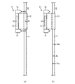
- FIG. 1 is a diagram showing an example of an elevator device according to Embodiment 1;
- FIG. It is the figure which expanded the A section of FIG.
- FIG. 3 is a view showing a BB cross section of FIG. 2;
- 9 is a flowchart showing another operation example of the inspection device;
- FIG. 10 is a diagram showing another example of hardware resources of a control device;
- FIG. 1 is a diagram showing an example of an elevator device according to Embodiment 1.
- the elevator system comprises a car 1 and a counterweight 2.
- the car 1 moves up and down in the hoistway 3 .
- a counterweight 2 moves up and down the hoistway 3 .
- a car 1 and a counterweight 2 are suspended in a hoistway 3 by ropes 4 .
- the rope 4 is, for example, a wire rope.
- the rope 4 is wound around the hoist 5. Specifically, the rope 4 is wound around the drive sheave 6 of the hoisting machine 5 .
- a hoist 5 drives the car 1 .
- the control device 7 controls the hoist 5 . That is, movement of the car 1 is controlled by the control device 7 .
- Fig. 1 shows a 2:1 roping elevator system as an example.
- the hoist 5 is provided at the top of the hoistway 3 .
- One end 4 a of the rope 4 is supported by a fixed body provided at the top of the hoistway 3 .
- the rope 4 extends downward from the end 4a.
- the rope 4 is wound around the sling sheave 8, the sling sheave 9, the drive sheave 6, and the sling sheave 10 in this order from the end 4a side.
- the other end 4 b of the rope 4 is supported by a fixed body provided at the top of the hoistway 3 .
- the hanging wheel 8 and the hanging wheel 9 are provided in the car 1.
- a hanging wheel 10 is provided on the counterweight 2 .
- the elevator system may be provided with other pulleys not shown in FIG.
- the rope 4 is formed by twisting a plurality of strands.
- a strand is formed by twisting a plurality of strands.
- the rope 4 is repeatedly bent by each pulley such as the drive sheave 6 and deteriorates. As the deterioration of the rope 4 progresses, the wire may break. If the deterioration of the rope 4 progresses further, the strand may break. Breakage of the wire also occurs when foreign matter is caught between the rope 4 and the pulley. In the following description, the broken portion of the wire is also referred to as broken portion 4c.
- the inspection device 11 is a device for inspecting the rope 4.
- a maintenance worker of the elevator inspects the rope 4 using the inspection device 11, for example, in a periodic inspection.
- the maintenance staff When inspecting the rope 4, the maintenance staff first gets on the car 1 and stops the car 1 at the landing on the top floor. Next, the maintenance worker installs the inspection device 11 on the car 1 .
- FIG. 1 shows an example in which the inspection device 11 is provided at the top of the hoistway 3 .
- FIG. 2 is an enlarged view of part A in FIG.
- FIG. 3 is a diagram showing a BB section of FIG.
- FIG. 4 is a diagram for explaining the functions of the inspection device 11.
- the inspection device 11 comprises a support 12 , a detector 13 , a marking device 14 , a marking device 15 and a control device 16 .
- Support 12 supports detector 13 , marking device 14 , marking device 15 and control device 16 .
- the detector 13 is provided with a specific detection area.
- the detector 13 is formed with a groove 13a having a U-shaped cross section.
- the space inside the groove 13a is the detection area.
- the detector 13 detects that the broken portion 4c exists in the portion of the rope 4 located in this detection area.
- Detector 13 may detect the presence of break 4c by any method. As an example, detector 13 detects the presence of break 4c using the leakage flux method.
- FIG. 1 shows a preferred example in which the part of the rope 4 extending downward from the hoisting machine 5 is arranged in the detection area of the detector 13 .
- the marking device 14 and the marking device 15 are devices for marking the rope 4. Any method may be used to mark the rope 4 . As an example, the marking process is performed by spraying the rope 4 with paint. Alternatively, the marking process may be performed by applying ink to the rope 4 with a pen or brush or the like.
- the detector 13 is arranged between the marking device 14 and the marking device 15 . That is, the marking device 14 and the marking device 15 can mark a portion of the rope 4 immediately before entering the detection area and a portion immediately after exiting the detection area.
- the marking device 14 is a device for marking one portion of the rope 4 extending from the detection area.
- the marking device 15 is a device for marking the other portion of the rope 4 extending from the detection area.
- the portion of the rope 4 extending downward from the hoisting machine 5 is arranged in the detection area of the detector 13 .
- marking device 14 is positioned above detector 13 . That is, the marking device 14 is arranged so as to be able to perform the marking process on the part of the rope 4 that extends upward from the detection area.
- a marking device 15 is arranged below the detector 13 . That is, the marking device 15 is arranged so as to be able to perform the marking process on the part of the rope 4 that extends downward from the detection area.
- the control device 16 controls the marking device 14 and the marking device 15 according to the detection result of the detector 13.
- the control device 16 includes a determination section 21 and a control section 22 .
- FIG. 5 is a flowchart showing an operation example of the inspection device 11.
- FIG. FIG. 6 is a diagram for explaining the functions of the inspection device 11. As shown in FIG. FIG. 6 is a diagram corresponding to FIG.
- the determination unit 21 determines whether or not the fractured portion 4c exists (S101). If the presence of the broken portion 4c is not detected by the detector 13, it is determined as No in S101. When the detector 13 detects the presence of the broken portion 4c, the determination in S101 is Yes.
- FIG. 6(a) shows a state in which the breaking portion 4c is arranged in the detection area. That is, in the state shown in FIG. 6A, it is determined as Yes in S101. If determined as Yes in S101, the control unit 22 causes both the marking device 14 and the marking device 15 to perform the marking process (S102). For example, in S ⁇ b>102 , paint is sprayed from the marking device 14 onto the part of the rope 4 that is positioned directly above the detection area. At the same time, paint is sprayed from the marking device 15 onto the portion of the rope 4 that is located directly below the detection area.
- FIG. 6(b) shows a state in which the breaking portion 4c has moved below the detection area.
- the fracture portion 4c exists between the mark 14a made by the marking device 14 and the mark 15a made by the marking device 15.
- FIG. 6(b) shows a state in which the breaking portion 4c has moved below the detection area.
- the detector 13 is arranged between the marking device 14 and the marking device 15 . Therefore, the marking device 14 and the marking device 15 can mark both the portion of the rope 4 immediately before entering the detection area and the portion immediately after exiting the detection area.
- the inspection apparatus 11 there is no need to equip the inspection apparatus 11 with a movable part or the like, and the structure can be simplified. Further, in the example shown in the present embodiment, marking can be performed at an appropriate position with respect to the breaking portion 4c.
- both the marking device 14 and the marking device 15 perform marking processing at the same time. After stopping the car 1 at the landing on the lowest floor, the maintenance personnel removes the portion of the rope 4 placed between the mark 14a marked by the marking device 14 and the mark 15a marked by the marking device 15. should be investigated. Therefore, the time and effort required for inspecting the rope 4 can be reduced. Further, in the example shown in the present embodiment, the effects described above can be obtained regardless of the moving direction of the rope 4 .
- the control device 16 may further include a direction detection section 23, as shown in FIG.
- the direction detector 23 detects the direction in which the rope 4 moves.
- the direction detection unit 23 may detect the moving direction of the rope 4 by any method.
- the inspection device 11 includes an input device 17 for manually inputting information by the user. In this case, the direction detection unit 23 detects the direction in which the rope 4 moves based on the information input from the input device 17 .
- the direction detection unit 23 detects that the moving direction of the rope 4 is the first direction if the first button is pressed. Detect if there is.
- the first direction is the direction in which the portion of the rope 4 facing the marking device 15 approaches the detection area. In the example shown in this embodiment, when the car 1 moves upward, the rope 4 moves in the first direction.
- the direction detection unit 23 detects that the moving direction of the rope 4 is the second direction if the second button is pressed.
- the second direction is the direction in which the portion of the rope 4 facing the marking device 14 approaches the detection area. That is, the second direction is a direction opposite to the first direction. In the example shown in this embodiment, when the car 1 moves downward, the rope 4 moves in the second direction.
- the inspection device 11 may include a roller 18 that contacts the rope 4.
- FIG. 7 is a diagram showing another example of the inspection device 11. As shown in FIG. FIG. 7 shows an example in which roller 18 is built into detector 13 . In the example shown in FIG. 7, the direction detection unit 23 detects the direction in which the rope 4 moves based on the direction in which the roller 18 rotates.
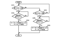
- FIG. 8 is a flowchart showing another operation example of the inspection device 11.
- the control device 16 includes the direction detection unit 23 .
- the control device 16 determines the moving direction of the rope 4 . For example, when the direction detection unit 23 detects that the rope 4 is moving in the first direction, it is determined as Yes in S201. When the direction detection unit 23 detects that the rope 4 is moving in the second direction, the determination in S202 is Yes.
- S201 if the car 1 is moving upward, S201 is determined to be Yes. If it is determined as Yes in S201, the determining section 21 determines whether or not the fracture portion 4c exists (S203).
- the processing shown in S203 is the same as the processing shown in S101. When the detector 13 detects the presence of the broken portion 4c, the determination in S203 is Yes.
- the controller 22 instructs the marking device 14 to carry out the marking process. (S204).
- the control unit 22 does not allow the marking device 15 to perform the marking process. At this time, the control unit 22 may control the marking device 14 so that the mark 14a is also attached to the fractured portion 4c.
- the control device 16 may further include a speed detection section 24 .
- the speed detector 24 detects the speed at which the rope 4 moves. If the inspection device 11 is provided with the rollers 18, the speed detection unit 24 can detect the speed at which the rope 4 moves from the speed at which the rollers 18 rotate.
- the speed detection unit 24 does not have to be able to detect the speed at which the rope 4 moves as a specific numerical value.
- a third button and a fourth button are further provided on the inspection device 11 as the input device 17 .
- the speed detection unit 24 detects that the rope 4 is moving at high speed if the third button is pressed.
- the speed detector 24 detects that the rope 4 is moving at a low speed if the fourth button is pressed.
- the inspection device 11 may further include a fifth button as the input device 17 for detecting that the rope 4 is moving at medium speed.
- control unit 22 may control the marking device 14 based on the speed detected by the speed detection unit 24 in S204. For example, the control unit 22 determines the start timing and end timing of the marking process based on the speed. As another example, the control unit 22 may determine the end timing of the marking process based on the speed so that the mark 14a is also attached to the fractured portion 4c.
- the determination unit 21 determines whether or not the fractured portion 4c exists (S205).
- the processing shown in S205 is the same as the processing shown in S101.
- the determination in S205 is Yes.
- the control unit 22 instructs the marking device 15 to carry out the marking process. (S206). In S206, the control unit 22 does not allow the marking device 14 to perform the marking process. At this time, the control unit 22 may control the marking device 15 so that the mark 15a is also attached to the fractured portion 4c.
- control unit 22 may control the marking device 15 based on the speed detected by the speed detection unit 24 in S206. For example, the control unit 22 determines the start timing and end timing of the marking process based on the speed. As another example, the control unit 22 may determine the end timing of the marking process based on the speed so that the mark 15a is also attached to the fractured portion 4c.
- FIG. 9 is a diagram showing an example of hardware resources of the control device 16.
- the control device 16 includes a processing circuit 30 including a processor 31 and a memory 32 as hardware resources.
- a plurality of processors 31 may be included in the processing circuitry 30 .
- a plurality of memories 32 may be included in the processing circuitry 30 .
- each part indicated by reference numerals 21 to 24 indicates the function of the control device 16.
- the function of each unit indicated by reference numerals 21 to 24 can be realized by software described as a program, firmware, or a combination of software and firmware.
- the program is stored in memory 32 .
- the control device 16 implements the functions of the units indicated by reference numerals 21 to 24 by causing the processor 31 to execute programs stored in the memory 32 .
- a semiconductor memory or the like can be used as the memory 32 .
- FIG. 10 is a diagram showing another example of hardware resources of the control device 16.
- controller 16 comprises processing circuitry 30 including processor 31 , memory 32 and dedicated hardware 33 .
- FIG. 10 shows an example in which a part of the functions of the control device 16 are implemented by dedicated hardware 33 . All the functions of the control device 16 may be realized by dedicated hardware 33 .
- Dedicated hardware 33 can be a single circuit, multiple circuits, programmed processors, parallel programmed processors, ASICs, FPGAs, or combinations thereof.
- a device for inspecting the rope 4 has been described in this embodiment. This is an example.
- the inspection device 11 may be used to inspect other ropes provided in the elevator system. Also, the inspection device 11 may be used to inspect ropes provided in equipment other than the elevator device.
- the inspection device according to the present disclosure can be used to inspect ropes.
Abstract
Description
図1は、実施の形態1におけるエレベーター装置の例を示す図である。エレベーター装置は、かご1及びつり合いおもり2を備える。かご1は、昇降路3を上下に移動する。つり合いおもり2は、昇降路3を上下に移動する。かご1及びつり合いおもり2は、ロープ4によって昇降路3に吊り下げられる。ロープ4は、例えばワイヤロープである。 Embodiment 1.
FIG. 1 is a diagram showing an example of an elevator device according to Embodiment 1. FIG. The elevator system comprises a car 1 and a
Claims (7)
- ロープを検査するための装置であって、
前記ロープのうち特定の検出領域に配置された部分に破断部が存在することを検出するための検出器と、
前記ロープのうち前記検出領域から延びる一方の部分にマーキング処理を行うための第1マーキング装置と、
前記ロープのうち前記検出領域から延びるもう一方の部分にマーキング処理を行うための第2マーキング装置と、
前記検出器の検出結果に応じて、前記第1マーキング装置及び前記第2マーキング装置を制御する制御手段と、
を備えた検査装置。 A device for inspecting a rope, comprising:
a detector for detecting the presence of a break in a portion of the rope located in a specific detection area;
a first marking device for marking one portion of the rope extending from the detection area;
a second marking device for marking the other portion of the rope extending from the detection area;
Control means for controlling the first marking device and the second marking device according to the detection result of the detector;
inspection equipment. - 前記制御手段は、破断部が存在することが前記検出器によって検出されると、前記第1マーキング装置及び前記第2マーキング装置の双方にマーキング処理を行わせる請求項1に記載の検査装置。 The inspection apparatus according to claim 1, wherein the control means causes both the first marking device and the second marking device to perform marking processing when the detector detects that a breakage exists.
- 前記ロープが移動する方向を検出する方向検出手段を更に備え、
前記制御手段は、
前記ロープが第1方向に移動している時に破断部が存在することが前記検出器によって検出されると、前記第1マーキング装置にマーキング処理を行わせ、
前記第1方向とは逆の第2方向に前記ロープが移動している時に破断部が存在することが前記検出器によって検出されると、前記第2マーキング装置にマーキング処理を行わせ、
前記第1方向は、前記ロープのうち前記第2マーキング装置に対向する部分が前記検出領域に近づく方向である請求項1に記載の検査装置。 Further comprising direction detection means for detecting the direction in which the rope moves,
The control means is
causing the first marking device to perform a marking process when the detector detects that there is a break while the rope is moving in the first direction;
causing the second marking device to perform a marking process when the detector detects that there is a break while the rope is moving in a second direction opposite to the first direction;
2. The inspection apparatus according to claim 1, wherein the first direction is a direction in which a portion of the rope facing the second marking device approaches the detection area. - 利用者が手動で情報を入力するための入力装置を更に備え、
前記方向検出手段は、前記入力装置から入力された情報に基づいて、前記ロープが移動する方向を検出する請求項3に記載の検査装置。 Further comprising an input device for the user to manually enter information,
4. The inspection apparatus according to claim 3, wherein said direction detection means detects the direction in which said rope moves based on information input from said input device. - 前記ロープが移動する速度を検出する速度検出手段を更に備え、
前記制御手段は、前記速度検出手段によって検出された速度に基づいて、前記第1マーキング装置及び前記第2マーキング装置によるマーキング処理の終了タイミングを決定する請求項3又は請求項4に記載の検査装置。 Further comprising speed detection means for detecting the speed at which the rope moves,
5. The inspection apparatus according to claim 3, wherein the control means determines the end timing of marking processing by the first marking device and the second marking device based on the speed detected by the speed detection means. . - 昇降路を移動するかごと、
前記かごを吊り下げるロープと、
前記ロープが巻き掛けられた巻上機と、
前記ロープを検査するための検査装置と、
を備え、
前記検査装置は、
前記ロープのうち特定の検出領域に配置された部分に破断部が存在することを検出するための検出器と、
前記ロープのうち前記検出領域から上方に延びる部分にマーキング処理を行うための第1マーキング装置と、
前記ロープのうち前記検出領域から下方に延びる部分にマーキング処理を行うための第2マーキング装置と、
前記検出器の検出結果に応じて、前記第1マーキング装置及び前記第2マーキング装置を制御する制御手段と、
を備えたエレベーター装置。 A car traveling in a hoistway,
a rope for suspending the basket;
a hoist around which the rope is wound;
an inspection device for inspecting the rope;
with
The inspection device is
a detector for detecting the presence of a break in a portion of the rope located in a specific detection area;
a first marking device for marking a portion of the rope extending upward from the detection area;
a second marking device for marking a portion of the rope extending downward from the detection area;
Control means for controlling the first marking device and the second marking device according to the detection result of the detector;
Elevator device with - 前記巻上機は、前記昇降路の頂部に設けられ、
前記検査装置は、前記昇降路の頂部に設けられ、
前記ロープのうち前記巻上機から下方に延びる部分が前記検出領域に配置された請求項6に記載のエレベーター装置。 The hoist is provided at the top of the hoistway,
The inspection device is provided at the top of the hoistway,
7. An elevator apparatus according to claim 6, wherein a portion of said rope extending downwardly from said hoist is disposed in said detection area.
Priority Applications (4)
| Application Number | Priority Date | Filing Date | Title |
|---|---|---|---|
| PCT/JP2021/027329 WO2023002603A1 (en) | 2021-07-21 | 2021-07-21 | Inspection device and elevator device |
| JP2023536293A JP7414189B2 (en) | 2021-07-21 | 2021-07-21 | Inspection equipment and elevator equipment |
| CN202180100806.6A CN117693485A (en) | 2021-07-21 | 2021-07-21 | Inspection device and elevator device |
| KR1020247004570A KR20240023692A (en) | 2021-07-21 | 2021-07-21 | inspection device and elevator device |
Applications Claiming Priority (1)
| Application Number | Priority Date | Filing Date | Title |
|---|---|---|---|
| PCT/JP2021/027329 WO2023002603A1 (en) | 2021-07-21 | 2021-07-21 | Inspection device and elevator device |
Publications (1)
| Publication Number | Publication Date |
|---|---|
| WO2023002603A1 true WO2023002603A1 (en) | 2023-01-26 |
Family
ID=84979055
Family Applications (1)
| Application Number | Title | Priority Date | Filing Date |
|---|---|---|---|
| PCT/JP2021/027329 WO2023002603A1 (en) | 2021-07-21 | 2021-07-21 | Inspection device and elevator device |
Country Status (4)
| Country | Link |
|---|---|
| JP (1) | JP7414189B2 (en) |
| KR (1) | KR20240023692A (en) |
| CN (1) | CN117693485A (en) |
| WO (1) | WO2023002603A1 (en) |
Citations (3)
| Publication number | Priority date | Publication date | Assignee | Title |
|---|---|---|---|---|
| JPS59154354A (en) * | 1983-02-23 | 1984-09-03 | Hitachi Ltd | Indicating device of damaged part of long-sized magnetic body |
| JP2004149317A (en) * | 2002-09-04 | 2004-05-27 | Toshiba Elevator Co Ltd | Rope abnormality detector |
| JP2015036319A (en) * | 2013-08-12 | 2015-02-23 | 東芝エレベータ株式会社 | Main rope inspection device for elevator |
Family Cites Families (1)
| Publication number | Priority date | Publication date | Assignee | Title |
|---|---|---|---|---|
| JP2010030765A (en) | 2008-07-30 | 2010-02-12 | Mitsubishi Electric Building Techno Service Co Ltd | Elevator main rope inspecting device |
-
2021
- 2021-07-21 WO PCT/JP2021/027329 patent/WO2023002603A1/en active Application Filing
- 2021-07-21 JP JP2023536293A patent/JP7414189B2/en active Active
- 2021-07-21 KR KR1020247004570A patent/KR20240023692A/en active Search and Examination
- 2021-07-21 CN CN202180100806.6A patent/CN117693485A/en active Pending
Patent Citations (3)
| Publication number | Priority date | Publication date | Assignee | Title |
|---|---|---|---|---|
| JPS59154354A (en) * | 1983-02-23 | 1984-09-03 | Hitachi Ltd | Indicating device of damaged part of long-sized magnetic body |
| JP2004149317A (en) * | 2002-09-04 | 2004-05-27 | Toshiba Elevator Co Ltd | Rope abnormality detector |
| JP2015036319A (en) * | 2013-08-12 | 2015-02-23 | 東芝エレベータ株式会社 | Main rope inspection device for elevator |
Also Published As
| Publication number | Publication date |
|---|---|
| JP7414189B2 (en) | 2024-01-16 |
| JPWO2023002603A1 (en) | 2023-01-26 |
| KR20240023692A (en) | 2024-02-22 |
| CN117693485A (en) | 2024-03-12 |
Similar Documents
| Publication | Publication Date | Title |
|---|---|---|
| JP4850477B2 (en) | Elevator apparatus automatic inspection method and elevator control apparatus | |
| JP5759938B2 (en) | Elevator rope inspection method | |
| JP2015048202A (en) | Elevator control device | |
| JP5308467B2 (en) | Double deck elevator and how to adjust the car spacing | |
| WO2023002603A1 (en) | Inspection device and elevator device | |
| JP5730358B2 (en) | Elevator main rope inspection device | |
| JP5334868B2 (en) | Elevator equipment | |
| JP2016060550A (en) | Life diagnosis method of elevator main rope | |
| JP6657368B1 (en) | Group management elevator operation control method and group management control device | |
| KR20130117834A (en) | Double-deck elevator | |
| US20190322482A1 (en) | Automatic cognitive analysis of elevators to reduce passenger wait time | |
| JP6844431B2 (en) | Elevator rope inspection device | |
| JP5293746B2 (en) | Elevator control device | |
| JP2009196770A (en) | Control device and control method of elevator and renovation method of existing elevator | |
| CN109850714A (en) | Elevator | |
| JP2020007078A (en) | Notification apparatus and notification method | |
| US11511964B2 (en) | System for monitoring lobby activity to determine whether to cancel elevator service | |
| JP2018087073A (en) | Inspection supporting system for elevator rope | |
| JP7185856B2 (en) | elevator system | |
| JP2014162621A (en) | Main rope inspection device of elevator | |
| JP2019163152A (en) | Operation control method for group management elevator and group management elevator system | |
| JPWO2023002603A5 (en) | ||
| JP2016204118A (en) | Oil supply device for main rope | |
| CN105173938B (en) | Elevator device | |
| JPWO2005077804A1 (en) | Elevator equipment |
Legal Events
| Date | Code | Title | Description |
|---|---|---|---|
| 121 | Ep: the epo has been informed by wipo that ep was designated in this application |
Ref document number: 21950953 Country of ref document: EP Kind code of ref document: A1 |
|
| WWE | Wipo information: entry into national phase |
Ref document number: 2023536293 Country of ref document: JP |
|
| ENP | Entry into the national phase |
Ref document number: 20247004570 Country of ref document: KR Kind code of ref document: A |
|
| WWE | Wipo information: entry into national phase |
Ref document number: 1020247004570 Country of ref document: KR |
|
| NENP | Non-entry into the national phase |
Ref country code: DE |