WO2023002567A1 - 切削工具および切削装置 - Google Patents
切削工具および切削装置 Download PDFInfo
- Publication number
- WO2023002567A1 WO2023002567A1 PCT/JP2021/027146 JP2021027146W WO2023002567A1 WO 2023002567 A1 WO2023002567 A1 WO 2023002567A1 JP 2021027146 W JP2021027146 W JP 2021027146W WO 2023002567 A1 WO2023002567 A1 WO 2023002567A1
- Authority
- WO
- WIPO (PCT)
- Prior art keywords
- housing
- cutting
- cutting tool
- power
- battery
- Prior art date
- Legal status (The legal status is an assumption and is not a legal conclusion. Google has not performed a legal analysis and makes no representation as to the accuracy of the status listed.)
- Ceased
Links
Images



Classifications
-
- B—PERFORMING OPERATIONS; TRANSPORTING
- B26—HAND CUTTING TOOLS; CUTTING; SEVERING
- B26D—CUTTING; DETAILS COMMON TO MACHINES FOR PERFORATING, PUNCHING, CUTTING-OUT, STAMPING-OUT OR SEVERING
- B26D5/00—Arrangements for operating and controlling machines or devices for cutting, cutting-out, stamping-out, punching, perforating, or severing by means other than cutting
- B26D5/08—Means for actuating the cutting member to effect the cut
- B26D5/086—Electric, magnetic, piezoelectric, electro-magnetic means
-
- B—PERFORMING OPERATIONS; TRANSPORTING
- B23—MACHINE TOOLS; METAL-WORKING NOT OTHERWISE PROVIDED FOR
- B23B—TURNING; BORING
- B23B27/00—Tools for turning or boring machines; Tools of a similar kind in general; Accessories therefor
- B23B27/14—Cutting tools of which the bits or tips or cutting inserts are of special material
-
- B—PERFORMING OPERATIONS; TRANSPORTING
- B23—MACHINE TOOLS; METAL-WORKING NOT OTHERWISE PROVIDED FOR
- B23B—TURNING; BORING
- B23B29/00—Holders for non-rotary cutting tools; Boring bars or boring heads; Accessories for tool holders
- B23B29/24—Tool holders for a plurality of cutting tools, e.g. turrets
- B23B29/242—Turrets, without description of the angular positioning device
-
- B—PERFORMING OPERATIONS; TRANSPORTING
- B23—MACHINE TOOLS; METAL-WORKING NOT OTHERWISE PROVIDED FOR
- B23Q—DETAILS, COMPONENTS, OR ACCESSORIES FOR MACHINE TOOLS, e.g. ARRANGEMENTS FOR COPYING OR CONTROLLING; MACHINE TOOLS IN GENERAL CHARACTERISED BY THE CONSTRUCTION OF PARTICULAR DETAILS OR COMPONENTS; COMBINATIONS OR ASSOCIATIONS OF METAL-WORKING MACHINES, NOT DIRECTED TO A PARTICULAR RESULT
- B23Q17/00—Arrangements for observing, indicating or measuring on machine tools
- B23Q17/09—Arrangements for observing, indicating or measuring on machine tools for indicating or measuring cutting pressure or for determining cutting-tool condition, e.g. cutting ability, load on tool
- B23Q17/0952—Arrangements for observing, indicating or measuring on machine tools for indicating or measuring cutting pressure or for determining cutting-tool condition, e.g. cutting ability, load on tool during machining
-
- B—PERFORMING OPERATIONS; TRANSPORTING
- B26—HAND CUTTING TOOLS; CUTTING; SEVERING
- B26D—CUTTING; DETAILS COMMON TO MACHINES FOR PERFORATING, PUNCHING, CUTTING-OUT, STAMPING-OUT OR SEVERING
- B26D11/00—Combinations of several similar cutting apparatus
-
- B—PERFORMING OPERATIONS; TRANSPORTING
- B23—MACHINE TOOLS; METAL-WORKING NOT OTHERWISE PROVIDED FOR
- B23B—TURNING; BORING
- B23B2260/00—Details of constructional elements
- B23B2260/024—Batteries
-
- B—PERFORMING OPERATIONS; TRANSPORTING
- B23—MACHINE TOOLS; METAL-WORKING NOT OTHERWISE PROVIDED FOR
- B23B—TURNING; BORING
- B23B2260/00—Details of constructional elements
- B23B2260/10—Magnets
-
- B—PERFORMING OPERATIONS; TRANSPORTING
- B23—MACHINE TOOLS; METAL-WORKING NOT OTHERWISE PROVIDED FOR
- B23B—TURNING; BORING
- B23B2260/00—Details of constructional elements
- B23B2260/128—Sensors
-
- B—PERFORMING OPERATIONS; TRANSPORTING
- B23—MACHINE TOOLS; METAL-WORKING NOT OTHERWISE PROVIDED FOR
- B23B—TURNING; BORING
- B23B2260/00—Details of constructional elements
- B23B2260/128—Sensors
- B23B2260/1285—Vibration sensors
-
- B—PERFORMING OPERATIONS; TRANSPORTING
- B23—MACHINE TOOLS; METAL-WORKING NOT OTHERWISE PROVIDED FOR
- B23Q—DETAILS, COMPONENTS, OR ACCESSORIES FOR MACHINE TOOLS, e.g. ARRANGEMENTS FOR COPYING OR CONTROLLING; MACHINE TOOLS IN GENERAL CHARACTERISED BY THE CONSTRUCTION OF PARTICULAR DETAILS OR COMPONENTS; COMBINATIONS OR ASSOCIATIONS OF METAL-WORKING MACHINES, NOT DIRECTED TO A PARTICULAR RESULT
- B23Q2220/00—Machine tool components
- B23Q2220/002—Tool turrets
-
- Y—GENERAL TAGGING OF NEW TECHNOLOGICAL DEVELOPMENTS; GENERAL TAGGING OF CROSS-SECTIONAL TECHNOLOGIES SPANNING OVER SEVERAL SECTIONS OF THE IPC; TECHNICAL SUBJECTS COVERED BY FORMER USPC CROSS-REFERENCE ART COLLECTIONS [XRACs] AND DIGESTS
- Y02—TECHNOLOGIES OR APPLICATIONS FOR MITIGATION OR ADAPTATION AGAINST CLIMATE CHANGE
- Y02E—REDUCTION OF GREENHOUSE GAS [GHG] EMISSIONS, RELATED TO ENERGY GENERATION, TRANSMISSION OR DISTRIBUTION
- Y02E60/00—Enabling technologies; Technologies with a potential or indirect contribution to GHG emissions mitigation
- Y02E60/10—Energy storage using batteries
Definitions
- the present disclosure relates to cutting tools and cutting devices.
- Patent Document 1 discloses a cutting tool attached to a turret.
- a cutting tool includes a cutting tool, a power path, and a housing.
- the cutting bit includes a cutting edge, a shank holding the cutting edge, and a sensor attached to the shank.
- a power path has a first end connected to the cutting bit and a second end opposite the first end and provides power to the sensor.
- the housing houses a battery storing power to be supplied to the power path and is connected to the second end.
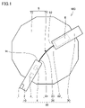
- FIG. 1 is a schematic plan view showing configurations of a cutting device and a cutting tool according to the first embodiment.
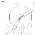
- FIG. 2 is a schematic plan view showing configurations of a cutting device and a cutting tool according to the second embodiment.
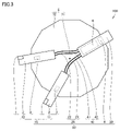
- FIG. 3 is a schematic plan view showing configurations of a cutting device and a cutting tool according to the third embodiment.
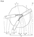
- FIG. 4 is a schematic plan view showing configurations of a cutting device and a cutting tool according to the fourth embodiment.
- FIG. 5 is a schematic plan view showing configurations of a cutting device and a cutting tool according to the fifth embodiment.
- FIG. 6 is a schematic plan view showing configurations of a cutting device and a cutting tool according to the sixth embodiment.
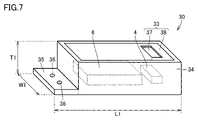
- FIG. 7 is a schematic perspective view showing the configuration of the housing.
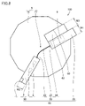
- FIG. 8 is a schematic plan view showing the first mounting method of the housing.
- FIG. 9 is a schematic partial cross-sectional view showing a second mounting method of the housing.
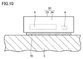
- FIG. 10 is a schematic partial cross-section
- An object of the present disclosure is to provide a cutting tool and cutting apparatus capable of improving productivity in cutting.
- ADVANTAGE OF THE INVENTION According to this indication, the cutting tool and cutting device which can improve productivity in cutting can be provided.
- a cutting tool 80 includes a cutting tool 10, a power path 20, and a housing 30.
- a cutting tool 10 includes a cutting edge 1 , a shank 2 holding the cutting edge 1 , and a sensor 3 attached to the shank 2 .
- the power path 20 has a first end 81 connected to the cutting bit 10 and a second end 82 opposite the first end 81 and supplies power to the sensor 3 .
- the housing 30 accommodates the battery 6 storing power to be supplied to the power path 20 and is connected to the second end 82 . Accordingly, the housing 30 can be equipped with a large-capacity battery 6 , and the battery 6 can be used to supply power to the sensor 3 . Therefore, the sensor 3 can be operated for a long time. As a result, productivity in cutting can be improved.
- the cutting tool 80 according to (1) above may further include a communication device 4 that transmits data measured by the sensor 3 to the outside.
- the communication device 4 may be housed in the housing 30 .
- a recess is provided in the shank 2 and the communication device 4 is accommodated in the recess. In this case, the rigidity of the shank 2 is lowered.
- the communication device 4 is housed in the housing 30 , it is not necessary to form a recess for housing the communication device 4 in the shank 2 . Therefore, it is possible to prevent the rigidity of the cutting bit 10 from decreasing.
- the cutting bit 10 may include a first bit 11 and a second bit 12 different from the first bit 11 .
- Power may be branched from the housing 30 to the first byte 11 and the second byte 12 . This allows power to be supplied from one battery 6 to a plurality of bytes. Moreover, data measured by each sensor 3 of a plurality of bytes can be transmitted to the outside by one communication device 4 . Compared to using a plurality of communication devices 4, the amount of wireless communication can be reduced. Also, radio interference can be suppressed.
- the cutting tool 80 according to (2) or (3) above has a third end 83 connected to the cutting bit 10 and a fourth end 84 opposite to the third end 83. and a signal path 40 for transmitting data to the communication device 4 .
- data can be efficiently transmitted to the communication device 4 using the signal path 40 different from the power path 20 .
- the power path 20 may be a heat-resistant cable. Chips of the work material cut by the cutting bit 10 have a high temperature of, for example, 200° C. or higher. If hot chips contact the power path 20, the power path 20 may be damaged. By using a heat-resistant cable as the power line 20, it is possible to suppress damage to the power line 20 due to chips.
- the cutting tool 80 may further include an inclination detection sensor 7 capable of recognizing the position of the housing 30 .
- the tilt detection sensor 7 may be housed in the housing 30 .
- the position of the cutting tool 10 can be identified based on the position of the housing 30 because the positional relationship between the cutting tool 10 and the housing 30 is fixed. .
- power can be supplied only to the sensor 3 of the cutting tool 10 that is in use without supplying power to the sensor 3 of the cutting tool 10 that is not in use. Therefore, power consumption of the battery 6 can be reduced.
- At least part of the side surface of the housing 30 may be made of resin. Compared to metal, resin easily passes radio waves. By making a part of the side surface of the housing 30 made of resin, the wireless signal can be efficiently transmitted from the communication device 4 arranged inside the housing 30 to the outside.
- the power path 20 includes a first power line portion 24 having a first end portion 81 and a second power line portion having a second end portion 82. 25 , a first connector 26 attached to the first power line portion 24 , and a second connector 27 attached to the second power line portion 25 .
- the first connector 26 may be connected with the second connector 27 .
- the housing 30 may have a power connector 51 . Thereby, another housing 30 connected to the power connector 51 can be added.
- the housing 30 includes a first housing portion 31 and a second housing portion 32 different from the first housing portion 31.
- the battery 6 may include a first battery section 61 housed in the first housing section 31 and a second battery section 62 housed in the second housing section 32 .
- the first battery section 61 may be electrically connected to the second battery section 62 .
- the cutting device 100 may include the cutting tool 80 according to any one of (1) to (10) above and the turret 5 to which the cutting tool 80 is attached.
- the cutting bit 10 may have a first end face 91 facing the central axis 71 of the turret 5 .
- the housing 30 may have a second end surface 92 facing the central axis 71 .
- the power path 20 may connect the first end surface 91 and the second end surface 92 . As a result, even when the turret 5 is rotated, it is possible to prevent the power path 20 from entangling with the workpiece or the like.
- the housing 30 may be fixed to the turret 5 using the fixing jig 63 . This allows the housing 30 to be fixed to the portion of the turret 5 to which another tool is attached.
- the housing 30 may be fixed to the turret 5 using screws 64 . This allows the housing 30 to be easily attached to the turret 5 .
- the housing 30 may be fixed to the turret 5 using magnets 70 . This allows the housing 30 to be easily attached to the turret 5 .
- FIG. 1 is a schematic plan view showing configurations of a cutting device 100 and a cutting tool 80 according to the first embodiment.
- the cutting device 100 mainly has a turret 5 and a cutting tool 80.
- the turret 5 is a platform for holding tools.
- the turret 5 has a tool mounting surface 72 and a central axis 71 .
- a plurality of tools are attached to the tool attachment surface 72 .
- Each of the plurality of tools is mounted around central axis 71 .
- the cutting bits are mounted radially around the central axis 71 .
- Turret 5 is pivotable around central axis 71 . By rotating the turret 5, the tool to be used can be easily switched.
- a cutting tool 80 is attached to the turret 5 .
- a cutting tool 80 mainly has a cutting bit 10 , a power path 20 and a housing 30 .
- the power path 20 may be arranged between the cutting bit 10 and the housing 30 when viewed in the direction along the central axis 71 .
- the cutting bit 10 may be arranged on the opposite side of the housing 30 when viewed from the central axis 71 .
- the cutting bit 10 may be positioned outside the power path 20 in the radial direction perpendicular to the central axis 71 .
- the housing 30 may be located outside the power path 20 in the radial direction perpendicular to the central axis 71 .
- the power path 20 may be positioned to overlap the turret 5 when viewed along the central axis 71 of the turret 5 .
- the cutting tool 10 may have a cutting edge 1, a shank 2, a sensor 3, and a communication device 4, for example.
- the cutting edge 1 may be a cutting insert.
- the cutting edge 1 cuts a work material.
- the cutting bit 10 may be a turning bit.
- a shank 2 holds the cutting edge 1 .
- Shank 2 may abut turret 5 .
- a sensor 3 is attached to the shank 2 .
- the sensor 3 is, for example, an acceleration sensor, strain sensor, sound sensor, or the like.
- the acceleration sensor can measure, for example, the period of vibration of the cutting tool 80, the amplitude of vibration, and the like.
- the strain sensor 3 can measure the degree of bending of the shank 2, for example.
- the sound sensor can measure, for example, the frequency of noise generated during cutting, the amplitude of noise, and the like.
- the power path 20 is connected to the cutting tool 10.
- the power path 20 supplies power to the sensor 3 of the cutting tool 10 .
- Power path 20 has a first end 81 , a second end 82 and a first intermediate path 23 .
- the second end 82 is opposite the first end 81 .
- the first intermediate passage 23 is located between the first end 81 and the second end 82 .
- the first end 81 is connected to the cutting bit 10 .
- the power path 20 is electrically connected to the cutting bit 10 at the first end 81 .
- Power path 20 is electrically connected to sensor 3 .
- the cutting tool 10 may have a connection wiring (not shown) that connects the first end 81 of the power path 20 and the sensor 3 .
- the cutting bit 10 has a first end surface 91 facing the central axis 71 of the turret 5 .
- the housing 30 has a second end face 92 facing the central axis 71 .
- the power path 20 may connect the first end surface 91 and the second end surface 92 .
- the first end portion 81 may be located on the first end surface 91 .
- the second end 82 may be located on the second end surface 92 .
- the power line 20 is, for example, a cable.
- Power path 20 may be a waterproof cable.
- the power line 20 may be a single-core cable or a multi-core cable.
- Power path 20 may have a braided shield.
- Power path 20 is, for example, a robot cable.
- the power path 20 may be, for example, FPC (Flexible Printed Circuits).
- the outer coating of the power line 20 may be made of fluorine resin, silicon, glass fiber, or the like, which has excellent heat resistance.
- the housing 30 accommodates the battery 6.
- the battery 6 stores power to be supplied to the power line 20 .
- battery 6 supplies power to sensor 3 via power path 20 .
- a second end 82 of power path 20 is connected to housing 30 .
- the power path 20 is electrically connected to the housing 30 at the second end 82 .
- Power path 20 is electrically connected to battery 6 .
- the housing 30 may have a connecting wire (not shown) that connects the second end 82 of the power path 20 and the battery 6 .
- the battery 6 is, for example, a mobile battery.
- the battery 6 may be a disposable primary battery or a secondary battery that can be used repeatedly by charging.
- the battery 6 may be a lithium secondary battery, an alkaline storage battery, or a lead storage battery.
- the battery 6 may be a solar cell or a fuel cell.
- the communication device 4 transmits the data measured by the sensor 3 to the outside.
- the communication device 4 is, for example, a wireless transmitter.
- the communication device 4 may transmit and receive data via radio signals, for example.
- the communication device 4 may have Bluetooth (registered trademark), a wireless LAN (Lacal Area Network) module, an infrared communication module, or the like.
- the configuration of the cutting tool 80 according to the second embodiment is different from the configuration of the cutting tool 80 according to the first embodiment mainly in that the communication device 4 is housed in the housing 30, and other configurations. is the same as the configuration of the cutting tool 80 according to the first embodiment.
- the configuration different from that of the cutting tool 80 according to the first embodiment will be mainly described.
- FIG. 2 is a schematic plan view showing configurations of a cutting device 100 and a cutting tool 80 according to the second embodiment.
- the communication device 4 may be housed in a housing 30. As shown in FIG. From another point of view, the communication device 4 may not be attached to the shank 2 of the cutting tool 10 .
- the cutting tool 80 of the cutting device 100 according to the second embodiment may further have a signal path 40 .
- a signal path 40 transmits data measured by the sensor 3 to the communication device 4 .
- the signal path 40 may be arranged between the cutting tool 10 and the housing 30 when viewed in the direction along the central axis 71 .
- the cutting bit 10 may be positioned outside the signal path 40 in the radial direction perpendicular to the central axis 71 .
- the housing 30 may be located outside the signal path 40 in the radial direction perpendicular to the central axis 71 .
- the signal path 40 has a third end 83 , a fourth end 84 and a second intermediate path 43 .
- the fourth end 84 is opposite the third end 83 .
- the second intermediate passage 43 is located between the third end 83 and the fourth end 84 .
- the third end 83 is connected to the cutting bit 10 . From another point of view, the signal path 40 is electrically connected to the cutting bit 10 at the third end 83 .
- Signal path 40 is electrically connected to sensor 3 .
- the cutting tool 10 may have a connection wiring (not shown) that connects the third end 83 of the signal path 40 and the sensor 3 .
- a fourth end 84 of the signal path 40 is connected to the housing 30 . From another perspective, signal path 40 is electrically connected to housing 30 at fourth end 84 . Signal path 40 is electrically connected to communication device 4 .
- the housing 30 may have connecting wiring (not shown) that connects the fourth end 84 of the signal path 40 and the communication device 4 .
- a battery 6 may power the communication device 4 .
- the signal path 40 is, for example, a cable.
- Signal path 40 may be a waterproof cable.
- the signal path 40 may be a single-core cable or a multi-core cable.
- Signal path 40 may have a braided shield.
- Signal path 40 may be, for example, a robot cable.
- Signal path 40 may be, for example, FPC.
- the outer coating of the signal path 40 may be made of fluorine resin, silicon, glass fiber, or the like, which has excellent heat resistance.
- Signal path 40 and power path 20 may be covered by a common outer coating.
- the configuration of the cutting tool 80 according to the third embodiment is different from the configuration of the cutting tool 80 according to the second embodiment mainly in that the cutting tool 10 has a plurality of cutting tools. is the same as the configuration of the cutting tool 80 according to the second embodiment.
- the configuration different from that of the cutting tool 80 according to the second embodiment will be mainly described.
- FIG. 3 is a schematic plan view showing configurations of a cutting device 100 and a cutting tool 80 according to the third embodiment.
- the cutting bit 10 may have a first bit 11 and a second bit 12 .
- Each of the first bite 11 and the second bite 12 is attached to the turret 5 .
- the second byte 12 is different from the first byte 11 .
- a second byte 12 is spaced from the first byte 11 .
- Each of the first bit 11 and the second bit 12 has a cutting edge 1 , a shank 2 and a sensor 3 .
- the power line 20 may have a first power line section 21 and a second power line section 22 .
- the first power path section 21 is connected to the first byte 11 .
- the first power path section 21 supplies power to the sensor 3 of the first byte 11 .
- the first power path section 21 is connected to the housing 30 .
- First power path portion 21 is electrically connected to battery 6 arranged in housing 30 .
- the second power path section 22 is connected to the second byte 12 .
- the second power path section 22 supplies power to the sensor 3 of the second byte 12 .
- the second power path section 22 is connected to the housing 30 .
- the second power path portion 22 is electrically connected to the battery 6 arranged in the housing 30 .
- the power supplied from the battery 6 may be branched and supplied from the housing 30 to the first byte 11 and the second byte 12 . Specifically, the power supplied from the battery 6 branches to the first power path portion 21 and the second power path portion 22 . Power supplied from the battery 6 is supplied to the sensor 3 of the first bite 11 via the first power path section 21 . Similarly, power supplied from the battery 6 is supplied to the sensor 3 of the second bite 12 via the second power path section 22 .
- the signal path 40 may have a first signal path portion 41 and a second signal path portion 42 .
- the first signal path portion 41 is electrically connected to the sensor 3 of the first byte 11 .
- the first signal path section 41 is electrically connected to the communication device 4 arranged in the housing 30 .
- the first signal path section 41 transmits data measured by the sensor 3 included in the first byte 11 to the communication device 4 .
- the second signal path portion 42 is electrically connected to the sensor 3 of the second byte 12 .
- the second signal path section 42 is electrically connected to the communication device 4 arranged in the housing 30 .
- the second signal path section 42 transmits data measured by the sensor 3 included in the second byte 12 to the communication device 4 . That is, data obtained from two sensors 3 may be transmitted to the outside using one communication device 4 .
- the configuration of the cutting tool 80 according to the fourth embodiment differs from the configuration of the cutting tool 80 according to the third embodiment mainly in that it includes the tilt detection sensor 7.
- Other configurations are as follows.
- the configuration is the same as that of the cutting tool 80 according to the third embodiment.
- the configuration different from that of the cutting tool 80 according to the third embodiment will be mainly described.
- FIG. 4 is a schematic plan view showing configurations of a cutting device 100 and a cutting tool 80 according to the fourth embodiment.
- a cutting tool 80 according to the fourth embodiment may have an inclination detection sensor 7 .
- the tilt detection sensor 7 can recognize the position of the housing 30 .
- the tilt detection sensor 7 is housed in the housing 30 .
- the tilt detection sensor 7 is, for example, an acceleration sensor or a gyro sensor. Each of the acceleration sensor and the gyro sensor can recognize the tilt of housing 30 by detecting the direction of gravity. Thereby, the position of the housing 30 can be recognized when the turret 5 is rotated.
- Each of housing 30 and cutting bit 10 is fixed to turret 5 . If the position of the housing 30 is known, the position of the cutting bit 10 can be recognized.
- the battery 6 may supply power to the tilt detection sensor 7 .
- the configuration of the cutting tool 80 according to the fifth embodiment differs from the configuration of the cutting tool 80 according to the first embodiment mainly in that the housing 30 has a plurality of housing parts. is the same as that of the cutting tool 80 according to the first embodiment.
- the configuration different from that of the cutting tool 80 according to the first embodiment will be mainly described.
- FIG. 5 is a schematic plan view showing configurations of a cutting device 100 and a cutting tool 80 according to the fifth embodiment.
- the housing 30 may have a first housing portion 31 and a second housing portion 32 .
- Each of the first housing portion 31 and the second housing portion 32 is attached to the turret 5 .
- the second housing portion 32 is different from the first housing portion 31 .
- the second housing portion 32 is separated from the first housing portion 31 .
- the first housing section 31 may have a first power connector 51 .
- the second housing portion 32 may have a second power connector 52 .
- a cutting tool 80 according to the fifth embodiment may further have connection wiring 8 .
- the connection wiring 8 electrically connects the first power connector 51 and the second power connector 52 .
- the battery 6 has a first battery section 61 and a second battery section 62 .
- the first battery section 61 is housed in the first housing section 31 .
- the second battery section 62 is housed in the second housing section 32 .
- the first battery section 61 is electrically connected to the second battery section 62 .
- the first battery section 61 and the second battery section 62 are connected in series, for example.
- the first battery section 61 and the second battery section 62 may be connected in parallel.
- the configuration of the cutting tool 80 according to the sixth embodiment differs from the configuration of the cutting tool 80 according to the first embodiment mainly in that the power path 20 is detachable with a connector. , is the same as the configuration of the cutting tool 80 according to the first embodiment.
- the configuration different from that of the cutting tool 80 according to the first embodiment will be mainly described.
- FIG. 6 is a schematic plan view showing configurations of a cutting device 100 and a cutting tool 80 according to the sixth embodiment.
- the power line 20 may have a first power line section 24 , a second power line section 25 , a first connector 26 and a second connector 27 .
- the first power line portion 24 has a first end portion 81 .
- the second power line portion 25 has a second end portion 82 .
- the first connector 26 is attached to the first power line section 24 .
- the first connector 26 is attached to the end of the first power line section 24 opposite the first end 81 .
- the second connector 27 is attached to the second power line section 25 .
- a second connector 27 is attached to the end of the second power line section 25 opposite the second end 82 .
- the first connector 26 is connected with the second connector 27 .
- the first connector 26 and the second connector 27 are detachable.
- Each of the first connector 26 and the second connector 27 may be waterproof connectors.
- FIG. 7 is a schematic perspective view showing the configuration of the housing 30.
- the housing 30 has, for example, a housing portion 34, a lid portion 33, and a mounting plate portion 35.
- the housing portion 34 is made of metal, for example.
- Each of the battery 6 and the communication device 4 is arranged inside the housing portion 34 .
- the housing portion 34 has a substantially rectangular parallelepiped shape.
- a lid portion 33 is arranged at the opening of the housing portion 34 .
- the lid portion 33 has, for example, a metal plate portion 38 and a resin window 37 .
- a resin window 37 may be fitted in a through hole provided in a portion of the metal plate portion 38 .
- the resin window 37 may face the communication device 4 .
- the metal plate portion 38 may face the battery 6 .
- the side surface of the housing 30 may be made of resin.
- a portion of the lid portion 33 may be made of resin, and a portion of the housing portion 34 may be made of resin. From another point of view, the portion of the lid portion 33 other than the resin window 37 may be made of metal.
- the mounting plate portion 35 may be arranged along the lateral side of the housing portion 34 .
- a plurality of mounting holes 36 may be provided in the mounting plate portion 35 .
- the longitudinal length of the housing 30 is the first length L1
- the lateral length of the housing 30 is the first width W1.
- the first length L1 is greater than the first width W1.
- the thickness of the housing 30 in the thickness direction of the lid portion 33 is a first thickness T1.
- the first thickness T1 may be smaller than each of the first length L1 and the first width W1.
- the lower limit of the first width W1 is not particularly limited, but may be, for example, 8 mm or more, 12 mm or more, 16 mm or more, or 20 mm or more, It may be 25 mm or more, 32 mm or more, or 40 mm or more.
- the upper limit of the first width W1 is not particularly limited, but may be, for example, 16 mm or less, 24 mm or less, 32 mm or less, or 40 mm or less, It may be 50 mm or less, 64 mm or less, or 80 mm or less.
- the lower limit of the first thickness T1 is not particularly limited, but may be, for example, 8 mm or more, 12 mm or more, 16 mm or more, or 20 mm or more, It may be 25 mm or more, 32 mm or more, or 40 mm or more.
- the upper limit of the first thickness T1 is not particularly limited, but may be, for example, 16 mm or less, 24 mm or less, 32 mm or less, or 40 mm or less, It may be 50 mm or less, 64 mm or less, or 80 mm or less.
- FIG. 8 is a schematic plan view showing the first mounting method of the housing 30.
- the cutting device 100 has a fixed jig 63.
- a tool mounting groove 60 is provided in the turret 5 .
- the housing 30 may be attached to the turret 5 at tool attachment grooves 60 .
- the fixing jig 63 may have a substantially rectangular shape.
- the length of the fixing jig 63 in the lateral direction is the third width W3.
- the fixing jig 63 and the housing 30 are arranged in the tool mounting groove 60 .
- the length of the fixing jig 63 in the lateral direction may be variable.
- the housing 30 is pressed against the turret 5 by the fixing jig 63 . Thereby, the housing 30 may be used as the turret 5 .
- the width of the shank 2 when viewed in the direction along the central axis 71 of the turret 5 is the second width W2.
- the width of the housing 30 (first width W1) may be 1 to 2 times the width of the shank 2 (second width W2).
- the lower limit of the first width W1 is not particularly limited, but may be, for example, 1.1 times or more of the second width W2, or may be 1.2 times or more.
- the upper limit of the first width W1 is not particularly limited, but may be, for example, 1.9 times or less the second width W2, or may be 1.8 times or less.
- FIG. 9 is a schematic partial cross-sectional view showing the second mounting method of the housing 30.
- the cutting device 100 has a screw 64.
- the screws 64 are arranged in mounting holes 36 provided in the mounting plate portion 35 of the housing 30 .
- Housing 30 may be secured to turret 5 using screws 64 .
- Each of the mounting plate portion 35 and the housing portion 34 of the housing 30 may be in contact with the turret 5 .
- the lid portion 33 of the housing 30 may be separated from the turret 5 .
- FIG. 10 is a schematic partial cross-sectional view showing a third mounting method of the housing 30.
- the cutting device 100 has a magnet 70.
- a magnet 70 is arranged between the housing 30 and the turret 5 .
- the housing 30 may be fixed to the turret 5 using magnets 70 .
- the magnet 70 may be arranged on the bottom surface of the housing portion 34 of the housing 30 .
- the cutting tool 80 has a cutting tool 10, a power path 20, and a housing 30.
- a cutting tool 10 includes a cutting edge 1 , a shank 2 holding the cutting edge 1 , and a sensor 3 attached to the shank 2 .
- the power path 20 has a first end 81 connected to the cutting bit 10 and a second end 82 opposite the first end 81 and supplies power to the sensor 3 .
- the housing 30 accommodates the battery 6 storing power to be supplied to the power path 20 and is connected to the second end 82 . Accordingly, the housing 30 can be equipped with a large-capacity battery 6 , and the battery 6 can be used to supply power to the sensor 3 . Therefore, the sensor 3 can be operated for a long time. As a result, productivity in cutting can be improved.
- the cutting tool 80 may further have a communication device 4 that transmits data measured by the sensor 3 to the outside.
- the communication device 4 may be housed in the housing 30 .
- a recess is provided in the shank 2 and the communication device 4 is accommodated in the recess. In this case, the rigidity of the shank 2 is lowered.
- the communication device 4 is housed in the housing 30 , it is not necessary to form a recess for housing the communication device 4 in the shank 2 . Therefore, it is possible to prevent the rigidity of the cutting bit 10 from decreasing.
- the cutting bit 10 may include the first bit 11 and the second bit 12 different from the first bit 11 .
- Power may be branched from the housing 30 to the first byte 11 and the second byte 12 . This allows power to be supplied from one battery 6 to a plurality of bytes. Moreover, data measured by each sensor 3 of a plurality of bytes can be transmitted to the outside by one communication device 4 . Compared to using a plurality of communication devices 4, the amount of wireless communication can be reduced. Also, radio interference can be suppressed.
- the cutting tool 80 has a third end 83 connected to the cutting bit 10 and a fourth end 84 opposite to the third end 83, and transmits data to the communication device.
- 4 may further include a signal path 40 transmitting to .
- data can be efficiently transmitted to the communication device 4 using the signal path 40 different from the power path 20 .
- the power path 20 may be a heat-resistant cable. Chips of the work material cut by the cutting bit 10 have a high temperature of, for example, 200° C. or higher. If hot chips contact the power path 20, the power path 20 may be damaged. By using a heat-resistant cable as the power line 20, it is possible to suppress damage to the power line 20 due to chips.
- the cutting tool 80 may further have an inclination detection sensor 7 capable of recognizing the position of the housing 30 .
- the tilt detection sensor 7 may be housed in the housing 30 .
- the position of the cutting tool 10 can be identified based on the position of the housing 30 because the positional relationship between the cutting tool 10 and the housing 30 is fixed. .
- power can be supplied only to the sensor 3 of the cutting tool 10 that is in use without supplying power to the sensor 3 of the cutting tool 10 that is not in use. Therefore, power consumption of the battery 6 can be reduced.
- At least part of the side surface of the housing 30 may be made of resin. Compared to metal, resin easily passes radio waves. By making a part of the side surface of the housing 30 made of resin, the wireless signal can be efficiently transmitted from the communication device 4 arranged inside the housing 30 to the outside.
- the power path 20 includes the first power line portion 24 having the first end portion 81, the second power line portion 25 having the second end portion 82, and the first power line portion 24. It may have a first connector 26 attached and a second connector 27 attached to the second power line section 25 . The first connector 26 may be connected with the second connector 27 . Thereby, the housing 30 can be easily separated from the cutting bit 10 . Therefore, the battery 6 can be easily replaced. Moreover, since it is not necessary to remove the cutting bit 10 from the turret 5, readjustment of the cutting edge of the cutting bit 10 becomes unnecessary.
- the housing 30 may have the power connector 51 . Thereby, another housing 30 connected to the power connector 51 can be added.
- the housing 30 may have the first housing section 31 and the second housing section 32 different from the first housing section 31 .
- the battery 6 may include a first battery section 61 housed in the first housing section 31 and a second battery section 62 housed in the second housing section 32 .
- the first battery section 61 may be electrically connected to the second battery section 62 .
- the cutting device 100 may have a cutting tool 80 and a turret 5 to which the cutting tool 80 is attached.
- the cutting bit 10 may have a first end face 91 facing the central axis 71 of the turret 5 .
- the housing 30 may have a second end surface 92 facing the central axis 71 .
- the power path 20 may connect the first end surface 91 and the second end surface 92 .
- the housing 30 may be fixed to the turret 5 using the fixing jig 63. This allows the housing 30 to be fixed to the portion of the turret 5 to which another tool is attached.
- the housing 30 may be fixed to the turret 5 using screws 64. This allows the housing 30 to be easily attached to the turret 5 .
- the housing 30 may be fixed to the turret 5 using magnets 70 . This allows the housing 30 to be easily attached to the turret 5 .
Landscapes
- Engineering & Computer Science (AREA)
- Mechanical Engineering (AREA)
- Life Sciences & Earth Sciences (AREA)
- Forests & Forestry (AREA)
- Cutting Tools, Boring Holders, And Turrets (AREA)
Priority Applications (5)
| Application Number | Priority Date | Filing Date | Title |
|---|---|---|---|
| CN202180100716.7A CN117751021A (zh) | 2021-07-20 | 2021-07-20 | 切削工具以及切削装置 |
| PCT/JP2021/027146 WO2023002567A1 (ja) | 2021-07-20 | 2021-07-20 | 切削工具および切削装置 |
| JP2022506642A JP7120489B1 (ja) | 2021-07-20 | 2021-07-20 | 切削工具および切削装置 |
| EP21950919.7A EP4374995A4 (en) | 2021-07-20 | 2021-07-20 | CUTTING TOOL AND CUTTING DEVICE |
| US18/580,627 US20250073939A1 (en) | 2021-07-20 | 2021-07-20 | Cutting tool and cutting apparatus |
Applications Claiming Priority (1)
| Application Number | Priority Date | Filing Date | Title |
|---|---|---|---|
| PCT/JP2021/027146 WO2023002567A1 (ja) | 2021-07-20 | 2021-07-20 | 切削工具および切削装置 |
Publications (1)
| Publication Number | Publication Date |
|---|---|
| WO2023002567A1 true WO2023002567A1 (ja) | 2023-01-26 |
Family
ID=82850956
Family Applications (1)
| Application Number | Title | Priority Date | Filing Date |
|---|---|---|---|
| PCT/JP2021/027146 Ceased WO2023002567A1 (ja) | 2021-07-20 | 2021-07-20 | 切削工具および切削装置 |
Country Status (5)
| Country | Link |
|---|---|
| US (1) | US20250073939A1 (https=) |
| EP (1) | EP4374995A4 (https=) |
| JP (1) | JP7120489B1 (https=) |
| CN (1) | CN117751021A (https=) |
| WO (1) | WO2023002567A1 (https=) |
Cited By (1)
| Publication number | Priority date | Publication date | Assignee | Title |
|---|---|---|---|---|
| WO2025052651A1 (ja) * | 2023-09-08 | 2025-03-13 | 住友電気工業株式会社 | 切削加工システム、および切削工具 |
Citations (6)
| Publication number | Priority date | Publication date | Assignee | Title |
|---|---|---|---|---|
| JP2012020359A (ja) * | 2010-07-13 | 2012-02-02 | Kowa Dennetsu Keiki:Kk | 切削工具および切削加工評価装置 |
| JP2013184275A (ja) | 2012-03-09 | 2013-09-19 | Nakamura Tome Precision Ind Co Ltd | タレットヘッドの工具装着構造 |
| US20170252884A1 (en) * | 2014-06-16 | 2017-09-07 | Centre Technique Des Industries Mecaniques Et Du Decolletage | Instrumented tool post, and associated tool holder |
| WO2020171156A1 (ja) * | 2019-02-20 | 2020-08-27 | 京セラ株式会社 | ホルダ、切削工具、切削加工物の製造方法及びデータの収集方法 |
| WO2021025010A1 (ja) * | 2019-08-05 | 2021-02-11 | 京セラ株式会社 | センサシステム、無線端末及び無線通信機器 |
| WO2021153729A1 (ja) * | 2020-01-30 | 2021-08-05 | 京セラ株式会社 | 工作機械、データ収集システム及び工作機械の機械本体 |
Family Cites Families (4)
| Publication number | Priority date | Publication date | Assignee | Title |
|---|---|---|---|---|
| JP2003200333A (ja) * | 2001-12-28 | 2003-07-15 | Kenji Shiba | 切削工具の摩耗検出装置 |
| DE102013214971A1 (de) * | 2013-07-31 | 2015-02-05 | Robert Bosch Gmbh | Handwerkzeugmaschinenenergieversorgungsvorrichtung |
| US12103088B2 (en) * | 2019-02-20 | 2024-10-01 | Kyocera Corporation | Holder, cutting tool, method for manufacturing machined product, and method for collecting data |
| US12350778B2 (en) * | 2019-08-29 | 2025-07-08 | Kyocera Corporation | Cutting tool, cutting structure, data collection system, and cutting tool holder |
-
2021
- 2021-07-20 US US18/580,627 patent/US20250073939A1/en active Pending
- 2021-07-20 EP EP21950919.7A patent/EP4374995A4/en active Pending
- 2021-07-20 JP JP2022506642A patent/JP7120489B1/ja active Active
- 2021-07-20 WO PCT/JP2021/027146 patent/WO2023002567A1/ja not_active Ceased
- 2021-07-20 CN CN202180100716.7A patent/CN117751021A/zh active Pending
Patent Citations (6)
| Publication number | Priority date | Publication date | Assignee | Title |
|---|---|---|---|---|
| JP2012020359A (ja) * | 2010-07-13 | 2012-02-02 | Kowa Dennetsu Keiki:Kk | 切削工具および切削加工評価装置 |
| JP2013184275A (ja) | 2012-03-09 | 2013-09-19 | Nakamura Tome Precision Ind Co Ltd | タレットヘッドの工具装着構造 |
| US20170252884A1 (en) * | 2014-06-16 | 2017-09-07 | Centre Technique Des Industries Mecaniques Et Du Decolletage | Instrumented tool post, and associated tool holder |
| WO2020171156A1 (ja) * | 2019-02-20 | 2020-08-27 | 京セラ株式会社 | ホルダ、切削工具、切削加工物の製造方法及びデータの収集方法 |
| WO2021025010A1 (ja) * | 2019-08-05 | 2021-02-11 | 京セラ株式会社 | センサシステム、無線端末及び無線通信機器 |
| WO2021153729A1 (ja) * | 2020-01-30 | 2021-08-05 | 京セラ株式会社 | 工作機械、データ収集システム及び工作機械の機械本体 |
Non-Patent Citations (1)
| Title |
|---|
| See also references of EP4374995A4 |
Cited By (2)
| Publication number | Priority date | Publication date | Assignee | Title |
|---|---|---|---|---|
| WO2025052651A1 (ja) * | 2023-09-08 | 2025-03-13 | 住友電気工業株式会社 | 切削加工システム、および切削工具 |
| JP7663154B1 (ja) * | 2023-09-08 | 2025-04-16 | 住友電気工業株式会社 | 切削加工システム、および切削工具 |
Also Published As
| Publication number | Publication date |
|---|---|
| JPWO2023002567A1 (https=) | 2023-01-26 |
| EP4374995A1 (en) | 2024-05-29 |
| US20250073939A1 (en) | 2025-03-06 |
| JP7120489B1 (ja) | 2022-08-17 |
| EP4374995A4 (en) | 2024-10-09 |
| CN117751021A (zh) | 2024-03-22 |
Similar Documents
| Publication | Publication Date | Title |
|---|---|---|
| US9916739B2 (en) | Communication adapter and electric working machine system | |
| JP5761829B2 (ja) | 水中通信システム | |
| JP7120489B1 (ja) | 切削工具および切削装置 | |
| JP7515487B2 (ja) | 工作機械用測定装置 | |
| US12003066B1 (en) | Universal DC power adaptor | |
| WO2022230149A1 (ja) | 切削工具 | |
| WO2021153729A1 (ja) | 工作機械、データ収集システム及び工作機械の機械本体 | |
| JP2005523166A (ja) | 機械の適合構造 | |
| US20240424655A1 (en) | Systems and Methods for Multi-Channel Power Tool Communication | |
| JP7617611B2 (ja) | 給電制御システム及び制御システム | |
| EP3573170B1 (en) | Voltage measuring device for battery cell of vehicle | |
| CN109798933B (zh) | 无线仪器 | |
| JP7205665B1 (ja) | 切削工具 | |
| JP7663154B1 (ja) | 切削加工システム、および切削工具 | |
| JP2022067070A (ja) | 測定機器を有するツールホルダ | |
| WO2026031406A1 (zh) | 一种能量传输装置、主轴、超声加工设备及机床 | |
| CN112828637A (zh) | 刀把充电装置 | |
| TW201725402A (zh) | 水下感測裝置與水下感測陣列 | |
| JPWO2023002567A5 (https=) | ||
| CN117432351B (zh) | 一种具有测温系统的钻具 | |
| CN214428881U (zh) | 一种可追踪线缆 | |
| CN220154571U (zh) | 一种电力设备故障检测设备 | |
| US20170346530A1 (en) | Information communication apparatus, and communication method | |
| WO2021033671A1 (ja) | ツールホルダユニット | |
| CN121889232A (zh) | 切削加工系统、以及铣削工具 |
Legal Events
| Date | Code | Title | Description |
|---|---|---|---|
| ENP | Entry into the national phase |
Ref document number: 2022506642 Country of ref document: JP Kind code of ref document: A |
|
| 121 | Ep: the epo has been informed by wipo that ep was designated in this application |
Ref document number: 21950919 Country of ref document: EP Kind code of ref document: A1 |
|
| WWE | Wipo information: entry into national phase |
Ref document number: 202180100716.7 Country of ref document: CN |
|
| WWE | Wipo information: entry into national phase |
Ref document number: 18580627 Country of ref document: US |
|
| WWE | Wipo information: entry into national phase |
Ref document number: 2021950919 Country of ref document: EP |
|
| NENP | Non-entry into the national phase |
Ref country code: DE |
|
| ENP | Entry into the national phase |
Ref document number: 2021950919 Country of ref document: EP Effective date: 20240220 |
|
| WWP | Wipo information: published in national office |
Ref document number: 18580627 Country of ref document: US |