WO2023002290A1 - 半導体装置 - Google Patents
半導体装置 Download PDFInfo
- Publication number
- WO2023002290A1 WO2023002290A1 PCT/IB2022/056312 IB2022056312W WO2023002290A1 WO 2023002290 A1 WO2023002290 A1 WO 2023002290A1 IB 2022056312 W IB2022056312 W IB 2022056312W WO 2023002290 A1 WO2023002290 A1 WO 2023002290A1
- Authority
- WO
- WIPO (PCT)
- Prior art keywords
- insulator
- oxide
- conductor
- oxygen
- region
- Prior art date
- Legal status (The legal status is an assumption and is not a legal conclusion. Google has not performed a legal analysis and makes no representation as to the accuracy of the status listed.)
- Ceased
Links
Images













































































Classifications
-
- H—ELECTRICITY
- H10—SEMICONDUCTOR DEVICES; ELECTRIC SOLID-STATE DEVICES NOT OTHERWISE PROVIDED FOR
- H10D—INORGANIC ELECTRIC SEMICONDUCTOR DEVICES
- H10D30/00—Field-effect transistors [FET]
- H10D30/60—Insulated-gate field-effect transistors [IGFET]
- H10D30/67—Thin-film transistors [TFT]
- H10D30/674—Thin-film transistors [TFT] characterised by the active materials
- H10D30/6755—Oxide semiconductors, e.g. zinc oxide, copper aluminium oxide or cadmium stannate
-
- H—ELECTRICITY
- H10—SEMICONDUCTOR DEVICES; ELECTRIC SOLID-STATE DEVICES NOT OTHERWISE PROVIDED FOR
- H10D—INORGANIC ELECTRIC SEMICONDUCTOR DEVICES
- H10D30/00—Field-effect transistors [FET]
- H10D30/01—Manufacture or treatment
- H10D30/021—Manufacture or treatment of FETs having insulated gates [IGFET]
-
- H—ELECTRICITY
- H10—SEMICONDUCTOR DEVICES; ELECTRIC SOLID-STATE DEVICES NOT OTHERWISE PROVIDED FOR
- H10D—INORGANIC ELECTRIC SEMICONDUCTOR DEVICES
- H10D30/00—Field-effect transistors [FET]
- H10D30/60—Insulated-gate field-effect transistors [IGFET]
- H10D30/67—Thin-film transistors [TFT]
-
- H—ELECTRICITY
- H10—SEMICONDUCTOR DEVICES; ELECTRIC SOLID-STATE DEVICES NOT OTHERWISE PROVIDED FOR
- H10D—INORGANIC ELECTRIC SEMICONDUCTOR DEVICES
- H10D30/00—Field-effect transistors [FET]
- H10D30/60—Insulated-gate field-effect transistors [IGFET]
- H10D30/67—Thin-film transistors [TFT]
- H10D30/6729—Thin-film transistors [TFT] characterised by the electrodes
- H10D30/673—Thin-film transistors [TFT] characterised by the electrodes characterised by the shapes, relative sizes or dispositions of the gate electrodes
- H10D30/6733—Multi-gate TFTs
- H10D30/6734—Multi-gate TFTs having gate electrodes arranged on both top and bottom sides of the channel, e.g. dual-gate TFTs
-
- H—ELECTRICITY
- H10—SEMICONDUCTOR DEVICES; ELECTRIC SOLID-STATE DEVICES NOT OTHERWISE PROVIDED FOR
- H10D—INORGANIC ELECTRIC SEMICONDUCTOR DEVICES
- H10D30/00—Field-effect transistors [FET]
- H10D30/60—Insulated-gate field-effect transistors [IGFET]
- H10D30/67—Thin-film transistors [TFT]
- H10D30/6757—Thin-film transistors [TFT] characterised by the structure of the channel, e.g. transverse or longitudinal shape or doping profile
-
- H—ELECTRICITY
- H10—SEMICONDUCTOR DEVICES; ELECTRIC SOLID-STATE DEVICES NOT OTHERWISE PROVIDED FOR
- H10D—INORGANIC ELECTRIC SEMICONDUCTOR DEVICES
- H10D30/00—Field-effect transistors [FET]
- H10D30/60—Insulated-gate field-effect transistors [IGFET]
- H10D30/68—Floating-gate IGFETs
-
- H—ELECTRICITY
- H10—SEMICONDUCTOR DEVICES; ELECTRIC SOLID-STATE DEVICES NOT OTHERWISE PROVIDED FOR
- H10D—INORGANIC ELECTRIC SEMICONDUCTOR DEVICES
- H10D30/00—Field-effect transistors [FET]
- H10D30/60—Insulated-gate field-effect transistors [IGFET]
- H10D30/69—IGFETs having charge trapping gate insulators, e.g. MNOS transistors
-
- H—ELECTRICITY
- H10—SEMICONDUCTOR DEVICES; ELECTRIC SOLID-STATE DEVICES NOT OTHERWISE PROVIDED FOR
- H10D—INORGANIC ELECTRIC SEMICONDUCTOR DEVICES
- H10D84/00—Integrated devices formed in or on semiconductor substrates that comprise only semiconducting layers, e.g. on Si wafers or on GaAs-on-Si wafers
-
- H—ELECTRICITY
- H10—SEMICONDUCTOR DEVICES; ELECTRIC SOLID-STATE DEVICES NOT OTHERWISE PROVIDED FOR
- H10D—INORGANIC ELECTRIC SEMICONDUCTOR DEVICES
- H10D84/00—Integrated devices formed in or on semiconductor substrates that comprise only semiconducting layers, e.g. on Si wafers or on GaAs-on-Si wafers
- H10D84/01—Manufacture or treatment
- H10D84/0123—Integrating together multiple components covered by H10D12/00 or H10D30/00, e.g. integrating multiple IGBTs
- H10D84/0126—Integrating together multiple components covered by H10D12/00 or H10D30/00, e.g. integrating multiple IGBTs the components including insulated gates, e.g. IGFETs
-
- H—ELECTRICITY
- H10—SEMICONDUCTOR DEVICES; ELECTRIC SOLID-STATE DEVICES NOT OTHERWISE PROVIDED FOR
- H10D—INORGANIC ELECTRIC SEMICONDUCTOR DEVICES
- H10D84/00—Integrated devices formed in or on semiconductor substrates that comprise only semiconducting layers, e.g. on Si wafers or on GaAs-on-Si wafers
- H10D84/01—Manufacture or treatment
- H10D84/02—Manufacture or treatment characterised by using material-based technologies
- H10D84/03—Manufacture or treatment characterised by using material-based technologies using Group IV technology, e.g. silicon technology or silicon-carbide [SiC] technology
- H10D84/038—Manufacture or treatment characterised by using material-based technologies using Group IV technology, e.g. silicon technology or silicon-carbide [SiC] technology using silicon technology, e.g. SiGe
-
- H—ELECTRICITY
- H10—SEMICONDUCTOR DEVICES; ELECTRIC SOLID-STATE DEVICES NOT OTHERWISE PROVIDED FOR
- H10D—INORGANIC ELECTRIC SEMICONDUCTOR DEVICES
- H10D84/00—Integrated devices formed in or on semiconductor substrates that comprise only semiconducting layers, e.g. on Si wafers or on GaAs-on-Si wafers
- H10D84/80—Integrated devices formed in or on semiconductor substrates that comprise only semiconducting layers, e.g. on Si wafers or on GaAs-on-Si wafers characterised by the integration of at least one component covered by groups H10D12/00 or H10D30/00, e.g. integration of IGFETs
- H10D84/82—Integrated devices formed in or on semiconductor substrates that comprise only semiconducting layers, e.g. on Si wafers or on GaAs-on-Si wafers characterised by the integration of at least one component covered by groups H10D12/00 or H10D30/00, e.g. integration of IGFETs of only field-effect components
- H10D84/83—Integrated devices formed in or on semiconductor substrates that comprise only semiconducting layers, e.g. on Si wafers or on GaAs-on-Si wafers characterised by the integration of at least one component covered by groups H10D12/00 or H10D30/00, e.g. integration of IGFETs of only field-effect components of only insulated-gate FETs [IGFET]
-
- H—ELECTRICITY
- H10—SEMICONDUCTOR DEVICES; ELECTRIC SOLID-STATE DEVICES NOT OTHERWISE PROVIDED FOR
- H10D—INORGANIC ELECTRIC SEMICONDUCTOR DEVICES
- H10D86/00—Integrated devices formed in or on insulating or conducting substrates, e.g. formed in silicon-on-insulator [SOI] substrates or on stainless steel or glass substrates
- H10D86/40—Integrated devices formed in or on insulating or conducting substrates, e.g. formed in silicon-on-insulator [SOI] substrates or on stainless steel or glass substrates characterised by multiple TFTs
- H10D86/421—Integrated devices formed in or on insulating or conducting substrates, e.g. formed in silicon-on-insulator [SOI] substrates or on stainless steel or glass substrates characterised by multiple TFTs having a particular composition, shape or crystalline structure of the active layer
- H10D86/423—Integrated devices formed in or on insulating or conducting substrates, e.g. formed in silicon-on-insulator [SOI] substrates or on stainless steel or glass substrates characterised by multiple TFTs having a particular composition, shape or crystalline structure of the active layer comprising semiconductor materials not belonging to the Group IV, e.g. InGaZnO
-
- H—ELECTRICITY
- H10—SEMICONDUCTOR DEVICES; ELECTRIC SOLID-STATE DEVICES NOT OTHERWISE PROVIDED FOR
- H10D—INORGANIC ELECTRIC SEMICONDUCTOR DEVICES
- H10D86/00—Integrated devices formed in or on insulating or conducting substrates, e.g. formed in silicon-on-insulator [SOI] substrates or on stainless steel or glass substrates
- H10D86/40—Integrated devices formed in or on insulating or conducting substrates, e.g. formed in silicon-on-insulator [SOI] substrates or on stainless steel or glass substrates characterised by multiple TFTs
- H10D86/60—Integrated devices formed in or on insulating or conducting substrates, e.g. formed in silicon-on-insulator [SOI] substrates or on stainless steel or glass substrates characterised by multiple TFTs wherein the TFTs are in active matrices
-
- H—ELECTRICITY
- H10—SEMICONDUCTOR DEVICES; ELECTRIC SOLID-STATE DEVICES NOT OTHERWISE PROVIDED FOR
- H10P—GENERIC PROCESSES OR APPARATUS FOR THE MANUFACTURE OR TREATMENT OF DEVICES COVERED BY CLASS H10
- H10P14/00—Formation of materials, e.g. in the shape of layers or pillars
- H10P14/60—Formation of materials, e.g. in the shape of layers or pillars of insulating materials
-
- H—ELECTRICITY
- H10—SEMICONDUCTOR DEVICES; ELECTRIC SOLID-STATE DEVICES NOT OTHERWISE PROVIDED FOR
- H10P—GENERIC PROCESSES OR APPARATUS FOR THE MANUFACTURE OR TREATMENT OF DEVICES COVERED BY CLASS H10
- H10P34/00—Irradiation with electromagnetic or particle radiation of wafers, substrates or parts of devices
- H10P34/40—Irradiation with electromagnetic or particle radiation of wafers, substrates or parts of devices with high-energy radiation
- H10P34/42—Irradiation with electromagnetic or particle radiation of wafers, substrates or parts of devices with high-energy radiation with electromagnetic radiation, e.g. laser annealing
-
- H—ELECTRICITY
- H10—SEMICONDUCTOR DEVICES; ELECTRIC SOLID-STATE DEVICES NOT OTHERWISE PROVIDED FOR
- H10P—GENERIC PROCESSES OR APPARATUS FOR THE MANUFACTURE OR TREATMENT OF DEVICES COVERED BY CLASS H10
- H10P74/00—Testing or measuring during manufacture or treatment of wafers, substrates or devices
Definitions
- One aspect of the present invention relates to a method for producing a metal oxide.
- one embodiment of the present invention relates to transistors, semiconductor devices, and electronic devices.
- one embodiment of the present invention relates to a method for manufacturing a semiconductor device.
- one aspect of the present invention relates to semiconductor wafers and modules.
- a semiconductor device refers to all devices that can function by utilizing semiconductor characteristics.
- a semiconductor element such as a transistor, a semiconductor circuit, an arithmetic device, and a memory device are examples of semiconductor devices.
- a display device (such as a liquid crystal display device or a light-emitting display device), a projection device, a lighting device, an electro-optical device, a power storage device, a memory device, a semiconductor circuit, an imaging device, an electronic device, or the like can be said to include a semiconductor device in some cases.
- One aspect of the present invention is not limited to the above technical field.
- One embodiment of the invention disclosed in this specification and the like relates to a product, a method, or a manufacturing method.
- One aspect of the invention also relates to a process, machine, manufacture, or composition of matter.
- a CPU is an assembly of semiconductor elements that are processed from a semiconductor wafer, have semiconductor integrated circuits (at least transistors and memories) that are chipped, and have electrodes that are connection terminals.
- IC chips Semiconductor circuits (IC chips) such as LSIs, CPUs, and memories are mounted on circuit boards, such as printed wiring boards, and used as one of the components of various electronic devices.
- transistor is widely applied to electronic devices such as integrated circuits (ICs) and image display devices (also simply referred to as display devices).
- ICs integrated circuits
- image display devices also simply referred to as display devices.
- Silicon-based semiconductor materials are widely known as semiconductor thin films applicable to transistors, but oxide semiconductors are attracting attention as other materials.
- Patent Document 1 discloses a low-power-consumption CPU and the like that utilize a characteristic that a transistor including an oxide semiconductor has a small leakage current.
- Patent Document 2 discloses a memory device or the like that can retain stored data for a long period of time by utilizing the characteristic that a transistor including an oxide semiconductor has low leakage current.
- An object of one embodiment of the present invention is to provide a semiconductor device with little variation in electrical characteristics of transistors.
- An object of one embodiment of the present invention is to provide a highly reliable semiconductor device.
- An object of one embodiment of the present invention is to provide a semiconductor device with favorable electrical characteristics.
- An object of one embodiment of the present invention is to provide a semiconductor device with high on-state current.
- An object of one embodiment of the present invention is to provide a semiconductor device that can be miniaturized or highly integrated.
- An object of one embodiment of the present invention is to provide a semiconductor device with low power consumption.
- An object of one embodiment of the present invention is to provide a semiconductor device capable of multipoint measurement.
- One embodiment of the present invention provides an oxide, a first conductor, a second conductor, and a first insulator over the oxide, and over the first conductor and over the second conductor. on the second insulator, on the first insulator, on the third insulator, on the third insulator, on the third conductor, on the second insulator, and on the third and a fourth insulator over the conductor.
- the fourth insulator contacts the top surface of the second insulator and the top surface of the third conductor.
- the first insulator has regions in contact with the top surface of the oxide, the side surface of the first conductor, the side surface of the second conductor, and the side surface of the second insulator.
- the oxide comprises indium, gallium, aluminum and zinc.
- Each of the first insulator and the fourth insulator includes aluminum and oxygen.
- a fourth insulator has an amorphous structure. The oxide has a concentration gradient with increasing aluminum concentration from the bottom surface of the oxide to the top surface of the oxide.
- the fourth insulator has a first stacked body, the first stacked body has a first layer and a second layer on the first layer, and Layer 1 preferably has a region with a film thickness of 3.0 nm or more and 8.0 nm or less.
- each of the first conductor and the second conductor includes a second stacked body, and the second stacked body includes the third layer and the third layer.
- Each of the third layer and the fourth layer contains tantalum and nitrogen, and the third layer has a thickness of 1.0 nm or more and 3.0 nm It is preferable to have the following regions. Further, it is more preferable that the fourth layer has a region with higher conductivity than the third layer.
- One embodiment of the present invention provides an oxide, a first conductor, a second conductor, and a first insulator over the oxide, and over the first conductor and over the second conductor. on the second insulator, on the first insulator, on the third insulator, on the third insulator, on the third conductor, on the second insulator, and on the third A semiconductor device having a fourth insulator over the conductor and a fourth conductor and a fifth insulator under the oxide. The fourth insulator contacts the top surface of the second insulator and the top surface of the third conductor.
- the first insulator has regions in contact with the top surface of the oxide, the side surface of the first conductor, the side surface of the second conductor, and the side surface of the second insulator.
- the fourth conductor has a region that overlaps with the third conductor through the oxide.
- a fifth insulator is located between the fourth conductor and the oxide.
- the oxide comprises indium, gallium, aluminum and zinc.
- Each of the first insulator and the fourth insulator includes aluminum and oxygen.
- a fourth insulator has an amorphous structure.
- the oxide has a concentration gradient with increasing aluminum concentration from the bottom surface of the oxide to the top surface of the oxide.
- the fourth insulator has a first stacked body, the first stacked body has a first layer and a second layer on the first layer, and Layer 1 preferably has a region with a film thickness of 3.0 nm or more and 8.0 nm or less.
- each of the first conductor and the second conductor includes a second stacked body, and the second stacked body includes the third layer and the third layer.
- Each of the third layer and the fourth layer contains tantalum and nitrogen, and the third layer has a thickness of 1.0 nm or more and 3.0 nm It is preferable to have the following regions.
- One embodiment of the present invention provides an oxide, a first conductor, a second conductor, and a first insulator over the oxide, and over the first conductor and over the second conductor. on the second insulator, on the first insulator, on the third insulator, on the third insulator, on the third conductor, on the second insulator, and on the third and a fourth insulator over the conductor.
- the fourth insulator contacts the top surface of the second insulator and the top surface of the third conductor.
- the first insulator has regions in contact with the top surface of the oxide, the side surface of the first conductor, the side surface of the second conductor, and the side surface of the second insulator.
- the oxide has a first metal oxide layer and a second metal oxide layer on the first metal oxide.
- the first metal oxide layer contains at least one of indium, element Mb, and zinc.
- the second metal oxide layer includes at least one of indium, the element Mb, and zinc, and aluminum.
- Element Mb is one or more selected from gallium, yttrium, and tin.
- Each of the first insulator and the fourth insulator includes aluminum and oxygen.
- a fourth insulator has an amorphous structure.
- the oxide has a concentration gradient with increasing aluminum concentration from the bottom surface of the oxide to the top surface of the oxide.
- the fourth insulator has a first stacked body, the first stacked body has a first layer and a second layer on the first layer, and Layer 1 preferably has a region with a film thickness of 3.0 nm or more and 8.0 nm or less.
- each of the first conductor and the second conductor includes a second stacked body, and the second stacked body includes the third layer and the third layer.
- Each of the third layer and the fourth layer contains tantalum and nitrogen, and the third layer has a thickness of 1.0 nm or more and 3.0 nm It is preferable to have the following regions.
- a semiconductor device with little variation in electrical characteristics of transistors can be provided.
- a highly reliable semiconductor device can be provided.
- a semiconductor device with favorable electrical characteristics can be provided.
- a semiconductor device with high on-state current can be provided.
- a semiconductor device that can be miniaturized or highly integrated can be provided.
- a semiconductor device with low power consumption can be provided.
- a semiconductor device capable of multipoint measurement can be provided.
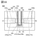
- FIG. 1A is a top view of a semiconductor device which is one embodiment of the present invention.
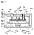
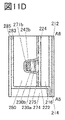
- 1B to 1D are cross-sectional views of semiconductor devices that are embodiments of the present invention.
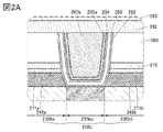
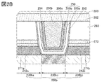
- 2A and 2B are cross-sectional views of a semiconductor device that is one embodiment of the present invention.
- FIG. 3 is a schematic cross-sectional view of a transistor used for calculation.
- 4A and 4B are diagrams showing calculation results.
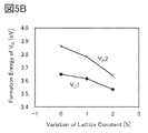
- FIG. 5A is a diagram showing the calculation model shown in this embodiment.
- FIG. 5B is a diagram showing the calculation results shown in this embodiment.
- 6A and 6B are cross-sectional views of a semiconductor device that is one embodiment of the present invention.
- 7A to 7D are schematic diagrams of aluminum concentration profiles in metal oxides.
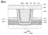
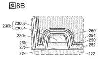
- FIG. 8A to 8C are cross-sectional views of semiconductor devices that are one embodiment of the present invention.
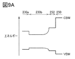
- 9A and 9B are diagrams showing band diagrams.
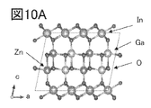
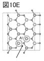
- 10A to 10E are diagrams showing the calculation model shown in this embodiment.
- FIG. 10F is a diagram showing the calculation results shown in this embodiment.
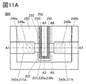
- FIG. 11A is a top view of a semiconductor device which is one embodiment of the present invention.
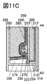
- 11B to 11D are cross-sectional views of semiconductor devices that are one embodiment of the present invention.
- FIG. 12A is a top view of a semiconductor device which is one embodiment of the present invention.
- 12B to 12D are cross-sectional views of semiconductor devices that are one embodiment of the present invention.
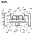
- FIG. 13A is a top view of a semiconductor device which is one embodiment of the present invention.
- FIG. 13B to 13D are cross-sectional views of semiconductor devices that are one embodiment of the present invention.
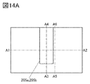
- FIG. 14A is a top view illustrating a method for manufacturing a semiconductor device which is one embodiment of the present invention.
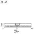
- 14B to 14D are cross-sectional views illustrating a method for manufacturing a semiconductor device which is one embodiment of the present invention.
- FIG. 15A is a top view illustrating a method for manufacturing a semiconductor device which is one embodiment of the present invention.
- 15B to 15D are cross-sectional views illustrating a method for manufacturing a semiconductor device which is one embodiment of the present invention.
- FIG. 16A is a top view illustrating a method for manufacturing a semiconductor device which is one embodiment of the present invention.
- FIG. 16B to 16D are cross-sectional views illustrating a method for manufacturing a semiconductor device which is one embodiment of the present invention.
- FIG. 17A is a top view illustrating a method for manufacturing a semiconductor device which is one embodiment of the present invention.
- 17B to 17D are cross-sectional views illustrating a method for manufacturing a semiconductor device which is one embodiment of the present invention.
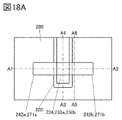
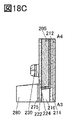
- FIG. 18A is a top view illustrating a method for manufacturing a semiconductor device which is one embodiment of the present invention.
- 18B to 18D are cross-sectional views illustrating a method for manufacturing a semiconductor device which is one embodiment of the present invention.
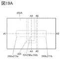
- FIG. 19A is a top view illustrating a method for manufacturing a semiconductor device which is one embodiment of the present invention.
- FIG. 19B to 19D are cross-sectional views illustrating a method for manufacturing a semiconductor device which is one embodiment of the present invention.
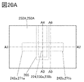
- FIG. 20A is a top view illustrating a method for manufacturing a semiconductor device which is one embodiment of the present invention.
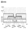
- 20B to 20D are cross-sectional views illustrating a method for manufacturing a semiconductor device which is one embodiment of the present invention.
- FIG. 21A is a top view illustrating a method for manufacturing a semiconductor device which is one embodiment of the present invention.
- 21B to 21D are cross-sectional views illustrating a method for manufacturing a semiconductor device which is one embodiment of the present invention.
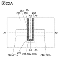
- FIG. 22A is a top view illustrating a method for manufacturing a semiconductor device which is one embodiment of the present invention.
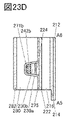
- FIG. 22B to 22D are cross-sectional views illustrating a method for manufacturing a semiconductor device which is one embodiment of the present invention.
- FIG. 23A is a top view illustrating a method for manufacturing a semiconductor device which is one embodiment of the present invention.
- 23B to 23D are cross-sectional views illustrating a method for manufacturing a semiconductor device which is one embodiment of the present invention.
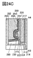
- FIG. 24A is a top view illustrating a method for manufacturing a semiconductor device which is one embodiment of the present invention.
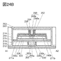
- 24B to 24D are cross-sectional views illustrating a method for manufacturing a semiconductor device which is one embodiment of the present invention.
- FIG. 25A is a top view illustrating a method for manufacturing a semiconductor device which is one embodiment of the present invention.
- FIG. 25B to 25D are cross-sectional views illustrating a method for manufacturing a semiconductor device which is one embodiment of the present invention.
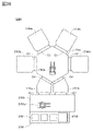
- FIG. 26 is a top view illustrating a microwave processing apparatus according to one embodiment of the present invention.
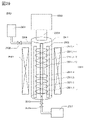
- FIG. 27 is a cross-sectional view illustrating a microwave processing device according to one aspect of the present invention.
- FIG. 28 is a cross-sectional view illustrating a microwave processing device according to one embodiment of the present invention.
- FIG. 29 is a cross-sectional view illustrating a microwave processing device according to one embodiment of the present invention.
- FIG. 30A is a plan view of a semiconductor device according to one embodiment of the present invention.
- 30B and 30C are cross-sectional views of a semiconductor device that is one embodiment of the present invention.
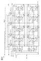
- FIG. 31 is a diagram showing a circuit diagram of a semiconductor device.
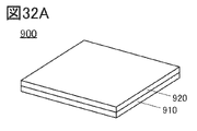
- FIG. 32A is a perspective view of a semiconductor device.
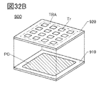
- FIG. 32B is a perspective view explaining the configuration of the semiconductor device.
- FIG. 33 is a cross-sectional view illustrating a structure of a memory device according to one embodiment of the present invention.
- FIG. 34 is a cross-sectional view illustrating a structure of a memory device according to one embodiment of the present invention.
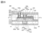
- FIG. 35 is a cross-sectional view of a semiconductor device according to one embodiment of the present invention.
- 36A and 36B are cross-sectional views of semiconductor devices according to one embodiment of the present invention.
- FIG. 37 is a cross-sectional view of a semiconductor device according to one embodiment of the present invention.
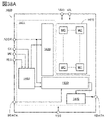
- FIG. 38A is a block diagram illustrating a configuration example of a memory device according to one embodiment of the present invention.
- FIG. 38B is a perspective view illustrating a configuration example of a memory device according to one embodiment of the present invention.
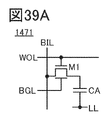
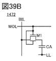
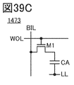
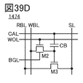
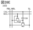
- 39A to 39H are circuit diagrams illustrating configuration examples of memory devices according to one embodiment of the present invention.
- 40A and 40B are schematic diagrams of a semiconductor device according to one embodiment of the present invention.
- 41A and 41B are diagrams illustrating an example of an electronic component.
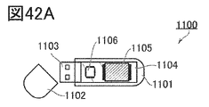
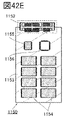
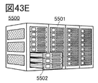
- 42A to 42E are schematic diagrams of a memory device according to one embodiment of the present invention.
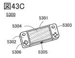
- 43A to 43H are diagrams illustrating electronic devices according to one embodiment of the present invention.
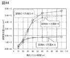
- FIG. 44 is a diagram for explaining the dependence of the oxygen release amount on the thickness of the silicon oxide film.
- FIG. 44 is a diagram for explaining the dependence of the oxygen release amount on the thickness of the silicon oxide film.
- FIG. 45A is a diagram illustrating a cross-sectional STEM image of an aluminum oxide film.
- FIG. 45B is a diagram for explaining the film thickness of the cross section of the aluminum oxide film.
- FIG. 46A is a diagram for explaining the laminated structure of the laminated film.
- FIG. 46B is the SIMS analysis result of the laminated film.
- FIG. 47A is a diagram explaining the structure of an aluminum oxide film.
- FIG. 47B is a diagram for explaining the aluminum oxide film structure dependence of the oxygen release amount.
- FIG. 48A is a cross-sectional STEM image of the sample produced in Example.
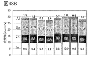
- Figures 48B and 48C are the results of EDX analysis of the samples produced in Examples.
- 49A to 49C are the results of SIMS analysis of samples produced in Examples.
- 50 is a diagram showing a top view, a cross-sectional TEM image, and parameters of the TEG produced in Example.
- 51A and 51B show the Id-Vg characteristics of the transistor manufactured in Example.
- 52A and 52B are Vth cumulative probability distributions of the transistors manufactured in Example.
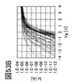
- 53A to 53C show the Id-Vg characteristics of the transistor manufactured in Example.
- 54A to 54C are Vth cumulative probability distributions of the transistors manufactured in Examples.
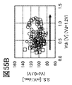
- 55A to 55C are diagrams showing the relationship between Vth and Id-Vg characteristics of transistors manufactured in Examples.
- FIG. 56A shows the Id-Vg characteristics of the transistor manufactured in Example.
- FIG. 56B is the Vth cumulative probability distribution of the transistor manufactured in Example.
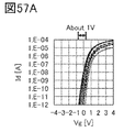
- FIG. 57A shows the Id-Vg characteristics of the transistor manufactured in Example.
- FIG. 57B is the Vth cumulative probability distribution of the transistor manufactured in Example.
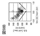
- 58A to 58C are diagrams showing the relationship between Vth and Id-Vg characteristics of transistors manufactured in Examples.
- 59A1 to 59C2 are cross-sectional TEM images obtained in Example.
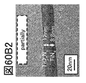
- 60A1 to 60B2 are cross-sectional TEM images obtained in Example.
- FIG. 61 is a diagram for explaining the film thickness of each film before heat treatment and the film thickness of each film after heat treatment.
- FIG. 62A is a diagram explaining the laminated structure of the sample.
- FIG. 62B is a diagram for explaining the sheet resistance of metal oxide.
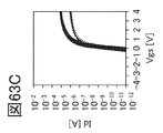
- FIG. 64A to 63C show the Id-Vg characteristics of the transistors manufactured in Examples.
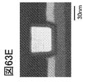
- 63D to 63F are cross-sectional TEM images of the transistor manufactured in Example.
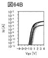
- 64A and 64B are the Id-Vg characteristics of the transistor.
- FIG. 64C is a schematic cross-sectional view of a transistor manufactured in Example.
- FIG. 65 is a diagram for explaining the stress of the conductor formed in the example.
- FIG. 66 is a diagram for explaining the relationship between Ion and stress of a transistor.
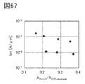
- FIG. 67 is a diagram for explaining the relationship between the ratio of the area of the channel forming region to the area of the source electrode or the drain electrode and the on current.
- FIG. 68A is a diagram explaining the laminated structure of the sample.
- FIG. 68B is a diagram explaining the results of SIMS analysis.
- FIG. 69A is the Id-Vg characteristic of the transistor.
- FIG. 69B is a schematic diagram of oxygen supply to metal oxide.
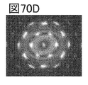
- 70A and 70B are planar TEM images of metal oxides.
- 70C and 70D are FFT images.
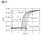
- FIG. 71 shows the Id-Vg characteristics of the transistor manufactured in Example.
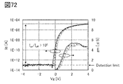
- FIG. 72 shows the Id-Vg characteristics of the transistor manufactured in Example.
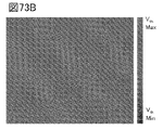
- 73A and 73B are Vth maps of transistors.
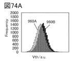
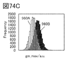
- 74A-74D are histograms of Vth, S value, gm, and Ion of the transistor.
- FIG. 75A is a schematic diagram showing the structure of a prototype transistor.
- FIG. 75A is a schematic diagram showing the structure of a prototype transistor.
- 75B is a cross-sectional view of the prototyped transistor in the channel width direction.
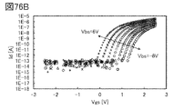
- 76A and 76B are diagrams showing the drain current-top gate voltage characteristics of the prototyped transistor.
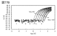
- 77A and 77B are diagrams showing the drain current-top gate voltage characteristics of the prototyped transistor.
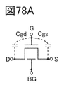
- 78A and 78B are diagrams for explaining capacitance.
- 78C and 78D are diagrams showing the top gate voltage-capacitance characteristics of the prototyped transistor.
- top views also called “plan views”
- perspective views descriptions of some components may be omitted in order to facilitate understanding of the invention. Also, description of some hidden lines may be omitted.
- the ordinal numbers such as first and second are used for convenience and do not indicate the order of steps or the order of stacking. Therefore, for example, “first” can be appropriately replaced with “second” or “third”. Also, the ordinal numbers described in this specification and the like may not match the ordinal numbers used to specify one aspect of the present invention.
- connection relationships other than the connection relationships shown in the drawings or the text are not limited to the predetermined connection relationships, for example, the connection relationships shown in the drawings or the text.
- X and Y are objects (for example, devices, elements, circuits, wiring, electrodes, terminals, conductive films, layers, etc.).
- a transistor is an element having at least three terminals including a gate, a drain, and a source.
- a region in which a channel is formed (hereinafter also referred to as a channel formation region) is provided between the drain (drain terminal, drain region, or drain electrode) and the source (source terminal, source region, or source electrode).
- a current can flow between the source and the drain through the formation region.
- a channel formation region means a region where current mainly flows.
- the function of the source or drain may be switched when using transistors of different polarities or when the direction of current changes in circuit operation. Therefore, in this specification and the like, the terms “source” and “drain” can be used interchangeably in some cases.
- the channel length is, for example, a region in which a semiconductor (or a portion of the semiconductor in which current flows when the transistor is on) overlaps with a gate electrode in a top view of a transistor, or the source length in a channel formation region.
- the channel length does not always have the same value in all regions of one transistor. That is, the channel length of one transistor may not be fixed to one value. Therefore, in this specification, the channel length is any one value, maximum value, minimum value, or average value in the channel forming region.
- the channel width is the region in which the semiconductor (or the portion of the semiconductor where current flows when the transistor is on) and the gate electrode overlap each other, or the channel length direction in the channel formation region.
- a channel width in a region where a channel is actually formed (hereinafter also referred to as an “effective channel width”) and a channel width shown in a top view of a transistor ( hereinafter also referred to as “apparent channel width”) may be different.
- the effective channel width becomes larger than the apparent channel width, and its influence cannot be ignored.
- the proportion of the channel formation region formed on the side surface of the semiconductor may be large. In that case, the effective channel width is larger than the apparent channel width.
- channel width may refer to the apparent channel width.
- channel width may refer to the effective channel width.
- the values of the channel length, channel width, effective channel width, apparent channel width, etc. can be determined by analyzing a cross-sectional TEM image or the like.
- impurities in a semiconductor refer to, for example, substances other than the main components that constitute the semiconductor.
- an element whose concentration is less than 0.1 atomic percent can be said to be an impurity.
- the inclusion of impurities may cause, for example, an increase in the defect level density of the semiconductor, a decrease in crystallinity, and the like.
- impurities that change the characteristics of the semiconductor include, for example, group 1 elements, group 2 elements, group 13 elements, group 14 elements, group 15 elements, and oxide semiconductors.
- transition metals other than the main component such as hydrogen, lithium, sodium, silicon, boron, phosphorus, carbon, and nitrogen.
- water may also function as an impurity.
- oxygen vacancies also referred to as V 2 O 3
- silicon oxynitride contains more oxygen than nitrogen as its composition.
- Silicon nitride oxide contains more nitrogen than oxygen in its composition.
- aluminum oxynitride has a higher content of oxygen than nitrogen as its composition.
- aluminum oxynitride has a composition in which the content of nitrogen is higher than that of oxygen.
- hafnium oxynitride has a higher content of oxygen than nitrogen as its composition.
- hafnium oxynitride has a composition in which the content of nitrogen is higher than that of oxygen.
- insulator can be replaced with an insulating film or an insulating layer.
- conductor can be replaced with a conductive film or a conductive layer.
- semiconductor can be interchanged with a semiconductor film or a semiconductor layer.
- parallel means a state in which two straight lines are arranged at an angle of -10 degrees or more and 10 degrees or less. Therefore, the case of ⁇ 5 degrees or more and 5 degrees or less is also included.
- substantially parallel means a state in which two straight lines are arranged at an angle of -30 degrees or more and 30 degrees or less.
- Perfect means that two straight lines are arranged at an angle of 80 degrees or more and 100 degrees or less. Therefore, the case of 85 degrees or more and 95 degrees or less is also included.
- substantially perpendicular means a state in which two straight lines are arranged at an angle of 60 degrees or more and 120 degrees or less.
- a metal oxide is a metal oxide in a broad sense.
- Metal oxides are classified into oxide insulators, oxide conductors (including transparent oxide conductors), oxide semiconductors (also referred to as oxide semiconductors or simply OSs), and the like.
- oxide semiconductors also referred to as oxide semiconductors or simply OSs
- an OS transistor can be referred to as a transistor including a metal oxide or an oxide semiconductor.
- the term “normally-off” means that the drain current per 1 ⁇ m of the channel width flowing through the transistor when no potential is applied to the gate or when a ground potential is applied to the gate is 1 ⁇ 10 ⁇ 1 at room temperature. 20 A or less, 1 ⁇ 10 ⁇ 18 A or less at 85° C., or 1 ⁇ 10 ⁇ 16 A or less at 125° C.
- Voltage is a potential difference from a reference potential.
- the reference potential is ground potential
- “voltage” can be replaced with “potential”. Note that the ground potential does not necessarily mean 0V.
- the potential is relative, and when the reference potential changes, the potential applied to the wiring, the potential applied to the circuit, etc., and the potential output from the circuit etc. also change.
- substantially the same height indicates a configuration in which the heights from a reference plane (for example, a flat plane such as a substrate surface) are equal in cross-sectional view.
- planarization processing typically CMP (Chemical Mechanical Polishing) processing
- CMP Chemical Mechanical Polishing
- the surfaces to be CMP-processed have the same height from the reference surface.
- approximately matching heights includes cases where the heights match.
- the heights of the layers may differ depending on the processing equipment, processing method, or material of the surface to be processed during the CMP processing.
- this case is also treated as "substantially the same height".
- the height of the top surface of the first layer and the height of the second layer When the difference from the height of the upper surface is 20 nm or less, it is also said that the heights are approximately the same.
- the side surfaces or the edges roughly match means that at least part of the outline overlaps between the upper layer and the lower layer when viewed from the top.
- the upper layer and the lower layer may be processed with the same mask pattern or partially with the same mask pattern.
- flat sides or edges roughly match includes the case where the sides or edges match.
- the contours do not overlap, and the upper contour may be positioned inside the lower contour, or the upper contour may be positioned outside the lower contour. The parts roughly match.”
- FIG. 1A-1D are top and cross-sectional views of a semiconductor device having a transistor 200.
- FIG. 1A is a top view of the semiconductor device.
- 1B to 1D are cross-sectional views of the semiconductor device.
- FIG. 1B is a cross-sectional view of the portion indicated by the dashed-dotted line A1-A2 in FIG. 1A, and is also a cross-sectional view of the transistor 200 in the channel length direction.
- FIG. 1C is a cross-sectional view of the portion indicated by the dashed-dotted line A3-A4 in FIG.
- FIG. 1A is also a cross-sectional view of the transistor 200 in the channel width direction.
- FIG. 1D is sectional drawing of the site
- a semiconductor device of one embodiment of the present invention includes an insulator 212 over a substrate (not shown), an insulator 214 over the insulator 212, a transistor 200 over the insulator 214, and an insulator 280 over the transistor 200. , insulator 282 on insulator 280 , insulator 283 on insulator 282 , insulator 274 on insulator 283 , insulator 285 on insulator 283 and insulator 274 .
- the insulator 212, the insulator 214, the insulator 216, the insulator 280, the insulator 282, the insulator 283, the insulator 285, and the insulator 274 function as interlayer films.
- conductor 240 (a conductor 240a and a conductor 240b) that is electrically connected to the transistor 200 and functions as a plug.
- insulators 241 (insulators 241a and 241b) are provided in contact with side surfaces of conductors 240 functioning as plugs.
- conductors 246 (conductors 246 a and 246 b ) that are electrically connected to the conductor 240 and function as wirings are provided over the insulator 285 and the conductor 240 .
- the insulator 283 is in contact with part of the top surface of the insulator 214, the side surface of the insulator 216, the side surface of the insulator 222, the side surface of the insulator 275, the side surface of the insulator 280, and the side surface and top surface of the insulator 282. .
- An insulator 241a is provided in contact with the inner wall of the opening of the insulator 280, the insulator 282, the insulator 283, and the insulator 285, and the conductor 240a is provided in contact with the side surface of the insulator 241a.
- An insulator 241b is provided in contact with the inner wall of the opening of the insulator 280, the insulator 282, the insulator 283, and the insulator 285, and the conductor 240b is provided in contact with the side surface of the insulator 241b.
- the insulator 241 has a structure in which a first insulator is provided in contact with the inner wall of the opening, and a second insulator is provided inside.
- the conductor 240 has a structure in which a first conductor is provided in contact with the side surface of the insulator 241 and a second conductor is provided inside.
- the height of the top surface of the conductor 240 and the height of the top surface of the insulator 285 in the region overlapping with the conductor 246 are approximately the same.
- the transistor 200 shows a structure in which the first insulator of the insulator 241 and the second insulator of the insulator 241 are stacked, the present invention is not limited to this.
- the insulator 241 may be provided as a single layer or a stacked structure of three or more layers.
- the transistor 200 shows the structure in which the first conductor of the conductor 240 and the second conductor of the conductor 240 are stacked, the present invention is not limited to this.
- the conductor 240 may be provided as a single layer or a laminated structure of three or more layers. When the structure has a laminated structure, an ordinal number may be assigned in order of formation for distinction.
- the transistor 200 includes an insulator 216 over the insulator 214, conductors 205 (a conductor 205a and a conductor 205b) embedded in the insulator 216, and an insulating material.
- the insulator 252 includes the top surface of the insulator 222, the sides of the insulator 224, the sides of the oxide 230a, the sides and top of the oxide 230b, the sides of the conductor 242, It contacts the side surface of the insulator 271 , the side surface of the insulator 275 , the side surface of the insulator 280 , and the bottom surface of the insulator 250 .
- the top surface of the conductor 260 is arranged so that the top surface of the insulator 254 , the top surface of the insulator 250 , the top surface of the insulator 252 , and the top surface of the insulator 280 are substantially flush with each other.
- the insulator 282 is in contact with at least part of the upper surface of each of the conductor 260 , the insulator 252 , the insulator 250 , the insulator 254 , and the insulator 280 .
- oxide 230a and the oxide 230b may be collectively referred to as the oxide 230 below.
- the conductor 242a and the conductor 242b are collectively referred to as the conductor 242 in some cases.
- the insulator 271a and the insulator 271b are collectively referred to as the insulator 271 .
- the insulator 280 and the insulator 275 are provided with openings reaching the oxide 230b.
- An insulator 252, an insulator 250, an insulator 254, and a conductor 260 are positioned within the opening.
- a conductor 260, an insulator 252, an insulator 250, and an insulator 254 are provided between the insulator 271a and the conductor 242a and the insulator 271b and the conductor 242b.
- the insulator 254 has a region in contact with the side surface of the conductor 260 and a region in contact with the bottom surface of the conductor 260 .
- the oxide 230 preferably has an oxide 230a overlying the insulator 224 and an oxide 230b overlying the oxide 230a.
- the transistor 200 has a structure in which the oxide 230 has two layers of the oxide 230a and the oxide 230b stacked, the present invention is not limited to this.
- a single layer of the oxide 230b or a layered structure of three or more layers may be provided, or each of the oxides 230a and 230b may have a layered structure.
- the conductor 260 functions as a first gate (also called top gate) electrode, and the conductor 205 functions as a second gate (also called back gate) electrode.
- insulators 252, 250, and 254 function as a first gate insulator
- insulators 222 and 224 function as a second gate insulator.
- the gate insulator is sometimes called a gate insulating layer or a gate insulating film.
- the conductor 242a functions as one of the source electrode and the drain electrode
- the conductor 242b functions as the other of the source electrode and the drain electrode. At least part of the region of the oxide 230 overlapping with the conductor 260 functions as a channel formation region.
- FIG. 2A shows an enlarged view of the vicinity of the channel forming region in FIG. 1B.
- the oxide 230b includes a region 230bc functioning as a channel formation region of the transistor 200, and regions 230ba and 230bb functioning as a source region or a drain region and provided to sandwich the region 230bc.
- the region 230bc overlaps the conductor 260 .
- the region 230bc is provided in a region between the conductors 242a and 242b.
- the region 230ba is provided so as to overlap with the conductor 242a
- the region 230bb is provided so as to overlap with the conductor 242b.
- region 230bc functioning as a channel forming region is a high-resistance region with a lower carrier concentration because it has less oxygen vacancies or a lower impurity concentration than the regions 230ba and 230bb.
- region 230bc can be said to be i-type (intrinsic) or substantially i-type.
- the region 230ba and the region 230bb functioning as a source region or a drain region have many oxygen vacancies or have a high impurity concentration such as hydrogen, nitrogen, or a metal element, so that the carrier concentration is increased and the resistance is lowered.
- the regions 230ba and 230bb are n-type regions having a higher carrier concentration and a lower resistance than the region 230bc.
- the carrier concentration of the region 230bc functioning as a channel formation region is preferably 1 ⁇ 10 18 cm ⁇ 3 or less, more preferably less than 1 ⁇ 10 17 cm ⁇ 3 , and 1 ⁇ 10 16 cm It is more preferably less than ⁇ 3 , more preferably less than 1 ⁇ 10 13 cm ⁇ 3 , even more preferably less than 1 ⁇ 10 12 cm ⁇ 3 .
- the lower limit of the carrier concentration of the region 230bc functioning as a channel forming region is not particularly limited, but can be, for example, 1 ⁇ 10 ⁇ 9 cm ⁇ 3 .
- the carrier concentration is equal to or lower than the carrier concentration of the region 230ba and the region 230bb, and equal to or higher than the carrier concentration of the region 230bc.
- a region may be formed. That is, the region functions as a junction region between the region 230bc and the region 230ba or the region 230bb.
- the bonding region may have a hydrogen concentration equal to or lower than that of the regions 230ba and 230bb and equal to or higher than that of the region 230bc.
- the bonding region may have oxygen vacancies equal to or less than those of the regions 230ba and 230bb and equal to or greater than those of the region 230bc.
- FIG. 2A shows an example in which the regions 230ba, 230bb, and 230bc are formed in the oxide 230b
- the present invention is not limited to this.
- each of the above regions may be formed up to oxide 230a as well as oxide 230b.
- the concentrations of metal elements and impurity elements such as hydrogen and nitrogen detected in each region are not limited to stepwise changes for each region, and may change continuously within each region. In other words, the closer the region is to the channel formation region, the lower the concentrations of the metal elements and the impurity elements such as hydrogen and nitrogen.
- a metal oxide functioning as a semiconductor (hereinafter also referred to as an oxide semiconductor) is preferably used for the oxide 230 (the oxide 230a and the oxide 230b) including a channel formation region.
- the bandgap of the metal oxide that functions as a semiconductor is preferably 2 eV or more, more preferably 2.5 eV or more.
- the off-state current of the transistor can be reduced by using a metal oxide with a large bandgap.
- an In-M-Zn oxide containing indium, element M and zinc (element M is aluminum, gallium, yttrium, tin, copper, vanadium, beryllium, boron, titanium, iron, nickel, germanium , zirconium, molybdenum, lanthanum, cerium, neodymium, hafnium, tantalum, tungsten, or magnesium).
- element M is aluminum, gallium, yttrium, tin, copper, vanadium, beryllium, boron, titanium, iron, nickel, germanium , zirconium, molybdenum, lanthanum, cerium, neodymium, hafnium, tantalum, tungsten, or magnesium.
- an In--Ga oxide, an In--Zn oxide, or an indium oxide may be used.
- the oxide 230 preferably has a laminated structure of multiple oxide layers with different chemical compositions.
- the atomic ratio of the element M to the main component metal element is the same as the atomic ratio of the element M to the main component metal element in the metal oxide used for the oxide 230b. Larger is preferable.
- the atomic ratio of the element M to In is preferably higher than the atomic ratio of the element M to In in the metal oxide used for the oxide 230b. With this structure, diffusion of impurities and oxygen from structures formed below the oxide 230a to the oxide 230b can be suppressed.
- the atomic ratio of In to the element M is preferably higher than the atomic ratio of In to the element M in the metal oxide used for the oxide 230a.
- the transistor 200 can have high on-state current and high frequency characteristics.
- the oxides 230a and 230b have a common element other than oxygen as a main component, the defect level density at the interface between the oxides 230a and 230b can be reduced. Since the defect level density at the interface between the oxides 230a and 230b can be reduced, the effect of interface scattering on carrier conduction is small, and a high on-current can be obtained.
- the neighboring composition includes a range of ⁇ 30% of the desired atomic number ratio.
- the element M it is preferable to use gallium.
- a metal oxide that can be used for the oxide 230a may be used as the oxide 230b.
- the above atomic ratio is not limited to the atomic ratio of the deposited metal oxide, and the atomic ratio of the sputtering target used for the deposition of the metal oxide. may be
- the oxide 230b preferably has crystallinity.
- CAAC-OS c-axis aligned crystal oxide semiconductor
- CAAC-OS is a metal oxide that has a dense structure with high crystallinity and few impurities and defects (eg, oxygen vacancies (V 2 O 3 ) and the like).
- heat treatment is performed at a temperature at which the metal oxide does not become polycrystalline (for example, 400° C. or higher and 600° C. or lower), so that the CAAC-OS has a dense structure with higher crystallinity.
- a temperature at which the metal oxide does not become polycrystalline for example, 400° C. or higher and 600° C. or lower
- the oxide 230b by using a crystalline oxide such as CAAC-OS as the oxide 230b, extraction of oxygen from the oxide 230b by the source electrode or the drain electrode can be suppressed. Accordingly, extraction of oxygen from the oxide 230b can be reduced even if heat treatment is performed, so that the transistor 200 is stable against high temperatures (so-called thermal budget) in the manufacturing process.
- a crystalline oxide such as CAAC-OS
- a transistor including an oxide semiconductor if impurities and oxygen vacancies are present in a region where a channel is formed in the oxide semiconductor, electrical characteristics are likely to vary, and reliability may be degraded.
- hydrogen in the vicinity of oxygen vacancies may form defects in which hydrogen enters oxygen vacancies (hereinafter sometimes referred to as V OH ) to generate electrons serving as carriers. Therefore, if oxygen vacancies are included in the region where the channel is formed in the oxide semiconductor, the transistor has normally-on characteristics (the channel exists even if no voltage is applied to the gate electrode, and current flows through the transistor). flow characteristics). Therefore, impurities, oxygen vacancies, and VOH are preferably reduced as much as possible in a region where a channel is formed in the oxide semiconductor. In other words, the region in which the channel is formed in the oxide semiconductor preferably has a reduced carrier concentration and is i-type (intrinsic) or substantially i-type.
- an insulator containing oxygen that is released by heating (hereinafter sometimes referred to as excess oxygen) is provided in the vicinity of the oxide semiconductor, and heat treatment is performed so that the oxide semiconductor is converted from the insulator.
- Oxygen can be supplied and oxygen vacancies and VOH can be reduced.
- the on-state current or the field-effect mobility of the transistor 200 might decrease.
- variations in the amount of oxygen supplied to the source region or the drain region within the substrate surface cause variations in the characteristics of the semiconductor device having transistors.
- the region 230bc functioning as a channel formation region preferably has a reduced carrier concentration and is i-type or substantially i-type.
- Region 230bb has a high carrier concentration and is preferably n-type. In other words, it is preferable to reduce oxygen vacancies and VOH in the region 230bc of the oxide semiconductor and prevent an excessive amount of oxygen from being supplied to the regions 230ba and 230bb .
- the region 230ba and the region 230bb functioning as a source region or a drain region preferably have a high carrier concentration and are n-type.
- the concentration is reduced and is i-type or substantially i-type.
- the n-type region preferably does not extend into the channel forming region.
- the device simulation was performed using Synopsys TCAD Sentaurus.
- a schematic cross-sectional view of a transistor used for the device simulation is shown in FIG.
- the transistor includes an oxide semiconductor (OS), a source electrode (Source) and a drain electrode (Drain) over the oxide semiconductor, and a gate electrode (Gate) overlapping with the oxide semiconductor.
- OS oxide semiconductor
- Source source electrode
- Drain drain electrode
- Gate gate electrode
- LSD shown in FIG. 3 is the distance between the source and drain electrodes.
- ⁇ L shown in FIG. 3 is the length of the n-type region extending from the end of the source or drain electrode to the channel formation region.
- LSD was set to 60 nm, 120 nm, or 240 nm.
- ⁇ L was set to 0 nm, 5 nm, 10 nm, 20 nm, or 30 nm.
- the donor concentration Nd of the source region, the drain region, and the n -type region was set to 1 ⁇ 10 19 cm ⁇ 3 or 5 ⁇ 10 19 cm ⁇ 3 .
- the channel width was set to 60 nm.
- FIGS. 4A and 4B The device simulation results are shown in FIGS. 4A and 4B.
- FIG. 4A shows the results when the donor concentration Nd of the source region, the drain region, and the n -type region is 1 ⁇ 10 19 cm ⁇ 3
- FIG. This is the result when the donor concentration Nd of the region is 5 ⁇ 10 19 cm ⁇ 3 .
- the vertical axis indicates the amount of change in threshold voltage ( ⁇ Vth) [V], and the horizontal axis indicates ⁇ L [nm].
- the threshold voltage (Vth) is defined as the gate voltage Vg when the drain current becomes 1 pA.
- the plots indicated by circles are the results when the LSD is 240 nm
- the plots indicated by squares are the results when the LSD is 120 nm
- the plots indicated by diamonds are the LSD . These are the results when the thickness is set to 60 nm.
- the n-type region preferably does not extend into the channel forming region.
- microwave treatment is performed in an atmosphere containing oxygen with the conductors 242a and 242b provided over the oxide 230b, so that oxygen vacancies in the region 230bc and VOH are reduced.
- the microwave treatment refers to treatment using an apparatus having a power supply for generating high-density plasma using microwaves, for example.
- oxygen gas By performing microwave treatment in an atmosphere containing oxygen, oxygen gas can be converted into plasma using microwaves or high frequencies such as RF, and the oxygen plasma can act. At this time, the region 230bc can also be irradiated with microwaves or high frequencies such as RF.
- V OH in the region 230bc is divided into oxygen vacancies (V 0 ) and hydrogen ( H ), the hydrogen is removed from the region 230bc, and the oxygen vacancies are compensated with oxygen. can be done. Therefore, the hydrogen concentration, oxygen vacancies, and VOH in the region 230bc can be reduced, and the carrier concentration can be lowered.
- the effects of microwaves, high frequencies such as RF, oxygen plasma, etc. are shielded by the conductors 242a and 242b and do not reach the regions 230ba and 230bb.
- the effect of oxygen plasma can be reduced by insulators 271 and 280 provided over oxide 230b and conductor 242.
- FIG. 1 V OH is reduced and an excessive amount of oxygen is not supplied in the regions 230ba and 230bb during the microwave treatment, so that a decrease in carrier concentration can be prevented.
- microwave treatment is preferably performed in an oxygen-containing atmosphere.
- an atmosphere containing oxygen By performing microwave treatment in an atmosphere containing oxygen through the insulator 252 or the insulator 250 in this manner, oxygen can be efficiently injected into the region 230bc.
- the insulator 252 so as to be in contact with the side surface of the conductor 242 and the surface of the region 230bc, it is possible to suppress the injection of more than a necessary amount of oxygen into the region 230bc and suppress the oxidation of the side surface of the conductor 242. .
- oxidation of the side surface of the conductor 242 can be suppressed when the insulating film to be the insulator 250 is formed.
- the oxygen injected into the region 230bc has various forms such as oxygen atoms, oxygen molecules, and oxygen radicals (also called O radicals, atoms, molecules, or ions having unpaired electrons).
- the oxygen injected into the region 230bc may be one or more of the above forms, and oxygen radicals are particularly preferable.
- the film quality of the insulator 252 and the insulator 250 can be improved, the reliability of the transistor 200 is improved.
- oxygen vacancies and V OH can be selectively removed from the oxide semiconductor region 230bc to make the region 230bc i-type or substantially i-type. Furthermore, excessive supply of oxygen to the regions 230ba and 230bb functioning as the source region or the drain region can be suppressed, and the state of the n-type region before the microwave treatment can be maintained. As a result, variations in the electrical characteristics of the transistor 200 can be suppressed, and variation in the electrical characteristics of the transistor 200 within the substrate surface can be suppressed.
- a semiconductor device with little variation in transistor characteristics can be provided by adopting the configuration described above. Moreover, a highly reliable semiconductor device can be provided. Moreover, a semiconductor device having favorable electrical characteristics can be provided.
- a curved surface may be provided between the side surface of the oxide 230b and the top surface of the oxide 230b in a cross-sectional view of the transistor 200 in the channel width direction. That is, the end of the side surface and the end of the upper surface may be curved (hereinafter also referred to as round shape).
- the radius of curvature of the curved surface is preferably larger than 0 nm and smaller than the film thickness of the oxide 230b in the region overlapping with the conductor 242, or smaller than half the length of the region without the curved surface.
- the radius of curvature of the curved surface is greater than 0 nm and less than or equal to 20 nm, preferably greater than or equal to 1 nm and less than or equal to 15 nm, and more preferably greater than or equal to 2 nm and less than or equal to 10 nm.
- the interface between the oxide 230 and the insulator 252 and its vicinity can be Indium contained in the oxide 230 may be unevenly distributed.
- the vicinity of the surface of the oxide 230 has an atomic ratio close to that of indium oxide or an atomic ratio close to that of In—Zn oxide.
- the defect level density at the interface between the oxide 230a and the oxide 230b can be reduced. Therefore, the influence of interface scattering on carrier conduction is reduced, and the transistor 200 can obtain a large on-current and high frequency characteristics.
- At least one of the insulator 212 , the insulator 214 , the insulator 271 , the insulator 275 , the insulator 282 , the insulator 283 , and the insulator 285 is exposed to impurities such as water and hydrogen from the substrate side or the transistor 200 . It preferably functions as a barrier insulating film that suppresses diffusion from above into the transistor 200 .
- At least one of the insulators 212, 214, 271, 275, 282, 283, and 285 is a hydrogen atom, a hydrogen molecule, a water molecule, a nitrogen atom, a nitrogen molecule, It is preferable to use an insulating material that has a function of suppressing the diffusion of impurities such as nitrogen oxide molecules (N 2 O, NO, NO 2 , etc.) and copper atoms (thus, the above impurities hardly permeate). Alternatively, it is preferable to use an insulating material that has a function of suppressing the diffusion of oxygen (eg, at least one of oxygen atoms, oxygen molecules, and the like) (the oxygen hardly permeates).
- an insulating material that has a function of suppressing the diffusion of oxygen eg, at least one of oxygen atoms, oxygen molecules, and the like
- a barrier insulating film refers to an insulating film having barrier properties.
- barrier property refers to the function of suppressing the diffusion of the corresponding substance (also referred to as “low permeability”).
- the corresponding substance has the function of capturing and fixing (also called gettering).
- the insulators 212, 214, 271, 275, 282, 283, and 285 are insulators having a function of suppressing diffusion of water, impurities such as hydrogen, and oxygen. is preferably used, and for example, aluminum oxide, magnesium oxide, hafnium oxide, gallium oxide, indium gallium zinc oxide, silicon nitride, or silicon nitride oxide can be used.
- the insulator 212, the insulator 275, and the insulator 283 are preferably made of silicon nitride or the like, which has a higher hydrogen barrier property.
- the insulator 214, the insulator 271, the insulator 282, and the insulator 285 are preferably made of aluminum oxide, magnesium oxide, or the like, which has high functions of capturing and fixing hydrogen.
- impurities such as water and hydrogen can be prevented from diffusing from the substrate side to the transistor 200 side through the insulators 212 and 214 .
- impurities such as water and hydrogen can be prevented from diffusing toward the transistor 200 from an interlayer insulating film or the like arranged outside the insulator 285 .
- diffusion of oxygen contained in the insulator 224 or the like to the substrate side through the insulators 212 and 214 can be suppressed.
- oxygen contained in the insulator 280 or the like can be prevented from diffusing above the transistor 200 through the insulator 282 or the like.
- the transistor 200 is formed of the insulators 212, 214, 271, 275, 282, 283, and 283, which have a function of suppressing diffusion of water, impurities such as hydrogen, and oxygen.
- a structure surrounded by an insulator 285 is preferable.
- the insulators 212, 214, 271, 275, 282, 283, and 285 are preferably oxides having an amorphous structure.
- metal oxides such as AlO x (x is any number greater than 0) or MgO y (y is any number greater than 0).
- Oxygen atoms in metal oxides having such an amorphous structure have dangling bonds, and the dangling bonds sometimes have the property of capturing or fixing hydrogen.
- hydrogen contained in the transistor 200 or hydrogen existing around the transistor 200 is captured or fixed. be able to.
- the transistor 200 and the semiconductor device with favorable characteristics and high reliability can be manufactured.
- the insulators 212, 214, 271, 275, 282, 283, and 285 preferably have an amorphous structure, but part of the insulator 212, the insulator 214, the insulator 271, the insulator 275, the insulator 282, the insulator 283, and the insulator 285 has a polycrystalline structure. may be formed.
- the insulator 212, the insulator 214, the insulator 271, the insulator 275, the insulator 282, the insulator 283, and the insulator 285 are multilayers in which a layer having an amorphous structure and a layer having a polycrystalline structure are stacked. It may be a structure. For example, a laminated structure in which a layer of polycrystalline structure is formed on a layer of amorphous structure may be used.
- the insulators 212, 214, 271, 275, 282, 283, and 285 may be deposited by sputtering, for example. Since the sputtering method does not require the use of molecules containing hydrogen in the deposition gas, the hydrogen concentrations of the insulators 212, 214, 271, 275, 282, 283, and 285 are can be reduced.
- the film formation method is not limited to the sputtering method, chemical vapor deposition (CVD) method, molecular beam epitaxy (MBE) method, pulsed laser deposition (PLD) method. ) method, Atomic Layer Deposition (ALD) method, or the like may be used as appropriate.
- insulators 212, 275, and 283 It may also be desirable to reduce the resistivity of insulators 212, 275, and 283.
- the resistivity of the insulator 212, the insulator 275, and the insulator 283 can be approximately 1 ⁇ 10 13 ⁇ cm, the insulator 212, the insulator 275, and the insulator 283 can be processed using plasma or the like in a manufacturing process of a semiconductor device. Insulator 283 can mitigate charge-up in conductor 205, conductor 242, conductor 260, or conductor 246 in some cases.
- Each of the insulator 212, the insulator 275, and the insulator 283 preferably has a resistivity of 1 ⁇ 10 10 ⁇ cm or more and 1 ⁇ 10 15 ⁇ cm or less.
- the insulator 216, the insulator 274, the insulator 280, and the insulator 285 preferably have a lower dielectric constant than the insulator 214.
- the parasitic capacitance generated between wirings can be reduced.
- the insulator 216, the insulator 274, the insulator 280, and the insulator 285 include silicon oxide, silicon oxynitride, silicon oxide to which fluorine is added, silicon oxide to which carbon is added, silicon oxide to which carbon and nitrogen are added, Silicon oxide having vacancies or the like may be used as appropriate.
- the conductor 205 is arranged so as to overlap with the oxide 230 and the conductor 260 .
- the conductor 205 is preferably embedded in an opening formed in the insulator 216 . Also, part of the conductor 205 is embedded in the insulator 214 in some cases.
- the conductor 205 has a conductor 205a and a conductor 205b.
- Conductor 205 a is provided in contact with the bottom and side walls of the opening formed in insulator 216 .
- the conductor 205b is provided so as to be embedded in a recess formed in the conductor 205a.
- the height of the top surface of the conductor 205b approximately matches the height of the top surface of the conductor 205a and the height of the top surface of the insulator 216 .
- the conductor 205a has a function of suppressing diffusion of impurities such as hydrogen atoms, hydrogen molecules, water molecules, nitrogen atoms, nitrogen molecules, nitrogen oxide molecules (such as N 2 O, NO, NO 2 ), and copper atoms. It is preferable to use a conductive material having a Alternatively, a conductive material having a function of suppressing diffusion of oxygen (eg, at least one of oxygen atoms and oxygen molecules) is preferably used.
- the conductor 205a By using a conductive material having a function of reducing diffusion of hydrogen for the conductor 205a, impurities such as hydrogen contained in the conductor 205b are prevented from diffusing into the oxide 230 through the insulator 224 or the like. can be prevented. In addition, by using a conductive material having a function of suppressing diffusion of oxygen for the conductor 205a, it is possible to suppress a decrease in conductivity due to oxidation of the conductor 205b. As the conductive material having a function of suppressing diffusion of oxygen, titanium, titanium nitride, tantalum, tantalum nitride, ruthenium, ruthenium oxide, or the like is preferably used, for example. Therefore, the conductor 205a may be a single layer or a laminate of the above conductive materials. For example, the conductor 205a may be titanium nitride.
- a conductive material containing tungsten, copper, or aluminum as its main component is preferably used for the conductor 205b.
- tungsten may be used for the conductor 205b.
- the conductor 205 may function as a second gate electrode.
- the threshold voltage (Vth) of the transistor 200 can be controlled by changing the potential applied to the conductor 205 independently of the potential applied to the conductor 260 .
- Vth of the transistor 200 can be increased and off-state current can be reduced. Therefore, applying a negative potential to the conductor 205 can make the drain current smaller when the potential applied to the conductor 260 is 0 V than when no potential is applied.
- the electric resistivity of the conductor 205 is designed in consideration of the potential applied to the conductor 205, and the film thickness of the conductor 205 is set according to the electric resistivity. Also, the thickness of the insulator 216 is almost the same as that of the conductor 205 . Here, it is preferable to reduce the film thickness of the conductor 205 and the insulator 216 within the range allowed by the design of the conductor 205 . By reducing the thickness of the insulator 216, the absolute amount of impurities such as hydrogen contained in the insulator 216 can be reduced;
- the conductor 205 is preferably provided larger than a region of the oxide 230 that does not overlap with the conductors 242a and 242b, as shown in FIG. 1A.
- the conductor 205 preferably extends also in regions outside the ends of the oxides 230a and 230b in the channel width direction.
- the conductor 205 and the conductor 260 preferably overlap with each other with an insulator interposed therebetween on the outside of the side surface of the oxide 230 in the channel width direction.
- the electric field of the conductor 260 functioning as the first gate electrode and the electric field of the conductor 205 functioning as the second gate electrode electrically surround the channel formation region of the oxide 230 .
- a transistor structure in which a channel formation region is electrically surrounded by electric fields of a first gate and a second gate is referred to as a surrounded channel (S-channel) structure.
- a transistor with an S-channel structure represents a transistor structure in which a channel formation region is electrically surrounded by electric fields of one and the other of a pair of gate electrodes.
- the S-channel structure disclosed in this specification and the like is different from the Fin type structure and the planar type structure.
- the transistor can have increased resistance to the short channel effect, in other words, a transistor in which the short channel effect is less likely to occur.
- the transistor 200 By setting the transistor 200 to be normally off and having the above S-channel structure, the channel formation region can be electrically surrounded. Therefore, the transistor 200 can also be regarded as having a GAA (Gate All Around) structure or an LGAA (Lateral Gate All Around) structure.
- GAA Gate All Around
- LGAA Layer Advanced Gate All Around
- a channel formation region formed at or near the interface between the oxide 230 and the gate insulator is the entire bulk of the oxide 230. can be done. Therefore, since the density of the current flowing through the transistor can be increased, it can be expected that the on-state current of the transistor or the field-effect mobility of the transistor can be increased.
- the conductor 205 is extended to function as wiring.
- a structure in which a conductor functioning as a wiring is provided under the conductor 205 may be employed.
- one conductor 205 does not necessarily have to be provided for each transistor.
- the conductor 205 may be shared by a plurality of transistors.
- the conductor 205 has a structure in which the conductor 205a and the conductor 205b are stacked; however, the present invention is not limited to this.
- the conductor 205 may be provided as a single layer or a laminated structure of three or more layers.
- the insulator 222 and the insulator 224 function as gate insulators.
- the insulator 222 preferably has a function of suppressing diffusion of hydrogen (for example, at least one of hydrogen atoms and hydrogen molecules). Further, the insulator 222 preferably has a function of suppressing diffusion of oxygen (eg, at least one of oxygen atoms, oxygen molecules, and the like). For example, the insulator 222 preferably has a function of suppressing diffusion of one or both of hydrogen and oxygen more than the insulator 224 does.
- hydrogen for example, at least one of hydrogen atoms and hydrogen molecules
- oxygen eg, at least one of oxygen atoms, oxygen molecules, and the like.
- the insulator 222 preferably has a function of suppressing diffusion of one or both of hydrogen and oxygen more than the insulator 224 does.
- the insulator 222 it is preferable to use an insulator containing oxides of one or both of aluminum and hafnium, which are insulating materials.
- the insulator aluminum oxide, hafnium oxide, an oxide containing aluminum and hafnium (hafnium aluminate), or the like is preferably used.
- the conductor 205 can be prevented from reacting with oxygen contained in the insulator 224 and the oxide 230 .
- aluminum oxide, bismuth oxide, germanium oxide, niobium oxide, silicon oxide, titanium oxide, tungsten oxide, yttrium oxide, or zirconium oxide may be added to the insulator.
- these insulators may be nitrided.
- these insulators may be stacked with silicon oxide, silicon oxynitride, or silicon nitride.
- the insulator 222 may be a single layer or a stack of insulators containing so-called high-k materials such as aluminum oxide, hafnium oxide, tantalum oxide, zirconium oxide, and hafnium zirconium oxide.
- high-k materials such as aluminum oxide, hafnium oxide, tantalum oxide, zirconium oxide, and hafnium zirconium oxide.
- thinning of gate insulators may cause problems such as leakage current.
- the gate potential during transistor operation can be reduced while maintaining the physical film thickness.
- a substance with a high dielectric constant such as lead zirconate titanate (PZT), strontium titanate (SrTiO 3 ), (Ba, Sr)TiO 3 (BST) may be used in some cases.
- silicon oxide, silicon oxynitride, or the like may be used as appropriate.
- the heat treatment may be performed at, for example, 100° C. to 600° C., more preferably 350° C. to 550° C.
- the heat treatment is performed in a nitrogen gas atmosphere, an inert gas atmosphere, or an atmosphere containing 10 ppm or more, 1% or more, or 10% or more of an oxidizing gas.
- heat treatment is preferably performed in an oxygen atmosphere. Accordingly, oxygen can be supplied to the oxide 230 to reduce oxygen vacancies.
- the heat treatment may be performed in an atmosphere containing 10 ppm or more, 1% or more, or 10% or more of an oxidizing gas in order to compensate for desorbed oxygen after the heat treatment is performed in a nitrogen gas or inert gas atmosphere. good.
- heat treatment may be continuously performed in a nitrogen gas or inert gas atmosphere.
- oxygen vacancies in the oxide 230 can be repaired with supplied oxygen. Furthermore, the supplied oxygen reacts with the hydrogen remaining in the oxide 230, so that the hydrogen can be removed as H 2 O (dehydrated). This can suppress recombination of hydrogen remaining in the oxide 230 with oxygen vacancies to form VOH.
- the insulator 222 and the insulator 224 may have a laminated structure of two or more layers. In that case, it is not limited to a laminated structure made of the same material, and a laminated structure made of different materials may be used.
- the insulator 224 may be formed in an island shape so as to overlap with the oxide 230a. In this case, the insulator 275 is in contact with the side surface of the insulator 224 and the top surface of the insulator 222 .
- an island shape means a state in which two or more layers formed in the same process and using the same material are physically separated.
- a conductor 242a and a conductor 242b are provided in contact with the top surface of the oxide 230b.
- the conductors 242a and 242b function as the source and drain electrodes of the transistor 200, respectively.
- Examples of the conductor 242 include nitride containing tantalum, nitride containing titanium, nitride containing molybdenum, nitride containing tungsten, nitride containing tantalum and aluminum, and titanium. and a nitride containing aluminum is preferably used.
- nitrides containing tantalum are particularly preferred.
- ruthenium oxide, ruthenium nitride, an oxide containing strontium and ruthenium, an oxide containing lanthanum and nickel, or the like may be used. These materials are preferable because they are conductive materials that are difficult to oxidize or materials that maintain conductivity even after absorbing oxygen.
- hydrogen contained in the oxide 230b and the like might diffuse into the conductor 242a or the conductor 242b.
- hydrogen contained in the oxide 230b or the like easily diffuses into the conductor 242a or the conductor 242b, and the diffused hydrogen 242a or the conductor 242b. That is, hydrogen contained in the oxide 230b or the like might be absorbed by the conductor 242a or the conductor 242b.
- the conductor 242 without the curved surface, the cross-sectional area of the conductor 242 in the cross section in the channel width direction as shown in FIG. 1D can be increased. Accordingly, the conductivity of the conductor 242 can be increased, and the on current of the transistor 200 can be increased.
- the sheet resistance of the oxide 230b in a region overlapping with the conductor 242a (the conductor 242b) is reduced.
- the carrier concentration may increase. Therefore, the resistance of the oxide 230b in the region overlapping with the conductor 242a (the conductor 242b) can be reduced in a self-aligning manner.
- the conductor 242 is preferably formed using a conductive film having compressive stress.
- a strain expanding in the direction of tension (hereinafter sometimes referred to as tensile strain) can be formed in the regions 230ba and 230bb.
- tensile strain a strain expanding in the direction of tension
- the regions 230ba and 230bb can be made into stable n-type regions.
- the compressive stress of the conductor 242 is a stress that tends to relax the compressed shape of the conductor 242, and is a stress that has a vector in the direction from the center to the end of the conductor 242.
- the magnitude of the compressive stress of the conductor 242 is, for example, 500 MPa or more, preferably 1000 MPa or more, more preferably 1500 MPa or more, and even more preferably 2000 MPa or more. Note that the magnitude of the stress of the conductor 242 may be determined by measuring the stress of a sample obtained by forming a conductive film used for the conductor 242 over a substrate.
- a strain is formed in each of the regions 230ba and 230bb by the action of the compressive stress that the conductor 242 has.
- the strain is a strain (tensile strain) expanded in the pulling direction by the action of the compressive stress of the conductor 242 .
- the strain corresponds to stretching of the CAAC structure in a direction perpendicular to the c-axis.
- the strain facilitates the formation of oxygen vacancies and VOH, which easily assume a stable structure.
- the regions 230ba and 230bb become stable n-type regions with high carrier concentrations.
- the present invention is not limited to this.
- a similar strain may form in oxide 230a.
- a model of In-Ga-Zn oxide with a single crystal structure is prepared as a calculation model of strain in metal oxides.
- a model of an In--Ga--Zn oxide with a single crystal structure is referred to as an sc-IGZO model.
- the sc-IGZO model is shown in FIG. 5A.
- the sc-IGZO model consists of 112 atoms.
- three types of models with different lattice constants in the direction perpendicular to the c-axis are prepared. In other words, for the sc-IGZO model, three types of models with different lattice constants in the a-axis direction and the b-axis direction are prepared.
- the rate of change of the lattice constant in the direction perpendicular to the c-axis of each sc-IGZO model is set to 0%, 1%, and 2%.
- the lattice constant in the c-axis direction is fixed.
- the sc-IGZO model with a lattice constant change rate of 1% or 2% in the direction perpendicular to the c-axis is a model in which tensile strain is formed in the metal oxide. Also, by changing the lattice constant in the direction perpendicular to the c-axis by 1%, a stress of about 3.3 GPa is generated in the direction perpendicular to the c-axis and about 2.3 GPa in the c-axis direction.
- each of the sc-IGZO models has oxygen vacancies.
- this model may be referred to as an sc-IGZO model including oxygen deficiency.
- an oxygen vacancy formed by removing an oxygen atom bonded to indium and zinc is represented as VO1
- an oxygen vacancy formed by removing an oxygen atom bonded to indium and gallium is represented by VO2.
- the first-principles electronic structure calculation package VASP was used for the first-principles calculation.
- Table 1 shows the calculation conditions.
- the potential generated by the PAW method was used as the electronic state pseudopotential, and GGA/PBE was used as the functional. Also, the grid of k points was set to 2 ⁇ 2 ⁇ 3.
- Formation energy of oxygen vacancies was calculated for each sc-IGZO model under the above calculation conditions. Formation energy of oxygen vacancies (E form (IGZO:V O )) is calculated by the following formula (1).
- E(IGZO) is the total energy of the sc-IGZO model.
- E(IGZO:V O ) is the total energy of the sc-IGZO model including oxygen vacancies.
- ⁇ 0 is the chemical potential of oxygen , which is half the energy of an oxygen molecule.
- the formation energy of oxygen vacancies was calculated for each calculation model using the above formula (1).
- the formation energy of oxygen vacancies in each model is shown in FIG. 5B.
- the horizontal axis is the variation of lattice constant in the direction perpendicular to the c-axis of each calculation model (Variation of Lattice Constant) [%], and the vertical axis is the formation energy of oxygen vacancies (Formation Energy of VO). [eV].
- the formation energy of oxygen vacancies tended to decrease as the lattice constant in the direction perpendicular to the c-axis increased.
- a negative correlation was found between the formation energy of oxygen vacancies and the rate of change of the lattice constant in the direction perpendicular to the c-axis of each computational model.
- tensile strain is formed in the source and drain regions of the oxide semiconductor film by the source and drain electrodes having compressive stress, whereby oxygen vacancies are formed. was suggested. Accordingly, in the transistor described in this embodiment, stable n-type regions can be formed in the source and drain regions of the oxide semiconductor film.
- the conductor 242 has a two-layer structure of a conductor 242a1 and a conductor 242a2 on the conductor 242a1, and the conductor 242b has a conductor 242b1 and a conductor 242b1 on the conductor 242b1.
- a two-layer structure including the conductor 242b2 may be used.
- the conductor 242a1 and the conductor 242b1 are arranged on the side in contact with the oxide 230b.
- the conductor 242a1 and the conductor 242b1 may be collectively referred to as the lower layer of the conductor 242. Further, the conductor 242a2 and the conductor 242b2 may be collectively referred to as an upper layer of the conductor 242 in some cases.
- the lower layers of the conductor 242 are preferably made of a conductive material that is resistant to oxidation. Accordingly, it is possible to prevent the lower layer of the conductor 242 from being oxidized and the conductivity of the conductor 242 from decreasing. Note that the lower layer of the conductor 242 may have a property of easily absorbing (releasing) hydrogen. As a result, hydrogen in the oxide 230 diffuses into the lower layer of the conductor 242, so that the hydrogen concentration in the oxide 230 can be reduced. Therefore, the transistor 200 can have stable electrical characteristics.
- the upper layers of the conductor 242 are preferably made of a conductive material with higher conductivity than the lower layers of the conductor 242 (the conductor 242a1 and the conductor 242b1).
- the upper layer of the conductor 242 may at least partially have a region with higher conductivity than the lower layer of the conductor 242 .
- the upper layer of the conductor 242 is preferably made of a conductive material with a lower resistivity than the lower layer of the conductor 242 .
- the upper layer of the conductor 242 may have the property of easily absorbing hydrogen. Accordingly, hydrogen absorbed in the lower layer of the conductor 242 diffuses into the upper layer of the conductor 242, so that the hydrogen concentration in the oxide 230 can be further reduced. Therefore, the transistor 200 can have stable electrical characteristics.
- the lower layer of the conductor 242 and the upper layer of the conductor 242 are preferably made of conductive materials having the same constituent elements and different chemical compositions.
- the lower layer of the conductor 242 and the upper layer of the conductor 242 can be continuously formed without being exposed to the atmospheric environment.
- impurities or moisture from the atmospheric environment can be prevented from adhering to the surface of the lower layer of the conductor 242, and the vicinity of the interface between the lower layer and the upper layer of the conductor 242 can be prevented. can be kept clean.
- a nitride containing tantalum with a high nitrogen to tantalum atomic ratio is used for the lower layer of the conductor 242
- a tantalum containing nitride with a low nitrogen to tantalum atomic ratio is used for the upper layer of the conductor 242 .
- the lower layer of the conductor 242 tantalum with an atomic ratio of nitrogen to tantalum of 1.0 to 2.0, preferably 1.1 to 1.8, more preferably 1.2 to 1.5
- the upper layer of the conductor 242 has an atomic ratio of nitrogen to tantalum of 0.3 to 1.5, preferably 0.5 to 1.3, more preferably 0.6 to 1.0. of tantalum-containing nitride is used.
- oxidation of the nitride containing tantalum can be suppressed.
- the oxidation resistance of the nitride containing tantalum can be enhanced.
- diffusion of oxygen into the nitride containing tantalum can be suppressed. Therefore, it is preferable to use a nitride containing tantalum, which has a high atomic ratio of nitrogen to tantalum, for the lower layer of the conductor 242 . This can prevent the formation of an oxide layer between the lower layer of the conductor 242 and the oxide 230 or reduce the thickness of the oxide layer.
- a nitride containing tantalum by lowering the atomic ratio of nitrogen to tantalum, the resistivity of the nitride can be lowered. Therefore, it is preferable to use a nitride containing tantalum, which has a low atomic ratio of nitrogen to tantalum, for the top layer of the conductor 242 . Thereby, a semiconductor device in which wiring delay is suppressed can be manufactured.
- the concentrations of tantalum and nitrogen detected in each layer are not limited to stepwise changes in each layer, but are continuously changed in the region between the upper layer and the lower layer ( (also called gradation). That is, the closer the region of the conductor 242 to the oxide 230, the higher the atomic ratio of nitrogen to tantalum. Therefore, the atomic ratio of nitrogen to tantalum in the region below conductor 242 is preferably higher than the atomic ratio of nitrogen to tantalum in the region above conductor 242 .
- the film thickness of the lower layer of the conductor 242 is 0.1 nm or more and 5.0 nm or less, preferably 0.5 nm or more and 3.0 nm or less, more preferably 1.0 nm or more and 3.0 nm or less. In this case, at least a part of the lower layer of the conductor 242 should have a region having the film thickness as described above. In addition, the film thickness of the lower layer of the conductor 242 is preferably thinner than the film thickness of the upper layer of the conductor 242 . In this case, at least a portion of the lower layer of the conductor 242 may have a region thinner than the upper layer of the conductor 242 .
- the lower layer of the conductor 242 and the upper layer of the conductor 242 use the same element and have different chemical compositions of the conductive materials
- the lower layer of the conductor 242 is not limited to this. and the upper layer of the conductor 242 may be formed using different conductive materials.
- the structures of the lower layer of the conductor 242 and the upper layer of the conductor 242 are not limited to the above.
- the stress of the conductor 242 may be adjusted by changing one or more selected from constituent elements, chemical compositions, and film formation conditions of the lower layer of the conductor 242 and the upper layer of the conductor 242.
- a nitride containing tantalum is used as the lower layer of the conductor 242 and a nitride containing titanium is used as the upper layer of the conductor 242 .
- nitrides containing titanium have less compressive stress or have tensile stress, so the stress in the conductor 242 can be adjusted.
- the insulator 271a is provided in contact with the upper surface of the conductor 242a, and the insulator 271b is provided in contact with the upper surface of the conductor 242b.
- the insulator 271 preferably functions as a barrier insulating film against at least oxygen. Therefore, the insulator 271 preferably has a function of suppressing diffusion of oxygen.
- the insulator 271 preferably has a function of suppressing diffusion of oxygen more than the insulator 280 does.
- an insulator such as aluminum oxide or magnesium oxide may be used.
- the insulator 275 is provided so as to cover the insulator 224, the oxide 230a, the oxide 230b, the conductor 242, and the insulator 271.
- the insulator 275 preferably has a function of trapping hydrogen and fixing hydrogen.
- the insulator 275 preferably includes an insulator such as silicon nitride or a metal oxide having an amorphous structure, such as aluminum oxide or magnesium oxide.
- the insulator 275 may be a stacked film of aluminum oxide and silicon nitride over the aluminum oxide.
- the conductor 242 can be wrapped with an insulator having a barrier property against oxygen.
- oxygen contained in the insulators 224 and 280 can be prevented from diffusing into the conductor 242 . Accordingly, oxygen contained in the insulator 224 and the insulator 280 can suppress direct oxidation of the conductor 242 to increase the resistivity and reduce the on-current.
- the insulator 252 functions as part of the gate insulator.
- a barrier insulating film against oxygen is preferably used.
- an insulator that can be used for the insulator 282 may be used.
- an insulator containing oxides of one or both of aluminum and hafnium is preferably used.
- aluminum oxide, hafnium oxide, an oxide containing aluminum and hafnium (hafnium aluminate), an oxide containing hafnium and silicon (hafnium silicate), or the like can be used.
- aluminum oxide is used as the insulator 252 .
- the insulator 252 is an insulator containing at least oxygen and aluminum.
- the insulator 252 is provided in contact with the top and side surfaces of the oxide 230b, the side surfaces of the oxide 230a, the side surfaces of the insulator 224, and the top surface of the insulator 222, as shown in FIG. 1C. That is, regions of the oxides 230a and 230b, and the insulator 224 overlapping with the conductor 260 are covered with the insulator 252 in the cross section in the channel width direction.
- the insulator 252 having a barrier property against oxygen can block oxygen from being released from the oxides 230a and 230b when heat treatment or the like is performed. Therefore, formation of oxygen vacancies in the oxides 230a and 230b can be reduced. Thereby, oxygen vacancies and VOH formed in the region 230bc can be reduced. Therefore, the electrical characteristics of the transistor 200 can be improved and the reliability can be improved.
- the insulator 280, the insulator 250, and the like contain an excessive amount of oxygen, excessive supply of the oxygen to the oxides 230a and 230b can be suppressed. Therefore, it is possible to suppress excessive oxidation of the regions 230ba and 230bb through the region 230bc, resulting in a decrease in the on current of the transistor 200 or a decrease in the field effect mobility.
- the insulator 252 is provided in contact with the side surfaces of the conductor 242, the insulator 271, the insulator 275, and the insulator 280, respectively. Therefore, the side surfaces of the conductor 242 are oxidized and formation of an oxide film on the side surfaces can be reduced. Accordingly, a decrease in on-state current or a decrease in field-effect mobility of the transistor 200 can be suppressed.
- the thickness of the insulator 252 is preferably thin.
- the insulator 252 has a thickness of 0.1 nm to 5.0 nm, preferably 0.5 nm to 3.0 nm, more preferably 1.0 nm to less than 3.0 nm. In this case, at least part of the insulator 252 may have a region with the thickness as described above. Further, the thickness of the insulator 252 is preferably thinner than the thickness of the insulator 250 . In this case, at least part of the insulator 252 may have a region thinner than the insulator 250 .
- the ALD method includes a thermal ALD (thermal ALD) method in which a precursor and a reactant react with only thermal energy, a PEALD (plasma enhanced ALD) method using a plasma-excited reactant, and the like.
- thermal ALD thermal ALD
- PEALD plasma enhanced ALD
- film formation can be performed at a lower temperature by using plasma, which is preferable in some cases.
- the ALD method can deposit atoms one layer at a time, it is possible to form extremely thin films, to form structures with a high aspect ratio, to form films with few defects such as pinholes, and to improve coverage. There are effects such as excellent film formation and low temperature film formation. Therefore, the insulator 252 can be formed with a thin film thickness as described above with good coverage on the side surfaces of the opening formed in the insulator 280 or the like.
- a film formed by the ALD method may contain more impurities such as carbon than films formed by other film formation methods.
- quantification of impurities secondary ion mass spectrometry (SIMS: Secondary Ion Mass Spectrometry), X-ray photoelectron spectroscopy (XPS: X-ray Photoelectron Spectroscopy), or Auger electron spectroscopy (AES: Auger Electron Spectroscopy) can be performed using
- the region can be reduced. Oxygen vacancies and VOH formed in 230bc may be reduced, and excessive oxidation of the regions 230ba and 230bb may be suppressed. In such a case, the structure without the insulator 252 can simplify the manufacturing process of the semiconductor device and improve productivity.
- the insulator 252 When aluminum oxide is used as the insulator 252, aluminum is added to a region of the oxide 230b in contact with the insulator 252 and its vicinity. Note that the addition of aluminum to the region of the oxide 230b that is in contact with the insulator 252 and the vicinity thereof can be performed by forming an insulating film to be the insulator 252, forming a film over the insulating film to be the insulator 252, or forming an insulating film. It is generated by the steps after the formation of the insulating film that becomes the insulator 252 , such as heat treatment that is performed after the formation of the insulating film that becomes the body 252 .
- 7A to 7D schematically show aluminum concentration profiles in the insulator 252 and the oxide 230 in the depth direction.
- the vertical axis is the aluminum (Al) concentration
- the horizontal axis is the depth direction. Note that the depth direction can be rephrased as the film thickness direction.
- an In-Mb-Zn oxide (element Mb is gallium, yttrium, tin, copper, vanadium, beryllium, boron, titanium, iron, nickel, germanium, zirconium, molybdenum, lanthanum, cerium, neodymium, , hafnium, tantalum, tungsten, or magnesium), In--Mb oxide, In--Zn oxide, or indium oxide. Shows the lower limit of detection for aluminum concentration. In the case of using an In--Al--Zn oxide, an In--Al--Mb--Zn oxide, or an In--Al oxide as the oxide 230, dotted lines shown in FIGS. The aluminum concentration near body 224 is shown.
- the oxide 230 has a concentration gradient in which the concentration of aluminum increases from the bottom surface of the oxide 230 toward the top surface of the oxide 230 .
- the oxide 230 has a concentration gradient in which the concentration of aluminum increases toward the insulator 252 in the film thickness direction.
- the oxide 230 may have a region where the aluminum concentration monotonically decreases with a peak at the interface between the insulator 252 and the oxide 230 and a region where the aluminum concentration is constant. . At this time, the region where the aluminum concentration monotonically decreases is positioned closer to the insulator 252 than the region where the aluminum concentration is constant.
- the oxide 230 has a first region where the aluminum concentration is monotonically decreasing with a peak at the interface between the insulator 252 and the oxide 230, and a monotonically decreasing aluminum concentration. and a second region. At this time, the first region is positioned closer to the insulator 252 than the second region.
- the oxide 230 has a region in which the aluminum concentration peaks at the interface between the insulator 252 and the oxide 230 and decreases exponentially, and a region in which the aluminum concentration is constant. may have. At this time, the region where the aluminum concentration decreases exponentially is positioned closer to the insulator 252 than the region where the aluminum concentration is constant.
- the aluminum concentration may decrease exponentially with the peak at the interface between the insulator 252 and the oxide 230.
- the oxide 230b By adding aluminum to the region of the oxide 230b in contact with the insulator 252 and its vicinity, the formation of oxygen vacancies in this region and its vicinity can be suppressed. Since a channel is easily formed in the region of the oxide 230b and its vicinity, oxygen vacancies in the channel formation region can be reduced with this structure. Therefore, it is possible to suppress variations in the electrical characteristics of the transistor 200, and suppress variation in the electrical characteristics of the transistor 200 within the substrate plane. Note that when an In--Mb--Zn oxide is used as the oxide 230b to which aluminum is not added, the oxide 230b is a metal oxide containing at least indium, the element Mb, aluminum, and zinc. becomes.
- the oxide 230b is a main component of the metal oxide. It can also be regarded as a laminated structure of a first metal oxide layer containing a metal element and a second metal oxide layer containing a metal element contained as a main component in the metal oxide and aluminum. . Note that the second metal oxide layer can also be said to be a metal oxide layer to which aluminum is added.
- a metal oxide containing no aluminum or a metal oxide having an aluminum concentration below the detection limit can be rephrased as a metal oxide containing at least one of In, Mb, and Zn.
- the oxide 230b includes a first metal oxide layer including indium, the element Mb, and zinc; It can be regarded as a laminated structure of indium, the element Mb, aluminum, and a second metal oxide layer having zinc.
- FIG. 8A is an enlarged view of the vicinity of the channel formation region in a cross-sectional view of the transistor 200 in the channel length direction
- FIG. 8B is an enlarged view of the vicinity of the channel formation region in a cross-sectional view of the transistor 200 in the channel width direction.
- oxide 230b has oxide 230b1 and oxide 230b2 over oxide 230b1.
- Oxide 230b2 is located between oxide 230b1 and insulator 252 .
- the oxide 230b1 corresponds to the first metal oxide layer
- the oxide 230b2 corresponds to the second metal oxide layer.
- FIG. 8B shows a configuration in which a metal oxide layer to which aluminum is added is formed on the oxide 230b
- the present invention is not limited to this.
- the insulator 252 is also in contact with the side surfaces of the oxide 230a
- the metal oxide layer to which aluminum is added may also be formed on the side surfaces of the oxide 230a.
- oxide 230a may comprise oxide 230a1 and oxide 230a2, as shown in FIG. 8C.
- Oxide 230 a 2 is provided between oxide 230 a 1 and insulator 252 .
- the oxide 230a1 contains indium, the element Mb, and zinc
- the oxide 230a2 contains indium and the element It has Mb, aluminum and zinc.
- FIG. 9A shows a band diagram when aluminum is added to the oxide 230b.
- the vertical axis indicates energy
- the horizontal direction indicates the film thickness direction at the center of the channel formation region.
- FIG. 9A shows the valence band top (VBM) and conduction band bottom ( CBM). Note that the energy at the top of the valence band and the energy at the bottom of the conduction band change depending on the constituent elements and compositions of the oxide 230a, the oxide 230b, the insulator 252, and the insulator 250, respectively.
- a high-low relationship between energies and a high-low relationship between energies at the bottom of the conduction band will be mainly described using the band diagram of FIG. 9A.
- FIG. 9A is a band diagram when the oxide 230b has a concentration gradient in which the aluminum concentration increases from the bottom surface of the oxide 230b toward the top surface of the oxide 230b.
- the relatively low aluminum concentration region of the oxide 230b is described as a first region of the oxide 230b
- the relatively high aluminum concentration region of the oxide 230b is described as a second region of the oxide 230b. do.
- the bandgap of the insulator 252 is larger than that of the oxide 230b. Also, the addition of aluminum makes the bandgap of the second region of the oxide 230b larger than the bandgap of the first region of the oxide 230b. That is, the second region of the oxide 230b has a wide gap.
- transistor 200 has a first region of oxide 230b sandwiched between oxide 230a and a second region of oxide 230b having a larger bandgap than the first region of oxide 230b. configuration.
- the structure includes the vicinity of the interface between the first region of the oxide 230a and the oxide 230b, the vicinity of the interface between the first region of the oxide 230b and the second region of the oxide 230b, and/or the vicinity of the interface of the oxide 230b.
- a path through which more current flows is formed in the vicinity of the second region and the insulator 252, it is possible to reduce the trap levels in the vicinity of each interface in the current path. As a result, it is possible to increase the ON current or improve the reliability.
- the second region of the oxide 230b preferably has a region with an aluminum concentration of 5 atomic % or less, or 3 atomic % or less and 0.5 atomic % or more.
- FIG. 9B shows a band diagram when the oxide 230b has a stacked structure of oxides 230b1 and 230b2.
- the vertical axis indicates energy
- the horizontal direction indicates the film thickness direction at the center of the channel forming region.
- FIG. 9B shows the valence band top and conduction band bottom of oxide 230a, oxide 230b, insulator 252, and insulator 250, respectively, with no voltage applied between the gate and source. Note that the energy at the top of the valence band and the energy at the bottom of the conduction band change depending on the constituent elements and compositions of the oxide 230a, the oxide 230b, the insulator 252, and the insulator 250, respectively. A high-low relationship between energies and a high-low relationship between energies at the bottom of the conduction band will be mainly described using the band diagram of FIG. 9B.
- FIG. 9B is a band diagram when the oxide 230b has a laminated structure of oxides 230b1 and 230b2.
- the addition of aluminum widens the gap of the oxide 230b2.
- the conduction band bottom of oxide 230b2 is estimated to lie between the conduction band bottom of oxide 230b1 and that of insulator 252, as shown in FIG. 9B.
- the energy of the conduction band bottom of the oxide 230 b 2 is estimated to be higher than that of the oxide 230 b 1 and lower than that of the insulator 252 .
- the top of the valence band of the oxide 230 b 2 is presumed to be positioned between the top of the valence band of the oxide 230 b 1 and the top of the valence band of the insulator 252 .
- it is estimated that the valence band top energy of the oxide 230 b 2 is lower than the valence band top energy of the oxide 230 b 1 and higher than the valence band top energy of the insulator 252 .
- the transistor 200 has a structure in which the oxide 230b1 is sandwiched between the oxides 230a and 230b2 having a bandgap larger than that of the oxide 230b1.
- the structure is such that more current flows near the interface between the oxide 230a and the oxide 230b1, near the interface between the oxide 230b1 and the oxide 230b2, and/or near the interface between the oxide 230b2 and the insulator 252. path will be formed. Therefore, it is possible to reduce the trap levels in the vicinity of each interface in the current path. As a result, it is possible to increase the ON current or improve the reliability.
- the oxide 230b2 preferably has a region with an aluminum concentration of 5 atomic % or less, or 3 atomic % or less and 0.5 atomic % or more. With this structure, effects such as reduction of oxygen vacancies in the oxide 230b and realization of a buried channel can be obtained.
- a model of In-Ga-Zn oxide with a single crystal structure (sc-IGZO model) is prepared.
- the sc-IGZO model consists of 112 atoms.
- a model in which one gallium atom included in the above sc-IGZO model is replaced with an aluminum atom is referred to as an sc-IGAZO(1) model.
- a model in which two gallium atoms included in the sc-IGZO model are replaced with aluminum atoms is referred to as an sc-IGAZO(2) model.
- FIG. 10A is the sc-IGZO model viewed from the b-axis direction
- FIG. 10B is the sc-IGZO model viewed from the a-axis direction
- FIG. 1 is a top view of a layer containing
- the sc-IGAZO(1) and sc-IGAZO(2) models are shown in Figures 10D and 10E.
- FIG. 10D is a top view of layers containing Al, Ga, and Zn in the sc-IGAZO(1) model
- FIG. 10E is a layer containing Al, Ga, and Zn in the sc-IGAZO(2) model. is a top view of the.
- the sc-IGZO model, the sc-IGAZO(1) model, and the sc-IGAZO(2) model are collectively referred to as metal oxide calculation models.
- one oxygen atom is removed from the sc-IGZO model.
- the oxygen atom is an oxygen atom that is not bonded to an aluminum atom, and is the oxygen atom indicated by the arrow in FIG. 10C.
- one oxygen atom is removed for the sc-IGAZO(1) model.
- the oxygen atom is an oxygen atom bonded to one aluminum atom, and is the oxygen atom indicated by the arrow in FIG. 10D.
- one oxygen atom is removed for the sc-IGAZO(2) model.
- the oxygen atom is an oxygen atom bonded to two aluminum atoms, and is the oxygen atom indicated by the arrow in FIG. 10E.
- each of the metal oxide computational models has oxygen vacancies.
- this model may be referred to as a calculation model of a metal oxide containing oxygen deficiency.
- the first-principles electronic structure calculation package VASP was used for the first-principles calculation. Calculation conditions are the same as those in Table 1 above.
- the potential generated by the PAW method was used as the electronic state pseudopotential, and GGA/PBE was used as the functional. Also, the grid of k points was set to 2 ⁇ 2 ⁇ 3.
- E(IGZO) is the total energy of the sc-IGZO model and E(IGZO:V 0 ) is the total energy of the sc-IGZO model including oxygen vacancies.
- E(IGAZO(1)) is the total energy of the sc-IGAZO(1) model
- E(IGAZO(1):V O ) is the total energy of the sc-IGAZO(1) model including oxygen vacancies.
- E(IGAZO(2)) is the total energy of the sc-IGAZO(2) model
- E(IGAZO(2):V O ) is the total energy of the sc-IGAZO(2) model including oxygen vacancies.
- ⁇ 0 is the chemical potential of oxygen , which is half the energy of an oxygen molecule.
- FIG. 10F shows the result of calculating the formation energy of oxygen vacancies for the calculation model of each metal oxide using the above equation.
- the horizontal axis represents the number of Al atoms included in the calculation model of each metal oxide
- the vertical axis represents the formation energy of oxygen vacancies (VO formation energy) [eV].
- the number of Al atoms included in the calculation model of each metal oxide can be rephrased as the number of Al atoms coordinated around the removed oxygen atoms, or the number of Al atoms adjacent to oxygen vacancies.
- the oxide 230 has a concentration gradient or the structure in which the oxide 230 has a stacked-layer structure of a first metal oxide layer and a second metal oxide layer
- aluminum oxide is used as the insulator 252.
- the present invention is not limited to this.
- the insulator 252 in addition to aluminum oxide, hafnium oxide, an oxide containing aluminum and hafnium (hafnium aluminate), an oxide containing hafnium and silicon (hafnium silicate), magnesium oxide, or the like is used. good too.
- hafnium atom, a silicon atom, a magnesium atom, and the like have larger bonding energy with an oxygen atom than an indium atom or a zinc atom. Therefore, as the insulator 252, in addition to aluminum oxide, hafnium oxide, an oxide containing aluminum and hafnium (hafnium aluminate), an oxide containing hafnium and silicon (hafnium silicate), magnesium oxide, or the like is used. , may have the above configuration.
- the oxide 230 may have a concentration gradient in which the magnesium concentration increases from the bottom surface of the oxide 230 toward the top surface of the oxide 230 .
- oxide 230 may have a stacked structure of a first metal oxide layer and a second metal oxide layer containing magnesium.
- hafnium oxide used as the insulator 252
- the oxide 230 may have a concentration gradient in which the hafnium concentration increases from the bottom surface of the oxide 230 toward the top surface of the oxide 230 .
- the oxide 230 may have a stacked structure of a first metal oxide layer and a second metal oxide layer containing hafnium.
- the insulator 250 functions as part of the gate insulator. Insulator 250 is preferably placed in contact with the top surface of insulator 252 .
- the insulator 250 is formed using silicon oxide, silicon oxynitride, silicon nitride oxide, silicon nitride, silicon oxide to which fluorine is added, silicon oxide to which carbon is added, silicon oxide to which carbon and nitrogen are added, silicon oxide having vacancies, or the like. can be used. In particular, silicon oxide and silicon oxynitride are preferable because they are stable against heat. In this case, the insulator 250 is an insulator containing at least oxygen and silicon.
- the insulator 250 preferably has a reduced concentration of impurities such as water and hydrogen.
- the thickness of the insulator 250 is preferably from 1 nm to 20 nm, more preferably from 0.5 nm to 15.0 nm. In this case, the insulator 250 may have at least a portion of the region with the film thickness as described above.
- the insulator 250 may have a two-layer laminated structure of an insulator 250a and an insulator 250b on the insulator 250a.
- the lower insulator 250a is formed using an insulator through which oxygen easily permeates
- the upper insulator 250b is formed using an insulator through which oxygen diffuses.
- the insulator 250a is preferably formed using the material that can be used for the insulator 250
- the insulator 250b is preferably an insulator containing an oxide of one or both of aluminum and hafnium.
- the insulator aluminum oxide, hafnium oxide, an oxide containing aluminum and hafnium (hafnium aluminate), an oxide containing hafnium and silicon (hafnium silicate), or the like can be used.
- hafnium oxide is used for the insulator 250b.
- the insulator 250b is an insulator containing at least oxygen and hafnium.
- the thickness of the insulator 250b is 0.5 nm to 5.0 nm, preferably 1.0 nm to 5.0 nm, more preferably 1.0 nm to 3.0 nm. In this case, at least a part of the insulator 250b may have a region with the thickness as described above.
- an insulating material that is a high-k material with a high dielectric constant may be used for the insulator 250b.
- the gate insulator has a stacked structure of the insulators 250a and 250b, the stacked structure can be stable against heat and have a high relative dielectric constant. Therefore, the gate potential applied during transistor operation can be reduced while maintaining the physical film thickness of the gate insulator. Also, the equivalent oxide thickness (EOT) of the insulator that functions as the gate insulator can be reduced. Therefore, the withstand voltage of the insulator 250 can be increased.
- EOT equivalent oxide thickness
- the insulator 254 functions as part of the gate insulator.
- a barrier insulating film against hydrogen is preferably used as the insulator 254 . Accordingly, impurities such as hydrogen contained in the conductor 260 can be prevented from diffusing into the insulator 250 and the oxide 230b.
- an insulator that can be used for the insulator 283 described above may be used.
- silicon nitride deposited by a PEALD method may be used as the insulator 254 .
- the insulator 254 is an insulator containing at least nitrogen and silicon.
- the insulator 254 may further have a barrier property against oxygen. Accordingly, diffusion of oxygen contained in the insulator 250 to the conductor 260 can be suppressed.
- the thickness of the insulator 254 is preferably thin.
- the insulator 254 has a thickness of 0.1 nm to 5.0 nm, preferably 0.5 nm to 3.0 nm, more preferably 1.0 nm to 3.0 nm. In this case, at least part of the insulator 254 may have a region with the thickness as described above. Further, the thickness of the insulator 254 is preferably thinner than the thickness of the insulator 250 . In this case, at least part of the insulator 254 may have a region thinner than the insulator 250 .
- the insulator 250 has a two-layer structure as illustrated in FIG. 2B
- an insulator such as hafnium oxide which has a function of suppressing permeation of impurities such as hydrogen and oxygen, such as hafnium oxide
- the insulator 250b can also have the function of the insulator 254 .
- the structure without the insulator 254 can simplify the manufacturing process of the semiconductor device and improve productivity.
- a conductor 260 functions as a first gate electrode of the transistor 200 .
- the conductor 260 preferably has a conductor 260a and a conductor 260b disposed over the conductor 260a.
- conductor 260a is preferably arranged to wrap the bottom and side surfaces of conductor 260b.
- the top surface of conductor 260 is substantially aligned with the top surface of insulator 250 .
- the conductor 260 has a two-layer structure of conductors 260a and 260b, but may have a single-layer structure or a laminated structure of three or more layers.
- the conductor 260a preferably uses a conductive material that has a function of suppressing the diffusion of impurities such as hydrogen atoms, hydrogen molecules, water molecules, nitrogen atoms, nitrogen molecules, nitrogen oxide molecules, and copper atoms.
- a conductive material having a function of suppressing diffusion of oxygen eg, at least one of oxygen atoms and oxygen molecules is preferably used.
- the conductor 260a has a function of suppressing the diffusion of oxygen
- oxygen contained in the insulator 250 can suppress oxidation of the conductor 260b and a decrease in conductivity.
- the conductive material having a function of suppressing diffusion of oxygen titanium, titanium nitride, tantalum, tantalum nitride, ruthenium, ruthenium oxide, or the like is preferably used, for example.
- the conductor 260 since the conductor 260 also functions as wiring, it is preferable to use a conductor with high conductivity.
- the conductor 260b can use a conductive material whose main component is tungsten, copper, or aluminum. Further, the conductor 260b may have a layered structure, for example, a layered structure of titanium or titanium nitride and any of the above conductive materials.
- the conductor 260 is formed in self-alignment so as to fill an opening formed in the insulator 280 or the like. By forming the conductor 260 in this manner, the conductor 260 can be reliably placed in the region between the conductors 242a and 242b without being aligned.
- the height of the bottom surface of the region of the conductor 260 where the conductor 260 and the oxide 230b do not overlap with each other is based on the bottom surface of the insulator 222 in the channel width direction of the transistor 200.
- the height is preferably less than the height of the bottom surface of oxide 230b.
- the conductor 260 functioning as a gate electrode covers the side surface and top surface of the channel formation region of the oxide 230b with the insulator 250 or the like interposed therebetween. Easier to work on the whole. Therefore, the on current of the transistor 200 can be increased and the frequency characteristics can be improved.
- the height of the bottom surface of the conductor 260 and the height of the bottom surface of the oxide 230b in a region where the oxides 230a and 230b do not overlap with the conductor 260 is 0 nm or more and 100 nm or less, preferably 3 nm or more and 50 nm or less, more preferably 5 nm or more and 20 nm or less.
- the insulator 280 is provided on the insulator 275, and openings are formed in regions where the insulator 252, the insulator 250, the insulator 254, and the conductor 260 are provided. Also, the upper surface of the insulator 280 may be flattened.
- the insulator 280 functioning as an interlayer film preferably has a low dielectric constant. By using a material with a low dielectric constant as the interlayer film, the parasitic capacitance generated between wirings can be reduced.
- the insulator 280 is preferably provided using a material similar to that of the insulator 216, for example.
- silicon oxide and silicon oxynitride are preferable because they are thermally stable.
- a material such as silicon oxide, silicon oxynitride, or silicon oxide having vacancies is preferable because a region containing oxygen that is released by heating can be easily formed.
- the concentration of impurities such as water and hydrogen in the insulator 280 is reduced.
- an oxide containing silicon such as silicon oxide or silicon oxynitride may be used as appropriate for the insulator 280 .
- the insulator 282 preferably functions as a barrier insulating film that suppresses diffusion of impurities such as water and hydrogen into the insulator 280 from above, and preferably has a function of capturing impurities such as hydrogen. Further, the insulator 282 preferably functions as a barrier insulating film that suppresses permeation of oxygen.
- an insulator such as a metal oxide having an amorphous structure such as aluminum oxide may be used. In this case, the insulator 282 is an insulator containing at least oxygen and aluminum.
- the insulator 282 having a function of trapping impurities such as hydrogen in contact with the insulator 280 in a region sandwiched between the insulator 212 and the insulator 283, hydrogen and the like contained in the insulator 280 and the like are provided. of impurities can be captured, and the amount of hydrogen in the region can be made constant.
- the insulator 282 it is preferable to deposit aluminum oxide by a sputtering method, and it is more preferable to deposit aluminum oxide by a pulse DC sputtering method using an aluminum target in an atmosphere containing oxygen gas.
- a pulse DC sputtering method By using the pulse DC sputtering method, the film thickness distribution can be made more uniform, and the sputtering rate and film quality can be improved.
- RF (Radio Frequency) power may be applied to the substrate.
- the amount of oxygen injected into layers below the insulator 282 can be controlled by the amount of RF power applied to the substrate.
- the smaller the RF power the smaller the amount of oxygen injected into a layer below the insulator 282, and the oxygen amount is likely to be saturated even if the thickness of the insulator 282 is thin. Also, the amount of oxygen injected into the layer below the insulator 282 increases as the RF power increases.
- RF power is, for example, 0 W/cm 2 or more and 1.86 W/cm 2 or less.
- the amount of oxygen suitable for the characteristics of the transistor can be changed and implanted depending on the RF power when the insulator 282 is formed. Therefore, the amount of oxygen suitable for improving the reliability of the transistor can be implanted.
- the RF frequency is preferably 10 MHz or higher. It is typically 13.56 MHz. The higher the RF frequency, the smaller the damage to the substrate.
- the insulator 282 may have a two-layer laminated structure of an insulator 282a and an insulator 282b on the insulator 282a.
- the insulators 282a and 282b are preferably formed from the same material by different methods.
- the RF power applied to the substrate when the insulator 282a is formed and the insulation It is preferable that the RF power applied to the substrate when depositing the insulator 282b is different. Lower than RF power is more preferred.
- the insulator 282a is deposited with RF power applied to the substrate of 0 W/cm 2 or more and 0.62 W/cm 2 or less, and the RF power applied to the substrate of the insulator 282b is 1.86 W/cm 2 .
- a film is formed as follows. More specifically, the insulator 282a is deposited with RF power applied to the substrate of 0 W/cm 2 , and the insulator 282b is deposited with RF power applied to the substrate of 0.31 W/cm 2 . With such a structure, the insulator 282 can have an amorphous structure and the amount of oxygen supplied to the insulator 280 can be adjusted.
- the RF power applied to the substrate when the insulator 282a is formed may be higher than the RF power applied to the substrate when the insulator 282b is formed.
- the insulator 282a is deposited with RF power applied to the substrate of 1.86 W/cm 2 or less, and the insulator 282b is deposited with RF power applied to the substrate of 0 W/cm 2 or more and 0.62 W/cm 2 or more.
- a film is formed as follows. More specifically, the insulator 282a is deposited with RF power applied to the substrate of 1.86 W/cm 2 , and the insulator 282b is deposited with RF power applied to the substrate of 0.62 W/cm 2 . With such a structure, the amount of oxygen supplied to the insulator 280 can be increased.
- the thickness of the insulator 282a is 1.0 nm to 20 nm, preferably 1.5 nm to 15 nm, more preferably 2.0 nm to 10 nm, further preferably 3.0 nm to 8.0 nm.
- the insulator 282a can have an amorphous structure regardless of RF power.
- the insulator 282b can easily have an amorphous structure, and the insulator 282 can have an amorphous structure.
- the insulator 282a and the insulator 282b have a laminated structure made of the same material, but the present invention is not limited to this.
- the insulator 282a and the insulator 282b may be laminated structures made of different materials.
- the insulator 283 functions as a barrier insulating film that suppresses diffusion of impurities such as water and hydrogen into the insulator 280 from above. Insulator 283 is placed over insulator 282 .
- a nitride containing silicon such as silicon nitride or silicon nitride oxide is preferably used.
- silicon nitride deposited by a sputtering method may be used as the insulator 283 .
- a silicon nitride film with high density can be formed.
- silicon nitride deposited by a PEALD method or a CVD method may be stacked over silicon nitride deposited by a sputtering method.
- the conductors 240a and 240b are preferably made of a conductive material containing tungsten, copper, or aluminum as its main component. Further, each of the conductor 240a and the conductor 240b may have a laminated structure.
- the first conductor provided near the insulator 285, the insulator 283, the insulator 282, the insulator 280, the insulator 275, and the insulator 271 includes:
- a conductive material having a function of suppressing permeation of impurities such as water and hydrogen is preferably used.
- the conductive material having a function of suppressing permeation of impurities such as water and hydrogen may be used in a single layer or stacked layers.
- impurities such as water and hydrogen contained in a layer above the insulator 283 can be prevented from entering the oxide 230 through the conductors 240a and 240b.
- a barrier insulating film that can be used for the insulator 275 or the like may be used as the insulator 241a and the insulator 241b.
- an insulator such as silicon nitride, aluminum oxide, or silicon nitride oxide may be used for the insulators 241a and 241b.
- the insulators 241a and 241b are provided in contact with the insulators 283, 282, and 271; can be suppressed from being mixed into the oxide 230 through the
- silicon nitride is suitable because it has a high blocking property against hydrogen.
- oxygen contained in the insulator 280 can be prevented from being absorbed by the conductors 240a and 240b.
- the insulator 241a and the insulator 241b have a laminated structure as shown in FIG. It is preferable to use a combination of a barrier insulating film and a barrier insulating film against hydrogen.
- aluminum oxide deposited by the ALD method may be used as the first insulator, and silicon nitride deposited by the PEALD method may be used as the second insulator.
- the oxidation of the conductor 240 can be suppressed, and the entry of hydrogen into the conductor 240 can be reduced.
- a conductor 246a functioning as a wiring may be arranged in contact with the upper surface of the conductor 240a.
- a conductor 246b functioning as a wiring may be arranged in contact with the upper surface of the conductor 240b.
- a conductive material containing tungsten, copper, or aluminum as its main component is preferably used for the conductors 246 (the conductors 246a and 246b).
- the conductor may have a layered structure, for example, a layered structure of titanium or titanium nitride and the above conductive material. Note that the conductor may be formed so as to be embedded in an opening provided in the insulator.
- an insulator substrate, a semiconductor substrate, or a conductor substrate may be used, for example.
- insulator substrates include glass substrates, quartz substrates, sapphire substrates, stabilized zirconia substrates (yttria stabilized zirconia substrates, etc.), and resin substrates.
- Semiconductor substrates include, for example, semiconductor substrates made of silicon or germanium, or compound semiconductor substrates made of silicon carbide, silicon germanium, gallium arsenide, indium phosphide, zinc oxide, or gallium oxide. Further, there is a semiconductor substrate having an insulator region inside the semiconductor substrate, such as an SOI (Silicon On Insulator) substrate.
- SOI Silicon On Insulator
- Examples of conductive substrates include graphite substrates, metal substrates, alloy substrates, and conductive resin substrates. Alternatively, there are a substrate having a metal nitride, a substrate having a metal oxide, and the like. Furthermore, there are substrates in which an insulator substrate is provided with a conductor or a semiconductor, a substrate in which a semiconductor substrate is provided with a conductor or an insulator, a substrate in which a conductor substrate is provided with a semiconductor or an insulator, and the like. Alternatively, these substrates provided with elements may be used. Elements provided on the substrate include a capacitor element, a resistance element, a switch element, a light emitting element, a memory element, and the like.
- Insulators with a high relative dielectric constant include gallium oxide, hafnium oxide, zirconium oxide, oxides containing aluminum and hafnium, oxynitrides containing aluminum and hafnium, oxides containing silicon and hafnium, and silicon and hafnium. oxynitrides with silicon, or nitrides with silicon and hafnium.
- Insulators with a low relative dielectric constant include silicon oxide, silicon oxynitride, silicon nitride oxide, silicon nitride, silicon oxide to which fluorine is added, silicon oxide to which carbon is added, silicon oxide to which carbon and nitrogen are added, and an empty silicon oxide. There are silicon oxide with pores, resin, and the like.
- insulators having a function of suppressing permeation of impurities such as hydrogen and oxygen include boron, carbon, nitrogen, oxygen, fluorine, magnesium, aluminum, silicon, phosphorus, chlorine, argon, gallium, germanium, yttrium, and zirconium. Insulators including lanthanum, neodymium, hafnium, or tantalum may be used in single layers or in stacks.
- insulators having a function of suppressing permeation of impurities such as hydrogen and oxygen
- Metal oxides such as tantalum oxide, and metal nitrides such as aluminum nitride, silicon nitride oxide, and silicon nitride can be used.
- An insulator that functions as a gate insulator preferably has a region containing oxygen that is released by heating. For example, by forming a structure in which silicon oxide or silicon oxynitride having a region containing oxygen released by heating is in contact with the oxide 230, oxygen vacancies in the oxide 230 can be compensated.
- Conductors include aluminum, chromium, copper, silver, gold, platinum, tantalum, nickel, titanium, molybdenum, tungsten, hafnium, vanadium, niobium, manganese, magnesium, zirconium, beryllium, indium, ruthenium, iridium, strontium, and lanthanum. It is preferable to use a metal element selected from among the above, an alloy containing the above-described metal elements as a component, or an alloy or the like in which the above-described metal elements are combined.
- tantalum nitride, titanium nitride, tungsten, nitride containing titanium and aluminum, nitride containing tantalum and aluminum, ruthenium oxide, ruthenium nitride, oxide containing strontium and ruthenium, oxide containing lanthanum and nickel, and the like are used. is preferred. Also, tantalum nitride, titanium nitride, nitrides containing titanium and aluminum, nitrides containing tantalum and aluminum, ruthenium oxide, ruthenium nitride, oxides containing strontium and ruthenium, and oxides containing lanthanum and nickel are difficult to oxidize.
- a conductive material or a material that maintains conductivity even after absorbing oxygen.
- a semiconductor with high electrical conductivity typified by polycrystalline silicon containing an impurity element such as phosphorus, or a silicide such as nickel silicide may be used.
- a plurality of conductive layers formed of the above materials may be laminated and used.
- a laminated structure in which the material containing the metal element described above and the conductive material containing oxygen are combined may be used.
- a laminated structure may be employed in which the material containing the metal element described above and the conductive material containing nitrogen are combined.
- a laminated structure may be employed in which the material containing the metal element described above, the conductive material containing oxygen, and the conductive material containing nitrogen are combined.
- a stacked-layer structure in which the above-described material containing the metal element and a conductive material containing oxygen are combined is used for a conductor functioning as a gate electrode.
- a conductive material containing oxygen is preferably provided on the channel formation region side.
- a conductor functioning as a gate electrode it is preferable to use a conductive material containing oxygen and a metal element contained in a metal oxide in which a channel is formed.
- a conductive material containing the metal element and nitrogen described above may be used.
- a conductive material containing nitrogen such as titanium nitride or tantalum nitride may be used.
- indium tin oxide, indium oxide containing tungsten oxide, indium zinc oxide containing tungsten oxide, indium oxide containing titanium oxide, indium tin oxide containing titanium oxide, indium zinc oxide, and silicon were added.
- Indium tin oxide may also be used.
- indium gallium zinc oxide containing nitrogen may be used.
- a metal oxide (oxide semiconductor) that functions as a semiconductor is preferably used as the oxide 230 .
- Metal oxides applicable to the oxide 230 according to the present invention are described below.
- the metal oxide preferably contains at least indium or zinc. In particular, it preferably contains indium and zinc. In addition to these, it is preferable that aluminum, gallium, yttrium, tin, and the like are contained. Further, one or more selected from boron, titanium, iron, nickel, germanium, zirconium, molybdenum, lanthanum, cerium, neodymium, hafnium, tantalum, tungsten, magnesium, cobalt, etc. may be contained.
- the metal oxide is an In-M-Zn oxide having indium, the element M and zinc.
- the element M is aluminum, gallium, yttrium, or tin.
- Other elements applicable to element M include boron, titanium, iron, nickel, germanium, zirconium, molybdenum, lanthanum, cerium, neodymium, hafnium, tantalum, tungsten, magnesium, and cobalt.
- the element M there are cases where a plurality of the above elements may be combined.
- the element M is preferably one or more selected from gallium, aluminum, yttrium, and tin.
- an oxide containing indium (In), gallium (Ga), and zinc (Zn) (also referred to as IGZO) is preferably used for a semiconductor layer of a transistor.
- an oxide containing indium (In), aluminum (Al), and zinc (Zn) (also referred to as IAZO) may be used for the semiconductor layer of the transistor.
- an oxide containing indium (In), aluminum (Al), gallium (Ga), and zinc (Zn) IAGZO or IGAZO
- IAGZO or IGAZO may be used for the semiconductor layer of the transistor.
- nitrogen-containing metal oxides may also be collectively referred to as metal oxides.
- a metal oxide containing nitrogen may also be referred to as a metal oxynitride.
- oxides containing indium (In), gallium (Ga), and zinc (Zn) will be described as examples of metal oxides. Note that an oxide containing indium (In), gallium (Ga), and zinc (Zn) is sometimes called an In--Ga--Zn oxide.
- Crystal structures of oxide semiconductors include amorphous (including completely amorphous), CAAC (c-axis-aligned crystalline), nc (nanocrystalline), CAC (cloud-aligned composite), single crystal, and polycrystal. (poly crystal) and the like.
- the crystal structure of the film or substrate can be evaluated using an X-ray diffraction (XRD) spectrum.
- XRD X-ray diffraction
- it can be evaluated using an XRD spectrum obtained by GIXD (Grazing-Incidence XRD) measurement.
- GIXD Gram-Incidence XRD
- the GIXD method is also called a thin film method or a Seemann-Bohlin method.
- the XRD spectrum obtained by the GIXD measurement may be simply referred to as the XRD spectrum.
- the shape of the peak of the XRD spectrum is almost bilaterally symmetrical.
- the shape of the peak of the XRD spectrum is left-right asymmetric.
- the asymmetric shape of the peaks in the XRD spectra demonstrates the presence of crystals in the film or substrate. In other words, the film or substrate cannot be said to be in an amorphous state unless the shape of the peaks in the XRD spectrum is symmetrical.
- the crystal structure of the film or substrate can be evaluated by a diffraction pattern (also referred to as a nano beam electron diffraction pattern) observed by nano beam electron diffraction (NBED).
- a diffraction pattern also referred to as a nano beam electron diffraction pattern
- NBED nano beam electron diffraction
- a halo is observed in the diffraction pattern of a quartz glass substrate, and it can be confirmed that the quartz glass is in an amorphous state.
- a spot-like pattern is observed instead of a halo. Therefore, it cannot be concluded that the In--Ga--Zn oxide film formed at room temperature is in an intermediate state, neither single crystal nor polycrystal, nor amorphous state, and is in an amorphous state. Presumed.
- oxide semiconductors may be classified differently from the above when their structures are focused. For example, oxide semiconductors are classified into single-crystal oxide semiconductors and non-single-crystal oxide semiconductors. Examples of non-single-crystal oxide semiconductors include the above CAAC-OS and nc-OS. Non-single-crystal oxide semiconductors include polycrystalline oxide semiconductors, amorphous-like oxide semiconductors (a-like OS), amorphous oxide semiconductors, and the like.
- CAAC-OS is an oxide semiconductor that includes a plurality of crystal regions, and the c-axes of the plurality of crystal regions are oriented in a specific direction. Note that the specific direction is the thickness direction of the CAAC-OS film, the normal direction to the formation surface of the CAAC-OS film, or the normal direction to the surface of the CAAC-OS film.
- a crystalline region is a region having periodicity in atomic arrangement. If the atomic arrangement is regarded as a lattice arrangement, the crystalline region is also a region with a uniform lattice arrangement.
- CAAC-OS has a region where a plurality of crystal regions are connected in the a-b plane direction, and the region may have strain.
- the strain refers to a portion where the orientation of the lattice arrangement changes between a region with a uniform lattice arrangement and another region with a uniform lattice arrangement in a region where a plurality of crystal regions are connected. That is, CAAC-OS is an oxide semiconductor that is c-axis oriented and has no obvious orientation in the ab plane direction.
- each of the plurality of crystal regions is composed of one or more microcrystals (crystals having a maximum diameter of less than 10 nm).
- the maximum diameter of the crystalline region is less than 10 nm.
- the maximum diameter of the crystal region may be about several tens of nanometers.
- the CAAC-OS includes a layer containing indium (In) and oxygen (hereinafter referred to as an In layer) and a layer containing gallium (Ga), zinc (Zn), and oxygen (
- In layer a layer containing indium (In) and oxygen
- Ga gallium
- Zn zinc
- oxygen oxygen
- it tends to have a layered crystal structure (also referred to as a layered structure) in which (Ga, Zn) layers are laminated.
- the (Ga, Zn) layer may contain indium.
- the In layer may contain gallium.
- the In layer may contain zinc.
- the layered structure is observed as a lattice image in, for example, a high-resolution TEM (Transmission Electron Microscope) image.
- a plurality of bright points are observed in the electron beam diffraction pattern of the CAAC-OS film.
- a certain spot and another spot are observed at point-symmetrical positions with respect to the spot of the incident electron beam that has passed through the sample (also referred to as a direct spot) as the center of symmetry.
- the lattice arrangement in the crystal region is basically a hexagonal lattice, but the unit cell is not always a regular hexagon and may be a non-regular hexagon. Moreover, the distortion may have a lattice arrangement such as a pentagon or a heptagon. Note that in CAAC-OS, no clear crystal grain boundary can be observed even near the strain. That is, it can be seen that the distortion of the lattice arrangement suppresses the formation of grain boundaries. This is because the CAAC-OS can tolerate strain due to the fact that the arrangement of oxygen atoms is not dense in the ab plane direction and the bond distance between atoms changes due to the substitution of metal atoms. it is conceivable that.
- a crystal structure in which clear grain boundaries are confirmed is called a polycrystal.
- a grain boundary becomes a recombination center, traps carriers, and is highly likely to cause a decrease in on-current of a transistor, a decrease in field-effect mobility, and the like. Therefore, a CAAC-OS in which no clear grain boundaries are observed is one of crystalline oxides having a crystal structure suitable for a semiconductor layer of a transistor.
- a structure containing Zn is preferable for forming a CAAC-OS.
- In--Zn oxide and In--Ga--Zn oxide are preferable because they can suppress the generation of grain boundaries more than In oxide.
- CAAC-OS is an oxide semiconductor with high crystallinity and no clear crystal grain boundaries. Therefore, it can be said that the decrease in electron mobility due to grain boundaries is less likely to occur in CAAC-OS.
- CAAC-OS since the crystallinity of an oxide semiconductor may be deteriorated due to contamination of impurities, generation of defects, or the like, CAAC-OS can be said to be an oxide semiconductor with few impurities and defects (such as oxygen vacancies). Therefore, an oxide semiconductor including CAAC-OS has stable physical properties. Therefore, an oxide semiconductor including CAAC-OS is resistant to heat and has high reliability.
- CAAC-OS is also stable against high temperatures (so-called thermal budget) in the manufacturing process. Therefore, when a CAAC-OS is used for a transistor including a metal oxide in a channel formation region (sometimes referred to as an OS transistor), the degree of freedom in the manufacturing process can be increased.
- nc-OS has periodic atomic arrangement in a minute region (eg, a region of 1 nm to 10 nm, particularly a region of 1 nm to 3 nm).
- the nc-OS has minute crystals.
- the size of the minute crystal is, for example, 1 nm or more and 10 nm or less, particularly 1 nm or more and 3 nm or less, the minute crystal is also called a nanocrystal.
- nc-OS does not show regularity in crystal orientation between different nanocrystals. Therefore, no orientation is observed in the entire film.
- an nc-OS may be indistinguishable from an a-like OS or an amorphous oxide semiconductor depending on the analysis method.
- an nc-OS film is subjected to structural analysis using an XRD apparatus, out-of-plane XRD measurement using ⁇ /2 ⁇ scanning does not detect a peak indicating crystallinity.
- an nc-OS film is subjected to electron beam diffraction (also referred to as selected area electron beam diffraction) using an electron beam with a probe diameter larger than that of nanocrystals (for example, 50 nm or more), a diffraction pattern like a halo pattern is obtained. Observed.
- an nc-OS film is subjected to electron diffraction (also referred to as nanobeam electron diffraction) using an electron beam with a probe diameter close to or smaller than the nanocrystal size (for example, 1 nm or more and 30 nm or less)
- electron diffraction also referred to as nanobeam electron diffraction
- an electron beam with a probe diameter close to or smaller than the nanocrystal size for example, 1 nm or more and 30 nm or less
- An a-like OS is an oxide semiconductor having a structure between an nc-OS and an amorphous oxide semiconductor.
- An a-like OS has void or low density regions. That is, the a-like OS has lower crystallinity than the nc-OS and CAAC-OS. In addition, the a-like OS has a higher hydrogen concentration in the film than the nc-OS and the CAAC-OS.
- CAC-OS relates to material composition.
- CAC-OS is, for example, one structure of a material in which elements constituting a metal oxide are unevenly distributed with a size of 0.5 nm or more and 10 nm or less, preferably 1 nm or more and 3 nm or less, or in the vicinity thereof.
- the metal oxide one or more metal elements are unevenly distributed, and the region having the metal element has a size of 0.5 nm or more and 10 nm or less, preferably 1 nm or more and 3 nm or less, or a size in the vicinity thereof.
- the mixed state is also called mosaic or patch.
- CAC-OS is a structure in which the material is separated into a first region and a second region to form a mosaic shape, and the first region is distributed in the film (hereinafter, also referred to as a cloud shape). is called). That is, CAC-OS is a composite metal oxide in which the first region and the second region are mixed.
- the atomic ratios of In, Ga, and Zn to the metal elements constituting the CAC-OS in the In--Ga--Zn oxide are denoted by [In], [Ga], and [Zn], respectively.
- the first region is a region where [In] is larger than [In] in the composition of the CAC-OS film.
- the second region is a region where [Ga] is greater than [Ga] in the composition of the CAC-OS film.
- the first region is a region in which [In] is larger than [In] in the second region and [Ga] is smaller than [Ga] in the second region.
- the second region is a region in which [Ga] is larger than [Ga] in the first region and [In] is smaller than [In] in the first region.
- the first region is a region whose main component is indium oxide, indium zinc oxide, or the like.
- the second region is a region containing gallium oxide, gallium zinc oxide, or the like as a main component. That is, the first region can be rephrased as a region containing In as a main component. Also, the second region can be rephrased as a region containing Ga as a main component.
- a clear boundary between the first region and the second region may not be observed.
- the CAC-OS in the In—Ga—Zn oxide means a region containing Ga as a main component and a region containing In as a main component in a material structure containing In, Ga, Zn, and O. Each region is a mosaic, and refers to a configuration in which these regions exist randomly. Therefore, CAC-OS is presumed to have a structure in which metal elements are unevenly distributed.
- the CAC-OS can be formed, for example, by sputtering under the condition that the substrate is not heated.
- a sputtering method one or more selected from an inert gas (typically argon), oxygen gas, and nitrogen gas is used as the film formation gas. good.
- the flow rate ratio of the oxygen gas to the total flow rate of the film forming gas during film formation is preferably as low as possible.
- the flow ratio of the oxygen gas to the total flow rate of the film forming gas during film formation is 0% or more and less than 30%, preferably 0% or more and 10% or less.
- an EDX mapping obtained using energy dispersive X-ray spectroscopy shows that a region containing In as a main component It can be confirmed that the (first region) and the region (second region) containing Ga as the main component are unevenly distributed and have a mixed structure.
- the first region is a region with higher conductivity than the second region. That is, when carriers flow through the first region, conductivity as a metal oxide is developed. Therefore, by distributing the first region in the form of a cloud in the metal oxide, a high field effect mobility ( ⁇ ) can be realized.
- the second region is a region with higher insulation than the first region.
- the leakage current can be suppressed by distributing the second region in the metal oxide.
- CAC-OS when used for a transistor, the conductivity caused by the first region and the insulation caused by the second region act complementarily to provide a switching function (on/off). functions) can be given to the CAC-OS.
- a part of the material has a conductive function
- a part of the material has an insulating function
- the whole material has a semiconductor function.
- CAC-OS is most suitable for various semiconductor devices including display devices.
- Oxide semiconductors have a variety of structures, each with different characteristics.
- An oxide semiconductor of one embodiment of the present invention includes two or more of an amorphous oxide semiconductor, a polycrystalline oxide semiconductor, an a-like OS, a CAC-OS, an nc-OS, and a CAAC-OS. may
- an oxide semiconductor with low carrier concentration is preferably used for a transistor.
- the carrier concentration of the oxide semiconductor is 1 ⁇ 10 17 cm ⁇ 3 or less, preferably 1 ⁇ 10 15 cm ⁇ 3 or less, more preferably 1 ⁇ 10 13 cm ⁇ 3 or less, more preferably 1 ⁇ 10 11 cm ⁇ 3 or less. 3 or less, more preferably less than 1 ⁇ 10 10 cm ⁇ 3 and 1 ⁇ 10 ⁇ 9 cm ⁇ 3 or more.
- the impurity concentration in the oxide semiconductor film may be lowered to lower the defect level density.
- a low impurity concentration and a low defect level density are referred to as high-purity intrinsic or substantially high-purity intrinsic.
- an oxide semiconductor with a low carrier concentration is sometimes referred to as a highly purified intrinsic or substantially highly purified intrinsic oxide semiconductor.
- the trap level density may also be low.
- the charge trapped in the trap level of the oxide semiconductor takes a long time to disappear, and may behave as if it were a fixed charge. Therefore, a transistor whose channel formation region is formed in an oxide semiconductor with a high trap level density might have unstable electrical characteristics.
- Impurities include hydrogen, nitrogen, alkali metals, alkaline earth metals, iron, nickel, silicon, and the like.
- the impurities in the oxide semiconductor refer to, for example, substances other than the main components of the oxide semiconductor. For example, an element whose concentration is less than 0.1 atomic percent can be said to be an impurity.
- the concentration of silicon or carbon in the oxide semiconductor is set to 2 ⁇ 10 18 atoms/cm 3 or less, preferably 2 ⁇ 10 17 atoms/cm 3 or less.
- the concentration of alkali metal or alkaline earth metal in the oxide semiconductor obtained by SIMS is set to 1 ⁇ 10 18 atoms/cm 3 or less, preferably 2 ⁇ 10 16 atoms/cm 3 or less.
- the nitrogen concentration in the oxide semiconductor obtained by SIMS is less than 5 ⁇ 10 19 atoms/cm 3 , preferably 5 ⁇ 10 18 atoms/cm 3 or less, more preferably 1 ⁇ 10 18 atoms/cm 3 or less. , more preferably 5 ⁇ 10 17 atoms/cm 3 or less.
- the oxide semiconductor reacts with oxygen that bonds to a metal atom to form water, which may cause oxygen vacancies.
- oxygen vacancies When hydrogen enters the oxygen vacancies, electrons, which are carriers, may be generated.
- part of hydrogen may bond with oxygen that bonds with a metal atom to generate an electron, which is a carrier. Therefore, a transistor including an oxide semiconductor containing hydrogen is likely to have normally-on characteristics. Therefore, hydrogen in the oxide semiconductor is preferably reduced as much as possible.
- the hydrogen concentration in the oxide semiconductor obtained by SIMS is less than 1 ⁇ 10 20 atoms/cm 3 , preferably less than 1 ⁇ 10 19 atoms/cm 3 , more preferably less than 5 ⁇ 10 18 atoms/cm. Less than 3 , more preferably less than 1 ⁇ 10 18 atoms/cm 3 .
- Semiconductor materials that can be used for oxide 230 are not limited to the metal oxides described above.
- a semiconductor material having a bandgap (a semiconductor material that is not a zero-gap semiconductor) may be used as the oxide 230 .
- a layered substance that functions as a semiconductor as the semiconductor material it is preferable to use a layered substance that functions as a semiconductor as the semiconductor material.
- a layered substance is a general term for a group of materials having a layered crystal structure.
- a layered crystal structure is a structure in which layers formed by covalent or ionic bonds are stacked via bonds such as van der Waals forces that are weaker than covalent or ionic bonds.
- a layered material has high electrical conductivity within a unit layer, that is, high two-dimensional electrical conductivity.
- Layered substances include graphene, silicene, and chalcogenides.
- Chalcogenides are compounds that contain chalcogens.
- Chalcogen is a general term for elements belonging to Group 16, and includes oxygen, sulfur, selenium, tellurium, polonium, and livermorium.
- Chalcogenides include transition metal chalcogenides and Group 13 chalcogenides.
- the oxide 230 it is preferable to use, for example, a transition metal chalcogenide that functions as a semiconductor.
- a transition metal chalcogenide that functions as a semiconductor.
- Specific examples of transition metal chalcogenides applicable as the oxide 230 include molybdenum sulfide (typically MoS 2 ), molybdenum selenide (typically MoSe 2 ), and molybdenum tellurium (typically MoTe 2 ).
- tungsten sulfide typically WS 2
- tungsten selenide typically WSe 2
- tungsten tellurium typically WTe 2
- hafnium sulfide typically HfS 2
- hafnium selenide typically HfSe 2
- zirconium sulfide typically ZrS 2
- zirconium selenide typically ZrSe 2
- a in each figure shows a top view.
- B in each figure is a cross-sectional view corresponding to a portion indicated by a dashed-dotted line A1-A2 in A in each figure, and is also a cross-sectional view of the transistor 200 in the channel length direction.
- C in each figure is a cross-sectional view corresponding to the portion indicated by the dashed-dotted line A3-A4 in A in each figure, and is also a cross-sectional view of the transistor 200 in the channel width direction.
- D in each figure is a cross-sectional view of a portion indicated by a dashed line A5-A6 in A in each figure.
- some elements are omitted for clarity of the drawing.
- an insulating material for forming an insulator, a conductive material for forming a conductor, or a semiconductor material for forming a semiconductor is a sputtering method, a CVD method, an MBE method, a PLD method, or an ALD method. etc. can be used as appropriate for film formation.
- Sputtering methods include an RF sputtering method using a high-frequency power source as a power source for sputtering, a DC sputtering method using a DC power source, and a pulse DC sputtering method in which the voltage applied to the electrodes is changed in pulses.
- the RF sputtering method is mainly used for forming an insulating film
- the DC sputtering method is mainly used for forming a metal conductive film.
- the pulse DC sputtering method is mainly used when forming a film of a compound such as an oxide, a nitride, or a carbide by a reactive sputtering method.
- the CVD method can be classified into a plasma CVD (PECVD) method using plasma, a thermal CVD (TCVD) method using heat, a photo CVD (Photo CVD) method using light, and the like. Furthermore, it can be divided into a metal CVD (MCVD) method and an organic metal CVD (MOCVD) method depending on the raw material gas used.
- PECVD plasma CVD
- TCVD thermal CVD
- Photo CVD photo CVD
- MCVD metal CVD
- MOCVD organic metal CVD
- the plasma CVD method can obtain high-quality films at relatively low temperatures.
- the thermal CVD method does not use plasma, it is a film formation method capable of reducing plasma damage to the object to be processed.
- wiring, electrodes, elements (transistors, capacitive elements, etc.) included in a semiconductor device may be charged up by receiving charges from plasma. At this time, the accumulated charges may destroy wiring, electrodes, elements, and the like included in the semiconductor device.
- a thermal CVD method that does not use plasma does not cause such plasma damage, so that the yield of semiconductor devices can be increased.
- the thermal CVD method does not cause plasma damage during film formation, a film with few defects can be obtained.
- the ALD method a thermal ALD method in which the precursor and the reactant react with only thermal energy, a PEALD method using a plasma-excited reactant, or the like can be used.
- the CVD method and ALD method are different from the sputtering method, in which particles emitted from a target or the like are deposited. Therefore, it is a film forming method which is not easily affected by the shape of the object to be processed and which has good step coverage.
- the ALD method has excellent step coverage and excellent thickness uniformity, and is therefore suitable for coating the surface of an opening with a high aspect ratio.
- the ALD method since the ALD method has a relatively slow film formation rate, it may be preferable to use it in combination with another film formation method, such as the CVD method, which has a high film formation rate.
- a film of any composition can be deposited depending on the flow rate ratio of the raw material gases.
- the CVD method it is possible to form a film whose composition is continuously changed by changing the flow rate ratio of the source gas while forming the film.
- the time required for film formation is reduced compared to the case where film is formed using multiple film formation chambers, because the time required for transportation or pressure adjustment is not required. can do. Therefore, productivity of semiconductor devices can be improved in some cases.
- a film of any composition can be formed by simultaneously introducing different types of precursors.
- a film having an arbitrary composition can be formed by controlling the number of cycles for each of different types of precursors.
- a substrate (not shown) is prepared, and an insulator 212 is formed on the substrate (see FIGS. 14A to 14D).
- the insulator 212 is preferably deposited by a sputtering method.
- the hydrogen concentration in the insulator 212 can be reduced by using a sputtering method that does not require molecules containing hydrogen in the deposition gas.
- the film formation of the insulator 212 is not limited to the sputtering method, and a CVD method, an MBE method, a PLD method, an ALD method, or the like may be used as appropriate.
- silicon nitride is deposited as the insulator 212 by a pulse DC sputtering method using a silicon target in an atmosphere containing nitrogen gas.
- a pulse DC sputtering method it is possible to suppress the generation of particles due to arcing on the target surface, so that the film thickness distribution can be made more uniform.
- the rise and fall of the discharge can be steeper than the high-frequency voltage. As a result, power can be supplied to the electrodes more efficiently, and the sputtering rate and film quality can be improved.
- an insulator such as silicon nitride
- impurities such as water and hydrogen
- diffusion of impurities such as water and hydrogen contained in a layer below the insulator 212 can be suppressed.
- an insulator such as silicon nitride through which copper is difficult to permeate as the insulator 212, even if a metal such as copper that is easily diffused is used as a conductor in a layer (not shown) below the insulator 212, the metal does not easily pass through. The upward diffusion through the insulator 212 can be suppressed.
- an insulator 214 is formed over the insulator 212 (see FIGS. 14A to 14D).
- the insulator 214 is preferably deposited by a sputtering method.
- the hydrogen concentration in the insulator 214 can be reduced by using a sputtering method that does not require molecules containing hydrogen in the deposition gas.
- the film formation of the insulator 214 is not limited to the sputtering method, and a CVD method, an MBE method, a PLD method, an ALD method, or the like may be used as appropriate.
- aluminum oxide is deposited as the insulator 214 by a pulse DC sputtering method using an aluminum target in an atmosphere containing an oxygen gas.
- the pulse DC sputtering method By using the pulse DC sputtering method, the film thickness distribution can be made more uniform, and the sputtering rate and film quality can be improved.
- RF power may now be applied to the substrate.
- the amount of oxygen injected into layers below the insulator 214 can be controlled by the amount of RF power applied to the substrate.
- the RF power is 0 W/cm 2 or more and 1.86 W/cm 2 or less.
- the amount of oxygen suitable for the characteristics of the transistor can be changed and implanted according to the RF power when the insulator 214 is formed. Therefore, the amount of oxygen suitable for improving the reliability of the transistor can be implanted.
- the RF frequency is preferably 10 MHz or higher. It is typically 13.56 MHz. The higher the RF frequency, the smaller the damage to the substrate.
- the insulator 214 it is preferable to use a metal oxide having an amorphous structure, such as aluminum oxide, which has a high function of trapping and fixing hydrogen. Accordingly, hydrogen contained in the insulator 216 or the like can be captured or fixed, and diffusion of the hydrogen to the oxide 230 can be prevented.
- a metal oxide having an amorphous structure such as aluminum oxide
- aluminum oxide having an amorphous structure aluminum oxide having an amorphous structure as the insulator 214 because hydrogen can be captured or fixed more effectively in some cases. Accordingly, the transistor 200 and the semiconductor device with favorable characteristics and high reliability can be manufactured.
- an insulator 216 is deposited on the insulator 214 .
- the insulator 216 is preferably deposited by a sputtering method.
- the hydrogen concentration in the insulator 216 can be reduced by using a sputtering method that does not require molecules containing hydrogen in the deposition gas.
- the film formation of the insulator 216 is not limited to the sputtering method, and a CVD method, an MBE method, a PLD method, an ALD method, or the like may be used as appropriate.
- a silicon oxide film is formed as the insulator 216 by a pulse DC sputtering method using a silicon target in an atmosphere containing oxygen gas.
- the pulse DC sputtering method the film thickness distribution can be made more uniform, and the sputtering rate and film quality can be improved.
- the insulators 212, 214, and 216 are preferably formed continuously without being exposed to the air.
- a multi-chamber film deposition apparatus may be used. Accordingly, the insulator 212, the insulator 214, and the insulator 216 can be formed by reducing hydrogen in the films, and furthermore, entry of hydrogen into the films between film formation steps can be reduced.
- Openings include, for example, grooves and slits. Also, an area in which an opening is formed may be referred to as an opening. Wet etching may be used to form the openings, but dry etching is preferable for fine processing.
- the insulator 214 it is preferable to select an insulator that functions as an etching stopper film when the insulator 216 is etched to form a groove. For example, when silicon oxide or silicon oxynitride is used for the insulator 216 forming the groove, silicon nitride, aluminum oxide, or hafnium oxide is preferably used for the insulator 214 .
- a capacitively coupled plasma (CCP) etching device having parallel plate electrodes can be used as a dry etching device.
- a capacitively coupled plasma etching apparatus having parallel plate electrodes may be configured to apply a high frequency voltage to one electrode of the parallel plate electrodes. Alternatively, a plurality of different high-frequency voltages may be applied to one of the parallel plate electrodes. Alternatively, a high-frequency voltage having the same frequency may be applied to each of the parallel plate electrodes. Alternatively, high-frequency voltages having different frequencies may be applied to parallel plate electrodes.
- a dry etching apparatus having a high density plasma source can be used.
- a dry etching apparatus having a high-density plasma source can be, for example, an inductively coupled plasma (ICP) etching apparatus.
- ICP inductively coupled plasma
- the conductive film preferably contains a conductor having a function of suppressing permeation of oxygen.
- a conductor having a function of suppressing permeation of oxygen for example, tantalum nitride, tungsten nitride, titanium nitride, or the like can be used.
- a stacked film of a conductor having a function of suppressing permeation of oxygen and tantalum, tungsten, titanium, molybdenum, aluminum, copper, or a molybdenum-tungsten alloy can be used.
- the conductive film can be formed by a sputtering method, a CVD method, an MBE method, a PLD method, an ALD method, or the like.
- a titanium nitride film is formed as a conductive film to be the conductor 205a.
- a metal nitride as a lower layer of the conductor 205b, oxidation of the conductor 205b by the insulator 216 or the like can be suppressed.
- diffusion of the metal to the outside from the conductor 205a can be prevented.
- a conductive film to be the conductor 205b is formed.
- the conductive film tantalum, tungsten, titanium, molybdenum, aluminum, copper, a molybdenum-tungsten alloy, or the like can be used.
- the conductive film can be formed by a plating method, a sputtering method, a CVD method, an MBE method, a PLD method, an ALD method, or the like. In this embodiment mode, tungsten is deposited as the conductive film.
- part of the conductive film to be the conductor 205a and the conductive film to be the conductor 205b are removed to expose the insulator 216 (see FIGS. 14A to 14D).
- conductors 205a and 205b remain only in the openings. Note that part of the insulator 216 is removed by the CMP treatment in some cases.
- an insulator 222 is formed over the insulator 216 and the conductor 205 (see FIGS. 15A to 15D).
- an insulator containing an oxide of one or both of aluminum and hafnium is preferably deposited.
- the insulator containing oxides of one or both of aluminum and hafnium aluminum oxide, hafnium oxide, an oxide containing aluminum and hafnium (hafnium aluminate), or the like is preferably used.
- hafnium-zirconium oxide is preferably used.
- Insulators containing oxides of one or both of aluminum and hafnium have barrier properties against oxygen, hydrogen, and water. Since the insulator 222 has barrier properties against hydrogen and water, diffusion of hydrogen and water contained in structures provided around the transistor 200 into the transistor 200 through the insulator 222 is suppressed. , the generation of oxygen vacancies in the oxide 230 can be suppressed.
- the film formation of the insulator 222 can be performed using a sputtering method, a CVD method, an MBE method, a PLD method, an ALD method, or the like.
- the insulator 222 is formed using hafnium oxide by an ALD method.
- the heat treatment may be performed at 250° C. or higher and 650° C. or lower, preferably 300° C. or higher and 500° C. or lower, more preferably 320° C. or higher and 450° C. or lower.
- the heat treatment is performed in a nitrogen gas atmosphere, an inert gas atmosphere, or an atmosphere containing 10 ppm or more, 1% or more, or 10% or more of an oxidizing gas.
- oxygen gas may be about 20%.
- heat treatment is performed in an atmosphere of nitrogen gas or an inert gas, and then heat treatment is performed in an atmosphere containing 10 ppm or more, 1% or more, or 10% or more of an oxidizing gas in order to compensate for desorbed oxygen.
- the gas used in the heat treatment is preferably highly purified.
- the amount of water contained in the gas used in the heat treatment may be 1 ppb or less, preferably 0.1 ppb or less, more preferably 0.05 ppb or less.
- the heat treatment after the insulator 222 is formed, treatment is performed at a temperature of 400° C. for 1 hour at a flow ratio of nitrogen gas to oxygen gas of 4:1. Impurities such as water and hydrogen contained in the insulator 222 can be removed by the heat treatment. In the case where an oxide containing hafnium is used as the insulator 222, the insulator 222 may be partly crystallized by the heat treatment. Further, the heat treatment can be performed at a timing such as after the insulator 224 is formed.
- an insulating film 224A is formed over the insulator 222 (see FIGS. 15A to 15D).
- the insulating film 224A can be formed using a sputtering method, a CVD method, an MBE method, a PLD method, an ALD method, or the like.
- a silicon oxide film is formed as the insulating film 224A by a sputtering method.
- the hydrogen concentration in the insulating film 224A can be reduced by using a sputtering method that does not require molecules containing hydrogen in the deposition gas. Since the insulating film 224A is in contact with the oxide 230a in a later step, it is preferable that the hydrogen concentration is reduced in this way.
- an oxide film 230A and an oxide film 230B are formed in order on the insulating film 224A (see FIGS. 15A to 15D).
- the oxide films 230A and 230B are preferably formed continuously without being exposed to the atmospheric environment. By forming the films without exposure to the atmosphere, it is possible to prevent impurities or moisture from the atmospheric environment from adhering to the oxide films 230A and 230B. can be kept clean.
- the oxide film 230A and the oxide film 230B can be formed using a sputtering method, a CVD method, an MBE method, a PLD method, an ALD method, or the like.
- the oxide film 230A and the oxide film 230B are preferably formed by using the ALD method because films with uniform thickness can be formed even in trenches or openings with a large aspect ratio.
- the use of the PEALD method is preferable because the oxide films 230A and 230B can be formed at a lower temperature than the thermal ALD method.
- the sputtering method is used to form the oxide films 230A and 230B.
- the oxide film 230A and the oxide film 230B are formed by sputtering
- oxygen or a mixed gas of oxygen and rare gas is used as the sputtering gas.
- excess oxygen in the formed oxide film can be increased.
- the above oxide film is formed by a sputtering method, the above In-M-Zn oxide target or the like can be used.
- part of the oxygen contained in the sputtering gas may be supplied to the insulator 224 when forming the oxide film 230A. Therefore, the percentage of oxygen contained in the sputtering gas should be 70% or more, preferably 80% or more, and more preferably 100%.
- the oxide film 230B is formed by a sputtering method, if the percentage of oxygen contained in the sputtering gas is more than 30% and 100% or less, preferably 70% or more and 100% or less, oxygen-excess oxidation occurs. A material semiconductor is formed. A transistor in which an oxygen-excess oxide semiconductor is used for a channel formation region has relatively high reliability. However, one embodiment of the present invention is not limited to this.
- an oxygen-deficient oxide semiconductor is formed by setting the oxygen content in the sputtering gas to 1% to 30%, preferably 5% to 20%. be.
- a transistor in which an oxygen-deficient oxide semiconductor is used for a channel formation region has relatively high field-effect mobility.
- the crystallinity of the oxide film can be improved by forming the film while heating the substrate.
- the insulating film 224A, the oxide film 230A, and the oxide film 230B are preferably formed by a sputtering method without being exposed to the air.
- a multi-chamber film deposition apparatus may be used.
- the insulating film 224A, the oxide film 230A, and the oxide film 230B can be prevented from being mixed with hydrogen between the film formation steps.
- the heat treatment may be performed within a temperature range in which the oxide films 230A and 230B are not polycrystallized, and may be performed at 250° C. to 650° C., preferably 400° C. to 600° C.
- the heat treatment is performed in a nitrogen gas atmosphere, an inert gas atmosphere, or an atmosphere containing 10 ppm or more, 1% or more, or 10% or more of an oxidizing gas.
- oxygen gas may be about 20%.
- heat treatment is performed in an atmosphere of nitrogen gas or an inert gas, and then heat treatment is performed in an atmosphere containing 10 ppm or more, 1% or more, or 10% or more of an oxidizing gas in order to compensate for desorbed oxygen.
- the gas used in the heat treatment is preferably highly purified.
- the amount of water contained in the gas used in the heat treatment may be 1 ppb or less, preferably 0.1 ppb or less, more preferably 0.05 ppb or less.
- the heat treatment is performed at a temperature of 400° C. for 1 hour with a flow rate ratio of nitrogen gas and oxygen gas of 4:1.
- Impurities such as carbon, water, and hydrogen in the oxide films 230A and 230B can be reduced by such heat treatment including oxygen gas.
- the crystallinity of the oxide film 230B can be improved, and a denser structure can be obtained.
- the crystal regions in the oxide films 230A and 230B can be increased, and the in-plane variations in the crystal regions in the oxide films 230A and 230B can be reduced. Therefore, in-plane variations in electrical characteristics of the transistor 200 can be reduced.
- hydrogen in the insulator 216, the insulating film 224A, the oxide film 230A, and the oxide film 230B moves to the insulator 222 and is absorbed into the insulator 222.
- hydrogen in insulator 216 , insulating film 224 A, oxide film 230 A, and oxide film 230 B diffuses into insulator 222 . Therefore, although the hydrogen concentration in the insulator 222 increases, the hydrogen concentrations in the insulator 216, the insulating film 224A, the oxide films 230A, and the oxide films 230B decrease.
- the insulating film 224A functions as a gate insulator of the transistor 200, and the oxide films 230A and 230B function as channel formation regions of the transistor 200. Therefore, the transistor 200 including the insulating film 224A, the oxide films 230A, and the oxide films 230B with reduced hydrogen concentration is preferable because it has high reliability.
- a conductive film 242A is formed on the oxide film 230B (see FIGS. 15A to 15D).
- the conductive film 242A can be formed by a sputtering method, a CVD method, an MBE method, a PLD method, an ALD method, or the like.
- the conductive film 242A may be formed using tantalum nitride by a sputtering method.
- heat treatment may be performed before the conductive film 242A is formed. The heat treatment may be performed under reduced pressure to continuously form the conductive film 242A without exposure to the air.
- the temperature of the heat treatment is preferably 100° C. or higher and 400° C. or lower. In this embodiment mode, the temperature of the heat treatment is set to 200.degree.
- an insulating film 271A is formed on the conductive film 242A (see FIGS. 15A to 15D).
- the insulating film 271A can be formed using a sputtering method, a CVD method, an MBE method, a PLD method, an ALD method, or the like.
- the insulating film 271A is preferably an insulating film having a function of suppressing permeation of oxygen.
- aluminum oxide or silicon nitride may be deposited by a sputtering method.
- the conductive film 242A and the insulating film 271A are preferably formed by a sputtering method without being exposed to the air.
- a multi-chamber film deposition apparatus may be used. Accordingly, the conductive film 242A and the insulating film 271A can be formed while reducing hydrogen in the film, and further, entry of hydrogen into the film between film formation steps can be reduced. Further, in the case of providing a hard mask over the insulating film 271A, a film to be the hard mask may be formed continuously without being exposed to the air.
- the insulating film 224A, the oxide film 230A, the oxide film 230B, the conductive film 242A, and the insulating film 271A are processed into an island shape by a lithography method, so that the insulator 224, the oxide 230a, the oxide 230b, and the conductive film 224A are formed.
- a layer 242B and an insulating layer 271B are formed (see FIGS. 16A-16D).
- the insulator 224, the oxide 230a, the oxide 230b, the conductive layer 242B, and the insulating layer 271B are formed so as to overlap with the conductor 205 at least partially.
- a dry etching method or a wet etching method can be used for the above processing. Processing by the dry etching method is suitable for fine processing.
- the insulating film 224A, the oxide film 230A, the oxide film 230B, the conductive film 242A, and the insulating film 271A may be processed under different
- the resist is first exposed through a mask.
- the exposed regions are then removed or left behind using a developer to form a resist mask.
- a conductor, a semiconductor, an insulator, or the like can be processed into a desired shape by etching treatment through the resist mask.
- a resist mask may be formed by exposing a resist using KrF excimer laser light, ArF excimer laser light, EUV (Extreme Ultraviolet) light, or the like.
- a liquid immersion technique may be used in which a liquid (for example, water) is filled between the substrate and the projection lens for exposure.
- an electron beam or an ion beam may be used instead of the light described above.
- the resist mask can be removed by dry etching treatment such as ashing, wet etching treatment, dry etching treatment followed by wet etching treatment, or wet etching treatment followed by dry etching treatment.
- a hard mask made of an insulator or conductor may be used under the resist mask.
- an insulating film or a conductive film that serves as a hard mask material is formed over the conductive film 242A, a resist mask is formed thereon, and the hard mask material is etched to form a hard mask having a desired shape. can do.
- the etching of the conductive film 242A or the like may be performed after removing the resist mask or may be performed with the resist mask left. In the latter case, the resist mask may disappear during etching.
- the hard mask may be removed by etching after etching the conductive film 242A or the like.
- the insulating layer 271B is used as a hard mask.
- the conductive layer 242B does not have curved surfaces between the side surfaces and the top surface, as shown in FIGS. 16B to 16D.
- the conductors 242a and 242b shown in FIGS. 1B and 1D have angular ends where the side surface and the top surface intersect. Since the end portion where the side surface and the top surface of the conductor 242 intersect is angular, the cross-sectional area of the conductor 242 is larger than when the end portion has a curved surface. Accordingly, the resistance of the conductor 242 is reduced, so that the on current of the transistor 200 can be increased.
- side surfaces of the insulator 224, the oxide 230a, the oxide 230b, the conductive layer 242B, and the insulating layer 271B may be tapered.
- a tapered shape refers to a shape in which at least a part of the side surface of the structure is inclined with respect to the substrate surface.
- the angle formed by the inclined side surface and the substrate surface (hereinafter sometimes referred to as taper angle) is preferably less than 90°.
- the insulator 224, the oxide 230a, the oxide 230b, the conductive layer 242B, and the insulating layer 271B may have a taper angle of, for example, 60° or more and less than 90°. By tapering the side surface in this manner, the coverage of the insulator 275 or the like is improved in subsequent steps, and defects such as voids can be reduced.
- the structure is not limited to the above, and the side surfaces of the insulator 224, the oxide 230a, the oxide 230b, the conductive layer 242B, and the insulating layer 271B may be substantially perpendicular to the top surface of the insulator 222.
- the area can be reduced and the density can be increased.
- a byproduct generated in the etching step is formed in layers on side surfaces of the insulator 224, the oxides 230a and 230b, the conductive layer 242B, and the insulating layer 271B.
- the layered byproduct is formed between the insulator 224 , the oxide 230 a , the oxide 230 b , the conductive layer 242 B, the insulating layer 271 B, and the insulator 275 . Therefore, the layered byproduct formed in contact with the top surface of the insulator 222 is preferably removed.
- an insulator 275 is formed to cover the insulator 224, the oxide 230a, the oxide 230b, the conductive layer 242B, and the insulating layer 271B (see FIGS. 17A to 17D).
- insulator 275 is preferably in close contact with the top surface of insulator 222 and the side surface of insulator 224 .
- the insulator 275 can be deposited by a sputtering method, a CVD method, an MBE method, a PLD method, an ALD method, or the like.
- An insulating film having a function of suppressing permeation of oxygen is preferably used as the insulator 275 .
- the insulator 275 aluminum oxide is deposited by a sputtering method, and silicon nitride is deposited thereover by a PEALD method.
- the function of suppressing diffusion of water, impurities such as hydrogen, and oxygen may be improved.
- the oxides 230a, 230b, and the conductive layer 242B can be covered with the insulator 275 and the insulating layer 271B, which have a function of suppressing diffusion of oxygen. Accordingly, direct diffusion of oxygen from the insulator 280 or the like to the insulator 224, the oxide 230a, the oxide 230b, and the conductive layer 242B in a later step can be reduced.
- an insulating film to be the insulator 280 is formed on the insulator 275 .
- the insulating film can be formed by a sputtering method, a CVD method, an MBE method, a PLD method, an ALD method, or the like.
- a silicon oxide film may be formed by a sputtering method.
- the insulator 280 containing excess oxygen can be formed.
- the hydrogen concentration in the insulator 280 can be reduced by using a sputtering method that does not require molecules containing hydrogen in the deposition gas. Note that heat treatment may be performed before the insulating film is formed.
- the heat treatment may be performed under reduced pressure, and the insulating film may be formed continuously without exposure to the air.
- moisture and hydrogen adsorbed to the surface of the insulator 275 or the like are removed, and the moisture and hydrogen concentrations in the oxides 230a and 230b and the insulator 224 are reduced. be able to.
- the heat treatment conditions described above can be used for the heat treatment.
- the insulating film to be the insulator 280 is subjected to CMP treatment to form the insulator 280 with a flat upper surface (see FIGS. 17A to 17D).
- CMP treatment to form the insulator 280 with a flat upper surface.
- a silicon nitride film may be formed over the insulator 280 by a sputtering method, for example, and CMP treatment may be performed until the silicon nitride reaches the insulator 280 .
- part of the insulator 280, part of the insulator 275, part of the insulating layer 271B, and part of the conductive layer 242B are processed to form an opening reaching the oxide 230b.
- the opening is preferably formed so as to overlap with the conductor 205 .
- an insulator 271a, an insulator 271b, a conductor 242a, and a conductor 242b are formed (see FIGS. 18A to 18D).
- the side surfaces of the insulator 280, the insulator 275, the insulator 271, and the conductor 242 may be tapered.
- the taper angle of insulator 280 may be greater than the taper angle of conductor 242 .
- the top of oxide 230b may be removed when forming the opening.
- a dry etching method or a wet etching method can be used for processing part of the insulator 280, part of the insulator 275, part of the insulating layer 271B, and part of the conductive layer 242B. Processing by the dry etching method is suitable for fine processing. Further, the processing may be performed under different conditions. For example, part of the insulator 280 is processed by a dry etching method, part of the insulator 275 and part of the insulating layer 271B are processed by a wet etching method, and part of the conductive layer 242B is processed by a dry etching method. You may
- the impurity adheres to the side surface of the oxide 230a, the top surface and side surface of the oxide 230b, the side surface of the conductor 242, the side surface of the insulator 280, or the like, or diffuses into these.
- a step of removing such impurities may be performed.
- the dry etching may form a damaged region on the surface of the oxide 230b. Such damaged areas may be removed.
- the impurities include components contained in the insulator 280, the insulator 275, part of the insulating layer 271B, and the conductive layer 242B, components contained in a member used in an apparatus used for forming the opening, It may be caused by components contained in the gas or liquid used for etching. Examples of such impurities include hafnium, silicon, tantalum, fluorine, and chlorine.
- the above impurities may reduce the crystallinity of the oxide 230b. Therefore, the impurities are preferably removed from the surface of oxide 230b and its vicinity. Further, it is preferable that the impurity concentration is reduced.
- the concentration of silicon atoms on the surface of the oxide 230b and its vicinity may be 5.0 atomic percent or less, preferably 2.0 atomic percent or less, more preferably 1.5 atomic percent or less. 0 atomic % or less is more preferable, and less than 0.3 atomic % is even more preferable.
- the density of the crystal structure is lowered in a region where the crystallinity of the oxide 230b is low, so that a large amount of V OH is formed, and the transistor tends to be normally on. Therefore, the regions with low crystallinity of the oxide 230b are preferably reduced or removed.
- the oxide 230b have a layered CAAC structure.
- the CAAC structure up to the lower end of the drain of the oxide 230b.
- the conductor 242a or the conductor 242b and its vicinity function as a drain. That is, it is preferable that the oxide 230b near the lower end of the conductor 242a (conductor 242b) has a CAAC structure. In this way, even at the drain edge, which significantly affects the drain breakdown voltage, the low crystallinity region of the oxide 230b is removed, and the CAAC structure can further suppress variations in the electrical characteristics of the transistor 200. FIG. In addition, reliability of the transistor 200 can be improved.
- a cleaning process is performed to remove impurities adhered to the surface of the oxide 230b in the etching process.
- a cleaning method there are wet cleaning using a cleaning solution (which can also be referred to as wet etching treatment), plasma treatment using plasma, cleaning by heat treatment, and the like, and the above cleaning may be performed in combination as appropriate. Note that the cleaning process may deepen the groove.
- Wet cleaning may be performed using an aqueous solution obtained by diluting ammonia water, oxalic acid, phosphoric acid, hydrofluoric acid, etc. with carbonated water or pure water, pure water, carbonated water, or the like.
- ultrasonic cleaning may be performed using these aqueous solutions, pure water, or carbonated water.
- these washings may be appropriately combined.
- an aqueous solution obtained by diluting hydrofluoric acid with pure water is sometimes referred to as diluted hydrofluoric acid
- an aqueous solution obtained by diluting ammonia water with pure water is sometimes referred to as diluted ammonia water.
- concentration, temperature, and the like of the aqueous solution may be adjusted as appropriate depending on impurities to be removed, the configuration of the semiconductor device to be cleaned, and the like.
- the ammonia concentration of the diluted ammonia water should be 0.01% or more and 5% or less, preferably 0.1% or more and 0.5% or less.
- the concentration of hydrogen fluoride in the diluted hydrofluoric acid should be 0.01 ppm or more and 100 ppm or less, preferably 0.1 ppm or more and 10 ppm or less.
- a frequency of 200 kHz or higher, preferably 900 kHz or higher is preferably used for ultrasonic cleaning. By using the frequency, damage to the oxide 230b and the like can be reduced.
- the cleaning treatment may be performed multiple times, and the cleaning liquid may be changed for each cleaning treatment.
- a treatment using diluted hydrofluoric acid or diluted ammonia water may be performed as the first cleaning treatment
- a treatment using pure water or carbonated water may be performed as the second cleaning treatment.
- wet cleaning is performed using diluted ammonia water.
- impurities attached to the surfaces of the oxides 230a and 230b or diffused inside can be removed. Furthermore, the crystallinity of the oxide 230b can be improved.
- a heat treatment may be performed after the above etching or after the above cleaning.
- the heat treatment may be performed at 100° C. or higher and 450° C. or lower, preferably 350° C. or higher and 400° C. or lower.
- the heat treatment is performed in a nitrogen gas atmosphere, an inert gas atmosphere, or an atmosphere containing 10 ppm or more, 1% or more, or 10% or more of an oxidizing gas.
- heat treatment is preferably performed in an oxygen atmosphere. Accordingly, oxygen can be supplied to the oxides 230a and 230b, and oxygen vacancies can be reduced. Further, by performing such heat treatment, the crystallinity of the oxide 230b can be improved.
- after heat treatment in an oxygen atmosphere heat treatment may be continuously performed in a nitrogen atmosphere without exposure to the air.
- an insulating film 252A is formed (see FIGS. 19A to 19D).
- the insulating film 252A can be formed using a sputtering method, a CVD method, an MBE method, a PLD method, an ALD method, or the like.
- the insulating film 252A is preferably formed using the ALD method.
- the insulating film 252A is preferably formed with a thin film thickness, and it is necessary to reduce variations in film thickness.
- the ALD method is a method of forming a film by alternately introducing a precursor and a reactant (for example, an oxidizing agent). Film thickness can be adjusted.
- a precursor and a reactant for example, an oxidizing agent
- the insulating film 252A needs to be formed with good coverage on the bottom and side surfaces of the opening formed by the insulator 280 and the like.
- ozone (O 3 ), oxygen (O 2 ), water (H 2 O), or the like can be used as an oxidizing agent.
- oxygen (O 2 ), or the like that does not contain hydrogen can be used as an oxidizing agent.
- the insulating film 252A is formed by thermal ALD using aluminum oxide.
- microwave treatment refers to treatment using an apparatus having a power supply for generating high-density plasma using microwaves, for example.
- microwaves refer to electromagnetic waves having a frequency of 300 MHz or more and 300 GHz or less.
- Dotted lines shown in FIGS. 19B to 19D indicate microwaves, high frequencies such as RF, oxygen plasma, or oxygen radicals.
- a microwave treatment apparatus having a power supply for generating high-density plasma using microwaves, for example.
- the frequency of the microwave processing device may be 300 MHz or more and 300 GHz or less, preferably 2.4 GHz or more and 2.5 GHz or less, for example, 2.45 GHz.
- High-density oxygen radicals can be generated by using high-density plasma.
- the power of the power source for applying microwaves in the microwave processing apparatus may be 1000 W or more and 10000 W or less, preferably 2000 W or more and 5000 W or less.
- the microwave processing apparatus may have a power supply for applying RF to the substrate side. Further, by applying RF to the substrate side, oxygen ions generated by high-density plasma can be efficiently guided into the oxide 230b.
- the above microwave treatment is preferably performed under reduced pressure, and the pressure should be 10 Pa or more and 1000 Pa or less, preferably 300 Pa or more and 700 Pa or less.
- the treatment temperature may be 750°C or lower, preferably 500°C or lower, for example, about 400°C.
- heat treatment may be continuously performed without exposure to the outside air.
- the temperature may be 100° C. or higher and 750° C. or lower, preferably 300° C. or higher and 500° C. or lower.
- the microwave treatment may be performed using oxygen gas and argon gas.
- the oxygen flow rate ratio (O 2 /(O 2 +Ar)) is greater than 0% and 100% or less, preferably greater than 0% and 50% or less, more preferably 10% or more and 40% or less, further preferably 10%. % or more and 30% or less.
- microwave treatment is performed in an oxygen-containing atmosphere so that the oxygen gas is turned into plasma using microwaves or high frequencies such as RF, and the oxygen plasma is turned into a conductor of the oxide 230b. It can act on the region between 242a and conductor 242b.
- the region 230bc can also be irradiated with microwaves or high frequencies such as RF. That is, microwaves, high frequencies such as RF, oxygen plasma, or the like can be applied to the region 230bc shown in FIG. 2A.
- the VOH in region 230bc can be disrupted and hydrogen can be removed from region 230bc.
- VOH contained in the region 230bc can be reduced. Therefore, oxygen vacancies and VOH in the region 230bc can be reduced, and the carrier concentration can be lowered.
- oxygen radicals generated by the oxygen plasma or oxygen contained in the insulator 250 are supplied to the oxygen vacancies formed in the region 230bc, thereby further reducing the oxygen vacancies in the region 230bc and increasing the carrier concentration. can be lowered.
- conductors 242a and 242b are provided on the regions 230ba and 230bb shown in FIG. 2A.
- the conductor 242 preferably functions as a shielding film against the action of microwaves, high frequencies such as RF, oxygen plasma, and the like when microwave treatment is performed in an oxygen-containing atmosphere. Therefore, the conductor 242 preferably has a function of shielding electromagnetic waves of 300 MHz or more and 300 GHz or less, for example, 2.4 GHz or more and 2.5 GHz or less.
- the conductors 242a and 242b block the effects of microwaves, high frequencies such as RF, oxygen plasma, and the like, so that these effects do not reach the regions 230ba and 230bb. Absent. As a result, reduction of V OH and supply of an excessive amount of oxygen do not occur in the regions 230ba and 230bb due to the microwave treatment, so that a decrease in carrier concentration can be prevented.
- An insulator 252 having a barrier property against oxygen is provided in contact with side surfaces of the conductors 242a and 242b. Accordingly, formation of an oxide film on the side surfaces of the conductors 242a and 242b due to microwave treatment can be suppressed.
- the film quality of the insulator 252 can be improved, the reliability of the transistor 200 is improved.
- oxygen vacancies and V OH can be selectively removed from the oxide semiconductor region 230bc to make the region 230bc i-type or substantially i-type. Furthermore, excessive supply of oxygen to the regions 230ba and 230bb functioning as the source region or the drain region can be suppressed, and the state of the n-type region before the microwave treatment can be maintained. As a result, variations in the electrical characteristics of the transistor 200 can be suppressed, and variation in the electrical characteristics of the transistor 200 within the substrate surface can be suppressed.
- heat energy may be directly transmitted to the oxide 230b due to the electromagnetic interaction between the microwave and the molecules in the oxide 230b. This thermal energy may heat the oxide 230b.
- Such heat treatment is sometimes called microwave annealing. By performing the microwave treatment in an atmosphere containing oxygen, an effect equivalent to that of oxygen annealing may be obtained. Further, when hydrogen is contained in the oxide 230b, it is conceivable that this thermal energy is transmitted to hydrogen in the oxide 230b and thus activated hydrogen is released from the oxide 230b.
- an insulating film 250A is formed (see FIGS. 20A to 20D).
- Heat treatment may be performed before the insulating film 250A is formed, or the heat treatment may be performed under reduced pressure and the insulating film 250A may be formed continuously without exposure to the atmosphere. Further, the heat treatment is preferably performed in an atmosphere containing oxygen. By performing such treatment, moisture and hydrogen adsorbed to the surface of the insulating film 252A or the like can be removed, and the moisture concentration and hydrogen concentration in the oxides 230a and 230b can be reduced.
- the temperature of the heat treatment is preferably 100° C. or higher and 400° C. or lower.
- the insulating film 250A can be formed using a sputtering method, a CVD method, a PECVD method, an MBE method, a PLD method, an ALD method, or the like. Further, the insulating film 250A is preferably formed by a film formation method using a gas in which hydrogen atoms are reduced or removed. Thereby, the hydrogen concentration of the insulating film 250A can be reduced. Since the insulating film 250A becomes the insulator 250a facing the oxide 230b through the thin insulator 252 in a later step, it is preferable that the hydrogen concentration is reduced in this way.
- silicon oxynitride is deposited by PECVD as the insulating film 250A.
- an insulating film to be the insulator 250b may be formed after the insulating film 250A is formed.
- the insulating film to be the insulator 250b can be formed by a sputtering method, a CVD method, an MBE method, a PLD method, an ALD method, or the like.
- the insulating film to be the insulator 250b is preferably formed using an insulator having a function of suppressing diffusion of oxygen. With such a structure, diffusion of oxygen contained in the insulator 250a to the conductor 260 can be suppressed. That is, reduction in the amount of oxygen supplied to the oxide 230 can be suppressed.
- An insulating film to be the insulator 250 b can be provided using a material similar to that of the insulator 222 .
- hafnium oxide may be deposited by thermal ALD as an insulating film to be the insulator 250b.
- a microwave treatment may be performed after the insulating film 250A is formed (see FIGS. 20A to 20D).
- the microwave treatment conditions for the microwave treatment performed after the insulating film 252A is formed may be used.
- the microwave treatment may be performed after the insulating film 250A is formed without performing the microwave treatment after the insulating film 252A is formed.
- microwave treatment may be performed after film formation.
- conditions for the microwave treatment performed after the insulating film 252A is formed may be used.
- the microwave treatment may be performed after the insulating film to be the insulator 250b is formed without performing the microwave treatment after the insulating film 252A or the insulating film 250A is formed.
- heat treatment may be performed while maintaining the reduced pressure.
- hydrogen in the insulating film 252A, the insulating film 250A, the insulating film to be the insulator 250b, the oxide 230b, and the oxide 230a can be efficiently removed.
- part of the hydrogen may be gettered by the conductors 242 (the conductors 242a and 242b).
- the step of performing the heat treatment may be repeated a plurality of times while the reduced pressure state is maintained.
- the heat treatment temperature is preferably 300° C. or higher and 500° C. or lower.
- microwave treatment that is, microwave annealing may serve as the heat treatment. When the oxide 230b and the like are sufficiently heated by microwave annealing, the heat treatment may not be performed.
- the diffusion of hydrogen, water, impurities, and the like can be suppressed by modifying the film quality of the insulating film 252A, the insulating film 250A, and the insulating film to be the insulator 250b by microwave treatment. Therefore, in a post-process such as formation of a conductive film to be the conductor 260 or a post-treatment such as heat treatment, hydrogen, water, impurities, or the like diffuse through the insulator 252 into the oxides 230b, 230a, and the like. can be suppressed.
- an insulating film 254A is formed (see FIGS. 21A to 21D).
- the insulating film 254A can be formed using a sputtering method, a CVD method, an MBE method, a PLD method, an ALD method, or the like.
- the insulating film 254A is preferably formed using the ALD method similarly to the insulating film 252A.
- the insulating film 254A can be formed with a thin film thickness and good coverage.
- silicon nitride is deposited by the PEALD method as the insulating film 254A.
- a conductive film to be the conductor 260a and a conductive film to be the conductor 260b are formed in this order.
- the conductive film to be the conductor 260a and the conductive film to be the conductor 260b can be formed by a sputtering method, a CVD method, an MBE method, a PLD method, an ALD method, or the like.
- titanium nitride is deposited as a conductive film to be the conductor 260a by an ALD method
- tungsten is deposited as a conductive film to be the conductor 260b by a CVD method.
- the insulating film 252A, the insulating film 250A, the insulating film 254A, the conductive film to be the conductor 260a, and the conductive film to be the conductor 260b are polished by CMP treatment until the insulator 280 is exposed.
- 252, insulator 250, insulator 254, and conductors 260 (conductors 260a and 260b) are formed (see Figures 22A-22D). Insulator 252 is thereby placed to cover the opening to oxide 230b.
- the conductor 260 is arranged to fill the opening with the insulator 252 and the insulator 250 interposed therebetween.
- heat treatment may be performed under the same conditions as the above heat treatment.
- the treatment is performed at a temperature of 400° C. for one hour in a nitrogen atmosphere.
- the concentrations of moisture and hydrogen in the insulators 250 and 280 can be reduced.
- the insulator 282 may be formed continuously without exposure to the air.
- an insulator 282 is formed over the insulator 252, the insulator 250, the conductor 260, and the insulator 280 (see FIGS. 22A to 22D).
- the insulator 282 can be deposited by a sputtering method, a CVD method, an MBE method, a PLD method, an ALD method, or the like.
- the insulator 282 is preferably deposited by a sputtering method.
- the concentration of hydrogen in the insulator 282 can be reduced by using a sputtering method that does not require molecules containing hydrogen in the deposition gas.
- the insulator 282 is formed to have a two-layer structure. The lower layer of insulator 282 is deposited with RF power applied to the substrate of 0 W/cm 2 , and the upper layer of insulator 282 is deposited with RF power applied to the substrate of 0.31 W/cm 2 .
- the insulator 282 in an oxygen-containing atmosphere by a sputtering method, oxygen can be added to the insulator 280 while the insulator 280 is being formed.
- the insulator 280 can contain excess oxygen.
- the insulator 282 is preferably formed while heating the substrate.
- an etching mask is formed over the insulator 282 by a lithography method, and the insulator 282, the insulator 280, the insulator 275, the insulator 222, and the insulator 216 are etched. is processed until the upper surface of the insulator 214 is exposed (see FIGS. 23A to 23D).
- wet etching may be used for the processing, use of dry etching is preferable for fine processing.
- heat treatment may be performed.
- the heat treatment may be performed at 250° C. or higher and 650° C. or lower, preferably 350° C. or higher and 600° C. or lower. Further, the heat treatment is preferably performed at a temperature lower than the heat treatment temperature performed after forming the oxide film 230B. Note that the heat treatment is performed in a nitrogen gas or inert gas atmosphere. By performing the heat treatment, part of the oxygen added to the insulator 280 diffuses into the oxide 230 through the insulator 250 and the like.
- the insulator 282 the insulator 280, the insulator 275, the insulator 222, and the insulator 216 are processed, so that the insulator 280 can be included in the insulator 280 from the side surface thereof. Oxygen and hydrogen bound to the oxygen can be released to the outside. Hydrogen combined with oxygen is released as water. Therefore, unnecessary oxygen and hydrogen contained in the insulator 280 can be reduced.
- an insulator 252 is provided in contact with the top surface and side surfaces of the oxide 230 in a region of the oxide 230 that overlaps with the conductor 260 .
- the insulator 252 has a barrier property against oxygen, so that diffusion of an excessive amount of oxygen into the oxide 230 can be reduced. Oxygen can thereby be supplied to the region 230bc and its vicinity so that an excessive amount of oxygen is not supplied. Accordingly, oxygen vacancies and VOH formed in the region 230bc can be reduced while suppressing oxidation of the side surfaces of the conductor 242 due to excess oxygen. Therefore, the electrical characteristics of the transistor 200 can be improved and the reliability can be improved.
- the volume of the insulator 280 for one transistor 200 may become excessively small.
- the amount of oxygen that diffuses into the oxide 230 is significantly reduced in the above heat treatment. If the oxide 230 is heated in contact with an oxide insulator (eg, the insulator 250 or the like) that does not contain enough oxygen, oxygen in the oxide 230 might be released.
- the insulator 252 is provided in contact with the top surface and side surfaces of the oxide 230 in a region of the oxide 230 overlapping with the conductor 260 . Since the insulator 252 has a barrier property against oxygen, elimination of oxygen from the oxide 230 can be reduced even in the above heat treatment. Thereby, oxygen vacancies and VOH formed in the region 230bc can be reduced. Therefore, the electrical characteristics of the transistor 200 can be improved and the reliability can be improved.
- a transistor having favorable electrical characteristics and favorable reliability can be formed regardless of whether the amount of oxygen supplied from the insulator 280 is large or small. can be done. Therefore, it is possible to provide a semiconductor device that suppresses variations in the electrical characteristics of the transistor 200 within the substrate surface.
- an insulator 283 is formed over the insulator 282 (see FIGS. 24A to 24D).
- the insulator 283 can be deposited by a sputtering method, a CVD method, an MBE method, a PLD method, an ALD method, or the like.
- the insulator 283 is preferably deposited by a sputtering method.
- the concentration of hydrogen in the insulator 283 can be reduced by using a sputtering method that does not require molecules containing hydrogen in the deposition gas.
- the insulator 283 may be multi-layered.
- a silicon nitride film may be formed using a sputtering method, and a silicon nitride film may be formed over the silicon nitride film using an ALD method.
- an insulator 274 is formed on the insulator 283 .
- the insulator 274 can be deposited by a sputtering method, a CVD method, an MBE method, a PLD method, an ALD method, or the like.
- silicon oxide is deposited as the insulator 274 by a CVD method.
- the insulator 274 is polished by CMP treatment until the insulator 283 is exposed, thereby planarizing the top surface of the insulator 274 (see FIGS. 24A to 24D). Part of the top surface of the insulator 283 may be removed by the CMP treatment.
- an insulator 285 is formed over the insulator 274 and the insulator 283 (see FIGS. 25A to 25D).
- the insulator 285 can be deposited by a sputtering method, a CVD method, an MBE method, a PLD method, an ALD method, or the like.
- the insulator 285 is preferably deposited by a sputtering method.
- the concentration of hydrogen in the insulator 285 can be reduced by using a sputtering method that does not require molecules containing hydrogen in the deposition gas.
- silicon oxide is deposited as the insulator 285 by a sputtering method.
- openings reaching the conductors 242 are formed in the insulators 271, 275, 280, 282, 283, and 285 (see FIGS. 25A and 25B).
- the formation of the opening may be performed using a lithography method.
- the shape of the opening is circular when viewed from above, but the shape is not limited to this.
- the opening may have a substantially circular shape such as an ellipse, a polygonal shape such as a quadrangle, or a polygonal shape such as a quadrangle with rounded corners when viewed from above.
- an insulating film to be the insulator 241 is formed, and the insulating film is anisotropically etched to form the insulator 241 (see FIG. 25B).
- the insulating film can be formed by a sputtering method, a CVD method, an MBE method, a PLD method, an ALD method, or the like.
- an insulating film having a function of suppressing permeation of oxygen is preferably used.
- the anisotropic etching of the insulating film that becomes the insulator 241 for example, a dry etching method or the like may be used.
- a dry etching method or the like By providing the insulator 241 on the side wall portion of the opening, permeation of oxygen from the outside can be suppressed, and oxidation of the conductors 240a and 240b to be formed next can be prevented.
- impurities such as water and hydrogen contained in the insulator 280 and the like can be prevented from diffusing into the conductors 240a and 240b.
- the conductive film preferably has a stacked-layer structure including a conductor having a function of suppressing permeation of impurities such as water and hydrogen.
- a laminate of tantalum nitride, titanium nitride, etc., and tungsten, molybdenum, copper, etc. can be used.
- the conductive film can be formed by a sputtering method, a CVD method, an MBE method, a PLD method, an ALD method, or the like.
- CMP treatment is performed to remove part of the conductive film to be the conductors 240a and 240b, and the upper surface of the insulator 285 is exposed.
- the conductor 240a and the conductor 240b with flat top surfaces can be formed by leaving the conductive film only in the openings (see FIGS. 25A to 25D). Note that part of the top surface of the insulator 285 is removed by the CMP treatment in some cases.
- the conductive film can be formed by a sputtering method, a CVD method, an MBE method, a PLD method, an ALD method, or the like.
- the conductive film to be the conductor 246 is processed by a lithography method to form a conductor 246a in contact with the top surface of the conductor 240a and a conductor 246b in contact with the top surface of the conductor 240b.
- part of the insulator 285 in a region where the conductors 246a and 246b do not overlap with the insulator 285 may be removed.
- the addition of aluminum to the region of the oxide 230b that is in contact with the insulator 252 and the vicinity thereof can be performed by forming an insulating film to be the insulator 252 or by forming an insulating film to be the insulator 252. It is generated by the process after the formation of the insulating film to be the insulator 252 , such as the film formation on the film or the heat treatment performed after the formation of the insulating film to be the insulator 252 .
- a semiconductor device including the transistor 200 illustrated in FIGS. 1A to 1D can be manufactured.
- the transistor 200 can be manufactured by using the method for manufacturing the semiconductor device described in this embodiment.
- ⁇ Microwave processing device> A microwave processing apparatus that can be used in the above method for manufacturing a semiconductor device is described below.
- FIG. 26 the configuration of a manufacturing apparatus in which impurities are less mixed when manufacturing a semiconductor device or the like will be described with reference to FIGS. 26 to 29.
- FIG. 26 the configuration of a manufacturing apparatus in which impurities are less mixed when manufacturing a semiconductor device or the like will be described with reference to FIGS. 26 to 29.
- FIG. 26 schematically shows a top view of a single-wafer multi-chamber manufacturing apparatus 2700.
- the manufacturing apparatus 2700 includes an atmosphere-side substrate supply chamber 2701 having a cassette port 2761 for accommodating substrates and an alignment port 2762 for aligning substrates, and an atmosphere-side substrate transfer chamber for transferring substrates from the atmosphere-side substrate supply chamber 2701 .
- a chamber 2702 for loading a substrate and switching the pressure in the chamber from atmospheric pressure to reduced pressure or from reduced pressure to atmospheric pressure, and a substrate unloading chamber for carrying out the substrate and changing the pressure in the chamber from reduced pressure to atmospheric pressure, or It has an unload lock chamber 2703b for switching from atmospheric pressure to reduced pressure, a transfer chamber 2704 for transferring substrates in vacuum, chambers 2706a, 2706b, 2706c, and 2706d.
- the atmospheric side substrate transfer chamber 2702 is connected to the load lock chamber 2703a and the unload lock chamber 2703b, the load lock chamber 2703a and the unload lock chamber 2703b are connected to the transfer chamber 2704, and the transfer chamber 2704 is connected to the chamber 2706a. , chamber 2706b, chamber 2706c and chamber 2706d.
- a gate valve GV is provided at the connecting portion of each chamber, and each chamber can be independently held in a vacuum state except for the atmosphere-side substrate supply chamber 2701 and the atmosphere-side substrate transfer chamber 2702 .
- the atmosphere-side substrate transfer chamber 2702 is provided with a transfer robot 2763a
- the transfer chamber 2704 is provided with a transfer robot 2763b. The substrate can be transported within the manufacturing apparatus 2700 by the transport robot 2763a and the transport robot 2763b.
- the back pressure (total pressure) of the transfer chamber 2704 and each chamber is, for example, 1 ⁇ 10 ⁇ 4 Pa or less, preferably 3 ⁇ 10 ⁇ 5 Pa or less, more preferably 1 ⁇ 10 ⁇ 5 Pa or less.
- the partial pressure of gas molecules (atoms) having a mass-to-charge ratio (m/z) of 18 in the transfer chamber 2704 and each chamber is, for example, 3 ⁇ 10 ⁇ 5 Pa or less, preferably 1 ⁇ 10 ⁇ 5 Pa or less. and more preferably 3 ⁇ 10 ⁇ 6 Pa or less.
- the partial pressure of gas molecules (atoms) having an m/z of 28 in the transfer chamber 2704 and each chamber is, for example, 3 ⁇ 10 ⁇ 5 Pa or less, preferably 1 ⁇ 10 ⁇ 5 Pa or less, more preferably 3 ⁇ 10 ⁇ 5 Pa or less. ⁇ 10 ⁇ 6 Pa or less.
- the partial pressure of gas molecules (atoms) with m/z of 44 in the transfer chamber 2704 and each chamber is, for example, 3 ⁇ 10 ⁇ 5 Pa or less, preferably 1 ⁇ 10 ⁇ 5 Pa or less, more preferably 3 ⁇ 10 ⁇ 5 Pa or less. ⁇ 10 ⁇ 6 Pa or less.
- the total pressure and partial pressure in the transfer chamber 2704 and each chamber can be measured using an ionization vacuum gauge, a mass spectrometer, or the like.
- the transfer chamber 2704 and each chamber have a configuration with little external or internal leakage.
- the leak rate of the transfer chamber 2704 is 1 ⁇ 10 0 Pa/min or less, preferably 5 ⁇ 10 ⁇ 1 Pa/min or less.
- the leak rate of each chamber is 1 ⁇ 10 ⁇ 1 Pa/min or less, preferably 5 ⁇ 10 ⁇ 2 Pa/min or less.
- the leak rate can be derived from the total pressure and partial pressure measured using an ionization vacuum gauge, mass spectrometer, or the like. For example, it may be derived from the total pressure 10 minutes after the start of vacuuming with a vacuum pump such as a turbo-molecular pump and the total pressure 10 minutes after the valve is closed.
- the total pressure after 10 minutes from the start of the evacuation may be an average value obtained by measuring the total pressure a plurality of times.
- the leak rate depends on external and internal leaks.
- An external leak is an inflow of gas from outside the vacuum system due to a minute hole, poor seal, or the like.
- Internal leaks result from leaks from partitions such as valves in the vacuum system or from released gas from internal components. In order to keep the leak rate below the above numerical value, it is necessary to take measures against both external and internal leaks.
- the transfer chamber 2704 and the opening/closing parts of each chamber may be sealed with metal gaskets.
- Metal gaskets are preferably made of metal coated with iron fluoride, aluminum oxide, or chromium oxide. Metal gaskets have higher adhesion than O-rings and can reduce external leaks.
- passivated metal coated with iron fluoride, aluminum oxide, chromium oxide, or the like released gas containing impurities released from the metal gasket can be suppressed, and internal leakage can be reduced.
- aluminum, chromium, titanium, zirconium, nickel, or vanadium, which emits less gas containing impurities is used as a member constituting the manufacturing apparatus 2700 .
- an alloy containing iron, chromium, nickel, or the like may be coated with the aforementioned metal containing impurities and emitting less gas. Alloys containing iron, chromium, nickel, and the like are rigid, heat resistant, and workable.
- the surface unevenness of the member is reduced by polishing or the like in order to reduce the surface area, the emitted gas can be reduced.
- the members of the manufacturing apparatus 2700 described above may be coated with iron fluoride, aluminum oxide, chromium oxide, or the like.
- the members of the manufacturing apparatus 2700 are made of only metal as much as possible. It is advisable to thinly coat with chromium or the like.
- the adsorbate present in the transfer chamber 2704 and each chamber does not affect the pressure of the transfer chamber 2704 and each chamber because it adheres to the inner wall or the like, but it is a cause of gas release when the transfer chamber 2704 and each chamber is evacuated. becomes. Therefore, although there is no correlation between the leak rate and the evacuation speed, it is important to use a pump with a high evacuation capacity to desorb as much as possible the adsorbate existing in the transfer chamber 2704 and each chamber and to evacuate them in advance.
- the transfer chamber 2704 and each chamber may be baked in order to facilitate the desorption of the adsorbate. By baking, the desorption speed of the adsorbate can be increased by about ten times. Baking may be performed at 100° C.
- the desorption speed of water and the like which is difficult to desorb only by exhausting, can be further increased.
- the desorption speed of the adsorbate can be further increased.
- an inert gas such as a heated rare gas, oxygen, or the like to increase the pressure in the transfer chamber 2704 and each chamber, and then evacuate the transfer chamber 2704 and each chamber again after a certain period of time.
- an inert gas or oxygen having a temperature of 40° C. or more and 400° C. or less, preferably 50° C. or more and 200° C.
- the pressure is preferably 1 Pa or more and 1 kPa or less, more preferably 5 Pa or more and 100 Pa or less, and the pressure is maintained for 1 minute or more and 300 minutes or less, preferably 5 minutes or more and 120 minutes or less.
- the transfer chamber 2704 and each chamber are evacuated for a period of 5 to 300 minutes, preferably 10 to 120 minutes.
- the chamber 2706b and the chamber 2706c are, for example, chambers capable of subjecting an object to be processed to microwave processing. Note that the chamber 2706b and the chamber 2706c are different only in the atmosphere when the microwave treatment is performed. Since other configurations are common, they will be collectively described below.
- the chamber 2706b and the chamber 2706c have a slot antenna plate 2808, a dielectric plate 2809, a substrate holder 2812 and an exhaust port 2819. Further, outside the chambers 2706b and 2706c, etc., there are a gas supply source 2801, a valve 2802, a high frequency generator 2803, a waveguide 2804, a mode converter 2805, a gas pipe 2806, and a waveguide 2807. , a matching box 2815 , a high frequency power supply 2816 , a vacuum pump 2817 and a valve 2818 are provided.
- a high frequency generator 2803 is connected to a mode converter 2805 via a waveguide 2804 .
- Mode converter 2805 is connected to slot antenna plate 2808 via waveguide 2807 .
- Slot antenna plate 2808 is placed in contact with dielectric plate 2809 .
- gas supply source 2801 is connected to mode converter 2805 via valve 2802 .
- Gas is sent to chambers 2706b and 2706c by gas pipe 2806 passing through mode converter 2805, waveguide 2807 and dielectric plate 2809.
- the vacuum pump 2817 has a function of exhausting gas and the like from the chambers 2706b and 2706c through the valve 2818 and the exhaust port 2819 .
- the high-frequency power supply 2816 is connected to the substrate holder 2812 through the matching box 2815 .
- the substrate holder 2812 has a function of holding the substrate 2811. For example, it has a function of electrostatically chucking or mechanically chucking the substrate 2811 . It also functions as an electrode to which power is supplied from the high frequency power supply 2816 . It also has a heating mechanism 2813 inside and has a function of heating the substrate 2811 .
- the vacuum pump 2817 for example, a dry pump, a mechanical booster pump, an ion pump, a titanium sublimation pump, a cryopump, a turbomolecular pump, or the like can be used. Also, in addition to the vacuum pump 2817, a cryotrap may be used. The use of a cryopump and a cryotrap is particularly preferable because water can be discharged efficiently.
- the heating mechanism 2813 for example, a heating mechanism that heats using a resistance heating element or the like may be used.
- a heating mechanism that heats by heat conduction or heat radiation from a medium such as heated gas may be used.
- RTA Rapid Thermal Annealing
- GRTA Gas Rapid Thermal Annealing
- LRTA Low Rapid Thermal Annealing
- GRTA performs heat treatment using high temperature gas.
- An inert gas is used as the gas.
- the gas supply source 2801 may be connected to the refiner via a mass flow controller. It is preferable to use a gas having a dew point of ⁇ 80° C. or lower, preferably ⁇ 100° C. or lower.
- a gas having a dew point of ⁇ 80° C. or lower preferably ⁇ 100° C. or lower.
- oxygen gas, nitrogen gas, and rare gas such as argon gas may be used.
- dielectric plate 2809 for example, silicon oxide (quartz), aluminum oxide (alumina), yttrium oxide (yttria), or the like may be used. Further, another protective layer may be formed on the surface of dielectric plate 2809 . As the protective layer, magnesium oxide, titanium oxide, chromium oxide, zirconium oxide, hafnium oxide, tantalum oxide, silicon oxide, aluminum oxide, yttrium oxide, or the like may be used. Since the dielectric plate 2809 will be exposed to a particularly high-density region of the high-density plasma 2810, which will be described later, damage can be mitigated by providing a protective layer. As a result, an increase in particles during processing can be suppressed.
- the high-frequency generator 2803 has a function of generating microwaves of, for example, 0.3 GHz to 3.0 GHz, 0.7 GHz to 1.1 GHz, or 2.2 GHz to 2.8 GHz.
- a microwave generated by the high frequency generator 2803 is transmitted to the mode converter 2805 via the waveguide 2804 .
- the microwave transmitted as TE mode is converted into TEM mode.
- the microwave is transmitted to slot antenna plate 2808 via waveguide 2807 .
- Slot antenna plate 2808 is provided with a plurality of slot holes, and microwaves pass through the slot holes and dielectric plate 2809 .
- an electric field can be generated below the dielectric plate 2809 to generate high density plasma 2810 .
- Ions and radicals according to the gas species supplied from the gas supply source 2801 are present in the high-density plasma 2810 . For example, there are oxygen radicals.
- the ions and radicals generated by the high-density plasma 2810 can modify the film on the substrate 2811 .
- the high-frequency power supply 2816 for example, an RF (Radio Frequency) power supply with frequencies such as 13.56 MHz and 27.12 MHz may be used.
- RF Radio Frequency
- oxygen radical treatment using high-density plasma 2810 can be performed.
- the chamber 2706a and the chamber 2706d are, for example, chambers capable of irradiating an object to be processed with electromagnetic waves.
- the only difference between the chamber 2706a and the chamber 2706d is the type of electromagnetic waves. Since there are many common parts in other configurations, they will be collectively described below.
- the chambers 2706 a and 2706 d have one or more lamps 2820 , substrate holders 2825 , gas inlets 2823 and exhaust ports 2830 . Further, a gas supply source 2821, a valve 2822, a vacuum pump 2828, and a valve 2829 are provided outside the chambers 2706a and 2706d.
- a gas supply source 2821 is connected to a gas inlet 2823 via a valve 2822 .
- Vacuum pump 2828 is connected to exhaust port 2830 through valve 2829 .
- the lamp 2820 is arranged facing the substrate holder 2825 .
- the substrate holder 2825 has the function of holding the substrate 2824 . Further, the substrate holder 2825 has a heating mechanism 2826 inside and has a function of heating the substrate 2824 .
- a light source having a function of emitting electromagnetic waves such as visible light or ultraviolet light
- a light source having a function of emitting an electromagnetic wave having a peak wavelength of 10 nm to 2500 nm, 500 nm to 2000 nm, or 40 nm to 340 nm may be used.
- a light source such as a halogen lamp, a metal halide lamp, a xenon arc lamp, a carbon arc lamp, a high pressure sodium lamp, or a high pressure mercury lamp may be used.
- the electromagnetic waves radiated from the lamp 2820 can be partially or wholly absorbed by the substrate 2824 to modify the film or the like on the substrate 2824 .
- defects can be created or reduced, or impurities can be removed. Note that by heating the substrate 2824, defects can be efficiently generated or reduced, impurities can be removed, or the like.
- electromagnetic waves radiated from the lamps 2820 may cause the substrate holder 2825 to generate heat to heat the substrate 2824 .
- the heating mechanism 2826 may not be provided inside the substrate holder 2825 .
- the vacuum pump 2828 refers to the description of the vacuum pump 2817.
- the heating mechanism 2826 the description of the heating mechanism 2813 is referred to.
- the gas supply source 2821 the description of the gas supply source 2801 is referred to.
- the microwave processing device that can be used in this embodiment is not limited to the above.
- a microwave processing device 2900 shown in FIG. 29 can be used.
- Microwave processing apparatus 2900 has quartz tube 2901 , exhaust port 2819 , gas supply source 2801 , valve 2802 , high frequency generator 2803 , waveguide 2804 , gas pipe 2806 , vacuum pump 2817 and valve 2818 .
- the microwave processing apparatus 2900 also has a substrate holder 2902 that holds a plurality of substrates 2811 (2811_1 to 2811_n, where n is an integer of 2 or more) inside the quartz tube 2901 . Further, the microwave processing apparatus 2900 may have heating means 2903 outside the quartz tube 2901 .
- the microwave generated by the high-frequency generator 2803 is applied to the substrate provided inside the quartz tube 2901 via the waveguide 2804 .
- a vacuum pump 2817 is connected to an exhaust port 2819 via a valve 2818 and can adjust the pressure inside the quartz tube 2901 .
- a gas supply source 2801 is also connected to a gas pipe 2806 via a valve 2802 so that a desired gas can be introduced into the quartz pipe 2901 .
- the heating means 2903 can heat the substrate 2811 in the quartz tube 2901 to a desired temperature. Alternatively, the heating means 2903 may heat the gas supplied from the gas supply source 2801 .
- the microwave treatment apparatus 2900 heat treatment and microwave treatment can be performed on the substrate 2811 at the same time. Further, microwave treatment can be performed after the substrate 2811 is heated. Further, heat treatment can be performed after microwave treatment is performed on the substrate 2811 .
- All of the substrates 2811_1 to 2811_n may be processing substrates for forming semiconductor devices or memory devices, or some of the substrates may be dummy substrates.
- the substrates 2811_1 and 2811_n may be dummy substrates, and the substrates 2811_2 to 2811_n ⁇ 1 may be processing substrates.
- the substrates 2811_1, 2811_2, 2811_n ⁇ 1, and 2811_n may be dummy substrates, and the substrates 2811_3 to 2811_n ⁇ 2 may be processing substrates.
- the use of a dummy substrate is preferable because a plurality of substrates to be processed can be uniformly processed during microwave treatment or heat treatment, and variations among the substrates to be processed can be reduced.
- placing a dummy substrate on the processing substrate closest to the high-frequency generator 2803 and the waveguide 2804 is preferable because direct exposure of the processing substrate to microwaves can be suppressed.
- a in each figure shows a top view of the semiconductor device.
- B in each figure is a cross-sectional view corresponding to the portion indicated by the dashed-dotted line A1-A2 in A in each figure.
- C in each figure is a cross-sectional view corresponding to a portion indicated by a dashed line A3-A4 in A in each figure.
- D in each figure is a cross-sectional view corresponding to a portion indicated by a dashed line A5-A6 in A in each figure.
- some elements are omitted for clarity of illustration.
- the semiconductor device shown in FIGS. 11A to 11D is a modification of the semiconductor device shown in FIGS. 1A to 1D.
- the semiconductor devices shown in FIGS. 11A to 11D are different from the semiconductor devices shown in FIGS. 1A to 1D in that the insulator 282 is not provided. Therefore, in the semiconductor device shown in FIGS. touch the top.
- the microwave treatment shown in FIG. can be substantially i-type.
- the insulator 282 is not provided, so that the manufacturing process of the semiconductor device can be simplified and the productivity can be improved.
- the semiconductor device shown in FIGS. 12A to 12D is a modification of the semiconductor device shown in FIGS. 1A to 1D.
- the semiconductor devices illustrated in FIGS. 12A to 12D are different from the semiconductor devices illustrated in FIGS. 1A to 1D in that oxides 243 (oxides 243a and 243b) are provided.
- the oxide 243a is provided between the oxide 230b and the conductor 242a
- the oxide 243b is provided between the oxide 230b and the conductor 242b.
- oxide 243a preferably contacts the top surface of oxide 230b and the bottom surface of conductor 242a.
- oxide 243b preferably contacts the top surface of oxide 230b and the bottom surface of conductor 242b.
- the oxide 243 preferably has a function of suppressing permeation of oxygen.
- the oxide 243 having a function of suppressing permeation of oxygen between the conductor 242 functioning as a source electrode or a drain electrode and the oxide 230b, an electric current between the conductor 242 and the oxide 230b is reduced. This is preferable because resistance is reduced. With such a structure, electrical characteristics, field-effect mobility, and reliability of the transistor 200 can be improved in some cases.
- a metal oxide containing the element M may also be used as the oxide 243 .
- the element M is preferably aluminum, gallium, yttrium, or tin.
- the oxide 243 preferably has a higher concentration of the element M than the oxide 230b.
- gallium oxide may be used as the oxide 243 .
- a metal oxide such as an In-M-Zn oxide may be used as the oxide 243 .
- the atomic ratio of the element M to In is preferably higher than the atomic ratio of the element M to In in the metal oxide used for the oxide 230b.
- the thickness of the oxide 243 is preferably 0.5 nm to 5 nm, more preferably 1 nm to 3 nm, and still more preferably 1 nm to 2 nm. Further, the oxide 243 preferably has crystallinity. When the oxide 243 has crystallinity, release of oxygen from the oxide 230 can be suppressed favorably. For example, if the oxide 243 has a crystal structure such as a hexagonal crystal structure, release of oxygen from the oxide 230 can be suppressed in some cases.
- the semiconductor device shown in FIGS. 13A to 13D is a modification of the semiconductor device shown in FIGS. 1A to 1D.
- the semiconductor device shown in FIGS. 13A to 13D is different from the semiconductor device shown in FIGS. 1A to 1D in that the insulator 283 is in contact with part of the top surface of the insulator 212.
- FIG. Transistor 200 is thus disposed within the region encapsulated by insulator 283 and insulator 212 .
- hydrogen contained outside the sealed region can be prevented from entering the sealed region.
- 13A to 13D show a structure in which the insulator 212 and the insulator 283 are provided as single layers; however, the present invention is not limited to this.
- each of the insulator 212 and the insulator 283 may have a stacked structure of two or more layers.
- an OS transistor such as the transistor 200 has little change in electrical characteristics due to radiation irradiation, that is, it has high resistance to radiation, so it can be suitably used in an environment where radiation may be incident.
- an OS transistor can be suitably used when used in outer space.
- the OS transistor can be used as a transistor included in a semiconductor device provided in a space shuttle, an artificial satellite, a space probe, or the like.
- Radiation includes, for example, X-rays, neutron beams, and the like.
- outer space refers to, for example, an altitude of 100 km or more, but the outer space described in this specification may include the thermosphere, the mesosphere, and the stratosphere.
- the OS transistor can be used as a transistor that constitutes a semiconductor device provided in a nuclear power plant, a radioactive waste disposal site, or a working robot in a disposal site.
- it can be suitably used for a transistor that constitutes a semiconductor device provided in a remote-controlled robot that is remotely controlled for dismantling a nuclear reactor facility, retrieving nuclear fuel or fuel debris, and conducting a field survey of a space with a large amount of radioactive materials.
- the off-state current of an OS transistor such as the transistor 200 hardly increases even in a high-temperature environment. Specifically, the off-state current hardly increases even under an environmental temperature of room temperature or higher and 200° C. or lower. Also, the on-current is less likely to decrease even in a high-temperature environment.
- a semiconductor device including an OS transistor can operate stably even in a high-temperature environment and have high reliability.
- FIG. 30A shows a top view of the semiconductor device 500.
- FIG. The x-axis shown in FIG. 30A is parallel to the channel length direction of the transistor 200, and the y-axis is perpendicular to the x-axis.
- 30B is a cross-sectional view corresponding to the portion indicated by the dashed-dotted line A1-A2 in FIG. 30A, and is also a cross-sectional view of the transistor 200 in the channel length direction.
- FIG. 30C is a cross-sectional view corresponding to the portion indicated by the dashed line A3-A4 in FIG. 30A, and is also a cross-sectional view of the opening region 400 and its vicinity. Note that some elements are omitted in the top view of FIG. 30A for clarity of illustration.
- a semiconductor device 500 shown in FIGS. 30A to 30C is a modification of the semiconductor device shown in FIGS. 1A to 1D.
- a semiconductor device 500 shown in FIGS. 30A to 30C differs from the semiconductor device shown in FIGS. 1A to 1D in that a sealing portion 265 is formed so as to surround a plurality of transistors 200.
- a semiconductor device 500 has a plurality of transistors 200 and a plurality of opening regions 400 arranged in a matrix.
- a plurality of conductors 260 that function as gate electrodes of the transistor 200 are provided extending in the y-axis direction.
- Open region 400 is formed in a region that does not overlap oxide 230 and conductor 260 .
- a sealing portion 265 is formed to surround the plurality of transistors 200 , the plurality of conductors 260 and the plurality of opening regions 400 .
- the number, arrangement, and size of transistors 200, conductors 260, and opening regions 400 are not limited to the structure shown in FIG.
- the sealing portion 265 is provided so as to surround the plurality of transistors 200, the insulators 216, the insulators 222, the insulators 275, the insulators 280, and the insulators 282.
- the insulator 283 is provided to cover the plurality of transistors 200, the insulators 216, the insulators 222, the insulators 275, the insulators 280, and the insulators 282.
- the insulator 283 is in contact with the upper surface of the insulator 214 .
- An insulator 274 is provided between the insulator 283 and the insulator 285 above the sealing portion 265 .
- the top surface of the insulator 274 is approximately level with the top surface of the insulator 283 .
- an insulator similar to the insulator 280 can be used.
- the plurality of transistors 200 can be wrapped with the insulators 283 , 214 and 212 .
- one or more of the insulator 283, the insulator 214, and the insulator 212 preferably function as barrier insulating films against hydrogen. This can prevent hydrogen contained outside the region of the sealing portion 265 from entering the region of the sealing portion 265 .
- the insulator 282 has openings in the opening regions 400 .
- the insulator 280 may have a groove overlapping the opening of the insulator 282.
- the depth of the groove of the insulator 280 should be at least as deep as the upper surface of the insulator 275 is exposed, and for example, it may be about 1/4 or more and 1/2 or less of the maximum film thickness of the insulator 280 .
- the insulator 283 is in contact with the side surfaces of the insulator 282 , the side surfaces of the insulator 280 , and the top surface of the insulator 280 inside the opening region 400 .
- the insulator 274 is partially formed so as to fill the recess formed in the insulator 283 within the opening region 400 .
- the upper surface of the insulator 274 formed in the opening region 400 and the height of the uppermost surface of the insulator 283 may approximately match.
- Heat treatment is performed in a state where the opening region 400 is formed and the insulator 280 is exposed from the opening of the insulator 282 , whereby oxygen contained in the insulator 280 is removed while oxygen is supplied to the oxide 230 . can be diffused out of the open area 400 .
- sufficient oxygen and an excessive amount of oxygen are supplied from the insulator 280 containing oxygen, which is released by heating, to the region functioning as a channel formation region in the oxide semiconductor and the vicinity thereof. You can prevent it from happening.
- hydrogen contained in the insulator 280 can be combined with oxygen and released to the outside through the opening region 400 . Hydrogen combined with oxygen is released as water. Therefore, hydrogen contained in the insulator 280 can be reduced, and entry of hydrogen contained in the insulator 280 into the oxide 230 can be reduced.
- the shape of the opening region 400 in top view is substantially rectangular, but the present invention is not limited to this.
- the top view shape of the open area 400 may be a rectangle, an ellipse, a circle, a rhombus, or a combination thereof.
- the area and arrangement intervals of the opening regions 400 can be appropriately set according to the design of the semiconductor device including the transistor 200 . For example, in a region where the density of the transistors 200 is low, the area of the opening regions 400 may be widened or the arrangement interval of the opening regions 400 may be narrowed. Further, for example, in a region where the density of the transistors 200 is high, the area of the opening regions 400 may be narrowed or the arrangement interval of the opening regions 400 may be widened.
- a novel transistor can be provided according to one embodiment of the present invention.
- a semiconductor device with little variation in transistor characteristics can be provided.
- a semiconductor device with favorable electrical characteristics can be provided.
- a highly reliable semiconductor device can be provided.
- a semiconductor device with high on-state current can be provided.
- a semiconductor device with high field-effect mobility can be provided.
- a semiconductor device with favorable frequency characteristics can be provided.
- a semiconductor device that can be miniaturized or highly integrated can be provided.
- a semiconductor device with low power consumption can be provided.
- Embodiment 2 In this embodiment, one mode of a semiconductor device will be described with reference to FIGS.
- the semiconductor device described in this embodiment mode is an evaluation element (also referred to as a TEG) capable of multipoint measurement.
- FIG. 31 is a circuit diagram of a TEG 900 which is an example of a semiconductor device according to one embodiment of the present invention.
- the TEG 900 has a transistor group TRA and a peripheral circuit PC.
- the transistor group TRA has m ⁇ n transistors (transistors Tr[1,1] to Tr[m,n] shown in FIG. 31) (m and n are each independently integers of 1 or more).
- the peripheral circuit PC includes two multiplexers (multiplexer MUXX and multiplexer MUXY), m analog switches (analog switch ASX[1] to analog switch ASX[m]), and n analog switches (analog switch ASY[1 ] to analog switches ASY[n]).
- an analog switch is an electronic component that switches an analog signal between on and off in accordance with an input control signal.
- the control signal indicates a digital potential (binary voltage condition)
- the analog signal indicates an analog potential (binary or higher voltage condition).
- Analog switches are also called transmission gates.
- the TEG 900 is also electrically connected to the wiring WX, the wiring WY, the wiring DL, the wiring TGL, the wiring BGL, and the wiring SL.
- the wiring WX is electrically connected to the multiplexer MUXX. Also, the wiring WY is electrically connected to the multiplexer MUXY.
- the wiring BGL is electrically connected to the second gates of the transistors Tr[1,1] to Tr[m,n].
- the wiring SL is electrically connected to one of the source and the drain of each of the transistors Tr[1,1] to Tr[m,n].
- the TEG 900 does not have the wiring BGL.
- the transistors Tr[1,1] to Tr[m,n] are single-gate transistors, that is, transistors without a second gate, the TEG 900 does not need to have the wiring BGL. .
- a control signal used in the multiplexer MUXX is supplied to the wiring WX.
- a control signal used in the multiplexer MUXY is supplied to the wiring WY.
- a first terminal of each of the analog switches ASX[1] to ASX[m] is electrically connected to the multiplexer MUXX.
- a second terminal of each of the analog switches ASX[1] to ASX[m] is electrically connected to the wiring DL.
- the third terminal of the analog switch ASX[i] (i is an integer of 1 or more and m or less) is electrically connected to the other of the source and drain of each of the transistors Tr[i,1] to Tr[i,n]. properly connected.
- the multiplexer MUXX has a function of controlling on/off of each of the analog switches ASX[1] to ASX[m]. Specifically, the multiplexer MUXX has a function of turning on any one of the m analog switches ASX or turning off all the analog switches ASX based on the control signal received from the wiring WX. have. For example, when the potential of the signal supplied from the multiplexer MUXX is high level, the analog switch ASX is turned off, and when the potential of the signal supplied from the multiplexer MUXX is low level, the analog switch ASX is turned on.
- a first terminal of each of the analog switches ASY[1] to ASY[n] is electrically connected to the multiplexer MUXY.
- a second terminal of each of the analog switches ASY[1] to ASY[n] is electrically connected to the wiring TGL.
- the third terminal of the analog switch ASY[j] (j is an integer of 1 or more and n or less) is electrically connected to the first gates of the transistors Tr[j,1] to Tr[j,n]. It is connected to the.
- the multiplexer MUXY has a function of controlling on/off of each of the analog switches ASY[1] to ASY[n]. Specifically, the multiplexer MUXY has a function of turning on any one of the n analog switches ASY or turning off all the analog switches ASY based on the control signal received from the wiring WY. have. For example, when the potential of the signal supplied from the multiplexer MUXY is at high level, the analog switch ASY is turned on, and when the potential of the signal supplied from the multiplexer MUXY is at low level, the analog switch ASY is turned off.
- the analog switch ASY when the potential of the signal supplied from the multiplexer MUXY is at high level, the analog switch ASY is turned off, and when the potential of the signal supplied from the multiplexer MUXY is at low level, the analog switch ASY is turned on.
- the analog switch ASY[j] When the analog switch ASY[j] is on, the wiring TGL and the first gates of the transistors Tr[1,j] to Tr[m,j] are brought into conduction. At this time, the potential of the wiring DL is supplied to the first gates of the transistors Tr[1,j] to Tr[n,j].
- the TEG 900 shown in FIG. 31 it is possible to select a transistor to be measured among m ⁇ n transistors and measure the electrical characteristics.
- the TEG 900 can be said to be a TEG capable of multi-point measurement.
- the multiplexer MUXX, the multiplexer MUXY, the analog switch ASX, and the analog switch ASY are each preferably independently composed of a CMOS (Complementary Metal Oxide Semiconductor) circuit or a unipolar circuit. and the analog switch ASY are more preferably composed of a CMOS circuit or a unipolar circuit.
- CMOS Complementary Metal Oxide Semiconductor
- the layer including the peripheral circuit PC and the layer including the transistor group TRA are laminated.
- FIG. 32A A perspective view of the TEG 900 is shown in FIG. 32A.
- TEG 900 has layers 910 and 920 .
- FIG. 32B is a perspective view for explaining the configuration of the TEG 900, showing layers 910 and 920 separately.
- a layer 910 has a peripheral circuit PC.
- layer 910 has multiplexers MUXX, multiplexers MUXY, analog switches ASX, and analog switches ASY.
- Layer 920 also includes transistor group TRA.
- the layer 910 may be formed using a single crystal semiconductor, a polycrystalline semiconductor, a microcrystalline semiconductor, an amorphous semiconductor, or the like alone or in combination.
- silicon, germanium, or the like can be used as the semiconductor material.
- Compound semiconductors such as silicon germanium, silicon carbide, gallium arsenide, oxide semiconductors, and nitride semiconductors may also be used.
- a transistor including silicon in a channel formation region is sometimes called a Si transistor.
- gallium arsenide aluminum gallium arsenide, indium gallium arsenide, gallium nitride, indium phosphide, silicon germanium, etc., which are applicable to HEMTs (High Electron Mobility Transistors) may be used.
- HEMTs High Electron Mobility Transistors
- the layer 920 may be provided using a semiconductor material capable of forming a thin film, such as an oxide semiconductor or silicon.
- a semiconductor material capable of forming a thin film such as an oxide semiconductor or silicon.
- the layer 920 may be formed over another substrate and attached to the layer 910 .
- the peripheral circuit PC is configured with a CMOS circuit
- the transistor group TRA is configured with the transistor 200 described in the first embodiment.
- the peripheral circuit PC is composed of Si transistors
- the transistor group TRA is composed of OS transistors. Since the layer including the Si transistor and the layer including the OS transistor can be monolithically formed, this structure can shorten the wiring that connects the peripheral circuit and the OS transistor, and the electrical characteristics of the plurality of OS transistors can be improved. It can be measured with a short TAT (Turn Around Time). In addition, the pitch width between the OS transistors can be narrowed.
- the peripheral circuit PC and the transistor group TRA are configured with the transistor 200 described in the first embodiment.
- the peripheral circuit PC and the transistor group TRA are composed of OS transistors. Note that layers including an OS transistor can be stacked. Therefore, by stacking a layer including an OS transistor used in the peripheral circuit PC and a layer including an OS transistor used in the transistor group TRA, the wiring connecting the peripheral circuit and the OS transistor can be shortened, and a plurality of OS transistors can be formed. The electrical characteristics of the transistor can be measured with a short TAT. In addition, the pitch width between the OS transistors can be narrowed.
- the peripheral circuit PC and the transistor group TRA may be divided into three or more layers.
- some of the plurality of transistors included in the peripheral circuit PC may be composed of Si transistors, all other of the plurality of transistors included in the peripheral circuit PC may be composed of OS transistors, and the transistor group TRA may be composed of OS transistors.
- the TEG 900 may have a layer including a Si transistor, a first layer including an OS transistor on the layer, and a second layer including an OS transistor on the first layer.
- the OS transistors included in the first layer are preferably used as all of the plurality of transistors included in the peripheral circuit PC, and the OS transistors included in the second layer are preferably used as the transistor group TRA. With this configuration, the area occupied by the TEG 900 can be further reduced.
- peripheral circuit PC and the transistor group TRA may be formed in the same layer.
- FIG. 1 An example of a semiconductor device (memory device) according to one embodiment of the present invention is illustrated in FIG.
- the transistor 200 is provided above the transistor 300 and the capacitor 100 is provided above the transistors 300 and 200 .
- the transistor 200 described in the above embodiment can be used as the transistor 200 .
- a transistor 200 is a transistor in which a channel is formed in a semiconductor layer including an oxide semiconductor. Since the transistor 200 has a low off-state current, when it is used for a memory device, stored data can be retained for a long time. That is, since the refresh operation is not required or the frequency of the refresh operation is extremely low, the power consumption of the memory device can be sufficiently reduced.
- a wiring 1001 is electrically connected to the source of the transistor 300, and a wiring 1002 is electrically connected to the drain of the transistor 300.
- a wiring 1003 is electrically connected to one of the source and the drain of the transistor 200, a wiring 1004 is electrically connected to the first gate of the transistor 200, and a wiring 1006 is electrically connected to the second gate of the transistor 200. It is connected to the.
- the gate of the transistor 300 and the other of the source and drain of the transistor 200 are electrically connected to one electrode of the capacitor 100, and the wiring 1005 is electrically connected to the other electrode of the capacitor 100. .
- the memory device shown in FIG. 33 can form a memory cell array by being arranged in a matrix.
- Transistor 300 is provided on a substrate 311, a conductor 316 functioning as a gate, an insulator 315 functioning as a gate insulator, a semiconductor region 313 consisting of part of the substrate 311, and a low region functioning as a source or drain region. It has a resistance region 314a and a low resistance region 314b. Transistor 300 can be either p-channel or n-channel.
- the semiconductor region 313 (part of the substrate 311) in which the channel is formed has a convex shape.
- a conductor 316 is provided to cover the side and top surfaces of the semiconductor region 313 with an insulator 315 interposed therebetween.
- the conductor 316 may be made of a material that adjusts the work function.
- Such a transistor 300 is also called a FIN transistor because it utilizes the projections of the semiconductor substrate.
- an insulator that functions as a mask for forming the protrusion may be provided in contact with the upper portion of the protrusion.
- a semiconductor film having a convex shape may be formed by processing an SOI substrate.
- transistor 300 illustrated in FIG. 33 is an example, and the structure thereof is not limited, and an appropriate transistor may be used according to the circuit configuration or driving method.
- the capacitor 100 is provided above the transistor 200 .
- the capacitor 100 includes a conductor 110 functioning as a first electrode, a conductor 120 functioning as a second electrode, and an insulator 130 functioning as a dielectric.
- the insulator 130 an insulator that can be used as the insulator 283 described in the above embodiment is preferably used.
- the conductor 112 provided over the conductor 246 and the conductor 110 can be formed at the same time.
- the conductor 112 functions as a plug or a wiring electrically connected to the capacitor 100 , the transistor 200 , or the transistor 300 .
- the conductor 112 and the conductor 110 have a single-layer structure in FIG. 33, they are not limited to this structure, and may have a laminated structure of two or more layers. For example, between a conductor with a barrier property and a conductor with high conductivity, a conductor with a barrier property and a conductor with high adhesion to the conductor with high conductivity may be formed.
- the insulator 130 is, for example, silicon oxide, silicon oxynitride, silicon nitride oxide, silicon nitride, aluminum oxide, aluminum oxynitride, aluminum nitride oxide, aluminum nitride, hafnium oxide, hafnium oxynitride, hafnium nitride oxide, or hafnium nitride. etc., and can be provided as a laminate or a single layer.
- the insulator 130 preferably has a laminated structure of a material with high dielectric strength such as silicon oxynitride and a high dielectric constant (high-k) material.
- the capacitive element 100 includes an insulator with a high dielectric constant (high-k), so that a sufficient capacitance can be secured, and an insulator with a high dielectric strength improves the dielectric strength and increases the capacitance. Electrostatic breakdown of the element 100 can be suppressed.
- high dielectric constant (high-k) materials examples include gallium oxide, hafnium oxide, zirconium oxide, oxides containing aluminum and hafnium, oxynitrides containing aluminum and hafnium, silicon and There are oxides with hafnium, oxynitrides with silicon and hafnium, or nitrides with silicon and hafnium.
- materials with high dielectric strength include silicon oxide, silicon oxynitride, silicon nitride oxide, silicon nitride, fluorine-added silicon oxide, carbon-added silicon oxide, carbon, and nitrogen. There are added silicon oxide, silicon oxide with holes, resin, and the like.
- a wiring layer provided with an interlayer film, a wiring, a plug, and the like may be provided between the structures.
- the wiring layer can be provided in a plurality of layers depending on the design.
- a plurality of structures may be grouped together and given the same reference numerals.
- the wiring and the plug electrically connected to the wiring may be integrated. That is, there are cases where a part of the conductor functions as a wiring and a part of the conductor functions as a plug.
- an insulator 320, an insulator 322, an insulator 324, and an insulator 326 are stacked in this order over the transistor 300 as interlayer films.
- conductors 328, 330, and the like electrically connected to the capacitor 100 or the transistor 200 are embedded in the insulators 320, 322, 324, and 326, respectively. Note that the conductors 328 and 330 function as plugs or wirings.
- the insulator functioning as an interlayer film may function as a planarization film covering the uneven shape thereunder.
- the top surface of the insulator 322 may be planarized by a chemical mechanical polishing (CMP) method or the like to improve planarity.
- CMP chemical mechanical polishing
- a wiring layer may be provided over the insulator 326 and the conductor 330 .
- an insulator 350, an insulator 352, and an insulator 354 are stacked in this order.
- a conductor 356 is formed over the insulators 350 , 352 , and 354 .
- Conductor 356 functions as a plug or wiring.
- the insulator 210 , the insulator 212 , the insulator 214 , and the insulator 216 are embedded with conductors 218 , conductors forming the transistor 200 (conductors 205 ), and the like. Note that the conductor 218 functions as a plug or wiring that is electrically connected to the capacitor 100 or the transistor 300 . Further, an insulator 150 is provided over the conductor 120 and the insulator 130 .
- an insulator 217 is provided in contact with the side surface of the conductor 218 functioning as a plug.
- the insulator 217 is provided in contact with inner walls of openings formed in the insulators 210 , 212 , 214 , and 216 . That is, the insulator 217 is provided between the conductor 218 and the insulators 210 , 212 , 214 , and 216 . Note that since the conductor 205 can be formed in parallel with the conductor 218, the insulator 217 is formed in contact with the side surface of the conductor 205 in some cases.
- an insulator such as silicon nitride, aluminum oxide, or silicon oxynitride may be used. Since the insulator 217 is provided in contact with the insulator 210 , the insulator 212 , the insulator 214 , and the insulator 222 , impurities such as water or hydrogen from the insulator 210 or the insulator 216 are oxidized through the conductor 218 . It is possible to suppress mixing into the object 230 .
- silicon nitride is suitable because it has a high blocking property against hydrogen.
- oxygen contained in the insulator 210 or the insulator 216 can be prevented from being absorbed by the conductor 218 .
- the insulator 217 can be formed by a method similar to that of the insulator 241 .
- a PEALD method may be used to form a silicon nitride film, and anisotropic etching may be used to form an opening reaching the conductor 356 .
- Insulators that can be used as interlayer films include insulating oxides, nitrides, oxynitrides, nitride oxides, metal oxides, metal oxynitrides, and metal nitride oxides.
- the material should be selected according to the function of the insulator.
- the insulator 150, the insulator 210, the insulator 352, the insulator 354, and the like preferably have an insulator with a low dielectric constant.
- the insulator includes silicon oxide, silicon oxynitride, silicon nitride oxide, silicon nitride, silicon oxide doped with fluorine, silicon oxide doped with carbon, silicon oxide doped with carbon and nitrogen, and silicon oxide with vacancies. , resin and the like.
- the insulator is silicon oxide, silicon oxynitride, silicon nitride oxide, silicon nitride, silicon oxide to which fluorine is added, silicon oxide to which carbon is added, silicon oxide to which carbon and nitrogen are added, or silicon oxide having vacancies. and resin.
- silicon oxide and silicon oxynitride are thermally stable, by combining them with a resin, a laminated structure that is thermally stable and has a low dielectric constant can be obtained.
- resin include polyester, polyolefin, polyamide (nylon, aramid, etc.), polyimide, polycarbonate, acrylic, and the like.
- an insulator having a function of suppressing permeation of impurities such as hydrogen and oxygen may be used for the insulators 214, 212, 350, and the like.
- Examples of insulators having a function of suppressing permeation of impurities such as hydrogen and oxygen include boron, carbon, nitrogen, oxygen, fluorine, magnesium, aluminum, silicon, phosphorus, chlorine, argon, gallium, germanium, yttrium, and zirconium. Insulators including lanthanum, neodymium, hafnium, or tantalum may be used in single layers or stacks.
- an insulator having a function of suppressing permeation of impurities such as hydrogen and oxygen
- a metal oxide such as tantalum oxide, silicon nitride oxide, silicon nitride, or the like can be used.
- Conductors that can be used for wiring and plugs include aluminum, chromium, copper, silver, gold, platinum, tantalum, nickel, titanium, molybdenum, tungsten, hafnium, vanadium, niobium, manganese, magnesium, zirconium, beryllium, and indium. , ruthenium and the like can be used.
- a semiconductor with high electrical conductivity typified by polycrystalline silicon containing an impurity element such as phosphorus, or a silicide such as nickel silicide may be used.
- the conductor 328, the conductor 330, the conductor 356, the conductor 218, the conductor 112, and the like are metal materials, alloy materials, metal nitride materials, metal oxide materials, or the like formed of any of the above materials.
- conductive materials can be used in a single layer or in lamination. It is preferable to use a high-melting-point material such as tungsten or molybdenum that has both heat resistance and conductivity, and it is preferable to use tungsten. Alternatively, it is preferably formed using a low-resistance conductive material such as aluminum or copper. Wiring resistance can be reduced by using a low-resistance conductive material.
- an insulator having an excess oxygen region is provided near the oxide semiconductor in some cases.
- an insulator having a barrier property is preferably provided between the insulator having the excess oxygen region and the conductor provided in the insulator having the excess oxygen region.
- the insulator 241 may be provided between the insulator 280 containing excess oxygen and the conductor 240.
- the transistor 200 can be sealed with an insulator having a barrier property.
- the provision of the insulator 241 can suppress excess oxygen in the insulator 280 from being absorbed by the conductor 240 .
- the presence of the insulator 241 can prevent hydrogen, which is an impurity, from diffusing into the transistor 200 through the conductor 240 .
- an insulating material having a function of suppressing diffusion of impurities such as water or hydrogen and oxygen is preferably used as the insulator 241 .
- silicon nitride, silicon nitride oxide, aluminum oxide, hafnium oxide, or the like is preferably used.
- silicon nitride is preferable because it has a high blocking property against hydrogen.
- metal oxides such as magnesium oxide, gallium oxide, germanium oxide, yttrium oxide, zirconium oxide, lanthanum oxide, neodymium oxide, and tantalum oxide can also be used.
- the transistor 200 may be sealed with the insulator 212, the insulator 214, the insulator 282, and the insulator 283 as described in the above embodiment. With such a structure, entry of hydrogen contained in the insulators 274, 150, and the like into the insulator 280 and the like can be reduced.
- the conductor 240 penetrates through the insulators 283 and 282, and the conductor 218 penetrates through the insulators 214 and 212.
- the insulator 241 is in contact with the conductor 240.
- An insulator 217 is provided in contact with the conductor 218 . Accordingly, hydrogen entering inside the insulators 212 , 214 , 282 , and 283 through the conductors 240 and 218 can be reduced.
- the transistor 200 is sealed with the insulator 212, the insulator 214, the insulator 282, the insulator 283, the insulator 241, and the insulator 217, and impurities such as hydrogen contained in the insulator 274 and the like are removed from the outside. It is possible to reduce contamination from
- dicing lines (sometimes called scribe lines, dividing lines, or cutting lines) provided when taking out a plurality of semiconductor devices in the form of chips by dividing a large-area substrate into individual semiconductor elements will be described.
- a dividing method for example, grooves (dicing lines) for dividing the semiconductor elements are first formed in the substrate, and then cut along the dicing lines to divide (divide) into a plurality of semiconductor devices.
- the region where the insulator 283 and the insulator 214 are in contact overlaps the dicing line. That is, openings are provided in the insulator 282 , the insulator 280 , the insulator 275 , the insulator 222 , and the insulator 216 in the vicinity of the dicing line region provided at the outer edge of the memory cell having the plurality of transistors 200 .
- the insulator 214 and the insulator 283 are in contact with each other in the openings provided in the insulator 282, the insulator 280, the insulator 275, the insulator 222, and the insulator 216.
- openings may be provided in the insulator 282, the insulator 280, the insulator 275, the insulator 222, the insulator 216, and the insulator 214.
- the insulator 212 and the insulator 283 are in contact with each other in the openings provided in the insulator 282, the insulator 280, the insulator 275, the insulator 222, the insulator 216, and the insulator 214.
- the insulator 212 and the insulator 283 may be formed using the same material and the same method. By providing the insulator 212 and the insulator 283 using the same material and the same method, adhesion can be improved. For example, it is preferable to use silicon nitride.
- the insulator 212 , the insulator 214 , the insulator 282 , and the insulator 283 can wrap the transistor 200 .
- At least one of the insulators 212, 214, 282, and 283 has a function of suppressing diffusion of oxygen, hydrogen, and water; therefore, the semiconductor element described in this embodiment is formed.
- this structure can prevent excess oxygen in the insulator 280 from diffusing to the outside. Excess oxygen in insulator 280 is therefore efficiently supplied to the oxide in which the channel in transistor 200 is formed. Oxygen vacancies in the oxide in which a channel is formed in the transistor 200 can be reduced by the oxygen. Accordingly, the oxide in which the channel of the transistor 200 is formed can be an oxide semiconductor with low defect state density and stable characteristics. That is, it is possible to suppress variations in the electrical characteristics of the transistor 200 and improve its reliability.
- the shape of the capacitor 100 is a planar type, but the storage device shown in this embodiment is not limited to this.
- the shape of capacitive element 100 may be cylindrical. Note that the configuration of the memory device shown in FIG. 34 below the insulator 150 is similar to that of the semiconductor device shown in FIG.
- the capacitive element 100 shown in FIG. 34 includes an insulator 150 on the insulator 130, an insulator 142 on the insulator 150, and a conductor 115 arranged in an opening formed in the insulator 150 and the insulator 142. , an insulator 145 over the conductor 115 and the insulator 142 , a conductor 125 over the insulator 145 , and an insulator 152 over the conductor 125 and the insulator 145 .
- conductor 115 , insulator 145 , and conductor 125 are placed in openings formed in insulator 150 and insulator 142 .
- the conductor 115 functions as the lower electrode of the capacitor 100
- the conductor 125 functions as the upper electrode of the capacitor 100
- the insulator 145 functions as the dielectric of the capacitor 100 .
- the capacitive element 100 has a configuration in which the upper electrode and the lower electrode face each other with a dielectric sandwiched therebetween not only on the bottom surface but also on the side surfaces in the openings of the insulator 150 and the insulator 142. Capacity can be increased. Therefore, the capacitance of the capacitive element 100 can be increased as the depth of the opening is increased. By increasing the capacitance per unit area of the capacitive element 100 in this manner, miniaturization or high integration of the semiconductor device can be promoted.
- An insulator that can be used for the insulator 280 may be used for the insulator 152 .
- the insulator 142 preferably functions as an etching stopper when the opening of the insulator 150 is formed, and an insulator that can be used for the insulator 214 may be used.
- the shape of the openings formed in the insulators 150 and 142 when viewed from above may be a quadrangle, a polygonal shape other than a quadrangle, or a polygonal shape with curved corners. , or a circular shape including an ellipse.
- the conductor 115 is arranged in contact with the openings formed in the insulator 142 and the insulator 150 .
- the top surface of the conductor 115 substantially coincides with the top surface of the insulator 142 .
- the lower surface of the conductor 115 is in contact with the conductor 110 through the opening of the insulator 130 .
- the conductor 115 is preferably formed by an ALD method, a CVD method, or the like.
- a conductor that can be used for the conductor 205 may be used.
- the insulator 145 is arranged to cover the conductor 115 and the insulator 142 .
- the insulator 145 is preferably formed by an ALD method, a CVD method, or the like.
- the insulator 145 is made of, for example, silicon oxide, silicon oxynitride, silicon nitride oxide, silicon nitride, zirconium oxide, aluminum oxide, aluminum oxynitride, aluminum nitride oxide, aluminum nitride, hafnium oxide, hafnium oxynitride, hafnium oxynitride, nitridation. Hafnium or the like may be used, and a stacked layer or a single layer can be provided.
- an insulating film in which zirconium oxide, aluminum oxide, and zirconium oxide are stacked in this order can be used.
- a material with high dielectric strength such as silicon oxynitride or a high dielectric constant (high-k) material for the insulator 145 .
- a laminated structure of a material with high dielectric strength and a high dielectric constant (high-k) material may be used.
- high dielectric constant (high-k) materials examples include gallium oxide, hafnium oxide, zirconium oxide, oxides containing aluminum and hafnium, oxynitrides containing aluminum and hafnium, silicon and There are oxides with hafnium, oxynitrides with silicon and hafnium, nitrides with silicon and hafnium, and the like.
- high-k materials gallium oxide, hafnium oxide, zirconium oxide, oxides containing aluminum and hafnium, oxynitrides containing aluminum and hafnium, silicon and There are oxides with hafnium, oxynitrides with silicon and hafnium, nitrides with silicon and hafnium, and the like.
- materials with high dielectric strength include silicon oxide, silicon oxynitride, silicon nitride oxide, silicon nitride, silicon oxide to which fluorine is added, silicon oxide to which carbon is added, silicon oxide to which carbon and nitrogen are added, and vacancies. silicon oxide, resin, etc.
- silicon nitride (SiN x ) deposited using the PEALD method silicon oxide (SiO x ) deposited using the PEALD method, and silicon nitride (SiN x ) deposited using the PEALD method are stacked in this order. can be used.
- an insulating film in which zirconium oxide, silicon oxide deposited by an ALD method, and zirconium oxide are stacked in this order can be used.
- an insulator with high dielectric strength dielectric strength is improved, and electrostatic breakdown of the capacitor 100 can be suppressed.
- the conductor 125 is arranged so as to fill the openings formed in the insulator 142 and the insulator 150 .
- the conductor 125 is electrically connected to the wiring 1005 through the conductors 140 and 153 .
- the conductor 125 is preferably formed by an ALD method, a CVD method, or the like.
- a conductor that can be used for the conductor 205 may be used.
- the conductor 153 is provided on the insulator 154 and covered with the insulator 156 .
- a conductor that can be used for the conductor 112 may be used for the conductor 153
- an insulator that can be used for the insulator 152 may be used for the insulator 156 .
- the conductor 153 is in contact with the top surface of the conductor 140 and functions as a terminal of the capacitor 100 , the transistor 200 , or the transistor 300 .
- FIG. 2 An example of a semiconductor device (memory device) according to one embodiment of the present invention is illustrated in FIG.
- ⁇ Configuration example of memory device> 35 is a cross-sectional view of a semiconductor device having a memory device 290.
- FIG. The memory device 290 shown in FIG. 35 has a capacitive device 292 in addition to the transistor 200 shown in FIGS. 1A-1D.
- FIG. 35 corresponds to a cross-sectional view of the transistor 200 in the channel length direction.
- the capacitor device 292 includes a conductor 242b, an insulator 271b provided over the conductor 242b, an insulator 275 provided in contact with a top surface of the insulator 271b, a side surface of the insulator 271b, and a side surface of the conductor 242b. and a conductor 294 on insulator 275 . That is, the capacitive device 292 constitutes an MIM (Metal-Insulator-Metal) capacity. Note that one of the pair of electrodes included in the capacitor device 292, that is, the conductor 242b can also serve as the other of the source electrode and the drain electrode of the transistor.
- MIM Metal-Insulator-Metal
- the dielectric layer included in the capacitive device 292 can also serve as protective layers provided for the transistor, that is, the insulator 271 and the insulator 275 . Therefore, part of the manufacturing process of the transistor can be shared in the manufacturing process of the capacitor device 292, so that the semiconductor device can be manufactured with high productivity.
- one of the pair of electrodes of the capacitor device 292, that is, the conductor 242b also serves as the other of the source electrode and the drain electrode of the transistor; therefore, the area where the transistor and the capacitor device are arranged can be reduced. It becomes possible.
- conductor 294 for example, a material that can be used for the conductor 242 may be used.
- ⁇ Modified example of memory device> 36A, 36B, and 37 a semiconductor including a transistor 200 and a capacitor device 292 according to one embodiment of the present invention, which is different from that described in ⁇ Structure example of memory device>
- FIGS. 36A, 36B, and 37 the semiconductor devices shown in FIGS. 36A, 36B, and 37 have a structure having the same function as the structure constituting the semiconductor device (see FIG. 35) shown in the previous embodiment and ⁇ Structure Example of Memory Device>. are marked with the same reference numerals.
- the materials described in detail in the above embodiments and ⁇ Structure Example of Memory Device> can be used as materials for forming the transistor 200 and the capacitor device 292 .
- FIGS. 36A, 36B, 37, etc. the memory device shown in FIG. 35 is used as the memory device, but it is not limited to this.
- FIG. 36A is a cross-sectional view along the channel length of a semiconductor device 600 having a transistor 200a, a transistor 200b, a capacitive device 292a, and a capacitive device 292b.
- the capacitive device 292a includes the conductor 242a, the insulator 271a on the conductor 242a, the insulator 275 in contact with the upper surface of the insulator 271a, the side surface of the insulator 271a, and the side surface of the conductor 242a. and an upper conductor 294a.
- the capacitive device 292b includes a conductor 242b, an insulator 271b on the conductor 242b, an insulator 275 in contact with the top surface of the insulator 271b, the side surface of the insulator 271b, and the side surface of the conductor 242b, and the insulator 275b. and an upper conductor 294b.
- the semiconductor device 600 has a symmetrical configuration with the dashed-dotted line A3-A4 as the axis of symmetry.
- the conductor 242c serves also as one of the source electrode and the drain electrode of the transistor 200a and one of the source electrode and the drain electrode of the transistor 200b.
- an insulator 271c is provided over the conductor 242c.
- the conductor 240 functioning as a plug also serves as connection between the conductor 246 functioning as a wiring and the transistor 200a and connection between the conductor 246 functioning as a wiring and the transistor 200b. In this way, by configuring the two transistors, the two capacitive devices, and the connection between the wiring and the plug as described above, it is possible to provide a semiconductor device that can be miniaturized or highly integrated.
- the configuration example of the semiconductor device illustrated in FIG. 35 can be referred to for the configuration and effect of each of the transistor 200a, the transistor 200b, the capacitor device 292a, and the capacitor device 292b.
- the transistor 200a, the transistor 200b, the capacitor device 292a, and the capacitor device 292b are given as examples of the structure of the semiconductor device above, the semiconductor device described in this embodiment is not limited thereto.
- a semiconductor device 600 and a semiconductor device having a configuration similar to that of the semiconductor device 600 may be connected via a capacitor.
- a semiconductor device having transistor 200a, transistor 200b, capacitive device 292a, and capacitive device 292b is referred to herein as a cell.
- the above description of the transistor 200a, the transistor 200b, the capacitor device 292a, and the capacitor device 292b can be referred to.
- FIG. 36B is a cross-sectional view of a semiconductor device 600 having a transistor 200a, a transistor 200b, a capacitive device 292a, and a capacitive device 292b, and a cell having a configuration similar to that of the semiconductor device 600 are connected via a capacitive portion.
- the conductor 294b functioning as one electrode of the capacitive device 292b of the semiconductor device 600 also serves as one electrode of the capacitive device of the semiconductor device 601 having the same configuration as the semiconductor device 600. It has become. Also, although not shown, the conductor 294a functioning as one electrode of the capacitive device 292a of the semiconductor device 600 is located on the left side of the semiconductor device 600, that is, in FIG. Also serves as an electrode. The right side of the semiconductor device 601, that is, the cells in the A2 direction in FIG. 36B have the same configuration. That is, a cell array (also called a memory device layer) can be configured.
- the interval between adjacent cells can be reduced, so that the projected area of the cell array can be reduced and high integration can be achieved.
- a matrix cell array By arranging the cell array shown in FIG. 36B in a matrix, a matrix cell array can be formed.
- the cell area can be reduced and a semiconductor device having a cell array can be miniaturized or sophisticated. Integration can be achieved.
- FIG. 37 shows a sectional view of a configuration in which n layers of cell arrays 610 are stacked. As shown in FIG. 37, by stacking a plurality of cell arrays (cell arrays 610_1 to 610_n), cells can be integrated and arranged without increasing the area occupied by the cell arrays. That is, a 3D cell array can be configured.
- FIGS. 38A, 38B, and 39A to 39H will be described with reference to a transistor using an oxide as a semiconductor (hereinafter also referred to as an OS transistor) according to one embodiment of the present invention, and A memory device to which a capacitor is applied (hereinafter sometimes referred to as an OS memory device) will be described.
- An OS memory device is a memory device that includes at least a capacitor and an OS transistor that controls charging and discharging of the capacitor. Since the off-state current of the OS transistor is extremely small, the OS memory device has excellent retention characteristics and can function as a nonvolatile memory.
- FIG. 38A shows an example of the configuration of the OS memory device.
- a memory device 1400 has a peripheral circuit 1411 and a memory cell array 1470 .
- Peripheral circuitry 1411 includes row circuitry 1420 , column circuitry 1430 , output circuitry 1440 and control logic circuitry 1460 .
- the column circuit 1430 has, for example, a column decoder, precharge circuit, sense amplifier, write circuit, and the like.
- the precharge circuit has a function of precharging the wiring.
- a sense amplifier has a function of amplifying a data signal read from a memory cell. Note that the above wirings are wirings connected to memory cells included in the memory cell array 1470, and will be described later in detail.
- the amplified data signal is output to the outside of memory device 1400 via output circuit 1440 as data signal RDATA.
- the row circuit 1420 has, for example, a row decoder, a word line driver circuit, etc., and can select a row to be accessed.
- the storage device 1400 is externally supplied with a low power supply voltage (VSS), a high power supply voltage (VDD) for the peripheral circuit 1411, and a high power supply voltage (VIL) for the memory cell array 1470 as power supply voltages.
- Control signals (CE, WE, RES), an address signal ADDR, and a data signal WDATA are input to the storage device 1400 from the outside.
- the address signal ADDR is input to the row and column decoders, and the data signal WDATA is input to the write circuit.
- the control logic circuit 1460 processes externally input control signals (CE, WE, RES) to generate control signals for the row decoder and column decoder.
- Control signal CE is a chip enable signal
- control signal WE is a write enable signal
- control signal RES is a read enable signal.
- the signal processed by the control logic circuit 1460 is not limited to this, and other control signals may be input as needed.
- the memory cell array 1470 has a plurality of memory cells MC arranged in rows and columns and a plurality of wirings.
- the number of wirings connecting the memory cell array 1470 and the row circuit 1420 is determined by the configuration of the memory cells MC, the number of memory cells MC in one column, and the like.
- the number of wires connecting the memory cell array 1470 and the column circuit 1430 is determined by the configuration of the memory cells MC, the number of memory cells MC in one row, and the like.
- FIG. 38A shows an example in which the peripheral circuit 1411 and the memory cell array 1470 are formed on the same plane, this embodiment is not limited to this.
- a memory cell array 1470 may be provided so as to overlap a part of the peripheral circuit 1411 .
- a structure in which a sense amplifier is provided under the memory cell array 1470 may be employed.
- FIGS. 39A to 39H A configuration example of a memory cell that can be applied to the memory cell MC described above will be described with reference to FIGS. 39A to 39H.
- [DOSRAM] 39A to 39C show circuit configuration examples of memory cells of a DRAM.
- a DRAM using a 1-OS-transistor-1-capacitor-type memory cell is sometimes referred to as a DOSRAM (Dynamic Oxide Semiconductor Random Access Memory).
- a memory cell 1471 illustrated in FIG. 39A includes a transistor M1 and a capacitor CA. Note that the transistor M1 has a gate (sometimes referred to as a top gate) and a back gate.
- the transistor M1 has a first terminal connected to the first terminal of the capacitor CA, a second terminal connected to the wiring BIL, a gate connected to the wiring WOL, and a back gate of the transistor M1. are connected to the wiring BGL.
- a second terminal of the capacitive element CA is connected to the wiring LL.
- the wiring BIL functions as a bit line
- the wiring WOL functions as a word line.
- the wiring LL functions as a wiring for applying a predetermined potential to the second terminal of the capacitive element CA.
- the wiring LL may be at a ground potential or a low-level potential when writing and reading data.
- the wiring BGL functions as a wiring for applying a potential to the back gate of the transistor M1. By applying an arbitrary potential to the wiring BGL, the threshold voltage of the transistor M1 can be increased or decreased.
- the memory cell 1471 shown in FIG. 39A corresponds to the memory device shown in FIG. That is, the transistor M1 corresponds to the transistor 200 and the capacitive element CA corresponds to the capacitive device 292.
- FIG. 39A corresponds to the memory device shown in FIG. That is, the transistor M1 corresponds to the transistor 200 and the capacitive element CA corresponds to the capacitive device 292.
- the memory cell MC is not limited to the memory cell 1471, and the circuit configuration can be changed.
- the memory cell MC may have a configuration in which the back gate of the transistor M1 is connected to the wiring WOL instead of the wiring BGL, like the memory cell 1472 shown in FIG. 39B.
- the memory cell MC may be a memory cell configured with a single-gate transistor, that is, a transistor M1 having no back gate, like the memory cell 1473 shown in FIG. 39C.
- the transistor 200 can be used as the transistor M1 and the capacitor 100 can be used as the capacitor CA.
- an OS transistor as the transistor M1
- leakage current of the transistor M1 can be significantly reduced.
- the frequency of refreshing the memory cell can be reduced.
- the refresh operation of the memory cells can be made unnecessary.
- leakage current is very small, multilevel data or analog data can be held in the memory cells 1471, 1472, and 1473.
- the bit line can be shortened. As a result, the bit line capacity is reduced, and the storage capacity of the memory cell can be reduced.
- [NOSRAM] 39D to 39G show a circuit configuration example of a gain cell type memory cell with two transistors and one capacitive element.
- a memory cell 1474 illustrated in FIG. 39D includes a transistor M2, a transistor M3, and a capacitor CB. Note that the transistor M2 has a top gate (sometimes simply referred to as a gate) and a back gate.
- NOSRAM Nonvolatile Oxide Semiconductor RAM
- the transistor M2 has a first terminal connected to the first terminal of the capacitor CB, a second terminal connected to the wiring WBL, a gate connected to the wiring WOL, and a back gate of the transistor M2. are connected to the wiring BGL.
- a second terminal of the capacitive element CB is connected to the wiring CAL.
- a first terminal of the transistor M3 is connected to the wiring RBL, a second terminal of the transistor M3 is connected to the wiring SL, and a gate of the transistor M3 is connected to the first terminal of the capacitor CB.
- the wiring WBL functions as a write bit line
- the wiring RBL functions as a read bit line
- the wiring WOL functions as a word line.
- the wiring CAL functions as a wiring for applying a predetermined potential to the second terminal of the capacitor CB.
- a high-level potential is preferably applied to the wiring CAL when data is written and when data is read. Further, it is preferable to apply a low-level potential to the wiring CAL while data is being held.
- the wiring BGL functions as a wiring for applying a potential to the back gate of the transistor M2. By applying an arbitrary potential to the wiring BGL, the threshold voltage of the transistor M2 can be increased or decreased.
- the memory cell 1474 shown in FIG. 39D corresponds to the memory device shown in FIGS. That is, the transistor M2 is connected to the transistor 200, the capacitor CB is connected to the capacitor 100, the transistor M3 is connected to the transistor 300, the wiring WBL is connected to the wiring 1003, the wiring WOL is connected to the wiring 1004, the wiring BGL is connected to the wiring 1006, and the wiring CAL is connected to the wiring. 1005 , the wiring RBL corresponds to the wiring 1002 , and the wiring SL corresponds to the wiring 1001 .
- the memory cell MC is not limited to the memory cell 1474, and the circuit configuration can be changed as appropriate.
- the memory cell MC may have a configuration in which the back gate of the transistor M2 is connected to the wiring WOL instead of the wiring BGL, like the memory cell 1475 shown in FIG. 39E.
- the memory cell MC may be a memory cell configured with a single-gate transistor, that is, a transistor M2 having no back gate, like the memory cell 1476 shown in FIG. 39F.
- the memory cell MC may have a configuration in which the wiring WBL and the wiring RBL are combined into one wiring BIL, like the memory cell 1477 shown in FIG. 39G.
- the transistor 200 can be used as the transistor M2
- the transistor 300 can be used as the transistor M3
- the capacitor 100 can be used as the capacitor CB.
- an OS transistor as the transistor M2
- leakage current of the transistor M2 can be significantly reduced. Accordingly, written data can be held for a long time by the transistor M2, so that the frequency of refreshing the memory cell can be reduced. Alternatively, the refresh operation of the memory cells can be made unnecessary.
- the memory cell 1474 can hold multilevel data or analog data. The same applies to memory cells 1475 to 1477 .
- the transistor M3 may be a transistor including silicon in a channel formation region (hereinafter sometimes referred to as a Si transistor).
- the conductivity type of the Si transistor may be n-channel type or p-channel type.
- a Si transistor may have higher field effect mobility than an OS transistor. Therefore, a Si transistor may be used as the transistor M3 that functions as a read transistor.
- the transistor M2 can be stacked over the transistor M3, so that the area occupied by the memory cell can be reduced and the memory device can be highly integrated.
- the transistor M3 may be an OS transistor.
- OS transistors are used for the transistors M2 and M3, the circuit of the memory cell array 1470 can be formed using only n-channel transistors.
- FIG. 39H shows an example of a gain cell type memory cell with 3 transistors and 1 capacitive element.
- a memory cell 1478 illustrated in FIG. 39H includes transistors M4 to M6 and a capacitor CC. Capacitive element CC is provided as appropriate.
- a memory cell 1478 is electrically connected to a wiring BIL, a wiring RWL, a wiring WWL, a wiring BGL, and a wiring GNDL.
- a wiring GNDL is a wiring for applying a low-level potential. Note that the memory cell 1478 may be electrically connected to the wiring RBL and the wiring WBL instead of the wiring BIL.
- the transistor M4 is an OS transistor having a backgate, and the backgate is electrically connected to the wiring BGL. Note that the back gate and gate of the transistor M4 may be electrically connected to each other. Alternatively, transistor M4 may not have a backgate.
- the transistor M5 and the transistor M6 may each be an n-channel Si transistor or a p-channel Si transistor.
- the transistors M4 to M6 may be OS transistors.
- memory cell array 1470 can be configured using only n-type transistors.
- the transistor 200 can be used as the transistor M4, the transistor 300 can be used as the transistor M5 and the transistor M6, and the capacitor 100 can be used as the capacitor CC.
- the transistor M4 By using an OS transistor as the transistor M4, leakage current of the transistor M4 can be significantly reduced.
- peripheral circuit 1411 the memory cell array 1470, and the like described in this embodiment are not limited to those described above. Arrangements or functions of these circuits and wiring, circuit elements, etc. connected to the circuits may be changed, deleted, or added as necessary.
- FIGS. 40A and 40B An example of a chip 1200 on which the semiconductor device of the present invention is mounted is shown with reference to FIGS. 40A and 40B.
- a plurality of circuits (systems) are mounted on the chip 1200 .
- SoC System on Chip
- the chip 1200 has a CPU 1211, a GPU 1212, one or more analog computation units 1213, one or more memory controllers 1214, one or more interfaces 1215, one or more network circuits 1216, and the like.
- the chip 1200 is provided with bumps (not shown) to connect with the first surface of the package substrate 1201 as shown in FIG. 40B.
- a plurality of bumps 1202 are provided on the rear surface of the first surface of the package substrate 1201 and connected to the motherboard 1203 .
- the mother board 1203 may be provided with storage devices such as a DRAM 1221 and a flash memory 1222 .
- storage devices such as a DRAM 1221 and a flash memory 1222 .
- the DOSRAM shown in the previous embodiment can be used for the DRAM 1221 .
- the NOSRAM described in the above embodiment can be used for the flash memory 1222 .
- the CPU 1211 preferably has multiple CPU cores.
- the GPU 1212 preferably has multiple GPU cores.
- the CPU 1211 and GPU 1212 may each have a memory for temporarily storing data.
- a memory common to the CPU 1211 and the GPU 1212 may be provided in the chip 1200 .
- the above-mentioned NOSRAM or DOSRAM can be used for the memory.
- the GPU 1212 is suitable for parallel computation of a large amount of data, and can be used for image processing or sum-of-products operations. By providing the image processing circuit or the product-sum operation circuit using the oxide semiconductor of the present invention in the GPU 1212, image processing and product-sum operation can be performed with low power consumption.
- the CPU 1211 and the GPU 1212 are provided on the same chip, the wiring between the CPU 1211 and the GPU 1212 can be shortened. And, after the calculation by the GPU 1212, transfer of the calculation result from the GPU 1212 to the CPU 1211 can be performed at high speed.
- the analog computation unit 1213 has one or both of an A/D (analog/digital) conversion circuit and a D/A (digital/analog) conversion circuit. Further, the analog calculation unit 1213 may be provided with the sum-of-products calculation circuit.
- the memory controller 1214 has a circuit functioning as a controller for the DRAM 1221 and a circuit functioning as an interface for the flash memory 1222 .
- the interface 1215 has an interface circuit with externally connected devices such as display devices, speakers, microphones, cameras, and controllers. Controllers include mice, keyboards, game controllers, and the like. USB (Universal Serial Bus), HDMI (registered trademark) (High-Definition Multimedia Interface), etc. can be used as such an interface.
- USB Universal Serial Bus
- HDMI registered trademark
- the network circuit 1216 has a network circuit such as a LAN (Local Area Network). It may also have circuitry for network security.
- LAN Local Area Network
- the above circuit (system) can be formed on the chip 1200 by the same manufacturing process. Therefore, even if the number of circuits required for the chip 1200 increases, there is no need to increase the number of manufacturing processes, and the chip 1200 can be manufactured at low cost.
- a package substrate 1201 provided with a chip 1200 having a GPU 1212 , a motherboard 1203 provided with a DRAM 1221 and a flash memory 1222 can be called a GPU module 1204 .
- the GPU module 1204 Since the GPU module 1204 has a chip 1200 using SoC technology, its size can be reduced. In addition, since it excels in image processing, it is suitable for use in portable electronic devices such as smartphones, tablet terminals, laptop PCs, and portable (portable) game machines.
- a product-sum operation circuit using the GPU 1212 enables a deep neural network (DNN), a convolutional neural network (CNN), a recurrent neural network (RNN), an autoencoder, a deep Boltzmann machine (DBM), a deep belief network ( DBN), the chip 1200 can be used as an AI chip, or the GPU module 1204 can be used as an AI system module.
- DNN deep neural network
- CNN convolutional neural network
- RNN recurrent neural network
- DBM deep Boltzmann machine
- DBN deep belief network
- This embodiment mode shows an example of an electronic component and an electronic device in which the storage device or the like described in the above embodiment mode is incorporated.
- FIG. 41A shows a perspective view of an electronic component 1700 and a board (mounting board 1704) on which the electronic component 1700 is mounted.
- Electronic component 1700 shown in FIG. 41A has storage device 1720 in mold 1711 .
- FIG. 41A is partially omitted to show the inside of electronic component 1700 .
- Electronic component 1700 has lands 1712 outside mold 1711 .
- Land 1712 is electrically connected to electrode pad 1713
- electrode pad 1713 is electrically connected to storage device 1720 by wire 1714 .
- the electronic component 1700 is mounted on a printed circuit board 1702, for example.
- a mounting board 1704 is completed by combining a plurality of such electronic components and electrically connecting them on the printed board 1702 .
- the memory device 1720 has a drive circuit layer 1721 and a memory circuit layer 1722 .
- FIG. 41B A perspective view of the electronic component 1730 is shown in FIG. 41B.
- Electronic component 1730 is an example of SiP (System in package) or MCM (Multi Chip Module).
- An electronic component 1730 is provided with an interposer 1731 over a package substrate 1732 (printed circuit board), and a semiconductor device 1735 and a plurality of storage devices 1720 are provided over the interposer 1731 .
- the electronic component 1730 shows an example of using the storage device 1720 as a high bandwidth memory (HBM).
- HBM high bandwidth memory
- an integrated circuit semiconductor device
- a CPU, GPU, or FPGA can be used as the semiconductor device 1735.
- a ceramic substrate, a plastic substrate, a glass epoxy substrate, or the like can be used for the package substrate 1732 .
- a silicon interposer, a resin interposer, or the like can be used as the interposer 1731 .
- the interposer 1731 has a plurality of wirings and has a function of electrically connecting a plurality of integrated circuits with different terminal pitches. A plurality of wirings are provided in a single layer or multiple layers. In addition, the interposer 1731 has a function of electrically connecting the integrated circuit provided over the interposer 1731 to electrodes provided over the package substrate 1732 . For these reasons, the interposer is sometimes called a "rewiring board" or an "intermediate board". In some cases, through electrodes are provided in the interposer 1731 and the integrated circuit and the package substrate 1732 are electrically connected using the through electrodes. Also, in a silicon interposer, a TSV (Through Silicon Via) can be used as a through electrode.
- TSV Three Silicon Via
- a silicon interposer is preferably used as the interposer 1731 . Since silicon interposers do not require active elements, they can be manufactured at a lower cost than integrated circuits. On the other hand, since the wiring of the silicon interposer can be formed by a semiconductor process, it is easy to form fine wiring, which is difficult with the resin interposer.
- HBM In HBM, it is necessary to connect many wires in order to achieve a wide memory bandwidth. Therefore, an interposer for mounting an HBM is required to form fine and high-density wiring. Therefore, it is preferable to use a silicon interposer for the interposer that mounts the HBM.
- the reliability is less likely to deteriorate due to the difference in expansion coefficient between the integrated circuit and the interposer.
- the silicon interposer has a highly flat surface, poor connection between the integrated circuit provided on the silicon interposer and the silicon interposer is less likely to occur.
- a 2.5D package 2.5-dimensional packaging in which a plurality of integrated circuits are arranged side by side on an interposer, it is preferable to use a silicon interposer.
- a heat sink may be provided overlapping with the electronic component 1730 .
- a heat sink it is preferable that the heights of the integrated circuits provided over the interposer 1731 be uniform.
- the memory device 1720 and the semiconductor device 1735 have the same height.
- Electrodes 1733 may be provided on the bottom of the package substrate 1732 in order to mount the electronic component 1730 on another substrate.
- FIG. 41B shows an example of forming the electrodes 1733 with solder balls.
- BGA All Grid Array
- the electrodes 1733 may be formed of conductive pins.
- PGA Peripheral Component Interconnect
- the electronic component 1730 can be mounted on other boards using various mounting methods, not limited to BGA and PGA.
- a mounting method such as SPGA (Staggered Pin Grid Array), LGA (Land Grid Array), QFP (Quad Flat Package), QFJ (Quad Flat J-leaded package), or QFN (Quad Flat Non-leaded package) be able to.
- the semiconductor devices described in the above embodiments are, for example, storage devices of various electronic devices (for example, information terminals, computers, smartphones, electronic book terminals, digital cameras (including video cameras), recording/reproducing devices, navigation systems, etc.).
- the computer includes a tablet computer, a notebook computer, a desktop computer, and a large computer such as a server system.
- the semiconductor devices described in the above embodiments are applied to various removable storage devices such as memory cards (for example, SD cards), USB memories, and SSDs (solid state drives). 42A to 42E schematically show some configuration examples of the removable storage device.
- the semiconductor devices described in the previous embodiments are processed into packaged memory chips and used for various storage devices and removable memories.
- FIG. 42A is a schematic diagram of a USB memory.
- USB memory 1100 has housing 1101 , cap 1102 , USB connector 1103 and substrate 1104 .
- a substrate 1104 is housed in a housing 1101 .
- a memory chip 1105 and a controller chip 1106 are attached to the substrate 1104 .
- the semiconductor device described in any of the above embodiments can be incorporated in the memory chip 1105 or the like.
- FIG. 42B is a schematic diagram of the appearance of the SD card
- FIG. 42C is a schematic diagram of the internal structure of the SD card.
- SD card 1110 has housing 1111 , connector 1112 and substrate 1113 .
- a substrate 1113 is housed in a housing 1111 .
- a memory chip 1114 and a controller chip 1115 are attached to the substrate 1113 .
- a wireless chip having a wireless communication function may be provided on the substrate 1113 .
- data can be read from and written to the memory chip 1114 by wireless communication between the host device and the SD card 1110 .
- the semiconductor device described in any of the above embodiments can be incorporated in the memory chip 1114 or the like.
- FIG. 42D is a schematic diagram of the appearance of the SSD
- FIG. 42E is a schematic diagram of the internal structure of the SSD.
- SSD 1150 has housing 1151 , connector 1152 and substrate 1153 .
- a substrate 1153 is housed in a housing 1151 .
- substrate 1153 has memory chip 1154 , memory chip 1155 and controller chip 1156 attached thereto.
- a memory chip 1155 is a work memory for the controller chip 1156, and may be a DOSRAM chip, for example.
- the capacity of the SSD 1150 can be increased.
- the semiconductor device described in any of the above embodiments can be incorporated in the memory chip 1154 or the like.
- a semiconductor device can be used for processors such as CPUs and GPUs, storage devices, or chips.
- 43A to 43H illustrate specific examples of electronic devices each including a processor such as a CPU or GPU, a memory device, or a chip according to one embodiment of the present invention.
- a GPU, a storage device, or a chip according to one embodiment of the present invention can be mounted on various electronic devices.
- electronic devices include relatively large screens such as televisions, monitors for desktop or notebook information terminals, digital signage (digital signage), large game machines such as pachinko machines, etc. , digital cameras, digital video cameras, digital photo frames, electronic book readers, mobile phones, portable game machines, personal digital assistants, sound reproducing devices, and the like.
- the electronic device can be equipped with artificial intelligence.
- the electronic device of one embodiment of the present invention may have an antenna.
- An image, information, or the like can be displayed on the display portion by receiving a signal with the antenna.
- the antenna may be used for contactless power transmission.
- the electronic device of one embodiment of the present invention includes sensors (force, displacement, position, speed, acceleration, angular velocity, number of rotations, distance, light, liquid, magnetism, temperature, chemical substances, sound, time, hardness, electric field, current, voltage, power, radiation, flow rate, humidity, gradient, vibration, odor or infrared).
- An electronic device of one embodiment of the present invention can have various functions. For example, functions to display various information (still images, moving images, text images, etc.) on the display, touch panel functions, functions to display calendars, dates or times, functions to execute various software (programs), wireless communication function, a function of reading a program or data recorded on a recording medium, and the like. 43A to 43H show examples of electronic devices.
- FIG. 43A shows a mobile phone (smartphone), which is a type of information terminal.
- the information terminal 5100 includes a housing 5101 and a display unit 5102. As an input interface, the display unit 5102 is provided with a touch panel, and the housing 5101 is provided with buttons.
- the information terminal 5100 can execute an application using artificial intelligence.
- Applications using artificial intelligence include, for example, an application that recognizes a conversation and displays the content of the conversation on the display unit 5102.
- An application displayed on the display portion 5102, an application for performing biometric authentication such as a fingerprint or a voiceprint, and the like can be given.
- a notebook information terminal 5200 is illustrated in FIG. 43B.
- the notebook information terminal 5200 has an information terminal main body 5201 , a display section 5202 , and a keyboard 5203 .
- the notebook information terminal 5200 can execute an application using artificial intelligence by applying the chip of one embodiment of the present invention.
- applications using artificial intelligence include design support software, text correction software, and automatic menu generation software. Also, by using the notebook information terminal 5200, it is possible to develop new artificial intelligence.
- a smartphone and a notebook information terminal are shown as examples of electronic devices in FIGS. 43A and 43B, respectively, but information terminals other than smartphones and notebook information terminals can be applied.
- Examples of information terminals other than smartphones and notebook information terminals include PDAs (Personal Digital Assistants), desktop information terminals, and workstations.
- FIG. 43C shows a portable game machine 5300, which is an example of a game machine.
- a portable game machine 5300 includes a housing 5301, a housing 5302, a housing 5303, a display portion 5304, a connection portion 5305, operation keys 5306, and the like.
- Housing 5302 and housing 5303 can be removed from housing 5301 .
- the connection portion 5305 provided in the housing 5301 to another housing (not shown)
- the video output to the display portion 5304 can be output to another video device (not shown). can.
- the housing 5302 and the housing 5303 can each function as an operation unit. This allows multiple players to play the game at the same time.
- the chips described in the above embodiments can be incorporated into the chips or the like provided in the substrates of the housings 5301, 5302, and 5303.
- FIG. 43D shows a stationary game machine 5400, which is an example of a game machine.
- a controller 5402 is wirelessly or wiredly connected to the stationary game machine 5400 .
- a low power consumption game machine By applying the GPU, storage device, or chip of one embodiment of the present invention to a game machine such as the portable game machine 5300 or the stationary game machine 5400, a low power consumption game machine can be realized.
- the low power consumption can reduce heat generation from the circuit, so that the influence of the heat generation on the circuit itself, the peripheral circuits, and the module can be reduced.
- the portable game machine 5300 having artificial intelligence can be realized.
- the progress of the game, the speech and behavior of creatures appearing in the game, and the expressions that occur in the game are determined by the program of the game. , which enables expressions not limited to game programs. For example, it is possible to express changes in the content of questions asked by the player, the progress of the game, the time, and the speech and behavior of characters appearing in the game.
- the game players can be anthropomorphically configured by artificial intelligence. can play games.
- FIGS. 43C and 43D illustrate a portable game machine and a stationary game machine as examples of game machines
- game machines to which the GPU, storage device, or chip of one embodiment of the present invention is applied are limited to these. not.
- Game machines to which the GPU, storage device, or chip of one embodiment of the present invention is applied include, for example, arcade game machines installed in amusement facilities (game arcades, amusement parks, etc.), and batting practice machines installed in sports facilities. Throwing machine and the like.
- a GPU, storage device, or chip according to one aspect of the present invention can be applied to large-scale computers.
- FIG. 43E is a diagram showing a supercomputer 5500, which is an example of a large computer.
- FIG. 43F is a diagram showing a rack-mounted computer 5502 that the supercomputer 5500 has.
- a supercomputer 5500 has a rack 5501 and a plurality of rack-mount computers 5502 .
- a plurality of computers 5502 are stored in the rack 5501 .
- the computer 5502 is provided with a plurality of substrates 5504, and the GPUs, storage devices, or chips described in the above embodiments can be mounted over the substrates.
- the supercomputer 5500 is a large computer mainly used for scientific and technical calculations. Scientific and technical calculations require high-speed processing of enormous amounts of computation, resulting in high power consumption and high chip heat generation.
- a low power consumption supercomputer can be realized.
- the low power consumption can reduce heat generation from the circuit, so that the influence of the heat generation on the circuit itself, the peripheral circuits, and the module can be reduced.
- FIGS. 43E and 43F illustrate a supercomputer as an example of a large computer
- the large computer to which the GPU, storage device, or chip of one embodiment of the present invention is applied is not limited to this.
- Large computers to which the GPU, storage device, or chip of one embodiment of the present invention is applied include, for example, computers that provide services (servers), large general-purpose computers (mainframes), and the like.
- a GPU, a memory device, or a chip of one embodiment of the present invention can be applied to automobiles, which are mobile objects, and to the vicinity of the driver's seat of automobiles.
- FIG. 43G is a diagram showing the vicinity of the windshield in the interior of an automobile, which is an example of a mobile object.
- FIG. 43G shows display panel 5701, display panel 5702, and display panel 5703 attached to the dashboard, as well as display panel 5704 attached to the pillar.
- the display panels 5701 to 5703 can provide various information by displaying the speedometer, tachometer, mileage, fuel gauge, gear status, air conditioner settings, and the like. In addition, the display items and layout displayed on the display panel can be appropriately changed according to user's preference, and the design can be improved.
- the display panels 5701 to 5703 can also be used as lighting devices.
- the display panel 5704 can complement the field of view (blind spot) blocked by the pillars by displaying an image from an imaging device (not shown) provided in the automobile. That is, by displaying an image from an imaging device provided outside the automobile, blind spots can be compensated for and safety can be enhanced. In addition, by projecting an image that supplements the invisible part, safety confirmation can be performed more naturally and without discomfort.
- the display panel 5704 can also be used as a lighting device.
- the GPU, storage device, or chip of one aspect of the present invention can be applied as a component of artificial intelligence
- the chip can be used, for example, in an automatic driving system for automobiles.
- the chip can be used in a system for road guidance, danger prediction, and the like.
- the display panels 5701 to 5704 may be configured to display information such as road guidance and danger prediction.
- moving objects include trains, monorails, ships, flying objects (helicopters, unmanned aerial vehicles (drones), airplanes, rockets), and the like, and the chip of one embodiment of the present invention can be applied to these moving objects. It is possible to give a system using artificial intelligence.
- FIG. 43H shows an electric refrigerator-freezer 5800, which is an example of an appliance.
- the electric freezer-refrigerator 5800 has a housing 5801, a refrigerator compartment door 5802, a freezer compartment door 5803, and the like.
- the electric refrigerator-freezer 5800 having artificial intelligence can be realized.
- the electric freezer-refrigerator 5800 has a function of automatically generating a menu based on the ingredients stored in the electric freezer-refrigerator 5800, the expiration date of the ingredients, etc. It can have a function of automatically adjusting the temperature according to the temperature.
- Electric refrigerators and freezers have been described as an example of electrical appliances, but other electrical appliances include, for example, vacuum cleaners, microwave ovens, electric ovens, rice cookers, water heaters, IH cookers, water servers, and air conditioners. Examples include washing machines, dryers, and audiovisual equipment.
- the electronic devices, the functions of the electronic devices, the application examples of artificial intelligence, the effects thereof, and the like described in the present embodiment can be appropriately combined with the descriptions of other electronic devices.
- an aluminum oxide film was formed on a silicon oxide film by a sputtering method, and the amount of oxygen released from the silicon oxide film was measured by a TDS (Thermal Desorption Spectrometry) method.
- the samples were prepared as follows. First, a silicon oxide film is formed on a silicon wafer by thermal oxidation, an aluminum oxide film is formed on the silicon oxide film by ALD, and a silicon oxide film is formed on the aluminum oxide film by sputtering. filmed. The film thickness of the silicon oxide film was set to six levels of 10 nm, 20 nm, 30 nm, 40 nm, 60 nm, and 100 nm.
- an aluminum oxide film was formed with a thickness of 5 nm over the silicon oxide film by a sputtering method.
- the RF bias power was set to three levels of 0 W/cm 2 , 1.24 W/cm 2 and 1.86 W/cm 2 .
- Table 2 summarizes the relationship between the film thickness of the silicon oxide film and the film formation conditions of the aluminum oxide film of Samples A-1 to C-6. Thus, 18 samples, samples A-1 to C-6, were produced.
- the aluminum oxide film was formed, the aluminum oxide film was removed by wet etching, and the amount of oxygen released from the silicon oxide film was measured by TDS.
- FIG. 44 shows a plot of the oxygen release amounts of samples A-1 to C-6.
- the oxygen release amount tended to increase as the silicon oxide film thickness increased, and that the oxygen release amount was saturated at a certain film thickness.
- the lower the RF bias power (Bias shown in Table 2 ) during the formation of the aluminum oxide film the lower the oxygen release amount. I've found it to be easy to saturate. Therefore, the amount of oxygen injected into the silicon oxide can be controlled by adjusting the film formation conditions of the aluminum oxide film formed on the silicon oxide. For example, when aluminum oxide is used for the insulator 282 described in the above embodiment, the amount of oxygen injected into the insulator 280 can be adjusted.
- the crystallinity of the aluminum oxide film was investigated by cross-sectional STEM (Scanning Transmission Electron Microscopy) analysis depending on the film formation conditions of the aluminum oxide film.
- Samples were prepared as follows. First, a silicon oxide film is formed on a silicon wafer by thermal oxidation, a first aluminum oxide film is formed on the silicon oxide film by ALD, and a first aluminum oxide film is formed on the first aluminum oxide film by PECVD. A silicon oxynitride film was formed, and a second aluminum oxide film was formed over the silicon oxynitride film by a sputtering method.
- the deposition conditions for the second aluminum oxide film were gas conditions (O 2 flow rate/(O 2 +Ar) flow rate) of 50%, RF bias power of 0.31 W/cm 2 , 0.62 W/cm 2 , and Three levels of 1.24 W/cm 2 were used.
- Sample D is a sample produced at an RF bias power of 0.31 W/cm 2
- Sample E is a sample produced at an RF bias power of 0.62 W/cm 2
- Sample is produced at an RF bias power of 1.24 W/cm 2 .
- Samples D to F were manufactured as described above.
- FIG. 45A is cross-sectional STEM images of samples D to F.
- FIG. 45B is a diagram obtained by measuring film thicknesses with different crystallinities from the cross-sectional STEM image of FIG. 45A.
- the vertical axis is the film thickness [nm] of the second aluminum oxide film.
- the range indicated by arrows in FIG. 45A indicates the amorphous layer.
- the film thickness of the second aluminum oxide film is divided into two parts, namely, the film thickness of the crystal layer is 17.2 nm and the film thickness of the amorphous layer is 17.1 nm.
- the sample E became an amorphous layer entirely.
- Sample F had a crystal layer thickness of 16.6 nm, an amorphous layer thickness of 9.9 nm, and a low density layer thickness of 9.6 nm. From the above, it was found that by reducing the film thickness of the aluminum oxide film, the entire aluminum oxide film can be made amorphous without depending on the RF bias power.
- FIG. 46A shows the laminated structure of the produced laminated film. As shown in FIG. 46A, layers L1 to L7 were formed in order on a substrate (silicon wafer).
- a silicon oxide film formed by thermally oxidizing the substrate surface was used as the layer L1.
- a silicon nitride film formed by a sputtering method was used as the layer L2.
- An In--Ga--Zn oxide film (denoted as a metal oxide film in FIG. 46A) deposited by a sputtering method was used for the layer L3.
- As the gate insulating film for the layer L4 a laminated film of an aluminum oxide film formed by the ALD method and a silicon oxynitride film formed by the CVD method was used.
- As the gate electrode for the layer L5 a laminated film of a titanium nitride film and a tungsten film each formed by a CVD method was used.
- An aluminum oxide film formed by a sputtering method was used as the layer L6.
- a silicon nitride film formed by a sputtering method was used as the layer L7.
- the aluminum oxide film used for the layer L6 was formed to have a thickness of 40 nm by a sputtering method using an aluminum target.
- the deposition conditions of the aluminum oxide film were gas conditions (O 2 flow rate/(O 2 +Ar) flow rate) of 50% and RF bias power of 0.62 W/cm 2 .
- the film was formed under the same conditions as those of the sample E in which all the amorphous layers were formed in the previous example.
- sample G2 was subjected to heat treatment at 400°C for 8 hours in a nitrogen atmosphere.
- samples G1 and G2 having laminated films were produced.
- FIG. 46B shows the SIMS analysis results of sample G1 and sample G2.
- the horizontal axis indicates the depth from the surface, and the vertical axis indicates the concentration of hydrogen atoms per unit volume.
- the sample G1 is indicated by a dashed line, and the sample G2 is indicated by a solid line.
- the ranges corresponding to the layers L2 to L7 are indicated by arrows. Note that FIG. 46B clearly shows a gap between two adjacent arrows because it is difficult to strictly identify the interface between the two films by SIMS analysis.
- the hydrogen concentration in the layer L6 is increased by the heat treatment, and the hydrogen concentrations in the layers L4 and L3 are decreased. presumed to have diffused into In addition, since there is no difference in the hydrogen concentration in the layer L5, it is suggested that the layer L5 exhibits a property that hydrogen diffuses (permeates) very easily.
- a metal oxide film, a gate insulating film, and a gate electrode are stacked, and an aluminum oxide film formed by a sputtering method and a silicon nitride film are stacked thereover, and heat treatment is performed. It was confirmed that hydrogen in the metal oxide film and the gate insulating film can be effectively reduced.
- the aluminum oxide film is preferably in an amorphous state.
- the layer state and the amount of oxygen released from the silicon oxide film were investigated when the aluminum oxide film was formed into a two-layer structure under different conditions.
- the layer condition was evaluated by STEM, and the oxygen release amount was evaluated by TDS.
- the samples were prepared as follows. First, a silicon oxide film is formed on a silicon wafer by thermal oxidation, a first aluminum oxide film is formed on the silicon oxide film by ALD, and a first aluminum oxide film is formed by sputtering. a silicon oxide film is formed, a second aluminum oxide film is formed over the silicon oxide film by a sputtering method, and a third aluminum oxide film is formed over the second aluminum oxide film by a sputtering method; filmed.
- the film thickness of the second aluminum oxide film was set to 5 nm at a gas condition (O 2 flow rate/(O 2 +Ar) flow rate) of 50% and an RF bias power of 0 W/cm 2 .
- the third aluminum oxide film was formed to a film thickness of 35 nm under gas conditions (O 2 flow rate/(O 2 +Ar) flow rate) of 50% and RF bias power of 0.31 W/cm 2 .
- the film thickness of the second aluminum oxide film was set to 5 nm with a gas condition (O 2 flow rate/(O 2 +Ar) flow rate) of 50%, an RF bias power of 0 W/cm 2 .
- the third aluminum oxide film was formed to a film thickness of 35 nm under gas conditions (O 2 flow rate/(O 2 +Ar) flow rate) of 50% and RF bias power of 0.62 W/cm 2 .
- Sample J is a single layer of the second aluminum oxide film, and the film formation conditions are as follows: gas conditions (O 2 flow rate/(O 2 +Ar) flow rate) are 50%, RF bias power is 0 W/cm 2 , and thickness is 5 nm. film thickness. Samples H to J were manufactured as described above.
- Samples H to J were each divided, and one was subjected to cross-sectional observation by STEM.
- the second aluminum oxide film and the third aluminum oxide film are removed by wet etching, and the amount of oxygen released from the silicon oxide film is removed by TDS. was measured.
- FIG. 47A is the result of cross-sectional observation by STEM.
- FIG. 47B is a diagram showing the amount of oxygen released from the silicon oxide film.
- the amount of oxygen released in the laminated structure was 1.1 ⁇ 10 15 (moleculer/cm 2 ) to 1.2 ⁇ 10 15 (moleculer/cm 2 ), which was almost the same result.
- the amount of oxygen released from the single layer of the second aluminum oxide film of Sample J was 9.3 ⁇ 10 14 (molecules/cm 2 ), which was slightly lower than that of Samples H and I.
- the amorphous state of the third aluminum oxide film can be maintained by thinning the second aluminum oxide film to 5 nm. Further, even if the film formation conditions of the third aluminum oxide film are changed, the change in the oxygen supply amount is small. Therefore, the oxygen supply amount can be controlled by controlling the film formation conditions of the second aluminum oxide film, which is preferable. .
- sample A1 and Sample A2 were produced.
- the method of making the two samples is described below.
- a silicon oxide film with a thickness of 10 nm was formed on a silicon substrate, a metal oxide film with a thickness of 20 nm was formed on the silicon oxide film, and a metal oxide film was formed on the metal oxide film.
- a tantalum nitride film having a thickness of 20 nm was formed on the substrate.
- sample A1 After the heat treatment, in sample A1, a 1-nm-thick aluminum oxide film was formed over the metal oxide by an ALD method, and a 7-nm-thick silicon oxynitride film was formed over the aluminum oxide film. A film was formed. On the other hand, in sample A2, a silicon oxynitride film with a thickness of 7 nm was formed over the metal oxide.
- the samples A1 and A2 were subjected to microwave treatment in an atmosphere containing oxygen.
- samples A1 and A2 were produced.
- the above metal oxide can be applied to the oxide 230b described in Embodiment 1, and the aluminum oxide film can be applied to the insulating film to be the insulator 252 described in Embodiment 1. It is a possible insulating film.
- FIG. 48A shows a cross-sectional STEM image of sample A1
- FIGS. 48B and 48C show the results of EDX of the metal oxide surface and its vicinity in samples A1 and A2, respectively.
- the boxed area in FIG. 48A indicates the area where EDX analysis was performed.
- EDX analysis was performed at four locations within one field of view. Also, in this example, two fields of view were obtained with the sample A1, and two fields of view were obtained with the sample A2. Therefore, each of Figures 48B and 48C shows EDX analysis results for eight locations.
- This embodiment can be used in appropriate combination with the configurations, structures, methods, and the like shown in other embodiments and other embodiments.
- samples B1 to B4 and samples having laminates not containing aluminum oxide were prepared and subjected to SIMS analysis. .
- a first silicon oxide film (HCl—SiOx) having a thickness of 100 nm was formed over a silicon substrate by thermal oxidation treatment, and over the first silicon oxide film, A first silicon oxynitride film (PECVD-SiON) having a thickness of 100 nm was formed by a PECVD method.
- PECVD-SiON a first silicon oxynitride film having a thickness of 100 nm
- samples B1 and B2 an aluminum oxide film (ALD-AlOx) with a thickness of 1 nm was formed on the first silicon oxynitride film by the ALD method.
- samples B3 and B4 an aluminum oxide film with a thickness of 3 nm was formed over the first silicon oxynitride film by an ALD method.
- a second silicon oxynitride film with a thickness of 50 nm was formed over the aluminum oxide film by a PECVD method.
- samples B5 and B6 a second silicon oxynitride film with a thickness of 50 nm was formed over the first silicon oxynitride film. That is, the samples B5 and B6 do not have an aluminum oxide film between the first silicon oxynitride film and the second silicon oxynitride film.
- a second silicon oxide film containing 18 O (SP-SiOx( 18 O)) was formed to 50 nm over the second silicon oxynitride film by a sputtering method. was deposited with a thickness of Next, a 20-nm-thick silicon nitride film was formed over the second silicon oxide film.
- sample B2, sample B4, and sample B6 were subjected to heat treatment.
- the heat treatment was performed in a nitrogen atmosphere at a temperature of 400° C. for 8 hours. Note that the samples B1, B3, and B5 were not subjected to the heat treatment.
- SIMS analysis was performed on samples B1 to B6.
- the analysis direction (Scan direction) of the SIMS analysis is the direction from the substrate side toward the silicon nitride film.
- Profiles of oxygen ( 18 O) in each of samples B1 to B6 were obtained by the SIMS analysis.
- 49A to 49C show the oxygen ( 18 O) profile results for each sample.
- 49A to 49C the horizontal axis is the depth ( Depth) [nm] in the film thickness direction, and the vertical axis is the 18 O concentration [atoms/cm 3 ]. Note that the quantitative range of 18 O was set in the first silicon oxynitride film (PECVD-SiON).
- the dotted line shown in FIG. 49A is the oxygen profile of sample B1
- the solid line shown in FIG. 49A is the oxygen profile of sample B2.
- the dotted line shown in FIG. 49B is the oxygen profile of sample B3
- the solid line shown in FIG. 49B is the oxygen profile of sample B4.
- the dotted line shown in FIG. 49C is the oxygen profile of sample B5, and the solid line shown in FIG. 49C is the oxygen profile of sample B6.
- This embodiment can be used in appropriate combination with the configurations, structures, methods, and the like shown in other embodiments and other embodiments.
- a transistor 701 and a transistor 702 correspond to the transistor 200 illustrated in FIG. 6A.
- the design values of the L length and the W length of the transistor 701 and the transistor 702 are 60 nm and 60 nm, respectively.
- the transistor 701 and the transistor 702 have different deposition conditions for the insulator 282a.
- a 5-nm-thick aluminum oxide film was formed by a sputtering method.
- the film formation conditions for the aluminum oxide are a temperature of 200° C., a pressure of 0.4 Pa, an oxygen flow ratio (O 2 /(O 2 +Ar)) of 83%, a power of 5 kW, and an RF bias power of 1.86 W/cm. 2 .
- a 5-nm-thick aluminum oxide film was formed by a sputtering method.
- the film formation conditions for the aluminum oxide are a temperature of 200° C., a pressure of 0.4 Pa, an oxygen flow ratio (O 2 /(O 2 +Ar)) of 83%, a power of 5 kW, and an RF bias power of 0.31 W/cm. 2 . That is, the transistors 701 and 702 have different RF bias powers when the insulator 282a is formed.
- the insulators 282b of the transistors 701 and 702 were formed under the same conditions. Specifically, as the insulator 282b of the transistors 701 and 702, a 35-nm-thick aluminum oxide film was formed by a sputtering method.
- the film formation conditions for the aluminum oxide are a temperature of 200° C., a pressure of 0.4 Pa, an oxygen flow ratio (O 2 /(O 2 +Ar)) of 83%, a power of 5 kW, and an RF bias power of 0.62 W/cm. 2 .
- each of the above two samples has two TEGs with different layouts.
- the two TEGs in each of the two samples differ in the number of transistors per unit area (also called transistor density).
- FIG. 50 shows a top view, a cross-sectional TEM image of the transistor and its periphery, and parameters of each of the two TEGs.
- the top view shown in FIG. 50 is a layout (Layout) including 3 ⁇ 3 transistors (3 ⁇ 3 cells). Also, the cross-sectional TEM image shown in FIG. 50 is a cross-sectional view in the channel length direction (Cross section in channel length direction).
- the parameters shown in FIG. 50 are the transistor density (Device density) and the pattern density (TGE pattern density). Note that, as shown in FIG. 50, the transistor densities of the two TEGs are 2.0 ⁇ m ⁇ 2 and 8.4 ⁇ m ⁇ 2 . The pattern densities of the two TEGs are 6.6% and 17.6%.
- TEG 711 a TEG 711 a
- TEG 711 b TEG 711 b
- TEG 712 a TEG 712 b
- TEG 712 b TEG 712 b
- the Id-Vg characteristics were measured for the transistors included in each of TEG711a, TEG711b, TEG712a, and TEG712b.
- Figures 51A and 51B show the Id-Vg characteristics of the transistors included in each TEG.
- the horizontal axis is Vg [V] and the vertical axis is Id [A].
- the dotted line shown in FIG. 51A is the Id-Vg characteristic of the transistor 701 included in the TEG 711a
- the solid line shown in FIG. 51A is the Id-Vg characteristic of the transistor 701 included in the TEG 711b.
- the dotted line shown in FIG. 51B is the Id-Vg characteristic of the transistor 702 included in the TEG 712a
- the solid line shown in FIG. 51B is the Id-Vg characteristic of the transistor 702 included in the TEG 712b.
- Vth threshold voltages
- the threshold voltage (Vth) is defined as the gate voltage when the drain current becomes 1 pA.
- the horizontal axis is Vth [V] and the vertical axis is cumulative probability (%).
- the dotted line shown in FIG. 52A is the Vth cumulative probability distribution of the transistor 701 included in the TEG 711a
- the solid line shown in FIG. 52A is the Vth cumulative probability distribution of the transistor 701 included in the TEG 711b
- the dotted line shown in FIG. 52B is the Vth cumulative probability distribution of the transistor 702 included in the TEG 712a
- the solid line shown in FIG. 52B is the Vth cumulative probability distribution of the transistor 702 included in the TEG 712b.
- the Vth of the transistor 701 included in the TEG 711b is smaller than that of the transistor 701 included in the TEG 711a. Also, it can be seen that the Vth of the transistor 702 included in the TEG 712b is smaller than that of the transistor 702 included in the TEG 712a.
- the transistors included in the TEG with the transistor density of 8.4 ⁇ m ⁇ 2 are negatively shifted compared to the transistors included in the TEG with the transistor density of 2.0 ⁇ m ⁇ 2 . Therefore, it can be seen that the rise of the Id-Vg characteristic is more negatively shifted in the TEG with the higher transistor density than in the TEG with the lower transistor density. Also, it can be seen that the rise does not depend on the RF bias power. It is presumed that this is because TEG, which has a higher transistor density, has a larger total area of the channel formation region and thus consumes more oxygen, and the volume of the insulator 280 is smaller.
- three samples (third to fifth samples) having different structures of transistors were manufactured, and electrical characteristics of the transistors were measured. Note that a transistor included in the third sample is referred to as a transistor 703 , a transistor included in the fourth sample is referred to as a transistor 704 , and a transistor included in the fifth sample is referred to as a transistor 705 .
- the transistors 703 to 705 correspond to the transistor 200 illustrated in FIG. 6A.
- the design values of the L length and the W length of the transistors 703 to 705 are 60 nm and 60 nm, respectively.
- aluminum oxide was formed as the insulator 252 by an ALD method.
- a temperature of 300° C. and H 2 O were used as an oxidizing agent. Note that the insulator 252 is not provided in the transistor 705 .
- the thickness of the insulator 252 is different between the transistor 703 and the transistor 704 .
- the thickness of the insulator 252 of the transistor 703 is 1 nm
- the thickness of the insulator 252 of the transistor 704 is 3 nm. Note that although the insulator 252 is not provided in the transistor 705, the thickness of the insulator 252 in the transistor 705 is assumed to be 0 nm to facilitate the following description.
- each of the three samples has two TEGs with different layouts. Specifically, the two TEGs that each of the three samples has have different transistor densities.
- the parameters of the two TEGs are the same as those shown in FIG.
- the transistor densities of the two TEGs are 2.0 ⁇ m ⁇ 2 and 8.4 ⁇ m ⁇ 2 .
- TEG 713a TEG in which the transistors 703 are arranged so that the transistor density is 2.0 ⁇ m ⁇ 2
- TEG in which the transistors 703 are arranged so that the transistor density is 8.4 ⁇ m ⁇ 2 is denoted as TEG 713b.
- TEG 714 a A TEG in which the transistors 704 are arranged so that the transistor density is 2.0 ⁇ m ⁇ 2
- TEG 714 b A TEG in which the transistors 704 are arranged so that the transistor density is 8.4 ⁇ m ⁇ 2 is denoted by TEG 714 b.
- TEG 715 a A TEG in which the transistors 705 are arranged so that the transistor density is 2.0 ⁇ m ⁇ 2 is denoted by TEG 715 a, and a TEG in which the transistors 705 are arranged so that the transistor density is 8.4 ⁇ m ⁇ 2 is denoted by TEG 715 b.
- the Id-Vg characteristics were measured for the transistors included in each of TEG713a, TEG713b, TEG714a, TEG714b, TEG715a, and TEG715b.
- FIGS. 53A to 53C show the results of the Id-Vg characteristics of transistors included in each TEG.
- the horizontal axis is Vg [V] and the vertical axis is Id [A].
- the dotted line shown in FIG. 53A is the Id-Vg characteristic of the transistor 703 included in the TEG 713a
- the solid line shown in FIG. 53A is the Id-Vg characteristic of the transistor 703 included in the TEG 713b.
- the dotted line shown in FIG. 53B is the Id-Vg characteristic of the transistor 704 included in the TEG 714a
- the solid line shown in FIG. 53B is the Id-Vg characteristic of the transistor 704 included in the TEG 714b.
- the dotted line shown in FIG. 53C is the Id-Vg characteristic of the transistor 705 included in the TEG 715a, and the solid line shown in FIG. 53C is the Id-Vg characteristic of the transistor 705 included in the TEG 715b.
- FIGS. 54A to 54C show cumulative probability distributions of threshold voltages (Vth) calculated from the Id-Vg characteristics.
- Vth threshold voltages
- the horizontal axis is Vth [V] and the vertical axis is cumulative probability (%).
- the dotted line shown in FIG. 54A is the Vth cumulative probability distribution of the transistor 703 included in the TEG 713a
- the solid line shown in FIG. 54A is the Vth cumulative probability distribution of the transistor 703 included in the TEG 713b.
- the dotted line shown in FIG. 54B is the Vth cumulative probability distribution of the transistor 704 included in the TEG 714a
- the solid line shown in FIG. 54B is the Vth cumulative probability distribution of the transistor 704 included in the TEG 714b.
- the dotted line shown in FIG. 54C is the Vth cumulative probability distribution of the transistor 705 included in the TEG 715a
- the solid line shown in FIG. 54C is the Vth cumulative probability distribution of the transistor 705 included in the TEG 715b
- Vth of the transistor 704 is negatively shifted even when the transistor density is low, and the variation of Vth is large. It is presumed that this is because the insulator 252 suppresses the diffusion of oxygen contained in the insulator 280 to the oxide 230b through the insulator 250 . In other words, it is presumed that the supply of oxygen to the oxide 230b is insufficient and the channel formation region is not sufficiently made i-type.
- the transistor 703 has a smaller change in Vth due to transistor density than the transistor 705.
- FIG. It is presumed that this is because the addition of Al to the metal oxide suppressed the formation of oxygen vacancies in the metal oxide.
- 55A to 55C show the relationship between Vth and Id-Vg characteristics of transistors.
- 55A is a diagram showing the relationship between Vth and on-current (Ion) of a transistor
- FIG. 55B is a diagram showing the relationship between Vth and S value of a transistor
- FIG. 55C is a diagram showing Vth and linear mobility of a transistor.
- 55A to 55C are the results of transistor 703 included in TEG 713a
- square marks in FIGS. 55A to 55C are the results of transistor 703 in TEG 713b
- circles in FIGS. The marks are the result of transistor 705 included in TEG 715a
- the diamond marks shown in FIGS. 55A-55C are the result of transistor 705 included in TEG 715b.
- the transistor included in the sample corresponds to the transistor 200 shown in FIG. 6A.
- the above samples have transistors with different design values for the W length. Specifically, a transistor with a designed W length value of 60 nm (referred to as a transistor 706), a transistor with a designed W length value of 200 nm (referred to as a transistor 707), and a transistor with a designed W length value of 360 nm (transistor 708), and a transistor with a design value of W length of 960 nm (represented as a transistor 709).
- the design value of the length L of the transistors 706 to 709 is 60 nm.
- the configurations of the transistors 706 to 709 are the same except for the W length.
- the sample has two TEGs with different layouts and a single transistor.
- the two TEGs have different transistor densities. More specifically, the transistor densities of the two TEGs are 2.0 ⁇ m ⁇ 2 and 8.4 ⁇ m ⁇ 2 .
- TEG 716 a the TEG in which the transistors 706 are arranged so that the transistor density is 2.0 ⁇ m ⁇ 2
- TEG 716 b the TEG in which the transistors 706 are arranged so that the transistor density is 8.4 ⁇ m ⁇ 2
- the Id-Vg characteristics were measured for the TEG716a and TEG716b, and the single transistors 706 to 709.
- FIG. 56A shows the results of the Id-Vg characteristics of the transistor 706 included in each of the TEG 716a and TEG 716b.
- the horizontal axis is Vg [V] and the vertical axis is Id [A].
- the dotted line shown in FIG. 56A is the Id-Vg characteristic of the transistor 706 included in the TEG 716a
- the solid line shown in FIG. 56A is the Id-Vg characteristic of the transistor 706 included in the TEG 716b.
- FIG. 56B shows the cumulative probability distribution of the threshold voltage (Vth) calculated from the Id-Vg characteristics.
- Vth threshold voltage
- the horizontal axis is Vth [V] and the vertical axis is cumulative probability (%).
- the dotted line shown in FIG. 56B is the Vth cumulative probability distribution of the transistor 706 included in the TEG 716a, and the solid line shown in FIG. 56B is the Vth cumulative probability distribution of the transistor 706 included in the TEG 716b.
- FIG. 57A shows the results of the Id-Vg characteristics of the single transistors 706 to 709 .
- the horizontal axis is Vg [V] and the vertical axis is Id [A].
- the dotted line in FIG. 57A is the Id-Vg characteristic of the transistor 706, the dashed line in FIG. 57A is the Id-Vg characteristic of the transistor 707, and the dashed-dotted line in FIG. 57A is the I d -V g characteristic of the transistor 709 .
- FIG. 57B shows the cumulative probability distribution of the threshold voltage (Vth) calculated from the Id-Vg characteristics.
- Vth threshold voltage
- the horizontal axis is Vth [V] and the vertical axis is cumulative probability (%).
- the dotted line shown in FIG. 57B is the Vth cumulative probability distribution of the transistor 706, the dashed line shown in FIG. 57B is the Vth cumulative probability distribution of the transistor 707, and the dashed-dotted line shown in FIG.
- the solid line shown in FIG. 57B is the cumulative probability distribution of Vth of transistor 709 .
- the difference between the Vth of the transistor 709 and the Vth of the transistor 706 was about 1V (About 1V).
- the TEG 716b provided with the opening region 400 described in Embodiment 1 was manufactured.
- the number of opening regions 400 By changing the number of opening regions 400, the amount of oxygen supplied to the oxide 230b can be adjusted. For example, as the number of opening regions 400 increases, the amount of oxygen supplied to the oxide 230b decreases, and the Vth of the transistor tends to shift negatively. In addition, for example, the smaller the number of opening regions 400, the larger the amount of oxygen supplied to the oxide 230b, and the easier the Vth of the transistor to shift to the positive.
- the Id-Vg characteristics were measured for the transistors included in each of a plurality of TEG716b having different numbers of opening regions 400 .
- FIG. 58A to 58C show the relationship between Vth and Id-Vg characteristics of the transistor 706 included in the TEG 716b provided with the opening region 400.
- FIG. 58A is a diagram showing the relationship between Vth and ON current (Ion) of transistor 706,
- FIG. 58B is a diagram showing the relationship between Vth and S value of transistor 706, and
- FIG. 4 is a diagram showing a linear mobility relationship;
- the best electrical characteristics were obtained in the region where the Vth of the transistor 706 was about 0.2V. In other words, it was found that it is important to control the Vth of the transistor in the relevant region, and this control can be achieved by adjusting the amount of oxygen supplied to the oxide 230b. Further, it has been found that forming the opening region 400 is effective as one of the methods for adjusting the amount of oxygen supplied to the oxide 230b. Also, from FIG. 58B, it was confirmed that the S value tends to deteriorate both when the Vth of the transistor 706 is on the negative side and on the positive side. It is presumed that the positive shift in Vth is due to defects in the acceptor system, and the negative shift in Vth is due to defects in the donor system.
- This embodiment can be used in appropriate combination with the configurations, structures, methods, and the like shown in other embodiments and other embodiments.
- Sample C1 Sample C2, Sample D1, Sample D2, Sample E1, Sample E2, Sample F1, Sample F2, Sample G1, and Sample G2
- a method for producing ten samples will be described below.
- a silicon oxide film having a thickness of 100 nm (here, SiO 2 is used as a representative silicon oxide film for explanation) was formed on a silicon substrate by thermal oxidation treatment for all ten samples.
- samples C1 and C2 a tungsten film with a thickness of 20 nm was formed on the silicon oxide film by a sputtering method. Further, in samples D1 and D2, a tantalum film having a thickness of 20 nm was formed on the silicon oxide film by a sputtering method. In samples E1 and E2, a 20-nm-thick tantalum nitride film was formed on the silicon oxide film by a sputtering method. In samples F1 and F2, a 20-nm-thick titanium film was formed on the silicon oxide film by a sputtering method. In samples G1 and G2, a titanium nitride film having a thickness of 20 nm was formed on the silicon oxide film by a sputtering method.
- sample C2, sample D2, sample E2, sample F2, and sample G2 were subjected to heat treatment.
- the heat treatment was performed in an oxygen atmosphere at a temperature of 400° C. for 1 hour. Note that the above heat treatment was not performed on Sample C1, Sample D1, Sample E1, Sample F1, and Sample G1.
- a cross-sectional TEM image was obtained for each of the 10 samples that were produced.
- FIGS. 59A1 to 59C2 and FIGS. 60A1 to 60B2 The acquired cross-sectional TEM images are shown in FIGS. 59A1 to 59C2 and FIGS. 60A1 to 60B2.
- a carbon film (C coating) provided for acquiring cross-sectional TEM images is observed on the metal film or metal nitride film.
- FIG. 59A1 is a cross-sectional TEM image of sample C1, and FIG. 59A2 is a cross-sectional TEM image of sample C2.
- FIG. 59B1 is a cross-sectional TEM image of sample D1, and FIG. 59B2 is a cross-sectional TEM image of sample D2.
- FIG. 59C1 is a cross-sectional TEM image of sample E1, and FIG. 59C2 is a cross-sectional TEM image of sample E2.
- FIG. 60A1 is a cross-sectional TEM image of sample F1, and FIG. 60A2 is a cross-sectional TEM image of sample F2.
- FIG. 60B1 is a cross-sectional TEM image of sample G1, and FIG. 60B2 is a cross-sectional TEM image of sample G2.
- the film thickness of the tungsten (W) film before heat treatment was 22 nm.
- the tungsten (W) film was partially oxidized due to the heat treatment.
- the film thickness of the tungsten (W) film after the heat treatment was 2.3 nm, and the film thickness of the oxidized tungsten (WO x , x is a real number greater than 0) film was 51 nm.
- the film thickness of the tantalum (Ta) film before heat treatment was 18 nm.
- the tantalum (Ta) film was all oxidized by the heat treatment.
- the thickness of the tantalum (Ta) film after the heat treatment was 0 nm, and the thickness of the oxidized tantalum (TaO x ) film was 38.4 nm.
- the film thickness of the tantalum nitride (TaN x ) film before heat treatment was 19 nm.
- the tantalum nitride (TaN x ) film was partially oxidized due to the heat treatment.
- the thickness of the tantalum nitride (TaN x ) film after the heat treatment was 17 nm, and the thickness of the oxidized tantalum nitride (TaO x N y , y is a real number greater than 0) was 3.3 nm.
- the film thickness of the titanium (Ti) film before heat treatment was 16 nm.
- the titanium (Ti) film was all oxidized by the heat treatment.
- the thickness of the titanium (Ti) film after the heat treatment was 0 nm, and the thickness of the oxidized titanium (TiO x ) film was 31 nm.
- the film thickness of the titanium nitride (TiN x ) film before heat treatment was 16 nm.
- the titanium nitride (TiN x ) film was partially oxidized due to the heat treatment.
- the thickness of the titanium nitride (TiN x ) film after the heat treatment was 8.8 nm, and the thickness of the oxidized titanium nitride (TiO x N y ) film was 12 nm.
- FIG. 61 shows the film thickness of each film before heat treatment and the film thickness of each film after heat treatment in 10 samples produced.
- the vertical axis indicates the film thickness (Thickness) [nm] of each film
- the horizontal axis indicates each film.
- the films shown in FIG. 61 are a Tungsten film, a Tantalum film, a Tantalum Nitride film, a Titanium film, and a Titanium Nitride film.
- the bar graph shown on the left side of each film is the film thickness of each film before heat treatment (As depo.), and the bar graph shown on the right side of each film is the film thickness of each film after heat treatment (After O2 Annealing). Thick.
- the oblique line bar graph is the film thickness of the metal film (metal) or the metal nitride film
- the white bar graph is the film thickness of the oxidized film (Oxide).
- the metal nitride films are difficult to oxidize, and that the tantalum nitride film is particularly difficult to oxidize.
- tantalum nitride having electrical conductivity is not stoichiometric, oxidation can occur.
- tantalum nitride with a low nitrogen concentration is said to be highly conductive but easily oxidized. Therefore, in this section, the dependency of tantalum nitride on film forming conditions will be described.
- the first to third tantalum nitrides were formed by a sputtering method using a target containing Ta in an atmosphere containing argon and nitrogen at room temperature.
- the N 2 flow ratio was 25% and the pressure was 0.5 Pa.
- the first tantalum nitride is a single layer of tantalum nitride deposited with a DC power of 2.0 kW and a film thickness of 20 nm.
- the second tantalum nitride is a single layer of tantalum nitride deposited with a DC power of 0.5 kW and a film thickness of 20 nm.
- the third tantalum nitride is a single layer of tantalum nitride deposited to a film thickness of 20 nm at a DC power of 1.0 kW.
- the first tantalum nitride may be referred to as N-poor TaNx.
- the second tantalum nitride may be expressed as N-rich TaNx-1.
- the third tantalum nitride may be expressed as N-rich TaNx-2.
- Table 3 shows the ratio and resistivity of three tantalum nitride films with different film formation conditions.
- the ratio shown in Table 3 is the ratio of nitrogen to tantalum (N/Ta) and was calculated from XPS.
- FIG. 62A shows the laminated structure of the sample used when measuring the sheet resistance.
- the metal oxide is IGZO with a CAAC structure.
- heat treatment is performed at a temperature of 450° C. for 1 hour at a flow ratio of nitrogen gas to oxygen gas of 4:1, and then any one of the first to third tantalum nitrides is formed on the metal oxide. formed.
- heat treatment was performed at 300° C. for 1 hour in a nitrogen atmosphere.
- sample 920A a sample including the first tantalum nitride
- sample 920B a sample including the second tantalum nitride
- sample 920C a sample including the third tantalum nitride
- FIG. 62B shows the profile of the sheet resistance in the depth direction of the metal oxide of each sample.
- the horizontal axis is the depth (Depth) [nm] from the surface of the metal oxide
- the vertical axis is the sheet resistance of CAAC-IGZO [ ⁇ /square] of the metal oxide.
- the diamond marks shown in FIG. 62B are the sheet resistance profiles of the sample 920A
- the triangle marks shown in FIG. 62B are the sheet resistance profiles of the sample 920B
- the circle marks shown in FIG. 62B are the sheet resistance profiles of the sample 920C. Profile.
- ⁇ Id-Vg characteristic 1> transistors using any of the first to third tantalum nitrides were manufactured, and the Id-Vg characteristics of the transistors were measured. Note that the transistor manufactured in this section corresponds to the transistor 200 illustrated in FIG. 2B.
- any one of the first to third tantalum nitrides was used for the conductor 242 functioning as a source electrode or a drain electrode.
- a transistor using the first tantalum nitride as the conductor 242 is referred to as a transistor 930A
- a transistor using the second tantalum nitride as the conductor 242 is referred to as a transistor 930B
- a third tantalum nitride is used as the conductor.
- a transistor used for the body 242 is referred to as a transistor 930C.
- the Id-Vg characteristics were measured for each of the transistors 930A to 930C. Note that the design value of the L length of each of the transistors 930A to 930C whose Id-Vg characteristics are measured is 60 nm, and the design value of the W length is 25 nm.
- 63A to 63C show the Id-Vg characteristics of the transistors 930A to 930C.
- the horizontal axis is Vg [V] and the vertical axis is Id [A].
- 63A is the Id-Vg characteristic of the transistor 930A
- FIG. 63B is the Id-Vg characteristic of the transistor 930B
- FIG. 63C is the Id-Vg characteristic of the transistor 930C.
- FIGS. 63D to 63F Cross-sectional TEM images of the transistors 930A to 930C are shown in FIGS. 63D to 63F. Note that the design value of the length L of each of the transistors 930A to 930C for which the cross-sectional TEM images are taken is 60 nm, and the design value of the length W is 60 nm.
- the transistor When the second tantalum nitride is used as the conductor 242, the transistor has ON/OFF characteristics, but the ON current is small.
- the transistor When the third tantalum nitride is used as the conductor 242, the transistor has ON/OFF characteristics and has a large on-state current compared to a transistor using the second tantalum nitride as the conductor 242.
- ⁇ Id-Vg characteristic 2> two transistors using the first tantalum nitride were manufactured and the Id-Vg characteristics of the transistors were measured. Note that one of the two transistors manufactured in this section corresponds to the transistor 200 illustrated in FIG. 2B, and the other corresponds to the transistor illustrated in FIG. 6B. Hereinafter, one of the two transistors manufactured in this section is referred to as a transistor 930D, and the other of the two transistors manufactured in this section is referred to as a transistor 930E.
- a first tantalum nitride was used as the conductor 242 functioning as a source electrode or a drain electrode in the transistor 930D. Note that the film thickness of the conductor 242 was set to 20 nm.
- the conductors 242a1 and 242b1 are made of the second tantalum nitride, and the conductors 242a2 and 242b2 are made of the first tantalum nitride.
- the second tantalum nitride was inserted between the metal oxide and the first tantalum nitride (inserted N-rich layer).
- the thickness of each of the conductors 242a1 and 242b1 was set to 1 nm, and the thickness of each of the conductors 242a2 and 242b2 was set to 19 nm.
- a schematic cross-sectional view of the transistor 930E is shown in FIG. 64C.
- FIGS. 64A and 64B show the Id-Vg characteristics of the transistors 930D and 930E.
- the horizontal axis is Vg [V] and the vertical axis is Id [A].
- FIG. 64A is the Id-Vg characteristic of the transistor 930D
- FIG. 64B is the Id-Vg characteristic of the transistor 930E.
- the negative shift can be suppressed.
- Table 4 shows the compressive stress of the above-described third tantalum nitride (denoted as N-rich TaNx-2) and the metal oxide having the CAAC structure (denoted as CAAC-IGZO).
- the compressive stress of the third tantalum nitride is greater than that of the metal oxide having the CAAC structure. Therefore, when the third tantalum nitride is formed on the metal oxide, stress is applied to the metal oxide in the direction in which the metal oxide under the third tantalum nitride is expanded, and the stress causes the metal oxide to be strained. may occur.
- the strain facilitates the generation of oxygen vacancies in the metal oxide.
- a large amount of oxygen vacancies are formed under the third tantalum nitride, and hydrogen enters the oxygen vacancies to form donors.
- a stable n-type region is formed in the metal oxide near the conductor 242 by applying the third tantalum nitride to the conductor 242 of the transistor of one embodiment of the present invention.
- Ion of the transistor can be improved.
- the third tantalum nitride is exemplified as a suitable conductor for the conductor 242, a conductor having a larger compressive stress than the metal oxide may be used as the conductor 242.
- This section describes the stress dependence of Ion of a transistor. Specifically, transistors were manufactured using conductors with different stresses for source and drain electrodes, and the Id-Vg characteristics of the transistors were measured.
- first to fourth conductors Four conductors (first to fourth conductors) with different stresses were formed by changing the film formation conditions and the laminated structure.
- first conductor, the second conductor, the third conductor, and the fourth conductor are sometimes referred to as Split1, Split2, Split3, and Split4, respectively.
- the first conductor is composed of a third tantalum nitride single layer with a thickness of 20 nm.
- the second conductor has a laminated structure of a third tantalum nitride with a thickness of 5 nm and a second tantalum nitride with a thickness of 15 nm.
- the third conductor has a laminated structure of a third tantalum nitride with a thickness of 5 nm and a tantalum nitride with a thickness of 15 nm.
- the tantalum nitride film with a film thickness of 15 nm was formed with an N 2 flow ratio of 25%, a DC power of 1.0 kW, and a pressure of 1.2 Pa.
- Other film forming conditions are the same as the film forming conditions for the third tantalum nitride.
- the fourth conductor has a laminated structure of a third tantalum nitride with a thickness of 5 nm and a titanium nitride with a thickness of 15 nm. Note that the titanium nitride film was formed using the CVD method at a substrate temperature of 400.degree.
- FIG. 65 shows the stress of each of the first to fourth conductors.
- the vertical axis is the stress (Stress) [MPa].
- Stress stress
- the conductor has a tensile stress (Tensile)
- compressive stress Compressive
- transistors were manufactured using the first to fourth conductors.
- the transistor manufactured in this section corresponds to the transistor 200 illustrated in FIG. 1B or 6B.
- Conductor 242 of transistor 200 functions as a source or drain electrode.
- a transistor that uses the first conductor as the conductor 242 is referred to as a transistor 950A
- a transistor that uses the second conductor as the conductor 242 is referred to as a transistor 950B
- a third conductor is referred to as a transistor.
- a transistor using the conductor 242 is denoted as a transistor 950C
- a transistor using the fourth conductor as the conductor 242 is denoted as a transistor 950D.
- Id-Vg characteristics were measured and Ion was calculated for the transistors 950A to 950D.
- FIG. 66 shows the result of Ion of each transistor.
- transistors 970A to 970D were manufactured.
- the four manufactured transistors have different channel widths. Specifically, the designed value of the channel width is 45 nm for the transistor 970A, 60 nm for the transistor 970B, 90 nm for the transistor 970C, and 120 nm for the transistor 970D. Note that the channel length of each of the four transistors was designed to be 60 nm. Also, the configuration of the four transistors is the same as the configuration of the transistor 950A described above.
- the area of the channel forming region is the area of the trench region.
- a Trench the area of the channel formation region
- a S/D electrode the area of the source electrode or the drain electrode
- the Id-Vg characteristics were measured for each of the four manufactured transistors. Note that the drain voltage Vd was set to 1.2 V in the measurement of the Id-Vg characteristics. Further, the threshold voltage Vth was calculated from the measured Id-Vg characteristics, and the on-current Ion at a top gate voltage of Vth+1.0 [V] was calculated.
- FIG. 67 shows the relationship between the ratio of the area of the channel forming region to the area of the source electrode or the drain electrode and the on current.
- the vertical axis indicates the on-current Ion [A/ ⁇ m] per 1 ⁇ m of channel width
- the horizontal axis indicates the ratio of the area of the channel formation region to the area of the source electrode or the drain electrode (A Trench /A S/ D electrode ).
- the plots indicated by black circles in FIG. 67 are the results of transistors 970A to 970D. It should be noted that the plots indicated by black diamonds in FIG. 67 are plotted with reference to the results of transistors reported by other companies. The plot indicated by black diamonds specifically shows the results obtained assuming that the drain voltage Vd is 0.8 V and the shape of the source or drain electrode is rectangular. .
- the transistor having the same configuration as the transistor 950A described above had a large on-current Ion at any area ratio. Therefore, by applying the third tantalum nitride to the conductor 242 of the transistor according to one embodiment of the present invention, a stable n-type region was formed in the metal oxide near the conductor 242, and the Ion of the transistor was improved. It is estimated to be.
- the third tantalum nitride is preferably used as the conductor 242 of the transistor according to one embodiment of the present invention.
- This embodiment can be used in appropriate combination with the configurations, structures, methods, and the like shown in other embodiments and other embodiments.
- FIG. 68A shows the laminated structure of the sample produced in this section.
- a silicon oxide film with a thickness of 100 nm is formed on a silicon substrate (Si wafer in FIG. 68A) by thermal oxidation, and a first film with a thickness of 100 nm is formed on the silicon oxide film by PECVD.
- a silicon oxynitride film was formed, and a 10-nm-thick buffer layer was formed over the first silicon oxynitride film.
- a second silicon oxynitride film with a thickness of 50 nm is formed over the buffer layer by PECVD, and 18 O is added over the second silicon oxynitride film by PECVD.
- a third silicon oxynitride film ( 18 O added layer in FIG. 68A) is formed to a thickness of 50 nm, and a silicon nitride film is formed over the third silicon oxynitride film by a sputtering method. (not shown in FIG. 68A) was deposited.
- SiOx positioned below the buffer layer shown in FIG. 68A corresponds to the silicon oxide film and the first silicon oxynitride film.
- SiOx located above the buffer layer shown in FIG. 68A corresponds to the second silicon oxynitride film.
- the above sample was divided into two. One of the two divided samples was subjected to heat treatment at 400° C. for 8 hours in a nitrogen atmosphere. Note that the other of the two divided samples was not subjected to heat treatment.
- SIMS analysis was performed on the above two samples. Note that the analysis direction of the SIMS analysis is the direction from the substrate side toward the silicon nitride film. A profile of oxygen ( 18 O) in each sample was obtained by the SIMS analysis.
- FIG. 68B shows the oxygen ( 18 O) profile results for each sample.
- the horizontal axis is the depth ( Depth) [nm] in the film thickness direction
- the vertical axis is the 18 O concentration [atoms/cm 3 ].
- the dotted line shown in FIG. 68B is the oxygen profile of the sample without heat treatment (before annealing), and the solid line shown in FIG. 68B is the oxygen profile of the sample with heat treatment (after annealing).
- oxygen is sometimes supplied from above and/or below the channel formation region of the metal oxide in order to suppress an increase in the carrier concentration of the channel.
- oxygen is supplied from below the metal oxide, a large amount of oxygen is supplied to the interface between the metal oxide and the source or drain electrode. Therefore, by providing a buffer layer having an oxygen blocking property under the metal oxide, it is possible to suppress oxygen from entering the metal oxide from below.
- the oxide 230 has a single-layer structure of the oxide 230b.
- a 10-nm-thick metal oxide was formed as the oxide 230a by a sputtering method.
- a metal oxide with a thickness of 15 nm was formed as the oxide 230b by a sputtering method.
- the Id-Vg characteristics of the above transistor were measured.
- FIG. 69A shows the results of measuring the Id-Vg characteristics of each transistor.
- the horizontal axis is Vgs [V] and the vertical axis is Id [A].
- the dotted line in FIG. 69A is the Id-Vg characteristics of the transistor without buffer layers, and the solid line in FIG. 69A is the Id-Vg characteristics of the transistors with buffer layers.
- the Ion of the transistor having no buffer layer is small.
- Ion of a transistor with a buffer layer is larger than Ion of a transistor without a buffer layer. In other words, it was found that Ion of the transistor was increased by providing the buffer layer.
- FIG. 69B shows a schematic diagram of oxygen supply to metal oxides. As shown in FIG. 69B, by providing the buffer layer, the amount of oxygen supplied to the metal oxide from below is reduced. Good electrical properties can also be obtained.
- This embodiment can be used in appropriate combination with the configurations, structures, methods, and the like shown in other embodiments and other embodiments.
- first metal oxide and second metal oxide whose crystallinity was evaluated will be described.
- the first metal oxide will be referred to as Conv.
- CAAC-IGZO is sometimes written, and the second metal oxide is sometimes written as Zn-rich CAAC-IGZO.
- FIG. 70A shows a planar TEM image of the first metal oxide
- FIG. 70B shows a planar TEM image of the second metal oxide
- FIG. 70C shows an FFT image of the first metal oxide
- FIG. 70D shows an FFT image of the second metal oxide.
- the design value of the L length is 60 nm
- the design value of the W length is 60 nm
- the Id-Vg characteristics of the above transistor were measured with Vds set to 1.2V.
- the back gate voltage (Vbg) for measuring the Id-Vg characteristics was -6V, -4V, -2V, 0V, 2V, 4V, or 6V.
- FIG. 71 shows the Id-Vg characteristics of the transistor.
- the horizontal axis is Vg [V] and the vertical axis is Id [A].
- the Id detection limit is indicated by a dashed line.
- the ratio of on current to off current (I on /I off ) was 10 8 or more.
- the Id-Vg characteristics of the above transistor were measured with Vds set to 1.2 V and Vbg set to 0 V.
- the temperature at which the Id-Vg characteristics were measured was -40°C, 27°C, or 85°C.
- FIG. 72 shows the Id-Vg characteristics and transconductance (gm) curves of transistors.
- the horizontal axis is Vg [A]
- the first vertical axis is Id [A]
- the second vertical axis is gm [ ⁇ S].
- the dotted line shown in FIG. 72 is the Id-Vg characteristic at a temperature of ⁇ 40° C.
- the dashed line shown in FIG. 72 is the Id-Vg characteristic at a temperature of 27° C.
- the solid line shown in FIG. is the Id-Vg characteristic in
- the Id detection limit is indicated by a dashed line.
- Vth was -0.11 V
- S value was 85 mV/dec
- the multiplexer MUXX, multiplexer MUXY, analog switch ASX, and analog switch ASY are each composed of CMOS circuits. That is, a peripheral circuit including a multiplexer MUXX, a multiplexer MUXY, an analog switch ASX, and an analog switch ASY is formed of Si transistors.
- the transistor 200 described in Embodiment 1 was manufactured as the transistors Tr[1,1] to Tr[m,n]. That is, the transistors Tr[1,1] to Tr[m,n] have metal oxide in their channel formation regions.
- the first gate of the transistor Tr corresponds to the conductor 260 described in Embodiment 1
- the second gate of the transistor Tr corresponds to the conductor 205 described in Embodiment 1.
- the source or drain of the transistor Tr corresponds to the conductor 242a or the conductor 242b or the region 230ba or the region 230bb described in the first embodiment.
- n and n are set to 128 respectively. Further, the design values of each transistor were set to a channel length of 200 nm and a channel width of 60 nm.
- TEG960A A TEG including a transistor having the first metal oxide in the channel formation region is denoted as TEG960A
- TEG960B a TEG including a transistor having the second metal oxide in the channel formation region
- Vth threshold voltage
- FIGS. 73A and 73B Measured Vth maps are shown in FIGS. 73A and 73B.
- FIG. 73A is a Vth map for TEG 960A
- FIG. 73B is a Vth map for TEG 960B.
- FIGS. 74A to 74D show histograms of Vth, S value, gm, and Ion.
- FIG. 74A is a histogram of Vth calculated for 16384 transistors included in TEG960A or TEG960B
- FIG. 74B is a histogram of S values calculated for 16384 transistors included in TEG960A or TEG960B
- 74C is a histogram of gm calculated for 16384 transistors included in TEG960A or TEG960B
- FIG. 74D is a histogram of Ion calculated for 16384 transistors included in TEG960A or TEG960B.
- the transistors included in TEG960B had a median Vth higher by 3% and were more normally off than the transistors included in TEG960A.
- the transistor included in TEG960B showed 3%, 9%, and 7% better S value, gm, and Ion than the transistor included in TEG960A, respectively.
- This embodiment can be used in appropriate combination with the configurations, structures, methods, and the like shown in other embodiments and other embodiments.
- Example 2 the transistor described in this embodiment mode was manufactured as a prototype, and electrical characteristics of the transistor were measured.
- two transistors transistor 800A and transistor 800B were prototyped. Note that the design values of the prototyped transistors were set to 60 nm in channel length and 60 nm in channel width for the transistor 800A. In the transistor 800B, the channel length was 200 nm and the channel width was 60 nm.
- FIGS. 1A to 1D can be referred to for cross-sectional structures of the transistors 800A and 800B. Further, Embodiment Mode 1 can be referred to for details of the manufacturing method.
- the configurations of the transistor 800A and the transistor 800B are common except for the design value of the channel length.
- the insulator 212 used silicon nitride. Aluminum oxide was used for the insulator 214 . Silicon oxide was used for the insulator 216 . Note that the insulators 212, 214, and 216 were formed by a pulse DC sputtering method.
- the conductor 205a was formed using a titanium nitride film.
- a conductor 205b was formed using a tungsten film. Note that the titanium nitride film and the tungsten film were formed by a metal CVD method.
- the insulator 222 uses hafnium oxide deposited by the ALD method. Silicon oxide deposited by a sputtering method was used for the insulator 224 .
- the conductors 242a and 242b were formed using a tantalum nitride film with a thickness of 20 nm formed by a sputtering method. Note that the conductive films to be the conductors 242a and 242b were formed using a metal tantalum target in an atmosphere containing nitrogen.
- the insulators 271a and 271b were formed using a laminate of a silicon nitride film and a silicon oxide film over the silicon nitride film. Note that the silicon nitride film and the silicon oxide film were formed by a sputtering method.
- the insulator 275 used a laminate of aluminum oxide deposited by a sputtering method and silicon nitride deposited on the aluminum oxide by an ALD method.
- the insulator 280 was formed using a silicon oxide film formed by a sputtering method.
- the insulator 252 was formed using an aluminum oxide film formed by the ALD method. Further, the insulator 250 was formed using a silicon oxide film formed by a CVD method. The insulator 254 was formed using a stack of a hafnium oxide film formed by an ALD method and a silicon nitride film formed over the hafnium oxide film by an ALD method.
- the conductor 260a was formed using a titanium nitride film formed by a metal CVD method.
- the conductor 260b was formed using a tungsten film formed by a metal CVD method.
- the insulator 282 used aluminum oxide deposited by a sputtering method.
- the insulator 283 used a laminate of a first silicon nitride and a second silicon nitride on the first silicon nitride. Note that the first silicon nitride film was formed by a sputtering method. Also, the second silicon nitride was deposited by the ALD method.
- the insulator 274 uses silicon oxynitride deposited by the CVD method. Silicon oxide deposited by a sputtering method was used for the insulator 285 .
- a laminate of a first insulator and a second insulator is used for each of the insulators 241a and 241b.
- the first insulator was formed using an aluminum oxide film formed by an ALD method
- the second insulator was formed using a silicon nitride film formed by an ALD method.
- Each of the conductors 240a and 240b was formed using a laminated film of a titanium nitride film and a tungsten film on the titanium nitride film. Note that the titanium nitride film and the tungsten film were formed by a CVD method.
- the transistor 800A and the transistor 800B were manufactured.
Landscapes
- Thin Film Transistor (AREA)
- Insulated Gate Type Field-Effect Transistor (AREA)
Priority Applications (3)
| Application Number | Priority Date | Filing Date | Title |
|---|---|---|---|
| JP2023536216A JPWO2023002290A1 (https=) | 2021-07-21 | 2022-07-08 | |
| US18/575,942 US20240313121A1 (en) | 2021-07-21 | 2022-07-08 | Semiconductor device |
| CN202280049794.3A CN117616585A (zh) | 2021-07-21 | 2022-07-08 | 半导体装置 |
Applications Claiming Priority (8)
| Application Number | Priority Date | Filing Date | Title |
|---|---|---|---|
| JP2021-120959 | 2021-07-21 | ||
| JP2021120959 | 2021-07-21 | ||
| JP2021-179031 | 2021-11-01 | ||
| JP2021179031 | 2021-11-01 | ||
| JP2021-184707 | 2021-11-12 | ||
| JP2021184707 | 2021-11-12 | ||
| JP2022077980 | 2022-05-11 | ||
| JP2022-077980 | 2022-05-11 |
Publications (1)
| Publication Number | Publication Date |
|---|---|
| WO2023002290A1 true WO2023002290A1 (ja) | 2023-01-26 |
Family
ID=84980182
Family Applications (1)
| Application Number | Title | Priority Date | Filing Date |
|---|---|---|---|
| PCT/IB2022/056312 Ceased WO2023002290A1 (ja) | 2021-07-21 | 2022-07-08 | 半導体装置 |
Country Status (4)
| Country | Link |
|---|---|
| US (1) | US20240313121A1 (https=) |
| JP (1) | JPWO2023002290A1 (https=) |
| TW (1) | TW202310425A (https=) |
| WO (1) | WO2023002290A1 (https=) |
Cited By (2)
| Publication number | Priority date | Publication date | Assignee | Title |
|---|---|---|---|---|
| WO2024224259A1 (ja) * | 2023-04-28 | 2024-10-31 | 株式会社半導体エネルギー研究所 | 半導体装置、及び半導体装置の作製方法 |
| WO2026078511A1 (ja) * | 2024-10-11 | 2026-04-16 | 株式会社半導体エネルギー研究所 | 半導体装置 |
Families Citing this family (2)
| Publication number | Priority date | Publication date | Assignee | Title |
|---|---|---|---|---|
| CN116529734A (zh) * | 2021-01-14 | 2023-08-01 | 凸版印刷株式会社 | 卡型介质以及卡型介质的制造方法 |
| KR20240033988A (ko) * | 2022-09-06 | 2024-03-13 | 삼성전자주식회사 | 전계 효과 트랜지스터 및 이를 포함하는 집적회로 소자 |
Citations (5)
| Publication number | Priority date | Publication date | Assignee | Title |
|---|---|---|---|---|
| JP2012514328A (ja) * | 2008-12-24 | 2012-06-21 | スリーエム イノベイティブ プロパティズ カンパニー | 金属酸化物半導体薄膜トランジスタにおける安定性の向上 |
| JP2015195277A (ja) * | 2014-03-31 | 2015-11-05 | 株式会社東芝 | 半導体装置及びその製造方法 |
| KR20160109647A (ko) * | 2015-03-12 | 2016-09-21 | 주성엔지니어링(주) | 박막 트랜지스터 기판 및 그 제조방법 |
| JP2019047101A (ja) * | 2017-09-05 | 2019-03-22 | 株式会社半導体エネルギー研究所 | 半導体装置、および半導体装置の作製方法 |
| WO2021090116A1 (ja) * | 2019-11-08 | 2021-05-14 | 株式会社半導体エネルギー研究所 | 半導体装置およびその作製方法 |
Family Cites Families (4)
| Publication number | Priority date | Publication date | Assignee | Title |
|---|---|---|---|---|
| TWI663733B (zh) * | 2014-06-18 | 2019-06-21 | 日商半導體能源研究所股份有限公司 | 電晶體及半導體裝置 |
| KR20180134919A (ko) * | 2016-04-22 | 2018-12-19 | 가부시키가이샤 한도오따이 에네루기 켄큐쇼 | 반도체 장치 및 반도체 장치의 제작 방법 |
| US11133420B2 (en) * | 2017-12-27 | 2021-09-28 | Semiconductor Energy Laboratory Co., Ltd. | Semiconductor device and method for manufacturing semiconductor device |
| US11211461B2 (en) * | 2018-12-28 | 2021-12-28 | Semiconductor Energy Laboratory Co., Ltd. | Semiconductor device and memory device |
-
2022
- 2022-07-08 JP JP2023536216A patent/JPWO2023002290A1/ja active Pending
- 2022-07-08 WO PCT/IB2022/056312 patent/WO2023002290A1/ja not_active Ceased
- 2022-07-08 US US18/575,942 patent/US20240313121A1/en active Pending
- 2022-07-15 TW TW111126606A patent/TW202310425A/zh unknown
Patent Citations (5)
| Publication number | Priority date | Publication date | Assignee | Title |
|---|---|---|---|---|
| JP2012514328A (ja) * | 2008-12-24 | 2012-06-21 | スリーエム イノベイティブ プロパティズ カンパニー | 金属酸化物半導体薄膜トランジスタにおける安定性の向上 |
| JP2015195277A (ja) * | 2014-03-31 | 2015-11-05 | 株式会社東芝 | 半導体装置及びその製造方法 |
| KR20160109647A (ko) * | 2015-03-12 | 2016-09-21 | 주성엔지니어링(주) | 박막 트랜지스터 기판 및 그 제조방법 |
| JP2019047101A (ja) * | 2017-09-05 | 2019-03-22 | 株式会社半導体エネルギー研究所 | 半導体装置、および半導体装置の作製方法 |
| WO2021090116A1 (ja) * | 2019-11-08 | 2021-05-14 | 株式会社半導体エネルギー研究所 | 半導体装置およびその作製方法 |
Cited By (2)
| Publication number | Priority date | Publication date | Assignee | Title |
|---|---|---|---|---|
| WO2024224259A1 (ja) * | 2023-04-28 | 2024-10-31 | 株式会社半導体エネルギー研究所 | 半導体装置、及び半導体装置の作製方法 |
| WO2026078511A1 (ja) * | 2024-10-11 | 2026-04-16 | 株式会社半導体エネルギー研究所 | 半導体装置 |
Also Published As
| Publication number | Publication date |
|---|---|
| US20240313121A1 (en) | 2024-09-19 |
| TW202310425A (zh) | 2023-03-01 |
| JPWO2023002290A1 (https=) | 2023-01-26 |
Similar Documents
| Publication | Publication Date | Title |
|---|---|---|
| JP7741277B2 (ja) | 半導体装置 | |
| JP7640472B2 (ja) | 半導体装置、および半導体装置の作製方法 | |
| WO2023002290A1 (ja) | 半導体装置 | |
| JP7727818B2 (ja) | 半導体装置の作製方法 | |
| JP7629446B2 (ja) | 半導体装置 | |
| JP7787342B2 (ja) | 半導体装置 | |
| JP7628956B2 (ja) | 半導体装置 | |
| JP2025164843A (ja) | 記憶装置 | |
| JP2026027469A (ja) | 半導体装置 | |
| JP2025096393A (ja) | 半導体装置の作製方法 | |
| JP7664171B2 (ja) | 半導体装置 | |
| WO2023152595A1 (ja) | 記憶装置 | |
| WO2023126741A1 (ja) | 半導体装置、記憶装置、及び半導体装置の作製方法 | |
| WO2023126714A1 (ja) | 半導体装置、記憶装置 | |
| WO2023047227A1 (ja) | 半導体装置 | |
| KR20230053616A (ko) | 반도체 장치의 제작 방법 | |
| KR20230050353A (ko) | 절연막의 개질 방법 및 반도체 장치의 제작 방법 | |
| WO2023105339A1 (ja) | 半導体装置 | |
| JP7679305B2 (ja) | 半導体装置 | |
| JP7710994B2 (ja) | 半導体装置 | |
| KR20230054836A (ko) | 반도체 장치의 제작 방법 | |
| KR20230052894A (ko) | 금속 산화물의 제조 방법 | |
| WO2023094941A1 (ja) | 半導体装置 | |
| JP2026021595A (ja) | 半導体装置の作製方法 | |
| WO2022238794A1 (ja) | 半導体装置 |
Legal Events
| Date | Code | Title | Description |
|---|---|---|---|
| 121 | Ep: the epo has been informed by wipo that ep was designated in this application |
Ref document number: 22845515 Country of ref document: EP Kind code of ref document: A1 |
|
| WWE | Wipo information: entry into national phase |
Ref document number: 202280049794.3 Country of ref document: CN |
|
| WWE | Wipo information: entry into national phase |
Ref document number: 2023536216 Country of ref document: JP |
|
| NENP | Non-entry into the national phase |
Ref country code: DE |
|
| 122 | Ep: pct application non-entry in european phase |
Ref document number: 22845515 Country of ref document: EP Kind code of ref document: A1 |