WO2023000201A1 - 一种drx配置方法及装置、终端设备、网络设备 - Google Patents
一种drx配置方法及装置、终端设备、网络设备 Download PDFInfo
- Publication number
- WO2023000201A1 WO2023000201A1 PCT/CN2021/107585 CN2021107585W WO2023000201A1 WO 2023000201 A1 WO2023000201 A1 WO 2023000201A1 CN 2021107585 W CN2021107585 W CN 2021107585W WO 2023000201 A1 WO2023000201 A1 WO 2023000201A1
- Authority
- WO
- WIPO (PCT)
- Prior art keywords
- drx
- configuration
- parameter
- parameters
- indicate
- Prior art date
Links
- 238000000034 method Methods 0.000 title claims abstract description 224
- 238000012544 monitoring process Methods 0.000 claims abstract description 71
- 230000011664 signaling Effects 0.000 claims description 59
- 230000015654 memory Effects 0.000 claims description 51
- 238000004590 computer program Methods 0.000 claims description 49
- 230000005540 biological transmission Effects 0.000 claims description 39
- 230000004913 activation Effects 0.000 claims description 32
- 239000000969 carrier Substances 0.000 claims description 18
- 230000009849 deactivation Effects 0.000 claims description 11
- 238000004891 communication Methods 0.000 description 34
- 230000008569 process Effects 0.000 description 28
- 238000010586 diagram Methods 0.000 description 23
- 230000006870 function Effects 0.000 description 20
- 230000001360 synchronised effect Effects 0.000 description 10
- 238000007726 management method Methods 0.000 description 5
- 230000002779 inactivation Effects 0.000 description 4
- 230000007774 longterm Effects 0.000 description 4
- 238000012545 processing Methods 0.000 description 4
- 230000003068 static effect Effects 0.000 description 4
- 238000013475 authorization Methods 0.000 description 3
- 230000008878 coupling Effects 0.000 description 3
- 238000010168 coupling process Methods 0.000 description 3
- 238000005859 coupling reaction Methods 0.000 description 3
- 238000005516 engineering process Methods 0.000 description 3
- 230000007246 mechanism Effects 0.000 description 3
- 230000003190 augmentative effect Effects 0.000 description 2
- 238000010295 mobile communication Methods 0.000 description 2
- 238000012986 modification Methods 0.000 description 2
- 230000004048 modification Effects 0.000 description 2
- 230000006399 behavior Effects 0.000 description 1
- 230000001413 cellular effect Effects 0.000 description 1
- 239000003795 chemical substances by application Substances 0.000 description 1
- 230000003111 delayed effect Effects 0.000 description 1
- 238000013461 design Methods 0.000 description 1
- 230000000977 initiatory effect Effects 0.000 description 1
- 230000003287 optical effect Effects 0.000 description 1
- 230000000737 periodic effect Effects 0.000 description 1
- 238000013468 resource allocation Methods 0.000 description 1
- 230000004044 response Effects 0.000 description 1
- 238000006467 substitution reaction Methods 0.000 description 1
Images


Classifications
-
- H—ELECTRICITY
- H04—ELECTRIC COMMUNICATION TECHNIQUE
- H04W—WIRELESS COMMUNICATION NETWORKS
- H04W52/00—Power management, e.g. TPC [Transmission Power Control], power saving or power classes
- H04W52/02—Power saving arrangements
-
- Y—GENERAL TAGGING OF NEW TECHNOLOGICAL DEVELOPMENTS; GENERAL TAGGING OF CROSS-SECTIONAL TECHNOLOGIES SPANNING OVER SEVERAL SECTIONS OF THE IPC; TECHNICAL SUBJECTS COVERED BY FORMER USPC CROSS-REFERENCE ART COLLECTIONS [XRACs] AND DIGESTS
- Y02—TECHNOLOGIES OR APPLICATIONS FOR MITIGATION OR ADAPTATION AGAINST CLIMATE CHANGE
- Y02D—CLIMATE CHANGE MITIGATION TECHNOLOGIES IN INFORMATION AND COMMUNICATION TECHNOLOGIES [ICT], I.E. INFORMATION AND COMMUNICATION TECHNOLOGIES AIMING AT THE REDUCTION OF THEIR OWN ENERGY USE
- Y02D30/00—Reducing energy consumption in communication networks
- Y02D30/70—Reducing energy consumption in communication networks in wireless communication networks
Definitions
- the embodiments of the present application relate to the technical field of mobile communications, and in particular to a discontinuous reception (Discontinuous Reception, DRX) configuration method and device, terminal equipment, and network equipment.
- DRX discontinuous Reception
- a discontinuous reception (Discontinuous Reception, DRX) mechanism is introduced.
- the network device configures the DRX configuration for the terminal device, and the terminal device uses the DRX configuration to monitor the Physical Downlink Control Channel (PDCCH), and receives service data based on the scheduling information carried in the monitored PDCCH.
- PDCH Physical Downlink Control Channel
- the current DRX configuration cannot adapt to service data transmission, which will cause the terminal device to be in an inactive state when the terminal device needs to receive service data, resulting in the inability to monitor the PDCCH, resulting in the inability to receive service data; or, it will cause When the terminal device does not need to receive service data, the terminal device is in an active state, resulting in invalid PDCCH monitoring, which wastes power consumption of the terminal device.
- Embodiments of the present application provide a DRX configuration method and device, a terminal device, a network device, a chip, a computer-readable storage medium, a computer program product, and a computer program.
- the terminal device receives first configuration information sent by the network device, where the first configuration information is used to indicate one DRX configuration or multiple DRX configurations;
- the terminal device monitors the PDCCH based on the one DRX configuration or the multiple DRX configurations.
- the network device sends first configuration information to the terminal device, where the first configuration information is used to indicate one DRX configuration or multiple DRX configurations; the one DRX configuration or multiple DRX configurations are used for the terminal device to monitor the PDCCH.
- the DRX configuration device provided in the embodiment of the present application is applied to a terminal device, and the device includes:
- a receiving unit configured to receive first configuration information sent by a network device, where the first configuration information is used to indicate one DRX configuration or multiple DRX configurations;
- the monitoring unit is configured to monitor a Physical Downlink Control Channel (PDCCH) based on the one DRX configuration or the multiple DRX configurations.
- PDCCH Physical Downlink Control Channel
- the DRX configuration device provided in the embodiment of the present application is applied to network equipment, and the device includes:
- a sending unit configured to send first configuration information to a terminal device, where the first configuration information is used to indicate one DRX configuration or multiple DRX configurations; the one DRX configuration or multiple DRX configurations are used for the terminal device to perform PDCCH monitoring.
- the terminal device provided in the embodiment of the present application includes a processor and a memory.
- the memory is used to store a computer program
- the processor is used to call and run the computer program stored in the memory to execute the above-mentioned DRX configuration method.
- the network device provided in the embodiment of the present application includes a processor and a memory.
- the memory is used to store a computer program
- the processor is used to call and run the computer program stored in the memory to execute the above-mentioned DRX configuration method.
- the chip provided by the embodiment of the present application is used to implement the above-mentioned DRX configuration method.
- the chip includes: a processor, configured to invoke and run a computer program from a memory, so that a device equipped with the chip executes the above-mentioned DRX configuration method.
- the computer-readable storage medium provided by the embodiment of the present application is used for storing a computer program, and the computer program causes a computer to execute the above-mentioned DRX configuration method.
- the computer program product provided by the embodiments of the present application includes computer program instructions, where the computer program instructions cause a computer to execute the above-mentioned DRX configuration method.
- the computer program provided by the embodiment of the present application when running on a computer, enables the computer to execute the above-mentioned DRX configuration method.
- the network device flexibly configures one DRX configuration or multiple DRX configurations for the terminal device, so that the DRX configuration can be adapted to the service data transmission to the greatest extent, and the terminal device is based on one DRX configuration or multiple DRX configurations configured by the network device.
- Configuring PDCCH monitoring on the one hand, can ensure that the terminal equipment can receive service data normally; on the other hand, it can also ensure that the terminal equipment can save power consumption under the premise of normally receiving service data.
- FIG. 1 is a schematic diagram of an application scenario of an embodiment of the present application
- FIG. 2 is a first schematic flowchart of a DRX configuration method provided by an embodiment of the present application
- FIG. 3 is a second schematic flow diagram of the DRX configuration method provided by the embodiment of the present application.
- FIG. 4 is a third schematic flowchart of the DRX configuration method provided by the embodiment of the present application.
- FIG. 5 is a schematic flowchart 4 of the DRX configuration method provided by the embodiment of the present application.
- FIG. 6 is a schematic flowchart five of the DRX configuration method provided by the embodiment of the present application.
- FIG. 7 is a sixth schematic flow diagram of the DRX configuration method provided by the embodiment of the present application.
- FIG. 8 is a schematic flow diagram VII of the DRX configuration method provided by the embodiment of the present application.
- FIG. 9 is a schematic flowchart eighth of a DRX configuration method provided in an embodiment of the present application.
- FIG. 10 is a schematic flowchart of a DRX configuration method IX provided in an embodiment of the present application.
- FIG. 11 is a first structural diagram of a DRX configuration device provided by an embodiment of the present application.
- FIG. 12 is a second schematic diagram of the structure and composition of the DRX configuration device provided by the embodiment of the present application.
- Fig. 13 is a schematic structural diagram of a communication device provided by an embodiment of the present application.
- FIG. 14 is a schematic structural diagram of a chip according to an embodiment of the present application.
- Fig. 15 is a schematic block diagram of a communication system provided by an embodiment of the present application.
- FIG. 1 is a schematic diagram of an application scenario of an embodiment of the present application.
- a communication system 100 may include a terminal device 110 and a network device 120 .
- the network device 120 may communicate with the terminal device 110 through an air interface. Multi-service transmission is supported between the terminal device 110 and the network device 120 .
- the embodiment of the present application is only described by using the communication system 100 as an example, but the embodiment of the present application is not limited thereto. That is to say, the technical solutions of the embodiments of the present application can be applied to various communication systems, such as: Long Term Evolution (Long Term Evolution, LTE) system, LTE Time Division Duplex (Time Division Duplex, TDD), Universal Mobile Communication System (Universal Mobile Telecommunication System, UMTS), Internet of Things (Internet of Things, IoT) system, Narrow Band Internet of Things (NB-IoT) system, enhanced Machine-Type Communications (eMTC) system, 5G communication system (also known as New Radio (NR) communication system), or future communication systems, etc.
- LTE Long Term Evolution
- LTE Time Division Duplex Time Division Duplex
- TDD Time Division Duplex
- Universal Mobile Telecommunication System Universal Mobile Telecommunication System
- UMTS Universal Mobile Communication System
- Internet of Things Internet of Things
- NB-IoT Narrow Band Internet of Things
- eMTC enhanced Machine-Type Communications
- the network device 120 may be an access network device that communicates with the terminal device 110 .
- the access network device can provide communication coverage for a specific geographical area, and can communicate with terminal devices 110 (such as UEs) located in the coverage area.
- the network device 120 may be an evolved base station (Evolutional Node B, eNB or eNodeB) in a Long Term Evolution (Long Term Evolution, LTE) system, or a Next Generation Radio Access Network (NG RAN) device, Either a base station (gNB) in the NR system, or a wireless controller in a cloud radio access network (Cloud Radio Access Network, CRAN), or the network device 120 can be a relay station, an access point, a vehicle-mounted device, a wearable Devices, hubs, switches, bridges, routers, or network devices in the future evolution of the Public Land Mobile Network (Public Land Mobile Network, PLMN), etc.
- Evolutional Node B, eNB or eNodeB in a Long Term Evolution (Long Term Evolution, LTE) system
- NG RAN Next Generation Radio Access Network
- gNB base station
- CRAN Cloud Radio Access Network
- the network device 120 can be a relay station, an access point, a vehicle-mounted device, a wear
- the terminal device 110 may be any terminal device, including but not limited to a terminal device connected to the network device 120 or other terminal devices by wire or wirelessly.
- the terminal equipment 110 may refer to an access terminal, a user equipment (User Equipment, UE), a subscriber unit, a subscriber station, a mobile station, a mobile station, a remote station, a remote terminal, a mobile device, a user terminal, a terminal, a wireless communication device, user agent, or user device.
- Access terminals can be cellular phones, cordless phones, Session Initiation Protocol (SIP) phones, IoT devices, satellite handheld terminals, Wireless Local Loop (WLL) stations, Personal Digital Assistant , PDA), handheld devices with wireless communication functions, computing devices or other processing devices connected to wireless modems, vehicle-mounted devices, wearable devices, terminal devices in 5G networks or terminal devices in future evolution networks, etc.
- SIP Session Initiation Protocol
- WLL Wireless Local Loop
- PDA Personal Digital Assistant
- the terminal device 110 can be used for device-to-device (Device to Device, D2D) communication.
- D2D Device to Device
- the wireless communication system 100 may also include a core network device 130 that communicates with the base station.
- the core network device 130 may be a 5G core network (5G Core, 5GC) device, for example, Access and Mobility Management Function (Access and Mobility Management Function , AMF), and for example, authentication server function (Authentication Server Function, AUSF), and for example, user plane function (User Plane Function, UPF), and for example, session management function (Session Management Function, SMF).
- the core network device 130 may also be a packet core evolution (Evolved Packet Core, EPC) device of the LTE network, for example, a data gateway (Session Management Function+Core Packet Gateway, SMF+PGW- C) Equipment.
- EPC packet core evolution
- SMF+PGW-C can realize the functions of SMF and PGW-C at the same time.
- the above-mentioned core network equipment may be called by other names, or a new network entity may be formed by dividing functions of the core network, which is not limited in this embodiment of the present application.
- Various functional units in the communication system 100 may also establish a connection through a next generation network (next generation, NG) interface to implement communication.
- NG next generation network
- the terminal device establishes an air interface connection with the access network device through the NR interface to transmit user plane data and control plane signaling; the terminal device can establish a control plane signaling connection with the AMF through the NG interface 1 (N1 for short); access Network equipment such as the next generation wireless access base station (gNB), can establish a user plane data connection with UPF through NG interface 3 (abbreviated as N3); access network equipment can establish control plane signaling with AMF through NG interface 2 (abbreviated as N2) connection; UPF can establish a control plane signaling connection with SMF through NG interface 4 (abbreviated as N4); UPF can exchange user plane data with the data network through NG interface 6 (abbreviated as N6); AMF can communicate with SMF through NG interface 11 (abbreviated as N11) The SMF establishes a control plane signaling connection; the SMF may establish a control plane signaling connection with the PCF through an NG interface 7 (N7 for short).
- gNB next generation wireless access base station
- Figure 1 exemplarily shows a base station, a core network device, and two terminal devices.
- the wireless communication system 100 may include multiple base station devices and each base station may include other numbers of terminals within the coverage area.
- the device is not limited in the embodiment of this application.
- FIG. 1 is only an illustration of a system applicable to this application, and of course, the method shown in the embodiment of this application may also be applicable to other systems.
- system and “network” are often used interchangeably herein.
- the term “and/or” in this article is just an association relationship describing associated objects, which means that there can be three relationships, for example, A and/or B can mean: A exists alone, A and B exist simultaneously, and there exists alone B these three situations.
- the character "/" in this article generally indicates that the contextual objects are an "or” relationship.
- the "indication” mentioned in the embodiments of the present application may be a direct indication, may also be an indirect indication, and may also mean that there is an association relationship.
- A indicates B, which can mean that A directly indicates B, for example, B can be obtained through A; it can also indicate that A indirectly indicates B, for example, A indicates C, and B can be obtained through C; it can also indicate that there is an association between A and B relation.
- the "correspondence” mentioned in the embodiments of the present application may mean that there is a direct correspondence or an indirect correspondence between the two, or that there is an association between the two, or that it indicates and is indicated. , configuration and configured relationship.
- the "predefined” or “predefined rules” mentioned in the embodiments of this application can be used by pre-saving corresponding codes, tables or other It is implemented by indicating related information, and this application does not limit the specific implementation.
- pre-defined may refer to defined in the protocol.
- the "protocol” may refer to a standard protocol in the communication field, for example, it may include the LTE protocol, the NR protocol, and related protocols applied to future communication systems, and this application does not limit this .
- Ultra-Reliable Low-Latency Communications needs to support the transmission of services such as Factory automation, Transport Industry, and Electrical Power Distribution in the 5G system.
- Future wireless (X Radio, XR) needs to support augmented reality (Augmented Reality, AR), virtual reality (Virtual Reality, VR), cloud gaming (Cloud gaming) and other business transmission.
- augmented reality Augmented Reality, AR
- virtual reality Virtual Reality, VR
- cloud gaming Cloud gaming
- QoS Quality of Service
- the service can be pseudo-periodic, that is, there is jitter in the arrival time of the service, or in other words, the service will not arrive at a certain time point, but will arrive at any time within a time range. Meanwhile, the service period may be a non-integer period, such as 16.67ms. In addition, the arrival time of different business flows of the same business may vary greatly.
- the network device can configure DRX configuration for the terminal device, so that the terminal device monitors the PDCCH discontinuously, so as to achieve the purpose of power saving of the terminal device.
- Each media access control (Media Access Control, MAC) entity has a DRX configuration.
- the parameters configured in the DRX configuration are:
- -DRX state timer (drx-onDurationTimer): used to determine a period of time after the start of the DRX cycle;
- -DRX slot offset (drx-SlotOffset): used to determine the delay before starting the DRX state timer;
- -DRX inactivity timer used to determine a period of time after the PDCCH occasion (PDCCH occasion), wherein a PDCCH is detected in the PDCCH occasion and the PDCCH indicates a new uplink or downlink transmission;
- drx-RetransmissionTimerDL Downlink DRX retransmission timer
- drx-RetransmissionTimerUL Uplink DRX retransmission timer
- drx-LongCycleStartOffset used to determine the DRX long cycle and DRX start time offset (drx-StartOffset), where drx-StartOffset is used to determine the start of the DRX long cycle and DRX short cycle Time (for example, the subframe corresponding to the start time);
- -DRX short cycle (drx-ShortCycle): It is an optional configuration, used to determine the DRX short cycle;
- -DRX short-cycle cycle timer (drx-ShortCycleTimer): It is an optional configuration used to determine the duration of the DRX short cycle, and its value refers to a multiple of the DRX short cycle;
- drx-HARQ-RTT-TimerDL The minimum duration before the downlink allocation expected by the MAC entity for HARQ retransmission
- Uplink DRX HARQ RTT timer (drx-HARQ-RTT-TimerUL): The minimum duration before the uplink grant expected by the MAC entity for HARQ retransmission.
- DRX activation time includes the following situations:
- the terminal device After the terminal device sends a Scheduling Request (SR) on the Physical Uplink Control Channel (PUCCH), the period during which the SR is in the pending state belongs to the DRX activation time.
- SR Scheduling Request
- PUCCH Physical Uplink Control Channel
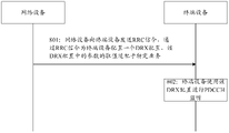
- the period during which the terminal device has not received an initial transmission indicated by the PDCCH scrambled by the C-RNTI after successfully receiving the random access response belongs to the DRX activation time.
- the terminal device determines the time to start drx-onDurationTimer according to whether the current DRX cycle is a short DRX cycle (short DRX cycle) or a long DRX cycle (long DRX cycle).
- the specific regulations are as follows:
- the conditions for the terminal device to start or restart drx-InactivityTimer are:
- the terminal device If the terminal device receives a PDCCH indicating initial downlink or uplink transmission, the terminal device starts or restarts drx-InactivityTimer.
- the conditions for the terminal device to start and stop drx-RetransmissionTimerDL are:
- the terminal device When the terminal device receives a PDCCH indicating downlink transmission, or when the terminal device receives a MAC PDU on the configured downlink authorization resource, the terminal device stops the drx-RetransmissionTimerDL corresponding to the HARQ process. After completing the transmission of the HARQ process feedback for this downlink transmission, the terminal device starts the drx-HARQ-RTT-TimerDL corresponding to the HARQ process.
- the terminal device If the drx-HARQ-RTT-TimerDL corresponding to a HARQ process of the terminal device times out, and the downlink data transmitted by this HARQ process is unsuccessfully decoded, the terminal device starts the drx-RetransmissionTimerDL corresponding to the HARQ process.
- the terminal device When the terminal device receives a PDCCH indicating uplink transmission, or when the terminal device sends a MAC PDU on the configured uplink authorization resource, the terminal device stops the drx-RetransmissionTimerUL corresponding to the HARQ process. The terminal device starts the drx-HARQ-RTT-TimerUL corresponding to the HARQ process after completing the first repeated transmission (repetition) of the PUSCH.
- the terminal device If the drx-HARQ-RTT-TimerUL corresponding to a certain HARQ process of the terminal device times out, the terminal device starts the drx-RetransmissionTimerUL corresponding to the HARQ process.
- drx-HARQ-RTT-TimerUL for uplink transmission
- drx-HARQ-RTT-TimerDL for downlink transmission
- the terminal device is in a dormant state during the running of the DRX HARQ RTT timer, and does not monitor the PDCCH.
- the terminal device starts to monitor the uplink retransmission scheduling or determines whether to start according to the feedback Monitor downlink retransmission scheduling.
- drx-HARQ-RTT-TimerUL and drx-HARQ-RTT-TimerDL are semi-statically configured by network equipment through RRC signaling.
- the DRX configuration configured by the network device for the terminal device is for the MAC entity, and only one DRX configuration is configured for one MAC entity, and there is only one DRX cycle in one DRX configuration (this is for the DRX long cycle and the DRX short cycle respectively, There is only one DRX long cycle and only one DRX short cycle).
- the unit of the DRX cycle is ms, and its value is a positive integer.
- the services faced by URLLC/XR are not services with integer multiple cycles.
- the arrival of services is also affected by jitter.
- FIG. 2 is a first schematic flow diagram of the DRX configuration method provided by the embodiment of the present application. As shown in FIG. 2, the DRX configuration method includes the following steps:
- Step 201 The network device sends first configuration information to the terminal device, and the terminal device receives the first configuration information sent by the network device, where the first configuration information is used to indicate one DRX configuration or multiple DRX configurations.
- Step 202 The terminal device monitors the PDCCH based on the one DRX configuration or the multiple DRX configurations.
- the network device may be a base station.
- the network device sends the first configuration information to the terminal device, the first configuration information is used to indicate one DRX configuration or multiple DRX configurations, and the one DRX configuration or multiple DRX configurations are used for the
- the terminal equipment monitors the PDCCH.
- the first configuration information is carried in RRC signaling.
- the one DRX configuration or multiple DRX configurations may be configured through RRC config in RRC signaling, such as DRX-config.
- the DRX configuration includes configuration information of at least one parameter, and the at least one parameter includes at least one of the following:
- a first parameter where the first parameter is used to indicate the DRX long cycle
- a second parameter, the second parameter is used to indicate the DRX short cycle
- a third parameter, the third parameter is used to indicate the offset or start time of the DRX long cycle
- a fourth parameter, the fourth parameter is used to indicate the offset or start time of the DRX short cycle.
- the at least one parameter also includes at least one of the following:
- a fifth parameter, the fifth parameter is used to indicate the duration of the DRX state timer
- a sixth parameter where the sixth parameter is used to indicate the duration of the DRX inactivity timer
- a seventh parameter, the seventh parameter is used to indicate the duration of the DRX retransmission timer
- the eighth parameter, the eighth parameter is used to indicate the duration of the HARQ RTT timer
- a ninth parameter, the ninth parameter is used to indicate the duration of the DRX short cycle timer.
- the third parameter and/or the fourth parameter are also used to indicate the time for delaying the start of at least one of the following timers or extending the running time:
- DRX state timer DRX inactivity timer
- DRX retransmission timer HARQ RTT timer
- DRX short cycle timer DRX short cycle timer
- the IE corresponding to the first parameter in the above solution may be "drx-LongCycle”
- the IE corresponding to the second parameter may be “drx-ShortCycle”
- the IE corresponding to the third parameter may be "drx-StartOffset”
- the IE corresponding to the second parameter may be "drx-StartOffset”.
- the IE corresponding to the four parameters can be "drx-StartOffset", the IE corresponding to the fifth parameter can be “drx-onDurationTimer”, the IE corresponding to the sixth parameter can be “drx-InactivityTimer”, and the IE corresponding to the seventh parameter can be " drx-RetransmissionTimer”, the IE corresponding to the eighth parameter may be "drx-HARQ-RTT-Timer”, and the IE corresponding to the ninth parameter may be "drx-ShortCycleTimer".
- drx-RetransmissionTimer has uplink and downlink points, such as drx-RetransmissionTimer UL and drx-RetransmissionTimer DL;
- drx-HARQ-RTT-Timer has uplink and downlink points, such as drx-HARQ-RTT-Timer UL and drx-HARQ -RTT-Timer DL.
- the names of the above IEs can be modified in different DRX configurations, for example: the IE corresponding to the first parameter can be "drx-LongCycle-ext ", the IE corresponding to the second parameter can be “drx-ShortCycle-ext", the IE corresponding to the third parameter can be “drx-StartOffset-ext", the IE corresponding to the fourth parameter can be “drx-StartOffset-ext”, The IE corresponding to the fifth parameter can be "drx-onDurationTimer-ext", the IE corresponding to the sixth parameter can be "drx-InactivityTimer-ext", the IE corresponding to the seventh parameter can be “drx-RetransmissionTimer-ext”, the eighth parameter can be The IE corresponding to the parameter may be “drx-HARQ-RTT-Timer-ext", and the IE corresponding to the ninth parameter may
- the first configuration information is used to indicate multiple DRX configurations.
- parameters configured in different DRX configurations among the multiple DRX configurations are different.
- the parameters configured in different DRX configurations among the multiple DRX configurations are different means that: in the multiple DRX configurations, at least some parameters configured in different DRX configurations have different values.
- the parameter types configured in different DRX configurations may be completely the same, or partly the same, or all different.
- the values of the parameter in the multiple DRX configurations are different.
- incremental configuration can be done, that is, configure a reference value, and then configure N-1 increments relative to the reference value, N is an integer greater than 1, one increment and one
- the reference value can determine a value of the parameter, N-1 increments and a reference value can determine N values of the parameter (the reference value can also be used as a value of the parameter).
- the absolute value can also be directly configured.
- the above configuration method is also applicable.
- the reference values corresponding to different parameters may be different, or the reference values corresponding to different parameters may also be the same.
- multiple DRX configurations correspond to multiple sets of parameters.
- a set of parameters for configuring absolute values may be the first set of parameters or a default set of parameters in multiple sets of parameters.
- each set of parameters in the multiple sets of parameters is used to indicate at least one of the following: DRX long cycle offset, DRX short cycle offset, DRX long cycle start time, DRX The start time of the short cycle, the duration of the DRX long cycle, and the duration of the DRX short cycle.
- at least one set of parameters in the plurality of sets of parameters is also used to indicate the delayed start time or extended running time of at least one of the following timers: DRX state timer, DRX inactivation timer, DRX restart timer Transmission timer, HARQ RTT timer, DRX short cycle timer.
- each DRX configuration in the multiple DRX configurations has a DRX configuration index; and/or, each DRX configuration in the multiple DRX configurations has a configuration type identifier, the The configuration type identifier is used to indicate that the DRX configuration is a common DRX configuration or a normal DRX configuration or a default DRX configuration or an extended DRX configuration.
- common DRX configuration is common DRX configuration
- regular DRX configuration is regular DRX configuration.
- Both common DRX and regular DRX configuration refer to existing DRX configurations, although this application refers to existing DRX configurations as common DRX configuration or conventional DRX configuration, but this application does not limit the name of the existing DRX configuration.
- the value of the parameter is an integer value and the value range of the parameter is fixed.
- the value of the parameter may be a non-integer value and the value range of the parameter is extended.
- the DRX configuration is set as the default or currently used or immediately used.
- the terminal device can use the DRX configuration for PDCCH monitor.
- the first DRX configuration in the plurality of DRX configurations is set as a default or currently used or immediately used, and the first DRX configuration may also be called a default DRX configuration.
- the network device configures three DRX configurations as DRX configuration 1, DRX configuration 2, and DRX configuration 3, wherein DRX configuration 2 is set as default or currently used or immediately used.
- values of at least some parameters in the first DRX configuration among the plurality of DRX configurations are set as default or currently used or immediately used.
- the network device configures three DRX configurations as DRX configuration 1, DRX configuration 2 and DRX configuration 3, wherein one or more parameters in DRX configuration 2 are set as default or currently used or used immediately.
- the multiple DRX configurations are configured by the network device based on the first information.
- the first information is obtained by the network device from the terminal device or core network or application layer.
- the first information includes at least one of the following: service data packet transmission period, service data packet arrival time, service data packet earliest arrival time, service data packet latest arrival time, service data packet Jitter, jitter range of service data packets, service arrival time point, service arrival time pattern.
- the multiple DRX configurations are configured for a MAC entity; or, the multiple DRX configurations are configured for a cell group; or, the multiple DRX configurations are configured for a medium
- the access control MAC entity is configured for all cells or carriers; or, the multiple DRX configurations are configured for all cells or carriers of a cell group.
- At least one DRX configuration among the multiple DRX configurations can be used as the DRX configuration for PDCCH monitoring, or multiple DRX configurations can be used together as the DRX configuration.
- DRX configuration for PDCCH monitoring the terminal device may determine which one or several DRX configurations need to be used for PDCCH monitoring in any of the following ways.
- the terminal device determines at least one DRX configuration from the plurality of DRX configurations as a DRX configuration for performing PDCCH monitoring.
- the terminal device determines at least one DRX configuration from the plurality of DRX configurations by itself as the DRX configuration for monitoring the PDCCH.
- the terminal device determines at least one DRX configuration from the multiple DRX configurations based on the first information.
- the terminal device reports second information to the network device, the network device receives the second information reported by the terminal device, and the second information is used to instruct the terminal device to determine DRX configuration for performing PDCCH monitoring.
- the second information is carried in a MAC CE or UCI or an uplink RRC message.
- the first information includes at least one of the following: service data packet transmission period, service data packet arrival time, service data packet earliest arrival time, service data packet latest arrival time, service data packet Jitter, jitter range of service data packets, service arrival time point, service arrival time pattern.
- the network device sends first indication information to the terminal device, where the first indication information is used to indicate a DRX configuration in the multiple DRX configurations, and the terminal device is based on the first indication sent by the network device
- the information determines at least one DRX configuration from the plurality of DRX configurations as a DRX configuration for performing PDCCH monitoring.
- the first indication information is used to indicate a DRX configuration index and/or a configuration type identifier
- the configuration type identifier is used to indicate that the DRX configuration is a common DRX configuration or a normal DRX configuration or a default DRX configuration or an extended DRX configuration.
- the first indication information is carried in at least one of the following signaling: RRC signaling, MAC CE, and DCI.
- the terminal device When the terminal device receives the first indication information sent by the network device, the terminal device uses the DRX configuration indicated by the first indication information as the DRX configuration for PDCCH monitoring;
- the terminal device uses the first DRX configuration in the multiple DRX configurations or the currently used DRX configuration as the PDCCH monitoring DRX configuration; wherein, the first DRX configuration is set as default or currently used or immediately used.
- the first indication information is used to indicate a DRX configuration index and/or a configuration type identifier
- the configuration type identifier is used to indicate that the DRX configuration is a common DRX configuration or a normal DRX configuration or a default DRX configuration or an extended DRX configuration.
- the first indication information is carried in at least one of the following signalings: RRC signaling, MAC CE, and DCI.
- the first configuration information is used to indicate a DRX configuration.
- the network device sends second indication information to the terminal device, and the terminal device receives the second indication information sent by the network device, where the second indication information is used to indicate that at least one of the one DRX configuration
- the value of the parameter is reactivated or updated.
- the second indication information is used to indicate at least one of the following: the name of the parameter to be reactivated or updated, and the update value of the parameter to be reactivated or updated.
- the update value of the parameter may be an absolute value of the parameter or an increment of the parameter relative to a reference value.
- the second indication information is carried in at least one of the following signaling: RRC signaling, MAC CE, and DCI.
- whether the value of the at least one parameter is reactivated or updated is determined by the network device based on the first information.
- the first information is obtained by the network device from the terminal device or core network or application layer.
- the first information includes at least one of the following: service data packet transmission period, service data packet arrival time, service data packet earliest arrival time, service data packet latest arrival time, service data packet Jitter, jitter range of service data packets, service arrival time point, service arrival time pattern.
- the terminal device after the terminal device receives the second indication information, it stops using the current value of the at least one parameter and/or starts using the at least one parameter immediately or at a first moment after the first duration.
- the updated value of a parameter is predefined or configured by a network device.
- the current value refers to the last value used by the terminal device before receiving the second indication information.
- the first moment may be: the first or Mth symbol after the end of the current DRX cycle.
- the first moment may be: the first or Mth symbol after N cycles are executed according to the current DRX cycle.
- the first moment may be: the first or Mth symbol after the current DRX activation (DRX ON) time ends.
- the first moment may be: the first or Mth symbol after the current DRX off (DRX OFF) time ends.
- the first moment may be: the first or Mth symbol after the receiving moment of the second indication information.
- M is an integer greater than 1, and M is a positive integer.
- symbol may also be replaced with “frame”, or “subframe”, or “half frame”, or “half time slot”, or “time slot”.
- the first configuration information is used to indicate a DRX configuration.
- the value of at least one parameter in the one DRX configuration is a non-integer value.
- the value of the duration of the DRX-related timer is a non-integer value.
- DRX-related timers include, for example: DRX state timer, DRX inactivity timer, DRX retransmission timer, HARQ RTT timer, and DRX short cycle timer.
- the value of the DRX cycle (that is, the DRX long cycle and the DRX short cycle) is a non-integer value.
- the value of the DRX cycle offset (that is, the DRX long cycle offset and the DRX short cycle offset) is a non-integer value.
- the IE corresponding to the DRX cycle offset may be "drx-StartOffset".
- the terminal device determines at least one of the following based on the DRX configuration: DRX activation time, DRX deactivation time, start time of DRX-related timers, and duration of DRX-related timers; wherein, the DRX The time domain position corresponding to the activation time is used for PDCCH monitoring.
- the method also includes at least one of the following:
- the terminal device performs edge alignment on the start time and/or end time of the DRX activation time
- the terminal device performs edge alignment on the start time and/or end time of the DRX off time
- the terminal device performs edge alignment on the duration and/or start time of the DRX-related timer
- the terminal device rounds the start time and/or end time of the DRX activation time, and determines the time domain position corresponding to the DRX activation time based on the rounded value; and/or,
- the terminal device rounds the start time and/or end time of the DRX off time, and determines the time domain position corresponding to the DRX off time based on the rounded value;
- the terminal device rounds the duration and/or start time of the DRX-related timer, and determines the time domain position corresponding to the running time of the timer based on the rounded value.
- the rounding is rounding up or rounding down.
- the edge alignment or rounding is for at least one of frame boundary, subframe boundary, time slot boundary, sub-slot (sub-slot) boundary, and symbol boundary.
- the start time of the DRX activation time, the end time of the DRX activation time, and the start time of the DRX off time may appear according to the value of the parameter.
- the end time of the DRX off time, the duration of the DRX-related timer, and the start time of the DRX-related timer are not aligned with the time domain units in the time domain.
- the time slot unit may be, for example, a subframe, a time slot, or a symbol. For this reason, these times or durations need to be edge-aligned to the time-domain unit, or in other words, these times or durations are rounded up or down to achieve alignment to the time-domain unit.
- the first configuration information is used to indicate to determine at least one DRX configuration, and the first configuration information is also used to determine multiple sets of parameters.
- At least one set of parameters among multiple sets of parameters may include only one parameter, or may include multiple parameters.
- each set of parameters in multiple sets of parameters may include only one parameter, or may include multiple parameters.
- the multiple sets of parameters are multiple sets of DRX cycle offsets, each set of DRX cycle offsets includes a DRX long cycle offset and/or a DRX cycle offset, or, each set of DRX cycle offsets includes An offset, where the offset is a DRX long cycle offset and/or a DRX cycle offset.
- the IE corresponding to the DRX cycle offset may be "drx-StartOffset".
- Network devices realize the configuration of multiple values for the same parameter through multiple sets of parameters.
- incremental configuration can be done, that is, configure a reference value, and then configure the N- 1 increment, N is an integer greater than 1, an increment and a reference value can determine a value of a parameter, N-1 increments and a reference value can determine N values of a parameter (the reference value is also can be used as a value for a parameter).
- the absolute value can also be directly configured.
- a specified set of parameters or the first set of parameters is set as default or currently used or immediately used.
- each set of parameters in the multiple sets of parameters is used to indicate at least one of the following:
- the offset of the DRX long cycle, the offset of the DRX short cycle, the start time of the DRX long cycle, and the start time of the DRX short cycle are the offset of the DRX long cycle, the offset of the DRX short cycle, the start time of the DRX long cycle, and the start time of the DRX short cycle.
- At least one set of parameters among the multiple sets of parameters is also used to indicate the time for delaying the start of at least one of the following timers or extending the running time:
- DRX state timer DRX inactivity timer
- DRX retransmission timer HARQ RTT timer
- DRX short cycle timer DRX short cycle timer
- values of the multiple sets of parameters are determined by the network device based on the first information.
- the first information is obtained by the network device from the terminal device or core network or application layer.
- the first information includes at least one of the following: service data packet transmission period, service data packet arrival time, service data packet earliest arrival time, service data packet latest arrival time, service data packet Jitter, jitter range of service data packets, service arrival time point, service arrival time pattern.
- the terminal device may use one DRX configuration in combination with one set of parameters among the multiple sets of parameters to perform PDCCH monitoring.
- the terminal device can determine which set of parameters needs to be used for PDCCH monitoring by any of the following methods.
- the terminal device determines a set of parameters for PDCCH monitoring from the multiple sets of parameters.
- the terminal device determines a set of parameters for PDCCH monitoring from the multiple sets of parameters by itself.
- the terminal device determines a set of parameters for performing PDCCH monitoring from the multiple sets of parameters based on the first information.
- the terminal device reports third information to the network device, the network device receives the third information sent by the terminal device, and the third information is used to instruct the terminal device to determine A set of parameters used for PDCCH monitoring.
- the third information is carried in a MAC CE or UCI or an uplink RRC message.
- the first information includes at least one of the following: service data packet transmission period, service data packet arrival time, service data packet earliest arrival time, service data packet latest arrival time, service data packet Jitter, jitter range of service data packets, service arrival time point, service arrival time pattern.
- the network device sends third indication information to the terminal device, where the third indication information is used to indicate a set of parameters in the multiple sets of parameters, and the terminal device is based on the third indication information sent by the network device
- a set of parameters for PDCCH monitoring is determined from the multiple sets of parameters.
- the third indication information is used to indicate an index of a set of parameters and/or a parameter type identifier
- the parameter type identifier is used to indicate whether a set of parameters is a common parameter or a regular parameter or a default parameter or an extended parameter.
- the third indication information is carried in at least one of the following signalings: RRC signaling, MAC CE, and DCI.
- the terminal device When the terminal device receives the third indication information sent by the network device, the terminal device uses a set of parameters indicated by the third indication information as a set of parameters for PDCCH monitoring;
- the terminal device When the terminal device does not receive the third indication information sent by the network device, the terminal device sets the specified set of parameters or the first set of parameters or the currently used set of parameters among the multiple sets of parameters, As a set of parameters for PDCCH monitoring; wherein, the designated set of parameters or the first set of parameters is a set of parameters set as default or currently used or immediately used among the multiple sets of parameters.
- the third indication information is used to indicate an index of a set of parameters and/or a parameter type identifier
- the parameter type identifier is used to indicate whether a set of parameters is a common parameter or a regular parameter or a default parameter or an extended parameter.
- the third indication information is carried in at least one of the following signaling: RRC signaling, MAC CE, DCI.
- the terminal device is a UE.
- FIG. 3 is a second schematic flow diagram of the DRX configuration method provided by the embodiment of the present application. As shown in FIG. 3 , the DRX configuration method includes the following steps:
- Step 301 The UE receives multiple DRX configurations configured by a network device.
- the multiple DRX configurations are configured for a MAC entity or configured for a cell group.
- the multiple DRX configurations are configured for all carriers or cells of the MAC entity, or configured for all carriers or cells of a cell group.
- each DRX configuration in the plurality of DRX configurations has a DRX configuration index and/or a configuration type identifier, and the configuration type identifier is used to indicate that the DRX configuration is a common DRX configuration or Regular DRX configuration or default DRX configuration or extended DRX configuration.
- one DRX configuration is set as default or currently used or immediately used.
- values of at least some parameters are set as default or currently used or immediately used.
- the DRX configuration includes configuration information of at least one parameter, and the at least one parameter includes at least one of the following: DRX long cycle, DRX short cycle, offset of DRX long cycle, DRX short cycle offset.
- the DRX configures at least one of the following IEs: drx-LongCycleStartOffset-Ext, drx-ShortCycle-ext, drx-SlotOffset-ext.
- the at least one parameter further includes at least one of the following: DRX state timer (drx-onDurationTimer), DRX inactivity timer (drx-InactivityTimer), DRX retransmission timer (drx-RetransmissionTimer), HARQ RTT timer (drx-HARQ-RTT-Timer), DRX short cycle timer (drx-ShortCycleTimer).
- the DRX configuration includes an offset (Offset) parameter.
- the Offset parameter can be an offset for the DRX long cycle (used to determine the start time of the DRX long cycle), or it can be for the DRX short cycle. Cycle offset (used to determine the start time of the DRX short cycle).
- the Offset parameter can also be an offset for other DRX parameters, for example, the Offset parameter is used to indicate at least one timer delay start time or extended running time: DRX state timer, DRX inactivation timing timer, DRX retransmission timer, HARQ RTT timer, DRX short cycle timer.
- incremental configuration can be done, that is, configure a reference value, and then configure N-1 increments relative to the reference value, where N is greater than 1
- An integer an increment and a reference value can determine a value of the parameter, and N-1 increments and a reference value can determine N values of the parameter (the reference value can also be used as a value of the parameter).
- the absolute value can also be directly configured.
- the multiple DRX configurations may be configured through RRC config in RRC signaling, such as DRX-config.
- the network device determines whether to configure multiple DRX configurations for the UE according to the first information.
- the first information comes from the UE (such as UE assistance information of the UE) or core network or application layer (such as an application server).
- the first information is for uplink, or downlink, or uplink and downlink.
- the first information includes at least one of the following: service data packet transmission period, service data packet arrival time, service data packet earliest arrival time, service data packet latest arrival time, service data packet jitter, service data packet Jitter range, service arrival time point, and service arrival time pattern.
- Step 302 the UE saves the multiple received DRX configurations, determines the DRX configuration to be used, and performs PDCCH monitoring according to the DRX configuration.
- UE monitors PDCCH according to DRX configuration, including: UE determines DRX activation time and/or DRX deactivation time according to DRX configuration, UE performs PDCCH monitoring during DRX activation time, and stops PDCCH monitoring during DRX deactivation time.
- the UE can determine the used DRX configuration according to any of the following methods:
- Way 1 UE determines which DRX parameter to use, or determines whether to use extended DRX configuration.
- the UE determines which DRX configuration to use according to the first information, or determines whether to use the extended DRX configuration.
- the UE reports second information to the network device, where the second information is used to indicate a DRX configuration that the UE determines to use, or indicate whether the UE uses an extended DRX configuration.
- the network device determines which DRX configuration is used by the UE according to the first information, or determines whether to use the extended DRX configuration.
- the UE determines which DRX configuration to use or whether to use the extended DRX configuration according to the indication information of the network device.
- the network device indicates which DRX configuration the UE uses through at least one of RRX signaling, DCI, and MAC CE, or indicates whether to use the extended DRX configuration.
- the indication information of the network device includes: an index of the DRX configuration and/or a configuration type identifier.
- the configuration type identifier may be, for example, ext, indicating that the network device instructs the UE to use the extended DRX configuration
- the configuration type identifier may be, for example, non -ext, indicates that the network device instructs the UE to use common DRX configuration or normal DRX configuration.
- Mode 3 In the case that the UE does not receive the indication information from the network device, the UE uses the existing DRX configuration, or does not use the extended DRX configuration.
- the UE uses the existing DRX configuration.
- the UE uses the extended DRX configuration, or uses the DRX configuration indicated by the indication information.
- one DRX configuration is configured as default or currently used or immediately used, and the UE uses the DRX configuration when it does not receive instruction information from the network device.
- cycle-related parameters and offset-related singular numbers can be configured independently.
- cycle-related parameters can be configured independently, and offset-related parameters can be configured uniformly.
- FIG. 4 is a third schematic flow diagram of the DRX configuration method provided in the embodiment of the present application. As shown in FIG. 4, the DRX configuration method includes the following steps:
- Step 401 the network device sends RRC signaling to the terminal device, and configures multiple DRX configurations for the terminal device through the RRC signaling.
- Step 402 the network device sends DCI to the terminal device, and indicates to the terminal device the DRX configuration selected from multiple DRX configurations through the DCI.
- Step 403 The terminal device uses the selected DRX configuration to monitor the PDCCH.
- the network device is configured with multiple DRX configurations, and the terminal device can flexibly use the DRX configuration in the multiple DRX configurations for PDCCH monitoring, ensuring low-latency transmission of services At the same time, unnecessary power consumption of the UE is avoided.
- Fig. 5 is a schematic flow diagram 4 of the DRX configuration method provided by the embodiment of the present application. As shown in Fig. 5, the DRX configuration method includes the following steps:
- Step 501 UE receives a DRX configuration configured by a network device.
- the one DRX configuration is configured for a MAC entity.
- the one DRX configuration is configured for all carriers or cells of the MAC entity, or configured for all carriers or cells of a cell group.
- the DRX configuration includes configuration information of at least one parameter, and the at least one parameter includes at least one of the following: DRX long cycle, DRX short cycle, offset of DRX long cycle, DRX short cycle offset.
- the DRX configures at least one of the following IEs: drx-LongCycleStartOffset-Ext, drx-ShortCycle-ext, drx-SlotOffset-ext.
- the at least one parameter further includes at least one of the following: DRX state timer (drx-onDurationTimer), DRX inactivity timer (drx-InactivityTimer), DRX retransmission timer (drx-RetransmissionTimer), HARQ RTT timer (drx-HARQ-RTT-Timer), DRX short cycle timer (drx-ShortCycleTimer).
- the DRX configuration can be configured through RRC config in RRC signaling, such as DRX-config.
- Step 502 the UE saves the received DRX configuration, and uses the DRX configuration to monitor the PDCCH.
- UE monitors PDCCH according to DRX configuration, including: UE determines DRX activation time and/or DRX deactivation time according to DRX configuration, UE performs PDCCH monitoring during DRX activation time, and stops PDCCH monitoring during DRX deactivation time.
- Step 503 The network device instructs the UE to update at least one parameter in the DRX configuration through indication information.
- the network device indicates to the UE to update the offset parameters in the DRX configuration through indication information, such as DRX long cycle offset (DRX long cycle offset), DRX short cycle offset (DRX short cycle offset).
- indication information such as DRX long cycle offset (DRX long cycle offset), DRX short cycle offset (DRX short cycle offset).
- DRX-related timers such as DRX state timer, DRX inactivation timer, DRX retransmission timer, HARQ RTT timer, DRX short-cycle cycle timing device etc.
- the indication information is carried in at least one of the following signalings: RRC signaling, DCI, and MAC CE.
- the indication information may include at least one of the following: the name of the parameter to be updated, and the modified value of the parameter to be updated (which may be an absolute value or an incremental value of the parameter).
- the updated parameter is only the offset of the DRX cycle, or the updated parameter is only the offset of the DRX cycle and only one DRX long cycle and DRX short cycle is configured, or the updated parameter is only When it is the offset of the DRX cycle and the offsets of the DRX long cycle and the DRX short cycle are updated at the same time, the indication information may only carry the modified value without carrying the name of the parameter.
- the indication information may include at least one of the following: the name of the parameter to be updated, and the modified value of the parameter to be updated (which may be an absolute value or an incremental value of the parameter).
- the parameter to be updated is the start time or running time of DRX-related timers.
- DRX-related timers such as DRX state timer, DRX inactivation timer, DRX retransmission timer, HARQ RTT timer, DRX short Periodic loop timer, etc.
- the network device determines whether to update parameters in the DRX configuration for the terminal device according to the first information.
- the first information comes from the UE (such as UE assistance information of the UE) or core network or application layer (such as an application server).
- the first information is for uplink, or downlink, or uplink and downlink.
- the first information includes at least one of the following: service data packet transmission period, service data packet arrival time, service data packet earliest arrival time, service data packet latest arrival time, service data packet jitter, service data packet Jitter range, service arrival time point, and service arrival time pattern.
- Step 504 After receiving the indication information, the UE uses the updated parameters to monitor the PDCCH.
- the UE stops using the current value of the parameter and/or uses the updated value of the parameter immediately or at the first moment of the first duration.
- the first duration and/or the first moment are predefined or configured by the network device.
- the first moment may be: the first or Mth symbol after the end of the current DRX cycle.
- the first moment may be: the first or Mth symbol after N cycles are executed according to the current DRX cycle.
- the first moment may be: the first or Mth symbol after the current DRX activation (DRX ON) time ends.
- the first moment may be: the first or Mth symbol after the current DRX off (DRX OFF) time ends;
- the first moment may be: the first or Mth symbol after the receiving moment of the indication information.
- M is an integer greater than 1, and M is a positive integer.
- symbol may also be replaced with “frame”, or “subframe”, or “half frame”, or “half time slot”, or “time slot”.
- FIG. 6 is a schematic flow diagram five of the DRX configuration method provided by the embodiment of the present application. As shown in FIG. 6, the DRX configuration method includes the following steps:
- Step 601 the network device sends RRC signaling to the terminal device, and configures a DRX configuration for the terminal device through the RRC signaling.
- Step 602 The terminal device uses the configured DRX configuration to monitor the PDCCH.
- Step 603 the network device sends DCI to the terminal device, and indicates to the terminal device the updated parameters in the DRX configuration through the DCI.
- the parameters in the DRX configuration are updated, which means that the DRX configuration is updated.
- Step 604 The terminal device uses the updated DRX configuration to monitor the PDCCH.
- the network device dynamically indicates the parameters to be updated, and realizes the flexible update of the DRX configuration. This way of updating the DRX configuration can effectively save signaling overhead.
- FIG. 7 is a schematic flow diagram VI of the DRX configuration method provided by the embodiment of the present application. As shown in FIG. 7, the DRX configuration method includes the following steps:
- Step 701 UE receives a DRX configuration configured by a network device, and values of parameters in the DRX configuration are adapted to specific services.
- the one DRX configuration is configured for a MAC entity.
- the one DRX configuration is configured for all carriers or cells of the MAC entity, or configured for all carriers or cells of a cell group.
- the DRX configuration includes configuration information of at least one parameter, and the at least one parameter includes at least one of the following: DRX long cycle, DRX short cycle, offset of DRX long cycle, DRX short cycle offset.
- the DRX configures at least one of the following IEs: drx-LongCycleStartOffset-Ext, drx-ShortCycle-ext, drx-SlotOffset-ext.
- the at least one parameter further includes at least one of the following: DRX state timer (drx-onDurationTimer), DRX inactivity timer (drx-InactivityTimer), DRX retransmission timer (drx-RetransmissionTimer), HARQ RTT timer (drx-HARQ-RTT-Timer), DRX short cycle timer (drx-ShortCycleTimer).
- the DRX configuration can be configured through RRC config in RRC signaling, such as DRX-config.
- the value of at least one parameter in the DRX configuration is a non-integer value.
- the value of the duration of the DRX-related timer is a non-integer value.
- DRX-related timers include, for example: DRX state timer, DRX inactivity timer, DRX retransmission timer, HARQ RTT timer, and DRX short cycle timer.
- the value of the DRX cycle (that is, the DRX long cycle and the DRX short cycle) is a non-integer value.
- the value of the DRX cycle offset (that is, the DRX long cycle offset and the DRX short cycle offset) is a non-integer value.
- the IE corresponding to the DRX cycle offset may be "drx-StartOffset".
- the value of the parameters in the DRX configuration is adapted to a specific service and meets the requirement of a non-integer multiple period of the specific service.
- the specific service may be, but not limited to, URLLC/XR type service.
- Step 702 the UE saves the received DRX configuration, and uses the DRX configuration to monitor the PDCCH.
- UE monitors PDCCH according to DRX configuration, including: UE determines DRX activation time and/or DRX deactivation time according to DRX configuration, UE performs PDCCH monitoring during DRX activation time, and stops PDCCH monitoring during DRX deactivation time.
- the start time of the DRX activation time, the end time of the DRX activation time, and the start time of the DRX off time may appear according to the value of the parameter.
- the end time of the DRX off time, the duration of the DRX-related timer, and the start time of the DRX-related timer are not aligned with the time domain units in the time domain.
- the time slot unit may be, for example, a subframe, a time slot, or a symbol. For this reason, these times or durations need to be edge-aligned to the time-domain unit, or in other words, these times or durations are rounded up or down to achieve alignment to the time-domain unit.
- FIG. 8 is a schematic flow diagram VII of the DRX configuration method provided by the embodiment of the present application. As shown in FIG. 8, the DRX configuration method includes the following steps:
- Step 801 The network device sends RRC signaling to the terminal device, and configures a DRX configuration for the terminal device through the RRC signaling, and values of parameters in the DRX configuration are adapted to specific services.
- Step 802 The terminal device uses the DRX configuration to monitor the PDCCH.
- a specific DRX configuration is configured for a specific service, and the value of the parameters in the DRX configuration is adapted to the specific service, which is simple to implement, and the terminal device can perform effective energy saving while receiving the specific service normally.
- FIG. 9 is an eighth schematic flowchart of a DRX configuration method provided in an embodiment of the present application. As shown in FIG. 9, the DRX configuration method includes the following steps:
- Step 901 UE receives a DRX configuration and multiple sets of offset parameters configured by a network device.
- the one DRX configuration is configured for a MAC entity.
- the one DRX configuration is configured for all carriers or cells of the MAC entity, or configured for all carriers or cells of a cell group.
- the DRX configuration includes configuration information of at least one parameter, and the at least one parameter includes at least one of the following: a DRX long cycle and a DRX short cycle.
- the at least one parameter further includes at least one of the following: DRX state timer (drx-onDurationTimer), DRX inactivity timer (drx-InactivityTimer), DRX retransmission timer (drx-RetransmissionTimer), HARQ RTT timer (drx-HARQ-RTT-Timer), DRX short cycle timer (drx-ShortCycleTimer).
- the DRX configuration can be configured through RRC config in RRC signaling, such as DRX-config.
- each set of offset parameters in multiple sets of offset parameters includes a DRX long cycle offset and/or a DRX cycle offset, or, each set of offset parameters includes an offset, and the offset The offset is the DRX long cycle offset and/or one DRX cycle offset.
- the network device realizes the configuration of multiple values for the offset parameter through multiple sets of offset parameters.
- incremental configuration can be done, that is, configure a reference value, and then configure N relative to the reference value.
- N is an integer greater than 1
- an increment and a reference value can determine a value of a parameter
- N-1 increments and a reference value can determine N values of a parameter (reference value It can also be used as a value of the parameter).
- the absolute value can also be directly configured.
- a specified set of offset parameters or the first set of offset parameters is set as a default or currently used or immediately used.
- each set of offset parameters in the multiple sets of offset parameters is used to indicate at least one of the following:
- the offset of the DRX long cycle, the offset of the DRX short cycle, the start time of the DRX long cycle, and the start time of the DRX short cycle are the offset of the DRX long cycle, the offset of the DRX short cycle, the start time of the DRX long cycle, and the start time of the DRX short cycle.
- each set of offset parameters in the multiple sets of offset parameters is also used to indicate at least one of the following timers to delay the start time or extend the running time:
- DRX state timer DRX inactivity timer
- DRX retransmission timer HARQ RTT timer
- DRX short cycle timer DRX short cycle timer
- the network device determines whether to configure multiple sets of offset parameters for the UE according to the first information.
- the first information comes from the UE (such as UE assistance information of the UE) or core network or application layer (such as an application server).
- the first information is for uplink, or downlink, or uplink and downlink.
- the first information includes at least one of the following: service data packet transmission period, service data packet arrival time, service data packet earliest arrival time, service data packet latest arrival time, service data packet jitter, service data packet Jitter range, service arrival time point, and service arrival time pattern.
- Step 902 The UE saves the received DRX configuration and multiple sets of offset parameters, determines the used offset parameter, and performs PDCCH monitoring according to the determined offset parameter and DRX configuration.
- the offset parameter and DRX configuration determined by the UE include: the offset parameter and DRX configuration determined by the UE determine the DRX activation time and/or the DRX deactivation time, and the UE performs PDCCH monitoring during the DRX activation time and stops PDCCH monitoring during the DRX deactivation time.
- the UE can determine the used offset parameter according to any of the following methods:
- Way 1 UE determines which set of offset parameters to use, or determines whether to use extended offset parameters by itself.
- the UE determines which set of offset parameters to use according to the first information, or determines whether to use extended offset parameters. Further, optionally, the UE reports third information to the network device, where the third information is used to indicate a set of offset parameters that the UE determines to use, or indicate whether the UE uses extended offset parameters.
- the network device determines which set of offset parameters the UE uses according to the first information, or determines whether to use extended offset parameters.
- the UE determines which set of offset parameters to use or whether to use extended offset parameters according to the indication information of the network device.
- the network device indicates which set of offset parameters the UE uses through at least one of RRX signaling, DCI, and MAC CE, or indicates whether to use an extended set of offset parameters.
- the indication information of the network device includes: an index of the offset parameter and/or a parameter type identifier.
- the parameter type identifier may be ext, which means that the network device instructs the UE to use the extended offset parameter, and the parameter type identifier may be non, for example. -ext, indicates that the network device instructs the UE to use common offset parameters or normal offset parameters.
- Mode 3 In the case that the UE does not receive the indication information from the network device, the UE uses the existing offset parameter, or does not use the extended offset parameter.
- the UE uses the existing offset parameter.
- the UE uses the extended offset parameter, or uses the offset parameter indicated by the indication information.
- one set of offset parameters is configured as default or currently used or immediately used, and the UE uses the offset parameter when the UE does not receive instruction information from the network device.
- FIG. 10 is a schematic flowchart of the ninth DRX configuration method provided by the embodiment of the present application. As shown in FIG. 10 , the DRX configuration method includes the following steps:
- Step 1001 The network device sends RRC signaling to the terminal device, and configures a DRX configuration and multiple sets of offset parameters for the terminal device through the RRC signaling.
- Step 1002 the network device sends DCI to the terminal device, and indicates to the terminal device the offset parameter selected from multiple sets of offset parameters through the DCI.
- Step 1003 The terminal device monitors the PDCCH by using the selected offset parameter and DRX configuration.
- the technical solution of the embodiment of the present application aiming at the new service requirements of URLLC/XR, provides a network device with a DRX configuration and multiple sets of offset parameters, and the terminal device can flexibly use the offset parameters in multiple sets of offset parameters and combine the DRX configuration to perform PDCCH Monitoring ensures low-latency transmission of services and avoids unnecessary power consumption of the UE. Since only the offset parameter is extended, the signaling overhead is also small, and the behavior of the terminal device is also relatively simple.
- the network device can be configured with DRX configuration for the existing service, or Configure the DRX configuration for the new service.
- the DRX configuration and/or the parameters in the DRX configuration correspond to different resources such as DRB/LCH, and the terminal device can determine the resources used by the service according to the DRB/LCH DRX configuration and/or parameters in the DRX configuration.
- sequence numbers of the above-mentioned processes do not mean the order of execution, and the order of execution of the processes should be determined by their functions and internal logic, and should not be used in this application.
- the implementation of the examples constitutes no limitation.
- the terms “downlink”, “uplink” and “sidelink” are used to indicate the transmission direction of signals or data, wherein “downlink” is used to indicate that the transmission direction of signals or data is sent from the station The first direction to the user equipment in the cell, “uplink” is used to indicate that the signal or data transmission direction is the second direction sent from the user equipment in the cell to the station, and “side line” is used to indicate that the signal or data transmission direction is A third direction sent from UE1 to UE2.
- “downlink signal” indicates that the transmission direction of the signal is the first direction.
- the term “and/or” is only an association relationship describing associated objects, indicating that there may be three relationships. Specifically, A and/or B may mean: A exists alone, A and B exist simultaneously, and B exists alone. In addition, the character "/" in this article generally indicates that the contextual objects are an "or” relationship.
- Fig. 11 is a schematic diagram of the first structural composition of the DRX configuration device provided by the embodiment of the present application, which is applied to a terminal device.
- the DRX configuration device includes:
- a receiving unit 1101 configured to receive first configuration information sent by a network device, where the first configuration information is used to indicate one DRX configuration or multiple DRX configurations;
- the monitoring unit 1102 is configured to monitor a Physical Downlink Control Channel (PDCCH) based on the one DRX configuration or the multiple DRX configurations.
- PDCCH Physical Downlink Control Channel
- the first configuration information is used to indicate multiple DRX configurations, and parameters configured in different DRX configurations in the multiple DRX configurations are different.
- each DRX configuration in the plurality of DRX configurations has a DRX configuration index
- Each DRX configuration in the plurality of DRX configurations has a configuration type identifier, and the configuration type identifier is used to indicate that the DRX configuration is a common DRX configuration or a normal DRX configuration or a default DRX configuration or an extended DRX configuration.
- the parameters configured in different DRX configurations among the multiple DRX configurations are different, which means:
- values of at least some parameters configured in different DRX configurations are different.
- the first DRX configuration in the plurality of DRX configurations is set as default or currently used or immediately used.
- values of at least some parameters in the first DRX configuration among the plurality of DRX configurations are set as default or currently used or immediately used.
- the multiple DRX configurations are configured by the network device based on the first information.
- the first information is obtained by the network device from the terminal device or a core network or an application layer.
- the apparatus further includes: a determining unit, configured to determine at least one DRX configuration from the plurality of DRX configurations as a DRX configuration for performing PDCCH monitoring.
- the determining unit is configured to determine at least one DRX configuration from the plurality of DRX configurations based on the first information.
- the apparatus further includes: a sending unit, configured to report second information to the network device, where the second information is used to indicate the DRX determined by the terminal device for performing PDCCH monitoring configuration.
- the second information is carried in a MAC CE or UCI or an uplink RRC message.
- the apparatus further includes: a determining unit, configured to determine at least one DRX configuration from the plurality of DRX configurations based on the first indication information sent by the network device, as a configuration for performing PDCCH monitoring. DRX configuration.
- the apparatus further includes: a determining unit configured to, when the terminal device receives the first indication information sent by the network device, configure the DRX indicated by the first indication information, As a DRX configuration for PDCCH monitoring; when the terminal device does not receive the first indication information sent by the network device, configure the first DRX in the multiple DRX configurations or configure the currently used DRX, As a DRX configuration for performing PDCCH monitoring; wherein, the first DRX configuration is set as default or currently used or immediately used.
- the first indication information is used to indicate a DRX configuration index and/or a configuration type identifier
- the configuration type identifier is used to indicate that the DRX configuration is a normal DRX configuration or a normal DRX configuration or a default DRX configuration. Configure or extend the DRX configuration.
- the first indication information is carried in at least one of the following signaling: RRC signaling, MAC CE, and DCI.
- the apparatus further includes: a determining unit configured to use part or all of the DRX configurations in the plurality of DRX configurations as DRX configurations for PDCCH monitoring.
- the first configuration information is used to indicate multiple DRX configurations
- the multiple DRX configurations are configured for a medium access control MAC entity; or, the multiple DRX configurations are configured for a cell group; or,
- the multiple DRX configurations are configured for all cells or carriers of a medium access control MAC entity; or,
- the multiple DRX configurations are configured for all cells or carriers of a cell group.
- the first configuration information is used to indicate a DRX configuration
- the receiving unit 1101 is further configured to receive second indication information sent by the network device, and the second indication information is used to Instructing to reactivate or update the value of at least one parameter in the one DRX configuration.
- the second indication information is used to indicate at least one of the following: the name of the parameter to be reactivated or updated, and the update value of the parameter to be reactivated or updated.
- the second indication information is carried in at least one of the following signaling: RRC signaling, MAC CE, and DCI.
- whether the value of the at least one parameter is reactivated or updated is determined by the network device based on the first information.
- the first information is obtained by the network device from the terminal device or a core network or an application layer.
- the terminal device after receiving the second indication information, stops using the current value of the at least one parameter and/or starts using the Update value of at least one parameter mentioned above.
- the first duration and/or the first moment are predefined or configured by a network device.
- the first configuration information is used to indicate a DRX configuration, and a value of at least one parameter in the DRX configuration is a non-integer value.
- the apparatus further includes: a determining unit, configured to determine at least one of the following based on the DRX configuration: DRX activation time, DRX deactivation time, start time of DRX related timer, DRX related The duration of the timer.
- a determining unit configured to determine at least one of the following based on the DRX configuration: DRX activation time, DRX deactivation time, start time of DRX related timer, DRX related The duration of the timer.
- the device further includes: a processing unit configured to perform at least one of the following:
- the rounding is rounding up or rounding down.
- the edge alignment or rounding is for at least one of a frame boundary, a subframe boundary, a slot boundary, a subslot boundary, and a symbol boundary.
- the first configuration information is used to indicate a DRX configuration, and the first configuration information is also used to determine multiple sets of parameters.
- a specified set of parameters or the first set of parameters is set as default or currently used or immediately used.
- each set of parameters in the multiple sets of parameters is used to indicate at least one of the following:
- the offset of the DRX long cycle, the offset of the DRX short cycle, the start time of the DRX long cycle, and the start time of the DRX short cycle are the offset of the DRX long cycle, the offset of the DRX short cycle, the start time of the DRX long cycle, and the start time of the DRX short cycle.
- At least one set of parameters among the multiple sets of parameters is also used to indicate the time for delaying the start of at least one of the following timers or extending the running time:
- DRX state timer DRX inactivity timer
- DRX retransmission timer HARQ RTT timer
- DRX short cycle timer DRX short cycle timer
- values of the multiple sets of parameters are determined by the network device based on the first information.
- the first information is obtained by the network device from the terminal device or a core network or an application layer.
- the apparatus further includes: a determining unit, configured to determine a set of parameters for performing PDCCH monitoring from the multiple sets of parameters.
- the determining unit is configured to determine a set of parameters for performing PDCCH monitoring from the multiple sets of parameters based on the first information.
- the apparatus further includes: a sending unit, configured to report third information to the network device, where the third information is used to indicate a PDCCH monitoring determined by the terminal device. set of parameters.
- the third information is carried in MAC CE or UCI or uplink RRC message.
- the apparatus further includes: a determining unit, configured to determine a set of parameters for performing PDCCH monitoring from the multiple sets of parameters based on the third indication information sent by the network device.
- the apparatus further includes: a determining unit, configured to, when the terminal device receives the third indication information sent by the network device, set a set of parameters indicated by the third indication information to , as a set of parameters for PDCCH monitoring; when the terminal device does not receive the third indication information sent by the network device, set a specified set of parameters or the first set of parameters or Taking the currently used set of parameters as a set of parameters for PDCCH monitoring; wherein, the specified set of parameters or the first set of parameters is set as default or currently used among the multiple sets of parameters or A set of parameters for immediate use.
- a determining unit configured to, when the terminal device receives the third indication information sent by the network device, set a set of parameters indicated by the third indication information to , as a set of parameters for PDCCH monitoring; when the terminal device does not receive the third indication information sent by the network device, set a specified set of parameters or the first set of parameters or Taking the currently used set of parameters as a set of parameters for PDCCH monitoring; wherein, the specified set
- the third indication information is used to indicate an index of a set of parameters and/or a parameter type identifier
- the parameter type identifier is used to indicate that a set of parameters is a common parameter or a regular parameter or a default parameter or extended parameters.
- the third indication information is carried in at least one of the following signalings: RRC signaling, MAC CE, and DCI.
- the first information includes at least one of the following: service data packet transmission period, service data packet arrival time, service data packet earliest arrival time, service data packet latest arrival time, service data packet Jitter, jitter range of service data packets, service arrival time point, service arrival time pattern.
- the DRX configuration includes configuration information of at least one parameter, and the at least one parameter includes at least one of the following:
- a first parameter where the first parameter is used to indicate the DRX long cycle
- a second parameter, the second parameter is used to indicate the DRX short cycle
- a third parameter, the third parameter is used to indicate the offset or start time of the DRX long cycle
- a fourth parameter, the fourth parameter is used to indicate the offset or start time of the DRX short cycle.
- the at least one parameter also includes at least one of the following:
- a fifth parameter, the fifth parameter is used to indicate the duration of the DRX state timer
- a sixth parameter where the sixth parameter is used to indicate the duration of the DRX inactivity timer
- a seventh parameter, the seventh parameter is used to indicate the duration of the DRX retransmission timer
- the eighth parameter, the eighth parameter is used to indicate the duration of the HARQ RTT timer
- a ninth parameter, the ninth parameter is used to indicate the duration of the DRX short cycle timer.
- the third parameter and/or the fourth parameter are also used to indicate the time for delaying the start of at least one of the following timers or extending the running time:
- DRX state timer DRX inactivity timer
- DRX retransmission timer HARQ RTT timer
- DRX short cycle timer DRX short cycle timer
- Fig. 12 is a schematic diagram of the second structural composition of the DRX configuration device provided by the embodiment of the present application, which is applied to network equipment.
- the DRX configuration device includes:
- a sending unit 1201 configured to send first configuration information to a terminal device, where the first configuration information is used to indicate one DRX configuration or multiple DRX configurations; the one DRX configuration or multiple DRX configurations are used for the terminal device Perform PDCCH monitoring.
- the first configuration information is used to indicate multiple DRX configurations, and parameters configured in different DRX configurations in the multiple DRX configurations are different.
- each DRX configuration in the plurality of DRX configurations has a DRX configuration index
- Each DRX configuration in the plurality of DRX configurations has a configuration type identifier, and the configuration type identifier is used to indicate that the DRX configuration is a common DRX configuration or a normal DRX configuration or a default DRX configuration or an extended DRX configuration.
- the parameters configured in different DRX configurations among the multiple DRX configurations are different, which means:
- values of at least some parameters configured in different DRX configurations are different.
- the first DRX configuration in the plurality of DRX configurations is set as default or currently used or immediately used.
- values of at least some parameters in the first DRX configuration among the plurality of DRX configurations are set as default or currently used or immediately used.
- the multiple DRX configurations are configured by the network device based on the first information.
- the first information is obtained by the network device from the terminal device or a core network or an application layer.
- the apparatus further includes: a receiving unit, configured to receive second information reported by the terminal device, where the second information is used to indicate the PDCCH monitoring determined by the terminal device. DRX configuration.
- the second information is carried in a MAC CE or UCI or an uplink RRC message.
- the sending unit 1201 is further configured to send first indication information to the terminal device, where the first indication information is used to indicate one DRX configuration in the multiple DRX configurations.
- the first indication information is used to indicate a DRX configuration index and/or a configuration type identifier
- the configuration type identifier is used to indicate that the DRX configuration is a normal DRX configuration or a normal DRX configuration or a default DRX configuration. Configure or extend the DRX configuration.
- the first indication information is carried in at least one of the following signaling: RRC signaling, MAC CE, and DCI.
- the first configuration information is used to indicate multiple DRX configurations
- the multiple DRX configurations are configured for one MAC entity; or,
- the multiple DRX configurations are configured for a cell group; or,
- the multiple DRX configurations are configured for all cells or carriers of a medium access control MAC entity; or,
- the multiple DRX configurations are configured for all cells or carriers of a cell group.
- the first configuration information is used to indicate a DRX configuration
- the sending unit 1201 is further configured to send second indication information to the terminal device, and the second indication information is used to indicate Reactivate or update the value of at least one parameter in the one DRX configuration.
- the second indication information is used to indicate at least one of the following: the name of the parameter to be reactivated or updated, and the update value of the parameter to be reactivated or updated.
- whether the value of the at least one parameter is reactivated or updated is determined by the network device based on the first information.
- the first information is obtained by the network device from the terminal device or a core network or an application layer.
- the first configuration information is used to indicate a DRX configuration, and a value of at least one parameter in the DRX configuration is a non-integer value.
- the first configuration information is used to indicate a DRX configuration, and the first configuration information is also used to determine multiple sets of parameters.
- among the multiple sets of parameters specify a set of parameters or consider the first set of parameters to be set as default or currently used or immediately used.
- each set of parameters in the multiple sets of parameters is used to indicate at least one of the following:
- the offset of the DRX long cycle, the offset of the DRX short cycle, the start time of the DRX long cycle, and the start time of the DRX short cycle are the offset of the DRX long cycle, the offset of the DRX short cycle, the start time of the DRX long cycle, and the start time of the DRX short cycle.
- each set of parameters in the multiple sets of parameters is also used to indicate at least one of the following timers to delay the start time or extend the running time:
- DRX state timer DRX inactivity timer
- DRX retransmission timer HARQ RTT timer
- DRX short cycle timer DRX short cycle timer
- values of the multiple sets of parameters are determined by the network device based on the first information.
- the first information is obtained by the network device from the terminal device or a core network or an application layer.
- the apparatus further includes: a receiving unit, configured to receive third information sent by the terminal device, where the third information is used to indicate the PDCCH monitoring determined by the terminal device. A set of parameters.
- the third information is carried in MAC CE or UCI or uplink RRC message.
- the sending unit 1201 is further configured to send third indication information to the terminal device, where the third indication information is used to indicate a set of parameters in the multiple sets of parameters.
- the third indication information is used to indicate an index of a set of parameters and/or a parameter type identifier
- the parameter type identifier is used to indicate that a set of parameters is a common parameter or a regular parameter or a default parameter or extended parameters.
- the third indication information is carried in at least one of the following signalings: RRC signaling, MAC CE, and DCI.
- the first information includes at least one of the following: service data packet transmission period, service data packet arrival time, service data packet earliest arrival time, service data packet latest arrival time, service data packet Jitter, jitter range of service data packets, service arrival time point, service arrival time pattern.
- the DRX configuration includes configuration information of at least one parameter, and the at least one parameter includes at least one of the following:
- a first parameter where the first parameter is used to indicate the DRX long cycle
- a second parameter, the second parameter is used to indicate the DRX short cycle
- a third parameter, the third parameter is used to indicate the offset or start time of the DRX long cycle
- a fourth parameter, the fourth parameter is used to indicate the offset or start time of the DRX short cycle.
- the at least one parameter also includes at least one of the following:
- a fifth parameter, the fifth parameter is used to indicate the duration of the DRX state timer
- a sixth parameter where the sixth parameter is used to indicate the duration of the DRX inactivity timer
- a seventh parameter, the seventh parameter is used to indicate the duration of the DRX retransmission timer
- the eighth parameter, the eighth parameter is used to indicate the duration of the HARQ RTT timer
- a ninth parameter, the ninth parameter is used to indicate the duration of the DRX short cycle timer.
- the third parameter and/or the fourth parameter are also used to indicate the time for delaying the start of at least one of the following timers or extending the running time:
- DRX state timer DRX inactivity timer
- DRX retransmission timer HARQ RTT timer
- DRX short cycle timer DRX short cycle timer
- Fig. 13 is a schematic structural diagram of a communication device 1300 provided by an embodiment of the present application.
- the communication device may be a terminal device or a network device.
- the communication device 1300 shown in FIG. 13 includes a processor 1310, and the processor 1310 can invoke and run a computer program from a memory, so as to implement the method in the embodiment of the present application.
- the communication device 1300 may further include a memory 1320 .
- the processor 1310 can invoke and run a computer program from the memory 1320, so as to implement the method in the embodiment of the present application.
- the memory 1320 may be an independent device independent of the processor 1310 , or may be integrated in the processor 1310 .
- the communication device 1300 may further include a transceiver 1330, and the processor 1310 may control the transceiver 1330 to communicate with other devices, specifically, to send information or data to other devices, or to receive other Information or data sent by the device.
- the processor 1310 may control the transceiver 1330 to communicate with other devices, specifically, to send information or data to other devices, or to receive other Information or data sent by the device.
- the transceiver 1330 may include a transmitter and a receiver.
- the transceiver 1330 may further include an antenna, and the number of antennas may be one or more.
- the communication device 1300 may specifically be the network device of the embodiment of the present application, and the communication device 1300 may implement the corresponding processes implemented by the network device in each method of the embodiment of the present application. For the sake of brevity, details are not repeated here. .
- the communication device 1300 may specifically be the mobile terminal/terminal device of the embodiment of the present application, and the communication device 1300 may implement the corresponding processes implemented by the mobile terminal/terminal device in each method of the embodiment of the present application, for the sake of brevity , which will not be repeated here.
- FIG. 14 is a schematic structural diagram of a chip according to an embodiment of the present application.
- the chip 1400 shown in FIG. 14 includes a processor 1410, and the processor 1410 can call and run a computer program from a memory, so as to implement the method in the embodiment of the present application.
- the chip 1400 may further include a memory 1420 .
- the processor 1410 can invoke and run a computer program from the memory 1420, so as to implement the method in the embodiment of the present application.
- the memory 1420 may be an independent device independent of the processor 1410 , or may be integrated in the processor 1410 .
- the chip 1400 may also include an input interface 1430 .
- the processor 1410 can control the input interface 1430 to communicate with other devices or chips, specifically, can obtain information or data sent by other devices or chips.
- the chip 1400 may also include an output interface 1440 .
- the processor 1410 can control the output interface 1440 to communicate with other devices or chips, specifically, can output information or data to other devices or chips.
- the chip can be applied to the network device in the embodiment of the present application, and the chip can implement the corresponding processes implemented by the network device in the methods of the embodiment of the present application.
- the chip can implement the corresponding processes implemented by the network device in the methods of the embodiment of the present application.
- the chip can be applied to the mobile terminal/terminal device in the embodiments of the present application, and the chip can implement the corresponding processes implemented by the mobile terminal/terminal device in the various methods of the embodiments of the present application.
- the chip can implement the corresponding processes implemented by the mobile terminal/terminal device in the various methods of the embodiments of the present application.
- the chip can implement the corresponding processes implemented by the mobile terminal/terminal device in the various methods of the embodiments of the present application.
- the chip can be applied to the mobile terminal/terminal device in the embodiments of the present application, and the chip can implement the corresponding processes implemented by the mobile terminal/terminal device in the various methods of the embodiments of the present application.
- the chip mentioned in the embodiment of the present application may also be called a system-on-chip, a system-on-chip, a system-on-a-chip, or a system-on-a-chip.
- FIG. 15 is a schematic block diagram of a communication system 1500 provided by an embodiment of the present application. As shown in FIG. 15 , the communication system 1500 includes a terminal device 1510 and a network device 1520 .
- the terminal device 1510 can be used to realize the corresponding functions realized by the terminal device in the above method
- the network device 1520 can be used to realize the corresponding functions realized by the network device in the above method.
- the processor in the embodiment of the present application may be an integrated circuit chip, which has a signal processing capability.
- each step of the above-mentioned method embodiment may be completed by an integrated logic circuit of hardware in a processor or an instruction in the form of software.
- the above-mentioned processor can be a general-purpose processor, a digital signal processor (Digital Signal Processor, DSP), an application-specific integrated circuit (Application Specific Integrated Circuit, ASIC), an off-the-shelf programmable gate array (Field Programmable Gate Array, FPGA) or other available Program logic devices, discrete gate or transistor logic devices, discrete hardware components.
- DSP Digital Signal Processor
- ASIC Application Specific Integrated Circuit
- FPGA Field Programmable Gate Array
- a general-purpose processor may be a microprocessor, or the processor may be any conventional processor, or the like.
- the steps of the method disclosed in the embodiments of the present application can be directly implemented by a hardware decoding processor, or implemented by a combination of hardware and software modules in the decoding processor.
- the software module can be located in a mature storage medium in the field such as random access memory, flash memory, read-only memory, programmable read-only memory or electrically erasable programmable memory, register.
- the storage medium is located in the memory, and the processor reads the information in the memory, and completes the steps of the above method in combination with its hardware.
- the memory in the embodiments of the present application may be a volatile memory or a nonvolatile memory, or may include both volatile and nonvolatile memories.
- the non-volatile memory can be read-only memory (Read-Only Memory, ROM), programmable read-only memory (Programmable ROM, PROM), erasable programmable read-only memory (Erasable PROM, EPROM), electronically programmable Erase Programmable Read-Only Memory (Electrically EPROM, EEPROM) or Flash.
- the volatile memory can be Random Access Memory (RAM), which acts as external cache memory.
- RAM Static Random Access Memory
- SRAM Static Random Access Memory
- DRAM Dynamic Random Access Memory
- Synchronous Dynamic Random Access Memory Synchronous Dynamic Random Access Memory
- SDRAM double data rate synchronous dynamic random access memory
- Double Data Rate SDRAM, DDR SDRAM enhanced synchronous dynamic random access memory
- Enhanced SDRAM, ESDRAM synchronous connection dynamic random access memory
- Synchlink DRAM, SLDRAM Direct Memory Bus Random Access Memory
- Direct Rambus RAM Direct Rambus RAM
- the memory in the embodiment of the present application may also be a static random access memory (static RAM, SRAM), a dynamic random access memory (dynamic RAM, DRAM), Synchronous dynamic random access memory (synchronous DRAM, SDRAM), double data rate synchronous dynamic random access memory (double data rate SDRAM, DDR SDRAM), enhanced synchronous dynamic random access memory (enhanced SDRAM, ESDRAM), synchronous connection Dynamic random access memory (synch link DRAM, SLDRAM) and direct memory bus random access memory (Direct Rambus RAM, DR RAM), etc. That is, the memory in the embodiments of the present application is intended to include, but not be limited to, these and any other suitable types of memory.
- the embodiment of the present application also provides a computer-readable storage medium for storing computer programs.
- the computer-readable storage medium can be applied to the network device in the embodiments of the present application, and the computer program enables the computer to execute the corresponding processes implemented by the network device in the methods of the embodiments of the present application.
- the computer program enables the computer to execute the corresponding processes implemented by the network device in the methods of the embodiments of the present application.
- the computer-readable storage medium can be applied to the mobile terminal/terminal device in the embodiments of the present application, and the computer program enables the computer to execute the corresponding processes implemented by the mobile terminal/terminal device in the various methods of the embodiments of the present application , for the sake of brevity, it is not repeated here.
- the embodiment of the present application also provides a computer program product, including computer program instructions.
- the computer program product may be applied to the network device in the embodiment of the present application, and the computer program instructions cause the computer to execute the corresponding process implemented by the network device in each method of the embodiment of the present application.
- the Let me repeat for the sake of brevity, the Let me repeat.
- the computer program product can be applied to the mobile terminal/terminal device in the embodiments of the present application, and the computer program instructions cause the computer to execute the corresponding processes implemented by the mobile terminal/terminal device in the methods of the embodiments of the present application, For the sake of brevity, details are not repeated here.
- the embodiment of the present application also provides a computer program.
- the computer program can be applied to the network device in the embodiment of the present application.
- the computer program executes the corresponding process implemented by the network device in each method of the embodiment of the present application.
- the computer program executes the corresponding process implemented by the network device in each method of the embodiment of the present application.
- the computer program can be applied to the mobile terminal/terminal device in the embodiment of the present application.
- the computer program executes each method in the embodiment of the present application to be implemented by the mobile terminal/terminal device
- the corresponding process will not be repeated here.
- the disclosed systems, devices and methods may be implemented in other ways.
- the device embodiments described above are only illustrative.
- the division of the units is only a logical function division. In actual implementation, there may be other division methods.
- multiple units or components can be combined or May be integrated into another system, or some features may be ignored, or not implemented.
- the mutual coupling or direct coupling or communication connection shown or discussed may be through some interfaces, and the indirect coupling or communication connection of devices or units may be in electrical, mechanical or other forms.
- the units described as separate components may or may not be physically separated, and the components shown as units may or may not be physical units, that is, they may be located in one place, or may be distributed to multiple network units. Part or all of the units can be selected according to actual needs to achieve the purpose of the solution of this embodiment.
- each functional unit in each embodiment of the present application may be integrated into one processing unit, each unit may exist separately physically, or two or more units may be integrated into one unit.
- the functions described above are realized in the form of software function units and sold or used as independent products, they can be stored in a computer-readable storage medium.
- the technical solution of the present application is essentially or the part that contributes to the prior art or the part of the technical solution can be embodied in the form of a software product, and the computer software product is stored in a storage medium, including Several instructions are used to make a computer device (which may be a personal computer, a server, or a network device, etc.) execute all or part of the steps of the methods described in the various embodiments of the present application.
- the aforementioned storage media include: U disk, mobile hard disk, read-only memory (Read-Only Memory,) ROM, random access memory (Random Access Memory, RAM), magnetic disk or optical disc, etc., which can store program codes. .
Abstract
本申请实施例提供一种DRX配置方法及装置、终端设备、网络设备,该方法包括:终端设备接收网络设备发送的第一配置信息,所述第一配置信息用于指示一个DRX配置或者多个DRX配置;所述终端设备基于所述一个DRX配置或者所述多个DRX配置,进行物理下行控制信道PDCCH监听。
Description
本申请实施例涉及移动通信技术领域,具体涉及一种非连续接收(Discontinuous Reception,DRX)配置方法及装置、终端设备、网络设备。
为了终端设备的节能,引入了非连续接收(Discontinuous Reception,DRX)机制。网络设备为终端设备配置DRX配置,终端设备使用该DRX配置进行物理下行控制信道(Physical Downlink Control Channel,PDCCH)监听,基于监听到的PDCCH中携带的调度信息去接收业务数据。
然而,目前的DRX配置并不能适配业务数据传输,这会造成终端设备需要接收业务数据的时候,终端设备处于非激活状态,导致无法进行PDCCH监听,从而导致无法接收业务数据;或者,会造成终端设备不需要接收业务数据的时候,终端设备处于激活状态,导致进行了无效的PDCCH监听,浪费了终端设备的功耗。
发明内容
本申请实施例提供一种DRX配置方法及装置、终端设备、网络设备、芯片、计算机可读存储介质、计算机程序产品、计算机程序。
本申请实施例提供的DRX配置方法,包括:
终端设备接收网络设备发送的第一配置信息,所述第一配置信息用于指示一个DRX配置或者多个DRX配置;
所述终端设备基于所述一个DRX配置或者所述多个DRX配置,进行PDCCH监听。
本申请实施例提供的DRX配置方法,包括:
网络设备向终端设备发送第一配置信息,所述第一配置信息用于指示一个DRX配置或者多个DRX配置;所述一个DRX配置或者多个DRX配置,用于所述终端设备进行PDCCH监听。
本申请实施例提供的DRX配置装置,应用于终端设备,所述装置包括:
接收单元,用于接收网络设备发送的第一配置信息,所述第一配置信息用于指示一个DRX配置或者多个DRX配置;
监听单元,用于基于所述一个DRX配置或者所述多个DRX配置,进行物理下行控制信道PDCCH监听。
本申请实施例提供的DRX配置装置,应用于网络设备,所述装置包括:
发送单元,用于向终端设备发送第一配置信息,所述第一配置信息用于指示一个DRX配置或者多个DRX配置;所述一个DRX配置或者多个DRX配置,用于所述终端设备进行PDCCH监听。
本申请实施例提供的终端设备,包括处理器和存储器。该存储器用于存储计算机程序,该处理器用于调用并运行该存储器中存储的计算机程序,执行上述的DRX配置方法。
本申请实施例提供的网络设备,包括处理器和存储器。该存储器用于存储计算机程序,该处理器用于调用并运行该存储器中存储的计算机程序,执行上述的DRX配置方法。
本申请实施例提供的芯片,用于实现上述的DRX配置方法。
具体地,该芯片包括:处理器,用于从存储器中调用并运行计算机程序,使得安装有该芯片的设备执行上述的DRX配置方法。
本申请实施例提供的计算机可读存储介质,用于存储计算机程序,该计算机程序使得计算机执行上述的DRX配置方法。
本申请实施例提供的计算机程序产品,包括计算机程序指令,该计算机程序指令使得计算机执行上述的DRX配置方法。
本申请实施例提供的计算机程序,当其在计算机上运行时,使得计算机执行上述的DRX配 置方法。
通过上述技术方案,网络设备为终端设备灵活配置一个DRX配置或者多个DRX配置,从而可以使得DRX配置最大程度地适配于业务数据传输,终端设备基于网络设备配置的一个DRX配置或者多个DRX配置进行PDCCH监听,一方面,可以保障终端设备正常接收业务数据,另一方面,也可以保障终端设备在正常接收业务数据的前提下,能够节省功耗。
此处所说明的附图用来提供对本申请的进一步理解,构成本申请的一部分,本申请的示意性实施例及其说明用于解释本申请,并不构成对本申请的不当限定。在附图中:
图1是本申请实施例的一个应用场景的示意图;
图2是本申请实施例提供的DRX配置方法的流程示意图一;
图3是本申请实施例提供的DRX配置方法的流程示意图二;
图4是本申请实施例提供的DRX配置方法的流程示意图三;
图5是本申请实施例提供的DRX配置方法的流程示意图四;
图6是本申请实施例提供的DRX配置方法的流程示意图五;
图7是本申请实施例提供的DRX配置方法的流程示意图六;
图8是本申请实施例提供的DRX配置方法的流程示意图七;
图9是本申请实施例提供的DRX配置方法的流程示意图八;
图10是本申请实施例提供的DRX配置方法的流程示意图九;
图11是本申请实施例提供的DRX配置装置的结构组成示意图一;
图12是本申请实施例提供的DRX配置装置的结构组成示意图二;
图13是本申请实施例提供的一种通信设备示意性结构图;
图14是本申请实施例的芯片的示意性结构图;
图15是本申请实施例提供的一种通信系统的示意性框图。
下面将结合本申请实施例中的附图,对本申请实施例中的技术方案进行描述,显然,所描述的实施例是本申请一部分实施例,而不是全部的实施例。基于本申请中的实施例,本领域普通技术人员在没有做出创造性劳动前提下所获得的所有其他实施例,都属于本申请保护的范围。
图1是本申请实施例的一个应用场景的示意图。
如图1所示,通信系统100可以包括终端设备110和网络设备120。网络设备120可以通过空口与终端设备110通信。终端设备110和网络设备120之间支持多业务传输。
应理解,本申请实施例仅以通信系统100进行示例性说明,但本申请实施例不限定于此。也就是说,本申请实施例的技术方案可以应用于各种通信系统,例如:长期演进(Long Term Evolution,LTE)系统、LTE时分双工(Time Division Duplex,TDD)、通用移动通信系统(Universal Mobile Telecommunication System,UMTS)、物联网(Internet of Things,IoT)系统、窄带物联网(Narrow Band Internet of Things,NB-IoT)系统、增强的机器类型通信(enhanced Machine-Type Communications,eMTC)系统、5G通信系统(也称为新无线(New Radio,NR)通信系统),或未来的通信系统等。
在图1所示的通信系统100中,网络设备120可以是与终端设备110通信的接入网设备。接入网设备可以为特定的地理区域提供通信覆盖,并且可以与位于该覆盖区域内的终端设备110(例如UE)进行通信。
网络设备120可以是长期演进(Long Term Evolution,LTE)系统中的演进型基站(Evolutional Node B,eNB或eNodeB),或者是下一代无线接入网(Next Generation Radio Access Network,NG RAN)设备,或者是NR系统中的基站(gNB),或者是云无线接入网络(Cloud Radio Access Network,CRAN)中的无线控制器,或者该网络设备120可以为中继站、接入点、车载设备、可穿戴设备、集线器、交换机、网桥、路由器,或者未来演进的公共陆地移动网络(Public Land Mobile Network,PLMN)中的网络设备等。
终端设备110可以是任意终端设备,其包括但不限于与网络设备120或其它终端设备采用有线或者无线连接的终端设备。
例如,所述终端设备110可以指接入终端、用户设备(User Equipment,UE)、用户单元、用户站、移动站、移动台、远方站、远程终端、移动设备、用户终端、终端、无线通信设备、用户代理或用户装置。接入终端可以是蜂窝电话、无绳电话、会话启动协议(Session Initiation Protocol,SIP)电话、IoT设备、卫星手持终端、无线本地环路(Wireless Local Loop,WLL)站、个人数字处理(Personal Digital Assistant,PDA)、具有无线通信功能的手持设备、计算设备或连接到无线调制解调器的其它处理设备、车载设备、可穿戴设备、5G网络中的终端设备或者未来演进网络中的终端设备等。
终端设备110可以用于设备到设备(Device to Device,D2D)的通信。
无线通信系统100还可以包括与基站进行通信的核心网设备130,该核心网设备130可以是5G核心网(5G Core,5GC)设备,例如,接入与移动性管理功能(Access and Mobility Management Function,AMF),又例如,认证服务器功能(Authentication Server Function,AUSF),又例如,用户面功能(User Plane Function,UPF),又例如,会话管理功能(Session Management Function,SMF)。可选地,核心网络设备130也可以是LTE网络的分组核心演进(Evolved Packet Core,EPC)设备,例如,会话管理功能+核心网络的数据网关(Session Management Function+Core Packet Gateway,SMF+PGW-C)设备。应理解,SMF+PGW-C可以同时实现SMF和PGW-C所能实现的功能。在网络演进过程中,上述核心网设备也有可能叫其它名字,或者通过对核心网的功能进行划分形成新的网络实体,对此本申请实施例不做限制。
通信系统100中的各个功能单元之间还可以通过下一代网络(next generation,NG)接口建立连接实现通信。
例如,终端设备通过NR接口与接入网设备建立空口连接,用于传输用户面数据和控制面信令;终端设备可以通过NG接口1(简称N1)与AMF建立控制面信令连接;接入网设备例如下一代无线接入基站(gNB),可以通过NG接口3(简称N3)与UPF建立用户面数据连接;接入网设备可以通过NG接口2(简称N2)与AMF建立控制面信令连接;UPF可以通过NG接口4(简称N4)与SMF建立控制面信令连接;UPF可以通过NG接口6(简称N6)与数据网络交互用户面数据;AMF可以通过NG接口11(简称N11)与SMF建立控制面信令连接;SMF可以通过NG接口7(简称N7)与PCF建立控制面信令连接。
图1示例性地示出了一个基站、一个核心网设备和两个终端设备,可选地,该无线通信系统100可以包括多个基站设备并且每个基站的覆盖范围内可以包括其它数量的终端设备,本申请实施例对此不做限定。
需要说明的是,图1只是以示例的形式示意本申请所适用的系统,当然,本申请实施例所示的方法还可以适用于其它系统。此外,本文中术语“系统”和“网络”在本文中常被可互换使用。本文中术语“和/或”,仅仅是一种描述关联对象的关联关系,表示可以存在三种关系,例如,A和/或B,可以表示:单独存在A,同时存在A和B,单独存在B这三种情况。另外,本文中字符“/”,一般表示前后关联对象是一种“或”的关系。还应理解,在本申请的实施例中提到的“指示”可以是直接指示,也可以是间接指示,还可以是表示具有关联关系。举例说明,A指示B,可以表示A直接指示B,例如B可以通过A获取;也可以表示A间接指示B,例如A指示C,B可以通过C获取;还可以表示A和B之间具有关联关系。还应理解,在本申请的实施例中提到的“对应”可表示两者之间具有直接对应或间接对应的关系,也可以表示两者之间具有关联关系,也可以是指示与被指示、配置与被配置等关系。还应理解,在本申请的实施例中提到的“预定义”或“预定义规则”可以通过在设备(例如,包括终端设备和网络设备)中预先保存相应的代码、表格或其他可用于指示相关信息的方式来实现,本申请对于其具体的实现方式不做限定。比如预定义可以是指协议中定义的。还应理解,本申请实施例中,所述"协议"可以指通信领域的标准协议,例如可以包括LTE协议、NR协议以及应用于未来的通信系统中的相关协议,本申请对此不做限定。
为便于理解本申请实施例的技术方案,以下对本申请实施例的相关技术进行说明,以下相关技术作为可选方案与本申请实施例的技术方案可以进行任意结合,其均属于本申请实施例的保护范围。
URLLC/XR
在未来,第三代合作伙伴计划(3
rd Generation Partnership Project,3GPP)系统对垂直行业的支持会越来越广泛和深入。比如,低时延高可靠通信(Ultra-Reliable Low-Latency Communications,URLLC)需求支持工业自动化(Factory automation)、传输自动化(Transport Industry)、智能电力(Electrical Power Distribution)等业务在5G系统的传输。未来无线(X Radio,XR)需求支持增强现实(Augmented Reality,AR)、虚拟现实(Virtual Reality,VR)、云游戏(Cloud gaming)等业务传输。这些业务普遍存在可靠性和时延的要求,因为为终端设备调度资源时其要满足数据传输的服 务质量(Quality of Service,QoS)需求。从终端设备来说,还需要满足终端设备功耗的问题,避免不必要的功耗。同时,考虑到大量的支持这种类型的业务的终端设备的接入问题,在资源分配时还需要保证网络容量的需求。
典型的,对URLLC/XR来说,需要支持最小0.5ms时延,99,999%可靠性需求的业务。业务的可以是伪周期的,即业务到达时间存在抖动(jitter),或者说,业务不会在一个确定的时间点,而是会在一个时间范围内的任一个时刻到达。同时,业务周期可以是非整数周期,如16.67ms。此外,同一个业务的不同业务流到达的时间差别可能很大。
5G NR中的DRX机制
在5G NR中,网络设备可以为终端设备配置DRX配置,使终端设备非连续地监听PDCCH,以达到终端设备省电的目的。每个媒体接入控制(Media Access Control,MAC)实体有一个DRX配置,作为示例,DRX配置中配置的参数有:
-DRX状态定时器(drx-onDurationTimer):用于确定DRX周期开始后的一段时间;
-DRX时隙偏移量(drx-SlotOffset):用于确定启动DRX状态定时器之前的时延;
-DRX非激活定时器(drx-InactivityTimer):用于确定PDCCH时机(PDCCH occasion)之后的一段时间,其中,该PDCCH时机中被检测到PDCCH且该PDCCH指示了一个新的上行或下行传输;
-下行DRX重传定时器(drx-RetransmissionTimerDL):用于确定接收到下行重传之前的最长时间;
-上行DRX重传定时器(drx-RetransmissionTimerUL):用于确定在接收到上行重传的授权之前的最长时间;
-DRX长周期开始偏移量(drx-LongCycleStartOffset):用于确定DRX长周期和DRX开始时间偏移量(drx-StartOffset),其中,drx-StartOffset用于确定DRX长周期和DRX短周期的开始时间(例如开始时间对应的子帧);
-DRX短周期(drx-ShortCycle):为可选配置,用于确定DRX短周期;
-DRX短周期循环定时器(drx-ShortCycleTimer):为可选配置,用于确定DRX短周期的持续时间,其取值指代的是DRX短周期的倍数;
-下行DRX HARQ RTT定时器(drx-HARQ-RTT-TimerDL):MAC实体期望的用于HARQ重传的下行分配之前的最小持续时间;
-上行DRX HARQ RTT定时器(drx-HARQ-RTT-TimerUL):MAC实体期望的用于HARQ重传的上行授权之前的最小持续时间。
如果终端设备配置了DRX配置,则终端设备需要在DRX激活时间(即DRX ON)监听PDCCH。DRX激活时间包括如下几种情况:
1)drx-onDurationTimer、drx-InactivityTimer、drx-RetransmissionTimerDL、drx-RetransmissionTimerUL以及ra-ContentionResolutionTimer这5个定时器中的任何一个定时器的运行期间属于DRX激活时间。
2)终端设备在物理上行控制信道(Physical Uplink Control Channel,PUCCH)上发送了调度请求(SR)后,该SR处于悬挂(pending)状态期间属于DRX激活时间。
3)在基于竞争的随机接入过程中,终端设备在成功接收到随机接入响应后还没有接收到C-RNTI加扰的PDCCH指示的一次初始传输的期间属于DRX激活时间。
终端设备根据当前使用DRX周期是DRX短周期(short DRX cycle)还是DRX长周期(long DRX cycle),来决定启动drx-onDurationTimer的时间,具体规定如下:
1>如果使用的是DRX短周期,那么,drx-onDurationTimer的启动时间的子帧编号满足:[(SFN×10)+subframe number]modulo(drx-ShortCycle)=(drx-StartOffset)modulo(drx-ShortCycle);
1>如果使用的是DRX长周期,那么,drx-onDurationTimer的启动时间的子帧编号满足:[(SFN×10)+subframe number]modulo(drx-LongCycle)=drx-StartOffset;
2>在当前子帧开始的drx-SlotOffset个时隙之后的时刻启动drx-onDurationTimer。
终端设备启动或重启drx-InactivityTimer的条件为:
如果终端设备接收到一个指示下行或者上行的初始传输的PDCCH,则终端设备启动或者重启drx-InactivityTimer。
终端设备启动和停止drx-RetransmissionTimerDL的条件为:
当终端设备接收到一个指示下行传输的PDCCH,或者当终端设备在配置的下行授权资源上接收到一个MAC PDU,则终端设备停止该HARQ进程对应的drx-RetransmissionTimerDL。终端设备在 完成针对这次下行传输的HARQ进程反馈的传输之后启动该HARQ进程对应的drx-HARQ-RTT-TimerDL。
如果终端设备的某个HARQ进程对应的drx-HARQ-RTT-TimerDL超时,并且使用这个HARQ进程传输的下行数据解码不成功,则终端设备启动这个HARQ进程对应的drx-RetransmissionTimerDL。
终端设备启动和停止drx-RetransmissionTimerUL的条件为:
当终端设备接收到一个指示上行传输的PDCCH,或者当终端设备在配置的上行授权资源上发送一个MAC PDU,则终端设备停止该HARQ进程对应的drx-RetransmissionTimerUL。终端设备在完成这次PUSCH的第一次重复传输(repetition)之后启动该HARQ进程对应的drx-HARQ-RTT-TimerUL。
如果终端设备的某个HARQ进程对应的drx-HARQ-RTT-TimerUL超时,则终端设备启动这个HARQ进程对应的drx-RetransmissionTimerUL。
从以上DRX机制可以看出,终端设备在完成上行传输或者完成针对下行传输的HARQ进程反馈之后都会先启动一个DRX HARQ RTT定时器(对于上行传输是drx-HARQ-RTT-TimerUL,对于下行传输是drx-HARQ-RTT-TimerDL),终端设备在该DRX HARQ RTT定时器运行期间处于休眠状态,不监听PDCCH,等到该定时器超时后终端设备才开始监听上行重传调度或者根据反馈情况确定是否开始监听下行重传调度。其中,drx-HARQ-RTT-TimerUL和drx-HARQ-RTT-TimerDL由网络设备通过RRC信令半静态配置。
网络设备为终端设备配置的DRX配置,是针对MAC实体的,一个MAC实体仅配置一个DRX配置,一个DRX配置中仅有一个DRX周期(这里是针对DRX长周期和DRX短周期分别来说的,仅有一个DRX长周期,仅有一个DRX短周期)。DRX周期以ms为单位,其取值为正整值。而URLLC/XR面对的业务并不是整数倍周期的业务,另外,业务到达还存在抖动的影响。这会造成终端设备需要监听调度该类型的业务的PDCCH的时候,终端设备处于非激活状态,导致PDCCH没能监听,造成业务的调度和传输出现问题。或者,终端设备不需要监听PDCCH的时候,却错误的维持在激活状态,进行了不必要的PDCCH监听,导致了不必要的功耗。
为此,提出了本申请实施例的以下技术方案。需要说明的是,本申请实施例的技术方案可以但不局限于应用于上述描述的URLLC/XR类型的业务。任意类型的业务都适用于本申请实施例的技术方案。
为便于理解本申请实施例的技术方案,以下通过具体实施例详述本申请的技术方案。以上相关技术作为可选方案与本申请实施例的技术方案可以进行任意结合,其均属于本申请实施例的保护范围。本申请实施例包括以下内容中的至少部分内容。
图2是本申请实施例提供的DRX配置方法的流程示意图一,如图2所示,所述DRX配置方法包括以下步骤:
步骤201:网络设备向终端设备发送第一配置信息,终端设备接收网络设备发送的第一配置信息,所述第一配置信息用于指示一个DRX配置或者多个DRX配置。
步骤202:所述终端设备基于所述一个DRX配置或者所述多个DRX配置,进行PDCCH监听。
在一些可选实施方式中,所述网络设备可以是基站。
本申请实施例中,网络设备向终端设备发送第一配置信息,所述第一配置信息用于指示一个DRX配置或者多个DRX配置,所述一个DRX配置或者多个DRX配置,用于所述终端设备进行PDCCH监听。
在一些可选实施方式中,所述第一配置信息携带在RRC信令中。作为示例,所述一个DRX配置或者多个DRX配置可以通过RRC信令中的RRC config,如DRX-config进行配置。
在一些可选实施方式中,所述DRX配置包括至少一个参数的配置信息,所述至少一个参数包括以下至少之一:
第一参数,所述第一参数用于指示DRX长周期;
第二参数,所述第二参数用于指示DRX短周期;
第三参数,所述第三参数用于指示DRX长周期的偏移量或开始时间;
第四参数,所述第四参数用于指示DRX短周期的偏移量或开始时间。
进一步,在一些可选实施方式中,所述至少一个参数还包括以下至少之一:
第五参数,所述第五参数用于指示DRX状态定时器的时长;
第六参数,所述第六参数用于指示DRX非激活定时器的时长;
第七参数,所述第七参数用于指示DRX重传定时器的时长;
第八参数,所述第八参数用于指示HARQ RTT定时器的时长;
第九参数,所述第九参数用于指示DRX短周期循环定时器的时长。
在一些可选实施方式中,所述第三参数和/或所述第四参数还用于指示以下至少一种定时器延迟开启的时间或者延长运行的时间:
DRX状态定时器、DRX非激活定时器、DRX重传定时器、HARQ RTT定时器、DRX短周期循环定时器。
作为示例,上述方案中的第一参数对应的IE可以是“drx-LongCycle”,第二参数对应的IE可以是“drx-ShortCycle”,第三参数对应的IE可以是“drx-StartOffset”,第四参数对应的IE可以是“drx-StartOffset”,第五参数对应的IE可以是“drx-onDurationTimer”,第六参数对应的IE可以是“drx-InactivityTimer”,第七参数对应的IE可以是“drx-RetransmissionTimer”,第八参数对应的IE可以是“drx-HARQ-RTT-Timer”,第九参数对应的IE可以是“drx-ShortCycleTimer”。
这里,drx-RetransmissionTimer有上行和下行之分,例如drx-RetransmissionTimer UL和drx-RetransmissionTimer DL;drx-HARQ-RTT-Timer有上行和下行之分,例如drx-HARQ-RTT-Timer UL和drx-HARQ-RTT-Timer DL。
对于多个DRX配置的情况,为了区分不同DRX配置中的同一类参数,可以在不同的DRX配置中针对上述IE的名称进行修改,例如:第一参数对应的IE可以是“drx-LongCycle-ext”,第二参数对应的IE可以是“drx-ShortCycle-ext”,第三参数对应的IE可以是“drx-StartOffset-ext”,第四参数对应的IE可以是“drx-StartOffset-ext”,第五参数对应的IE可以是“drx-onDurationTimer-ext”,第六参数对应的IE可以是“drx-InactivityTimer-ext”,第七参数对应的IE可以是“drx-RetransmissionTimer-ext”,第八参数对应的IE可以是“drx-HARQ-RTT-Timer-ext”,第九参数对应的IE可以是“drx-ShortCycleTimer-ext”。
以下结合网络设备配置不同数目的DRX配置对本申请实施例的技术方案分情况进行说明。
方案一
本申请实施例中,所述第一配置信息用于指示多个DRX配置。这里,所述多个DRX配置中的不同DRX配置中配置的参数是不同的。
这里,所述多个DRX配置中的不同DRX配置中配置的参数是不同的,是指:在所述多个DRX配置中,不同DRX配置中配置的至少部分参数的取值不同。
需要说明的是,不同的DRX配置中配置的参数类型可以完全相同,或者部分相同,或者全部不同。对于一个参数在多个DRX配置中都配置的情况下,该参数在多个DRX配置中的取值是不同的。针对同一参数的多个取值的配置,可以做增量配置,即配置一个参考值,再配置相对于该参考值的N-1个增量,N为大于1的整数,一个增量和一个参考值可以确定参数的一个取值,N-1个增量和一个参考值可以确定出参数的N个取值(参考值也可以作为参数的一个取值)。或者,针对同一参数的多个取值的配置,也可以直接配置绝对值。
对于多个参数的取值的情况,同样适用于上述配置方式。对于基于参考值配置参数的取值的方式,不同参数对应的参考值可以不同,或者,不同参数对应的参考值也可以相同。例如:多个DRX配置对应多套参数,针对多套参数的配置,可以直接配置每套参数的绝对值,或者,可以针对其中一套参数配置其绝对值,而其他套参数配置相对于该套参数的增量,这里,可选地,配置绝对值的一套参数可以是多套参数中的第一套参数或者默认的一套参数。
在一些可选实施方式中,所述多套参数中的每套参数用于指示以下至少之一:DRX长周期的偏移量、DRX短周期的偏移量、DRX长周期的开始时间、DRX短周期的开始时间、DRX长周期的时长,DRX短周期的时长。进一步,可选地,所述多套参数中的至少一套参数还用于指示以下至少一种定时器延迟开启的时间或者延长运行的时间:DRX状态定时器、DRX非激活定时器、DRX重传定时器、HARQ RTT定时器、DRX短周期循环定时器。
在一些可选实施方式中,所述多个DRX配置中的每个DRX配置具有一个DRX配置索引;和/或,所述多个DRX配置中的每个DRX配置具有一个配置类型标识,所述配置类型标识用于指示该DRX配置是普通DRX配置或者常规DRX配置或者默认DRX配置或者扩展DRX配置。
这里,普通DRX配置即为common DRX configuration,常规DRX配置即为regular DRX configuration,普通DRX和常规DRX配置都是指代目前已有的DRX配置,虽然本申请将已有的DRX配置称为普通DRX配置或者常规DRX配置,但本申请对已有的DRX配置的名称不做限定。需要说明的是,在已有的DRX配置中,参数的取值为整数数值且参数的取值范围是固定的。相对于已有的DRX配置来说,在扩展DRX配置中,参数的取值可以是非整数数值且参数的取值范围被扩展了。 对于默认DRX配置来说,该DRX配置被设置为默认的或者当前使用的或者即刻使用的,在终端设备没有接收到网络设备指示的DRX配置的情况下,终端设备可以使用该DRX配置用于PDCCH监听。
在一些可选实施方式中,所述多个DRX配置中的第一DRX配置被设置为默认的或者当前使用的或者即刻使用的,第一DRX配置也可以称为默认DRX配置。
作为示例,网络设备配置3个DRX配置分别为DRX配置1、DRX配置2和DRX配置3,其中,DRX配置2被设置为默认的或者当前使用的或者即刻使用的。
在一些可选实施方式中,所述多个DRX配置中的第一DRX配置中的至少部分参数的取值被设置为默认的或者当前使用的或者即刻使用的。
作为示例,网络设备配置3个DRX配置分别为DRX配置1、DRX配置2和DRX配置3,其中,DRX配置2中的一个或多个参数被设置为默认的或者当前使用的或者即刻使用的。
在一些可选实施方式中,所述多个DRX配置由所述网络设备基于第一信息进行配置。这里,所述第一信息由所述网络设备从所述终端设备或者核心网或者应用层获得。
在一些可选实施方式中,所述第一信息包括以下至少之一:业务数据包传输周期、业务数据包达到时间、业务数据包最早到达时间、业务数据包最晚到达时间、业务数据包的抖动、业务数据包的抖动范围、业务到达时间点、业务到达时间图样。
在一些可选实施方式中,所述多个DRX配置为针对一个MAC实体配置的;或者,所述多个DRX配置为针对一个小区组配置的;或者,所述多个DRX配置为针对一个媒体接入控制MAC实体的所有小区或载波配置的;或者,所述多个DRX配置为针对一个小区组的所有小区或载波配置的。
本申请实施例中,终端设备获得网络设备配置的多个DRX配置后,可以将多个DRX配置中的至少一个DRX配置作为用于进行PDCCH监听的DRX配置,也可以将多个DRX配置共同作为用于进行PDCCH监听的DRX配置。对于终端设备使用多个DRX配置中的至少一个DRX配置用于进行PDCCH监听的情况,终端设备可以通过以下任意一种方式确定需要使用哪一个或哪几个DRX配置用于进行PDCCH监听。
方式一:
所述终端设备从所述多个DRX配置中确定至少一个DRX配置,作为用于进行PDCCH监听的DRX配置。
这种方式,终端设备自行从所述多个DRX配置中确定至少一个DRX配置,作为用于进行PDCCH监听的DRX配置。
在一些可选实施方式中,所述终端设备基于第一信息,从所述多个DRX配置中确定至少一个DRX配置。
在一些可选实施方式中,所述终端设备向所述网络设备上报第二信息,所述网络设备接收所述终端设备上报的第二信息,所述第二信息用于指示所述终端设备确定的用于进行PDCCH监听的DRX配置。这里,可选地,所述第二信息携带在MAC CE或者UCI或上行RRC消息中。
在一些可选实施方式中,所述第一信息包括以下至少之一:业务数据包传输周期、业务数据包达到时间、业务数据包最早到达时间、业务数据包最晚到达时间、业务数据包的抖动、业务数据包的抖动范围、业务到达时间点、业务到达时间图样。
方式二:
所述网络设备向所述终端设备发送第一指示信息,所述第一指示信息用于指示所述多个DRX配置中的一个DRX配置,所述终端设备基于所述网络设备发送的第一指示信息从所述多个DRX配置中确定至少一个DRX配置,作为用于进行PDCCH监听的DRX配置。这里,所述第一指示信息用于指示一个DRX配置索引和/或一个配置类型标识,所述配置类型标识用于指示DRX配置是普通DRX配置或者常规DRX配置或者默认DRX配置或者扩展DRX配置。
在一些可选实施方式中,所述第一指示信息携带在以下至少一种信令中:RRC信令、MAC CE、DCI。
方式三:
在所述终端设备接收到所述网络设备发送的第一指示信息时,所述终端设备将所述第一指示信息指示的DRX配置,作为用于进行PDCCH监听的DRX配置;
在所述终端设备未接收所述网络设备发送的第一指示信息时,所述终端设备将所述多个DRX配置中的第一DRX配置或者将当前使用的DRX配置,作为用于进行PDCCH监听的DRX配置; 其中,所述第一DRX配置被设置为默认的或者当前使用的或者即刻使用的。
这里,所述第一指示信息用于指示一个DRX配置索引和/或一个配置类型标识,所述配置类型标识用于指示DRX配置是普通DRX配置或者常规DRX配置或者默认DRX配置或者扩展DRX配置。可选地,所述第一指示信息携带在以下至少一种信令中:RRC信令、MAC CE、DCI。
方案二
所述第一配置信息用于指示一个DRX配置。所述网络设备向所述终端设备发送第二指示信息,所述终端设备接收所述网络设备发送的第二指示信息,所述第二指示信息用于指示对所述一个DRX配置中的至少一个参数的取值进行重激活或更新。
在一些可选实施方式中,所述第二指示信息用于指示以下至少之一:待重激活或更新的参数的名称、待重激活或更新的参数的更新值。这里,参数的更新值可以是参数的绝对值或者是参数相对于参考值的增量。
在一些可选实施方式中,所述第二指示信息携带在以下至少一种信令中:RRC信令、MAC CE、DCI。
在一些可选实施方式中,所述至少一个参数的取值是否进行重激活或更新由所述网络设备基于第一信息确定。这里,所述第一信息由所述网络设备从所述终端设备或者核心网或者应用层获得。
在一些可选实施方式中,所述第一信息包括以下至少之一:业务数据包传输周期、业务数据包达到时间、业务数据包最早到达时间、业务数据包最晚到达时间、业务数据包的抖动、业务数据包的抖动范围、业务到达时间点、业务到达时间图样。
本申请实施例中,所述终端设备接收到所述第二指示信息后,即刻或者在第一时长后的第一时刻,停止使用所述至少一个参数的当前值和/或开始使用所述至少一个参数的更新值。可选地,所述第一时长和/或所述第一时刻为预定义的或者网络设备配置的。这里,当前值是指终端设备在接收到所述第二指示信息之前最近一次使用的值。
作为示例,所述第一时刻可以为:当前DRX周期结束后的第一个或第M个符号。
作为示例,所述第一时刻可以为:按照当前DRX周期执行N个周期后的第一个或第M个符号。
作为示例,所述第一时刻可以为:当前DRX激活(DRX ON)时间结束后的第一个或第M个符号。
作为示例,所述第一时刻可以为:当前DRX关闭(DRX OFF)时间结束后的第一个或第M个符号。
作为示例,所述第一时刻可以为:第二指示信息的接收时刻后的第一个或第M个符号。
上述示例中,M为大于1的整数,M为正整数。
上述示例中,关于“符号”的描述,也可以替换为“帧”、或者“子帧”、或者“半帧”、或者“半时隙”、或者“时隙”。
方案三
所述第一配置信息用于指示一个DRX配置。所述一个DRX配置中的至少一个参数的取值为非整数数值。
例如:DRX相关定时器的时长的取值为非整数数值。这里,DRX相关定时器例如有:DRX状态定时器、DRX非激活定时器、DRX重传定时器、HARQ RTT定时器、DRX短周期循环定时器。
例如:DRX周期(即DRX长周期、DRX短周期)的取值为非整数数值。
例如:DRX周期偏移量(即DRX长周期偏移量、DRX短周期偏移量)的取值为非整数数值。这里,DRX周期偏移量对应的IE可以是“drx-StartOffset”。
本申请实施例中,所述终端设备基于所述DRX配置,确定以下至少之一:DRX激活时间、DRX关闭时间、DRX相关定时器的开始时间、DRX相关定时器的时长;其中,所述DRX激活时间对应的时域位置用于进行PDCCH监听。
在一些可选实施方式中,所述方法还包括以下至少之一:
所述终端设备对所述DRX激活时间的开始时间和/或结束时间进行边缘对齐;
所述终端设备对所述DRX关闭时间的开始时间和/或结束时间进行边缘对齐;
所述终端设备对所述DRX相关定时器的时长和/或开始时刻进行边缘对齐;
所述终端设备对所述DRX激活时间的开始时间和/或结束时间进行取整,基于取整后的值确定所述DRX激活时间对应的时域位置;和/或,
所述终端设备对所述DRX关闭时间的开始时间和/或结束时间进行取整,基于取整后的值确定 所述DRX关闭时间对应的时域位置;
所述终端设备对所述DRX相关定时器的时长和/或开始时间进行取整,基于取整后的值确定所述定时器运行时间对应的时域位置。
上述方案中,所述取整为向上取整或者向下取整。
上述方案中,所述边缘对齐或取整针对帧边界、子帧边界、时隙边界、子时隙(sub-slot)边界、符号边界中的至少之一。
上述方案中,由于DRX配置中的参数的取值为非整数数值,因而可能会出现根据参数的取值确定出的DRX激活时间的开始时间、DRX激活时间的结束时间、DRX关闭时间的开始时间、DRX关闭时间的结束时间、DRX相关定时器的时长、DRX相关定时器的开始时间与时域上的时域单元不对齐,这里,时隙单元例如可以是子帧、时隙、符号。为此,需要将这些时间或者时长向时域单元进行边缘对齐,或者说,将这些时间或者时长进行向上取整或者向下取整,从而实现向时域单元的对齐。
方案四
所述第一配置信息用于指示确定至少一个DRX配置,所述第一配置信息还用于确定多套参数。
这里,多套参数中的至少一套参数可以仅包括一个参数,也可以包括多个参数。
这里,多套参数中的每套参数可以仅包括一个参数,也可以包括多个参数。
作为示例,多套参数为多套DRX周期偏移量,每套DRX周期偏移量包括一个DRX长周期偏移量和/或一个DRX周期偏移量,或者,每套DRX周期偏移量包括一个偏移量,该偏移量即为DRX长周期偏移量和/或一个DRX周期偏移量。这里,DRX周期偏移量对应的IE可以是“drx-StartOffset”。
网络设备通过多套参数实现了对同一参数配置多个取值,对于同一参数的多个取值的配置,可以做增量配置,即配置一个参考值,再配置相对于该参考值的N-1个增量,N为大于1的整数,一个增量和一个参考值可以确定参数的一个取值,N-1个增量和一个参考值可以确定出参数的N个取值(参考值也可以作为参数的一个取值)。或者,针对同一参数的多个取值的配置,也可以直接配置绝对值。
在一些可选实施方式中,在所述多套参数中,指定一套参数或第一套参数被设置为默认的或者当前使用的或者即刻使用的。
在一些可选实施方式中,所述多套参数中的每套参数用于指示以下至少之一:
DRX长周期的偏移量、DRX短周期的偏移量、DRX长周期的开始时间、DRX短周期的开始时间。
在一些可选实施方式中,所述多套参数中的至少一套参数还用于指示以下至少一种定时器延迟开启的时间或者延长运行的时间:
DRX状态定时器、DRX非激活定时器、DRX重传定时器、HARQ RTT定时器、DRX短周期循环定时器。
在一些可选实施方式中,所述多套参数的取值由所述网络设备基于第一信息确定。这里,所述第一信息由所述网络设备从所述终端设备或者核心网或者应用层获得。
在一些可选实施方式中,所述第一信息包括以下至少之一:业务数据包传输周期、业务数据包达到时间、业务数据包最早到达时间、业务数据包最晚到达时间、业务数据包的抖动、业务数据包的抖动范围、业务到达时间点、业务到达时间图样。
本申请实施例中,终端设备获得网络设备配置的一个DRX配置和多套参数后,可以使用一个DRX配置结合多套参数中的一套参数,进行PDCCH监听。终端设备可以通过以下任意一种方式确定需要使用哪一套参数用于进行PDCCH监听。
方式一:
所述终端设备从所述多套参数中确定用于进行PDCCH监听的一套参数。
这种方式,终端设备自行从所述多套参数中确定用于进行PDCCH监听的一套参数。
在一些可选实施方式中,所述终端设备基于第一信息,从所述多套参数中确定用于进行PDCCH监听的一套参数。
在一些可选实施方式中,所述终端设备向所述网络设备上报第三信息,所述网络设备接收所述终端设备发送的第三信息,所述第三信息用于指示所述终端设备确定的用于进行PDCCH监听的一套参数。这里,可选地,所述第三信息携带在MAC CE或者UCI或者上行RRC消息中。
在一些可选实施方式中,所述第一信息包括以下至少之一:业务数据包传输周期、业务数据包达到时间、业务数据包最早到达时间、业务数据包最晚到达时间、业务数据包的抖动、业务数据包 的抖动范围、业务到达时间点、业务到达时间图样。
方式二:
所述网络设备向所述终端设备发送第三指示信息,所述第三指示信息用于指示所述多套参数中的一套参数,所述终端设备基于所述网络设备发送的第三指示信息从所述多套参数中确定用于进行PDCCH监听的一套参数。这里,所述第三指示信息用于指示一套参数的索引和/或一个参数类型标识,所述参数类型标识用于指示一套参数是普通参数或者常规参数或者默认参数或者扩展参数。
在一些可选实施方式中,所述第三指示信息携带在以下至少一种信令中:RRC信令、MAC CE、DCI。
方式三:
在所述终端设备接收到所述网络设备发送的第三指示信息时,所述终端设备将所述第三指示信息指示的一套参数,作为用于进行PDCCH监听的一套参数;
在所述终端设备未接收所述网络设备发送的第三指示信息时,所述终端设备将所述多套参数中的指定的一套参数或第一套参数或者将当前使用的一套参数,作为用于进行PDCCH监听的一套参数;其中,所述指定的一套参数或第一套参数是所述多套参数中被设置为默认的或者当前使用的或者即刻使用的一套参数。
这里,所述第三指示信息用于指示一套参数的索引和/或一个参数类型标识,所述参数类型标识用于指示一套参数是普通参数或者常规参数或者默认参数或者扩展参数。可选地,所述第三指示信息携带在以下至少一种信令中:RRC信令、MAC CE、DCI。
以下结合具体应用实例对本申请实施例的技术方案进行举例说明。需要说明的是,以下应用实例中,以终端设备是UE进行说明的。
应用实例一
图3是本申请实施例提供的DRX配置方法的流程示意图二,如图3所示,所述DRX配置方法包括以下步骤:
步骤301:UE接收网络设备配置的多个DRX配置。
在一些可选实施方式中,所述多个DRX配置,是针对MAC实体配置的或者针对小区组配置的。
在一些可选实施方式中,所述多个DRX配置,是针对MAC实体的所有载波或小区配置的,或者,针对小区组的所有载波或小区配置的。
在一些可选实施方式中,所述多个DRX配置中的每个DRX配置,具有一个DRX配置索引和/或一个配置类型标识,所述配置类型标识用于指示该DRX配置是普通DRX配置或者常规DRX配置或者默认DRX配置或者扩展DRX配置。
在一些可选实施方式中,所述多个DRX配置中,有一个DRX配置被设置为默认的或者当前使用的或者即刻使用的。
在一些可选实施方式中,所述多个DRX配置中,至少部分参数的取值被设置为默认的或者当前使用的或者即刻使用的。
在一些可选实施方式中,所述DRX配置包括至少一个参数的配置信息,所述至少一个参数包括以下至少之一:DRX长周期、DRX短周期、DRX长周期的偏移量、DRX短周期的偏移量。作为示例,所述DRX配置以下至少一种IE:drx-LongCycleStartOffset-Ext、drx-ShortCycle-ext、drx-SlotOffset-ext。
进一步,可选地,所述至少一个参数还包括以下至少之一:DRX状态定时器(drx-onDurationTimer)、DRX非激活定时器(drx-InactivityTimer)、DRX重传定时器(drx-RetransmissionTimer)、HARQ RTT定时器(drx-HARQ-RTT-Timer)、DRX短周期循环定时器(drx-ShortCycleTimer)。
在一些可选实施方式中,所述DRX配置包括偏移量(Offset)参数,Offset参数可以是针对DRX长周期的偏移量(用于确定DRX长周期的开始时间),也可以针对DRX短周期的偏移量(用于确定DRX短周期的开始时间)。进一步,可选地,Offset参数还可以是针对其他DRX参数的偏移量,例如Offset参数用于指示至少一种定时器延迟开启的时间或者延长运行的时间:DRX状态定时器、DRX非激活定时器、DRX重传定时器、HARQ RTT定时器、DRX短周期循环定时器。
在一些可选实施方式中,针对同一参数的多个取值的配置,可以做增量配置,即配置一个参考值,再配置相对于该参考值的N-1个增量,N为大于1的整数,一个增量和一个参考值可以确定参数的一个取值,N-1个增量和一个参考值可以确定出参数的N个取值(参考值也可以作为参数的一个取值)。或者,针对同一参数的多个取值的配置,也可以直接配置绝对值。
在一些可选实施方式中,所述多个DRX配置,可以通过RRC信令中的RRC config,如DRX-config进行配置。
在一些可选实施方式中,网络设备根据第一信息确定是否为UE配置多个DRX配置。
这里,所述第一信息来自UE(如UE的UE辅助信息)或核心网或应用层(如应用服务器)。
这里,所述第一信息是针对上行的,或者下行的,或者上行和下行的。
这里,所述第一信息包括以下至少之一:业务数据包传输周期、业务数据包达到时间、业务数据包最早到达时间、业务数据包最晚到达时间、业务数据包的抖动、业务数据包的抖动范围、业务到达时间点、业务到达时间图样。
步骤302:UE对接收到的多个DRX配置进行保存,UE确定使用的DRX配置并根据该DRX配置进行PDCCH监听。
这里,UE根据DRX配置进行PDCCH监听,包括:UE根据DRX配置确定DRX激活时间和/或DRX关闭时间,UE在DRX激活时间进行PDCCH监听,在DRX关闭时间停止PDCCH监听。
这里,UE可以根据以下任意一种方式确定使用的DRX配置:
方式一:UE自行确定使用哪一个DRX参数,或者确定是否使用扩展DRX配置。
在一些可选实施方式中,UE根据第一信息确定使用哪一个DRX配置,或者确定是否使用扩展DRX配置。
进一步,可选地,UE向网络设备上报第二信息,所述第二信息用于指示UE确定使用的一个DRX配置,或者指示UE是否使用扩展DRX配置。
方式二:网络设备根据第一信息确定UE使用的是哪一个DRX配置,或者确定是否使用扩展DRX配置。UE根据网络设备的指示信息,确定使用哪一个DRX配置,或者确定是否使用扩展DRX配置。
在一些可选实施方式中,网络设备通过RRX信令、DCI、MAC CE中的至少之一指示UE使用哪一个DRX配置,或者指示是否使用扩展DRX配置。
作为示例,所述网络设备的指示信息包括:DRX配置的索引和/或配置类型标识,这里,配置类型标识例如可以是ext,代表网络设备指示UE使用扩展DRX配置,配置类型标识例如可以是non-ext,代表网络设备指示UE使用普通DRX配置或者常规DRX配置。
方式三:在UE未收到网络设备的指示信息的情况下,UE使用现有的DRX配置,或者不使用扩展DRX配置。
例如,在网络设备未发送指示信息时,UE使用现有的DRX配置。在网络设备发送了指示信息时,UE使用扩展DRX配置,或者使用指示信息指示的DRX配置。
方式四:UE在未收到网络设备的指示信息的情况下,UE使用默认的DRX配置。
这里,在多个DRX配置中,有一个DRX配置被配置为默认的或当前使用的或即刻使用的,UE在未收到网络设备的指示信息的情况下,UE使用该DRX配置。
上述方案中,在多个DRX配置中,周期相关的参数和偏移量相关的单数可以独立配置。或者,在多个DRX配置中,周期相关的参数可以独立配置,偏移量相关的单数可以统一配置。
图4是本申请实施例提供的DRX配置方法的流程示意图三,如图4所示,所述DRX配置方法包括以下步骤:
步骤401:网络设备向终端设备发送RRC信令,通过RRC信令为终端设备配置多个DRX配置。
步骤402:网络设备向终端设备发送DCI,通过DCI向终端设备指示从多个DRX配置中选择的DRX配置。
步骤403:终端设备使用选择的DRX配置进行PDCCH监听。
本申请实施例的技术方案,针对URLLC/XR的新业务需求,网络设备配置多个DRX配置,终端设备可以灵活使用多个DRX配置中的DRX配置进行PDCCH监听,保证了业务低时延传输的同时,避免了UE不必要的功耗。
应用实例二
图5是本申请实施例提供的DRX配置方法的流程示意图四,如图5所示,所述DRX配置方法包括以下步骤:
步骤501:UE接收网络设备配置的一个DRX配置。
在一些可选实施方式中,所述一个DRX配置是针对MAC实体配置。
在一些可选实施方式中,所述一个DRX配置,是针对MAC实体的所有载波或小区配置的,或者,针对小区组的所有载波或小区配置的。
在一些可选实施方式中,所述DRX配置包括至少一个参数的配置信息,所述至少一个参数包括以下至少之一:DRX长周期、DRX短周期、DRX长周期的偏移量、DRX短周期的偏移量。作为示例,所述DRX配置以下至少一种IE:drx-LongCycleStartOffset-Ext、drx-ShortCycle-ext、drx-SlotOffset-ext。
进一步,可选地,所述至少一个参数还包括以下至少之一:DRX状态定时器(drx-onDurationTimer)、DRX非激活定时器(drx-InactivityTimer)、DRX重传定时器(drx-RetransmissionTimer)、HARQ RTT定时器(drx-HARQ-RTT-Timer)、DRX短周期循环定时器(drx-ShortCycleTimer)。
在一些可选实施方式中,所述DRX配置,可以通过RRC信令中的RRC config,如DRX-config进行配置。
步骤502:UE对接收到的DRX配置进行保存,UE使用DRX配置进行PDCCH监听。
这里,UE根据DRX配置进行PDCCH监听,包括:UE根据DRX配置确定DRX激活时间和/或DRX关闭时间,UE在DRX激活时间进行PDCCH监听,在DRX关闭时间停止PDCCH监听。
步骤503:网络设备通过指示信息向UE指示更新DRX配置中的至少一个参数。
在一些可选实施方式中,网络设备通过指示信息向UE指示更新DRX配置中的offset参数,例如DRX长周期的偏移量(DRX long cycle offset)、DRX短周期的偏移量(DRX short cycle offset)。又例如,更新DRX相关定时器的起始时刻或运行时长,这里,DRX相关定时器例如DRX状态定时器、DRX非激活定时器、DRX重传定时器、HARQ RTT定时器、DRX短周期循环定时器等。
在一些可选实施方式中,所述指示信息携带在以下至少一种信令中:RRC信令、DCI、MAC CE。
在一些可选实施方式中,所述指示信息可以包括以下至少之一:待更新的参数的名称、待更新的参数的修改值(可以是参数的绝对值或增量值)。可选地,当更新的参数仅为DRX周期的偏移量时,或者,更新的参数仅为DRX周期的偏移量且DRX长周期和DRX短周期仅配置了一个,或者,更新的参数仅为DRX周期的偏移量且DRX长周期和DRX短周期的偏移量同时更新时,指示信息中可以仅携带修改值,不携带参数的名称。
在一些可选实施方式中,所述指示信息可以包括以下至少之一:待更新的参数的名称、待更新的参数的修改值(可以是参数的绝对值或增量值)。例如,待更新的参数为DRX相关定时器的起始时刻或运行时长,这里,DRX相关定时器例如DRX状态定时器、DRX非激活定时器、DRX重传定时器、HARQ RTT定时器、DRX短周期循环定时器等。
在一些可选实施方式中,网络设备根据第一信息确定是否为终端设备更新DRX配置中的参数。
这里,所述第一信息来自UE(如UE的UE辅助信息)或核心网或应用层(如应用服务器)。
这里,所述第一信息是针对上行的,或者下行的,或者上行和下行的。
这里,所述第一信息包括以下至少之一:业务数据包传输周期、业务数据包达到时间、业务数据包最早到达时间、业务数据包最晚到达时间、业务数据包的抖动、业务数据包的抖动范围、业务到达时间点、业务到达时间图样。
步骤504:UE接收到指示信息后,使用更新的参数进行PDCCH监听。
在一些可选实施方式中,UE接收到指示信息后,UE即刻或在第一时长的第一时刻,停止使用参数的当前值的和/或使用参数的更新值。
这里,可选地,所述第一时长和/或所述第一时刻为预定义的或者网络设备配置的。
作为示例,所述第一时刻可以为:当前DRX周期结束后的第一个或第M个符号。
作为示例,所述第一时刻可以为:按照当前DRX周期执行N个周期后的第一个或第M个符号。
作为示例,所述第一时刻可以为:当前DRX激活(DRX ON)时间结束后的第一个或第M个符号。
作为示例,所述第一时刻可以为:当前DRX关闭(DRX OFF)时间结束后的第一个或第M个符号;
作为示例,所述第一时刻可以为:指示信息的接收时刻后的第一个或第M个符号。
上述示例中,M为大于1的整数,M为正整数。
上述示例中,关于“符号”的描述,也可以替换为“帧”、或者“子帧”、或者“半帧”、或者“半时隙”、或者“时隙”。
图6是本申请实施例提供的DRX配置方法的流程示意图五,如图6所示,所述DRX配置方法包括以下步骤:
步骤601:网络设备向终端设备发送RRC信令,通过RRC信令为终端设备配置一个DRX配置。
步骤602:终端设备使用配置的DRX配置进行PDCCH监听。
步骤603:网络设备向终端设备发送DCI,通过DCI向终端设备指示DRX配置中更新的参数。
这里,DRX配置中参数发生了更新,也就意味着,DRX配置发生了更新。
步骤604:终端设备使用更新的DRX配置进行PDCCH监听。
本申请实施例的技术方案,网络设备动态指示更新的参数,实现了DRX配置的灵活更新,这种更新DRX配置的方式可以有效节省信令开销。
应用实例三
图7是本申请实施例提供的DRX配置方法的流程示意图六,如图7所示,所述DRX配置方法包括以下步骤:
步骤701:UE接收网络设备配置的一个DRX配置,该DRX配置中的参数的取值适配于特定业务。
在一些可选实施方式中,所述一个DRX配置是针对MAC实体配置。
在一些可选实施方式中,所述一个DRX配置,是针对MAC实体的所有载波或小区配置的,或者,针对小区组的所有载波或小区配置的。
在一些可选实施方式中,所述DRX配置包括至少一个参数的配置信息,所述至少一个参数包括以下至少之一:DRX长周期、DRX短周期、DRX长周期的偏移量、DRX短周期的偏移量。作为示例,所述DRX配置以下至少一种IE:drx-LongCycleStartOffset-Ext、drx-ShortCycle-ext、drx-SlotOffset-ext。
进一步,可选地,所述至少一个参数还包括以下至少之一:DRX状态定时器(drx-onDurationTimer)、DRX非激活定时器(drx-InactivityTimer)、DRX重传定时器(drx-RetransmissionTimer)、HARQ RTT定时器(drx-HARQ-RTT-Timer)、DRX短周期循环定时器(drx-ShortCycleTimer)。
在一些可选实施方式中,所述DRX配置,可以通过RRC信令中的RRC config,如DRX-config进行配置。
这里,DRX配置中的至少一个参数的取值为非整数数值。
例如:DRX相关定时器的时长的取值为非整数数值。这里,DRX相关定时器例如有:DRX状态定时器、DRX非激活定时器、DRX重传定时器、HARQ RTT定时器、DRX短周期循环定时器。
例如:DRX周期(即DRX长周期、DRX短周期)的取值为非整数数值。
例如:DRX周期偏移量(即DRX长周期偏移量、DRX短周期偏移量)的取值为非整数数值。这里,DRX周期偏移量对应的IE可以是“drx-StartOffset”。
上述方案中,DRX配置中的参数的取值适配于特定业务,符合特定业务的非整数倍周期的需求。这里,特定业务可以但不局限于是URLLC/XR类型的业务。
步骤702:UE对接收到的DRX配置进行保存,UE使用DRX配置进行PDCCH监听。
这里,UE根据DRX配置进行PDCCH监听,包括:UE根据DRX配置确定DRX激活时间和/或DRX关闭时间,UE在DRX激活时间进行PDCCH监听,在DRX关闭时间停止PDCCH监听。
上述方案中,由于DRX配置中的参数的取值为非整数数值,因而可能会出现根据参数的取值确定出的DRX激活时间的开始时间、DRX激活时间的结束时间、DRX关闭时间的开始时间、DRX关闭时间的结束时间、DRX相关定时器的时长、DRX相关定时器的开始时间与时域上的时域单元不对齐,这里,时隙单元例如可以是子帧、时隙、符号。为此,需要将这些时间或者时长向时域单元进行边缘对齐,或者说,将这些时间或者时长进行向上取整或者向下取整,从而实现向时域单元的对齐。
图8是本申请实施例提供的DRX配置方法的流程示意图七,如图8所示,所述DRX配置方法包括以下步骤:
步骤801:网络设备向终端设备发送RRC信令,通过RRC信令为终端设备配置一个DRX配置,该DRX配置中的参数的取值适配于特定业务。
步骤802:终端设备使用该DRX配置进行PDCCH监听。
本申请实施例的技术方案,针对特定业务配置了特定的DRX配置,DRX配置中的参数的取值适配于特定业务,实现简单,终端设备可以在正常接收特定业务的同时,进行有效的节能。
应用实例四
图9是本申请实施例提供的DRX配置方法的流程示意图八,如图9所示,所述DRX配置方法包括以下步骤:
步骤901:UE接收网络设备配置的一个DRX配置以及多套offset参数。
在一些可选实施方式中,所述一个DRX配置是针对MAC实体配置。
在一些可选实施方式中,所述一个DRX配置,是针对MAC实体的所有载波或小区配置的,或者,针对小区组的所有载波或小区配置的。
在一些可选实施方式中,所述DRX配置包括至少一个参数的配置信息,所述至少一个参数包括以下至少之一:DRX长周期、DRX短周期。
进一步,可选地,所述至少一个参数还包括以下至少之一:DRX状态定时器(drx-onDurationTimer)、DRX非激活定时器(drx-InactivityTimer)、DRX重传定时器(drx-RetransmissionTimer)、HARQ RTT定时器(drx-HARQ-RTT-Timer)、DRX短周期循环定时器(drx-ShortCycleTimer)。
在一些可选实施方式中,所述DRX配置,可以通过RRC信令中的RRC config,如DRX-config进行配置。
在一些可选实施方式中,多套offset参数中的每套offset参数包括一个DRX长周期偏移量和/或一个DRX周期偏移量,或者,每套offset参数包括一个偏移量,该偏移量即为DRX长周期偏移量和/或一个DRX周期偏移量。
网络设备通过多套offset参数实现了对offset参数配置多个取值,对于offset参数的多个取值的配置,可以做增量配置,即配置一个参考值,再配置相对于该参考值的N-1个增量,N为大于1的整数,一个增量和一个参考值可以确定参数的一个取值,N-1个增量和一个参考值可以确定出参数的N个取值(参考值也可以作为参数的一个取值)。或者,针对offset参数的多个取值的配置,也可以直接配置绝对值。
在一些可选实施方式中,在所述多套offset参数中,指定一套offset参数或第一套offset参数被设置为默认的或者当前使用的或者即刻使用的。
在一些可选实施方式中,所述多套offset参数中的每套offset参数用于指示以下至少之一:
DRX长周期的偏移量、DRX短周期的偏移量、DRX长周期的开始时间、DRX短周期的开始时间。
在一些可选实施方式中,所述多套offset参数中的每套offset参数还用于指示以下至少一种定时器延迟开启的时间或者延长运行的时间:
DRX状态定时器、DRX非激活定时器、DRX重传定时器、HARQ RTT定时器、DRX短周期循环定时器。
在一些可选实施方式中,网络设备根据第一信息确定是否为UE配置多套offset参数。
这里,所述第一信息来自UE(如UE的UE辅助信息)或核心网或应用层(如应用服务器)。
这里,所述第一信息是针对上行的,或者下行的,或者上行和下行的。
这里,所述第一信息包括以下至少之一:业务数据包传输周期、业务数据包达到时间、业务数据包最早到达时间、业务数据包最晚到达时间、业务数据包的抖动、业务数据包的抖动范围、业务到达时间点、业务到达时间图样。
步骤902:UE对接收到的DRX配置和多套offset参数进行保存,UE确定使用的offset参数并根据确定的offset参数以及DRX配置,进行PDCCH监听。
这里,UE确定的offset参数以及DRX配置,包括:UE确定的offset参数以及DRX配置确定DRX激活时间和/或DRX关闭时间,UE在DRX激活时间进行PDCCH监听,在DRX关闭时间停止PDCCH监听。
这里,UE可以根据以下任意一种方式确定使用的offset参数:
方式一:UE自行确定使用哪一套offset参数,或者确定是否使用扩展offset参数。
在一些可选实施方式中,UE根据第一信息确定使用哪一套offset参数,或者确定是否使用扩展offset参数。进一步,可选地,UE向网络设备上报第三信息,所述第三信息用于指示UE确定使用的一套offset参数,或者指示UE是否使用扩展offset参数。
方式二:网络设备根据第一信息确定UE使用的是哪一套offset参数,或者确定是否使用扩展offset参数。UE根据网络设备的指示信息,确定使用哪一套offset参数,或者确定是否使用扩展offset参数。
在一些可选实施方式中,网络设备通过RRX信令、DCI、MAC CE中的至少之一指示UE使用哪一套offset参数,或者指示是否使用扩展套offset参数。
作为示例,所述网络设备的指示信息包括:offset参数的索引和/或参数类型标识,这里,参数 类型标识例如可以是ext,代表网络设备指示UE使用扩展offset参数,参数类型标识例如可以是non-ext,代表网络设备指示UE使用普通offset参数或者常规offset参数。
方式三:在UE未收到网络设备的指示信息的情况下,UE使用现有的offset参数,或者不使用扩展offset参数。
例如,在网络设备未发送指示信息时,UE使用现有的offset参数。在网络设备发送了指示信息时,UE使用扩展offset参数,或者使用指示信息指示的offset参数。
方式四:UE在未收到网络设备的指示信息的情况下,UE使用默认的offset参数。
这里,在多套offset参数中,有一套offset参数被配置为默认的或当前使用的或即刻使用的,UE在未收到网络设备的指示信息的情况下,UE使用该offset参数。
图10是本申请实施例提供的DRX配置方法的流程示意图九,如图10所示,所述DRX配置方法包括以下步骤:
步骤1001:网络设备向终端设备发送RRC信令,通过RRC信令为终端设备配置一个DRX配置以及多套offset参数。
步骤1002:网络设备向终端设备发送DCI,通过DCI向终端设备指示从多套offset参数中选择的offset参数。
步骤1003:终端设备使用选择的offset参数和DRX配置进行PDCCH监听。
本申请实施例的技术方案,针对URLLC/XR的新业务需求,给出网络设备配置一个DRX配置以及多套offset参数,终端设备可以灵活使用多套offset参数中的offset参数再结合DRX配置进行PDCCH监听,保证了业务低时延传输的同时,避免了UE不必要的功耗。由于仅对offset参数进行了扩展,因而信令开销也较小,终端设备的行为也较简单。
作为本申请实施例的上述技术方案的一种扩展实施方式,考虑到现有整数周期的业务和新的非整数周期的业务共存的情况,网络设备可以配置针对现有业务的DRX配置,也可以配置针对新业务的DRX配置,其中,对于现有业务和新业务来说,DRX配置和/或DRX配置中的参数对应的DRB/LCH等资源不同,终端设备可以根据DRB/LCH确定业务使用的DRX配置和/或DRX配置中的参数。
以上结合附图详细描述了本申请的优选实施方式,但是,本申请并不限于上述实施方式中的具体细节,在本申请的技术构思范围内,可以对本申请的技术方案进行多种简单变型,这些简单变型均属于本申请的保护范围。例如,在上述具体实施方式中所描述的各个具体技术特征,在不矛盾的情况下,可以通过任何合适的方式进行组合,为了避免不必要的重复,本申请对各种可能的组合方式不再另行说明。又例如,本申请的各种不同的实施方式之间也可以进行任意组合,只要其不违背本申请的思想,其同样应当视为本申请所公开的内容。又例如,在不冲突的前提下,本申请描述的各个实施例和/或各个实施例中的技术特征可以和现有技术任意的相互组合,组合之后得到的技术方案也应落入本申请的保护范围。
还应理解,在本申请的各种方法实施例中,上述各过程的序号的大小并不意味着执行顺序的先后,各过程的执行顺序应以其功能和内在逻辑确定,而不应对本申请实施例的实施过程构成任何限定。此外,在本申请实施例中,术语“下行”、“上行”和“侧行”用于表示信号或数据的传输方向,其中,“下行”用于表示信号或数据的传输方向为从站点发送至小区的用户设备的第一方向,“上行”用于表示信号或数据的传输方向为从小区的用户设备发送至站点的第二方向,“侧行”用于表示信号或数据的传输方向为从用户设备1发送至用户设备2的第三方向。例如,“下行信号”表示该信号的传输方向为第一方向。另外,本申请实施例中,术语“和/或”,仅仅是一种描述关联对象的关联关系,表示可以存在三种关系。具体地,A和/或B可以表示:单独存在A,同时存在A和B,单独存在B这三种情况。另外,本文中字符“/”,一般表示前后关联对象是一种“或”的关系。
图11是本申请实施例提供的DRX配置装置的结构组成示意图一,应用于终端设备,如图11所示,所述DRX配置装置包括:
接收单元1101,用于接收网络设备发送的第一配置信息,所述第一配置信息用于指示一个DRX配置或者多个DRX配置;
监听单元1102,用于基于所述一个DRX配置或者所述多个DRX配置,进行物理下行控制信道PDCCH监听。
在一些可选实施方式中,所述第一配置信息用于指示多个DRX配置,所述多个DRX配置中的不同DRX配置中配置的参数是不同的。
在一些可选实施方式中,所述多个DRX配置中的每个DRX配置具有一个DRX配置索引;和/ 或,
所述多个DRX配置中的每个DRX配置具有一个配置类型标识,所述配置类型标识用于指示该DRX配置是普通DRX配置或者常规DRX配置或者默认DRX配置或者扩展DRX配置。
在一些可选实施方式中,所述多个DRX配置中的不同DRX配置中配置的参数是不同的,是指:
在所述多个DRX配置中,不同DRX配置中配置的至少部分参数的取值不同。
在一些可选实施方式中,所述多个DRX配置中的第一DRX配置被设置为默认的或者当前使用的或者即刻使用的。
在一些可选实施方式中,所述多个DRX配置中的第一DRX配置中的至少部分参数的取值被设置为默认的或者当前使用的或者即刻使用的。
在一些可选实施方式中,所述多个DRX配置由所述网络设备基于第一信息进行配置。
在一些可选实施方式中,所述第一信息由所述网络设备从所述终端设备或者核心网或者应用层获得。
在一些可选实施方式中,所述装置还包括:确定单元,用于从所述多个DRX配置中确定至少一个DRX配置,作为用于进行PDCCH监听的DRX配置。
在一些可选实施方式中,所述确定单元,用于基于第一信息,从所述多个DRX配置中确定至少一个DRX配置。
在一些可选实施方式中,所述装置还包括:发送单元,用于向所述网络设备上报第二信息,所述第二信息用于指示所述终端设备确定的用于进行PDCCH监听的DRX配置。
在一些可选实施方式中,所述第二信息携带在MAC CE或者UCI或上行RRC消息中。
在一些可选实施方式中,所述装置还包括:确定单元,用于基于所述网络设备发送的第一指示信息从所述多个DRX配置中确定至少一个DRX配置,作为用于进行PDCCH监听的DRX配置。
在一些可选实施方式中,所述装置还包括:确定单元,用于在所述终端设备接收到所述网络设备发送的第一指示信息时,将所述第一指示信息指示的DRX配置,作为用于进行PDCCH监听的DRX配置;在所述终端设备未接收所述网络设备发送的第一指示信息时,将所述多个DRX配置中的第一DRX配置或者将当前使用的DRX配置,作为用于进行PDCCH监听的DRX配置;其中,所述第一DRX配置被设置为默认的或者当前使用的或者即刻使用的。
在一些可选实施方式中,所述第一指示信息用于指示一个DRX配置索引和/或一个配置类型标识,所述配置类型标识用于指示DRX配置是普通DRX配置或者常规DRX配置或者默认DRX配置或者扩展DRX配置。
在一些可选实施方式中,所述第一指示信息携带在以下至少一种信令中:RRC信令、MAC CE、DCI。
在一些可选实施方式中,所述装置还包括:确定单元,用于将所述多个DRX配置中的部分或全部DRX配置,作为用于进行PDCCH监听的DRX配置。
在一些可选实施方式中,所述第一配置信息用于指示多个DRX配置,
所述多个DRX配置为针对一个媒体接入控制MAC实体配置的;或者,所述多个DRX配置为针对一个小区组配置的;或者,
所述多个DRX配置为针对一个媒体接入控制MAC实体的所有小区或载波配置的;或者,
所述多个DRX配置为针对一个小区组的所有小区或载波配置的。
在一些可选实施方式中,所述第一配置信息用于指示一个DRX配置,所述接收单元1101,还用于接收所述网络设备发送的第二指示信息,所述第二指示信息用于指示对所述一个DRX配置中的至少一个参数的取值进行重激活或更新。
在一些可选实施方式中,所述第二指示信息用于指示以下至少之一:待重激活或更新的参数的名称、待重激活或更新的参数的更新值。
在一些可选实施方式中,所述第二指示信息携带在以下至少一种信令中:RRC信令、MAC CE、DCI。
在一些可选实施方式中,所述至少一个参数的取值是否进行重激活或更新由所述网络设备基于第一信息确定。
在一些可选实施方式中,所述第一信息由所述网络设备从所述终端设备或者核心网或者应用层获得。
在一些可选实施方式中,所述终端设备接收到所述第二指示信息后,即刻或者在第一时长后的第一时刻,停止使用所述至少一个参数的当前值和/或开始使用所述至少一个参数的更新值。
在一些可选实施方式中,所述第一时长和/或所述第一时刻为预定义的或者网络设备配置的。
在一些可选实施方式中,所述第一配置信息用于指示一个DRX配置,所述一个DRX配置中的至少一个参数的取值为非整数数值。
在一些可选实施方式中,所述装置还包括:确定单元,用于备基于所述DRX配置,确定以下至少之一:DRX激活时间、DRX关闭时间、DRX相关定时器的开始时间、DRX相关定时器的时长。
在一些可选实施方式中,所述装置还包括:处理单元,用于执行以下至少之一:
对所述DRX激活时间的开始时间和/或结束时间进行边缘对齐;
对所述DRX关闭时间的开始时间和/或结束时间进行边缘对齐;
对所述DRX相关定时器的时长和/或开始时刻进行边缘对齐;
对所述DRX激活时间的开始时间和/或结束时间进行取整,基于取整后的值确定所述DRX激活时间对应的时域位置;和/或,
对所述DRX关闭时间的开始时间和/或结束时间进行取整,基于取整后的值确定所述DRX关闭时间对应的时域位置;
对所述DRX相关定时器的时长和/或开始时间进行取整,基于取整后的值确定所述定时器运行时间对应的时域位置。
在一些可选实施方式中,所述取整为向上取整或者向下取整。
在一些可选实施方式中,所述边缘对齐或取整针对帧边界、子帧边界、时隙边界、子时隙边界、符号边界中的至少之一。
在一些可选实施方式中,所述第一配置信息用于指示一个DRX配置,所述第一配置信息还用于确定多套参数。
在一些可选实施方式中,在所述多套参数中,指定一套参数或第一套参数被设置为默认的或者当前使用的或者即刻使用的。
在一些可选实施方式中,所述多套参数中的每套参数用于指示以下至少之一:
DRX长周期的偏移量、DRX短周期的偏移量、DRX长周期的开始时间、DRX短周期的开始时间。
在一些可选实施方式中,所述多套参数中的至少一套参数还用于指示以下至少一种定时器延迟开启的时间或者延长运行的时间:
DRX状态定时器、DRX非激活定时器、DRX重传定时器、HARQ RTT定时器、DRX短周期循环定时器。
在一些可选实施方式中,所述多套参数的取值由所述网络设备基于第一信息确定。
在一些可选实施方式中,所述第一信息由所述网络设备从所述终端设备或者核心网或者应用层获得。
在一些可选实施方式中,所述装置还包括:确定单元,用于从所述多套参数中确定用于进行PDCCH监听的一套参数。
在一些可选实施方式中,所述确定单元,用于基于第一信息,从所述多套参数中确定用于进行PDCCH监听的一套参数。
在一些可选实施方式中,所述装置还包括:发送单元,用于向所述网络设备上报第三信息,所述第三信息用于指示所述终端设备确定的用于进行PDCCH监听的一套参数。
在一些可选实施方式中,所述第三信息携带在MAC CE或者UCI或上行RRC消息中。
在一些可选实施方式中,所述装置还包括:确定单元,用于基于所述网络设备发送的第三指示信息从所述多套参数中确定用于进行PDCCH监听的一套参数。
在一些可选实施方式中,所述装置还包括:确定单元,用于在所述终端设备接收到所述网络设备发送的第三指示信息时,将所述第三指示信息指示的一套参数,作为用于进行PDCCH监听的一套参数;在所述终端设备未接收所述网络设备发送的第三指示信息时,将所述多套参数中的指定的一套参数或第一套参数或者将当前使用的一套参数,作为用于进行PDCCH监听的一套参数;其中,所述指定的一套参数或第一套参数是所述多套参数中被设置为默认的或者当前使用的或者即刻使用的一套参数。
在一些可选实施方式中,所述第三指示信息用于指示一套参数的索引和/或一个参数类型标识,所述参数类型标识用于指示一套参数是普通参数或者常规参数或者默认参数或者扩展参数。
在一些可选实施方式中,所述第三指示信息携带在以下至少一种信令中:RRC信令、MAC CE、DCI。
在一些可选实施方式中,所述第一信息包括以下至少之一:业务数据包传输周期、业务数据包达到时间、业务数据包最早到达时间、业务数据包最晚到达时间、业务数据包的抖动、业务数据包的抖动范围、业务到达时间点、业务到达时间图样。
在一些可选实施方式中,所述DRX配置包括至少一个参数的配置信息,所述至少一个参数包括以下至少之一:
第一参数,所述第一参数用于指示DRX长周期;
第二参数,所述第二参数用于指示DRX短周期;
第三参数,所述第三参数用于指示DRX长周期的偏移量或开始时间;
第四参数,所述第四参数用于指示DRX短周期的偏移量或开始时间。
在一些可选实施方式中,所述至少一个参数还包括以下至少之一:
第五参数,所述第五参数用于指示DRX状态定时器的时长;
第六参数,所述第六参数用于指示DRX非激活定时器的时长;
第七参数,所述第七参数用于指示DRX重传定时器的时长;
第八参数,所述第八参数用于指示HARQ RTT定时器的时长;
第九参数,所述第九参数用于指示DRX短周期循环定时器的时长。
在一些可选实施方式中,所述第三参数和/或所述第四参数还用于指示以下至少一种定时器延迟开启的时间或者延长运行的时间:
DRX状态定时器、DRX非激活定时器、DRX重传定时器、HARQ RTT定时器、DRX短周期循环定时器。
本领域技术人员应当理解,本申请实施例的上述DRX配置装置的相关描述可以参照本申请实施例的DRX配置方法的相关描述进行理解。
图12是本申请实施例提供的DRX配置装置的结构组成示意图二,应用于网络设备,如图12所示,所述DRX配置装置包括:
发送单元1201,用于向终端设备发送第一配置信息,所述第一配置信息用于指示一个DRX配置或者多个DRX配置;所述一个DRX配置或者多个DRX配置,用于所述终端设备进行PDCCH监听。
在一些可选实施方式中,所述第一配置信息用于指示多个DRX配置,所述多个DRX配置中的不同DRX配置中配置的参数是不同的。
在一些可选实施方式中,所述多个DRX配置中的每个DRX配置具有一个DRX配置索引;和/或,
所述多个DRX配置中的每个DRX配置具有一个配置类型标识,所述配置类型标识用于指示该DRX配置是普通DRX配置或者常规DRX配置或者默认DRX配置或者扩展DRX配置。
在一些可选实施方式中,所述多个DRX配置中的不同DRX配置中配置的参数是不同的,是指:
在所述多个DRX配置中,不同DRX配置中配置的至少部分参数的取值不同。
在一些可选实施方式中,所述多个DRX配置中的第一DRX配置被设置为默认的或者当前使用的或者即刻使用的。
在一些可选实施方式中,所述多个DRX配置中的第一DRX配置中的至少部分参数的取值被设置为默认的或者当前使用的或者即刻使用的。
在一些可选实施方式中,所述多个DRX配置由所述网络设备基于第一信息进行配置。
在一些可选实施方式中,所述第一信息由所述网络设备从所述终端设备或者核心网或者应用层获得。
在一些可选实施方式中,所述装置还包括:接收单元,用于接收所述终端设备上报的第二信息,所述第二信息用于指示所述终端设备确定的用于进行PDCCH监听的DRX配置。
在一些可选实施方式中,所述第二信息携带在MAC CE或者UCI或上行RRC消息中。
在一些可选实施方式中,所述发送单元1201,还用于向所述终端设备发送第一指示信息,所述第一指示信息用于指示所述多个DRX配置中的一个DRX配置。
在一些可选实施方式中,所述第一指示信息用于指示一个DRX配置索引和/或一个配置类型标识,所述配置类型标识用于指示DRX配置是普通DRX配置或者常规DRX配置或者默认DRX配置或者扩展DRX配置。
在一些可选实施方式中,所述第一指示信息携带在以下至少一种信令中:RRC信令、MAC CE、DCI。
在一些可选实施方式中,所述第一配置信息用于指示多个DRX配置,
所述多个DRX配置为针对一个MAC实体配置的;或者,
所述多个DRX配置为针对一个小区组配置的;或者,
所述多个DRX配置为针对一个媒体接入控制MAC实体的所有小区或载波配置的;或者,
所述多个DRX配置为针对一个小区组的所有小区或载波配置的。
在一些可选实施方式中,所述第一配置信息用于指示一个DRX配置,所述发送单元1201,还用于向所述终端设备发送第二指示信息,所述第二指示信息用于指示对所述一个DRX配置中的至少一个参数的取值进行重激活或更新。
在一些可选实施方式中,所述第二指示信息用于指示以下至少之一:待重激活或更新的参数的名称、待重激活或更新的参数的更新值。
在一些可选实施方式中,所述至少一个参数的取值是否进行重激活或更新由所述网络设备基于第一信息确定。
在一些可选实施方式中,所述第一信息由所述网络设备从所述终端设备或者核心网或者应用层获得。
在一些可选实施方式中,所述第一配置信息用于指示一个DRX配置,所述一个DRX配置中的至少一个参数的取值为非整数数值。
在一些可选实施方式中,所述第一配置信息用于指示一个DRX配置,所述第一配置信息还用于确定多套参数。
在一些可选实施方式中,在所述多套参数中,指定一套参数或认为第一套参数被设置为默认的或者当前使用的或者即刻使用的。
在一些可选实施方式中,所述多套参数中的每套参数用于指示以下至少之一:
DRX长周期的偏移量、DRX短周期的偏移量、DRX长周期的开始时间、DRX短周期的开始时间。
在一些可选实施方式中,所述多套参数中的每套参数还用于指示以下至少一种定时器延迟开启的时间或者延长运行的时间:
DRX状态定时器、DRX非激活定时器、DRX重传定时器、HARQ RTT定时器、DRX短周期循环定时器。
在一些可选实施方式中,所述多套参数的取值由所述网络设备基于第一信息确定。
在一些可选实施方式中,所述第一信息由所述网络设备从所述终端设备或者核心网或者应用层获得。
在一些可选实施方式中,所述装置还包括:接收单元,用于接收所述终端设备发送的第三信息,所述第三信息用于指示所述终端设备确定的用于进行PDCCH监听的一套参数。
在一些可选实施方式中,所述第三信息携带在MAC CE或者UCI或上行RRC消息中。
在一些可选实施方式中,所述发送单元1201,还用于向所述终端设备发送第三指示信息,所述第三指示信息用于指示所述多套参数中的一套参数。
在一些可选实施方式中,所述第三指示信息用于指示一套参数的索引和/或一个参数类型标识,所述参数类型标识用于指示一套参数是普通参数或者常规参数或者默认参数或者扩展参数。
在一些可选实施方式中,所述第三指示信息携带在以下至少一种信令中:RRC信令、MAC CE、DCI。
在一些可选实施方式中,所述第一信息包括以下至少之一:业务数据包传输周期、业务数据包达到时间、业务数据包最早到达时间、业务数据包最晚到达时间、业务数据包的抖动、业务数据包的抖动范围、业务到达时间点、业务到达时间图样。
在一些可选实施方式中,所述DRX配置包括至少一个参数的配置信息,所述至少一个参数包括以下至少之一:
第一参数,所述第一参数用于指示DRX长周期;
第二参数,所述第二参数用于指示DRX短周期;
第三参数,所述第三参数用于指示DRX长周期的偏移量或开始时间;
第四参数,所述第四参数用于指示DRX短周期的偏移量或开始时间。
在一些可选实施方式中,所述至少一个参数还包括以下至少之一:
第五参数,所述第五参数用于指示DRX状态定时器的时长;
第六参数,所述第六参数用于指示DRX非激活定时器的时长;
第七参数,所述第七参数用于指示DRX重传定时器的时长;
第八参数,所述第八参数用于指示HARQ RTT定时器的时长;
第九参数,所述第九参数用于指示DRX短周期循环定时器的时长。
在一些可选实施方式中,所述第三参数和/或所述第四参数还用于指示以下至少一种定时器延迟开启的时间或者延长运行的时间:
DRX状态定时器、DRX非激活定时器、DRX重传定时器、HARQ RTT定时器、DRX短周期循环定时器。
本领域技术人员应当理解,本申请实施例的上述DRX配置装置的相关描述可以参照本申请实施例的DRX配置方法的相关描述进行理解。
图13是本申请实施例提供的一种通信设备1300示意性结构图。该通信设备可以终端设备,也可以是网络设备。图13所示的通信设备1300包括处理器1310,处理器1310可以从存储器中调用并运行计算机程序,以实现本申请实施例中的方法。
可选地,如图13所示,通信设备1300还可以包括存储器1320。其中,处理器1310可以从存储器1320中调用并运行计算机程序,以实现本申请实施例中的方法。
其中,存储器1320可以是独立于处理器1310的一个单独的器件,也可以集成在处理器1310中。
可选地,如图13所示,通信设备1300还可以包括收发器1330,处理器1310可以控制该收发器1330与其他设备进行通信,具体地,可以向其他设备发送信息或数据,或接收其他设备发送的信息或数据。
其中,收发器1330可以包括发射机和接收机。收发器1330还可以进一步包括天线,天线的数量可以为一个或多个。
可选地,该通信设备1300具体可为本申请实施例的网络设备,并且该通信设备1300可以实现本申请实施例的各个方法中由网络设备实现的相应流程,为了简洁,在此不再赘述。
可选地,该通信设备1300具体可为本申请实施例的移动终端/终端设备,并且该通信设备1300可以实现本申请实施例的各个方法中由移动终端/终端设备实现的相应流程,为了简洁,在此不再赘述。
图14是本申请实施例的芯片的示意性结构图。图14所示的芯片1400包括处理器1410,处理器1410可以从存储器中调用并运行计算机程序,以实现本申请实施例中的方法。
可选地,如图14所示,芯片1400还可以包括存储器1420。其中,处理器1410可以从存储器1420中调用并运行计算机程序,以实现本申请实施例中的方法。
其中,存储器1420可以是独立于处理器1410的一个单独的器件,也可以集成在处理器1410中。
可选地,该芯片1400还可以包括输入接口1430。其中,处理器1410可以控制该输入接口1430与其他设备或芯片进行通信,具体地,可以获取其他设备或芯片发送的信息或数据。
可选地,该芯片1400还可以包括输出接口1440。其中,处理器1410可以控制该输出接口1440与其他设备或芯片进行通信,具体地,可以向其他设备或芯片输出信息或数据。
可选地,该芯片可应用于本申请实施例中的网络设备,并且该芯片可以实现本申请实施例的各个方法中由网络设备实现的相应流程,为了简洁,在此不再赘述。
可选地,该芯片可应用于本申请实施例中的移动终端/终端设备,并且该芯片可以实现本申请实施例的各个方法中由移动终端/终端设备实现的相应流程,为了简洁,在此不再赘述。
应理解,本申请实施例提到的芯片还可以称为系统级芯片,系统芯片,芯片系统或片上系统芯片等。
图15是本申请实施例提供的一种通信系统1500的示意性框图。如图15所示,该通信系统1500包括终端设备1510和网络设备1520。
其中,该终端设备1510可以用于实现上述方法中由终端设备实现的相应的功能,以及该网络设备1520可以用于实现上述方法中由网络设备实现的相应的功能为了简洁,在此不再赘述。
应理解,本申请实施例的处理器可能是一种集成电路芯片,具有信号的处理能力。在实现过程中,上述方法实施例的各步骤可以通过处理器中的硬件的集成逻辑电路或者软件形式的指令完成。上述的处理器可以是通用处理器、数字信号处理器(Digital Signal Processor,DSP)、专用集成电路(Application Specific Integrated Circuit,ASIC)、现成可编程门阵列(Field Programmable Gate Array,FPGA)或者其他可编程逻辑器件、分立门或者晶体管逻辑器件、分立硬件组件。可以实现或者执行本申请实施例中的公开的各方法、步骤及逻辑框图。通用处理器可以是微处理器或者该处理器也可以是任何常规的处理器等。结合本申请实施例所公开的方法的步骤可以直接体现为硬件译码处理器 执行完成,或者用译码处理器中的硬件及软件模块组合执行完成。软件模块可以位于随机存储器,闪存、只读存储器,可编程只读存储器或者电可擦写可编程存储器、寄存器等本领域成熟的存储介质中。该存储介质位于存储器,处理器读取存储器中的信息,结合其硬件完成上述方法的步骤。
可以理解,本申请实施例中的存储器可以是易失性存储器或非易失性存储器,或可包括易失性和非易失性存储器两者。其中,非易失性存储器可以是只读存储器(Read-Only Memory,ROM)、可编程只读存储器(Programmable ROM,PROM)、可擦除可编程只读存储器(Erasable PROM,EPROM)、电可擦除可编程只读存储器(Electrically EPROM,EEPROM)或闪存。易失性存储器可以是随机存取存储器(Random Access Memory,RAM),其用作外部高速缓存。通过示例性但不是限制性说明,许多形式的RAM可用,例如静态随机存取存储器(Static RAM,SRAM)、动态随机存取存储器(Dynamic RAM,DRAM)、同步动态随机存取存储器(Synchronous DRAM,SDRAM)、双倍数据速率同步动态随机存取存储器(Double Data Rate SDRAM,DDR SDRAM)、增强型同步动态随机存取存储器(Enhanced SDRAM,ESDRAM)、同步连接动态随机存取存储器(Synchlink DRAM,SLDRAM)和直接内存总线随机存取存储器(Direct Rambus RAM,DR RAM)。应注意,本文描述的系统和方法的存储器旨在包括但不限于这些和任意其它适合类型的存储器。
应理解,上述存储器为示例性但不是限制性说明,例如,本申请实施例中的存储器还可以是静态随机存取存储器(static RAM,SRAM)、动态随机存取存储器(dynamic RAM,DRAM)、同步动态随机存取存储器(synchronous DRAM,SDRAM)、双倍数据速率同步动态随机存取存储器(double data rate SDRAM,DDR SDRAM)、增强型同步动态随机存取存储器(enhanced SDRAM,ESDRAM)、同步连接动态随机存取存储器(synch link DRAM,SLDRAM)以及直接内存总线随机存取存储器(Direct Rambus RAM,DR RAM)等等。也就是说,本申请实施例中的存储器旨在包括但不限于这些和任意其它适合类型的存储器。
本申请实施例还提供了一种计算机可读存储介质,用于存储计算机程序。
可选的,该计算机可读存储介质可应用于本申请实施例中的网络设备,并且该计算机程序使得计算机执行本申请实施例的各个方法中由网络设备实现的相应流程,为了简洁,在此不再赘述。
可选地,该计算机可读存储介质可应用于本申请实施例中的移动终端/终端设备,并且该计算机程序使得计算机执行本申请实施例的各个方法中由移动终端/终端设备实现的相应流程,为了简洁,在此不再赘述。
本申请实施例还提供了一种计算机程序产品,包括计算机程序指令。
可选的,该计算机程序产品可应用于本申请实施例中的网络设备,并且该计算机程序指令使得计算机执行本申请实施例的各个方法中由网络设备实现的相应流程,为了简洁,在此不再赘述。
可选地,该计算机程序产品可应用于本申请实施例中的移动终端/终端设备,并且该计算机程序指令使得计算机执行本申请实施例的各个方法中由移动终端/终端设备实现的相应流程,为了简洁,在此不再赘述。
本申请实施例还提供了一种计算机程序。
可选的,该计算机程序可应用于本申请实施例中的网络设备,当该计算机程序在计算机上运行时,使得计算机执行本申请实施例的各个方法中由网络设备实现的相应流程,为了简洁,在此不再赘述。
可选地,该计算机程序可应用于本申请实施例中的移动终端/终端设备,当该计算机程序在计算机上运行时,使得计算机执行本申请实施例的各个方法中由移动终端/终端设备实现的相应流程,为了简洁,在此不再赘述。
本领域普通技术人员可以意识到,结合本文中所公开的实施例描述的各示例的单元及算法步骤,能够以电子硬件、或者计算机软件和电子硬件的结合来实现。这些功能究竟以硬件还是软件方式来执行,取决于技术方案的特定应用和设计约束条件。专业技术人员可以对每个特定的应用来使用不同方法来实现所描述的功能,但是这种实现不应认为超出本申请的范围。
所属领域的技术人员可以清楚地了解到,为描述的方便和简洁,上述描述的系统、装置和单元的具体工作过程,可以参考前述方法实施例中的对应过程,在此不再赘述。
在本申请所提供的几个实施例中,应该理解到,所揭露的系统、装置和方法,可以通过其它的方式实现。例如,以上所描述的装置实施例仅仅是示意性的,例如,所述单元的划分,仅仅为一种逻辑功能划分,实际实现时可以有另外的划分方式,例如多个单元或组件可以结合或者可以集成到另一个系统,或一些特征可以忽略,或不执行。另一点,所显示或讨论的相互之间的耦合或直接耦合或通信连接可以是通过一些接口,装置或单元的间接耦合或通信连接,可以是电性,机械或其它 的形式。
所述作为分离部件说明的单元可以是或者也可以不是物理上分开的,作为单元显示的部件可以是或者也可以不是物理单元,即可以位于一个地方,或者也可以分布到多个网络单元上。可以根据实际的需要选择其中的部分或者全部单元来实现本实施例方案的目的。
另外,在本申请各个实施例中的各功能单元可以集成在一个处理单元中,也可以是各个单元单独物理存在,也可以两个或两个以上单元集成在一个单元中。
所述功能如果以软件功能单元的形式实现并作为独立的产品销售或使用时,可以存储在一个计算机可读取存储介质中。基于这样的理解,本申请的技术方案本质上或者说对现有技术做出贡献的部分或者该技术方案的部分可以以软件产品的形式体现出来,该计算机软件产品存储在一个存储介质中,包括若干指令用以使得一台计算机设备(可以是个人计算机,服务器,或者网络设备等)执行本申请各个实施例所述方法的全部或部分步骤。而前述的存储介质包括:U盘、移动硬盘、只读存储器(Read-Only Memory,)ROM、随机存取存储器(Random Access Memory,RAM)、磁碟或者光盘等各种可以存储程序代码的介质。
以上所述,仅为本申请的具体实施方式,但本申请的保护范围并不局限于此,任何熟悉本技术领域的技术人员在本申请揭露的技术范围内,可轻易想到变化或替换,都应涵盖在本申请的保护范围之内。因此,本申请的保护范围应所述以权利要求的保护范围为准。
Claims (95)
- 一种非连续接收DRX配置方法,所述方法包括:终端设备接收网络设备发送的第一配置信息,所述第一配置信息用于指示一个DRX配置或者多个DRX配置;所述终端设备基于所述一个DRX配置或者所述多个DRX配置,进行物理下行控制信道PDCCH监听。
- 根据权利要求1所述的方法,其中,所述第一配置信息用于指示多个DRX配置,所述多个DRX配置中的不同DRX配置中配置的参数是不同的。
- 根据权利要求2所述的方法,其中,所述多个DRX配置中的每个DRX配置具有一个DRX配置索引;和/或,所述多个DRX配置中的每个DRX配置具有一个配置类型标识,所述配置类型标识用于指示该DRX配置是普通DRX配置或者常规DRX配置或者默认DRX配置或者扩展DRX配置。
- 根据权利要求2或3所述的方法,其中,所述多个DRX配置中的不同DRX配置中配置的参数是不同的,是指:在所述多个DRX配置中,不同DRX配置中配置的至少部分参数的取值不同。
- 根据权利要求2至4中任一项所述的方法,其中,所述多个DRX配置中的第一DRX配置被设置为默认的或者当前使用的或者即刻使用的。
- 根据权利要求2至4中任一项所述的方法,其中,所述多个DRX配置中的第一DRX配置中的至少部分参数的取值被设置为默认的或者当前使用的或者即刻使用的。
- 根据权利要求2至6中任一项所述的方法,其中,所述多个DRX配置由所述网络设备基于第一信息进行配置。
- 根据权利要求7所述的方法,其中,所述第一信息由所述网络设备从所述终端设备或者核心网或者应用层获得。
- 根据权利要求2至8中任一项所述的方法,其中,所述方法还包括:所述终端设备从所述多个DRX配置中确定至少一个DRX配置,作为用于进行PDCCH监听的DRX配置。
- 根据权利要求9所述的方法,其中,所述终端设备从所述多个DRX配置中确定至少一个DRX配置,包括:所述终端设备基于第一信息,从所述多个DRX配置中确定至少一个DRX配置。
- 根据权利要求9或10所述的方法,其中,所述方法还包括:所述终端设备向所述网络设备上报第二信息,所述第二信息用于指示所述终端设备确定的用于进行PDCCH监听的DRX配置。
- 根据权利要求11所述的方法,其中,所述第二信息携带在媒体接入控制MAC控制单元CE或者上行控制信息UCI或上行无线资源控制RRC消息中。
- 根据权利要求2至8中任一项所述的方法,其中,所述方法还包括:所述终端设备基于所述网络设备发送的第一指示信息从所述多个DRX配置中确定至少一个DRX配置,作为用于进行PDCCH监听的DRX配置。
- 根据权利要求2至8中任一项所述的方法,其中,所述方法还包括:在所述终端设备接收到所述网络设备发送的第一指示信息时,所述终端设备将所述第一指示信息指示的DRX配置,作为用于进行PDCCH监听的DRX配置;在所述终端设备未接收所述网络设备发送的第一指示信息时,所述终端设备将所述多个DRX配置中的第一DRX配置或者将当前使用的DRX配置,作为用于进行PDCCH监听的DRX配置;其中,所述第一DRX配置被设置为默认的或者当前使用的或者即刻使用的。
- 根据权利要求13或14所述的方法,其中,所述第一指示信息用于指示一个DRX配置索引和/或一个配置类型标识,所述配置类型标识用于指示DRX配置是普通DRX配置或者常规DRX配置或者默认DRX配置或者扩展DRX配置。
- 根据权利要求13至15中任一项所述的方法,其中,所述第一指示信息携带在以下至少一种信令中:RRC信令、MAC CE、下行控制信息DCI。
- 根据权利要求2至8中任一项所述的方法,其中,所述方法还包括:所述终端设备将所述多个DRX配置中的部分或全部DRX配置,作为用于进行PDCCH监听的DRX配置。
- 根据权利要求1至17中任一项所述的方法,其中,所述第一配置信息用于指示多个DRX配置,所述多个DRX配置为针对一个媒体接入控制MAC实体配置的;或者,所述多个DRX配置为针对一个小区组配置的;或者,所述多个DRX配置为针对一个媒体接入控制MAC实体的所有小区或载波配置的;或者,所述多个DRX配置为针对一个小区组的所有小区或载波配置的。
- 根据权利要求1所述的方法,其中,所述第一配置信息用于指示一个DRX配置,所述方法还包括:所述终端设备接收所述网络设备发送的第二指示信息,所述第二指示信息用于指示对所述一个DRX配置中的至少一个参数的取值进行重激活或更新。
- 根据权利要求19所述的方法,其中,所述第二指示信息用于指示以下至少之一:待重激活或更新的参数的名称、待重激活或更新的参数的更新值。
- 根据权利要求19或20所述的方法,其中,所述第二指示信息携带在以下至少一种信令中:RRC信令、MAC CE、DCI。
- 根据权利要求19至21中任一项所述的方法,其中,所述至少一个参数的取值是否进行重激活或更新由所述网络设备基于第一信息确定。
- 根据权利要求22所述的方法,其中,所述第一信息由所述网络设备从所述终端设备或者核心网或者应用层获得。
- 根据权利要求19至23中任一项所述的方法,其中,所述方法还包括:所述终端设备接收到所述第二指示信息后,即刻或者在第一时长后的第一时刻,停止使用所述至少一个参数的当前值和/或开始使用所述至少一个参数的更新值。
- 根据权利要求24所述的方法,其中,所述第一时长和/或所述第一时刻为预定义的或者网络设备配置的。
- 根据权利要求1、19至25中任一项所述的方法,其中,所述第一配置信息用于指示一个DRX配置,所述一个DRX配置中的至少一个参数的取值为非整数数值。
- 根据权利要求26所述的方法,其中,所述方法还包括:所述终端设备基于所述DRX配置,确定以下至少之一:DRX激活时间、DRX关闭时间、DRX相关定时器的开始时间、DRX相关定时器的时长。
- 根据权利要求27所述的方法,其中,所述方法还包括以下至少之一:所述终端设备对所述DRX激活时间的开始时间和/或结束时间进行边缘对齐;所述终端设备对所述DRX关闭时间的开始时间和/或结束时间进行边缘对齐;所述终端设备对所述DRX相关定时器的时长和/或开始时刻进行边缘对齐;所述终端设备对所述DRX激活时间的开始时间和/或结束时间进行取整,基于取整后的值确定所述DRX激活时间对应的时域位置;和/或,所述终端设备对所述DRX关闭时间的开始时间和/或结束时间进行取整,基于取整后的值确定所述DRX关闭时间对应的时域位置;所述终端设备对所述DRX相关定时器的时长和/或开始时间进行取整,基于取整后的值确定所述定时器运行时间对应的时域位置。
- 根据权利要求28所述的方法,其中,所述取整为向上取整或者向下取整。
- 根据权利要求28所述的方法,其中,所述边缘对齐或取整针对帧边界、子帧边界、时隙边界、子时隙sub-slot边界、符号边界中的至少之一。
- 根据权利要求1、19至30中任一项所述的方法,其中,所述第一配置信息用于指示一个DRX配置,所述第一配置信息还用于确定多套参数。
- 根据权利要求31所述的方法,其中,在所述多套参数中,指定一套参数或第一套参数被设置为默认的或者当前使用的或者即刻使用的。
- 根据权利要求31或32所述的方法,其中,所述多套参数中的每套参数用于指示以下至少之一:DRX长周期的偏移量、DRX短周期的偏移量、DRX长周期的开始时间、DRX短周期的开 始时间。
- 根据权利要求31至33中任一项所述的方法,其中,所述多套参数中的至少一套参数还用于指示以下至少一种定时器延迟开启的时间或者延长运行的时间:DRX状态定时器、DRX非激活定时器、DRX重传定时器、HARQ RTT定时器、DRX短周期循环定时器。
- 根据权利要求31至34中任一项所述的方法,其中,所述多套参数的取值由所述网络设备基于第一信息确定。
- 根据权利要求35所述的方法,其中,所述第一信息由所述网络设备从所述终端设备或者核心网或者应用层获得。
- 根据权利要求31至36中任一项所述的方法,其中,所述方法还包括:所述终端设备从所述多套参数中确定用于进行PDCCH监听的一套参数。
- 根据权利要求37所述的方法,其中,所述终端设备从所述多套参数中确定用于进行PDCCH监听的一套参数,包括:所述终端设备基于第一信息,从所述多套参数中确定用于进行PDCCH监听的一套参数。
- 根据权利要求37或38所述的方法,其中,所述方法还包括:所述终端设备向所述网络设备上报第三信息,所述第三信息用于指示所述终端设备确定的用于进行PDCCH监听的一套参数。
- 根据权利要求39所述的方法,其中,所述第三信息携带在MAC CE或者UCI或者上行RRC消息中。
- 根据权利要求31至36中任一项所述的方法,其中,所述方法还包括:所述终端设备基于所述网络设备发送的第三指示信息从所述多套参数中确定用于进行PDCCH监听的一套参数。
- 根据权利要求31至36中任一项所述的方法,其中,所述方法还包括:在所述终端设备接收到所述网络设备发送的第三指示信息时,所述终端设备将所述第三指示信息指示的一套参数,作为用于进行PDCCH监听的一套参数;在所述终端设备未接收所述网络设备发送的第三指示信息时,所述终端设备将所述多套参数中的指定的一套参数或第一套参数或者将当前使用的一套参数,作为用于进行PDCCH监听的一套参数;其中,所述指定的一套参数或第一套参数是所述多套参数中被设置为默认的或者当前使用的或者即刻使用的一套参数。
- 根据权利要求42的方法,其中,所述第三指示信息用于指示一套参数的索引和/或一个参数类型标识,所述参数类型标识用于指示一套参数是普通参数或者常规参数或者默认参数或者扩展参数。
- 根据权利要求41至43中任一项所述的方法,其中,所述第三指示信息携带在以下至少一种信令中:RRC信令、MAC CE、DCI。
- 根据权利要求7、8、10、22、23、35、36、38中任一项所述的方法,其中,所述第一信息包括以下至少之一:业务数据包传输周期、业务数据包达到时间、业务数据包最早到达时间、业务数据包最晚到达时间、业务数据包的抖动、业务数据包的抖动范围、业务到达时间点、业务到达时间图样。
- 根据权利要求1至45中任一项所述的方法,其中,所述DRX配置包括至少一个参数的配置信息,所述至少一个参数包括以下至少之一:第一参数,所述第一参数用于指示DRX长周期;第二参数,所述第二参数用于指示DRX短周期;第三参数,所述第三参数用于指示DRX长周期的偏移量或开始时间;第四参数,所述第四参数用于指示DRX短周期的偏移量或开始时间。
- 根据权利要求46所述的方法,其中,所述至少一个参数还包括以下至少之一:第五参数,所述第五参数用于指示DRX状态定时器的时长;第六参数,所述第六参数用于指示DRX非激活定时器的时长;第七参数,所述第七参数用于指示DRX重传定时器的时长;第八参数,所述第八参数用于指示HARQ RTT定时器的时长;第九参数,所述第九参数用于指示DRX短周期循环定时器的时长。
- 根据权利要求47所述的方法,其中,所述第三参数和/或所述第四参数还用于指示以下 至少一种定时器延迟开启的时间或者延长运行的时间:DRX状态定时器、DRX非激活定时器、DRX重传定时器、HARQ RTT定时器、DRX短周期循环定时器。
- 一种DRX配置方法,所述方法包括:网络设备向终端设备发送第一配置信息,所述第一配置信息用于指示一个DRX配置或者多个DRX配置;所述一个DRX配置或者多个DRX配置,用于所述终端设备进行PDCCH监听。
- 根据权利要求49所述的方法,其中,所述第一配置信息用于指示多个DRX配置,所述多个DRX配置中的不同DRX配置中配置的参数是不同的。
- 根据权利要求50所述的方法,其中,所述多个DRX配置中的每个DRX配置具有一个DRX配置索引;和/或,所述多个DRX配置中的每个DRX配置具有一个配置类型标识,所述配置类型标识用于指示该DRX配置是普通DRX配置或者常规DRX配置或者默认DRX配置或者扩展DRX配置。
- 根据权利要求50或51所述的方法,其中,所述多个DRX配置中的不同DRX配置中配置的参数是不同的,是指:在所述多个DRX配置中,不同DRX配置中配置的至少部分参数的取值不同。
- 根据权利要求50至52中任一项所述的方法,其中,所述多个DRX配置中的第一DRX配置被设置为默认的或者当前使用的或者即刻使用的。
- 根据权利要求50至52中任一项所述的方法,其中,所述多个DRX配置中的第一DRX配置中的至少部分参数的取值被设置为默认的或者当前使用的或者即刻使用的。
- 根据权利要求50至54中任一项所述的方法,其中,所述多个DRX配置由所述网络设备基于第一信息进行配置。
- 根据权利要求55所述的方法,其中,所述第一信息由所述网络设备从所述终端设备或者核心网或者应用层获得。
- 根据权利要求50至56中任一项所述的方法,其中,所述方法还包括:所述网络设备接收所述终端设备上报的第二信息,所述第二信息用于指示所述终端设备确定的用于进行PDCCH监听的DRX配置。
- 根据权利要求57所述的方法,其中,所述第二信息携带在媒体接入控制MAC控制单元CE或者上行控制信息UCI或者上行RRC消息中。
- 根据权利要求50至56中任一项所述的方法,其中,所述方法还包括:所述网络设备向所述终端设备发送第一指示信息,所述第一指示信息用于指示所述多个DRX配置中的一个DRX配置。
- 根据权利要求59所述的方法,其中,所述第一指示信息用于指示一个DRX配置索引和/或一个配置类型标识,所述配置类型标识用于指示DRX配置是普通DRX配置或者常规DRX配置或者默认DRX配置或者扩展DRX配置。
- 根据权利要求59或60所述的方法,其中,所述第一指示信息携带在以下至少一种信令中:RRC信令、MAC CE、DCI。
- 根据权利要求49至61中任一项所述的方法,其中,所述第一配置信息用于指示多个DRX配置,所述多个DRX配置为针对一个MAC实体配置的;或者,所述多个DRX配置为针对一个小区组配置的;或者,所述多个DRX配置为针对一个媒体接入控制MAC实体的所有小区或载波配置的;或者,所述多个DRX配置为针对一个小区组的所有小区或载波配置的。
- 根据权利要求49所述的方法,其中,所述第一配置信息用于指示一个DRX配置,所述方法还包括:所述网络设备向所述终端设备发送第二指示信息,所述第二指示信息用于指示对所述一个DRX配置中的至少一个参数的取值进行重激活或更新。
- 根据权利要求63所述的方法,其中,所述第二指示信息用于指示以下至少之一:待重激活或更新的参数的名称、待重激活或更新的参数的更新值。
- 根据权利要求63或64所述的方法,其中,所述第二指示信息携带在以下至少一种信令中:RRC信令、MAC CE、DCI。
- 根据权利要求63至65中任一项所述的方法,其中,所述至少一个参数的取值是否进行 重激活或更新由所述网络设备基于第一信息确定。
- 根据权利要求66所述的方法,其中,所述第一信息由所述网络设备从所述终端设备或者核心网或者应用层获得。
- 根据权利要求49、63至67中任一项所述的方法,其中,所述第一配置信息用于指示一个DRX配置,所述一个DRX配置中的至少一个参数的取值为非整数数值。
- 根据权利要求49、63至68中任一项所述的方法,其中,所述第一配置信息用于指示一个DRX配置,所述第一配置信息还用于确定多套参数。
- 根据权利要求69所述的方法,其中,在所述多套参数中,指定一套参数或认为第一套参数被设置为默认的或者当前使用的或者即刻使用的。
- 根据权利要求69或70所述的方法,其中,所述多套参数中的每套参数用于指示以下至少之一:DRX长周期的偏移量、DRX短周期的偏移量、DRX长周期的开始时间、DRX短周期的开始时间。
- 根据权利要求69至71中任一项所述的方法,其中,所述多套参数中的至少一套参数还用于指示以下至少一种定时器延迟开启的时间或者延长运行的时间:DRX状态定时器、DRX非激活定时器、DRX重传定时器、HARQ RTT定时器、DRX短周期循环定时器。
- 根据权利要求69至72中任一项所述的方法,其中,所述多套参数的取值由所述网络设备基于第一信息确定。
- 根据权利要求73所述的方法,其中,所述第一信息由所述网络设备从所述终端设备或者核心网或者应用层获得。
- 根据权利要求69至74中任一项所述的方法,其中,所述方法还包括:所述网络设备接收所述终端设备发送的第三信息,所述第三信息用于指示所述终端设备确定的用于进行PDCCH监听的一套参数。
- 根据权利要求75所述的方法,其中,所述第三信息携带在MAC CE或者UCI或者上行RRC消息中。
- 根据权利要求69至74中任一项所述的方法,其中,所述方法还包括:所述网络设备向所述终端设备发送第三指示信息,所述第三指示信息用于指示所述多套参数中的一套参数。
- 根据权利要求77所述的方法,其中,所述第三指示信息用于指示一套参数的索引和/或一个参数类型标识,所述参数类型标识用于指示一套参数是普通参数或者常规参数或者默认参数或者扩展参数。
- 根据权利要求77或78所述的方法,其中,所述第三指示信息携带在以下至少一种信令中:RRC信令、MAC CE、DCI。
- 根据权利要求55、56、66、67、73、74中任一项所述的方法,其中,所述第一信息包括以下至少之一:业务数据包传输周期、业务数据包达到时间、业务数据包最早到达时间、业务数据包最晚到达时间、业务数据包的抖动、业务数据包的抖动范围、业务到达时间点、业务到达时间图样。
- 根据权利要求49至80中任一项所述的方法,其中,所述DRX配置包括至少一个参数的配置信息,所述至少一个参数包括以下至少之一:第一参数,所述第一参数用于指示DRX长周期;第二参数,所述第二参数用于指示DRX短周期;第三参数,所述第三参数用于指示DRX长周期的偏移量或开始时间;第四参数,所述第四参数用于指示DRX短周期的偏移量或开始时间。
- 根据权利要求81所述的方法,其中,所述至少一个参数还包括以下至少之一:第五参数,所述第五参数用于指示DRX状态定时器的时长;第六参数,所述第六参数用于指示DRX非激活定时器的时长;第七参数,所述第七参数用于指示DRX重传定时器的时长;第八参数,所述第八参数用于指示HARQ RTT定时器的时长;第九参数,所述第九参数用于指示DRX短周期循环定时器的时长。
- 根据权利要求81所述的方法,其中,所述第三参数和/或所述第四参数还用于指示以下 至少一种定时器延迟开启的时间或者延长运行的时间:DRX状态定时器、DRX非激活定时器、DRX重传定时器、HARQ RTT定时器、DRX短周期循环定时器。
- 一种DRX配置装置,应用于终端设备,所述装置包括:接收单元,用于接收网络设备发送的第一配置信息,所述第一配置信息用于指示一个DRX配置或者多个DRX配置;监听单元,用于基于所述一个DRX配置或者所述多个DRX配置,进行物理下行控制信道PDCCH监听。
- 一种DRX配置装置,应用于网络设备,所述装置包括:发送单元,用于向终端设备发送第一配置信息,所述第一配置信息用于指示一个DRX配置或者多个DRX配置;所述一个DRX配置或者多个DRX配置,用于所述终端设备进行PDCCH监听。
- 一种终端设备,包括:处理器和存储器,该存储器用于存储计算机程序,所述处理器用于调用并运行所述存储器中存储的计算机程序,执行如权利要求1至48中任一项所述的方法。
- 一种网络设备,包括:处理器和存储器,该存储器用于存储计算机程序,所述处理器用于调用并运行所述存储器中存储的计算机程序,执行如权利要求49至83中任一项所述的方法。
- 一种芯片,包括:处理器,用于从存储器中调用并运行计算机程序,使得安装有所述芯片的设备执行如权利要求1至48中任一项所述的方法。
- 一种芯片,包括:处理器,用于从存储器中调用并运行计算机程序,使得安装有所述芯片的设备执行如权利要求49至83中任一项所述的方法。
- 一种计算机可读存储介质,用于存储计算机程序,所述计算机程序使得计算机执行如权利要求1至48中任一项所述的方法。
- 一种计算机可读存储介质,用于存储计算机程序,所述计算机程序使得计算机执行如权利要求49至83中任一项所述的方法。
- 一种计算机程序产品,包括计算机程序指令,该计算机程序指令使得计算机执行如权利要求1至48中任一项所述的方法。
- 一种计算机程序产品,包括计算机程序指令,该计算机程序指令使得计算机执行如权利要求49至83中任一项所述的方法。
- 一种计算机程序,所述计算机程序使得计算机执行如权利要求1至48中任一项所述的方法。
- 一种计算机程序,所述计算机程序使得计算机执行如权利要求49至83中任一项所述的方法。
Priority Applications (2)
| Application Number | Priority Date | Filing Date | Title |
|---|---|---|---|
| PCT/CN2021/107585 WO2023000201A1 (zh) | 2021-07-21 | 2021-07-21 | 一种drx配置方法及装置、终端设备、网络设备 |
| CN202180098559.0A CN117397310A (zh) | 2021-07-21 | 2021-07-21 | 一种drx配置方法及装置、终端设备、网络设备 |
Applications Claiming Priority (1)
| Application Number | Priority Date | Filing Date | Title |
|---|---|---|---|
| PCT/CN2021/107585 WO2023000201A1 (zh) | 2021-07-21 | 2021-07-21 | 一种drx配置方法及装置、终端设备、网络设备 |
Publications (1)
| Publication Number | Publication Date |
|---|---|
| WO2023000201A1 true WO2023000201A1 (zh) | 2023-01-26 |
Family
ID=84979865
Family Applications (1)
| Application Number | Title | Priority Date | Filing Date |
|---|---|---|---|
| PCT/CN2021/107585 WO2023000201A1 (zh) | 2021-07-21 | 2021-07-21 | 一种drx配置方法及装置、终端设备、网络设备 |
Country Status (2)
| Country | Link |
|---|---|
| CN (1) | CN117397310A (zh) |
| WO (1) | WO2023000201A1 (zh) |
Citations (5)
| Publication number | Priority date | Publication date | Assignee | Title |
|---|---|---|---|---|
| CN109246826A (zh) * | 2017-06-16 | 2019-01-18 | 华为技术有限公司 | Drx配置方法、终端设备、网络设备和通信系统 |
| CN110637483A (zh) * | 2017-06-02 | 2019-12-31 | Oppo广东移动通信有限公司 | 非连续接收的方法、终端设备和网络设备 |
| CN110740025A (zh) * | 2018-07-20 | 2020-01-31 | 维沃移动通信有限公司 | 一种信道检测指示方法、终端及网络设备 |
| WO2020034218A1 (zh) * | 2018-08-17 | 2020-02-20 | Oppo广东移动通信有限公司 | 非连续传输的方法和设备 |
| CN111278171A (zh) * | 2019-01-31 | 2020-06-12 | 维沃移动通信有限公司 | 一种非连续接收drx配置方法及终端 |
-
2021
- 2021-07-21 CN CN202180098559.0A patent/CN117397310A/zh active Pending
- 2021-07-21 WO PCT/CN2021/107585 patent/WO2023000201A1/zh active Application Filing
Patent Citations (6)
| Publication number | Priority date | Publication date | Assignee | Title |
|---|---|---|---|---|
| CN110637483A (zh) * | 2017-06-02 | 2019-12-31 | Oppo广东移动通信有限公司 | 非连续接收的方法、终端设备和网络设备 |
| CN109246826A (zh) * | 2017-06-16 | 2019-01-18 | 华为技术有限公司 | Drx配置方法、终端设备、网络设备和通信系统 |
| CN110740025A (zh) * | 2018-07-20 | 2020-01-31 | 维沃移动通信有限公司 | 一种信道检测指示方法、终端及网络设备 |
| WO2020034218A1 (zh) * | 2018-08-17 | 2020-02-20 | Oppo广东移动通信有限公司 | 非连续传输的方法和设备 |
| EP3840483A1 (en) * | 2018-08-17 | 2021-06-23 | Guangdong Oppo Mobile Telecommunications Corp., Ltd. | Discontinuous transmission method and device |
| CN111278171A (zh) * | 2019-01-31 | 2020-06-12 | 维沃移动通信有限公司 | 一种非连续接收drx配置方法及终端 |
Non-Patent Citations (2)
| Title |
|---|
| OPPO: "Multiple DRX configurations", 3GPP DRAFT; R2-1903298 - MULTIPLE DRX CONFIGURATIONS, 3RD GENERATION PARTNERSHIP PROJECT (3GPP), MOBILE COMPETENCE CENTRE ; 650, ROUTE DES LUCIOLES ; F-06921 SOPHIA-ANTIPOLIS CEDEX ; FRANCE, vol. RAN WG2, no. Xi’an, China; 20190406 - 20190412, 6 April 2019 (2019-04-06), Mobile Competence Centre ; 650, route des Lucioles ; F-06921 Sophia-Antipolis Cedex ; France , XP051700647 * |
| OPPO: "Multiple DRX configurations", 3GPP DRAFT; R2-1905607 - MULTIPLE DRX CONFIGURATIONS, 3RD GENERATION PARTNERSHIP PROJECT (3GPP), MOBILE COMPETENCE CENTRE ; 650, ROUTE DES LUCIOLES ; F-06921 SOPHIA-ANTIPOLIS CEDEX ; FRANCE, vol. RAN WG2, no. Reno, USA; 20190513 - 20190517, 13 May 2019 (2019-05-13), Mobile Competence Centre ; 650, route des Lucioles ; F-06921 Sophia-Antipolis Cedex ; France , XP051729110 * |
Also Published As
| Publication number | Publication date |
|---|---|
| CN117397310A (zh) | 2024-01-12 |
Similar Documents
| Publication | Publication Date | Title |
|---|---|---|
| US11695515B2 (en) | Data transmission method, user equipment, and base station | |
| JP7462053B2 (ja) | 不連続受信drxパラメーター構成方法及び装置 | |
| US10342063B2 (en) | Activation of DRX parameters | |
| WO2021056546A1 (zh) | 一种监听唤醒信号的方法、电子设备及存储介质 | |
| WO2020107479A1 (zh) | 一种传输数据的方法、终端设备和网络设备 | |
| WO2020143730A1 (zh) | 一种通信方法和通信装置 | |
| US10491420B2 (en) | Method, terminal, and base station for asynchronous uplink transmission | |
| WO2021217351A1 (zh) | 一种信道监听方法、电子设备及存储介质 | |
| CN112534885B (zh) | 用于多天线通信的系统和方法 | |
| WO2020243931A1 (zh) | 调整pdcch监听周期的方法和设备 | |
| WO2020077667A1 (zh) | 一种启动定时器的方法及装置、终端 | |
| WO2021160150A1 (zh) | Iab网络的复用调度方法和iab节点 | |
| WO2023193198A1 (zh) | 一种参数确定方法及装置、终端设备 | |
| WO2023065303A1 (zh) | 一种控制方法、设备及存储介质 | |
| WO2023000201A1 (zh) | 一种drx配置方法及装置、终端设备、网络设备 | |
| JP2023534724A (ja) | スモールデータの送信に関与するユーザ機器および基地局 | |
| JP2024511608A (ja) | サイドリンク不連続受信命令のトリガー方法、装置及びシステム | |
| JP2023536002A (ja) | データ送信のための方法および装置 | |
| WO2023133706A1 (zh) | 一种数据传输方法及装置、终端设备、网络设备 | |
| WO2023035240A1 (zh) | 一种控制随机接入的方法及装置、终端设备 | |
| WO2023283815A1 (zh) | 一种pdcch监听及发送方法、装置、终端设备、网络设备 | |
| JP7431991B2 (ja) | 制御チャネルの監視なしのデータ受信 | |
| WO2024059985A1 (zh) | 一种无线通信方法及装置、设备及存储介质 | |
| WO2023122889A1 (zh) | 一种通信处理方法及装置、终端设备、接入网设备 | |
| WO2023097622A1 (zh) | 上行信号传输方法、设备、芯片、介质、产品及程序 |
Legal Events
| Date | Code | Title | Description |
|---|---|---|---|
| 121 | Ep: the epo has been informed by wipo that ep was designated in this application |
Ref document number: 21950463 Country of ref document: EP Kind code of ref document: A1 |
|
| WWE | Wipo information: entry into national phase |
Ref document number: 2021950463 Country of ref document: EP |
|
| ENP | Entry into the national phase |
Ref document number: 2021950463 Country of ref document: EP Effective date: 20240206 |
|
| NENP | Non-entry into the national phase |
Ref country code: DE |