WO2022270528A1 - 入力装置 - Google Patents
入力装置 Download PDFInfo
- Publication number
- WO2022270528A1 WO2022270528A1 PCT/JP2022/024839 JP2022024839W WO2022270528A1 WO 2022270528 A1 WO2022270528 A1 WO 2022270528A1 JP 2022024839 W JP2022024839 W JP 2022024839W WO 2022270528 A1 WO2022270528 A1 WO 2022270528A1
- Authority
- WO
- WIPO (PCT)
- Prior art keywords
- input device
- stem
- reversing spring
- fixed contact
- housing
- Prior art date
- Legal status (The legal status is an assumption and is not a legal conclusion. Google has not performed a legal analysis and makes no representation as to the accuracy of the status listed.)
- Ceased
Links
Images







Classifications
-
- H—ELECTRICITY
- H01—ELECTRIC ELEMENTS
- H01H—ELECTRIC SWITCHES; RELAYS; SELECTORS; EMERGENCY PROTECTIVE DEVICES
- H01H13/00—Switches having rectilinearly-movable operating part or parts adapted for pushing or pulling in one direction only, e.g. push-button switch
- H01H13/02—Details
- H01H13/26—Snap-action arrangements depending upon deformation of elastic members
- H01H13/48—Snap-action arrangements depending upon deformation of elastic members using buckling of disc springs
-
- H—ELECTRICITY
- H01—ELECTRIC ELEMENTS
- H01H—ELECTRIC SWITCHES; RELAYS; SELECTORS; EMERGENCY PROTECTIVE DEVICES
- H01H13/00—Switches having rectilinearly-movable operating part or parts adapted for pushing or pulling in one direction only, e.g. push-button switch
- H01H13/02—Details
- H01H13/12—Movable parts; Contacts mounted thereon
- H01H13/14—Operating parts, e.g. push-button
-
- H—ELECTRICITY
- H01—ELECTRIC ELEMENTS
- H01H—ELECTRIC SWITCHES; RELAYS; SELECTORS; EMERGENCY PROTECTIVE DEVICES
- H01H13/00—Switches having rectilinearly-movable operating part or parts adapted for pushing or pulling in one direction only, e.g. push-button switch
- H01H13/02—Details
- H01H13/26—Snap-action arrangements depending upon deformation of elastic members
- H01H13/36—Snap-action arrangements depending upon deformation of elastic members using flexing of blade springs
- H01H13/38—Single blade moved across dead-centre position
-
- H—ELECTRICITY
- H01—ELECTRIC ELEMENTS
- H01H—ELECTRIC SWITCHES; RELAYS; SELECTORS; EMERGENCY PROTECTIVE DEVICES
- H01H13/00—Switches having rectilinearly-movable operating part or parts adapted for pushing or pulling in one direction only, e.g. push-button switch
- H01H13/50—Switches having rectilinearly-movable operating part or parts adapted for pushing or pulling in one direction only, e.g. push-button switch having a single operating member
- H01H13/52—Switches having rectilinearly-movable operating part or parts adapted for pushing or pulling in one direction only, e.g. push-button switch having a single operating member the contact returning to its original state immediately upon removal of operating force, e.g. bell-push switch
-
- H—ELECTRICITY
- H01—ELECTRIC ELEMENTS
- H01H—ELECTRIC SWITCHES; RELAYS; SELECTORS; EMERGENCY PROTECTIVE DEVICES
- H01H13/00—Switches having rectilinearly-movable operating part or parts adapted for pushing or pulling in one direction only, e.g. push-button switch
- H01H13/70—Switches having rectilinearly-movable operating part or parts adapted for pushing or pulling in one direction only, e.g. push-button switch having a plurality of operating members associated with different sets of contacts, e.g. keyboard
- H01H13/84—Switches having rectilinearly-movable operating part or parts adapted for pushing or pulling in one direction only, e.g. push-button switch having a plurality of operating members associated with different sets of contacts, e.g. keyboard characterised by ergonomic functions, e.g. for miniature keyboards; characterised by operational sensory functions, e.g. sound feedback
- H01H13/85—Switches having rectilinearly-movable operating part or parts adapted for pushing or pulling in one direction only, e.g. push-button switch having a plurality of operating members associated with different sets of contacts, e.g. keyboard characterised by ergonomic functions, e.g. for miniature keyboards; characterised by operational sensory functions, e.g. sound feedback characterised by tactile feedback features
-
- H—ELECTRICITY
- H01—ELECTRIC ELEMENTS
- H01H—ELECTRIC SWITCHES; RELAYS; SELECTORS; EMERGENCY PROTECTIVE DEVICES
- H01H2215/00—Tactile feedback
- H01H2215/004—Collapsible dome or bubble
Definitions
- the present invention relates to an input device.
- a push switch is disclosed that is configured to provide electrical continuity between the first fixed contact portion and the second fixed contact portion.
- Patent Document 1 can only be switched between ON and OFF by a pressing operation, and cannot detect various pressing operations.
- An input device includes a housing, a reversing spring provided inside the housing, a load sensor provided side by side with the reversing spring inside the housing, and a top portion of the reversing spring and the load sensor.
- a stem straddles and presses against both the top of the reversing spring and the load sensor when an operational load is applied.
- the input device with a relatively simple configuration, it is possible to give a click operation feeling to the pressing operation and to perform various detections of the pressing operation.
- FIG. 1 is an external perspective view of an input device according to an embodiment
- FIG. 1 is a plan view of an input device according to an embodiment
- FIG. 1 is an exploded perspective view of an input device according to an embodiment
- FIG. 1 is an exploded perspective view of an input device according to an embodiment
- FIG. 2 is a cross-sectional view of an input device according to an embodiment along the AA cross-sectional line (see FIG. 2)
- FIG. 2 is a cross-sectional view along the BB cross-sectional line (see FIG. 2) of the input device according to one embodiment
- FIG. 4 is a diagram showing the configuration of a plurality of fixed contact members included in a housing according to one embodiment
- FIG. 1 is an external perspective view of an input device according to an embodiment
- FIG. 1 is a plan view of an input device according to an embodiment
- FIG. 1 is an exploded perspective view of an input device according to an embodiment
- FIG. 4 is a diagram showing an example of operation load characteristics of an input device according to one embodiment; External perspective view of an input device according to another embodiment An exploded perspective view of an input device according to another embodiment An exploded perspective view of an input device according to another embodiment A perspective cross-sectional view of an input device according to another embodiment A diagram for explaining the operation of an input device according to another embodiment. A diagram for explaining the operation of an input device according to another embodiment. Appearance perspective view seen from the bottom side of the input device according to another embodiment
- the horizontal direction is defined as the X-axis direction and the Y-axis direction
- the vertical direction is defined as the Z-axis direction
- the Z-axis positive side is defined as the upper side
- the Z-axis negative side is defined as the lower side
- the positive side of the X axis is the front side
- the negative side of the X axis is the rear side
- the Y-axis positive side is the right side
- the Y-axis negative side is the left side.
- FIG. 1 is an external perspective view of an input device 100 according to one embodiment.
- FIG. 2 is a plan view of the input device 100 according to one embodiment.
- An input device 100 shown in FIGS. 1 and 2 is a thin input device that can be operated by pressing, and is used in various electronic devices.
- the input device 100 has a flat plate-shaped stem 130 arranged in a first concave portion 111 of a housing 110, and the input device 100 is such that the stem 130 can be pressed against an operation portion 131.
- both the top portion 120A of the reversing spring 120 and the pressing portion 151 of the pressure sensor 150 (an example of a “load sensor”) provided in the first concave portion 111 of the housing 110 are moved by the stem 130. can be pressed.
- the input device 100 can reverse the reversing spring 120 to give a click operation feeling to the pressing operation, and can also provide a click operation feeling between the external connection terminal 162A and the external connection terminal 164A. can be switched to a conductive state (ie switched on).
- the input device 100 detects the operation load of the pressing operation by pressing the pressing portion 151 of the pressure sensor 150, and outputs a detection signal indicating the detected operation load to the four external connections connected to the pressure sensor 150. It can be output from terminals 161A, 163A, 165A and 166A.
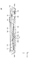
- FIG. 5 is a cross-sectional view of the input device 100 according to one embodiment taken along the AA cross-sectional line (see FIG. 2).
- FIG. 6 is a cross-sectional view along the BB cross-sectional line (see FIG. 2) of the input device 100 according to one embodiment.
- the input device 100 includes a housing 110, a reversing spring 120, a stem 130, and an insulator 140.
- the housing 110 has a thin rectangular parallelepiped shape in the vertical direction (Z-axis direction), and is a horizontally long rectangle whose longitudinal direction is the horizontal direction (Y-axis direction) when viewed from above (positive Z-axis direction). It is a resin container-shaped member having a shape.
- the housing 110 has a first recess 111 that is recessed downward from the upper surface 110A.
- the first concave portion 111 has a substantially oblong rectangular shape in a plan view from above (positive direction of the Z-axis).
- a second recess 112 having a shape recessed further downward is formed on the inner bottom surface on the right side (Y-axis positive side) of the first recess 111 .
- the second concave portion 112 has a circular shape when viewed from above (positive direction of the Z-axis).
- a reversing spring 120 is arranged in the second recess 112 .
- a first fixed contact 113 is provided at the center of the inner bottom surface of the second recess 112 .
- a support portion 114 is provided at the bottom portion on the left side (Y-axis negative side) and front side (X-axis positive side) of the first concave portion 111 .
- the support portion 114 has a metallic disk-shaped second fixed contact 114A.
- Support portion 114 supports fulcrum portion 134 provided on the back surface of stem 130 by the upper surface of second fixed contact 114A.
- the height position of the second fixed contact 114A is higher than the inner bottom surface of the first recess 111 so that the stem 130 can be horizontally supported by the upper surface of the second fixed contact 114A.
- third fixed contacts 115A to 115D are arranged side by side (see FIG. 7) on the left side (Y-axis positive side) and rear-front side (X-axis negative side) bottoms of the first recess 111.
- a pressure sensor 150 is arranged on the four third fixed contacts 115A to 115D. Pressure sensor 150 is electrically connected to each of the four third fixed contacts 115A-115D.
- the pressure sensor 150 has an upwardly convex pressing portion 151 . When the pressing portion 151 is pressed, the pressure sensor 150 can detect the operation load associated with the pressing.
- the reversing spring 120 is a dome-shaped member formed from a thin metal plate and convex upward (in the positive direction of the Z-axis).
- the reversing spring 120 has a circular shape in plan view from above (positive direction of the Z-axis).
- the reversing spring 120 has a dome shape with a top portion 120A at its central portion (that is, the center of the circle).
- a top portion 120A of the reversing spring 120 is formed with a circular opening 121 when viewed from above (the positive direction of the Z-axis).
- the reversing spring 120 is arranged in the second concave portion 112 of the housing 110 .
- the apex 120A of the reversing spring 120 is pushed downward by the operating portion 131 of the stem 130, and when a predetermined operating load is exceeded, the apex 120A is suddenly elastically deformed into a concave shape (reversing operation). do.
- the reversing spring 120 can give a click feeling to the pressing operation.
- the reversing spring 120 returns to its original convex shape due to its elastic force when the pressing force from the stem 130 is released.
- the stem 130 is a plate-like member made of metal having conductivity.
- the stem 130 has substantially the same shape as the first concave portion 111 of the housing 110 (that is, substantially horizontally long rectangular shape) when viewed from above (in the positive Z-axis direction).
- the stem 130 is arranged across the top portion 120A of the reversing spring 120 and the pressing portion 151 of the pressure sensor 150 in the first concave portion 111 of the housing 110 .
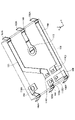
- the stem 130 has an operating portion 131 , a first pressing portion 132 , a second pressing portion 133 and a fulcrum portion 134 .
- the operating portion 131 is formed on the upper surface of the stem 130 (at a position biased to the left side in the Y-axis direction (negative Y-axis direction) and at the center in the X-axis direction), and extends upward (in the positive Z-axis direction). It has a protruding truncated cone shape.
- the operation portion 131 is a portion to which an operation load of a pressing operation is applied from above.
- the first pressing portion 132 is provided on the rear surface of the stem 130 at a position facing the top portion 120A of the reversing spring 120 (a position biased to the right side (positive side of the Y axis) in the Y axis direction and at the center in the X axis direction). It is a truncated conical portion that protrudes downward (in the negative direction of the Z axis).
- the first pressing portion 132 presses the top portion 120A of the reversing spring 120 .
- the protrusion 132A enters the opening 121 of the reversing spring 120. As shown in FIG. A lower end surface of the protrusion 132A protrudes slightly downward from the opening 121 . Thereby, the lower end surface of the protrusion 132A can come into contact with the first fixed contact 113 when the reversing spring 120 is reversed.
- the second pressing portion 133 is positioned on the rear surface of the stem 130 so as to face the pressing portion 151 of the pressure sensor 150 provided in the housing 110 (a position biased to the left in the Y-axis direction (positive side of the Y-axis), and , a position biased toward the rear side in the X-axis direction (negative side of the X-axis), and is a disk-shaped portion that protrudes downward (negative direction of the Z-axis).
- the second pressing portion 133 presses the pressing portion 151 of the pressure sensor 150 .
- the fulcrum portion 134 is located on the rear surface of the stem 130 at a position facing the support portion 114 provided on the housing 110 (a position biased to the left side in the Y-axis direction (positive side of the Y-axis) and to the front side in the X-axis direction). (Position biased toward the positive side of the X-axis), and is a disk-shaped portion protruding downward (negative direction of the Z-axis).
- the fulcrum portion 134 is supported by the support portion 114 provided on the housing 110 and serves as a fulcrum when the stem 130 is tilted by the pressing operation.
- the insulator 140 is a transparent and thin film member.
- the insulator 140 has the same oblong rectangular shape as the upper surface 110A of the housing 110 when viewed from above (positive Z-axis direction). Insulator 140 is adhered (for example, laser welded) to upper surface 110A of housing 110 (the portion surrounding first concave portion 111) so as to entirely cover upper surface 110A of housing 110. As shown in FIG. Insulator 140 can prevent water from entering first recess 111 of housing 110 by sealing first recess 111 of housing 110 .
- FIG. 7 is a diagram showing the configuration of a plurality of fixed contact members included in housing 110 according to one embodiment. As shown in FIG. 7, housing 110 is integrally provided with six fixed contact members 161 to 166 by insert molding. Each fixed contact member is formed using a conductive metal plate.
- the housing 110 is provided with three external connection terminals 161A, 162A, and 163A projecting outward from the right side surface (the side surface on the Y-axis positive side) of the housing 110.
- External connection terminals 164A, 165A, and 166A are provided so as to protrude outward from the left side surface (the side surface on the Y-axis negative side) of the housing 110 .
- the fixed contact member 161 has an external connection terminal 161A at one end and a third fixed contact 115C at the other end.
- a pressure sensor 150 is connected to the third fixed contact 115C.
- the fixed contact member 162 has an external connection terminal 162A at one end and the first fixed contact 113 at the other end.
- the stem 130 When the stem 130 is pressed, the lower end surface of the projecting portion 132A of the stem 130 comes into contact with the first fixed contact 113 .
- the fixed contact member 163 has an external connection terminal 163A at one end and a third fixed contact 115D at the other end.
- a pressure sensor 150 is connected to the third fixed contact 115D.
- the fixed contact member 164 has an external connection terminal 164A at one end and a second fixed contact 114A at the other end.
- the second fixed contact 114A is electrically connected to and supports the stem 130 .
- the fixed contact member 165 has an external connection terminal 165A at one end and a third fixed contact 115A at the other end.
- a pressure sensor 150 is connected to the third fixed contact 115A.
- the fixed contact member 166 has an external connection terminal 166A at one end and a third fixed contact 115B at the other end.
- a pressure sensor 150 is connected to the third fixed contact 115B.
- the input device 100 can detect the operation load of the pressing operation in real time by the pressure sensor 150 .
- the input device 100 can give a click feeling to the pressing operation.
- the input device 100 establishes continuity between the first fixed contact 113 and the external connection terminal 162A and the second fixed contact 114A and the external connection terminal 164A via the stem 130 (that is, switch-on state).
- the reversing spring 120 returns to its original convex shape due to the elastic force of the reversing spring 120 when the pressing operation of the stem 130 on the operating portion 131 is released.
- the contact between the lower end surface of the protrusion 132A of the stem 130 and the first fixed contact 113 is released.
- the first fixed contact 113 and the external connection terminal 162A are disconnected from the second fixed contact 114A and the external connection terminal 164A (that is, the switch is turned off). can be switched.
- the input device 100 it is possible to give a click operation feeling to a pressing operation with a relatively simple configuration, and to detect various kinds of pressing operations (between the ON state and the OFF state). detection of switching and detection of operation load) can be performed.
- FIG. 8 is a diagram showing the operating position, pressing position, and fulcrum position of the stem 130 according to one embodiment.
- the stem 130 has a protrusion 132A that penetrates the opening 121 of the reversing spring 120 and contacts the first fixed contact 113 when the reversing spring 120 is reversed.
- the input device 100 can use the stem 130 as part of the on/off switching switch, and thus can realize the on/off switching switch with a relatively simple configuration.
- the input device 100 since the input device 100 according to one embodiment achieves electrical continuity through simple contact between the protrusion 132A and the first fixed contact 113 without reversing contact of the reversing spring 120, a stable switching operation can be achieved. Prolongation can be realized.
- the stem 130 has an operating portion 131 to which an operating load is applied.
- the input device 100 can clarify the position of the stem 130 to which the operation load should be applied, and thus can obtain a predetermined pressing operation load.
- the housing 110 is provided with a support portion 114 (that is, a fulcrum position) that supports the stem 130 .
- a support portion 114 that is, a fulcrum position
- the stem 130 is tilted around the support portion 114 (and the second pressing portion 133) as a fulcrum.
- the top 120A of the reversing spring 120 can be pressed.
- the stem 130 when an operation load is applied to the operation portion 131, the stem 130 easily presses the top portion 120A of the reversing spring 120 and the pressing portion 151 of the pressure sensor 150 at the same time. be able to.
- the operating portion 131 (that is, the operating position) of the stem 130 is positioned in the first direction (Y-axis direction) in which the top portion 120A of the reversing spring 120 and the support portion 114 are aligned. is provided between the top portion 120A of and the support portion 114.
- the input device 100 can increase the pressing operation load compared to the case where the operation portion 131 is provided on the top portion 120A of the reversing spring 120 .
- the input device 100 according to one embodiment can increase the pressing operation load while suppressing the spring force of the reversing spring 120 itself, so that the life of the reversing spring 120 can be extended.
- the ratio between the first distance L1 from the support portion 114 to the operation portion 131 and the second distance L2 from the support portion 114 to the first pressing portion 132 in the Y-axis direction is 1:5.
- the input device 100 can increase the pressing operation load by five times compared to the case where the operation portion 131 is provided on the top portion 120A of the reversing spring 120 .
- the input device 100 adjusts the position of the operation unit 131 to adjust the ratio between the first distance L1 and the second distance L2, thereby arbitrarily adjusting the pressing operation load. be able to.
- the support portion 114 has a second fixed contact 114A to which the stem 130 is always connected.
- the stem 130 further contacts the second fixed contact 114A and the first fixed contact 113 via the stem 130 by the projection 132A coming into contact with the first fixed contact 113. to conduct electricity between
- the input device 100 can use the stem 130 and the second fixed contact 114A as part of the on/off switching switch, thereby realizing the on/off switching switch with a relatively simple configuration. be able to.
- the operating portion 131 of the stem 130 includes a first pressing portion 132 that presses the top portion 120A of the reversing spring 120 and a pressing portion 151 of the pressure sensor 150 when the stem 130 is viewed from above. It is provided within a triangular area A1 formed by the second pressing portion 133 that presses and the fulcrum portion 134 supported by the supporting portion 114 .
- the input device 100 can stably support the stem 130 at three points and increase the pressing operation load.
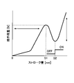
- FIG. 9 is a diagram showing an example of operation load characteristics of the input device 100 according to one embodiment.
- FIG. 9 is a graph showing the operation load characteristics (FS curve) of the input device 100 according to one embodiment. ” is shown.
- the operating load characteristic shown in FIG. 9 is produced by the reversing spring 120 .
- the reversing spring 120 is pressed until the stroke amount of the pressing operation reaches the stroke amount S1 at which the reversing operation of the reversing spring 120 starts.
- the operation load associated with the pressing operation by the operation portion 131 gradually increases. Therefore, as shown in FIG. 9, the operation load associated with the pressing operation by the operation unit 131 becomes the maximum load when the stroke amount of the pressing operation is the stroke amount S1.
- the input device 100 can give a click feeling to the pressing operation.
- the lower end surface of the projecting portion 132A of the stem 130 contacts the first fixed contact 113 when the stroke amount of the pressing operation reaches the stroke amount S2.
- the input device 100 establishes continuity between the first fixed contact 113 and the external connection terminal 162A and the second fixed contact 114A and the external connection terminal 164A via the stem 130 (that is, switch-on state).
- the pressing operation by the operation unit 131 crushes the reversing spring 120, so the operation load related to the pressing operation by the operation unit 131 is maintained until the stroke amount of the pressing operation reaches the maximum stroke amount S3. , gradually increasing.
- the input device 100 can detect such an operation load that changes according to the stroke amount by the pressure sensor 150 in real time.
- FIG. 10 is an external perspective view of an input device 200 according to another embodiment.
- An input device 200 shown in FIG. 10 is a thin input device that can be operated by pressing, and is used in various electronic devices.
- the input device 200 has a substantially rectangular parallelepiped shape with the X-axis direction as the short side and the Y-axis direction as the long side by combining the housing 210 and the cover member 270 with each other. become a thing.
- the input device 200 has a flat stem 230 arranged in the first concave portion 211 of the housing 210 .
- An operating portion 231 of the stem 230 protrudes upward from an opening 272 of the cover member 270 .
- the input device 200 moves between the top portion 220A of the reversing spring 220 provided in the first housing portion 212 of the housing 210 and the second housing portion of the housing 210.
- Both the pressing portion 251 of the pressure sensor 250 (an example of the “load sensor”) provided in the portion 213 and the pressing portion 251 can be pressed by the stem 230 .
- the input device 200 can reverse the reversing spring 220 to give a click operation feeling to the pressing operation, and the one end side of the housing 210 (Y-axis positive side).
- the external connection terminal 262A of the first fixed contact member 262 protruding from the housing 210 and the external connection terminal 264A of the second fixed contact member 264 protruding from the other end side (Y-axis negative side) of the housing 210 are electrically connected. state (ie switched-on state).
- the input device 200 detects the operation load of the pressing operation by pressing the pressing portion 251 of the pressure sensor 250, and a detection signal indicating the detected operation load is provided on the bottom surface 250A of the pressure sensor 250. can be output from four external connection terminals 252A, 252B, 252C, and 252D.
- FIG. 11 and 12 are exploded perspective views of an input device 200 according to another embodiment.
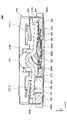
- FIG. 13 is a perspective cross-sectional view of an input device 200 according to another embodiment.
- the input device 200 includes a housing 210, a reversing spring 220, a stem 230, an insulator 240, a pressure sensor 250, and a cover member 270.
- the housing 210 has a thin rectangular parallelepiped shape in the vertical direction (Z-axis direction), and is a horizontally long rectangle whose longitudinal direction is the horizontal direction (Y-axis direction) when viewed from above (the Z-axis positive direction). It is a resin container-shaped member having a shape.
- the housing 210 has a first recess 211 that is recessed downward from the upper surface 210A.
- the first concave portion 211 has a substantially oblong rectangular shape in a plan view from above (positive direction of the Z-axis).
- a first accommodating portion 212 having a shape concaved further downward from the bottom portion 211A of the first concave portion 211 is formed.
- the first accommodating portion 212 has the same shape as the outer shape of the reversing spring 220 (that is, a shape obtained by cutting a part of the circular shape (both sides in the X-axis direction) in a plan view from above (positive direction of the Z-axis). ).
- a reversing spring 220 is arranged in the first accommodating portion 212 .
- a first fixed contact 262B is provided at the center of the bottom of the first accommodating portion 212 .
- a second fixed contact 264B is provided on the periphery of the bottom of the first housing portion 212 .
- a second housing portion 213 On the left side (Y-axis negative side) of the first recess 211, a second housing portion 213 having a shape recessed further downward from the bottom portion 211A of the first recess 211 is provided.
- the second housing portion 213 has the same shape (that is, a rectangular shape) as the outer shape of the pressure sensor 250 in a plan view from above (positive Z-axis direction).
- a pressure sensor 250 is arranged in the second housing portion 213 .
- the housing 210 is integrally provided with the first fixed contact member 262 and the second fixed contact member 264 by insert molding.
- the first fixed contact member 262 has an external connection terminal 262A at one end and a first fixed contact 262B at the other end.
- the second fixed contact member 264 has an external connection terminal 264A at one end and a second fixed contact 264B at the other end. The outer peripheral edge of the reversing spring 220 is always in contact with the second fixed contact 264B.
- the reversing spring 220 is a dome-shaped member that is formed from a conductive thin metal plate and that protrudes upward (in the positive Z-axis direction).
- the reversing spring 220 has a shape in which a part (both sides in the X-axis direction) of a circular shape is cut in plan view from above (positive direction of the Z-axis).
- the reversing spring 220 has a dome shape with a top portion 220A at its central portion (that is, the center of the circle).
- the reversing spring 220 is arranged in the first housing portion 212 of the housing 210 .
- the top portion 220A of the reversing spring 220 is pressed downward by the first pressing portion 232 of the stem 230, and when a predetermined operating load is exceeded, the top portion 220A suddenly becomes concave. It deforms elastically (inverts). Thereby, the reversing spring 220 can give a click feeling to the pressing operation. Further, the reversing spring 220 returns to its original convex shape due to its elastic force when the pressing force from the stem 230 is released.
- the reversing spring 220 can adjust the operating load by adjusting the number of metal plates.
- the reversing spring 220 is configured by stacking three metal plates.
- the present invention is not limited to this, and the reversing spring 220 may be composed of two or less metal plates, or may be composed of four or more metal plates.
- the stem 230 is a flat member.
- the stem 230 has substantially the same shape as the first concave portion 211 of the housing 210 (that is, substantially horizontally long rectangular shape (longitudinal shape)) when viewed from above (positive Z-axis direction).
- the stem 230 is arranged across the top portion 220A of the reversing spring 220 and the pressing portion 251 of the pressure sensor 250 in the first concave portion 211 of the housing 210 .
- the stem 230 has an operating portion 231 , a first pressing portion 232 and a second pressing portion 233 .
- the operating portion 231 is formed in the central portion in the longitudinal direction (Y-axis direction) of the stem 230, and has a convex shape bent upward (in the positive Z-axis direction).
- the operation portion 231 is a portion to which an operation load of a pressing operation is applied from above.
- the first pressing portion 232 is a plate-like portion provided on the Y-axis positive side of the operating portion 231 .
- the back surface of the first pressing portion 232 contacts the top portion 241A of the raised portion 241 of the insulator 240 .
- the first pressing portion 232 moves the reversing spring 220 through the pressing body 242 adhered to the back side portion of the raised portion 241 of the insulator 240 .
- the top 220A can be pressed.
- the second pressing portion 233 is a plate-like portion provided on the Y-axis negative side of the operation portion 231 .
- the first pressing portion 232 contacts the pressing portion 251 of the pressure sensor 250 on its back surface. Thereby, the second pressing portion 233 can press the pressing portion 251 of the pressure sensor 250 when the operation load of the pressing operation is applied to the operating portion 231 .
- Stem 230 is supported from below by apex 241A of protruding portion 241 of insulator 240 (and apex 220A of reversing spring 220) and pressing portion 251 of pressure sensor 250, thereby allowing operating portion 231 to perform a pressing operation. is applied, the point of contact between the second pressing portion 233 and the pressing portion 251 (that is, the top portion) of the pressure sensor 250 is the fulcrum 233A (see FIG. 13), and the first pressure portion It can be tilted downward so that the pressing part 232 is located on the lower side.
- the stem 230 is formed using a hard material so that it is hardly elastically deformed. Thereby, the operator can obtain a direct pressing operation feeling of the reversing spring 220 by the pressing operation of the operation portion 231 .
- the stem 230 does not need to be conductive, it can be formed using either a conductive material (for example, a metal material) or a non-conductive material (for example, a resin material). good too.
- a conductive material for example, a metal material
- a non-conductive material for example, a resin material
- the insulator 240 is a thin sheet-like member arranged on the bottom 211A of the first recess 211 of the housing 210 .
- the insulator 240 is formed using a resin material such as PA.
- the insulator 240 is adhered (for example, laser-welded) to the bottom 211A of the first recess 211 of the housing 210 (the portion surrounding the first housing 212) so as to entirely cover the first housing 212 of the housing 210. ) is done.
- the insulator 240 seals the first housing portion 212 by closing the upper opening of the first housing portion 212 of the housing 210 .
- a central portion of the insulator 240 is formed with a raised portion 241 that protrudes upward (in the positive Z-axis direction).
- a pressing body 242 is adhered to the rear side of the raised portion 241 .
- the pressing body 242 is a member made of resin that presses the top portion 220A of the reversing spring 220 .
- the pressure sensor 250 is arranged below the second pressing portion 233 of the stem 230 inside the second accommodating portion 213 of the housing 210 .
- the pressure sensor 250 has an upwardly convex pressing portion 251 .
- the pressure sensor 250 can detect the operation load of the pressing operation of the stem 230 when the pressing portion 251 is pressed by the second pressing portion 233 of the stem 230 .
- the pressure sensor 250 can output a detection signal indicating the detected operating load from four external connection terminals 252A, 252B, 252C, and 252D provided on the bottom surface 250A of the pressure sensor 250 .
- the cover member 270 is a metal member that covers the upper surface 210A of the housing.
- the cover member 270 has a top wall portion 270B and four side wall portions 270C, and has a rectangular parallelepiped shape with an opening 270A at the bottom.
- the housing 210 is inserted inside the cover member 270 through the opening 270A. Thereby, the housing 210 is arranged inside the cover member 270 .
- cover member 270 covers upper surface 210A of housing 210 and each side surface of housing 210 .
- An upper wall portion 270B of the cover member 270 is provided with a pair of left and right elastic arm portions 271-1 and 271-2.
- Each of the elastic arms 271-1 and 271-2 has a distal end supported by the upper wall 270B and has a tongue-like shape inclined downward from the upper wall 270B. ) can be elastically deformed.
- the elastic arm portion 271-1 is provided above the first pressing portion 232 of the stem 230.
- the elastic arm portion 271-1 presses the first pressing portion 232 of the stem 230 from above at its distal end. Thereby, the elastic arm portion 271 - 1 presses the first pressing portion 232 of the stem 230 against the top portion 220 A of the reversing spring 220 .
- the elastic arm portion 271-2 is provided above the second pressing portion 233 of the stem 230.
- the elastic arm portion 271-2 presses the second pressing portion 233 of the stem 230 from above at its distal end.
- the elastic arm portion 271 - 2 presses the second pressing portion 233 of the stem 230 against the pressing portion 251 of the pressure sensor 250 .
- An opening 272 is formed in the center of the upper wall portion 270B of the cover member 270 .
- the opening 272 allows the operation portion 231 of the stem 230 to pass through and project the operation portion 231 of the stem 230 above the upper wall portion 270B of the cover member 270 .
- the cover member 270 is formed integrally with the upper wall portion 270B, the four side wall portions 270C, and the elastic arm portions 271-1 and 271-2 by processing a single metal plate. be done.
- FIGS. 14A and 14B are diagrams for explaining the operation of the input device 200 according to another embodiment.
- the stem 230 when the operating portion 231 of the stem 230 is not pressed, the stem 230 is positioned at the top portion 241A (and the inverted portion) of the raised portion 241 of the insulator 240 . It is kept horizontal by being supported from below by the top portion 220A of the spring 220 and the pressing portion 251 of the pressure sensor 250 .
- the stem 230 is pressed from above by the elastic arms 271-1 and 271-2 of the cover member 270, so that the apex 241A of the raised portion 241 of the insulator 240 and the pressing portion 251 of the pressure sensor 250 are pressed together. being pushed.
- the input device 200 can prevent the stem 230 from rattling within the first concave portion 211 of the housing 210 .
- the input device 200 can always apply a constant load to the pressing portion 251 of the pressure sensor 250. Therefore, by monitoring the output of the pressure sensor 250, the disconnection can be detected. and other failures can be detected.
- the input device 200 can press the pressure sensor 250 against the bottom portion of the second housing portion 213 of the housing 210 , so that the inside of the second housing portion 213 of the housing 210 can be pushed. , it is possible to suppress the pressure sensor 250 from rattling.
- the input device 200 can detect the operation load of the pressing operation by the pressure sensor 250 in real time.
- the input device 200 can give a click feeling to the pressing operation.
- the input device 200 when the reversing spring 220 is reversed, the back side portion of the top portion 220A of the reversing spring 220 contacts the first fixed contact 262B.
- the input device 200 establishes a conductive state between the first fixed contact 262B and the external connection terminal 262A and the second fixed contact 264B and the external connection terminal 264A via the reversing spring 220. (ie, switch-on state).
- the reversing spring 220 returns to its original convex shape due to the elastic force of the reversing spring 220 when the pressing operation of the stem 230 on the operating portion 231 is released. Thereby, the contact between the back side portion of the top portion 220A of the reversing spring 220 and the first fixed contact 262B is released. As a result, in the input device 200 according to another embodiment, the first fixed contact 262B and the external connection terminal 262A are disconnected from the second fixed contact 264B and the external connection terminal 264A (that is, the switch-off state). ).
- the input device 200 with a relatively simple configuration, it is possible to give a click operation feeling to a pressing operation, and to detect various pressing operations (on state and off state). detection of switching between and detection of operation load) can be performed.
- FIG. 15 is an external perspective view of an input device 200 according to another embodiment, viewed from the bottom side.
- the bottom of the second housing portion 213 of the housing 210 is an opening 213A.
- the second fixed contact member 264 has a narrow portion 264C whose width in the X-axis direction is partially narrow. It is set across the Accordingly, in the input device 200 according to another embodiment, the bottom surface 250A of the pressure sensor 250 accommodated in the second accommodation portion 213 can be supported by the narrow portion 264C of the second fixed contact member 264.
- the input device 200 is configured so that the narrow portion 264C of the second fixed contact member 264 straddles a portion of the opening 213A (the central portion in the X-axis direction).
- Each of the four external connection terminals 252A, 252B, 252C, 252D provided on the bottom surface 250A of the pressure sensor 250 can be exposed from other portions of the opening 213A (portions not having the narrow portion 264C). . Therefore, in the input device 200 according to another embodiment, each of the external connection terminals 252A, 252B, 252C, and 252D can be easily connected to the terminals on the substrate when the input device 200 is mounted on the substrate. can do.
Landscapes
- Switches With Compound Operations (AREA)
- Push-Button Switches (AREA)
Priority Applications (3)
| Application Number | Priority Date | Filing Date | Title |
|---|---|---|---|
| CN202280040220.XA CN117425943A (zh) | 2021-06-25 | 2022-06-22 | 输入装置 |
| JP2023530081A JP7476429B2 (ja) | 2021-06-25 | 2022-06-22 | 入力装置 |
| US18/535,098 US12537149B2 (en) | 2021-06-25 | 2023-12-11 | Input device |
Applications Claiming Priority (2)
| Application Number | Priority Date | Filing Date | Title |
|---|---|---|---|
| JP2021-105457 | 2021-06-24 | ||
| JP2021105457 | 2021-06-25 |
Related Child Applications (1)
| Application Number | Title | Priority Date | Filing Date |
|---|---|---|---|
| US18/535,098 Continuation US12537149B2 (en) | 2021-06-25 | 2023-12-11 | Input device |
Publications (1)
| Publication Number | Publication Date |
|---|---|
| WO2022270528A1 true WO2022270528A1 (ja) | 2022-12-29 |
Family
ID=84545743
Family Applications (1)
| Application Number | Title | Priority Date | Filing Date |
|---|---|---|---|
| PCT/JP2022/024839 Ceased WO2022270528A1 (ja) | 2021-06-25 | 2022-06-22 | 入力装置 |
Country Status (4)
| Country | Link |
|---|---|
| US (1) | US12537149B2 (https=) |
| JP (1) | JP7476429B2 (https=) |
| CN (1) | CN117425943A (https=) |
| WO (1) | WO2022270528A1 (https=) |
Families Citing this family (1)
| Publication number | Priority date | Publication date | Assignee | Title |
|---|---|---|---|---|
| WO2025260775A1 (en) * | 2024-06-20 | 2025-12-26 | Razer (Asia-Pacific) Pte. Ltd. | Analog load sensing arrangement |
Citations (2)
| Publication number | Priority date | Publication date | Assignee | Title |
|---|---|---|---|---|
| JP2018160318A (ja) * | 2017-03-22 | 2018-10-11 | パナソニックIpマネジメント株式会社 | 入力装置の製造方法、操作部品、及び入力装置 |
| WO2021010064A1 (ja) * | 2019-07-17 | 2021-01-21 | パナソニックIpマネジメント株式会社 | 入力装置、及び入力システム |
Family Cites Families (5)
| Publication number | Priority date | Publication date | Assignee | Title |
|---|---|---|---|---|
| JP3179036U (ja) | 2012-08-01 | 2012-10-11 | アルプス電気株式会社 | プッシュスイッチ |
| JP7125492B2 (ja) * | 2018-09-06 | 2022-08-24 | アルプスアルパイン株式会社 | プッシュスイッチ |
| WO2021070660A1 (ja) * | 2019-10-10 | 2021-04-15 | パナソニックIpマネジメント株式会社 | 入力装置 |
| WO2021166478A1 (ja) * | 2020-02-17 | 2021-08-26 | アルプスアルパイン株式会社 | プッシュスイッチ |
| CN115699237A (zh) * | 2020-06-04 | 2023-02-03 | 阿尔卑斯阿尔派株式会社 | 按压开关及按压开关系统 |
-
2022
- 2022-06-22 JP JP2023530081A patent/JP7476429B2/ja active Active
- 2022-06-22 CN CN202280040220.XA patent/CN117425943A/zh active Pending
- 2022-06-22 WO PCT/JP2022/024839 patent/WO2022270528A1/ja not_active Ceased
-
2023
- 2023-12-11 US US18/535,098 patent/US12537149B2/en active Active
Patent Citations (2)
| Publication number | Priority date | Publication date | Assignee | Title |
|---|---|---|---|---|
| JP2018160318A (ja) * | 2017-03-22 | 2018-10-11 | パナソニックIpマネジメント株式会社 | 入力装置の製造方法、操作部品、及び入力装置 |
| WO2021010064A1 (ja) * | 2019-07-17 | 2021-01-21 | パナソニックIpマネジメント株式会社 | 入力装置、及び入力システム |
Also Published As
| Publication number | Publication date |
|---|---|
| JP7476429B2 (ja) | 2024-04-30 |
| US12537149B2 (en) | 2026-01-27 |
| US20240234051A9 (en) | 2024-07-11 |
| CN117425943A (zh) | 2024-01-19 |
| JPWO2022270528A1 (https=) | 2022-12-29 |
| US20240136128A1 (en) | 2024-04-25 |
Similar Documents
| Publication | Publication Date | Title |
|---|---|---|
| US4197437A (en) | Snap-action switch | |
| CN215451206U (zh) | 可动构件以及输入装置 | |
| WO2022270528A1 (ja) | 入力装置 | |
| US7745744B2 (en) | Multidirectional switch | |
| US11430618B2 (en) | Push switch | |
| JP2016081915A (ja) | プッシュスイッチ | |
| JP6632938B2 (ja) | プッシュスイッチ | |
| WO2021246105A1 (ja) | プッシュスイッチ、及び、プッシュスイッチシステム | |
| US20210125800A1 (en) | Push switch | |
| JP6990832B2 (ja) | プッシュスイッチ | |
| US12094665B2 (en) | Push switch | |
| US11984277B2 (en) | Push switch | |
| CN216119989U (zh) | 一种轻触开关 | |
| CN117747330A (zh) | 开关 | |
| CN120020986A (zh) | 按压开关 | |
| CN223665341U (zh) | 按压开关 | |
| JP7383199B2 (ja) | スイッチ装置 | |
| JP2022043622A (ja) | プッシュスイッチ | |
| CN114787953A (zh) | 按压开关的推压机构及按压开关 | |
| US20250329505A1 (en) | Double pole double throw switch | |
| US20250391620A1 (en) | Pressing operation unit and switching device | |
| US20250125100A1 (en) | Push switch | |
| JP7519624B2 (ja) | プッシュスイッチ | |
| WO2024157998A1 (ja) | プッシュスイッチ | |
| WO2025142106A1 (ja) | プッシュスイッチ |
Legal Events
| Date | Code | Title | Description |
|---|---|---|---|
| 121 | Ep: the epo has been informed by wipo that ep was designated in this application |
Ref document number: 22828444 Country of ref document: EP Kind code of ref document: A1 |
|
| WWE | Wipo information: entry into national phase |
Ref document number: 2023530081 Country of ref document: JP |
|
| WWE | Wipo information: entry into national phase |
Ref document number: 202280040220.X Country of ref document: CN |
|
| NENP | Non-entry into the national phase |
Ref country code: DE |
|
| 122 | Ep: pct application non-entry in european phase |
Ref document number: 22828444 Country of ref document: EP Kind code of ref document: A1 |