WO2022270464A1 - 鉛蓄電池用補水栓、鉛蓄電池、組電池 - Google Patents
鉛蓄電池用補水栓、鉛蓄電池、組電池 Download PDFInfo
- Publication number
- WO2022270464A1 WO2022270464A1 PCT/JP2022/024533 JP2022024533W WO2022270464A1 WO 2022270464 A1 WO2022270464 A1 WO 2022270464A1 JP 2022024533 W JP2022024533 W JP 2022024533W WO 2022270464 A1 WO2022270464 A1 WO 2022270464A1
- Authority
- WO
- WIPO (PCT)
- Prior art keywords
- discharge hole
- lead
- water
- valve
- acid battery
- Prior art date
- Legal status (The legal status is an assumption and is not a legal conclusion. Google has not performed a legal analysis and makes no representation as to the accuracy of the status listed.)
- Ceased
Links
Images






Classifications
-
- H—ELECTRICITY
- H01—ELECTRIC ELEMENTS
- H01M—PROCESSES OR MEANS, e.g. BATTERIES, FOR THE DIRECT CONVERSION OF CHEMICAL ENERGY INTO ELECTRICAL ENERGY
- H01M50/00—Constructional details or processes of manufacture of the non-active parts of electrochemical cells other than fuel cells, e.g. hybrid cells
- H01M50/60—Arrangements or processes for filling or topping-up with liquids; Arrangements or processes for draining liquids from casings
- H01M50/609—Arrangements or processes for filling with liquid, e.g. electrolytes
- H01M50/627—Filling ports
- H01M50/636—Closing or sealing filling ports, e.g. using lids
- H01M50/645—Plugs
-
- Y—GENERAL TAGGING OF NEW TECHNOLOGICAL DEVELOPMENTS; GENERAL TAGGING OF CROSS-SECTIONAL TECHNOLOGIES SPANNING OVER SEVERAL SECTIONS OF THE IPC; TECHNICAL SUBJECTS COVERED BY FORMER USPC CROSS-REFERENCE ART COLLECTIONS [XRACs] AND DIGESTS
- Y02—TECHNOLOGIES OR APPLICATIONS FOR MITIGATION OR ADAPTATION AGAINST CLIMATE CHANGE
- Y02E—REDUCTION OF GREENHOUSE GAS [GHG] EMISSIONS, RELATED TO ENERGY GENERATION, TRANSMISSION OR DISTRIBUTION
- Y02E60/00—Enabling technologies; Technologies with a potential or indirect contribution to GHG emissions mitigation
- Y02E60/10—Energy storage using batteries
Definitions
- the present invention relates to a technique for replenishing water in the container of a lead-acid battery.
- Patent Document 1 describes a water faucet for a storage battery that has an automatic water stop function.
- the water supply valve for a storage battery of Patent Document 1 has a float that moves up and down following the liquid surface of the electrolyte, a disc-shaped valve (valve element) connected to the float, and a valve chamber that houses the valve element. doing.
- the valve chest has an inflow port (introduction port) as an upstream opening, and a refilling water port (outlet) as a downstream opening.
- the water that flows into the valve chamber from the inlet flows out from the outlet and replenishes the battery tank.
- the valve body connected to the float closes the discharge port to stop the water supply, and refilling of water is stopped.
- Turbulence may occur inside the valve chamber. Turbulent flow affects the opening and closing action of the valve body, causing “early closing” in which the outlet closes even though water is not sufficiently replenished, and “late closing” in which the outlet does not close even though water has already been sufficiently replenished. Become. In addition, when turbulence occurs, the water pressure drops due to pressure loss, so the flow rate decreases and it takes time to replenish the water tank.
- the present invention has been completed based on the above problems, and discloses a technique for suppressing the occurrence of turbulence in the valve chamber.
- a lead-acid battery water replenishment valve comprises a plug body, a valve chamber located inside the plug body and having a replenisher inlet and a discharge hole, and a valve chamber accommodated in the valve chamber for opening and closing the discharge hole. and the inner peripheral portion of the discharge hole is tapered such that the opening area decreases from the inside to the outside of the valve chamber in a cross section cut along the central axis of the valve chamber passing through the discharge hole. and the introduction port is positioned on an extension of the tapered shape of the inner periphery of the discharge hole in relation to the discharge hole.
- the introduction port is located on the extension line of the tapered shape of the inner periphery of the discharge hole" means that even a part of the introduction port is located on the extension line of the tapered shape.
- the present invention it is possible to suppress the occurrence of turbulence by smoothing the flow of water in the valve chamber, smoothen the opening and closing operation of the valve body, and suppress the decrease in the flow rate.
- a supplementary water tap for a lead-acid battery includes a plug body, a valve chamber located inside the plug body and having an inlet and a discharge hole for a replenisher, and a valve body housed therein for opening and closing the discharge hole, wherein the inner peripheral portion of the discharge hole is the inner circumference of the valve chamber in a cross section cut along the central axis of the valve chamber passing through the discharge hole.
- the inlet has a tapered shape in which the opening area becomes smaller toward the outside, and the introduction port is positioned on an extension of the tapered shape of the inner peripheral portion of the discharge hole in relation to the discharge hole.
- the inner periphery of the discharge hole has a tapered shape
- a water flow flows into the discharge hole along the tapered shape in the vicinity of the discharge hole.
- the replenisher supplied from the inlet flows out into the valve chamber and then joins the water stream flowing into the discharge hole along the tapered shape. do. Therefore, it is possible to create a smooth water flow toward the discharge hole in the valve chamber, thereby suppressing the occurrence of turbulence.
- the effect of turbulence on the opening and closing operation of the valve body can be suppressed, and the opening and closing operation of the valve body can be performed smoothly. Also, suppressing the occurrence of turbulence reduces the pressure loss of the replenisher passing through the valve chamber. As a result, the pressure of the replenisher can be maintained, and the decrease in the flow rate of the replenisher passing through the valve chamber can be suppressed.
- the valve body has a first position in which it is separated from the discharge hole and opened, and a second position in which it contacts and closes the discharge hole. and the inlet may be in a position relative to the valve body that is closer to the outlet hole than the valve body is in the first position.
- the water flow of the replenisher flowing in from the inlet does not interfere with the valve body in the first position, so the water flow does not collide with the valve body and turbulence is less likely to occur.
- the discharge hole penetrates through one wall surface of the valve chamber, and the valve body is disposed in the valve chamber with the discharge hole facing each other and having a hemispherical shape convex toward the discharge hole.
- the valve body has a hemispherical shape with an upward projection, even if the water flow of the replenisher hits it from above, the momentum can be deflected along the spherical surface, and the opening and closing operation is less likely to be hindered.
- the lead-acid battery water faucet according to any one of (1) to (3) above may have an introducing portion that guides a replenisher to the inlet.
- the introduction portion may be parallel to the movement direction of the valve body. Compared to the case where the introduction portion is perpendicular to the moving direction of the valve body, the water flow of the replenisher flowing into the valve chamber from the introduction port does not hinder the movement of the valve body. Therefore, the movement of the valve body becomes smooth, and a good water cutoff property can be ensured.
- the target of the present technology may be a lead-acid battery equipped with a lead-acid battery water faucet according to any one of (1) to (4) above.
- the lead-acid battery water tap of one of the lead-acid batteries includes a lead-acid battery water tap of the other lead-acid battery and a water supply. It may be connected via a tube.
- the replenisher By replenishing the replenisher from one end of the water supply tube, the replenisher can be supplied to each lead-acid battery up to a predetermined value.
- the replenisher can be replenished collectively for multiple lead-acid batteries.
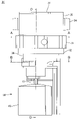
- FIG. 1 is a plan view of an assembled battery 10 used in an electric vehicle such as an electric forklift.
- the assembled battery 10 is composed of 12 lead-acid batteries 11 arranged in 6 horizontal rows and 2 vertical rows inside the battery case 13 .
- a lead-acid battery water faucet (hereinafter also simply referred to as a 'supplementary water faucet') 20 shown in FIG.
- Water taps 20 of adjacent lead-acid batteries 11 are connected via water supply tubes 12 .
- a water tank (not shown) to one end 12a of the water supply tube 12 and pumping water (an example of a "replenisher"), the 12 lead-acid batteries 11 can be supplied with water at once.
- the supplementary water tap 20 will be described below with reference to FIGS. 2 to 11.
- FIG. The supplementary water tap 20 includes a tap main body 30 and a float valve 60. - ⁇
- FIG. 2 is a perspective view of the replenishment tap 20, and FIG. 3 is a front view.
- the plug body 30 is made of synthetic resin such as ABS, and has a substantially cylindrical shape extending in the axial direction. 2 and 3 show a state in which the axial direction of the plug body 30 is oriented vertically.
- a brim portion 31 is the thickest portion in the horizontal direction of the plug body 30 .
- a ring-shaped rubber packing 32 is arranged along the outer circumference of the plug body 30 below the collar portion 31 .
- the rubber packing 32 is in tight contact with both the lower surface of the collar portion 31 and the upper surface of the battery lid to seal around the liquid port.
- the portion of the water replenishing tap 20 closer to the plug lid portion 37 than the rubber packing 32 is exposed above the upper surface of the battery lid, and the other portion is inserted into the liquid port of the battery lid and positioned inside the battery case. .
- a water supply port 33 (see FIG. 8) is provided on the upper surface of the flange portion 31, and a three-pronged water supply pipe joint 34 is connected to the water supply port 33.
- the water supply tubes 12 connected to the water supply pipe joints 34 connect the water supply pipe joints 34 of the adjacent lead-acid batteries 11 to each other.
- a semi-cylindrical portion 35 is erected on the upper surface of the brim portion 31 at a position on the front left side in FIG.
- the upper end of the semi-cylindrical portion 35 forms an opening 35a having a semi-circular opening edge.
- a plug lid portion 37 is connected via a hinge 36 to the chord portion of the opening edge.
- the opening 35a can be opened or closed by rotating the stopper 37 about the hinge 36. As shown in FIG.
- the plug body 30 has three partition walls (first partition wall 41 to third partition wall 43).
- the three partition walls 41-43 are integral with the plug body 30.
- the first partition wall 41 extends substantially parallel to the vertical direction inside the plug body 30 .
- both ends of the first partition 41 are connected to the peripheral wall 38, respectively, and the first partition 41 partitions the internal space of the plug body 30 into two spaces.
- the second partition 42 and the third partition 43 are partitions extending substantially parallel to the vertical direction inside the plug body 30 .
- the second partition 42 and the third partition 43 are arranged in each of the two internal spaces of the plug body 30 partitioned by the first partition 41 .
- the second partition 42 and the third partition 43 extend from the peripheral wall 38 toward the first partition 41 and are connected to the first partition 41 .
- the second partition 42 and the third partition 43 further partition the internal space of the plug body 30 divided into two by the first partition.
- FIG. 6 is a diagram schematically showing the positions of the first partition wall 41 to the third partition wall 43 superimposed on the plan view of the plug body 30.
- the internal space of the replenishment tap 20 partitioned into four by the first partition 41 to the third partition 43 is arranged counterclockwise from the lower right in FIGS. (2) front chamber 45, (3) water stop chamber 46, and (4) refilling chamber 47.
- the space on the side where the front chamber 45 and the water stop chamber 46 are provided is the “second 1 space”
- the space on the side where the refilling chamber 47 and the measurement chamber 44 are provided is the “second space”.
- each of the partitions 41-43 has a gap or a slit, and has a structure in which water can pass through the four divided spaces 44-47.
- the water in the front chamber 45 can flow into the water stop chamber 46 through a gap 52 formed below the end 49a of the first partition 41 (partition wall 49). It has become.
- a slit 39 extending over the water stop chamber 46 and the water replenishing chamber 47 is provided through the first partition wall 41 .
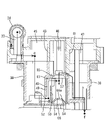
- FIG. 7 is a cross-sectional view along line CC in FIG. Points b to f in FIG. 7 respectively correspond to the positions of points b to f in FIG. 6 on the plan view. Arrows connecting the points in FIGS. 6 and 7 indicate the path of water inside the water retaining valve. The spaces 44 to 47 and the paths of water will be described below.
- the water supplied from the water supply tube 12 to the water supply port 33 passes through the water path inside the water replenishing valve, reaches the replenishing water chamber 47, and finally refills the battery tank.
- the water supply port 33 side is defined as the upstream side
- the water replenishing chamber 47 side is defined as the downstream side with reference to an arbitrary point in the water path.
- the measurement chamber 44 is a space surrounded by the peripheral wall 38, the first partition 41 and the second partition 42, and is located on the lower right in FIGS.
- the measurement chamber 44 does not have a ceiling surface and a bottom surface, and penetrates the supplementary water faucet 20 in the vertical direction.
- a portion of the measurement chamber 44 closer to the stopper lid portion 37 than the collar portion 31 is part of the internal space of the semi-cylindrical portion 35 .
- the measurement chamber 44 functions as an insertion port into which a specific gravity meter is inserted when measuring the specific gravity of the electrolyte. When a rod-shaped specific gravity meter is inserted into the specific gravity measurement port through the opening 35a of the semi-cylindrical portion 35, the tip of the specific gravity meter reaches the electrolyte, and the specific gravity can be measured.
- the front chamber 45 is a space surrounded by the peripheral wall 38, the first partition 41 and the third partition 43, and is located on the upper right in FIGS.
- the front chamber 45 communicates with the water supply port 33, and the water supplied to the water supply port 33 flows into and temporarily stays therein. Specifically, as shown in FIGS. 6 and 7, water supplied from the water supply tube 12 (point a) passes through the water supply pipe joint 34 (point b) and flows into the front chamber 45 from the water supply port 33. (point c).
- a guide passage 48 is provided at the boundary between the front chamber 45 and the water stop chamber 46, as shown in FIG.
- the guide passage 48 is formed by a partition wall 49 (part of the third partition wall 43) and a side wall 50 of the valve chamber 54.
- Water entering the guide passage 48 from the inlet (point d) flows through the guide passage 48 toward the downstream side, and then passes through an inlet 53 penetrating the upper portion of the side wall 50 of the valve chamber 54 and into the valve chamber 54 . (point e).
- the guide passage 48 is parallel to the moving direction (vertical direction) of the valve body 66 , and water moves through the guide passage 48 from bottom to top and reaches the inlet 53 .
- the guide passage 48 is an introduction portion that introduces water into the introduction port 53 .
- the water stop chamber 46 is a space surrounded by the peripheral wall 38, the first partition 41 and the third partition 43, and is located on the upper left in FIGS.
- the water stop chamber 46 has the guide passage 48 and the valve chamber 54 described above.
- valve chamber 54 is surrounded by a cylindrical side wall 50 whose axis extends in the vertical direction, a ceiling wall 57 and a bottom wall 51 .
- the valve chamber 54 accommodates a valve body 66 which will be described later.
- the valve chamber 54 has an inlet 53 and a discharge hole 55 on one wall surface of the valve chamber 54 .
- the introduction port 53 and the discharge hole 55 are provided through the side wall 50 and the ceiling wall 57, respectively.
- the water that has flowed into the valve chamber 54 from the inlet 53 is discharged from the discharge hole 55 into the space above the valve chamber 54 .
- the water replenishment chamber 47 is a space surrounded by the peripheral wall 38, the first partition 41 and the second partition 42, and is located at the lower left in FIGS. 4 to 6. As shown in FIG. 7, the refilling chamber 47 is open downward.
- the side of the replenishing water chamber 47 on the stopper lid portion 37 side is also the internal space of the semi-cylindrical portion 35 .
- the water flowing out from the discharge hole 55 into the upper space of the valve chamber 54 flows horizontally over the valve chamber 54, enters the replenishing water chamber 47, drops downward, and is replenished into the container (point f).
- FIG. 8 and 9 are DD cross-sectional views of the supplementary water tap 20.
- FIG. The refilling chamber 47 is provided with a pair of guide portions 56 that are vertically spaced apart from each other.
- Each of the pair of guide portions 56 is provided with an insertion hole penetrating in the vertical direction, and a float shaft 61 to be described later is inserted through the insertion hole.
- the float shaft 61 is vertically displaced while being kept substantially vertical by the pair of guide portions 56 .
- FIG. 10 shows an overall view of the float valve 60 .
- the float valve 60 is formed by connecting a float shaft 61, a water stop valve 62 and a float 63 integrally. A portion of the float valve 60 other than the float 63 is housed inside the plug body 30 (see FIG. 2). The float valve 60 is not fixed to the plug body 30 and can move up and down with respect to the plug body 30 .
- the float shaft 61 is supported in the refilling chamber 47 by a pair of guide portions 56 with its axis directed vertically.
- the float shaft 61 extends downward through the second guide portion 56b and protrudes downward from the bottom wall 51 of the plug body 30. As shown in FIG. 8,
- the float shaft 61 has a support portion 64 on its outer peripheral surface.
- the support portion 64 horizontally protrudes from the float shaft 61 between the first guide portion 56a and the second guide portion 56b.
- the support portion 64 penetrates through a slit 39 provided through the first partition wall 41 forming a boundary between the refilling chamber 47 and the water stop chamber 46 .
- the slit 39 is elongated in the vertical direction and functions as a guide groove that guides the vertical movement of the support portion 64 .
- the tip of the support portion 64 extends to the upper space of the valve chamber 54 and supports the water stop valve 62 housed in the valve chamber 54 in a suspended manner.
- the water stop valve 62 consists of a valve shaft 65 and a valve body 66 .
- the valve shaft 65 extends vertically and vertically penetrates the discharge hole 55 .
- the upper end of the valve shaft 65 is fixed to the support portion 64, and the valve body 66 is fixed to the lower end.
- the valve body 66 is accommodated in the valve chamber 54 so as to be vertically movable.
- the valve body 66 is positioned vertically facing each other with respect to the discharge hole 55 .
- the valve body 66 has a hemispherical shape that protrudes toward the discharge hole 55, and the upper surface 66a that contacts the discharge hole 55 is spherical.
- the float 63 is a substantially cylindrical floating body made of hollow or foamed synthetic resin.
- the lower end of the float shaft 61 is inserted into and fixed to the float 63 .
- the float 63 floats on the liquid surface of the electrolytic solution in the container and moves up and down following the liquid surface.
- the buoyancy of the float 63 causes the entire float valve 60 to follow the height of the liquid level and move up and down integrally.
- the range in which the float valve 60 moves up and down is between the lower limit position (Fig. 8) and the upper limit position (Fig. 9).
- the lower limit position is an example of a "first position”
- the upper limit position is an example of a "second position”.
- the water stop valve 62 at the lower limit position is separated from the discharge hole 55 and is in contact with the bottom wall 51, and the discharge hole 55 is open at this time (Fig. 8).
- the refilling tap 20 automatically stops refilling water when the liquid level reaches a predetermined height.
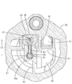
- FIG. 11 is a cross-sectional view (an enlarged view of the vicinity of the valve chamber 54 in FIG. 7) taken along the central axis L of the valve chamber 54 passing through the discharge hole 55.
- the discharge hole 55 vertically penetrates the ceiling wall 57 .
- the inner peripheral portion 55A of the discharge hole 55 has a conical shape, and the cross section has a tapered shape in which the opening area decreases from the inside to the outside of the valve chamber 54 (from the bottom to the top in FIG. 11).
- the introduction port 53 penetrates the side wall 50 in the horizontal direction and communicates the guide passage 48 with the valve chamber 54 .
- the range of the introduction port 53 is indicated by the A dimension.
- the introduction port 53 is positioned on an extension line of the tapered shape of the discharge hole 55 .
- a dashed line 58 in FIG. 11 is an extension of the tapered shape.
- the water flow R from the valve chamber 54 toward the discharge hole 55 flows into the discharge hole 55 along the tapered shape of the discharge hole 55. Since the introduction port 53 is positioned on the extension line 58 of the tapered shape, it can smoothly merge with the water flow R1 flowing into the discharge hole 55 along the tapered shape. As a result, turbulence is suppressed at the position where the water flow R and the water flow Q join, so that the influence of the turbulence on the opening/closing operation of the valve body 66 can be reduced.
- valve chamber 54 pressure loss in the valve chamber 54 is reduced by suppressing turbulence.
- pressure loss is small, the flow rate of water passing through the valve chamber 54 is less likely to decrease, so water can be replenished up to the specified amount in a short period of time.
- the valve chamber 54 has a configuration in which two members, an upper member 71 including a ceiling wall 57 and a lower member 72 including a bottom wall 51 are combined.
- the upper member 71 has a third partition wall 43 hanging down from above, a ceiling wall 57 extending horizontally from the third partition wall 43, and a partition wall 49 hanging down from the ceiling wall 57 and a first side wall 50a.
- the lower member 72 has a horizontally extending bottom wall 51 and a second side wall 50 b vertically rising from the bottom wall 51 .
- the first side wall 50a and the second side wall 50b are both curved in an arc shape in a plan view to form a cylindrical side wall 50 surrounding the valve body 66. As shown in FIG.
- the upper end of the second side wall 50b is cut into a horizontally long rectangular shape.
- the upper end of the second side wall and the ceiling wall are in contact with each other without gaps except for the notched portion, but the notched portion forms a rectangular opening.
- This opening is the introduction port 53 and communicates the valve chamber 54 and the guide passage 48 .
- the valve body 66 is lowered to the bottom wall 51 of the valve chamber 54 at the lower limit position (first position).
- the introduction port 53 is located above the valve body 66 at the lower limit position. Specifically, the lower end 53a of the introduction port 53 is above the upper surface 66a of the valve body 66, and the introduction port 53 does not overlap the valve body 66 at the lower limit position in the vertical direction. Further, as shown in FIG. 11, the introduction port 53 is positioned closer to the discharge hole 55 in the vertical direction than the valve body 66 at the lower limit position.
- the introduction port 55 By disposing the introduction port 55 closer to the discharge hole 55 than the valve body 66 at the lower limit position, the water flow (water flow Q) from the introduction port 53 toward the discharge hole 55 of the valve chamber 54 is reduced to the lower limit position. can merge with the water flow R near the discharge hole 55 without colliding with the valve body 66 at the bottom (non-interference). Therefore, turbulence can be suppressed near the inlet of the discharge hole. This makes it possible to create a smooth water flow from the inlet 53 to the outlet 55 .
- valve body 66 at the lower limit position and the water flow Q do not interfere with each other, it is possible to suppress the water flow Q from pushing the valve body 66 from the lower limit position toward the upper limit position. As a result, premature closing of the valve body 66 can be made difficult to occur.
- the valve body 66 is circular in plan view, and the side wall 50 is cylindrical surrounding the valve body 66 .
- the gap between the valve body 66 and the side wall 50 can be reduced. This makes it difficult for the water flow to flow to the opposite side of the valve body 66 , and prevents the water flow from interfering with the opening/closing operation of the valve body 66 .
- the valve body 66 vertically faces the discharge hole 55 in the valve chamber 54 .
- the valve body 66 has a hemispherical shape convex toward the discharge hole 55.
- the discharge hole 55 is positioned above and the valve body 66 is positioned below.
- valve body 66 has an upwardly convex hemispherical shape, even if a downward water stream hits the upper surface 66a, the force of the water stream can be parried along the spherical surface. Action can be performed.
- the assembled battery 10 used for an electric forklift is exemplified.
- the assembled battery 10 can also be used for an electric trolley, an aerial work vehicle, and the like.
- the application of the assembled battery 10 is not limited to a mobile object such as an electric vehicle. It can also be used for stationary applications such as uninterruptible power supplies and power storage devices for power generation systems.
- the introduction port 53 is provided at a position closer to the upper end of the side wall 50 (50b).
- the introduction port 53 may be a part of the introduction port 53 or may be on the extension line of the tapered shape of the discharge hole 55, for example, it may be located below the position in the above embodiment.
Landscapes
- Chemical & Material Sciences (AREA)
- Chemical Kinetics & Catalysis (AREA)
- Electrochemistry (AREA)
- General Chemical & Material Sciences (AREA)
- Filling, Topping-Up Batteries (AREA)
Priority Applications (2)
| Application Number | Priority Date | Filing Date | Title |
|---|---|---|---|
| JP2023530460A JPWO2022270464A1 (https=) | 2021-06-22 | 2022-06-20 | |
| CN202280043887.5A CN117561647A (zh) | 2021-06-22 | 2022-06-20 | 铅蓄电池用补水栓、铅蓄电池、电池组 |
Applications Claiming Priority (2)
| Application Number | Priority Date | Filing Date | Title |
|---|---|---|---|
| JP2021103063 | 2021-06-22 | ||
| JP2021-103063 | 2021-06-22 |
Publications (1)
| Publication Number | Publication Date |
|---|---|
| WO2022270464A1 true WO2022270464A1 (ja) | 2022-12-29 |
Family
ID=84545691
Family Applications (1)
| Application Number | Title | Priority Date | Filing Date |
|---|---|---|---|
| PCT/JP2022/024533 Ceased WO2022270464A1 (ja) | 2021-06-22 | 2022-06-20 | 鉛蓄電池用補水栓、鉛蓄電池、組電池 |
Country Status (3)
| Country | Link |
|---|---|
| JP (1) | JPWO2022270464A1 (https=) |
| CN (1) | CN117561647A (https=) |
| WO (1) | WO2022270464A1 (https=) |
Citations (3)
| Publication number | Priority date | Publication date | Assignee | Title |
|---|---|---|---|---|
| JPH0222568U (https=) * | 1988-07-27 | 1990-02-15 | ||
| CN102691824A (zh) * | 2012-06-15 | 2012-09-26 | 浙江天能电池(江苏)有限公司 | 定量补水的电池阀 |
| WO2021079525A1 (ja) * | 2019-10-25 | 2021-04-29 | 昭和電工マテリアルズ株式会社 | 補水栓 |
-
2022
- 2022-06-20 WO PCT/JP2022/024533 patent/WO2022270464A1/ja not_active Ceased
- 2022-06-20 CN CN202280043887.5A patent/CN117561647A/zh active Pending
- 2022-06-20 JP JP2023530460A patent/JPWO2022270464A1/ja active Pending
Patent Citations (3)
| Publication number | Priority date | Publication date | Assignee | Title |
|---|---|---|---|---|
| JPH0222568U (https=) * | 1988-07-27 | 1990-02-15 | ||
| CN102691824A (zh) * | 2012-06-15 | 2012-09-26 | 浙江天能电池(江苏)有限公司 | 定量补水的电池阀 |
| WO2021079525A1 (ja) * | 2019-10-25 | 2021-04-29 | 昭和電工マテリアルズ株式会社 | 補水栓 |
Also Published As
| Publication number | Publication date |
|---|---|
| CN117561647A (zh) | 2024-02-13 |
| JPWO2022270464A1 (https=) | 2022-12-29 |
Similar Documents
| Publication | Publication Date | Title |
|---|---|---|
| CN109974273B (zh) | 用于空气处理设备的接水盘组件及空气处理设备 | |
| RU2010138199A (ru) | Трехходовой клапан с устройством для отклонения потока | |
| WO2022270464A1 (ja) | 鉛蓄電池用補水栓、鉛蓄電池、組電池 | |
| CN217876737U (zh) | 液位开关以及具有其的储液装置和冰箱 | |
| WO2022270465A1 (ja) | 鉛蓄電池用補水栓、鉛蓄電池、組電池 | |
| JP6024668B2 (ja) | 蓄電池用補水栓 | |
| CN204712857U (zh) | 冷却液容器 | |
| WO2022270463A1 (ja) | 鉛蓄電池用補水栓、鉛蓄電池、組電池 | |
| CN212956794U (zh) | 一种溢流组件 | |
| CN109099202A (zh) | 液位控制器及其液位控制系统 | |
| CN218628455U (zh) | 一种流量计通水结构 | |
| CN202812777U (zh) | 一种用于液化天然气加气机的浮子式气液分离器 | |
| CN209103160U (zh) | 液位控制器及其液位控制系统 | |
| WO2023098667A1 (zh) | 液位开关以及具有其的储液装置和冰箱 | |
| WO2023098377A1 (zh) | 电解除氧装置以及具有其的冰箱 | |
| CN210135290U (zh) | 浮球阀门及水箱 | |
| CN208165544U (zh) | 一种水封箱 | |
| CN221170988U (zh) | 一种真空破坏阀 | |
| CN111779093B (zh) | 一种隔离空气的溢流系统 | |
| CN209100749U (zh) | 液位控制器及其液位控制系统 | |
| KR200443173Y1 (ko) | 폼 탱크 | |
| CN223358385U (zh) | 一种防虹吸装置及水箱进水装置 | |
| CN223244031U (zh) | 水质检测蓄水箱 | |
| NO811844L (no) | Paafyllingsanordning for elektrolyttbatterier. | |
| CN109616609A (zh) | 电解液导流装置及蓄电池 |
Legal Events
| Date | Code | Title | Description |
|---|---|---|---|
| 121 | Ep: the epo has been informed by wipo that ep was designated in this application |
Ref document number: 22828381 Country of ref document: EP Kind code of ref document: A1 |
|
| WWE | Wipo information: entry into national phase |
Ref document number: 2023530460 Country of ref document: JP |
|
| WWE | Wipo information: entry into national phase |
Ref document number: 2301008286 Country of ref document: TH |
|
| WWE | Wipo information: entry into national phase |
Ref document number: 202280043887.5 Country of ref document: CN |
|
| NENP | Non-entry into the national phase |
Ref country code: DE |
|
| 122 | Ep: pct application non-entry in european phase |
Ref document number: 22828381 Country of ref document: EP Kind code of ref document: A1 |