WO2022270464A1 - Water-refilling faucet for lead storage battery, lead storage battery, and battery pack - Google Patents
Water-refilling faucet for lead storage battery, lead storage battery, and battery pack Download PDFInfo
- Publication number
- WO2022270464A1 WO2022270464A1 PCT/JP2022/024533 JP2022024533W WO2022270464A1 WO 2022270464 A1 WO2022270464 A1 WO 2022270464A1 JP 2022024533 W JP2022024533 W JP 2022024533W WO 2022270464 A1 WO2022270464 A1 WO 2022270464A1
- Authority
- WO
- WIPO (PCT)
- Prior art keywords
- discharge hole
- lead
- water
- valve
- acid battery
- Prior art date
Links
- 230000007423 decrease Effects 0.000 claims abstract description 12
- XLYOFNOQVPJJNP-UHFFFAOYSA-N water Substances O XLYOFNOQVPJJNP-UHFFFAOYSA-N 0.000 claims description 151
- 239000002253 acid Substances 0.000 claims description 44
- 230000002093 peripheral effect Effects 0.000 claims description 14
- 239000007788 liquid Substances 0.000 abstract description 16
- 238000005192 partition Methods 0.000 description 47
- 239000003792 electrolyte Substances 0.000 description 10
- 230000005484 gravity Effects 0.000 description 6
- 238000005259 measurement Methods 0.000 description 6
- 238000010586 diagram Methods 0.000 description 3
- 238000003780 insertion Methods 0.000 description 3
- 230000037431 insertion Effects 0.000 description 3
- 238000012856 packing Methods 0.000 description 3
- 238000001704 evaporation Methods 0.000 description 2
- 230000008020 evaporation Effects 0.000 description 2
- 238000007667 floating Methods 0.000 description 2
- 238000000034 method Methods 0.000 description 2
- 230000000149 penetrating effect Effects 0.000 description 2
- 239000007787 solid Substances 0.000 description 2
- 229920003002 synthetic resin Polymers 0.000 description 2
- 239000000057 synthetic resin Substances 0.000 description 2
- 238000011144 upstream manufacturing Methods 0.000 description 2
- 238000006243 chemical reaction Methods 0.000 description 1
- 230000000694 effects Effects 0.000 description 1
- 238000005868 electrolysis reaction Methods 0.000 description 1
- 239000008151 electrolyte solution Substances 0.000 description 1
- 238000005516 engineering process Methods 0.000 description 1
- 238000009499 grossing Methods 0.000 description 1
- 230000002452 interceptive effect Effects 0.000 description 1
- 238000010248 power generation Methods 0.000 description 1
- 230000002028 premature Effects 0.000 description 1
- 238000005086 pumping Methods 0.000 description 1
- 230000000630 rising effect Effects 0.000 description 1
Images


Classifications
-
- H—ELECTRICITY
- H01—ELECTRIC ELEMENTS
- H01M—PROCESSES OR MEANS, e.g. BATTERIES, FOR THE DIRECT CONVERSION OF CHEMICAL ENERGY INTO ELECTRICAL ENERGY
- H01M50/00—Constructional details or processes of manufacture of the non-active parts of electrochemical cells other than fuel cells, e.g. hybrid cells
- H01M50/60—Arrangements or processes for filling or topping-up with liquids; Arrangements or processes for draining liquids from casings
- H01M50/609—Arrangements or processes for filling with liquid, e.g. electrolytes
- H01M50/627—Filling ports
- H01M50/636—Closing or sealing filling ports, e.g. using lids
- H01M50/645—Plugs
-
- Y—GENERAL TAGGING OF NEW TECHNOLOGICAL DEVELOPMENTS; GENERAL TAGGING OF CROSS-SECTIONAL TECHNOLOGIES SPANNING OVER SEVERAL SECTIONS OF THE IPC; TECHNICAL SUBJECTS COVERED BY FORMER USPC CROSS-REFERENCE ART COLLECTIONS [XRACs] AND DIGESTS
- Y02—TECHNOLOGIES OR APPLICATIONS FOR MITIGATION OR ADAPTATION AGAINST CLIMATE CHANGE
- Y02E—REDUCTION OF GREENHOUSE GAS [GHG] EMISSIONS, RELATED TO ENERGY GENERATION, TRANSMISSION OR DISTRIBUTION
- Y02E60/00—Enabling technologies; Technologies with a potential or indirect contribution to GHG emissions mitigation
- Y02E60/10—Energy storage using batteries
Definitions
- the present invention relates to a technique for replenishing water in the container of a lead-acid battery.
- Patent Document 1 describes a water faucet for a storage battery that has an automatic water stop function.
- the water supply valve for a storage battery of Patent Document 1 has a float that moves up and down following the liquid surface of the electrolyte, a disc-shaped valve (valve element) connected to the float, and a valve chamber that houses the valve element. doing.
- the valve chest has an inflow port (introduction port) as an upstream opening, and a refilling water port (outlet) as a downstream opening.
- the water that flows into the valve chamber from the inlet flows out from the outlet and replenishes the battery tank.
- the valve body connected to the float closes the discharge port to stop the water supply, and refilling of water is stopped.
- Turbulence may occur inside the valve chamber. Turbulent flow affects the opening and closing action of the valve body, causing “early closing” in which the outlet closes even though water is not sufficiently replenished, and “late closing” in which the outlet does not close even though water has already been sufficiently replenished. Become. In addition, when turbulence occurs, the water pressure drops due to pressure loss, so the flow rate decreases and it takes time to replenish the water tank.
- the present invention has been completed based on the above problems, and discloses a technique for suppressing the occurrence of turbulence in the valve chamber.
- a lead-acid battery water replenishment valve comprises a plug body, a valve chamber located inside the plug body and having a replenisher inlet and a discharge hole, and a valve chamber accommodated in the valve chamber for opening and closing the discharge hole. and the inner peripheral portion of the discharge hole is tapered such that the opening area decreases from the inside to the outside of the valve chamber in a cross section cut along the central axis of the valve chamber passing through the discharge hole. and the introduction port is positioned on an extension of the tapered shape of the inner periphery of the discharge hole in relation to the discharge hole.
- the introduction port is located on the extension line of the tapered shape of the inner periphery of the discharge hole" means that even a part of the introduction port is located on the extension line of the tapered shape.
- the present invention it is possible to suppress the occurrence of turbulence by smoothing the flow of water in the valve chamber, smoothen the opening and closing operation of the valve body, and suppress the decrease in the flow rate.
- a supplementary water tap for a lead-acid battery includes a plug body, a valve chamber located inside the plug body and having an inlet and a discharge hole for a replenisher, and a valve body housed therein for opening and closing the discharge hole, wherein the inner peripheral portion of the discharge hole is the inner circumference of the valve chamber in a cross section cut along the central axis of the valve chamber passing through the discharge hole.
- the inlet has a tapered shape in which the opening area becomes smaller toward the outside, and the introduction port is positioned on an extension of the tapered shape of the inner peripheral portion of the discharge hole in relation to the discharge hole.
- the inner periphery of the discharge hole has a tapered shape
- a water flow flows into the discharge hole along the tapered shape in the vicinity of the discharge hole.
- the replenisher supplied from the inlet flows out into the valve chamber and then joins the water stream flowing into the discharge hole along the tapered shape. do. Therefore, it is possible to create a smooth water flow toward the discharge hole in the valve chamber, thereby suppressing the occurrence of turbulence.
- the effect of turbulence on the opening and closing operation of the valve body can be suppressed, and the opening and closing operation of the valve body can be performed smoothly. Also, suppressing the occurrence of turbulence reduces the pressure loss of the replenisher passing through the valve chamber. As a result, the pressure of the replenisher can be maintained, and the decrease in the flow rate of the replenisher passing through the valve chamber can be suppressed.
- the valve body has a first position in which it is separated from the discharge hole and opened, and a second position in which it contacts and closes the discharge hole. and the inlet may be in a position relative to the valve body that is closer to the outlet hole than the valve body is in the first position.
- the water flow of the replenisher flowing in from the inlet does not interfere with the valve body in the first position, so the water flow does not collide with the valve body and turbulence is less likely to occur.
- the discharge hole penetrates through one wall surface of the valve chamber, and the valve body is disposed in the valve chamber with the discharge hole facing each other and having a hemispherical shape convex toward the discharge hole.
- the valve body has a hemispherical shape with an upward projection, even if the water flow of the replenisher hits it from above, the momentum can be deflected along the spherical surface, and the opening and closing operation is less likely to be hindered.
- the lead-acid battery water faucet according to any one of (1) to (3) above may have an introducing portion that guides a replenisher to the inlet.
- the introduction portion may be parallel to the movement direction of the valve body. Compared to the case where the introduction portion is perpendicular to the moving direction of the valve body, the water flow of the replenisher flowing into the valve chamber from the introduction port does not hinder the movement of the valve body. Therefore, the movement of the valve body becomes smooth, and a good water cutoff property can be ensured.
- the target of the present technology may be a lead-acid battery equipped with a lead-acid battery water faucet according to any one of (1) to (4) above.
- the lead-acid battery water tap of one of the lead-acid batteries includes a lead-acid battery water tap of the other lead-acid battery and a water supply. It may be connected via a tube.
- the replenisher By replenishing the replenisher from one end of the water supply tube, the replenisher can be supplied to each lead-acid battery up to a predetermined value.
- the replenisher can be replenished collectively for multiple lead-acid batteries.
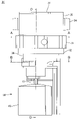
- FIG. 1 is a plan view of an assembled battery 10 used in an electric vehicle such as an electric forklift.
- the assembled battery 10 is composed of 12 lead-acid batteries 11 arranged in 6 horizontal rows and 2 vertical rows inside the battery case 13 .
- a lead-acid battery water faucet (hereinafter also simply referred to as a 'supplementary water faucet') 20 shown in FIG.
- Water taps 20 of adjacent lead-acid batteries 11 are connected via water supply tubes 12 .
- a water tank (not shown) to one end 12a of the water supply tube 12 and pumping water (an example of a "replenisher"), the 12 lead-acid batteries 11 can be supplied with water at once.
- the supplementary water tap 20 will be described below with reference to FIGS. 2 to 11.
- FIG. The supplementary water tap 20 includes a tap main body 30 and a float valve 60. - ⁇
- FIG. 2 is a perspective view of the replenishment tap 20, and FIG. 3 is a front view.
- the plug body 30 is made of synthetic resin such as ABS, and has a substantially cylindrical shape extending in the axial direction. 2 and 3 show a state in which the axial direction of the plug body 30 is oriented vertically.
- a brim portion 31 is the thickest portion in the horizontal direction of the plug body 30 .
- a ring-shaped rubber packing 32 is arranged along the outer circumference of the plug body 30 below the collar portion 31 .
- the rubber packing 32 is in tight contact with both the lower surface of the collar portion 31 and the upper surface of the battery lid to seal around the liquid port.
- the portion of the water replenishing tap 20 closer to the plug lid portion 37 than the rubber packing 32 is exposed above the upper surface of the battery lid, and the other portion is inserted into the liquid port of the battery lid and positioned inside the battery case. .
- a water supply port 33 (see FIG. 8) is provided on the upper surface of the flange portion 31, and a three-pronged water supply pipe joint 34 is connected to the water supply port 33.
- the water supply tubes 12 connected to the water supply pipe joints 34 connect the water supply pipe joints 34 of the adjacent lead-acid batteries 11 to each other.
- a semi-cylindrical portion 35 is erected on the upper surface of the brim portion 31 at a position on the front left side in FIG.
- the upper end of the semi-cylindrical portion 35 forms an opening 35a having a semi-circular opening edge.
- a plug lid portion 37 is connected via a hinge 36 to the chord portion of the opening edge.
- the opening 35a can be opened or closed by rotating the stopper 37 about the hinge 36. As shown in FIG.
- the plug body 30 has three partition walls (first partition wall 41 to third partition wall 43).
- the three partition walls 41-43 are integral with the plug body 30.
- the first partition wall 41 extends substantially parallel to the vertical direction inside the plug body 30 .
- both ends of the first partition 41 are connected to the peripheral wall 38, respectively, and the first partition 41 partitions the internal space of the plug body 30 into two spaces.
- the second partition 42 and the third partition 43 are partitions extending substantially parallel to the vertical direction inside the plug body 30 .
- the second partition 42 and the third partition 43 are arranged in each of the two internal spaces of the plug body 30 partitioned by the first partition 41 .
- the second partition 42 and the third partition 43 extend from the peripheral wall 38 toward the first partition 41 and are connected to the first partition 41 .
- the second partition 42 and the third partition 43 further partition the internal space of the plug body 30 divided into two by the first partition.
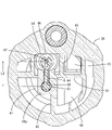
- FIG. 6 is a diagram schematically showing the positions of the first partition wall 41 to the third partition wall 43 superimposed on the plan view of the plug body 30.
- the internal space of the replenishment tap 20 partitioned into four by the first partition 41 to the third partition 43 is arranged counterclockwise from the lower right in FIGS. (2) front chamber 45, (3) water stop chamber 46, and (4) refilling chamber 47.
- the space on the side where the front chamber 45 and the water stop chamber 46 are provided is the “second 1 space”
- the space on the side where the refilling chamber 47 and the measurement chamber 44 are provided is the “second space”.
- each of the partitions 41-43 has a gap or a slit, and has a structure in which water can pass through the four divided spaces 44-47.
- the water in the front chamber 45 can flow into the water stop chamber 46 through a gap 52 formed below the end 49a of the first partition 41 (partition wall 49). It has become.
- a slit 39 extending over the water stop chamber 46 and the water replenishing chamber 47 is provided through the first partition wall 41 .
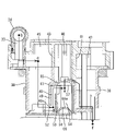
- FIG. 7 is a cross-sectional view along line CC in FIG. Points b to f in FIG. 7 respectively correspond to the positions of points b to f in FIG. 6 on the plan view. Arrows connecting the points in FIGS. 6 and 7 indicate the path of water inside the water retaining valve. The spaces 44 to 47 and the paths of water will be described below.
- the water supplied from the water supply tube 12 to the water supply port 33 passes through the water path inside the water replenishing valve, reaches the replenishing water chamber 47, and finally refills the battery tank.
- the water supply port 33 side is defined as the upstream side
- the water replenishing chamber 47 side is defined as the downstream side with reference to an arbitrary point in the water path.
- the measurement chamber 44 is a space surrounded by the peripheral wall 38, the first partition 41 and the second partition 42, and is located on the lower right in FIGS.
- the measurement chamber 44 does not have a ceiling surface and a bottom surface, and penetrates the supplementary water faucet 20 in the vertical direction.
- a portion of the measurement chamber 44 closer to the stopper lid portion 37 than the collar portion 31 is part of the internal space of the semi-cylindrical portion 35 .
- the measurement chamber 44 functions as an insertion port into which a specific gravity meter is inserted when measuring the specific gravity of the electrolyte. When a rod-shaped specific gravity meter is inserted into the specific gravity measurement port through the opening 35a of the semi-cylindrical portion 35, the tip of the specific gravity meter reaches the electrolyte, and the specific gravity can be measured.
- the front chamber 45 is a space surrounded by the peripheral wall 38, the first partition 41 and the third partition 43, and is located on the upper right in FIGS.
- the front chamber 45 communicates with the water supply port 33, and the water supplied to the water supply port 33 flows into and temporarily stays therein. Specifically, as shown in FIGS. 6 and 7, water supplied from the water supply tube 12 (point a) passes through the water supply pipe joint 34 (point b) and flows into the front chamber 45 from the water supply port 33. (point c).
- a guide passage 48 is provided at the boundary between the front chamber 45 and the water stop chamber 46, as shown in FIG.
- the guide passage 48 is formed by a partition wall 49 (part of the third partition wall 43) and a side wall 50 of the valve chamber 54.
- Water entering the guide passage 48 from the inlet (point d) flows through the guide passage 48 toward the downstream side, and then passes through an inlet 53 penetrating the upper portion of the side wall 50 of the valve chamber 54 and into the valve chamber 54 . (point e).
- the guide passage 48 is parallel to the moving direction (vertical direction) of the valve body 66 , and water moves through the guide passage 48 from bottom to top and reaches the inlet 53 .
- the guide passage 48 is an introduction portion that introduces water into the introduction port 53 .
- the water stop chamber 46 is a space surrounded by the peripheral wall 38, the first partition 41 and the third partition 43, and is located on the upper left in FIGS.
- the water stop chamber 46 has the guide passage 48 and the valve chamber 54 described above.
- valve chamber 54 is surrounded by a cylindrical side wall 50 whose axis extends in the vertical direction, a ceiling wall 57 and a bottom wall 51 .
- the valve chamber 54 accommodates a valve body 66 which will be described later.
- the valve chamber 54 has an inlet 53 and a discharge hole 55 on one wall surface of the valve chamber 54 .
- the introduction port 53 and the discharge hole 55 are provided through the side wall 50 and the ceiling wall 57, respectively.
- the water that has flowed into the valve chamber 54 from the inlet 53 is discharged from the discharge hole 55 into the space above the valve chamber 54 .
- the water replenishment chamber 47 is a space surrounded by the peripheral wall 38, the first partition 41 and the second partition 42, and is located at the lower left in FIGS. 4 to 6. As shown in FIG. 7, the refilling chamber 47 is open downward.
- the side of the replenishing water chamber 47 on the stopper lid portion 37 side is also the internal space of the semi-cylindrical portion 35 .
- the water flowing out from the discharge hole 55 into the upper space of the valve chamber 54 flows horizontally over the valve chamber 54, enters the replenishing water chamber 47, drops downward, and is replenished into the container (point f).
- FIG. 8 and 9 are DD cross-sectional views of the supplementary water tap 20.
- FIG. The refilling chamber 47 is provided with a pair of guide portions 56 that are vertically spaced apart from each other.
- Each of the pair of guide portions 56 is provided with an insertion hole penetrating in the vertical direction, and a float shaft 61 to be described later is inserted through the insertion hole.
- the float shaft 61 is vertically displaced while being kept substantially vertical by the pair of guide portions 56 .
- FIG. 10 shows an overall view of the float valve 60 .
- the float valve 60 is formed by connecting a float shaft 61, a water stop valve 62 and a float 63 integrally. A portion of the float valve 60 other than the float 63 is housed inside the plug body 30 (see FIG. 2). The float valve 60 is not fixed to the plug body 30 and can move up and down with respect to the plug body 30 .
- the float shaft 61 is supported in the refilling chamber 47 by a pair of guide portions 56 with its axis directed vertically.
- the float shaft 61 extends downward through the second guide portion 56b and protrudes downward from the bottom wall 51 of the plug body 30. As shown in FIG. 8,
- the float shaft 61 has a support portion 64 on its outer peripheral surface.
- the support portion 64 horizontally protrudes from the float shaft 61 between the first guide portion 56a and the second guide portion 56b.
- the support portion 64 penetrates through a slit 39 provided through the first partition wall 41 forming a boundary between the refilling chamber 47 and the water stop chamber 46 .
- the slit 39 is elongated in the vertical direction and functions as a guide groove that guides the vertical movement of the support portion 64 .
- the tip of the support portion 64 extends to the upper space of the valve chamber 54 and supports the water stop valve 62 housed in the valve chamber 54 in a suspended manner.
- the water stop valve 62 consists of a valve shaft 65 and a valve body 66 .
- the valve shaft 65 extends vertically and vertically penetrates the discharge hole 55 .
- the upper end of the valve shaft 65 is fixed to the support portion 64, and the valve body 66 is fixed to the lower end.
- the valve body 66 is accommodated in the valve chamber 54 so as to be vertically movable.
- the valve body 66 is positioned vertically facing each other with respect to the discharge hole 55 .
- the valve body 66 has a hemispherical shape that protrudes toward the discharge hole 55, and the upper surface 66a that contacts the discharge hole 55 is spherical.
- the float 63 is a substantially cylindrical floating body made of hollow or foamed synthetic resin.
- the lower end of the float shaft 61 is inserted into and fixed to the float 63 .
- the float 63 floats on the liquid surface of the electrolytic solution in the container and moves up and down following the liquid surface.
- the buoyancy of the float 63 causes the entire float valve 60 to follow the height of the liquid level and move up and down integrally.
- the range in which the float valve 60 moves up and down is between the lower limit position (Fig. 8) and the upper limit position (Fig. 9).
- the lower limit position is an example of a "first position”
- the upper limit position is an example of a "second position”.
- the water stop valve 62 at the lower limit position is separated from the discharge hole 55 and is in contact with the bottom wall 51, and the discharge hole 55 is open at this time (Fig. 8).
- the refilling tap 20 automatically stops refilling water when the liquid level reaches a predetermined height.
- FIG. 11 is a cross-sectional view (an enlarged view of the vicinity of the valve chamber 54 in FIG. 7) taken along the central axis L of the valve chamber 54 passing through the discharge hole 55.
- the discharge hole 55 vertically penetrates the ceiling wall 57 .
- the inner peripheral portion 55A of the discharge hole 55 has a conical shape, and the cross section has a tapered shape in which the opening area decreases from the inside to the outside of the valve chamber 54 (from the bottom to the top in FIG. 11).
- the introduction port 53 penetrates the side wall 50 in the horizontal direction and communicates the guide passage 48 with the valve chamber 54 .
- the range of the introduction port 53 is indicated by the A dimension.
- the introduction port 53 is positioned on an extension line of the tapered shape of the discharge hole 55 .
- a dashed line 58 in FIG. 11 is an extension of the tapered shape.
- the water flow R from the valve chamber 54 toward the discharge hole 55 flows into the discharge hole 55 along the tapered shape of the discharge hole 55. Since the introduction port 53 is positioned on the extension line 58 of the tapered shape, it can smoothly merge with the water flow R1 flowing into the discharge hole 55 along the tapered shape. As a result, turbulence is suppressed at the position where the water flow R and the water flow Q join, so that the influence of the turbulence on the opening/closing operation of the valve body 66 can be reduced.
- valve chamber 54 pressure loss in the valve chamber 54 is reduced by suppressing turbulence.
- pressure loss is small, the flow rate of water passing through the valve chamber 54 is less likely to decrease, so water can be replenished up to the specified amount in a short period of time.
- the valve chamber 54 has a configuration in which two members, an upper member 71 including a ceiling wall 57 and a lower member 72 including a bottom wall 51 are combined.
- the upper member 71 has a third partition wall 43 hanging down from above, a ceiling wall 57 extending horizontally from the third partition wall 43, and a partition wall 49 hanging down from the ceiling wall 57 and a first side wall 50a.
- the lower member 72 has a horizontally extending bottom wall 51 and a second side wall 50 b vertically rising from the bottom wall 51 .
- the first side wall 50a and the second side wall 50b are both curved in an arc shape in a plan view to form a cylindrical side wall 50 surrounding the valve body 66. As shown in FIG.
- the upper end of the second side wall 50b is cut into a horizontally long rectangular shape.
- the upper end of the second side wall and the ceiling wall are in contact with each other without gaps except for the notched portion, but the notched portion forms a rectangular opening.
- This opening is the introduction port 53 and communicates the valve chamber 54 and the guide passage 48 .
- the valve body 66 is lowered to the bottom wall 51 of the valve chamber 54 at the lower limit position (first position).
- the introduction port 53 is located above the valve body 66 at the lower limit position. Specifically, the lower end 53a of the introduction port 53 is above the upper surface 66a of the valve body 66, and the introduction port 53 does not overlap the valve body 66 at the lower limit position in the vertical direction. Further, as shown in FIG. 11, the introduction port 53 is positioned closer to the discharge hole 55 in the vertical direction than the valve body 66 at the lower limit position.
- the introduction port 55 By disposing the introduction port 55 closer to the discharge hole 55 than the valve body 66 at the lower limit position, the water flow (water flow Q) from the introduction port 53 toward the discharge hole 55 of the valve chamber 54 is reduced to the lower limit position. can merge with the water flow R near the discharge hole 55 without colliding with the valve body 66 at the bottom (non-interference). Therefore, turbulence can be suppressed near the inlet of the discharge hole. This makes it possible to create a smooth water flow from the inlet 53 to the outlet 55 .
- valve body 66 at the lower limit position and the water flow Q do not interfere with each other, it is possible to suppress the water flow Q from pushing the valve body 66 from the lower limit position toward the upper limit position. As a result, premature closing of the valve body 66 can be made difficult to occur.
- the valve body 66 is circular in plan view, and the side wall 50 is cylindrical surrounding the valve body 66 .
- the gap between the valve body 66 and the side wall 50 can be reduced. This makes it difficult for the water flow to flow to the opposite side of the valve body 66 , and prevents the water flow from interfering with the opening/closing operation of the valve body 66 .
- the valve body 66 vertically faces the discharge hole 55 in the valve chamber 54 .
- the valve body 66 has a hemispherical shape convex toward the discharge hole 55.
- the discharge hole 55 is positioned above and the valve body 66 is positioned below.
- valve body 66 has an upwardly convex hemispherical shape, even if a downward water stream hits the upper surface 66a, the force of the water stream can be parried along the spherical surface. Action can be performed.
- the assembled battery 10 used for an electric forklift is exemplified.
- the assembled battery 10 can also be used for an electric trolley, an aerial work vehicle, and the like.
- the application of the assembled battery 10 is not limited to a mobile object such as an electric vehicle. It can also be used for stationary applications such as uninterruptible power supplies and power storage devices for power generation systems.
- the introduction port 53 is provided at a position closer to the upper end of the side wall 50 (50b).
- the introduction port 53 may be a part of the introduction port 53 or may be on the extension line of the tapered shape of the discharge hole 55, for example, it may be located below the position in the above embodiment.
Abstract
This water-refilling faucet 20 for a lead storage battery is provided with: a faucet body 30; a valve chamber 54 that is positioned inside the faucet body 30 and that has an introduction port 53 and a discharge hole 55 for a refill liquid; and a valve body 66 accommodated in the valve chamber 54, the valve body 66 opening and closing the discharge hole 55. An inner circumferential portion 55A of the discharge hole 55 has a tapered shape in which the opening area decreases from the inside of the valve chamber 54 toward the outside thereof in a cross-section taken along a central axis L of the valve chamber 54 that passes through the discharge hole 55, and the introduction port 53 is positioned, relative to the discharge hole 55, on an extension line of the tapered shape of the inner circumferential portion of the discharge hole.
Description
本発明は、鉛蓄電池の電槽に補水を行う技術に関する。
The present invention relates to a technique for replenishing water in the container of a lead-acid battery.
鉛蓄電池は、使用中の電解反応や蒸発等により、電解液中の水分が減少して電解液の液面が次第に低下する。電解液の液面高さが一定の限度を下回らないように、電槽内に補水する必要がある。
In a lead-acid battery, due to electrolytic reaction and evaporation during use, the water content in the electrolyte decreases and the liquid level of the electrolyte gradually decreases. It is necessary to add water to the container so that the liquid level of the electrolyte does not fall below a certain limit.
特許文献1には、自動止水機能を有する蓄電池用補水栓が記載されている。特許文献1の蓄電池用補水栓は、電解液の液面に追従して上下動するフロートと、フロートに接続される皿状弁(弁体)と、弁体を収容する弁室と、を有している。弁室は、上流側の開口として流入口(導入口)を有し、下流側の開口として補水口(排出口)を有している。
Patent Document 1 describes a water faucet for a storage battery that has an automatic water stop function. The water supply valve for a storage battery of Patent Document 1 has a float that moves up and down following the liquid surface of the electrolyte, a disc-shaped valve (valve element) connected to the float, and a valve chamber that houses the valve element. doing. The valve chest has an inflow port (introduction port) as an upstream opening, and a refilling water port (outlet) as a downstream opening.
導入口から弁室に流入した水は、排出口から流出して、電槽へ補水される。電槽の液面が既定の高さまで上昇すると、フロートに接続されている弁体が排出口を閉止して止水し、補水は停止される。
The water that flows into the valve chamber from the inlet flows out from the outlet and replenishes the battery tank. When the liquid level in the container rises to a predetermined height, the valve body connected to the float closes the discharge port to stop the water supply, and refilling of water is stopped.
このような補水栓では、弁室の内部において乱流が発生することがある。乱流は弁体の開閉動作に影響を及ぼし、補水が不十分なのに排出口が閉止される「早閉まり」や、既に十分に補水されたのに排出口が閉止されない「遅閉まり」の原因となる。また、乱流が発生すると圧力損失により水圧が低下するため、流量が減少して電槽への補水に時間がかかってしまう。
In such a supplementary water tap, turbulence may occur inside the valve chamber. Turbulent flow affects the opening and closing action of the valve body, causing "early closing" in which the outlet closes even though water is not sufficiently replenished, and "late closing" in which the outlet does not close even though water has already been sufficiently replenished. Become. In addition, when turbulence occurs, the water pressure drops due to pressure loss, so the flow rate decreases and it takes time to replenish the water tank.
本発明は上記のような課題に基づいて完成されたものであって、弁室内における乱流の発生を抑制する技術を開示する。
The present invention has been completed based on the above problems, and discloses a technique for suppressing the occurrence of turbulence in the valve chamber.
鉛蓄電池用補水栓は、栓本体と、前記栓本体の内部に位置し、補充液の導入口と排出孔とを有する弁室と、前記弁室に収容され、前記排出孔の開放及び閉止を行う弁体と、を備え、前記排出孔の内周部は、前記排出孔を通る前記弁室の中心軸で切断した断面において、前記弁室の内から外に向かうにつれて開口面積が小さくなるテーパー形状であり、前記導入口は、前記排出孔との関係において、前記排出孔の内周部のテーパー形状の延長線上に位置する。
A lead-acid battery water replenishment valve comprises a plug body, a valve chamber located inside the plug body and having a replenisher inlet and a discharge hole, and a valve chamber accommodated in the valve chamber for opening and closing the discharge hole. and the inner peripheral portion of the discharge hole is tapered such that the opening area decreases from the inside to the outside of the valve chamber in a cross section cut along the central axis of the valve chamber passing through the discharge hole. and the introduction port is positioned on an extension of the tapered shape of the inner periphery of the discharge hole in relation to the discharge hole.
ここで、「導入口は、排出孔内周部のテーパー形状の延長線上に位置する」とは、導入口の一部でも、テーパー形状の延長線上に位置していることをいう。
Here, "the introduction port is located on the extension line of the tapered shape of the inner periphery of the discharge hole" means that even a part of the introduction port is located on the extension line of the tapered shape.
本発明によれば、弁室内における水の流れをスムーズにして乱流の発生を抑制し、弁体の開閉動作を円滑にするとともに、流量の低下を抑制できる。
According to the present invention, it is possible to suppress the occurrence of turbulence by smoothing the flow of water in the valve chamber, smoothen the opening and closing operation of the valve body, and suppress the decrease in the flow rate.
<鉛蓄電池用補水栓の概要>
(1)本発明の一実施形態に係る鉛蓄電池用補水栓は、栓本体と、前記栓本体の内部に位置し、補充液の導入口と排出孔とを有する弁室と、前記弁室に収容され、前記排出孔の開放及び閉止を行う弁体と、を備え、前記排出孔の内周部は、前記排出孔を通る前記弁室の中心軸で切断した断面において、前記弁室の内から外に向かうにつれて開口面積が小さくなるテーパー形状であり、前記導入口は、前記排出孔との関係において、前記排出孔の内周部のテーパー形状の延長線上に位置する。 <Overview of water tap for lead-acid battery>
(1) A supplementary water tap for a lead-acid battery according to an embodiment of the present invention includes a plug body, a valve chamber located inside the plug body and having an inlet and a discharge hole for a replenisher, and a valve body housed therein for opening and closing the discharge hole, wherein the inner peripheral portion of the discharge hole is the inner circumference of the valve chamber in a cross section cut along the central axis of the valve chamber passing through the discharge hole. The inlet has a tapered shape in which the opening area becomes smaller toward the outside, and the introduction port is positioned on an extension of the tapered shape of the inner peripheral portion of the discharge hole in relation to the discharge hole.
排出孔の内周部はテーパー形状であることから、排出孔付近では、テーパー形状に沿って、排出孔に流れ込む水流ができる。この構成では、導入口が、排出孔のテーパー形状の延長線上に位置するため、導入口から補充される補充液は、弁室内に流れ出た後、テーパー形状に沿って排出孔に流れ込む水流に合流する。そのため、弁室内において、排出孔に向かうスムーズな水流を作り、乱流の発生を抑制することができる。
Since the inner periphery of the discharge hole has a tapered shape, a water flow flows into the discharge hole along the tapered shape in the vicinity of the discharge hole. In this configuration, since the inlet is positioned on the extension of the tapered shape of the discharge hole, the replenisher supplied from the inlet flows out into the valve chamber and then joins the water stream flowing into the discharge hole along the tapered shape. do. Therefore, it is possible to create a smooth water flow toward the discharge hole in the valve chamber, thereby suppressing the occurrence of turbulence.
以上のことから、弁体の開閉動作に対する乱流の影響を抑え、弁体の開閉動作を円滑に行うことができる。また、乱流の発生を抑制すると、弁室を通過する補充液の圧力損失が低減する。これにより、補充液の圧力を維持して、弁室を通過する補充液の流量の低下を抑制できる。
From the above, the effect of turbulence on the opening and closing operation of the valve body can be suppressed, and the opening and closing operation of the valve body can be performed smoothly. Also, suppressing the occurrence of turbulence reduces the pressure loss of the replenisher passing through the valve chamber. As a result, the pressure of the replenisher can be maintained, and the decrease in the flow rate of the replenisher passing through the valve chamber can be suppressed.
(2)上記(1)に記載の鉛蓄電池用補水栓において、前記弁体は、前記排出孔から離隔して開放する第1位置と、前記排出孔に当接して閉止する第2位置との間で移動し、前記導入口は、前記弁体との関係において、前記第1位置にある前記弁体よりも前記排出孔に近い位置にあってもよい。
(2) In the lead-acid battery water supply faucet according to (1) above, the valve body has a first position in which it is separated from the discharge hole and opened, and a second position in which it contacts and closes the discharge hole. and the inlet may be in a position relative to the valve body that is closer to the outlet hole than the valve body is in the first position.
このような構成では、導入口から流入する補充液の水流が、第1位置にある弁体に対して非干渉であることから、水流が弁体にぶつからず、乱流が発生しにくい。これにより、排出孔に向かうスムーズな水流を作ることができる。また、水流が弁体を第1位置から第2位置へと押し込むことを抑制でき、早閉まりが起こりにくい。
With such a configuration, the water flow of the replenisher flowing in from the inlet does not interfere with the valve body in the first position, so the water flow does not collide with the valve body and turbulence is less likely to occur. This creates a smooth water flow towards the discharge hole. In addition, it is possible to suppress the water flow from pushing the valve body from the first position to the second position, which makes it difficult for the valve to close prematurely.
(3)上記(1)又は(2)に記載の鉛蓄電池用補水栓において、前記排出孔は、前記弁室の一壁面を貫通しており、前記弁体は、前記弁室内において前記排出孔と向かい合って位置し、前記排出孔に向かって凸の半球状であってもよい。
(3) In the lead-acid battery water supply valve according to (1) or (2) above, the discharge hole penetrates through one wall surface of the valve chamber, and the valve body is disposed in the valve chamber with the discharge hole facing each other and having a hemispherical shape convex toward the discharge hole.
このようにすると、補充液に含まれる固形の異物が、弁体の上面に乗り上げても、球面に沿って滑り、落ちやすい。弁体の上面に異物が残存しにくいため、弁体と排出孔との間に異物が挟まって閉止時の排出孔から補充液が漏れだすことを抑制できる。
By doing so, even if solid foreign matter contained in the replenisher runs on the upper surface of the valve body, it slides along the spherical surface and falls easily. Since foreign matter does not easily remain on the upper surface of the valve body, it is possible to prevent foreign matter from being caught between the valve body and the discharge hole, thereby preventing leakage of the replenisher from the discharge hole when the valve is closed.
また、排出孔に向かう補充液が排出孔を通過できずに下方の弁体へ向かって流れると、水流が弁体を押して開閉動作を妨げるおそれがある。弁体が上に凸の半球状だと、上方から補充液の水流が当たっても、球面に沿って勢いを受け流すことができ、開閉動作の妨げになりにくい。
Also, if the replenisher flowing toward the discharge hole cannot pass through the discharge hole and flows toward the lower valve body, the water flow may push the valve body and hinder the opening and closing operation. If the valve body has a hemispherical shape with an upward projection, even if the water flow of the replenisher hits it from above, the momentum can be deflected along the spherical surface, and the opening and closing operation is less likely to be hindered.
(4)上記(1)から(3)のいずれか一項に記載の鉛蓄電池用補水栓において、補充液を前記導入口に導く導入部を有してもよい。前記導入部は、前記弁体の移動方向と平行でもよい。導入部が弁体の移動方向と直交する場合に比べ、導入口から弁室に流れ込む補充液の水流が弁体の移動の妨げになることが少ない。そのため、弁体の移動が滑らかになり、良好な止水性を確保できる。
(4) The lead-acid battery water faucet according to any one of (1) to (3) above may have an introducing portion that guides a replenisher to the inlet. The introduction portion may be parallel to the movement direction of the valve body. Compared to the case where the introduction portion is perpendicular to the moving direction of the valve body, the water flow of the replenisher flowing into the valve chamber from the introduction port does not hinder the movement of the valve body. Therefore, the movement of the valve body becomes smooth, and a good water cutoff property can be ensured.
(5)本技術の対象は、上記(1)から(4)のいずれか一項の鉛蓄電池用補水栓を備えた鉛蓄電池でもよい。
(5) The target of the present technology may be a lead-acid battery equipped with a lead-acid battery water faucet according to any one of (1) to (4) above.
(6)上記(5)に記載の鉛蓄電池を複数備える組電池であって、一の前記鉛蓄電池が有する鉛蓄電池用補水栓は、他の前記鉛蓄電池が有する鉛蓄電池用補水栓と、給水チューブを介して接続されていてもよい。
(6) In an assembled battery including a plurality of lead-acid batteries according to (5) above, the lead-acid battery water tap of one of the lead-acid batteries includes a lead-acid battery water tap of the other lead-acid battery and a water supply. It may be connected via a tube.
給水チューブの一端から補充液を補充すると、各鉛蓄電池に対し、所定値まで補充液を供給することができる。複数の鉛蓄電池に対して一括して補充液の補充ができる。
By replenishing the replenisher from one end of the water supply tube, the replenisher can be supplied to each lead-acid battery up to a predetermined value. The replenisher can be replenished collectively for multiple lead-acid batteries.
<実施形態>
1.全体構成
図1は、電動フォークリフト等の電気車両に用いられる組電池10の平面図である。組電池10は、12個の鉛蓄電池11からなり、電池ケース13の内部において、横6列、縦2列に配置されている。 <Embodiment>
1. Overall Configuration FIG. 1 is a plan view of an assembledbattery 10 used in an electric vehicle such as an electric forklift. The assembled battery 10 is composed of 12 lead-acid batteries 11 arranged in 6 horizontal rows and 2 vertical rows inside the battery case 13 .
1.全体構成
図1は、電動フォークリフト等の電気車両に用いられる組電池10の平面図である。組電池10は、12個の鉛蓄電池11からなり、電池ケース13の内部において、横6列、縦2列に配置されている。 <Embodiment>
1. Overall Configuration FIG. 1 is a plan view of an assembled
鉛蓄電池11の電池蓋上面に貫設された液口に、図2に示す鉛蓄電池用補水栓(以下、単に「補水栓」ともいう)20が取り付けられる。隣接する鉛蓄電池11の補水栓20同士は、給水チューブ12を介して接続される。給水チューブ12の一端12aに水タンク(図示しない)を接続して水(「補充液」の一例)を圧送すると、12個の鉛蓄電池11に一括して給水できるようになっている。
A lead-acid battery water faucet (hereinafter also simply referred to as a 'supplementary water faucet') 20 shown in FIG. Water taps 20 of adjacent lead-acid batteries 11 are connected via water supply tubes 12 . By connecting a water tank (not shown) to one end 12a of the water supply tube 12 and pumping water (an example of a "replenisher"), the 12 lead-acid batteries 11 can be supplied with water at once.
以下、図2から図11を用いて補水栓20について説明する。補水栓20は、栓本体30と、フロート弁60と、を備えている。
The supplementary water tap 20 will be described below with reference to FIGS. 2 to 11. FIG. The supplementary water tap 20 includes a tap main body 30 and a float valve 60. - 特許庁
2.栓本体
図2は補水栓20の斜視図、図3は正面図である。栓本体30はABS等の合成樹脂製であり、軸方向に延びる略筒型である。図2、図3は、栓本体30の軸方向を上下方向に向けた状態を示している。栓本体30のうち、水平方向に最も太くなっている部分が鍔部31である。鍔部31の下方には、リング状のゴムパッキン32が栓本体30の外周に沿って配されている。補水栓20を鉛蓄電池11に取り付けた状態では、ゴムパッキン32は、鍔部31の下面と電池蓋の上面の双方に隙間なく密着して、液口周りをシールする。この状態では、補水栓20のゴムパッキン32よりも栓蓋部37側の部分は電池蓋上面より上に露出し、他の部分は電池蓋の液口に差し込まれて電槽の内部に位置する。 2. Plug Main Body FIG. 2 is a perspective view of thereplenishment tap 20, and FIG. 3 is a front view. The plug body 30 is made of synthetic resin such as ABS, and has a substantially cylindrical shape extending in the axial direction. 2 and 3 show a state in which the axial direction of the plug body 30 is oriented vertically. A brim portion 31 is the thickest portion in the horizontal direction of the plug body 30 . A ring-shaped rubber packing 32 is arranged along the outer circumference of the plug body 30 below the collar portion 31 . When the supplementary water tap 20 is attached to the lead-acid battery 11, the rubber packing 32 is in tight contact with both the lower surface of the collar portion 31 and the upper surface of the battery lid to seal around the liquid port. In this state, the portion of the water replenishing tap 20 closer to the plug lid portion 37 than the rubber packing 32 is exposed above the upper surface of the battery lid, and the other portion is inserted into the liquid port of the battery lid and positioned inside the battery case. .
図2は補水栓20の斜視図、図3は正面図である。栓本体30はABS等の合成樹脂製であり、軸方向に延びる略筒型である。図2、図3は、栓本体30の軸方向を上下方向に向けた状態を示している。栓本体30のうち、水平方向に最も太くなっている部分が鍔部31である。鍔部31の下方には、リング状のゴムパッキン32が栓本体30の外周に沿って配されている。補水栓20を鉛蓄電池11に取り付けた状態では、ゴムパッキン32は、鍔部31の下面と電池蓋の上面の双方に隙間なく密着して、液口周りをシールする。この状態では、補水栓20のゴムパッキン32よりも栓蓋部37側の部分は電池蓋上面より上に露出し、他の部分は電池蓋の液口に差し込まれて電槽の内部に位置する。 2. Plug Main Body FIG. 2 is a perspective view of the
鍔部31の上面には、給水口33(図8参照)が設けられており、給水口33に対して三叉状の給水管継手34が接続されている。給水管継手34に接続される給水チューブ12は、隣接する鉛蓄電池11の給水管継手34同士を接続する。
A water supply port 33 (see FIG. 8) is provided on the upper surface of the flange portion 31, and a three-pronged water supply pipe joint 34 is connected to the water supply port 33. The water supply tubes 12 connected to the water supply pipe joints 34 connect the water supply pipe joints 34 of the adjacent lead-acid batteries 11 to each other.
鍔部31の上面には、給水口33と平面視にて重複しない、図2の左手前側の位置に、半円筒部35が立設されている。半円筒部35の上端は、半円状の開口縁を有する開口35aとなっている。開口縁の弦の部分には、ヒンジ36を介して栓蓋部37が連結されている。ヒンジ36を軸にして栓蓋部37を回動させることで、開口35aを開放または閉止できる。
A semi-cylindrical portion 35 is erected on the upper surface of the brim portion 31 at a position on the front left side in FIG. The upper end of the semi-cylindrical portion 35 forms an opening 35a having a semi-circular opening edge. A plug lid portion 37 is connected via a hinge 36 to the chord portion of the opening edge. The opening 35a can be opened or closed by rotating the stopper 37 about the hinge 36. As shown in FIG.
図4、図5は、それぞれ図3に示す栓本体30のA-A、B-B断面図である。栓本体30は3つの隔壁(第1隔壁41~第3隔壁43)を有している。3つの隔壁41~43は、栓本体30と一体である。第1隔壁41は、栓本体30の内部において、上下方向に対して略平行に延在している。図5に示すように、第1隔壁41の両端は、それぞれ周壁38に接続されており、第1隔壁41は、栓本体30の内部空間を2つの空間に仕切っている。
4 and 5 are AA and BB cross-sectional views of the plug body 30 shown in FIG. 3, respectively. The plug body 30 has three partition walls (first partition wall 41 to third partition wall 43). The three partition walls 41-43 are integral with the plug body 30. As shown in FIG. The first partition wall 41 extends substantially parallel to the vertical direction inside the plug body 30 . As shown in FIG. 5, both ends of the first partition 41 are connected to the peripheral wall 38, respectively, and the first partition 41 partitions the internal space of the plug body 30 into two spaces.
第2隔壁42、第3隔壁43は、栓本体30の内部において上下方向に対して略平行に延在する隔壁である。第2隔壁42、第3隔壁43は、第1隔壁41によって2つに仕切られた栓本体30の内部空間のそれぞれに1つずつ配されている。第2隔壁42、第3隔壁43は、それぞれ周壁38から第1隔壁41に向かって延出し、第1隔壁41に対して接続されている。第2隔壁42、第3隔壁43は、第1隔壁が2つに仕切った栓本体30の内部空間のそれぞれを、さらに仕切っている。
The second partition 42 and the third partition 43 are partitions extending substantially parallel to the vertical direction inside the plug body 30 . The second partition 42 and the third partition 43 are arranged in each of the two internal spaces of the plug body 30 partitioned by the first partition 41 . The second partition 42 and the third partition 43 extend from the peripheral wall 38 toward the first partition 41 and are connected to the first partition 41 . The second partition 42 and the third partition 43 further partition the internal space of the plug body 30 divided into two by the first partition.
図6は、第1隔壁41~第3隔壁43の位置を、栓本体30の平面図に重ねて模式的に示した図である。以下の説明では、第1隔壁41~第3隔壁43によって4つに仕切られた補水栓20の内部空間を、図4~図6の右下から反時計回りに、(1)測定室44、(2)前室45、(3)止水室46、(4)補水室47とする。
FIG. 6 is a diagram schematically showing the positions of the first partition wall 41 to the third partition wall 43 superimposed on the plan view of the plug body 30. As shown in FIG. In the following description, the internal space of the replenishment tap 20 partitioned into four by the first partition 41 to the third partition 43 is arranged counterclockwise from the lower right in FIGS. (2) front chamber 45, (3) water stop chamber 46, and (4) refilling chamber 47.
第1隔壁41によって2つに仕切られた栓本体30の内部空間のうち、前室45と止水室46が設けられている側(弁室54が設けられている側)の空間が「第1空間」であり、補水室47と測定室44が設けられている側の空間(弁室54が設けられていない側の空間)が「第2空間」である。
Of the internal space of the plug body 30 divided into two by the first partition 41, the space on the side where the front chamber 45 and the water stop chamber 46 are provided (the side where the valve chamber 54 is provided) is the "second 1 space”, and the space on the side where the refilling chamber 47 and the measurement chamber 44 are provided (the space on the side where the valve chamber 54 is not provided) is the “second space”.
各隔壁41~43の一部には、隙間やスリットが設けられた部分があり、4つに分割された空間44~47を水が通過できる構造になっている。例えば、後述するが、図7に示すように、前室45内の水は第1隔壁41(仕切壁49)の端部49aの下方に開けられた隙間52を通じて止水室46へ流入できるようになっている。また、図4に示すように、第1隔壁41には止水室46と補水室47に跨るスリット39が貫設されている。
A part of each of the partitions 41-43 has a gap or a slit, and has a structure in which water can pass through the four divided spaces 44-47. For example, as will be described later, as shown in FIG. 7, the water in the front chamber 45 can flow into the water stop chamber 46 through a gap 52 formed below the end 49a of the first partition 41 (partition wall 49). It has become. Further, as shown in FIG. 4 , a slit 39 extending over the water stop chamber 46 and the water replenishing chamber 47 is provided through the first partition wall 41 .
図7は、図6のC-C線に沿った断面図である。図7中の点b~点fは、図6における点b~点fの平面図上の位置にそれぞれ対応している。各点を結ぶ図6、図7中の矢線は、保水栓の内部における水の経路を示している。以下、各空間44~47と水の経路について説明する。給水チューブ12から給水口33に供給された水は、補水栓内部の水の経路を通って補水室47に至り、最終的に電槽へと補水される。以降の説明では、水の経路における任意の箇所を基準として、給水口33側を上流側、補水室47側を下流側とする。
FIG. 7 is a cross-sectional view along line CC in FIG. Points b to f in FIG. 7 respectively correspond to the positions of points b to f in FIG. 6 on the plan view. Arrows connecting the points in FIGS. 6 and 7 indicate the path of water inside the water retaining valve. The spaces 44 to 47 and the paths of water will be described below. The water supplied from the water supply tube 12 to the water supply port 33 passes through the water path inside the water replenishing valve, reaches the replenishing water chamber 47, and finally refills the battery tank. In the following description, the water supply port 33 side is defined as the upstream side, and the water replenishing chamber 47 side is defined as the downstream side with reference to an arbitrary point in the water path.
(1)測定室44は、周壁38と、第1隔壁41及び第2隔壁42で囲まれた空間であり、図4~図6では右下に位置する。測定室44は天井面及び底面を有しておらず、補水栓20を上下方向に貫通している。測定室44の鍔部31よりも栓蓋部37側の部分は、半円筒部35の内部空間の一部である。測定室44は、電解液の比重を測定する際に比重計を差し込む差込口として機能する。半円筒部35の開口35aから棒状の比重計を比重測定口に差し込むと、比重計の先端は電解液に到達し、比重の測定ができるようになっている。
(1) The measurement chamber 44 is a space surrounded by the peripheral wall 38, the first partition 41 and the second partition 42, and is located on the lower right in FIGS. The measurement chamber 44 does not have a ceiling surface and a bottom surface, and penetrates the supplementary water faucet 20 in the vertical direction. A portion of the measurement chamber 44 closer to the stopper lid portion 37 than the collar portion 31 is part of the internal space of the semi-cylindrical portion 35 . The measurement chamber 44 functions as an insertion port into which a specific gravity meter is inserted when measuring the specific gravity of the electrolyte. When a rod-shaped specific gravity meter is inserted into the specific gravity measurement port through the opening 35a of the semi-cylindrical portion 35, the tip of the specific gravity meter reaches the electrolyte, and the specific gravity can be measured.
(2)前室45は、周壁38と、第1隔壁41及び第3隔壁43で囲まれた空間であり、図4~図6では右上に位置する。前室45は給水口33と連通しており、給水口33に供給された水が流入して一時的に滞留する。具体的には、図6、図7に示すように、給水チューブ12から供給された水は(点a)、給水管継手34を通り(点b)、給水口33から前室45に流入する(点c)。
(2) The front chamber 45 is a space surrounded by the peripheral wall 38, the first partition 41 and the third partition 43, and is located on the upper right in FIGS. The front chamber 45 communicates with the water supply port 33, and the water supplied to the water supply port 33 flows into and temporarily stays therein. Specifically, as shown in FIGS. 6 and 7, water supplied from the water supply tube 12 (point a) passes through the water supply pipe joint 34 (point b) and flows into the front chamber 45 from the water supply port 33. (point c).
前室45と止水室46との境界には、図7に示すように、案内通路48が設けられている。案内通路48は、仕切壁49(第3隔壁43の一部)と、弁室54の側壁50とによって形成されている。仕切壁49の端部49aと栓本体30の底壁51との間には隙間52があり、この隙間52が案内通路48の入口になっている。入口から案内通路48に入り込んだ水は(点d)、案内通路48を下流側に向かって流れ、その後、弁室54の側壁50の上部に貫設された導入口53を通って弁室54内に流入する(点e)。図11に示すように案内通路48は、弁体66の移動方向(上下方向)と平行であり、水は、案内通路48を下から上に移動して導入口53に至る。案内通路48は水を導入口53に導入する導入部である。
A guide passage 48 is provided at the boundary between the front chamber 45 and the water stop chamber 46, as shown in FIG. The guide passage 48 is formed by a partition wall 49 (part of the third partition wall 43) and a side wall 50 of the valve chamber 54. As shown in FIG. There is a gap 52 between the end 49a of the partition wall 49 and the bottom wall 51 of the plug body 30, and this gap 52 serves as the entrance of the guide passage 48. As shown in FIG. Water entering the guide passage 48 from the inlet (point d) flows through the guide passage 48 toward the downstream side, and then passes through an inlet 53 penetrating the upper portion of the side wall 50 of the valve chamber 54 and into the valve chamber 54 . (point e). As shown in FIG. 11 , the guide passage 48 is parallel to the moving direction (vertical direction) of the valve body 66 , and water moves through the guide passage 48 from bottom to top and reaches the inlet 53 . The guide passage 48 is an introduction portion that introduces water into the introduction port 53 .
(3)止水室46は、周壁38と、第1隔壁41及び第3隔壁43で囲まれた空間であり、図4~図6では左上に位置する。止水室46は、上述した案内通路48と、弁室54とを有している。
(3) The water stop chamber 46 is a space surrounded by the peripheral wall 38, the first partition 41 and the third partition 43, and is located on the upper left in FIGS. The water stop chamber 46 has the guide passage 48 and the valve chamber 54 described above.
図7に示すように、弁室54は、上下方向を軸とする円筒状の側壁50と、天井壁57と、底壁51に囲まれている。弁室54は、後述する弁体66を収容している。
As shown in FIG. 7, the valve chamber 54 is surrounded by a cylindrical side wall 50 whose axis extends in the vertical direction, a ceiling wall 57 and a bottom wall 51 . The valve chamber 54 accommodates a valve body 66 which will be described later.
弁室54は、弁室54の一壁面に、導入口53と排出孔55を有している。この例では、導入口53は側壁50に、排出孔55は天井壁57にそれぞれ貫設されている。導入口53から弁室54に流入した水は、排出孔55から弁室54の上方空間に排出される。
The valve chamber 54 has an inlet 53 and a discharge hole 55 on one wall surface of the valve chamber 54 . In this example, the introduction port 53 and the discharge hole 55 are provided through the side wall 50 and the ceiling wall 57, respectively. The water that has flowed into the valve chamber 54 from the inlet 53 is discharged from the discharge hole 55 into the space above the valve chamber 54 .
(4)補水室47は、周壁38と、第1隔壁41及び第2隔壁42で囲まれた空間であり、図4~図6では左下に位置する。図7に示すように、補水室47は下方に開口が開放されている。補水室47の栓蓋部37側は半円筒部35の内部空間でもある。排出孔55から弁室54の上方空間に流出した水は、弁室54の上を水平方向に流れて補水室47に入り、下方に落下して電槽内へ補充される(点f)。
(4) The water replenishment chamber 47 is a space surrounded by the peripheral wall 38, the first partition 41 and the second partition 42, and is located at the lower left in FIGS. 4 to 6. As shown in FIG. 7, the refilling chamber 47 is open downward. The side of the replenishing water chamber 47 on the stopper lid portion 37 side is also the internal space of the semi-cylindrical portion 35 . The water flowing out from the discharge hole 55 into the upper space of the valve chamber 54 flows horizontally over the valve chamber 54, enters the replenishing water chamber 47, drops downward, and is replenished into the container (point f).
図8及び図9は、補水栓20のD-D断面図である。補水室47には、上下方向に間隔を空けて並ぶ一対の案内部56が設けられている。一対の案内部56には、それぞれ上下方向に貫通する挿通孔が設けられており、挿通孔には後述するフロート軸61が挿通される。フロート軸61は、一対の案内部56により、略垂直に保たれたまま上下方向に変位する。
8 and 9 are DD cross-sectional views of the supplementary water tap 20. FIG. The refilling chamber 47 is provided with a pair of guide portions 56 that are vertically spaced apart from each other. Each of the pair of guide portions 56 is provided with an insertion hole penetrating in the vertical direction, and a float shaft 61 to be described later is inserted through the insertion hole. The float shaft 61 is vertically displaced while being kept substantially vertical by the pair of guide portions 56 .
3.フロート弁
図10に、フロート弁60の全体図を示す。フロート弁60は、フロート軸61、止水弁62及びフロート63が一体的に接続されてなる。フロート弁60の、フロート63を除く部分は、栓本体30の内部に収容されている(図2参照)。フロート弁60は、栓本体30に対して固定されておらず、栓本体30に対して上下動できる。 3. Float Valve FIG. 10 shows an overall view of thefloat valve 60 . The float valve 60 is formed by connecting a float shaft 61, a water stop valve 62 and a float 63 integrally. A portion of the float valve 60 other than the float 63 is housed inside the plug body 30 (see FIG. 2). The float valve 60 is not fixed to the plug body 30 and can move up and down with respect to the plug body 30 .
図10に、フロート弁60の全体図を示す。フロート弁60は、フロート軸61、止水弁62及びフロート63が一体的に接続されてなる。フロート弁60の、フロート63を除く部分は、栓本体30の内部に収容されている(図2参照)。フロート弁60は、栓本体30に対して固定されておらず、栓本体30に対して上下動できる。 3. Float Valve FIG. 10 shows an overall view of the
図8に示すように、フロート軸61は、補水室47内において、一対の案内部56により軸線を上下方向に向けた状態で支持されている。また、フロート軸61は、第2案内部56bを貫通して下方に延びており、栓本体30の底壁51から下方に突出している。
As shown in FIG. 8, the float shaft 61 is supported in the refilling chamber 47 by a pair of guide portions 56 with its axis directed vertically. The float shaft 61 extends downward through the second guide portion 56b and protrudes downward from the bottom wall 51 of the plug body 30. As shown in FIG.
フロート軸61は、外周面に支持部64を有している。支持部64は、第1案内部56aと第2案内部56bの間において、フロート軸61から水平方向に突出している。支持部64は、補水室47と止水室46との境界をなす第1隔壁41に貫設された、スリット39を貫通している。スリット39は上下方向に長い形状であり、支持部64の上下移動を案内するガイド溝としての機能を有している。支持部64の先端は、弁室54の上部空間まで延びており、弁室54に収容された止水弁62を吊り下げる形で支持している。
The float shaft 61 has a support portion 64 on its outer peripheral surface. The support portion 64 horizontally protrudes from the float shaft 61 between the first guide portion 56a and the second guide portion 56b. The support portion 64 penetrates through a slit 39 provided through the first partition wall 41 forming a boundary between the refilling chamber 47 and the water stop chamber 46 . The slit 39 is elongated in the vertical direction and functions as a guide groove that guides the vertical movement of the support portion 64 . The tip of the support portion 64 extends to the upper space of the valve chamber 54 and supports the water stop valve 62 housed in the valve chamber 54 in a suspended manner.
止水弁62は、弁軸65及び弁体66からなる。弁軸65は上下方向に延び、排出孔55を上下に貫通する。弁軸65の上端は支持部64に固定され、下端には弁体66が固定されている。
The water stop valve 62 consists of a valve shaft 65 and a valve body 66 . The valve shaft 65 extends vertically and vertically penetrates the discharge hole 55 . The upper end of the valve shaft 65 is fixed to the support portion 64, and the valve body 66 is fixed to the lower end.
弁体66は、弁室54内において、上下方向に移動可能な状態で収容されている。弁体66は、排出孔55との関係では、上下に向かい合って位置している。弁体66は、排出孔55に向かって凸の半球状であり、排出孔55と当接する上面66aは、球面である。
The valve body 66 is accommodated in the valve chamber 54 so as to be vertically movable. The valve body 66 is positioned vertically facing each other with respect to the discharge hole 55 . The valve body 66 has a hemispherical shape that protrudes toward the discharge hole 55, and the upper surface 66a that contacts the discharge hole 55 is spherical.
フロート63は、中空または発泡性の合成樹脂からなる略円柱状の浮体である。フロート63には、フロート軸61の下端が差し込まれて固定されている。フロート63は、電槽内において電解液の液面に浮かんでおり、液面に追従して上下動する。
The float 63 is a substantially cylindrical floating body made of hollow or foamed synthetic resin. The lower end of the float shaft 61 is inserted into and fixed to the float 63 . The float 63 floats on the liquid surface of the electrolytic solution in the container and moves up and down following the liquid surface.
電解液の増減に伴って液面が上下動すると、フロート63の浮力により、フロート弁60全体が液面の高さに追従して一体的に上下動する。
When the liquid level moves up and down as the electrolyte increases and decreases, the buoyancy of the float 63 causes the entire float valve 60 to follow the height of the liquid level and move up and down integrally.
フロート弁60が上下動する範囲は、下限位置(図8)と上限位置(図9)の間である。下限位置は「第1位置」の一例、上限位置は、「第2位置」の一例である。
The range in which the float valve 60 moves up and down is between the lower limit position (Fig. 8) and the upper limit position (Fig. 9). The lower limit position is an example of a "first position", and the upper limit position is an example of a "second position".
下限位置にあるときの止水弁62は、排出孔55から離隔して底壁51に当接しており、このとき排出孔55は開放されている(図8)。
The water stop valve 62 at the lower limit position is separated from the discharge hole 55 and is in contact with the bottom wall 51, and the discharge hole 55 is open at this time (Fig. 8).
フロート弁60が下限位置から上限位置に移動すると、弁体66が下方から排出孔55に当接して排出孔55を閉止する(図9)。
When the float valve 60 moves from the lower limit position to the upper limit position, the valve body 66 contacts the discharge hole 55 from below to close the discharge hole 55 (Fig. 9).
4.自動止水機能
次に、補水栓20の自動止水機能について説明する。電気分解や蒸発により電槽内の電解液が減少して液面が下降すると、電解液の液面に浮かぶフロート63も連動して下降し、やがてフロート弁60は下限位置に至る(図8)。 4. Automatic Water Stop Function Next, the automatic water stop function of thesupplementary water tap 20 will be described. When the electrolyte in the container decreases due to electrolysis or evaporation and the liquid level drops, the float 63 floating on the liquid level of the electrolyte also drops, and eventually the float valve 60 reaches the lower limit position (Fig. 8). .
次に、補水栓20の自動止水機能について説明する。電気分解や蒸発により電槽内の電解液が減少して液面が下降すると、電解液の液面に浮かぶフロート63も連動して下降し、やがてフロート弁60は下限位置に至る(図8)。 4. Automatic Water Stop Function Next, the automatic water stop function of the
給水口33に水を供給すると、図7の矢線で示す経路の通り、水は給水口33から順に、前室45、案内通路48、導入口53、弁室54、排出孔55、補水室47を経て、電槽内へ補充される。電槽に水が補充されると、電解液の液面は上昇し、これに連動してフロート弁60も上昇する。液面が所定の高さに達したときに、フロート弁60は上限位置に至り、弁室54内の弁体66が、フロート63の浮力により下方から排出孔55に押し付けられ、排出孔55が閉止される(図9)。
When water is supplied to the water supply port 33, as indicated by the arrows in FIG. 47, it is replenished into the container. When the container is replenished with water, the liquid level of the electrolyte rises, and the float valve 60 also rises accordingly. When the liquid level reaches a predetermined height, the float valve 60 reaches the upper limit position, and the valve body 66 in the valve chamber 54 is pressed against the discharge hole 55 from below by the buoyancy of the float 63, and the discharge hole 55 is closed. It is closed (Fig. 9).
排出孔55が閉止されると、弁室54内の水は排出孔55を通過できなくなり、電槽内への補水が停止する。このようにして、補水栓20では、液面の高さが所定の高さに達すると、補水は自動的に停止する。
When the discharge hole 55 is closed, the water in the valve chamber 54 cannot pass through the discharge hole 55, and refilling of water into the container is stopped. In this manner, the refilling tap 20 automatically stops refilling water when the liquid level reaches a predetermined height.
この自動補水機能により、各蓄電池に個々に補水作業を行うことなく、組電池10を構成する全ての鉛蓄電池11に対して、1つの水タンクから一括して補水することができる。
With this automatic water replenishment function, all the lead-acid batteries 11 that make up the assembled battery 10 can be replenished with water collectively from one water tank without individually refilling each storage battery.
5.弁室における水流の説明
図11は、排出孔55を通る弁室54の中心軸Lでの断面図(図7における弁室54周辺を拡大した図)である。排出孔55は、天井壁57を上下方向に貫通している。排出孔55の内周部55Aは、円錐状であり、上記断面では、弁室54の内から外(図11では下から上)に向かうにつれて開口面積が小さくなるテーパー形状である。 5. Explanation of Water Flow in Valve Chamber FIG. 11 is a cross-sectional view (an enlarged view of the vicinity of thevalve chamber 54 in FIG. 7) taken along the central axis L of the valve chamber 54 passing through the discharge hole 55. As shown in FIG. The discharge hole 55 vertically penetrates the ceiling wall 57 . The inner peripheral portion 55A of the discharge hole 55 has a conical shape, and the cross section has a tapered shape in which the opening area decreases from the inside to the outside of the valve chamber 54 (from the bottom to the top in FIG. 11).
図11は、排出孔55を通る弁室54の中心軸Lでの断面図(図7における弁室54周辺を拡大した図)である。排出孔55は、天井壁57を上下方向に貫通している。排出孔55の内周部55Aは、円錐状であり、上記断面では、弁室54の内から外(図11では下から上)に向かうにつれて開口面積が小さくなるテーパー形状である。 5. Explanation of Water Flow in Valve Chamber FIG. 11 is a cross-sectional view (an enlarged view of the vicinity of the
導入口53は、側壁50を水平方向に貫通し、案内通路48と弁室54を連通する。図11において、導入口53の範囲をA寸法で示している。また、導入口53は、排出孔55との関係では、排出孔55のテーパー形状の延長線上に位置する。図11の一点鎖線58は、テーパー形状の延長線である。
The introduction port 53 penetrates the side wall 50 in the horizontal direction and communicates the guide passage 48 with the valve chamber 54 . In FIG. 11, the range of the introduction port 53 is indicated by the A dimension. In relation to the discharge hole 55 , the introduction port 53 is positioned on an extension line of the tapered shape of the discharge hole 55 . A dashed line 58 in FIG. 11 is an extension of the tapered shape.
弁室54に水が供給されると、図11に示すように、案内通路48を経由して導入口53から弁室54に流入する水流Qと、弁室54から排出孔55を通り上方空間に向かう水流Rがそれぞれ発生する。
When water is supplied to the valve chamber 54, as shown in FIG. A water flow R directed toward is generated respectively.
排出孔55の内周部55Aはテーパー形状であるため、弁室54から排出孔55に向かう水流Rは、排出孔55のテーパー形状に沿って排出孔55に流れ込む。導入口53はテーパー形状の延長線58上に位置しているから、テーパー形状に沿って排出孔55に流れ込む水流R1にスムーズに合流できる。これにより、水流Rと水流Qが合流する位置において、乱流が抑制されるため、弁体66の開閉動作に対する乱流の影響を低減できる。
Since the inner peripheral portion 55A of the discharge hole 55 is tapered, the water flow R from the valve chamber 54 toward the discharge hole 55 flows into the discharge hole 55 along the tapered shape of the discharge hole 55. Since the introduction port 53 is positioned on the extension line 58 of the tapered shape, it can smoothly merge with the water flow R1 flowing into the discharge hole 55 along the tapered shape. As a result, turbulence is suppressed at the position where the water flow R and the water flow Q join, so that the influence of the turbulence on the opening/closing operation of the valve body 66 can be reduced.
また、乱流の抑制により、弁室54内における圧力損失が低減する。圧力損失が小さいと、弁室54を通過する水の流量が低下しにくいため、短時間で規定量までの補水を行うことができる。
In addition, pressure loss in the valve chamber 54 is reduced by suppressing turbulence. When the pressure loss is small, the flow rate of water passing through the valve chamber 54 is less likely to decrease, so water can be replenished up to the specified amount in a short period of time.
図11に示すように、弁室54は、天井壁57を含む上方部材71と、底壁51を含む下方部材72の2つの部材を組み合わせた構成となっている。上方部材71は、上方から垂下する第3隔壁43と、第3隔壁43から水平方向に延出する天井壁57と、天井壁57から垂下する仕切壁49及び第1側壁50aと、を有する。
As shown in FIG. 11, the valve chamber 54 has a configuration in which two members, an upper member 71 including a ceiling wall 57 and a lower member 72 including a bottom wall 51 are combined. The upper member 71 has a third partition wall 43 hanging down from above, a ceiling wall 57 extending horizontally from the third partition wall 43, and a partition wall 49 hanging down from the ceiling wall 57 and a first side wall 50a.
下方部材72は、水平方向に延在する底壁51と、底壁51から垂直に立ち上がる第2側壁50bと、を有する。第1側壁50aと第2側壁50bは、ともに平面視にて円弧状に湾曲しており、弁体66を取り囲む円筒状の側壁50を形成する。
The lower member 72 has a horizontally extending bottom wall 51 and a second side wall 50 b vertically rising from the bottom wall 51 . The first side wall 50a and the second side wall 50b are both curved in an arc shape in a plan view to form a cylindrical side wall 50 surrounding the valve body 66. As shown in FIG.
第2側壁50bの上端は横長の長方形状に切り欠かれている。上方部材と下方部材を組み合わせたときには、切り欠かれた部分以外では、第2側壁の上端と天井壁は隙間なく接触するが、切り欠かれた部分は長方形状の開口となる。この開口が導入口53であり、弁室54と案内通路48を連通する。
The upper end of the second side wall 50b is cut into a horizontally long rectangular shape. When the upper member and the lower member are combined, the upper end of the second side wall and the ceiling wall are in contact with each other without gaps except for the notched portion, but the notched portion forms a rectangular opening. This opening is the introduction port 53 and communicates the valve chamber 54 and the guide passage 48 .
図11に示すように、下限位置(第1位置)において、弁体66は、弁室54の底壁51まで下がった位置にある。一方、導入口53は、下限位置にある弁体66の上方に位置している。具体的には、導入口53の下端53aが、弁体66の上面66aよりも上方にあり、導入口53は、上下方向で、下限位置にある弁体66に重ならない関係になっている。また、導入口53は、図11に示すように、下限位置にある弁体66よりも、上下方向で、排出孔55に近い位置にある。
As shown in FIG. 11, the valve body 66 is lowered to the bottom wall 51 of the valve chamber 54 at the lower limit position (first position). On the other hand, the introduction port 53 is located above the valve body 66 at the lower limit position. Specifically, the lower end 53a of the introduction port 53 is above the upper surface 66a of the valve body 66, and the introduction port 53 does not overlap the valve body 66 at the lower limit position in the vertical direction. Further, as shown in FIG. 11, the introduction port 53 is positioned closer to the discharge hole 55 in the vertical direction than the valve body 66 at the lower limit position.
導入口55を、下限位置にある弁体66よりも排出孔55に近い位置に配置することにより、導入口53から弁室54の排出孔55に向かう水の流れ(水流Q)は、下限位置にある弁体66に対してぶつかることなく(非干渉)、排出孔55付近の水流Rに合流することができる。そのため、排出孔入口付近において、乱流を抑制できる。これにより、導入口53から排出孔55へ向かうスムーズな水流を作ることができる。
By disposing the introduction port 55 closer to the discharge hole 55 than the valve body 66 at the lower limit position, the water flow (water flow Q) from the introduction port 53 toward the discharge hole 55 of the valve chamber 54 is reduced to the lower limit position. can merge with the water flow R near the discharge hole 55 without colliding with the valve body 66 at the bottom (non-interference). Therefore, turbulence can be suppressed near the inlet of the discharge hole. This makes it possible to create a smooth water flow from the inlet 53 to the outlet 55 .
また、下限位置にある弁体66と、水流Qとが非干渉なので、水流Qが弁体66を下限位置から上限位置の方向へ押し込むことを抑制できる。これにより、弁体66の早閉まりを起こりにくくすることができる。
Also, since the valve body 66 at the lower limit position and the water flow Q do not interfere with each other, it is possible to suppress the water flow Q from pushing the valve body 66 from the lower limit position toward the upper limit position. As a result, premature closing of the valve body 66 can be made difficult to occur.
本実施形態の補水栓20では、弁体66は平面視にて円形であり、側壁50は弁体66を取り囲む円筒状である。このようにすると、弁体66と側壁50の間の隙間を小さくすることができる。これにより、水流が弁体66の反対側に回り込みにくくなり、水流が弁体66の開閉動作の妨げになることを抑制できる。
In the refilling tap 20 of the present embodiment, the valve body 66 is circular in plan view, and the side wall 50 is cylindrical surrounding the valve body 66 . By doing so, the gap between the valve body 66 and the side wall 50 can be reduced. This makes it difficult for the water flow to flow to the opposite side of the valve body 66 , and prevents the water flow from interfering with the opening/closing operation of the valve body 66 .
弁体66は、弁室54内において、排出孔55と上下に向かい合っている。弁体66は、排出孔55に向かって凸の半球状であり、この実施形態では、排出孔55が上方に、弁体66が下方に位置する。この構成では、補充液に含まれる固形の異物が、弁体66の上面66aに乗り上げても、上面66aに沿って滑り落ちやすい。これにより、弁体66と排出孔55との間に異物が挟まりにくくなり、閉止時の排出孔55から水が漏れ出すことを抑制して、止水性能を向上させることができる。
The valve body 66 vertically faces the discharge hole 55 in the valve chamber 54 . The valve body 66 has a hemispherical shape convex toward the discharge hole 55. In this embodiment, the discharge hole 55 is positioned above and the valve body 66 is positioned below. With this configuration, even if a solid foreign matter contained in the replenisher runs on the upper surface 66a of the valve body 66, it easily slides down along the upper surface 66a. As a result, foreign matter is less likely to be caught between the valve body 66 and the discharge hole 55, and leakage of water from the discharge hole 55 when closed can be suppressed, thereby improving water stopping performance.
また、排出孔55へ向かう水流Rが排出孔55を通過できずに弁体66の方向(図11中の下方)へ反転する場合がある。弁体66が上に凸の半球状の場合、上面66aに下向きの水流が当たっても、球面に沿って水流の勢いを受け流すことができるため、水流が開閉動作の妨げとなりにくく、スムーズな開閉動作を行うことができる。
In addition, there are cases where the water flow R directed to the discharge hole 55 cannot pass through the discharge hole 55 and is reversed in the direction of the valve body 66 (downward in FIG. 11). When the valve body 66 has an upwardly convex hemispherical shape, even if a downward water stream hits the upper surface 66a, the force of the water stream can be parried along the spherical surface. Action can be performed.
<他の実施形態>
本発明は上記記述及び図面によって説明した実施形態に限定されるものではなく、例えば次のような実施形態も本発明の技術的範囲に含まれ、さらに、下記以外にも要旨を逸脱しない範囲内で種々変更して実施することができる。 <Other embodiments>
The present invention is not limited to the embodiments described above and illustrated in the drawings. For example, the following embodiments are also included in the technical scope of the present invention. can be implemented with various changes.
(1)上記実施形態では、電動フォークリフトに用いる組電池10を例示している。これ以外にも、組電池10は電動台車や高所作業車等に使用することもできる。組電池10の使用用途は、電動車等の移動体に限定されない。無停電電源装置や発電システムの蓄電装置など、定置用に使用することもできる。
(1) In the above embodiment, the assembled battery 10 used for an electric forklift is exemplified. In addition to this, the assembled battery 10 can also be used for an electric trolley, an aerial work vehicle, and the like. The application of the assembled battery 10 is not limited to a mobile object such as an electric vehicle. It can also be used for stationary applications such as uninterruptible power supplies and power storage devices for power generation systems.
(2)上記実施形態では、導入口53を、側壁50(50b)の上端よりの位置に設けた例を示した。導入口53は、導入口53の一部でも、排出孔55のテーパー形状の延長線上にあればよく、例えば、上記実施形態の位置よりも、下方にあってもよい。
(2) In the above embodiment, the introduction port 53 is provided at a position closer to the upper end of the side wall 50 (50b). The introduction port 53 may be a part of the introduction port 53 or may be on the extension line of the tapered shape of the discharge hole 55, for example, it may be located below the position in the above embodiment.
20 補水栓
30 栓本体
53 導入口
54 弁室
55 排出孔
55A 内周部
57 天井壁(一壁面)
58 テーパー形状の延長線
66 弁体
P、Q、R、S 水流
20Refill tap 30 Tap main body 53 Inlet 54 Valve chamber 55 Discharge hole 55A Inner peripheral portion 57 Ceiling wall (one wall surface)
58Tapered extension 66 Valve body P, Q, R, S Water flow
30 栓本体
53 導入口
54 弁室
55 排出孔
55A 内周部
57 天井壁(一壁面)
58 テーパー形状の延長線
66 弁体
P、Q、R、S 水流
20
58
Claims (6)
- 鉛蓄電池用補水栓であって、
栓本体と、
前記栓本体の内部に位置し、補充液の導入口と排出孔とを有する弁室と、
前記弁室に収容され、前記排出孔の開放及び閉止を行う弁体と、を備え、
前記排出孔の内周部は、前記排出孔を通る前記弁室の中心軸で切断した断面において、前記弁室の内から外に向かうにつれて開口面積が小さくなるテーパー形状であり、
前記導入口は、前記排出孔との関係において、前記排出孔内周部のテーパー形状の延長線上に位置する、鉛蓄電池用補水栓。 A water faucet for a lead-acid battery,
a stopper body;
a valve chamber located inside the plug body and having an inlet and a discharge hole for a replenisher;
a valve body that is housed in the valve chamber and opens and closes the discharge hole;
The inner peripheral portion of the discharge hole has a tapered shape in which the opening area decreases from the inside to the outside of the valve chamber in a cross section cut along the central axis of the valve chamber passing through the discharge hole,
The lead-acid battery supplementary water valve, wherein the inlet is positioned on an extension of the tapered shape of the inner periphery of the discharge hole in relation to the discharge hole. - 請求項1に記載の鉛蓄電池用補水栓であって、
前記弁体は、前記排出孔から離隔して開放する第1位置と、前記排出孔に当接して閉止する第2位置との間で移動し、
前記導入口は、前記弁体との関係において、前記第1位置にある前記弁体よりも前記排出孔に近い位置にある、鉛蓄電池用補水栓。 The lead-acid battery faucet according to claim 1,
The valve body moves between a first position in which it is separated from the discharge hole and opened and a second position in which it contacts and closes the discharge hole,
The lead-acid battery replenishment valve, wherein the inlet port is located closer to the discharge hole than the valve body located at the first position in relation to the valve body. - 請求項1又は請求項2に記載の鉛蓄電池用補水栓であって、
前記排出孔は、前記弁室の一壁面を貫通しており、
前記弁体は、前記弁室内において、前記排出孔と向かい合って位置し、前記排出孔に向かって凸の半球状である、鉛蓄電池用補水栓。 The lead-acid battery water faucet according to claim 1 or 2,
The discharge hole penetrates one wall surface of the valve chamber,
The replenishment valve for a lead-acid battery, wherein the valve body is positioned facing the discharge hole in the valve chamber and has a hemispherical shape protruding toward the discharge hole. - 請求項1又は請求項2に記載の鉛蓄電池用補水栓であって、
補充液を前記導入口に導く導入部を有し、
前記導入部は、前記弁体の移動方向と平行である、鉛蓄電池用補水栓。 The lead-acid battery water faucet according to claim 1 or 2,
Having an introduction part for guiding a replenisher to the introduction port,
The lead-acid battery water faucet, wherein the introduction part is parallel to the movement direction of the valve body. - 請求項1又は請求項2に記載の鉛蓄電池用補水栓を備えた、鉛蓄電池。 A lead-acid battery comprising the lead-acid battery water faucet according to claim 1 or claim 2.
- 請求項5に記載の鉛蓄電池を複数備える組電池であって、
一の前記鉛蓄電池が有する鉛蓄電池用補水栓は、他のいずれかの前記鉛蓄電池が有する鉛蓄電池用補水栓と、給水チューブを介して連結されている、組電池。
An assembled battery comprising a plurality of lead-acid batteries according to claim 5,
The assembled battery, wherein a lead-acid battery water tap of one of the lead-acid batteries is connected to a lead-acid battery water tap of any of the other lead-acid batteries via a water supply tube.
Priority Applications (2)
| Application Number | Priority Date | Filing Date | Title |
|---|---|---|---|
| JP2023530460A JPWO2022270464A1 (en) | 2021-06-22 | 2022-06-20 | |
| CN202280043887.5A CN117561647A (en) | 2021-06-22 | 2022-06-20 | Water replenishing bolt for lead storage battery, lead storage battery and battery pack |
Applications Claiming Priority (2)
| Application Number | Priority Date | Filing Date | Title |
|---|---|---|---|
| JP2021103063 | 2021-06-22 | ||
| JP2021-103063 | 2021-06-22 |
Publications (1)
| Publication Number | Publication Date |
|---|---|
| WO2022270464A1 true WO2022270464A1 (en) | 2022-12-29 |
Family
ID=84545691
Family Applications (1)
| Application Number | Title | Priority Date | Filing Date |
|---|---|---|---|
| PCT/JP2022/024533 WO2022270464A1 (en) | 2021-06-22 | 2022-06-20 | Water-refilling faucet for lead storage battery, lead storage battery, and battery pack |
Country Status (3)
| Country | Link |
|---|---|
| JP (1) | JPWO2022270464A1 (en) |
| CN (1) | CN117561647A (en) |
| WO (1) | WO2022270464A1 (en) |
Citations (3)
| Publication number | Priority date | Publication date | Assignee | Title |
|---|---|---|---|---|
| JPH0222568U (en) * | 1988-07-27 | 1990-02-15 | ||
| CN102691824A (en) * | 2012-06-15 | 2012-09-26 | 浙江天能电池(江苏)有限公司 | Battery valve capable of quantitatively replenishing water |
| WO2021079525A1 (en) * | 2019-10-25 | 2021-04-29 | 昭和電工マテリアルズ株式会社 | Water refill plug |
-
2022
- 2022-06-20 CN CN202280043887.5A patent/CN117561647A/en active Pending
- 2022-06-20 WO PCT/JP2022/024533 patent/WO2022270464A1/en active Application Filing
- 2022-06-20 JP JP2023530460A patent/JPWO2022270464A1/ja active Pending
Patent Citations (3)
| Publication number | Priority date | Publication date | Assignee | Title |
|---|---|---|---|---|
| JPH0222568U (en) * | 1988-07-27 | 1990-02-15 | ||
| CN102691824A (en) * | 2012-06-15 | 2012-09-26 | 浙江天能电池(江苏)有限公司 | Battery valve capable of quantitatively replenishing water |
| WO2021079525A1 (en) * | 2019-10-25 | 2021-04-29 | 昭和電工マテリアルズ株式会社 | Water refill plug |
Also Published As
| Publication number | Publication date |
|---|---|
| JPWO2022270464A1 (en) | 2022-12-29 |
| CN117561647A (en) | 2024-02-13 |
Similar Documents
| Publication | Publication Date | Title |
|---|---|---|
| RU2010138199A (en) | THREE-WAY VALVE WITH DEVICE FOR DECLINING THE FLOW | |
| WO2022270464A1 (en) | Water-refilling faucet for lead storage battery, lead storage battery, and battery pack | |
| JP6024668B2 (en) | Storage water faucet | |
| CN212956794U (en) | Overflow assembly | |
| WO2022270463A1 (en) | Lead storage battery water refilling faucet, lead storage battery, and battery pack | |
| WO2022270465A1 (en) | Water addition plug for lead-acid battery, lead-acid battery, and assembled battery | |
| CN217876737U (en) | Liquid level switch, liquid storage device with same and refrigerator | |
| JP2017078399A (en) | Expansion tank | |
| CN102049152B (en) | Novel external-power-free laminar flow water shearing device and water shearing method | |
| JP7205899B2 (en) | Water sealing device for high-speed vehicles | |
| CN210135290U (en) | Floating ball valve and water tank | |
| CN209458466U (en) | A kind of automatic exhaust steam valve | |
| CN202812777U (en) | Float-type gas-liquid separator for liquefied natural gas filling machine | |
| JP6418466B1 (en) | Ball tap and disc | |
| CN208165544U (en) | A kind of flashback tank | |
| CN113785163A (en) | Condensate water trapping device and floating body thereof | |
| CN208909825U (en) | Water tank and water dispenser | |
| CN208151678U (en) | A kind of balance ring and washing machine with needle tubing injection balance liquid | |
| JP2013040660A (en) | Exhaust valve | |
| CN209103160U (en) | Fluid level controller and its tank level control system | |
| CN209100749U (en) | Fluid level controller and its tank level control system | |
| WO2023098474A1 (en) | Electrolytic deoxygenating device and refrigerator having same | |
| CN109616609A (en) | Electrolyte guiding device and battery | |
| WO2023098667A1 (en) | Liquid level switch and liquid storage device having same, and refrigerator | |
| CN210721152U (en) | Liquid level controller |
Legal Events
| Date | Code | Title | Description |
|---|---|---|---|
| 121 | Ep: the epo has been informed by wipo that ep was designated in this application |
Ref document number: 22828381 Country of ref document: EP Kind code of ref document: A1 |
|
| WWE | Wipo information: entry into national phase |
Ref document number: 2023530460 Country of ref document: JP |
|
| WWE | Wipo information: entry into national phase |
Ref document number: 2301008286 Country of ref document: TH |
|
| NENP | Non-entry into the national phase |
Ref country code: DE |