WO2022270145A1 - 電子機器用筐体 - Google Patents
電子機器用筐体 Download PDFInfo
- Publication number
- WO2022270145A1 WO2022270145A1 PCT/JP2022/018637 JP2022018637W WO2022270145A1 WO 2022270145 A1 WO2022270145 A1 WO 2022270145A1 JP 2022018637 W JP2022018637 W JP 2022018637W WO 2022270145 A1 WO2022270145 A1 WO 2022270145A1
- Authority
- WO
- WIPO (PCT)
- Prior art keywords
- heat
- conducting member
- electronic device
- substrate
- thermally conductive
- Prior art date
- Legal status (The legal status is an assumption and is not a legal conclusion. Google has not performed a legal analysis and makes no representation as to the accuracy of the status listed.)
- Ceased
Links
Images




Classifications
-
- G—PHYSICS
- G06—COMPUTING OR CALCULATING; COUNTING
- G06F—ELECTRIC DIGITAL DATA PROCESSING
- G06F1/00—Details not covered by groups G06F3/00 - G06F13/00 and G06F21/00
- G06F1/16—Constructional details or arrangements
- G06F1/20—Cooling means
-
- H—ELECTRICITY
- H05—ELECTRIC TECHNIQUES NOT OTHERWISE PROVIDED FOR
- H05K—PRINTED CIRCUITS; CASINGS OR CONSTRUCTIONAL DETAILS OF ELECTRIC APPARATUS; MANUFACTURE OF ASSEMBLAGES OF ELECTRICAL COMPONENTS
- H05K7/00—Constructional details common to different types of electric apparatus
- H05K7/20—Modifications to facilitate cooling, ventilating, or heating
Definitions
- the present disclosure relates to a housing for electronic equipment.
- Patent Document 1 describes the following configuration.
- a circuit device which is a heat-generating component, is mounted on the board.
- a projection projecting toward the substrate is formed in a region of the surface of the intermediate housing corresponding to the region of the substrate where the circuit device is mounted, and the tip of the projection is in contact with the circuit device. Therefore, the heat generated by the circuit device is conducted to the intermediate housing and dissipated.
- a gap between the housing and the surface of the intermediate housing is constituted by an air layer.
- the heat generation of electronic devices is also on the rise. Therefore, it is required to dissipate the heat generated in the housing housing the electronic device more efficiently.
- An object of the present disclosure is to provide a technology that can more efficiently dissipate heat generated within a housing that accommodates an electronic device.
- the present disclosure includes a rectangular parallelepiped main body case including a first surface and a second surface facing each other and having holes through which air passes; and an electronic device mounted on the substrate, and the entire surface of the electronic device opposite the substrate is in direct or indirect contact to conduct heat generated by the electronic device.
- a plate-like first heat-conducting member is fixed to a surface of the first heat-conducting member opposite to the surface in contact with the electronic device, has a predetermined thickness in a direction perpendicular to the substrate, and extends from the first surface.
- a second heat-conducting member having at least one through-hole penetrating toward the second surface and conducting heat conducted from the first heat-conducting member; and the first heat of the second heat-conducting member.
- a plate-shaped third heat-conducting member that is fixed to the side opposite to the side that is fixed to the heat-conducting member, extends from the first surface toward the second surface, and conducts heat conducted from the second heat-conducting member. and an attachment member for attaching the main body case to a predetermined rail.
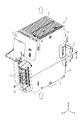
- FIG. 1 is an external perspective view of an electronic device housing according to the present embodiment, viewed obliquely from above;
- FIG. 1 is an external perspective view of an electronic device housing according to the present embodiment, viewed obliquely from below.
- FIG. 1 is an internal perspective view of an electronic device housing according to the present embodiment, viewed obliquely from above.
- the perspective view of the heat-conducting member according to the present embodiment as viewed diagonally from below.
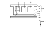
- Schematic diagram of AA cross section for explaining the first configuration example of the heat conduction member according to the present embodiment
- Schematic diagram of AA cross section for explaining a second configuration example of the heat conducting member according to the present embodiment
- Schematic diagram of AA cross section for explaining the third configuration example of the heat conducting member according to the present embodiment
- the internal perspective view of the electronic device housing including the heat-conducting member of the fourth configuration example according to the present embodiment.
- FIG. 1 shows an external perspective view of an electronic device housing 1 according to the present embodiment as seen obliquely from above.
- FIG. 2 shows an external perspective view of the electronic equipment housing 1 according to the present embodiment as viewed obliquely from below.
- the electronic device housing 1 includes a substantially rectangular parallelepiped body case 2 .
- the body case 2 includes an air supply surface 3 and an exhaust surface 4 facing each other.
- the intake surface 3 and the exhaust surface 4 have at least one hole through which air passes.
- the air naturally supplied through the holes in the air supply surface 3 is naturally discharged from the holes in the exhaust surface 4 .
- the air supply surface 3 may be read as the first surface
- the exhaust surface 4 may be read as the second surface.
- the axis extending from the air supply surface 3 toward the exhaust surface 4 is defined as the Z axis.
- the axis perpendicular to the Z-axis is defined as the X-axis.
- An axis perpendicular to the X-axis and the Z-axis is defined as the Y-axis.
- the positive direction of the Z-axis is "up”
- the negative direction of the Z-axis is "down”
- the positive direction of the X-axis is "forward”
- the negative direction of the X-axis is "back”
- the positive direction of the Y-axis is The direction may be called “left” and the negative direction of the Y-axis may be called “right”. It should be noted that these directions are used for convenience of explanation, and are not intended to limit the attitude of the structure in actual use.
- the main body case 2 is connected to the positive side of the X-axis of the air supply surface 3 and the exhaust surface 4 and connected to the front surface 5 perpendicular to the X-axis, and the negative side of the X-axis of the air supply surface 3 and the exhaust surface 4. a rear surface 6 opposite the front surface 5;
- the main body case 2 has a left side 7 connected to the side of the air supply surface 3 and the exhaust surface 4 in the negative direction of the Y axis and perpendicular to the Y axis, and a positive direction of the Y axis of the air supply surface 3 and the exhaust surface 4. and a right side face 8 connected to the side of the left side face 7 facing the left side face 7 .
- a mounting member 10 for mounting the main body case 2 to a rail 9 (for example, a DIN rail) is provided on the rear surface 6 of the main body case 2. As shown in FIG.
- FIG. 3 shows an AA cross-sectional view of the electronic equipment housing 1 shown in FIG.
- FIG. 4 shows an internal perspective view of the electronic equipment housing 1 according to the present embodiment as seen obliquely from above.
- FIG. 5 is a perspective view of the heat-conducting member 30 according to the present embodiment as viewed obliquely from below.
- the body case 2 of the electronic device housing 1 accommodates a substrate 20, an electronic device 21, a heat transfer sheet 22, and a heat transfer member 30.
- the board 20 is a so-called printed board, and has a plate shape extending from the air supply surface 3 toward the exhaust surface 4 .
- the board 20 may be arranged along the left side 7 or the right side 8 of the main body case 2 (for example, substantially parallel).
- the surface closer to the left side 7 of the body case 2 is called the front side
- the side closer to the right side 8 of the body case 2 is called the back side.
- the electronic device 21 is placed on the surface of the substrate 20.
- Examples of the electronic device 21 include a PLC (Programmable Logic Controller), SoC (System on a Chip), CPU (Central Processing Unit), or a processor.
- the surface closer to substrate 20 is referred to as the back surface, and the surface farther from substrate 20 is referred to as the front surface.
- the electronic device 21 generates heat when driven. Therefore, the electronic device 21 may be read as a heat-generating member, a heat-generating body, or a heat source.
- the heat transfer sheet 22 is a thin sheet with insulation and high thermal conductivity.
- the thermal conductivity of the heat transfer sheet 22 may be higher than that of the electronic device 21 .
- the heat transfer sheet 22 is arranged so as to contact the entire surface of the electronic device 21 .
- the surface that contacts the electronic device 21 is referred to as the back surface, and the surface that does not contact the electronic device 21 is referred to as the front surface.
- the heat-conducting member 30 is a member that has high thermal conductivity, conducts heat conducted from the electronic device 21 and/or the heat-conducting sheet 22, and dissipates the heat to the surrounding air.
- the thermal conductivity of the thermally conductive member 30 may be higher than that of the electronic device 21 or the thermally conductive sheet 22 .
- the heat conducting member 30 is made of a metal material having high thermal conductivity.
- the heat conducting member 30 includes a first heat conducting member 31, a second heat conducting member 32, and a third heat conducting member 33, as shown in FIGS.
- the first heat conducting member 31 is a plate-shaped member extending from the air supply surface 3 toward the exhaust surface 4 (that is, in the Z-axis direction).
- the heat conducting member 30 is arranged such that the first heat conducting member 31 is in contact with the entire surface of the heat conducting sheet 22 . That is, the first thermally conductive member 31 indirectly contacts the surface of the electronic device 21 .
- the size of the main surface of the first heat transfer member 31 may be equal to or larger than the size of the surface of the heat transfer sheet 22 .
- the surface that contacts the heat transfer sheet 22 is referred to as the back surface
- the surface that does not contact the heat transfer sheet 22 is referred to as the front surface.
- the second thermally conductive member 32 is fixed to the surface of the first thermally conductive member 31 and has a predetermined thickness in the direction perpendicular to the substrate 20 (that is, the Y-axis direction).
- the second heat conducting member 32 has a through hole 34 penetrating from the air supply surface 3 toward the exhaust surface 4 (that is, in the Z-axis direction).
- the number of through-holes 34 may be one, or may be plural as shown in FIGS.
- the third heat conducting member 33 is a plate-shaped member extending from the air supply surface 3 toward the exhaust surface 4 (that is, in the Z-axis direction).
- the third heat-conducting member 33 is fixed to the opposite side of the second heat-conducting member 32 to the first heat-conducting member 31 .
- the third heat-conducting member 33 may be arranged along (for example, substantially parallel to) the first heat-conducting member 31 or the substrate 20 .
- the back surface the surface that is fixed to the second thermally conductive member 32
- the back surface that is not fixed to the second thermally conductive member 32 is referred to as the back surface. called surface.
- the first heat conduction member 31, the second heat conduction member 32, and the third heat conduction member 33 may be configured as one member.
- the first heat-conducting member 31 and the second heat-conducting member 32 may be configured as one member, and the third heat-conducting member 33 may be configured as a separate member.
- the second heat-conducting member 32 and the third heat-conducting member 33 may be configured as one member, and the first heat-conducting member 31 may be configured as a separate member.
- the first heat conduction member 31, the second heat conduction member 32, and the third heat conduction member 33 may be configured as separate members.
- the thermal conductivity of the second thermally conductive member 32 is lower than the thermal conductivity of the first thermally conductive member 31
- the thermal conductivity of the third thermally conductive member 33 is less than the thermal conductivity of the second thermally conductive member 32 .
- rate may be lower than This is because the amount of heat to be dissipated decreases as the distance from the electronic device 21, which is the heat source, decreases.
- the amount of heat to be transferred (heat transfer area x thermal conductivity) can be reduced as the distance from the heat source increases.
- a material with high thermal conductivity may be used.
- a material with low thermal conductivity may be used.
- the right side surface 8 of the main body case 2 As shown in FIGS. 3 and 4, in the electronic device housing 1 according to the present embodiment, the right side surface 8 of the main body case 2, the substrate 20, the heat transfer element 20, and the heat transfer element are arranged in order from the negative direction to the positive direction of the Y axis.
- the sheet 22, the first heat conducting member 31, the second heat conducting member 32, the third heat conducting member 33, and the left side surface 7 of the main body case 2 are arranged.
- the electronic device housing 1 does not have to include the heat transfer sheet 22 .
- the back surface of the first thermally conductive member 31 may be in direct contact with the entire surface of the electronic device 21 .
- the electronic device 21 generates heat when driven.
- the heat generated from the electronic device 21 is conducted to the first heat conducting member 31 through the heat transfer sheet 22 .
- the heat conducted to the first heat conducting member 31 is conducted to the second heat conducting member 32 .
- the heat conducted to the second heat conducting member 32 is radiated to the air inside the through hole 34 and also conducted to the third heat conducting member 33 .
- the heat conducted to the third heat-conducting member 33 is radiated to the air from the front and back surfaces of the third heat-conducting member 33 .
- the heat generated from the electronic device 21 is radiated into the air inside the main body case 2 by the first heat conducting member 31, the second heat conducting member 32, and the third heat conducting member 33.
- the air in the through-holes 34 of the second heat-conducting member 32 is warmed by heat radiation, the air is naturally supplied from the air-supply surface 3 of the main body case 2 due to the chimney effect, and passes through the through-holes 34 to A naturally discharged airflow is generated from the exhaust surface 4 of the main body case 2 (see the dotted arrow in the drawing).
- This airflow passes over the back surface of the third heat conducting member 33 .
- the heat radiated into the air from the first heat conducting member 31, the second heat conducting member 32, and the third heat conducting member 33 is carried out of the main body case 2 by the airflow. Therefore, the heat discharge capability of the heat generated in the main body case 2 is enhanced. In other words, the heat generated in the electronic device housing 1 that accommodates the electronic device 21 can be efficiently dissipated.
- FIG. 6 is a schematic diagram of the AA cross section for explaining the first structural example of the heat conducting member 30 according to the present embodiment.
- the length of the through hole 34 formed in the second heat conducting member 32 in the direction perpendicular to the substrate 20 (that is, the Y-axis direction) (hereinafter referred to as the vertical length T of the through hole 34) is It may be longer than the plate thickness d1 of the first heat conducting member 31 . Thereby, the heat conducted from the first heat conducting member 31 to the second heat conducting member 32 is sufficiently radiated to the air inside the through hole 34 .
- the vertical length T of the through hole 34 may be equal to or greater than the length of the through hole 34 in the direction parallel to the substrate 20 (hereinafter referred to as the horizontal length W of the through hole 34).
- the vertical length T of the through hole 34 may be 1.0 to 1.5 times the horizontal length W of the through hole 34 .
- cross-sectional shape of the through-hole 34 is square in FIG. 6, the cross-sectional shape of the through-hole 34 may be a shape with rounded corners as shown in FIGS. This also applies to FIGS. 7 and 8, which will be described later.
- FIG. 7 is a schematic view of the AA cross section for explaining the second configuration example of the heat conducting member 30 according to the present embodiment.
- the lateral length W1 near the third heat conducting member 33 is longer than the lateral length W2 near the first heat conducting member 31.
- the lateral length W of the through-hole 34 may widen from the first heat conducting member 31 toward the third heat conducting member 33 .
- the temperature of the air in the through-holes 34 rises, the flow velocity of the air in the through-holes 34 increases, and the chimney effect improves. Therefore, the heat exhausting ability in the main body case 2 is improved.
- the heat conducting member 30 may have a configuration including features of both the second configuration example and the first configuration example, as shown in FIG.
- the heat conducting member 30 may have a configuration including only the features of the second configuration example.
- FIG. 8 is a schematic view of the AA cross section for explaining the third configuration example of the heat conducting member 30 according to the present embodiment.
- the third heat conducting member 33 extends along the substrate 20 (for example, and a third extension 35 extending away from the second heat conducting member 32 (substantially parallel). As a result, the surface area of the third heat conducting member 33 is increased, and the heat dissipation capability is improved.
- the plate thickness d2 of the third heat conducting member 33 may be shorter than the plate thickness d1 of the first heat conducting member 31. Additionally, the surface area of the third heat conducting member 33 may be greater than the surface area of the first heat conducting member 31 or the second heat conducting member 32 . This improves the heat dissipation capability of the heat conducting member 30 and reduces the weight of the heat conducting member 30 .
- the plate thickness d3 at the position farther from the second heat conducting member 32 is closer to the second heat conducting member 32 . It may be shorter than the plate thickness d4 of .
- the plate thickness of the third extending portion 35 of the third heat conducting member 33 may narrow as the distance from the second heat conducting member 32 increases. This makes the heat conducting member 30 lighter.
- the heat conducting member 30 may have a configuration including all the features of the third configuration example, the second configuration example, and the first configuration example, as shown in FIG.
- the heat conducting member 30 may have a configuration including two features of the third configuration example, the second configuration example, and the first configuration example.
- the heat conducting member 30 may have a configuration including only the features of the third configuration example.
- FIG. 9 is a perspective view showing a fourth configuration example of the heat conducting member 30 according to this embodiment.
- FIG. 10 is an internal perspective view of the electronic device housing 1 including the thermally conductive member 30 of the fourth configuration example according to the present embodiment. It should be noted that in FIG. 10 , in order to make the explanation easier to understand, the main body case 2 of the electronic device housing 1 and part of the components accommodated in the main body case 2 are omitted.
- the first heat conducting member 31 may extend toward the exhaust surface 4 of the main body case 2.
- the portion of the first heat conducting member 31 that extends toward the exhaust surface 4 of the main body case 2 will be referred to as a first extending portion 36 .
- the side E1 of the first heat conducting member 31 closer to the exhaust surface 4 of the first extending portion 36 is in contact with the portion of the first heat conducting member 31 excluding the first extending portion 36 of the heat transfer sheet 22. may be closer to the exhaust surface 4 than the side E2 closer to the exhaust surface 4 of .
- the second heat conducting member 32 may extend toward the exhaust surface 4 in accordance with the extension of the first extending portion 36 of the first heat conducting member 31 .
- the surface F of the second heat transfer member 32 closer to the exhaust surface 4 is formed by the side E2 of the heat transfer sheet 22 closer to the exhaust surface 4 and the first extension 36 of the first heat transfer member 31. It is positioned between the side E1 closer to the surface 4 and the side E1.
- the length of the through-hole 34 in the height direction (that is, the Z-axis direction) (that is, the length of the chimney) is increased, so that the temperature of the air inside the through-hole 34 rises, and the inside of the through-hole 34 becomes Increases the air velocity of the air and enhances the chimney effect. Therefore, the heat exhausting ability in the main body case 2 is improved.
- the second heat conducting member 32 may form ribs 37 whose thickness decreases in the direction of approaching the third heat conducting member 33 as the exhaust surface 4 is approached.
- the ribs 37 of the second heat-conducting member 32 increase the rigidity of the third heat-conducting member 33 .
- the electronic device housing 1 includes a rectangular parallelepiped body case 2 including a first surface (air supply surface 3) and a second surface (exhaust surface 4) facing each other and having holes through which air passes; A substrate 20 housed in the body case 2 and extending from the first surface to the second surface, an electronic device 21 mounted on the substrate 20, and a surface of the electronic device 21 opposite to the substrate 20.
- the plate-like first heat-conducting member 31 that indirectly contacts and conducts heat generated by the electronic device 21 is fixed to the surface of the first heat-conducting member 31 opposite to the surface that contacts the electronic device 21, and the substrate 20 (for example, the direction away from the first heat-conducting member 31) and has at least one through-hole 34 penetrating from the first surface to the second surface.
- a second heat-conducting member 32 that conducts heat conducted from the member 31, and a side of the second heat-conducting member 32 that is fixed to the first heat-conducting member 31 is fixed to the opposite side of the second heat-conducting member 32 from the first surface to the second surface.
- a plate-shaped third heat conduction member 33 extending toward and conducting heat conducted from the second heat conduction member 32 and an attachment member 10 for attaching the main body case 2 to a predetermined rail 9 are provided.
- the heat generated from the electronic device 21 is conducted to the first heat conduction member 31, the second heat conduction member 32, and the third heat conduction member 33, and the heat conduction member 31 and the second heat conduction member 32 and the third heat conducting member 33, the heat is radiated to the air inside the main body case 2.
- the temperature of the air in the through-holes 34 rises, and due to the chimney effect, an airflow is generated in which the air supplied from the first surface passes through the through-holes 34 and is exhausted from the second surface. Therefore, the high-temperature air inside the main body case 2 can be efficiently discharged to the outside of the main body case 2 . That is, the heat exhausting ability within the main body case 2 is improved, and the cooling ability of the electronic device 21 is enhanced.
- the first thermally conductive member 31 includes a first extension portion 36 extending toward the second surface, and the second surface of the first extension portion 36 is closer to the second surface than the side closer to the second surface of the heat transfer sheet 22, and the surface of the second heat transfer member 32 closer to the second surface is closer to the heat transfer sheet 22 and the side of the first extension portion 36 of the first thermally conductive member 31 closer to the second surface.
- the length of the through hole 34 formed in the second heat conducting member 32 is increased, thereby further enhancing the chimney effect. That is, the heat exhausting ability in the main body case 2 is further improved, and the cooling ability of the electronic device 21 is further improved.
- the length of the through hole 34 in the direction perpendicular to the substrate 20 (for example, the direction away from the first heat conduction member 31) is It may be longer than the thickness of the conductive member 31 .
- the flow velocity of the air in the through hole 34 is improved, further enhancing the chimney effect. That is, the heat exhausting ability in the main body case 2 is further improved, and the cooling ability of the electronic device 21 is further improved.
- the length (longitudinal length T) of the through hole 34 in the direction perpendicular to the substrate 20 may be longer than the length in the direction parallel to the substrate 20 (horizontal length W).
- the flow velocity of the air in the through hole 34 is improved, further enhancing the chimney effect. That is, the heat exhausting ability in the main body case 2 is further improved, and the cooling ability of the electronic device 21 is further improved.
- the third heat conduction member 33 In the electronic device housing 1 according to any one of Expressions 1 to 5, in a direction parallel to the substrate 20 in the through hole 34 (for example, a direction along the first heat conduction member 31), the third heat conduction member 33 The length (horizontal length W1) at the position closer to the first heat conducting member 31 (horizontal length W2) may be longer than the length (horizontal length W2) at the position closer to the first heat conducting member 31 . As a result, the flow velocity of the air in the through hole 34 is improved, further enhancing the chimney effect. That is, the heat exhausting ability in the main body case 2 is further improved, and the cooling ability of the electronic device 21 is further improved.
- the third heat-conducting member 33 is axially directed from the first surface (air supply surface 3) to the second surface (exhaust surface 4).
- a third extension 35 may be included that extends away from the second thermally conductive member 32 along the substrate 20 in the vertical direction. As a result, the surface area of the third heat conducting member 33 is increased, and the heat dissipation capability of the third heat conducting member 33 is enhanced.
- the present disclosure can efficiently exhaust the heat generated within the housing that houses the electronic device, and is therefore useful for suppressing temperature rise within the housing.
Landscapes
- Engineering & Computer Science (AREA)
- Physics & Mathematics (AREA)
- Theoretical Computer Science (AREA)
- Human Computer Interaction (AREA)
- General Engineering & Computer Science (AREA)
- General Physics & Mathematics (AREA)
- Thermal Sciences (AREA)
- Microelectronics & Electronic Packaging (AREA)
- Cooling Or The Like Of Electrical Apparatus (AREA)
Applications Claiming Priority (2)
| Application Number | Priority Date | Filing Date | Title |
|---|---|---|---|
| JP2021-105634 | 2021-06-25 | ||
| JP2021105634A JP7653646B2 (ja) | 2021-06-25 | 2021-06-25 | 電子機器用筐体 |
Publications (1)
| Publication Number | Publication Date |
|---|---|
| WO2022270145A1 true WO2022270145A1 (ja) | 2022-12-29 |
Family
ID=84545631
Family Applications (1)
| Application Number | Title | Priority Date | Filing Date |
|---|---|---|---|
| PCT/JP2022/018637 Ceased WO2022270145A1 (ja) | 2021-06-25 | 2022-04-22 | 電子機器用筐体 |
Country Status (2)
| Country | Link |
|---|---|
| JP (1) | JP7653646B2 (https=) |
| WO (1) | WO2022270145A1 (https=) |
Families Citing this family (3)
| Publication number | Priority date | Publication date | Assignee | Title |
|---|---|---|---|---|
| JP2024100258A (ja) * | 2023-01-13 | 2024-07-26 | 株式会社三洋物産 | 遊技機 |
| JP2024100261A (ja) * | 2023-01-13 | 2024-07-26 | 株式会社三洋物産 | 遊技機 |
| JP2024100259A (ja) * | 2023-01-13 | 2024-07-26 | 株式会社三洋物産 | 遊技機 |
Citations (2)
| Publication number | Priority date | Publication date | Assignee | Title |
|---|---|---|---|---|
| JP2009231511A (ja) * | 2008-03-21 | 2009-10-08 | Sharp Corp | 筐体 |
| JP2017199770A (ja) * | 2016-04-27 | 2017-11-02 | 株式会社コンテック | ヒートシンクおよび筐体 |
Family Cites Families (1)
| Publication number | Priority date | Publication date | Assignee | Title |
|---|---|---|---|---|
| JP2009283064A (ja) * | 2008-05-21 | 2009-12-03 | I-O Data Device Inc | 記憶装置収納筐体の放熱構造 |
-
2021
- 2021-06-25 JP JP2021105634A patent/JP7653646B2/ja active Active
-
2022
- 2022-04-22 WO PCT/JP2022/018637 patent/WO2022270145A1/ja not_active Ceased
Patent Citations (2)
| Publication number | Priority date | Publication date | Assignee | Title |
|---|---|---|---|---|
| JP2009231511A (ja) * | 2008-03-21 | 2009-10-08 | Sharp Corp | 筐体 |
| JP2017199770A (ja) * | 2016-04-27 | 2017-11-02 | 株式会社コンテック | ヒートシンクおよび筐体 |
Also Published As
| Publication number | Publication date |
|---|---|
| JP7653646B2 (ja) | 2025-03-31 |
| JP2023004123A (ja) | 2023-01-17 |
Similar Documents
| Publication | Publication Date | Title |
|---|---|---|
| WO2022270145A1 (ja) | 電子機器用筐体 | |
| CN105074908B (zh) | 冷却装置及使用该冷却装置的带冷却装置功率模块 | |
| JP5899473B2 (ja) | 電子機器の冷却構造 | |
| US12218027B2 (en) | Electrical device and electronic control device with housings having fin arrangement and fan for air flow | |
| JP7565804B2 (ja) | 放熱構造 | |
| WO2017208487A1 (ja) | 電子デバイス及び電子デバイスの放熱構造 | |
| CN111083252B (zh) | 电子设备 | |
| JP2018195633A (ja) | 電子機器 | |
| JP3675607B2 (ja) | 電子機器の放熱構造 | |
| CN201115228Y (zh) | 一体成型的散热壳体结构 | |
| CN104010474B (zh) | 具备包含散热器的冷却构造部的伺服放大器 | |
| CN100512613C (zh) | 有功元件冷却装置 | |
| CN108601299B (zh) | 屏蔽罩及包含其的屏蔽罩组件 | |
| JP2009059760A (ja) | 電子回路基板の放熱構造体 | |
| WO2017187898A1 (ja) | ヒートシンクおよび筐体 | |
| JP7675595B2 (ja) | 半導体モジュール | |
| CN113745001B (zh) | 控制器的电容元件散热结构 | |
| WO2022201715A1 (ja) | 電子機器用筐体 | |
| JP2006339223A (ja) | Cpuの放熱構造 | |
| JP7619156B2 (ja) | 電子制御装置 | |
| US12621954B2 (en) | Electronic device | |
| JP5992235B2 (ja) | 制御装置 | |
| CN222424553U (zh) | 电源模块 | |
| TW201343061A (zh) | 散熱構造 | |
| US20240164045A1 (en) | Electronic device |
Legal Events
| Date | Code | Title | Description |
|---|---|---|---|
| 121 | Ep: the epo has been informed by wipo that ep was designated in this application |
Ref document number: 22828064 Country of ref document: EP Kind code of ref document: A1 |
|
| NENP | Non-entry into the national phase |
Ref country code: DE |
|
| 122 | Ep: pct application non-entry in european phase |
Ref document number: 22828064 Country of ref document: EP Kind code of ref document: A1 |