WO2022269980A1 - 外界認識装置、および、外界認識方法 - Google Patents
外界認識装置、および、外界認識方法 Download PDFInfo
- Publication number
- WO2022269980A1 WO2022269980A1 PCT/JP2022/004712 JP2022004712W WO2022269980A1 WO 2022269980 A1 WO2022269980 A1 WO 2022269980A1 JP 2022004712 W JP2022004712 W JP 2022004712W WO 2022269980 A1 WO2022269980 A1 WO 2022269980A1
- Authority
- WO
- WIPO (PCT)
- Prior art keywords
- vehicle
- external world
- recognition device
- unit
- world recognition
- Prior art date
- Legal status (The legal status is an assumption and is not a legal conclusion. Google has not performed a legal analysis and makes no representation as to the accuracy of the status listed.)
- Ceased
Links
Images











Classifications
-
- G—PHYSICS
- G06—COMPUTING OR CALCULATING; COUNTING
- G06T—IMAGE DATA PROCESSING OR GENERATION, IN GENERAL
- G06T7/00—Image analysis
- G06T7/70—Determining position or orientation of objects or cameras
- G06T7/73—Determining position or orientation of objects or cameras using feature-based methods
-
- B—PERFORMING OPERATIONS; TRANSPORTING
- B60—VEHICLES IN GENERAL
- B60W—CONJOINT CONTROL OF VEHICLE SUB-UNITS OF DIFFERENT TYPE OR DIFFERENT FUNCTION; CONTROL SYSTEMS SPECIALLY ADAPTED FOR HYBRID VEHICLES; ROAD VEHICLE DRIVE CONTROL SYSTEMS FOR PURPOSES NOT RELATED TO THE CONTROL OF A PARTICULAR SUB-UNIT
- B60W30/00—Purposes of road vehicle drive control systems not related to the control of a particular sub-unit, e.g. of systems using conjoint control of vehicle sub-units
- B60W30/14—Adaptive cruise control
- B60W30/16—Control of distance between vehicles, e.g. keeping a distance to preceding vehicle
-
- G—PHYSICS
- G06—COMPUTING OR CALCULATING; COUNTING
- G06V—IMAGE OR VIDEO RECOGNITION OR UNDERSTANDING
- G06V20/00—Scenes; Scene-specific elements
- G06V20/50—Context or environment of the image
- G06V20/56—Context or environment of the image exterior to a vehicle by using sensors mounted on the vehicle
- G06V20/58—Recognition of moving objects or obstacles, e.g. vehicles or pedestrians; Recognition of traffic objects, e.g. traffic signs, traffic lights or roads
-
- G—PHYSICS
- G08—SIGNALLING
- G08G—TRAFFIC CONTROL SYSTEMS
- G08G1/00—Traffic control systems for road vehicles
- G08G1/16—Anti-collision systems
- G08G1/167—Driving aids for lane monitoring, lane changing, e.g. blind spot detection
-
- G—PHYSICS
- G06—COMPUTING OR CALCULATING; COUNTING
- G06T—IMAGE DATA PROCESSING OR GENERATION, IN GENERAL
- G06T2207/00—Indexing scheme for image analysis or image enhancement
- G06T2207/10—Image acquisition modality
- G06T2207/10016—Video; Image sequence
- G06T2207/10021—Stereoscopic video; Stereoscopic image sequence
-
- G—PHYSICS
- G06—COMPUTING OR CALCULATING; COUNTING
- G06T—IMAGE DATA PROCESSING OR GENERATION, IN GENERAL
- G06T2207/00—Indexing scheme for image analysis or image enhancement
- G06T2207/30—Subject of image; Context of image processing
- G06T2207/30248—Vehicle exterior or interior
- G06T2207/30252—Vehicle exterior; Vicinity of vehicle
- G06T2207/30261—Obstacle
Definitions
- the present invention relates to an external world recognition device and an external world recognition method used during vehicle control such as following a preceding vehicle.
- the problem is described as "to provide an object detection method and an object detection device for early determination of interruption", and as a solution, "the object detection device 100 can 50, and a controller 20.
- the controller 20 extracts a plurality of feature points from the image, and extracts a plurality of feature points from the plurality of feature points to form a moving object.
- the controller 20 calculates the variance of the motion vectors of the plurality of feature points that form the moving object from the plurality of images acquired at different times.
- the controller 20 calculates the components of the motion vectors in the road width direction. is equal to or greater than the threshold, it is determined that the moving object may cut into the lane in which the host vehicle is traveling.”
- the optical flow calculation unit 22 calculates an optical flow from the feature points of the past image and the feature points of the current image.
- the motion is represented by a vector, and the optical flow calculator 22 detects current feature points corresponding to the same object in the real space as the past feature points, as related feature points.
- the flow calculation unit 22 calculates a combination of past feature points and current feature points that are related to each other as an optical flow.”
- the object detection device of Patent Document 1 recognizes another vehicle that cuts in front of the vehicle by utilizing the optical flow in the stereo image.
- Patent Document 1 When the interrupt determination unit 28 determines that there is a possibility that another vehicle may cut in, the vehicle control unit 30 brakes the own vehicle so that the occupant does not feel uncomfortable, for example. In addition, the vehicle control unit 30 may brake the host vehicle so that the passenger does not feel uncomfortable even when the interrupt determination unit 28 determines that another vehicle will cut in.”. That is, in Patent Document 1, when there is a possibility that another vehicle will cut in or when it is determined that another vehicle will cut in, the own vehicle is braked regardless of the mode of the cut. However, even if there is an approaching vehicle, if it is not possible to accurately determine whether or when contact is likely to occur based on the contour shape and speed vector of the approaching vehicle, the occupants will feel uncomfortable. It is clear that it is the control that gives.
- the present invention provides an external world recognition device and an external world recognition method that, when a vehicle cuts in between the preceding vehicle and the host vehicle, recognizes the vehicle as a vehicle based on the side information of the vehicle. intended to provide If there is a possibility of contact with the interrupting vehicle, the own vehicle is braked, and if there is no possibility of contact, the vehicle to be followed in the preceding vehicle tracking control is switched from the previous preceding vehicle to the interrupting vehicle for stability. It is an object of the present invention to provide an external world recognition device and an external world recognition method capable of continuing running in a relaxed state.
- a side extraction unit for extracting side information of the other vehicle from the images based on parallax between left and right images of a part of another vehicle approaching the own vehicle; a shape fitting unit that fits a rectangular parallelepiped shape similar to the other vehicle in the image based on the side information and the back position; and using the rectangular parallelepiped shape, the and an other vehicle recognition unit that recognizes another vehicle as a vehicle ahead of the host vehicle.
- the interrupting vehicle when an interrupting vehicle cuts in between the preceding vehicle and the host vehicle, the interrupting vehicle can be recognized as a vehicle based on the side information of the interrupting vehicle. If there is a possibility of contact with the interrupting vehicle, the own vehicle is braked, and if there is no possibility of contact, the vehicle to be followed in the preceding vehicle tracking control is switched from the previous preceding vehicle to the interrupting vehicle for stability. You can continue running.
- Functional block diagram of the external world recognition device of one embodiment Bird's-eye view of the cut-in scene between the preceding vehicle and the own vehicle Environment in front of own vehicle in a cut-in scene between preceding vehicle and own vehicle
- An example of UD space after disparity value voting Explanatory diagram of three-dimensional object candidates extracted from the UD space in FIG.
- Functional block diagram of preceding vehicle identification unit Functional block diagram of side extractor Explanatory drawing of line segment parallel to own vehicle course extracted from UD space of FIG.
- FIG. 1 is a front view of an own vehicle V0 to which an external world recognition device 100 according to an embodiment of the present invention is attached
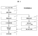
- FIG. 2 is a functional block diagram of the external world recognition device 100 of FIG.
- the external world recognition device 100 is attached to the upper inner surface of the windshield of the own vehicle V0, and recognizes the environment ahead of the own vehicle V0 during vehicle control such as preceding vehicle following control (ACC). It is a device for
- each unit other than the stereo camera unit 1 is, specifically, a computer having hardware such as an arithmetic unit such as a CPU, a storage device such as a semiconductor memory, and a communication device. is a unit.
- a computer having hardware such as an arithmetic unit such as a CPU, a storage device such as a semiconductor memory, and a communication device. is a unit.
- Each function described above is realized by executing the program stored in the storage device by the arithmetic device. In the following, the details of each part will be sequentially described while omitting such well-known techniques in the computer field as appropriate. do.
- the stereo camera section 1 is composed of a left camera 1L and a right camera 1R directed toward the front of the vehicle, and an image processing section.
- the image processing unit generates parallax images (information obtained by two-dimensionally arranging the parallax values D of the left and right images) by performing well-known stereo matching processing on the left image PL and the right image PR captured by the image sensors of each camera. and outputs this as three-dimensional information of the front of the vehicle.
- the stereo camera unit 1 is used to generate three-dimensional information, but instead of the stereo camera unit 1, a monocular camera or another type of front sensor such as a lidar may be used to generate three-dimensional information. can be used to generate three-dimensional information.
- parallax voting unit 2 a parallax value, which is the result of stereo matching in the stereo camera unit 1, is placed in a parallax voting space (hereinafter referred to as “UD space”) having a parallax value D on the vertical axis and an image abscissa U on the horizontal axis. Vote D.
- UD space parallax voting space
- the parallax value D can be converted into the depth distance to the captured object. Therefore, in addition to the magnitude of the parallax value D, the depth distance Perspective is also shown.
- FIG. 4 is a UD space in which parallax values D of parallax images output by the stereo camera unit 1 are voted under the environment of FIG. 3B.
- the parallax voting unit 2 votes the parallax value D for each pixel row in the UD space while scanning the parallax value D in the vertical direction one pixel row at a time (or at each pixel row) from one end of the parallax image. completes the UD space as shown in FIG.
- the parallax image includes a three-dimensional object
- the parallax value D is almost the same value in the same depth distance portion of the three-dimensional object. Concentrate votes.
- the voting concentration of the parallax value D is displayed with high luminance (dark white).
- the back surface extraction unit 3 detects a three-dimensional object based on the UD space ( FIG. 4 ) obtained by the parallax voting unit 2 .
- the voting concentration of the parallax value D is aligned in the horizontal direction in the UD space.
- the extraction unit 3 scans the UD space in the horizontal direction and extracts a high luminance area that is long in the horizontal direction, thereby making it possible to detect a three-dimensional object candidate (back surface).
- the outline of the processing of the back surface extraction unit 3 will be described below with reference to FIGS. 5A and 5B.
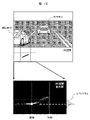
- FIG. 5A is a diagram in which the back surface extraction unit 3 scans the UD space in FIG. be.
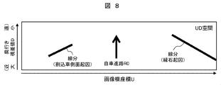
- the UD space in FIG. 5A originally includes the luminance information shown in FIG. 4, in order to emphasize the object of explanation in FIG. 5A, the luminance information is omitted in FIG. it's shown. This treatment is the same in the UD space such as FIG. 8, which will be described later.
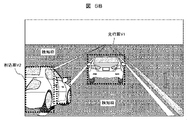
- the back surface extraction unit 3 When the three-dimensional object candidates shown in FIG. 5A are extracted, the back surface extraction unit 3 normally extracts three-dimensional objects such as the back surface of the preceding vehicle V1 moving parallel to the own vehicle V0, as indicated by the detection frame in the image of FIG. 5B. can do. On the other hand, for a three-dimensional object such as a cut-in vehicle V2 that moves in a direction not parallel to the own vehicle V0, the back surface extraction unit 3 separates the back surface and side surfaces of the cut-in vehicle V2 in the image from each other as an independent three-dimensional object. There is a possibility of false detection.
- the back surface extraction unit 3 extracts two three-dimensional objects whose size, position, orientation, speed, etc. are unstable.
- the back surface extracting unit 3 chronologically tracks the detection frame of the three-dimensional object (dotted line in FIG. 5B) extracted in each frame of the continuously captured images, and when tracked as a stable horizontal position and depth, Determined as a stable three-dimensional object. Then, only objects that are stable in time series and can be tracked as three-dimensional objects are used in subsequent processing, and objects that are not stable in time series are eliminated as noise factors. For this reason, like the side of the cut-in vehicle V2, the detection frame for an unstable object is not stable in time series and cannot be used as a three-dimensional object. Even if it can be tracked to some extent, the position, attitude, speed, etc. are unstable, and there are many cases where it is not a correct target for alarms or control. In order to suppress false alarms and erroneous control, it is necessary to design so that control is not performed for objects with unstable positions and velocities.
- the cut-in vehicle V2 in which the back surface and part of the side surface are imaged at the same time, is cut in at a steep angle from a short distance, especially in a traffic jam, so the entire object cannot be imaged. It was difficult to accurately recognize the cut-in vehicle V2.
- the preceding vehicle identification unit 4 extracts a three-dimensional object that can be stably extracted in chronological order from the three-dimensional object candidates extracted by the back surface extraction unit 3 (for example, a three-dimensional object candidate caused by the preceding vehicle V1 in FIG. 5A). is selected, and further processing is performed to determine whether or not it is a vehicle from the size and appearance on the image.
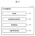
- the preceding vehicle identifying section 4 has a tracking section 41, a vehicle rear surface candidate selecting section 42, a vehicle identifying section 43, and a position/speed estimating section 44 shown in FIG. Each part will be described in order below.
- the tracking unit 41 performs tracking processing on a three-dimensional object whose position and size are stable in time series in the continuously captured images, and simply calculates the position and speed.
- the vehicle back surface candidate selection unit 42 selects a vehicle back surface candidate by selecting a three-dimensional object having a possible size and speed as a vehicle from among the three-dimensional objects being tracked.
- the vehicle identification unit 43 performs identification processing on the selected three-dimensional object candidate with a size that seems to be the back of the vehicle, and identifies whether it is a car. Specifically, identification processing is performed for each frame, and a three-dimensional object with a high identification score for several consecutive frames is finally identified as a vehicle.
- the position/speed estimation unit 44 highly accurately estimates the position and speed of the three-dimensional object identified as a vehicle.
- the external world recognition device 100 of the present embodiment additionally includes a side surface extraction unit 6 and a right angle fitting unit 7, which will be described below.
- the side extraction unit 6 uses the UD space illustrated in FIG. 4 to search for side candidates of the cut-in vehicle V2.
- the side surface extraction unit 6 has a side surface candidate line search unit 61, a vehicle candidate determination unit 62, a tracking unit 63, and a side velocity analysis unit 64 shown in FIG. Each part will be described in order below.
- a line segment extending along the own vehicle course R0 as shown in FIG. A line segment within a predetermined angle with respect to the line) is searched.
- a line segment caused by the side surface of the cutting-in vehicle V2 is searched, and on the right side of the course R0, a line segment caused by a curbstone is searched. ing.
- a line segment with an inclination of about ⁇ 50° with respect to the course R0 of the own vehicle is searched so that the side of the cutting-in vehicle V2 that cuts into the course R0 of the own vehicle can be searched.
- the angle "50°” is not an angle in the UD space of Fig. 4 or an actual image as in Fig. 3B, but an actual relative attitude of the vehicle in the bird's-eye view (see Fig. 3A). means.
- the reason why the angle of the line segment to be searched is limited is that even in the process of searching for the back face, a certain degree of inclination of the back face is supported.
- a separate countermeasure is taken as a countermeasure for a collision accident.
- a separate countermeasure is taken as a countermeasure for a collision accident.
- an interrupting vehicle V2 including a motorcycle is detected, and a line segment existing on the side of the own vehicle is searched for, for example, with a length of 1.5 m or more and 15 m or less.
- the UD space there are many three-dimensional objects other than vehicles on the side, such as road shoulders and walls of buildings, so multiple sides can be searched.
- considering the safety of the own vehicle V0 it is only necessary to consider even the closest object.
- the side candidate line searching unit 61 detects approximate lateral positions where the short-range cut-in vehicle V2 is likely to cut in from the UD space in FIG.
- a large number of line segments parallel to the course R0 of the vehicle on the overhead view are set in the UD space (FIG. 4).
- a histogram is generated by accumulating the number of votes of the parallax value D on the line.
- the number of votes accumulated on the line is greater than at other positions.
- a peak (maximum value) of the cumulative number of votes occurs at the position of the horizontal axis (image horizontal coordinate U) corresponding to this line segment.
- a mountain where the number of votes equal to or greater than the threshold has accumulated is searched outward from the course R0 (center) of the vehicle.
- the processing here is for searching for a three-dimensional object that comes into contact with the own vehicle V0 or a three-dimensional object that directly affects the vehicle behavior of the own vehicle V0.
- the mountain caused by the side surface of the car V2) is extracted, the search processing to the outside is stopped, and it is determined that the mountain is likely to be a three-dimensional object having a side surface. Analysis may be performed.
- FIG. 9(4) a line segment (diagram 9(1) with dashed-dotted line arrow).
- FIG. 9(5) many line segments are set around the line segment selected in FIG. Similar to (2), a histogram is generated in which the number of votes for the parallax value D is accumulated. Then, the line with the largest cumulative amount of votes on the line (for example, the dashed-dotted line arrow in FIG. 9(5)) is extracted as the side candidate line.
- the vehicle candidate determination unit 62 tentatively determines the length of the side surface based on the extracted side surface candidate lines. For example, if the vote value on the side candidate line is above a certain threshold three times in a row, the line segment starts from the first vote, and if it falls below the threshold twice in the middle, the line segment continues. If the length is checked by tracing the line segment and falls below the 3 consecutive threshold, the point before the 3 consecutive points is registered as the end point of the line segment. If the length of the line segment obtained in this way is 1.5 m or more, which corresponds to the side length of a motorcycle, and 15 m or less, which corresponds to the side length of a large truck, then the line segment is considered as a vehicle candidate. Extract minutes.
- the length is out of this range, it is excluded from the side candidate lines of the vehicle as noise, road shoulders, walls, or the like. Furthermore, if it is determined to be a side candidate line of a vehicle, it is assumed that the length is 1 m or more and the effective parallax is about 40% or more. Confirm that 40% of the assumed voting amount exists. Partially below 40% is allowed, and vehicle candidates are determined after confirming that the above 40% is exceeded on average. In a situation where votes are not collected, it is determined that the object is an object such as a road shoulder that is short from the road surface and not a vehicle including a two-wheeled vehicle.
- the tracking unit 63 tracks the side candidate lines selected by the vehicle candidate determination unit 62 .
- line segments that do not meet the criteria for length and height in the vehicle candidate determination unit 62 are also tracked, thereby reducing interruptions in tracking due to tracking failures. process.
- the lateral velocity analysis unit 64 calculates the velocity (depth direction velocity, lateral movement direction velocity) of the lateral candidate line tracked by the tracking part 63 . Furthermore, the side velocity analysis unit 64 performs stabilization in time series to determine whether the extracted side surface candidate line is approaching the vehicle V0. The approaching side determination is performed every frame.
- the rectangular shape fitting unit 7 performs detailed fitting of the rectangular shape only to the side surface candidate lines extracted by the side surface extraction unit 6, thereby reducing the computational processing load and accurately extracting the contour shape of the cut-in vehicle V2. do.
- the right angle fitting unit 7 also calculates the position and speed of the cut-in vehicle V2, and determines whether the cut-in vehicle V2 should be monitored in order for the own vehicle V0 to continue safe and comfortable driving.
- the interrupting vehicle V2 that is determined to be monitored is mainly for (1) the interrupting vehicle V2 that may come into contact with the host vehicle V0 if it does not take measures such as emergency braking or emergency avoidance, ( 2) There are two modes: a cut-in vehicle V2 that may approach to less than a safe inter-vehicle distance unless the host vehicle V0 decelerates.
- the rectangular shape fitting section 7 includes a side tip fitting section 71, a side rear end fitting section 72, a side base rear surface searching section 73, a detection base line switching section 74, and a rear base , a detailed shape fitting unit 76, a feature point tracking/velocity estimating unit 77, and a vehicle identifying unit 78. Each part will be described below in order.
- the side tip fitting unit 71 searches for the tip of the cut-in vehicle V2 in detail. Therefore, the side tip fitting unit 71 executes a method of finding the tip based on the distance using parallax or a method of finding the tip based on the texture.
- the depth of the tip of the cut-in vehicle V2 on the original image is measured using the parallax image, with the side tip position (initial value) extracted in the UD space as a reference. do.
- the front end position of the vehicle body is specified using the depth difference between the vehicle body and the road surface in the parallax image.
- the dashed-dotted line On the left side of , the parallax value D corresponding to the depth distance to the side of the vehicle body is calculated, while on the right side of the dashed line, the parallax value D corresponding to the depth distance to the road surface farther from the side of the vehicle body is calculated. Therefore, a large difference occurs in the parallax value D (depth distance) between the left and right of a certain position. By extracting the boundary where this difference occurs as a more accurate position of the leading edge of the vehicle, it is possible to search for the accurate leading edge of the cut-in vehicle V2.
- a method of separating by texture a method of extracting boundaries from differences in luminance and color information may be used, a method of dividing similar textures into small regions may be used, and semantic segmentation may be used. It is also possible to use a method to A technique that uses both parallax and luminance to improve stability may be utilized.
- ⁇ Side rear end fitting portion 72 In the side rear end fitting unit 72, the rear end position is again fitted to the already extracted line segment of the side of the cut-in vehicle V2. Even if the vehicle V2 cuts in front of the own vehicle V0, it basically cuts in while running parallel to the own vehicle V0. If the rear end of the cut-in vehicle V2 enters to some extent, the parallax of at least the rear end (back surface) of the vehicle should be seen as a parallax voting value (high brightness area) lined up substantially horizontally in the UD space. Of course, if the cut-in angle is too sharp, this may not be the case and the voting line may be slightly tilted, but basically the rear parallax of the car body will be lined up in the horizontal direction of the UD space. .
- analysis is performed by accumulating voting values in the lateral direction and forming a histogram for the rear end of the candidate line on the side of the vehicle that has been extracted in advance.
- the back side portion where the voted values gather in the horizontal direction becomes the peak of the cumulative value. Therefore, this peak portion is extracted as a detailed back position.
- the extension of the side candidate line segment and the intersection point of the histogram peak are extracted as white square points, which are adopted as the rear end fitting result. If the interrupt angle is sharp and the peaks of the histogram are relatively dispersed, the current correction value may be provisional, and emphasis may be placed on correction in subsequent processing.
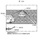
- FIG. 13A is an explanatory diagram of the side-based rear surface search procedure when part of the cut-in vehicle V2 is imaged
- FIG. 13B is a side-based rear surface search procedure when the entire cut-in vehicle V2 is imaged. It is an explanatory diagram. As shown in these figures, search is performed by changing the angle of the side line, assuming a slight deviation in the angle of the side line from the position that is perpendicular to the tilt of the side in the real space (on the bird's eye view). .
- a line scan is performed by changing the angle and the vertical position centering on the rear end position of the side surface of each figure, which is the starting point of the search start.
- a histogram is generated by accumulating vote values along lines in UD space. For this reason, the line drawn along the actual rear surface of the vehicle has the highest accumulated vote value, so the position of the rear surface of the vehicle body can be searched by specifying the line with the highest accumulated value from the histogram. Since there is a possibility that there is an error in the position of the rear end of the side surface, by searching by changing the position and angle based on this position, the error in the position of the rear end of the side surface itself is also absorbed, and the deviation in the angle of the side surface is corrected.
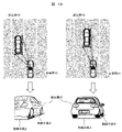
- the detection base line switching unit 74 determines whether the detection processing of the cut-in vehicle V2 reflected in the image is more stable when the detection process is performed on the back side basis or when the detection process is performed on the side basis. For more stable detection of the cut-in vehicle V2, it is better to use a longer line segment as the base line on the image. , the contour shape of the vehicle (length and position of the back and sides) can be stably detected. Therefore, the detection base line switching unit 74 determines which of the back surface and the side surface should be used as the base.
- the left diagram of FIG. 14 is shown.
- the right diagram of FIG. 14 is shown.
- the image captured by the stereo camera unit 1 shows the length of the side of the vehicle V2. longer than the length of the back. Therefore, it is considered that the contour detection of the cut-in vehicle V2 is stabilized if the side surface is used as the base.
- the upper right diagram of FIG. 14 shows the upper right diagram of FIG.
- the image captured by the stereo camera unit 1 shows that the length of the back of the cut-in vehicle V2 is longer than the length of the sides. Therefore, it is considered that contour detection of the cut-in vehicle V2 is stabilized if the back surface is used as a base.
- the detection base line switching unit 74 estimates the rough center of gravity position of the cutting-in vehicle V2 when only the back surface of the cutting-in vehicle V2 is identified or when only the side surface of the cutting-in vehicle V2 is identified.
- the position of the center of gravity may be estimated by using a standard vehicle size as a reference based on the extraction result of the side surface and the rear surface and their relative positions. It should be noted that here, since it is only a rough judgment as to which of the back and side surfaces should be used as the base to stabilize the overall processing, if the length of the back surface and the side surfaces are roughly the same, which one should be used as the base for the search? result does not change significantly.
- the contour detection performance deteriorates significantly when trying to extract the back surface based on the side surface when the side surface of the cut-in vehicle V2 is not clearly visible, as shown in FIG.
- the back surface is searched based on the result of unstable side extraction, it becomes difficult to finally obtain a stable contour shape (the length of the back surface and side surfaces).
- the side surface is extracted from the unstable back surface.
- the searched side surface tends to be unstable and unreliable.
- the detection base line switching unit 74 assumes that the cut-in vehicle V2 is about the size of a general passenger car, or that the cut-in vehicle V2 is running parallel to the own vehicle V0. After estimating the approximate center of gravity position of the cut-in vehicle V2 under each condition such as the back and side may be selected as the base line. Alternatively, the detection base line switching unit 74 may switch the base line of the detection process using the extracted length of the side surface or back surface and the angle between the center of gravity and the own vehicle V0.
- the detection base line switching unit 74 switches at a certain timing.
- the side-based detection process may be switched to the rear-side based detection process.
- the back-based side searching unit 75 searches for a line segment on the side in the UD space by utilizing the searched inner end position of the back.
- the angles in the UD space are centered on the position perpendicular to the inclination of the back of the cut-in vehicle V2 on the bird's-eye view, assuming a slight deviation in the angle of the back line. to explore the sides.
- the search is performed by changing the lateral position based on the inner edge position of the back surface.
- Line scanning is performed by changing the angle and the position centering on the inner edge of the back surface shown in the lower drawing of FIG.
- a histogram is generated by drawing a line and accumulating vote values on the line in the UD space. Therefore, since the accumulated value is the highest in the line drawn along the side of the vehicle where the voting value is high, the position of the side of the vehicle can be searched. Since the inner position of the back surface itself may have an error, searching by changing the position and angle absorbs the deviation of the inner position of the back surface and stably correctly searches for the side line segment in the UD space. becomes possible.
- ⁇ Detailed shape fitting part 76 Accurately estimating the rear angle position of the cut-in vehicle V2 is important for collision determination with the cut-in vehicle V2. This is because the collision or contact with the cutting-in vehicle V2 may occur at the back, rear corner, side, or front corner, but in terms of avoiding collision or contact with the rear, the rear-end collision with the preceding vehicle V1 should be avoided. While it can be dealt with with conventional technology to avoid collisions with rear corners, side faces, and front corners, avoiding collisions and contact with the rear corners, side faces, and front corners cannot be realized with the conventional technology. This is because accurately estimating the position is also effective for avoiding collisions and contact with the rear corners, side faces, and front corners of the cut-in vehicle V2.
- the rough position of the side surface can be estimated by any of the above methods, if the cut-in vehicle V2 has a design with rounded corners, or has a body shape or color tone that makes it difficult to calculate the parallax. For example, it is possible that the length of the lateral line segment (that is, the position of the anterior and posterior angles) cannot be accurately estimated. Therefore, in the detailed shape fitting unit 76, assuming that the cut-in vehicle V2 has a rectangular outline on the bird's-eye view, the outline frame of the vehicle is fitted, and the positions of the rear corners are also accurately extracted.
- FIG. 16 is a diagram illustrating an example of fitting procedures for the outline frame by the detailed shape fitting unit 76.
- FIG. 16A using the parallax of the side imaged by the stereo camera unit 1, the normal line at each point of the side surface is calculated, and the parallax on the back surface imaged by the stereo camera unit 1 is calculated. Use it to compute the normal at each point on the back face. As a result, many normal lines can be drawn on the side and rear surfaces of the cut-in vehicle V2.
- FIG. 16(b) a vertical line on the bird's eye view to the back normal and a vertical line on the bird's eye view to the side normal are calculated, and a pair of the side vertical line and the back vertical line is calculated.
- the process of FIG. 16(c) may be executed to accurately extract the position of the dorsal horn. That is, as shown in FIG. 16(c), a large number of normal lines obtained in FIG. Estimate the angle at which the rectangle best fits cut-in vehicle V2 by rotating the rectangle so that the sum of the distances that the rectangle intersects with the normal is the shortest (so that the sum of the squared errors is minimized). This allows accurate estimation of the trailing edge angle and the leading edge.
- ⁇ Feature point tracking/velocity estimation unit 77 With the detection processing thus far, it has become possible to estimate the contour shape (the length and position of the back and sides) of the cut-in vehicle V2. However, in a situation in which only a portion of the side or back of the cut-in vehicle V2 is captured in the image, the vehicle size increases as the cut-in vehicle V2 enters the screen after the contour shape fitting by the above method. Large and often detected. Therefore, the speed estimation method using the center of gravity or the speed estimation method assuming that the entire vehicle body is visible may result in a large error in the estimated speed of the cut-in vehicle V2.
- the feature point tracking/speed estimating unit 77 calculates feature points between consecutive imaging frames for the cut-in vehicle V2 in the rectangular parallelepiped corresponding to the rectangle fitted by the detailed shape fitting unit 76.
- Chase In particular, by preferentially using feature points that can be stably tracked across multiple frames, noise components that could be tracked only in one frame are removed, and feature points that can be tracked are also largely tracked.
- the speed of the cut-in vehicle V2 is calculated by using only the feature points that have been stably tracked while removing the moving distance that is out of range as a noise component.
- FIG. lateral direction Since the contour shape of the vehicle and the three-dimensional positions of the feature points can be measured from the parallax image of the stereo camera unit 1, FIG. lateral direction) is represented by a velocity vector. Since a plurality of feature points are calculated in this way, a plurality of velocity vectors are calculated with respective positions on the surface of the contour of the vehicle body as origins. Assuming a rigid car body, even if the origin is different in 3D space, it will have the same speed in the same direction. A stable velocity vector is calculated by using the average value.
- the background and white lines in the image are similarly tracked for feature points to calculate the velocity vector, and it is possible to determine whether the cut-in vehicle V2 is approaching the white line or straddling the white line. Regardless of the behavior of V0, it is a relative velocity vector necessary for determining whether the vehicle V2 is at risk of collision or contact with the vehicle V0, such as whether the other vehicle is approaching the vehicle itself. , absolute velocity vector (in what direction it is moving relative to a stationary object), position in the lane, etc.
- ⁇ Vehicle identification unit 78 When the velocity vector estimation by the feature point tracking/velocity estimating unit 77 is completed, it can be determined whether the solid object candidate has a rectangular parallelepiped shape and whether it is approaching the own vehicle V0. It can be identified as the cut-in vehicle V2. However, in order to further improve the detection accuracy of the interrupting vehicle V2, the vehicle identification unit 78 determines whether the interrupting vehicle V2 is a four-wheeled vehicle or a two-wheeled vehicle based on information such as the back width and side length of the interrupting vehicle V2.
- stationary objects can be erroneously detected as cut-in candidates in environments where errors are likely to occur in the behavior of the own vehicle and the movements of other vehicle candidates, such as when the own vehicle V0 is approaching a wall while traveling on a curve. is suppressed.
- the cut-in vehicle determination unit 8 utilizes the information obtained by the rectangular shape fitting unit 7 in chronological order to comprehensively determine whether or not the own vehicle V0 is the cut-in vehicle V2 to be controlled. judge.
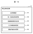
- the interrupting vehicle determination unit 8 includes a white line information unit 81, a same lane merging determination unit 82, a crowded complex environment determination unit 83, a preceding vehicle candidate determination unit 84, and a contact possibility determination unit 84, which are shown in FIG. It has a determination unit 85 . Each part will be described in order below.
- the white line information unit 81 observes the result of white line recognition as one piece of information for comprehensive determination. Specifically, the white line information unit 81 grasps the left and right white lines of the lane in which the vehicle V0 is traveling, and also grasps whether the behavior of the vehicle within the left and right white lines is stable. In addition, when there is a vehicle running side by side, it is also determined whether the vehicle running side by side is traveling within the white line while observing the traffic rules. Then, when both the own vehicle and the other vehicle are traveling stably within the white line, the same lane merging determination unit 82 is enabled. On the other hand, if not, the congestion complex environment determination unit 83 is enabled.
- the same-lane merging determination unit 82 uses the position and presence/absence of a white line to determine whether to cut into the lane in which the host vehicle V0 is traveling. This same-lane merging determination unit 82 detects a vehicle that has a high possibility of cutting into the white line of the vehicle traveling, that is already slightly approaching across the white line, or a vehicle that has a high possibility of contact within a predetermined time. Extract it as a cut-in vehicle candidate. Conversely, with respect to vehicles that do not cross the white line, it is determined that there is no intention to cut in even if the vehicle is approaching V0 to some extent. However, when the lateral position of the own vehicle or the other vehicle within the white line is rapidly changing, the possibility of contact may be determined based on the degree of change, even if the vehicle does not deviate from the oblique line.
- the crowded and complicated environment judgment unit 83 judges that the driving environment is such that the vehicle does not comply with the rules, such as driving within the white line, and the white line is blurred or does not exist in the first place, and there is a result of white line recognition. Do not use this as This is because there is no point in using the recognition result of the white line if neither the other vehicle nor the own vehicle V0 adheres to traveling within the white line. In such a driving environment, it is basically determined whether or not control should be performed based on the behavior of the own vehicle V0 and the behavior of the opponent vehicle.
- the preceding vehicle candidate determination unit 84 determines whether or not a nearby vehicle can be a candidate for the preceding vehicle V1 to be followed when the host vehicle V0 performs the preceding vehicle following control (ACC).
- the vehicle is set as a candidate for the preceding vehicle V1.
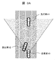
- FIGS. 3A and 3B when the own vehicle V0 is automatically following the preceding vehicle V1, when an interrupting vehicle V2, which is slower than the preceding vehicle V1, cuts into the course of the own vehicle, It is important to quickly switch the vehicle to be followed from the preceding vehicle V1 to the interrupting vehicle V2 in order to continue safe preceding vehicle following control.
- the preceding vehicle candidate determination unit 84 determines that the preceding vehicle candidate will cross the white line and cut into the own lane. Conversely, if it is determined that the driving area does not require the adherence to the white line driving, the condition is not used.
- the contact possibility determination unit 85 performs contact determination using the contour shapes of the host vehicle V0 and the other vehicle.
- the contact possibility determination unit 85 of the present embodiment accurately estimates the contour shape of the other vehicle, uses this contour shape, assumes that the shape of the own vehicle V0 is known, and performs contact determination between the contour shapes. do. Then, in areas where the rule of traveling within the white lines is observed, warnings and controls are early implemented for vehicles that have cut in the white lines and are approaching.
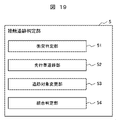
- the contact tracing determination unit 5 performs warning and control determination for contact, collision, etc. with the own vehicle V0 for an object that is identified as a vehicle and whose position and speed change as a vehicle. In addition, it is used as a tracked object while the preceding vehicle automatic follow-up ACC is being used. In order to execute this processing, the contact tracing determination unit 5 has a collision determination unit 51, a preceding vehicle tracking unit 52, a tracked object change unit 53, and an integrated determination unit 54 shown in FIG. Each part will be described in order below.
- the bird's-eye view of FIG. 20 shows a situation in which a preceding vehicle V1 and own vehicle V0 are present in the same lane.
- the collision determination unit 51 and the preceding vehicle tracking unit 52 will be described with reference to this figure. If the preceding vehicle V1 in FIG. 20 is slower than the own vehicle V0 or is stopped, there is a possibility that the own vehicle V0 will collide with the preceding vehicle V1. If the distance between the preceding vehicle V1 and the own vehicle V0 is sufficiently far, the driver can apply the brakes to decelerate or stop the vehicle. As a rear-end collision preventive measure, a warning is sufficient, and emergency braking is not necessary. .
- the collision determination unit 51 uses relative speed and distance from the position and speed of the vehicle recognized by the preceding vehicle identification unit 4 to determine after how many seconds the vehicle will come into contact with V0. If it is possible to avoid a rear-end collision by stepping on , it will decide to issue a warning.
- the distance between the preceding vehicle V1 and the own vehicle V0 is kept within a certain distance set by the driver and less than the upper limit speed. Based on the relative speed and distance of V0, control amounts such as acceleration and braking of the own vehicle V0 are determined so that the vehicle V0 can smoothly follow the preceding vehicle V1.
- the tracking object changing unit 53 changes the tracking object. Determine the timing to change the vehicle.
- a method of detecting a cut-in vehicle based on the side surface starting from the side surface extraction unit 6 is used to stably detect the vehicle body contour and estimate the speed of a vehicle whose side surface looks large. Based on the information obtained from these, the judgment result of the cut-in vehicle judgment unit 8 is used to determine the warning timing and control details in the integrated judgment unit 54 including emergency braking and avoidance by the cut-in vehicle V2 in a short distance. to decide.
- the integrated judgment unit 54 based on the obtained information, when the driver permits the control to avoid the inside of the lane or the road, it is determined whether the control should be performed only by stepping on the brake. An integrated judgment may be made as to whether avoidance and brake control while steering are appropriate, based on the availability of objects or the availability of three-dimensional objects on the road including up to the road shoulder. In addition to avoiding inside the white line, if the road shoulder can be detected and the entire circumference of the vehicle can be sensed, the integrated determination unit also performs evacuation to the road shoulder. If there is a vehicle in front of your vehicle V0 that is slightly ahead diagonally and there are no other vehicles running in the surroundings, avoidance steering is determined while crossing the white line on the left side, and the left lane is used. Evacuation is carried out by simultaneously sensing running vehicles and road shoulders.
- ⁇ Vehicle control unit 9 In the vehicle control unit 9, sound, vehicle speed control, emergency braking, steering, etc. are carried out according to the warning and control details determined above.
- FIG. 21 Processing flow> A processing procedure performed by the external world recognition device 100 configured as described above will be described below with reference to the flowchart of FIG. 21 .
- step S1 the left and right cameras of the stereo camera unit 1 capture a left image PL and a right image PR in front of the own vehicle V0 (see FIG. 3B).
- step S2 the image processing unit of the stereo camera unit 1 performs stereo matching after parallelizing the left and right images and performing sensitivity correction, and generates parallax images.
- step S3 the parallax voting unit 2 uses the parallax image obtained in step S2 to vote the parallax value D in the UD space (see FIG. 4).
- this parallax value voting when there is parallax such that the depth is the same and the abscissa on the image is the same, that is, when there is a three-dimensional object standing vertically on the road surface reflected in the image, the parallax vote is performed in the UD space. It will be a mechanism that makes it easy to gather in the same place. In other words, by using this UD space, the parallax vote value is accumulated at the location where the three-dimensional object exists. Therefore, by searching for a place with a high vote value in the UD space, the existence of the three-dimensional object can be found. The surrounding environment is sensed while using this UD space.
- step S4 the back surface extraction unit 3 scans the UD space in the horizontal direction to search for solid object candidates in order to extract the back surface of the solid object using the result of voting in the UD space (see FIG. 5A). ). Since it searches in the horizontal direction, it is possible to stably detect a three-dimensional object whose back surface extends in the horizontal direction as viewed from the camera. In particular, with respect to the rear surface of the vehicle, since the vehicles are often oriented basically in the same direction, it is basically possible to detect the rear surface of the vehicle by this processing, and the direction to the preceding vehicle V1 can be detected. The candidate for the back surface of the vehicle extracted by this process is used for emergency braking and following the preceding vehicle V1. Three-dimensional objects such as two-wheeled vehicles, pedestrians, and utility poles are also subject to extraction in this process. As for a running object such as a car, the process up to its type identification process is performed.
- step S5 the preceding vehicle identification unit 4 performs identification processing on three-dimensional object candidates within the assumed width of the vehicle from among the three-dimensional object candidates extracted in step S4, and identifies whether they are vehicles. Furthermore, when the lane recognition result is obtained, this result is also used to determine whether the vehicle is in the adjacent lane or the preceding vehicle V1. Furthermore, it is determined at the same time whether or not an object within the assumed width of a two-wheeled vehicle is a two-wheeled vehicle from among the three-dimensional object candidates. In the same way, pedestrians are also examined, and reliability is improved by identifying the types of moving objects that are concerned about collisions and contact during vehicle driving.
- the conventional three-dimensional object detection and vehicle detection by the above steps S4 and S5 are basically a method of searching for a wall facing the own vehicle V0, and the processing is simplified by capturing the three-dimensional object. is.
- This method itself was a very efficient method for catching a three-dimensional object existing on the course R0 of the own vehicle and applying an emergency brake, or from the viewpoint of following the preceding vehicle V1.
- it has the disadvantage that it is not sufficient to deal with walls that come into contact with the side of the own vehicle V0, the side of the cut-in vehicle, and the like, and it is difficult to accurately grasp the tilt and position of a three-dimensional object.
- step S4 and S5 for searching the rear surface, it is difficult to handle the contact determination with the interrupting vehicle V2, and the switching determination of the preceding vehicle following object at the time of interruption is performed. , the following steps S6 to S8 are executed in parallel with the above steps S4 and S5.
- step S6 the side extraction unit 6 performs a side search and extracts the side of the cut-in vehicle V2 (see FIGS. 8 and 9). Furthermore, in this step, the cut-in vehicle V2 is the search target, so the side face extracting unit 6 determines whether there is a three-dimensional object with a certain height and a depth longer than a certain amount, It is determined whether or not the vehicle is a candidate for the cut-in vehicle.
- step S7 the right-angled shape fitting unit 7, if the cut-in vehicle candidate is actually the cut-in vehicle V2, utilizes the fact that a back line segment exists at right angles to the side line segment to determine the side line segment.
- a more stable right-angled shape is searched for by performing re-fitting processing (see FIGS. 11 and 12) of the leading and trailing end positions of , and further performing back face search processing (see FIGS. 13A and 13B).
- the speed of the vehicle is further improved by searching the image for the movement of feature points within the contour (see FIG. 17). This is particularly necessary when there is a difference in resolution between the parallax image and the original image.
- Image information processed for post-processing such as a parallax image, often has a lower resolution than the original image. Therefore, if the original image with high resolution is used for speed calculation, accuracy is high. Therefore, by using the original image and calculating the flow within the extracted contour shape, the relative velocity is calculated. Simultaneously calculate the velocity. Furthermore, by calculating the speed of the stationary object in the same manner for the background, the moving speed of the cut-in vehicle V2 with respect to the stationary object (the absolute speed is also calculated).
- step S8 the cut-in vehicle determination unit 8 uses the relative position, speed, absolute position, speed, white line position, vehicle behavior, etc. of the cut-in vehicle candidate to influence the driving of the vehicle V0. It is determined whether or not the interrupt vehicle V2 is exerting an effect. If there is a possibility of contact, depending on the angle of contact, considering the contour shapes of each other, it is better for the own vehicle V0 to perform emergency braking, or to avoid the lane by steering, or to the road shoulder. It judges whether avoidance candidates including Also, if the vehicle is following the preceding vehicle, even if there is no risk of contact or collision, it is determined at what timing to switch the target vehicle for following.
- step S9 the contact tracing determination unit 5 determines collision or contact with the own vehicle V0 using the preceding vehicle identification information, the own vehicle behavior, and the information of the vehicle judged to be the interrupting vehicle V2. .
- the contour information of the own vehicle V0 and the contour information of other vehicles while considering the behavior of the own vehicle, it is possible to accurately judge contact accidents including collisions in addition to frontal collisions and collisions between the vehicle body angle and the side. enable In addition, it is possible to suppress false alarms and false controls.
- step S10 the vehicle control unit 9 performs warning and control, or switches the target of the following vehicle based on the determination result of step S9.
- the cutting-in vehicle is detected based on the side information of the cutting-in vehicle. It can be recognized as a vehicle. If there is a possibility of contact with the interrupting vehicle, the own vehicle is braked, and if there is no possibility of contact, the vehicle to be followed in the preceding vehicle tracking control is switched from the previous preceding vehicle to the interrupting vehicle for stability. You can continue running.
- Detection base line switching section 75 Back face-based side searching section 76... Detailed shape fitting section 77... Feature point tracking/velocity estimating section 78... Vehicle identification unit 8... Interrupting vehicle determination unit 81... White line information unit 82... Same lane merging determination unit 83... Congested complicated environment determination unit 84... Leading vehicle candidate determination unit 85... Contact possibility determination unit 9... Vehicle control unit, V0... Own vehicle, V1... Preceding vehicle, V2... Interrupting vehicle
Landscapes
- Engineering & Computer Science (AREA)
- Physics & Mathematics (AREA)
- General Physics & Mathematics (AREA)
- Theoretical Computer Science (AREA)
- Automation & Control Theory (AREA)
- Transportation (AREA)
- Mechanical Engineering (AREA)
- Computer Vision & Pattern Recognition (AREA)
- Multimedia (AREA)
- Image Analysis (AREA)
- Traffic Control Systems (AREA)
- Image Processing (AREA)
Priority Applications (2)
| Application Number | Priority Date | Filing Date | Title |
|---|---|---|---|
| DE112022002244.2T DE112022002244T5 (de) | 2021-06-24 | 2022-02-07 | Aussenumgebungs-erkennungsvorrichtung und aussenumgebungs-erkennungsverfahren |
| JP2023529475A JP7602636B2 (ja) | 2021-06-24 | 2022-02-07 | 外界認識装置、および、外界認識方法 |
Applications Claiming Priority (2)
| Application Number | Priority Date | Filing Date | Title |
|---|---|---|---|
| JP2021-104736 | 2021-06-24 | ||
| JP2021104736 | 2021-06-24 |
Publications (1)
| Publication Number | Publication Date |
|---|---|
| WO2022269980A1 true WO2022269980A1 (ja) | 2022-12-29 |
Family
ID=84544019
Family Applications (1)
| Application Number | Title | Priority Date | Filing Date |
|---|---|---|---|
| PCT/JP2022/004712 Ceased WO2022269980A1 (ja) | 2021-06-24 | 2022-02-07 | 外界認識装置、および、外界認識方法 |
Country Status (3)
| Country | Link |
|---|---|
| JP (1) | JP7602636B2 (https=) |
| DE (1) | DE112022002244T5 (https=) |
| WO (1) | WO2022269980A1 (https=) |
Citations (3)
| Publication number | Priority date | Publication date | Assignee | Title |
|---|---|---|---|---|
| JP2008117073A (ja) * | 2006-11-01 | 2008-05-22 | Fuji Heavy Ind Ltd | 割り込み車両検出装置 |
| WO2017047687A1 (ja) * | 2015-09-17 | 2017-03-23 | 株式会社日立国際電気 | 監視システム |
| JP2020173799A (ja) * | 2019-04-09 | 2020-10-22 | センスタイム グループ リミテッド | 対象の三次元検出およびインテリジェント運転制御方法、装置、媒体および機器 |
Family Cites Families (1)
| Publication number | Priority date | Publication date | Assignee | Title |
|---|---|---|---|---|
| JP7075833B2 (ja) | 2018-06-27 | 2022-05-26 | 日産自動車株式会社 | 物体検出方法及び物体検出装置 |
-
2022
- 2022-02-07 WO PCT/JP2022/004712 patent/WO2022269980A1/ja not_active Ceased
- 2022-02-07 JP JP2023529475A patent/JP7602636B2/ja active Active
- 2022-02-07 DE DE112022002244.2T patent/DE112022002244T5/de active Pending
Patent Citations (3)
| Publication number | Priority date | Publication date | Assignee | Title |
|---|---|---|---|---|
| JP2008117073A (ja) * | 2006-11-01 | 2008-05-22 | Fuji Heavy Ind Ltd | 割り込み車両検出装置 |
| WO2017047687A1 (ja) * | 2015-09-17 | 2017-03-23 | 株式会社日立国際電気 | 監視システム |
| JP2020173799A (ja) * | 2019-04-09 | 2020-10-22 | センスタイム グループ リミテッド | 対象の三次元検出およびインテリジェント運転制御方法、装置、媒体および機器 |
Also Published As
| Publication number | Publication date |
|---|---|
| DE112022002244T5 (de) | 2024-02-22 |
| JP7602636B2 (ja) | 2024-12-18 |
| JPWO2022269980A1 (https=) | 2022-12-29 |
Similar Documents
| Publication | Publication Date | Title |
|---|---|---|
| US10685449B2 (en) | Surrounding environment recognition device for moving body | |
| JP7025912B2 (ja) | 車載環境認識装置 | |
| US10627228B2 (en) | Object detection device | |
| CN106663374B (zh) | 信号机检测装置以及信号机检测方法 | |
| JP4517972B2 (ja) | 障害物判断装置及び方法 | |
| US9121717B1 (en) | Collision avoidance for vehicle control | |
| JP5904286B2 (ja) | 運転支援装置 | |
| US10871565B2 (en) | Object detection apparatus and object detection method | |
| US20160107643A1 (en) | Object recognition apparatus | |
| CN202169907U (zh) | 车外环境识别装置 | |
| CN107408345A (zh) | 物标存在判定方法以及装置 | |
| JP2018097582A (ja) | 運転支援装置、及び運転支援方法 | |
| JP2017117345A (ja) | 運転支援装置及び運転支援方法 | |
| JP2017037473A (ja) | 操舵支援装置 | |
| KR102304851B1 (ko) | Ecu, 상기 ecu를 포함하는 무인 자율 주행 차량, 및 이의 주변 차량 인지 방법 | |
| JP2017187864A (ja) | 車両制御装置、車両制御方法 | |
| JP2019046143A (ja) | 走行支援装置 | |
| JP2012088217A (ja) | 運転支援制御装置 | |
| KR101103526B1 (ko) | 스테레오 카메라를 이용한 충돌회피 방법 | |
| JP2018097689A (ja) | 車両制御装置、車両制御方法 | |
| JP2006004188A (ja) | 障害物認識方法及び障害物認識装置 | |
| CN108885837A (zh) | 移动轨迹检测装置、移动物体检测装置、移动轨迹检测方法 | |
| KR102485318B1 (ko) | 단안 영상 기반 추월 및 합류 차량 인식 시스템 및 방법 | |
| JP2001082954A (ja) | 画像処理装置及び画像処理測距方法 | |
| JP7602636B2 (ja) | 外界認識装置、および、外界認識方法 |
Legal Events
| Date | Code | Title | Description |
|---|---|---|---|
| 121 | Ep: the epo has been informed by wipo that ep was designated in this application |
Ref document number: 22827904 Country of ref document: EP Kind code of ref document: A1 |
|
| WWE | Wipo information: entry into national phase |
Ref document number: 2023529475 Country of ref document: JP |
|
| WWE | Wipo information: entry into national phase |
Ref document number: 112022002244 Country of ref document: DE |
|
| 122 | Ep: pct application non-entry in european phase |
Ref document number: 22827904 Country of ref document: EP Kind code of ref document: A1 |