WO2022269869A1 - 情報処理装置、情報処理システム、情報処理方法、及び情報処理プログラム - Google Patents
情報処理装置、情報処理システム、情報処理方法、及び情報処理プログラム Download PDFInfo
- Publication number
- WO2022269869A1 WO2022269869A1 PCT/JP2021/023974 JP2021023974W WO2022269869A1 WO 2022269869 A1 WO2022269869 A1 WO 2022269869A1 JP 2021023974 W JP2021023974 W JP 2021023974W WO 2022269869 A1 WO2022269869 A1 WO 2022269869A1
- Authority
- WO
- WIPO (PCT)
- Prior art keywords
- rule
- information
- information processing
- device operation
- terminal
- Prior art date
- Legal status (The legal status is an assumption and is not a legal conclusion. Google has not performed a legal analysis and makes no representation as to the accuracy of the status listed.)
- Ceased
Links
Images






Classifications
-
- G—PHYSICS
- G06—COMPUTING OR CALCULATING; COUNTING
- G06N—COMPUTING ARRANGEMENTS BASED ON SPECIFIC COMPUTATIONAL MODELS
- G06N20/00—Machine learning
-
- H—ELECTRICITY
- H04—ELECTRIC COMMUNICATION TECHNIQUE
- H04L—TRANSMISSION OF DIGITAL INFORMATION, e.g. TELEGRAPHIC COMMUNICATION
- H04L41/00—Arrangements for maintenance, administration or management of data switching networks, e.g. of packet switching networks
- H04L41/16—Arrangements for maintenance, administration or management of data switching networks, e.g. of packet switching networks using machine learning or artificial intelligence
-
- G—PHYSICS
- G06—COMPUTING OR CALCULATING; COUNTING
- G06F—ELECTRIC DIGITAL DATA PROCESSING
- G06F13/00—Interconnection of, or transfer of information or other signals between, memories, input/output devices or central processing units
-
- G—PHYSICS
- G06—COMPUTING OR CALCULATING; COUNTING
- G06N—COMPUTING ARRANGEMENTS BASED ON SPECIFIC COMPUTATIONAL MODELS
- G06N5/00—Computing arrangements using knowledge-based models
- G06N5/02—Knowledge representation; Symbolic representation
-
- G—PHYSICS
- G06—COMPUTING OR CALCULATING; COUNTING
- G06N—COMPUTING ARRANGEMENTS BASED ON SPECIFIC COMPUTATIONAL MODELS
- G06N5/00—Computing arrangements using knowledge-based models
- G06N5/04—Inference or reasoning models
-
- H—ELECTRICITY
- H04—ELECTRIC COMMUNICATION TECHNIQUE
- H04L—TRANSMISSION OF DIGITAL INFORMATION, e.g. TELEGRAPHIC COMMUNICATION
- H04L12/00—Data switching networks
- H04L12/28—Data switching networks characterised by path configuration, e.g. LAN [Local Area Networks] or WAN [Wide Area Networks]
-
- G—PHYSICS
- G06—COMPUTING OR CALCULATING; COUNTING
- G06F—ELECTRIC DIGITAL DATA PROCESSING
- G06F3/00—Input arrangements for transferring data to be processed into a form capable of being handled by the computer; Output arrangements for transferring data from processing unit to output unit, e.g. interface arrangements
- G06F3/01—Input arrangements or combined input and output arrangements for interaction between user and computer
- G06F3/048—Interaction techniques based on graphical user interfaces [GUI]
- G06F3/0484—Interaction techniques based on graphical user interfaces [GUI] for the control of specific functions or operations, e.g. selecting or manipulating an object, an image or a displayed text element, setting a parameter value or selecting a range
Definitions
- the present disclosure relates to an information processing device, an information processing system, an information processing method, and an information processing program.
- Japanese Patent Application Laid-Open No. 2002-200003 manages a rule that specifies that an action execution server that provides an action execution service executes a given action triggered by the provision of predetermined information from an information provision server that provides an information provision service.
- a collaboration server which is a device that This cooperation server changes a rule that is not subject to the change instruction (that is, another rule) that can be changed in the same way as the rule that is the subject of the change instruction, along with the rule that is the subject of the change instruction, in accordance with the change instruction.
- JP 2017-102643 A (for example, claim 1, paragraph 0022)
- the above device does not perform processing for estimating rules from information indicating the user's device operation.
- the user has to manually create a change instruction for the target rule, so there is a problem that the rule cannot be changed easily.
- An object of the present disclosure is to provide an information processing device, an information processing system, an information processing method, and an information processing program that make it possible to easily change rules for coordinating the operations of devices.
- An information processing device includes a communication unit that communicates with an external device including a terminal, a rule management unit that manages rules regarding cooperation between a plurality of devices, a notification management unit, and a device management unit.
- the rule management unit acquires device operation information indicating a user operation on a first device among the plurality of devices, and controls a cooperative device of a second device among the plurality of devices based on the device operation information.
- Estimates the rule including a trigger condition that is a condition for starting an operation
- the notification management unit notifies the terminal of an inquiry including the estimated rule via the communication unit, and sends the inquiry from the terminal to the Obtaining an answer as to whether or not to register the rule
- the rule management unit registers the rule if the answer indicates approval of registration of the rule
- the device management unit registers the registered rule.
- the linked device operation is executed based on the rule when the device operation information that satisfies the included trigger condition is input to the first device.
- An information processing method is a method implemented by an information processing device that communicates with an external device including a terminal and manages rules regarding cooperation between a plurality of devices, wherein a first out of the plurality of devices Acquiring device operation information indicating a user operation on a device, and creating the rule including a trigger condition that is a condition for starting a linked device operation of a second device among the plurality of devices based on the device operation information. informing the terminal of an inquiry including the inferred rule, obtaining an answer from the terminal as to whether or not to register the rule, the answer indicating approval of registration of the rule. registering the rule; and when the device operation information satisfying the trigger condition included in the registered rule is input to the first device, the linked device is operated based on the rule. and executing.
- FIG. 1 is a diagram showing an overview of an information processing system according to Embodiment 1;
- FIG. 2 is a diagram showing an outline of rule estimation and rule registration executed by the information processing system shown in FIG. 1;
- FIG. FIG. 2 is a diagram showing an outline of discarding of rules executed by the information processing system shown in FIG. 1;
- 2 is a block diagram showing an example of the configuration of the information processing device and terminal shown in FIG. 1;
- FIG. 5 is a diagram showing a data structure and a specific example of device management information stored in a device management information storage unit of a device management unit of the information processing apparatus shown in FIG. 4;
- FIG. (A) and (B) are diagrams showing examples of display of inquiry information on a terminal.
- FIG. 5 is a block diagram showing an example of the hardware configuration of the information processing apparatus shown in FIGS. 1 and 4;
- FIG. FIG. 5 is a block diagram showing an example of the hardware configuration of the terminal shown in FIGS. 1 and 4;
- FIG. 7 is a flow chart showing an example of processing for registering a rule executed by the information processing system according to the first embodiment;
- 7 is a flowchart showing an example of processing for discarding a rule executed by the information processing system according to Embodiment 1;
- FIG. 10 is a diagram showing an outline of an information processing system according to Embodiment 2;
- FIG. 12 is a diagram showing an overview of rule estimation and rule registration executed by the information processing system shown in FIG. 11;
- FIG. 12 is a block diagram showing an example of the configuration of the information processing device and terminal shown in FIG. 11;
- FIG. 14 is a diagram showing a data structure and a specific example of sensor management information stored in a sensor management information storage unit of the sensor management unit of the information processing apparatus shown in FIG. 13;
- FIG. FIG. 11 is a flow chart showing an example of processing for registering a rule executed by the information processing system according to the second embodiment;
- FIG. 1 is a diagram showing an outline of an information processing system 3 according to Embodiment 1.
- the information processing system 3 is a system that provides device operations.
- the information processing system 3 performs device operations based on rules relating to cooperation of a plurality of devices.
- a rule includes a set of operating procedures and trigger conditions for operating the device. That is, in the information processing system 3, when the user performs an operation that satisfies a trigger condition on a device (for example, the target device ND1), the information processing device 1 operates the remaining devices (for example, the target device) based on the rule.
- the device operation of ND2) which is a linked device different from that of ND2), is executed.
- the trigger condition is a condition related to the operation of the target device, and when the device operation information D1 indicating the operation of the target device satisfies the trigger condition, the linked device cooperating with this target device operates based on the linked device operation information D2. Automatically perform the action specified in the rule.
- the information processing system 3 can provide equipment operation services that combine various equipment operations.
- the information processing system 3 includes an information processing device 1 that provides device management, rule management, and notification management, and a terminal 2 that is an inquiry destination when the information processing device 1 makes an inquiry about the status of rules.
- the information processing device 1 is, for example, a computer.
- the terminal 2 is, for example, a terminal device such as a smart phone, a tablet terminal, or a personal computer (PC).
- the plurality of devices includes a device ND1 that transmits device operation information D1 to the information processing device 1, and a device ND2 that performs an operation based on the linked device operation information D2 received from the information processing device 1.
- the device ND1 may be one device, or a plurality of devices ND1_1, ND1_2, . . . , ND1_m (where m is a positive integer).
- the device ND2 may be one device, or may be a plurality of devices ND2_1, ND2_2, . . . , ND2_n (where n is a positive integer).
- the device ND1 and the device ND2 are examples of household electrical devices, for example, and are also denoted as device ND. Note that the device ND may be an electrical device other than a household electrical device.
- the device ND1 When the device ND1 is operated by the user, the device ND1 transmits device operation information D1 to the information processing device 1. Then, the information processing apparatus 1 transmits the linked device operation information to the device ND2 and executes the device operation of the device ND2. That is, when the user operates the device ND1, the device operation of the device ND2 is automatically performed by the information processing apparatus 1, and the device ND2 performs an operation based on the received linked device operation information D2.
- the device ND has one or both of a function of transmitting the device operation information D1 to the information processing device 1 and a function of executing an operation based on the linked device operation information D2 received from the information processing device 1 .
- the device ND1 has a function of transmitting device operation information D1 to the information processing apparatus 1
- the device ND2 has a function of executing an operation based on the received linked device operation information D2.
- the information processing device 1 manages rules regarding cooperation between multiple devices ND.
- the information processing apparatus 1 acquires device operation information D1 indicating a user operation on a device (also referred to as a "first device") ND1 among the plurality of devices ND, and based on the device operation information D1, controls the plurality of devices ND.
- a rule including a trigger condition which is a condition for starting the operation of the linked device of the device (also referred to as “second device”) ND2, is estimated.
- the information processing device 1 notifies the terminal 2 of an inquiry I1 including the estimated rule, and obtains from the terminal 2 an answer I2 as to whether or not to register the rule.
- the information processing device 1 registers the rule when the reply I2 indicates approval of rule registration.
- device operation information D1 that satisfies a trigger condition included in a registered rule is input to the device ND1, the information processing apparatus 1 executes a linked device operation based on the corresponding rule.
- the user possesses the terminal 2, and the information processing device 1 notifies the user of the rule (including the trigger condition of this rule) through the terminal 2.
- the information processing apparatus 1 acquires the device operation information D1 from the device ND1, the information processing apparatus 1 estimates rules (including trigger conditions) based on the device operation information D1.
- the information processing device 1 notifies the user's terminal 2 of an inquiry I1 about the rule (including the trigger condition).
- the information processing device 1 responds to the rule (including the trigger conditions). including conditions).
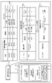
- FIG. 2 is a diagram showing an overview of rule estimation and rule registration executed by the information processing system 3 shown in FIG. First, management of registered rules will be described.
- the information processing device 1 stores and manages the rule management information 104a in a storage device (for example, the rule management information storage unit 104 in FIG. 3, which will be described later).
- the rule management information 104a is a rule created by the information processing device 1 and is stored in a storage device within the information processing device 1 or an external storage device that can communicate with the information processing device 1 .
- the rule management information 104a is desirably created for each user. That is, the rule management information 104a may be multiple pieces of information.
- a plurality of pieces of rule management information 104a are associated with a plurality of user IDs for identifying a plurality of users.
- the rule management information 104a shown in FIG. 2 is a database that manages a rule ID that is identification information of a rule, information indicating the registration date and time of the rule, and a series of device operation procedures in association with each other.
- the device operation procedure includes a device ID for identifying the device, property information, and whether or not the device operation procedure is the trigger condition (indicated by a circle "O"). (indicated by "-")).
- FIG. 2 shows D001 and D002 as specific examples of the device ND indicated by the device ID. In subsequent description, D001 shows a bathroom light and D002 shows a bathroom heating. However, the example of the device ND is not limited to bathroom lamps and bathroom heaters, and may be other electric devices.
- the information processing device 1 can perform device operations according to the rules registered as the rule management information 104a.
- the device operating procedure of the trigger condition is that the operating state of the bathroom light, which is the device of D001, is True (that is, the power is on).
- the operating state of the bathroom heater which is the device of D002
- the operation state of the bathroom heater (D002), which is one of the devices ND, can be set to True (that is, the power is turned on).
- the device operation information of the device ND is accumulated as the device operation information 123a.
- the device operation information 123a shown in FIG. 2 includes time indicating time information, device operation information ID indicating identification information of the device operation information, device ID indicating device identification information, and property information.
- the device operation information of the device ND indicated by the device operation information ID shown in FIG. and device operation information indicating that the operating state of bathroom heating is True (that is, the power is on), which occurred at 19:00:06 by DE002.
- the accumulated device operation information 123a is not limited to that shown in FIG. 2, and may be other information.
- the information processing device 1 estimates the rule by referring to the device operation information 123a.
- the information processing apparatus 1 determines that the device operation indicated by DE001 (that is, , power-on operation of the bathroom light), and the rule R001, which is the device operation indicated by DE002 (that is, operation of power-on of the bathroom heater).
- the rule estimation executed by the information processing device 1 is not limited to the example shown in FIG.
- the information processing device 1 transmits a notification of the rule (including the trigger condition) to the terminal 2 .
- the terminal 2 displays the information of the rule R001 as text on the display unit 23 such as a touch panel.
- the terminal 2 displays on the display unit 23 an inquiry (that is, a question sentence) "Would you like to register the rule?" to ask whether to register the rule R001.
- the user transmits an answer I2 as to whether or not to register the rule (including the trigger condition) by operating one of the "Yes" and "No” buttons displayed on the display unit 23 of the terminal 2. can do.
- the content displayed on the display unit 23 of the terminal 2 is not limited to the example shown in FIG.
- the information processing device 1 registers the rule in the rule management information storage unit 104 as the rule management information 104a when the registration of the rule is approved by the notification made by the terminal 2.
- the information processing apparatus 1 registers the rule R001 when the user presses the "yes" button on the terminal 2.
- FIG. 1 the user can use the information processing apparatus 1 to estimate the rule for operating the linked device from the device operation information D1 generated in daily life, and register the rule when the user's approval is obtained. can be done.
- the information processing system 3 determines whether or not to cancel the registration of the rule.
- the terminal 2 receives an answer I2 indicating that the rule is to be discarded, the rule is discarded.
- FIG. 3 is a diagram showing an overview of rule discarding executed by the information processing system 3 shown in FIG.
- components having the same functions as the components described in FIG. 2 are assigned the same reference numerals as those shown in FIG.
- DE011 generated at 19:00:03 is the device operation information indicating that the operating state of the bathroom light is True (that is, the power is on), and DE012 generated at 19:00:06.
- the operation state of bathroom heating is True (that is, the power is on), and DE013 indicates the device operation information that the bathroom heating is powered off at 19:00:06.
- the information processing device 1 when the information processing device 1 acquires the device operation information corresponding to the existing trigger condition, the information processing device 1 performs the remaining device operations of the rule.
- the operation state of D001 is set to True (that is, the power is turned on), and after the operation state of D002 is set to True (that is, the power is turned on), the user manually turns on the bathroom heating.
- the information processing device 1 instructs the terminal 2 to Notify about rule revocation.
- This notification allows the user to recognize that the rule is unnecessary and to select whether to discard the rule.
- whether or not to discard the rule R001 is checked by pressing a "Yes” or “No” button to answer the question "Are you sure you want to discard the rule?".
- the information processing device 1 discards the rule in the rule management information 104a when the discarding of the rule is approved by the reply sent from the terminal 2.
- the information processing device 1 discards the rule R001.
- the information processing apparatus 1 determines whether to cancel a rule based on device operation information that occurs in the user's daily life, and discards a rule that has been approved for discard based on the user's intention.
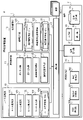
- FIG. 4 is a block diagram showing an example of the configuration of the information processing device 1 and the terminal 2. As shown in FIG. Here, the information processing device 1 will be described first, and then the terminal 2 will be described.
- the information processing apparatus 1 includes a rule management unit 10 that manages rules for device operation, a notification management unit 11 that notifies the terminal 2, a device management unit 12 that acquires device operation information and operates the device, and information
- the processing device 1 includes a communication unit 13 for communicating with external devices including the terminal 2 .
- FIG. 4 shows an example in which one communication unit 13 communicates with the terminal 2 and the device ND.
- the information processing apparatus 1 may perform communication via a different communication unit (that is, communication interface) according to the device of the communication partner.
- the rule management unit 10 manages rules. Specifically, the rule management unit 10 registers, determines, estimates, and discards rules. Rule management unit 10 includes rule registration unit 100 , rule determination unit 101 , rule estimation unit 102 , rule discard unit 103 , and rule management information storage unit 104 .
- the rule registration unit 100 registers rules from the rule information acquired from the notification management unit 11. Specifically, the rule information based on the device operation information is acquired from the notification management unit 11 and stored in the rule management information storage unit 104 .
- the rule determination unit 101 determines whether or not the device operation information satisfies the trigger conditions stored in the rule management information storage unit 104. If the conditions are met, the device management unit 12 is instructed to execute the remaining device operating procedures of the rule. Also, after the rule determination unit 101 starts executing the remaining device operation procedure of the rule, every time the device management unit 12 acquires the device operation information from the device ND, the user cancels the remaining device operation. It is determined whether or not it is information, and if it is device operation information to be canceled, an instruction is sent to the notification management unit 11 to inquire whether or not to cancel the registration of the rule.
- the device operation information for canceling the device operation is, for example, an operation by the user to turn off the power of the device ND after the device operation unit 120 has turned on the power of the device ND according to the device operation procedure of a predetermined rule. be.
- the user sets the mode of the device ND to "mode X”
- the user sets the mode of the device ND to "mode Y”.
- the rule estimation unit 102 estimates a rule (including trigger conditions) indicating a series of operation procedures for operating a user's device from one or more pieces of device operation information stored in the device management unit 12 .
- the rule estimating unit 102 describes a case where, for example, the user turns on the bathroom light and then turns on the bathroom heater. Based on this series of actions, if there is device operation information to turn on the power of the light in the bathroom, the device operation to turn on the heating in the bathroom is predicted as the next device operation.
- the rule estimating unit 102 determines that the series of equipment operation procedures is a rule if the series of equipment operation procedures appears a predetermined number of times (that is, a threshold value) or more. can be estimated.
- the rule estimating unit 102 uses an LSTM (Long Short Term Memory) network, which is a type of recursive neural network, to calculate the device operation procedure based on the time-series data of the normalized device operation information. may
- the rule estimating unit 102 applies the above pattern not only to the machine operation learning model by the LSTM network, but also to machine learning other than deep learning, such as the K nearest neighbor method, decision tree, random forest, SVM (Support Vector Machine), etc.
- Data used for estimation may also include date and time information.
- information such as the same time every day and a specific day of the week contributes to the estimation of the device operation procedure.
- the rule estimating unit 102 uses machine learning
- the rule estimating unit 102 operates as a machine learning device that receives device operation information generated by the user's operation of the device, generates a learned model, and stores it in the storage device. (for example, the rule management information storage unit 104).
- the device management unit 12 may execute the process of executing the linked device operation of the linked device based on the rule using the learned model. good.
- the rule discarding unit 103 discards the rule information stored in the rule management information storage unit 104 based on the rule discarding approval information acquired from the notification management unit 11 . For example, if the notification management unit 11 receives a notification result from the terminal 2 and the result of analysis is information indicating approval of discarding the rule, the rule discarding unit 103 identifies the rule from the obtained discard approval information. and discarded from the rule management information 104a.
- Rules are stored in the rule management information storage unit 104 as rule management information 104a.
- the notification management unit 11 manages notifications. Specifically, it generates and transmits notifications, obtains results, and analyzes results.
- Notification management unit 11 includes notification generation unit 110 , notification transmission unit 111 , notification result acquisition unit 112 , and notification result analysis unit 113 .
- the notification generation unit 110 generates a notification (that is, an inquiry) from the rule estimated by the rule management unit 10.
- the notification is, for example, an inquiry as to whether the user approves the registration of the inferred rule (including the trigger condition).
- the notification transmission unit 111 notifies the terminal 2 of the notification generated by the notification generation unit 110 .
- the notification result acquisition unit 112 acquires the notification result (that is, the reply to the inquiry). Specifically, the notification result acquisition unit 112 acquires the response as the notification result when the terminal 2 responds to the notification. For example, in response to the notification as to whether or not to register the estimated rule, the notification result acquisition unit 112 displays a question regarding the registration of the rule and "Yes" and "No” buttons on the terminal 2. The result of the selection is received as registration approval or registration disapproval in response to a "yes" or "no" operation.
- Notifications are not limited to notifications intended for screen display, and may be other types of notifications such as voice utterances.
- the notification result analysis unit 113 analyzes the notification received by the notification result acquisition unit 112, and transmits the rule to the rule management unit 10 as necessary. For example, the notification result analysis unit 113 analyzes the registration approval notification result, analyzes whether or not to register the rule, and transmits the information to the rule management unit 10 if the information indicates registration.
- the device management unit 12 manages devices. Specifically, the device management unit 12 acquires device operation information and performs device operation for the device ND.
- the device management section 12 includes a device operation section 120 , a device management information storage section 121 , a device operation information acquisition section 122 and a device operation information storage section 123 .
- the device operation information acquisition unit 122 acquires device operation information from the device ND.
- the device operation unit 120 operates the device ND.
- the device management information storage unit 121 stores device management information 121a.
- the device management information 121a is information about the device ND, and is generated for each device ND.
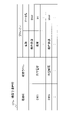
- FIG. 5 is a diagram showing the data structure and specific example of the device management information 121a stored in the device management information storage unit 121 of the device management unit 12 of the information processing apparatus 1 shown in FIG.
- the device management information storage unit 121 shown in FIG. 5 stores a device ID that is identification information of the device ND, device label information (“device label” in FIG. 5) that is the name of the device ND presented to the user on the terminal 2, and It stores property information (“property” in FIG. 5), which is the definition of variables that describe the state of the device.
- Property information is associated with property names and property data types. One or more pieces of property information exist for one device ID.
- the device ND with the device ID D001 has the device label information "bathroom light", and in the terminal 2, the device ND is presented to the user under the name "bathroom light”. Further, the device ND can have Bool type data as an operating state, and the operating state can be set and acquired. Note that in the Boolean type in the operating state, True is treated as power on, and False is treated as power off.
- the device operation information storage unit 123 stores the device operation information 123a acquired by the device operation information acquisition unit 122.
- the device operation information 123a may include date, time, and the like.
- the device operation unit 120 operates the device. For example, if the operation target is an air conditioner, which is a home appliance, the device operation unit 120 turns on/off the power of the device, switches modes such as heating/cooling, or changes temperature settings.
- the terminal 2 includes a terminal control unit 20 that controls all parts of the terminal 2, a terminal communication unit 21 that allows the terminal 2 to communicate with other devices, an input unit 22 that receives user input operations, and a terminal control unit 20. It includes a display unit 23 that displays a screen according to control, and a terminal storage unit 24 that stores various data used by the terminal 2 .
- the terminal control unit 20 includes an information notification unit 200, an inquiry response unit 201, and an information acquisition unit 202. These may be implemented by installing application software in the terminal 2, for example.
- the information notification unit 200 transmits various information acquired from the inquiry response unit 201 to the information processing device via the terminal communication unit 21 .
- the inquiry response unit 201 displays a predetermined user interface (UI) screen to notify about the rule. Specifically, the inquiry response unit 201 displays an inquiry screen regarding registration or cancellation of a rule as one of the UI screens, and allows various designations regarding the state of the rule estimated by the rule estimation unit 102 of the information processing apparatus 1. accept.
- UI user interface
- the information acquisition unit 202 acquires various types of information acquired from the notification transmission unit 111 of the notification management unit 11 of the information processing device 1 and outputs the information to the inquiry response unit 201 .
- FIGS. 6A and 6B are diagrams showing examples of display of inquiry information on the terminal 2.
- the inquiry screen is a screen for inquiring about registration or cancellation of a rule, and is shown in FIGS. 6A and 6B, for example.
- the inquiry screens of FIGS. 6A and 6B are screens for inquiring whether or not to approve the state of rule R001.
- a “Yes” button 233 and a registration date/time display portion 234 are included.
- the inquiry response unit 201 outputs inquiry information acquired by the information acquisition unit 202 .
- the inquiry response section 201 causes the trigger condition display section 230, the device operation display section 231, and the registration date and time display section 234 of the inquiry screen to display the rule information according to the inquiry screen data.
- FIG. 6A is an example of an inquiry about rule registration when a new rule is inferred.
- the trigger condition "bathroom light is on” and the device operation "bathroom heating is on” in rule R001 are displayed. It is Here, when the user selects the “No” button 232 , the inquiry response unit 201 outputs rule registration denial information to the information notification unit 200 . Then, the information notification unit 200 transmits the acquired rule registration denial information to the information processing apparatus 1 .
- inquiry response section 201 outputs rule registration approval information to information notification section 200 .
- the information notification unit 200 transmits the acquired rule registration approval information to the information processing device 1, and the information processing device 1 registers the rule.
- FIG. 6B is an example of an inquiry regarding rule cancellation when the rule is canceled. is displayed.
- the inquiry response unit 201 outputs rule discard denial information to the information notification unit 200 .
- the information notification unit 200 transmits the acquired rule discard denial information to the information processing apparatus 1 .
- the inquiry response section 201 outputs rule discard approval information to the information notification section 200 .
- the information notification unit 200 transmits the acquired rule discard approval information to the information processing device 1, and the information processing device 1 discards the rule.
- FIG. 7 is a block diagram showing an example of the hardware configuration of the information processing device 1 shown in FIGS. 1 and 4.
- the information processing device 1 has a processor 151 such as a CPU (Central Processing Unit), a memory 152 and a storage device 153 .
- the memory 152 is, for example, a volatile semiconductor memory such as RAM (Random Access Memory).
- the storage device 153 is, for example, a nonvolatile storage device such as a hard disk drive (HDD) or solid state drive (SSD).
- the information processing device 1 also has a communication unit 13 and an interface 154 .
- the processing circuitry may be dedicated hardware or processor 151 executing programs stored in memory 152 .
- the processor 151 may be any of a processing device, an arithmetic device, a microprocessor, a microcomputer, and a DSP (Digital Signal Processor).
- the processing circuit is the processor 151
- the information processing program is realized by software, firmware, or a combination of software and firmware.
- Software and firmware are written as programs and stored in memory 152 .
- the processor 151 reads out and executes the information processing program stored in the memory 152, thereby implementing the functions of the units shown in FIG.
- the information processing apparatus 1 may be partially realized by dedicated hardware and partially realized by software or firmware.
- the processing circuitry may implement each of the functions described above in hardware, software, firmware, or any combination thereof.
- FIG. 8 is a block diagram showing an example of the hardware configuration of the terminal 2 shown in FIGS. 1 and 4.
- the terminal 2 has a processor 251 such as a CPU, a memory 252 and a storage device 253 .
- Memory 252 is, for example, a RAM.
- the storage device 253 is, for example, an SSD.
- the terminal 2 also has a terminal communication unit 21 and a user interface 254 such as a touch panel.
- Each function of terminal 2 is realized by a processing circuit.
- the processing circuitry may be dedicated hardware or processor 251 executing programs stored in memory 252 .
- Processor 251 may be any of a processing unit, an arithmetic unit, a microprocessor, a microcomputer, and a DSP.
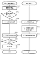
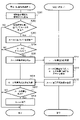
- FIG. 9 is a flowchart showing an example of processing for registering a rule executed by the information processing system 3 according to the first embodiment.
- the device operation information acquisition unit 122 of the device management unit 12 acquires device operation information from the device ND (step S101).
- the acquired device operation information is stored in the device operation information storage unit 123 of the device management unit 12 as the device operation information 123a.
- the rule estimation unit 102 of the rule management unit 10 estimates rules (including trigger conditions) based on the device operation information (step S102).
- the rule estimation unit 102 transmits the estimated rule information to the notification management unit 11.
- the rule estimation unit 102 ends the rule estimation process.
- the notification generation unit 110 of the notification management unit 11 acquires the estimated rule information, it generates a rule registration notification (that is, an inquiry as to whether or not to approve the registration). and transmits it to the terminal 2 (step S103).
- a rule registration notification that is, an inquiry as to whether or not to approve the registration.
- the information acquisition unit 202 of the terminal 2 receives the rule registration notification via the terminal communication unit 21 (step S111).
- the inquiry response unit 201 of the terminal 2 causes the display unit 23 to display an inquiry screen (for example, FIG. 6A) in accordance with the rule registration notification (step S112).
- the inquiry response unit 201 generates a rule registration approval result according to the user's operation, and outputs it to the information notification unit 200 .
- the information notification unit 200 notifies the information processing apparatus 1 of the acquired rule registration approval result via the terminal communication unit 21 (step S113).
- the notification management unit 11 of the information processing device 1 acquires the rule registration approval result via the communication unit 13 (step S104).
- the notification result acquisition unit 112 of the notification management unit 11 of the information processing device 1 outputs the rule registration approval result to the notification result analysis unit 113 .
- the notification result analysis unit 113 analyzes the rule registration approval result.
- Notification result analysis unit 113 analyzes the rule registration approval result, and outputs the rule information to rule registration unit 100 if the information indicates registration (YES in step S105). If the information does not indicate registration (NO in step S105), the processing for rule registration executed by the information processing device 1 and the terminal 2 ends.
- the rule registration unit 100 Upon acquiring the rule information, the rule registration unit 100 registers the rule in the rule management information storage unit 104 as the rule management information 104a (step S106). With this, the processing for registering the rule executed by the information processing device 1 and the terminal 2 ends.
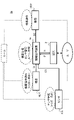
- FIG. 10 is a flow chart showing an example of processing for discarding a rule executed by the information processing system 3 .
- the device operation information acquisition unit 122 of the information processing device 1 acquires device operation information from the device ND (step S201).
- the acquired device operation information is stored in the device operation information storage unit 123 .
- the rule determination unit 101 determines whether or not the trigger condition is met based on the device operation information and the rule management information 104a registered in the rule management information storage unit 104 (step S202). . If the trigger condition is met (YES in step S202), the rule determination unit 101 issues an instruction to the device operation unit 120 of the device management unit 12 to execute the remaining device operation procedure of the rule, and executes the device operation. (Step S203). On the other hand, if the trigger condition is not met (NO in step S202), the information processing device 1 terminates the processing for discarding the rule.
- the rule determination unit 101 acquires device operation information for canceling the remaining device operation after starting execution of the remaining device operation procedure (YES in step S204)
- the rule determination unit 101 inquires whether or not to cancel the registration of the rule.
- the notification generation unit 110 of the notification management unit 11 is instructed to do so.
- the information processing apparatus 1 terminates the process.
- the notification generation unit 110 of the notification management unit 11 acquires the canceled rule information, it generates a rule discard notification and notifies it to the terminal 2 via the communication unit 13 by the notification transmission unit 111 (step S205).
- the information acquisition unit 202 of the terminal 2 receives the rule discard notification via the terminal communication unit 21 (step S211).
- the inquiry response unit 201 of the terminal 2 causes the display unit 23 to display an inquiry screen (for example, FIG. 6B) in accordance with the rule discard notification (step S212).
- the inquiry response unit 201 generates a rule abandonment approval result according to the user's operation, and outputs it to the information notification unit 200 .
- the information notification unit 200 notifies the information processing apparatus 1 of the acquired rule discard approval result via the terminal communication unit 21 (step S213).
- the notification management unit 11 of the information processing device 1 acquires the rule abandonment approval result via the communication unit 13 (step S206).
- the notification result acquisition unit 112 of the notification management unit 11 of the information processing device 1 outputs the rule discard approval result to the notification result analysis unit 113 .
- the notification result analysis unit 113 analyzes the rule abandonment approval result.
- Notification result analysis unit 113 analyzes the rule discard approval result, and outputs the rule information to rule discard unit 103 if the information indicates discard (YES in step S207). If the information does not indicate discarding (NO in step S207), the processing executed by the information processing device 1 and the terminal 2 ends.
- the rule discarding unit 103 Upon acquiring the rule information, the rule discarding unit 103 discards the rule information from the rule management information 104a (step S208). With this, the processing for discarding the rule executed by the information processing device 1 and the terminal 2 ends.
- the rule (including the trigger condition of the rule) is estimated from the device operation information that occurs in the user's daily life, and the rule ( (including trigger conditions for the rule), and by obtaining registration approval information from the user as to whether or not to register the rule, it is possible to register the rule according to the user's intention.
- the rule when the user acquires the device operation information for canceling the remaining device operation after the device operation of the rule is started, the rule is discarded by the user. If an inquiry is made as to whether the rule is valid and discard approval information is acquired from the user, the rule can be discarded, thereby facilitating the updating of the rule that changes daily.
- Embodiment 2 The information processing apparatus 1 according to Embodiment 1 estimates and registers a rule that defines a linked device operation, and discards the rule, based on device operation information generated by a user's device operation.
- the information processing apparatus 1a according to the second embodiment estimates a rule that defines the operation of a linked device based on device operation information generated by a user's device operation and sensor information acquired from a sensor. Register and discard rules.
- FIG. 11 is a diagram showing an overview of the information processing system 3a according to the second embodiment.
- components having the same functions as the components described in FIG. 1 are assigned the same reference numerals as those shown in FIG.
- the information processing device 1a operates according to rules.
- a rule consists of a series of operating procedures and trigger conditions for operating a user's device. That is, in the information processing system 3a, when predetermined sensor information that satisfies a predetermined trigger condition is acquired, the remaining device operations are executed based on the rule. This makes it possible to provide equipment operation services that combine various sensor information and equipment operation information.
- the information processing system 3a of FIG. 11 includes an information processing device 1 that provides device management, sensor management, and rule management, a device ND that transmits device operation information or executes device operation, a sensor NS that executes transmission of sensor information, and It includes a terminal 2 for inquiring about the rule status from the information processing device 1 .
- the sensor NS when the sensor NS detects a user, it transmits sensor information to the information processing device 1a. Then, the information processing device 1a executes the device operation of the device ND. Thereby, when the information of the sensor NS is acquired, the device operation of the device ND can be executed.
- the sensor NS may be one or more sensors.
- the device ND only needs to have the function of transmitting device operation information. Moreover, in Embodiment 2, an example in which the sensor NS is a human sensor will be described.
- FIG. 12 is a diagram showing an overview of rule estimation and rule registration executed by the information processing system 3a shown in FIG.
- the sensor information 142a accumulates the sensor information of the human sensor.
- the sensor information 142a of FIG. 12 includes time indicating time information, sensor information ID indicating identification information of sensor information, sensor ID indicating identification information of sensor, and property information.
- the human detection state of the human sensor in the bathroom where SE021 occurred at 19:00:03 is True (that is, human detection is present).
- the present embodiment is not limited to this example.
- the device operation information 123a in FIG. 12 device operation information in which the operation state of the bathroom heating that occurred at 19:00:06 by DE021 is True (that is, the power is on) will be described.
- the sensor information with the trigger condition of SE021 that is, the human detection reaction of the bathroom sensor
- the operation information, that is, the rule R002 for turning on the bathroom heater is estimated from the sensor information 142a and the device operation information 123a.
- the rule estimating unit 102 uses machine learning
- the rule estimating unit 102 operates as a machine learning device that receives device operation information generated by the user's operation of the device and sensor information, and generates a learned model.
- a storage device for example, the rule management information storage unit 104.
- the device management unit 12 may execute the process of executing the linked device operation of the linked device based on the rule using the learned model. good.
- the information processing apparatus 1a allows the user to estimate rules for device operation from sensor information and device operation information generated in daily life, and to register the rules based on the user's intention.
- FIG. 13 is a block diagram showing an example of the configuration of the information processing device 1a and the terminal 2 included in the information processing system 3a shown in FIG. 13, components having the same functions as the components described in FIG. 4 are given the same reference numerals as those shown in FIG.
- the information processing device 1a includes a sensor management section 14.
- the sensor management section 14 includes a sensor management section 14a.
- the communication unit 13 of the information processing device 1a can communicate with the sensor NS.
- FIG. 13 shows an example in which one communication unit 13 communicates with the terminal 2, the device ND, and the sensor NS.
- the sensor management unit 14 manages sensors. Specifically, the sensor information for the sensor NS is acquired.
- the sensor management section 14 includes a sensor management information storage section 140 , a sensor information acquisition section 141 and a sensor information storage section 142 .
- the sensor information acquisition unit 141 acquires sensor information from the sensor NS.
- FIG. 14 is a diagram showing the data structure and specific example of the sensor management information 140a stored in the sensor management information storage unit 140. As shown in FIG.
- the sensor management information 140a is information relating to the sensor NS, and is generated for each sensor NS.
- the sensor management information 141a of FIG. 14 includes a sensor ID that is identification information of the sensor NS, sensor label information (“sensor label” in FIG. 14) that is the name of the sensor NS presented to the user on the terminal 2, and sensor label information. It stores property information (“property” in FIG. 14), which is the definition of variables that describe the state.
- Property information is associated with property names and property data types. One or more pieces of property information exist for one sensor ID.
- the sensor NS with the sensor ID S001 has the sensor label information "bathroom human sensor", and in the terminal 2, the sensor NS is presented to the user under the name "bathroom human sensor”. be. Further, the sensor NS can have Boolean data as a human detection state, and the human detection state can be acquired. Note that the Boolean type in the human detection state is handled as human detection if True, and human non-detection if False.
- the sensor information storage unit 142 stores the sensor information acquired by the sensor information acquisition unit 141. This sensor information may include date, time, and the like.
- FIG. 15 is a flowchart showing an example of processing for registering a rule executed by the information processing system 3a according to the second embodiment. 15, components having the same functions as the components described in FIG. 9 are given the same reference numerals as those shown in FIG.
- step S121 rules are estimated based on sensor information and device operation information.
- the rule estimation unit 102 estimates rules (including trigger conditions) based on information stored in the sensor information storage unit 142 and the device operation information storage unit 123 . If it can be estimated (YES in step S121), the rule (including the trigger condition) is transmitted to the notification management unit 11, and the process proceeds to step S103. If the estimation could not be made (NO in step S121), the information processing device 1a terminates the process.
- the processing after step S103 is the same as that in FIG.
- rules are estimated from device operation information and sensor information that occur in the user's daily life, and the user's It is possible to register a rule according to the user's intention by notifying the user of the rule and obtaining registration approval information from the user as to whether or not to register the rule.
- the information processing apparatus 1a when the user acquires the device operation information for canceling the remaining device operation, the user is asked whether to discard the rule, and the user approves the discard. By discarding the rule when the information is acquired, it is possible to easily update the rule that changes on a daily basis.
- the device by inputting information of one or more of temperature/humidity sensor information and human sensor, a certain temperature, the device can also be operated using the season that matches the humidity conditions as one of the trigger conditions.
- the operation of the heating device during bathing and the operation of the heating device during drying of clothes can be made different.
Landscapes
- Engineering & Computer Science (AREA)
- Theoretical Computer Science (AREA)
- Software Systems (AREA)
- Evolutionary Computation (AREA)
- Artificial Intelligence (AREA)
- General Engineering & Computer Science (AREA)
- General Physics & Mathematics (AREA)
- Physics & Mathematics (AREA)
- Mathematical Physics (AREA)
- Computing Systems (AREA)
- Data Mining & Analysis (AREA)
- Computational Linguistics (AREA)
- Computer Networks & Wireless Communication (AREA)
- Medical Informatics (AREA)
- Signal Processing (AREA)
- Computer Vision & Pattern Recognition (AREA)
- Databases & Information Systems (AREA)
- Management, Administration, Business Operations System, And Electronic Commerce (AREA)
- Selective Calling Equipment (AREA)
Abstract
Description
〔情報処理システムの概要〕
図1は、実施の形態1に係る情報処理システム3の概要を示す図である。情報処理システム3は、機器操作を提供するシステムである。情報処理システム3は、複数の機器の連携に関するルールに基づいて機器操作を行う。ルールは、機器を操作する一連の操作手順とトリガー条件とを含む。すなわち、情報処理システム3において、情報処理装置1は、ユーザが機器(例えば、対象機器であるND1)に対するトリガー条件を満たす操作を行ったときに、ルールに基づいて残りの機器(例えば、対象機器と異なる連携機器であるND2)の機器操作を実行する。つまり、トリガー条件は、対象機器の操作に関する条件であり、対象機器の操作を示す機器操作情報D1がトリガー条件を満たす場合に、この対象機器と連携する連携機器が連携機器操作情報D2に基づいてルールに規定された動作を自動的に実行する。これにより、情報処理システム3は、多様な機器操作を組み合わせた機器操作のサービスを提供することができる。
情報処理装置1は、機器ND1から機器操作情報D1を取得すると、機器操作情報D1に基づいてルール(トリガー条件を含む)の推定を行う。ルール(トリガー条件を含む)の推定が行われると、情報処理装置1は、ユーザの端末2にルール(トリガー条件を含む)についての問合せI1を通知する。ルール(トリガー条件を含む)の問合せI1に対して、ユーザが端末2でルール(トリガー条件を含む)の登録の承認をする回答I2を送信した場合に、情報処理装置1は、当該ルール(トリガー条件を含む)の登録を行う。
以上の説明では、浴室電灯の電源がオンになった場合、浴室暖房の電源をオンにするというルールを例に説明した。しかしながら、例えば、季節が夏である場合に、ユーザは、浴室暖房の電源のオンが不要であると考えるかもしれない。
図4は、情報処理装置1と端末2との構成の例を示すブロック図である。ここでは、まず情報処理装置1について説明し、その後、端末2について説明する。
情報処理装置1は、機器操作のルールを管理するルール管理部10と、端末2に通知を行うための通知管理部11と、機器操作情報の取得及び機器操作を行う機器管理部12と、情報処理装置1が、端末2を含む外部機器と通信を行うための通信部13とを含む。図4には、1つの通信部13にて、端末2、及び機器NDと通信する例が示されている。ただし、情報処理装置1は、通信相手の機器に応じて、異なる通信部(すなわち、通信インターフェース)を介して通信を行ってもよい。
端末2は、端末2の各部を統括して制御する端末制御部20、端末2が他の機器と通信するための端末通信部21、ユーザの入力操作を受け付ける入力部22、端末制御部20の制御に従って画面を表示する表示部23、及び端末2が使用する各種データを記憶する端末記憶部24を含む。
図7は、図1及び図4に示される情報処理装置1のハードウェア構成の例を示すブロック図である。情報処理装置1は、CPU(Central Processing Unit)などのプロセッサ151と、メモリ152と、記憶装置153とを有している。メモリ152は、例えば、RAM(Random Access Memory)などの、揮発性の半導体メモリである。記憶装置153は、例えば、ハードディスクドライブ(HDD)又はソリッドステートドライブ(SSD)などの不揮発性の記憶装置である。また、情報処理装置1は、通信部13と、インタフェース154とを有している。
図9は、実施の形態1に係る情報処理システム3が実行するルールの登録のための処理の例を示すフローチャートである。ルールの登録に関する処理をするにあたり、まず、機器管理部12の機器操作情報取得部122は、機器NDから機器操作情報を取得する(ステップS101)。取得した機器操作情報は、機器管理部12の機器操作情報記憶部123に機器操作情報123aとして保存される。
図10は、情報処理システム3が実行するルールの破棄のための処理の例を示すフローチャートである。
実施の形態1に係る情報処理装置1は、ユーザが機器操作を行うことで生成される機器操作情報に基づいて、連携機器操作を規定するルールの推定及び登録、並びにルールの破棄を行う。これに対し、実施の形態2に係る情報処理装置1aは、ユーザが機器操作を行うことで発生する機器操作情報及びセンサから取得したセンサ情報に基づいて、連携機器操作を規定するルールの推定及び登録、並びにルールの破棄を行う。
図13は、図11に示される情報処理システム3aに含まれる情報処理装置1a及び端末2の構成の例を示すブロック図である。図13において、図4で説明した構成要素と同じ機能を有する構成要素には、図4に示される符号と同じ符号が付されている。図13に示されるように、情報処理装置1aは、センサ管理部14を含んでいる。情報処理装置1aの通信部13は、センサNSと通信可能である。
図15は、実施の形態2に係る情報処理システム3aが実行するルールの登録のための処理の例を示すフローチャートである。図15において、図9で説明した構成要素と同じ機能を有する構成要素には、図9に示される符号と同じ符号が付されている。
Claims (8)
- 端末を含む外部機器と通信を行う通信部と、
複数の機器の連携に関するルールを管理するルール管理部と、
通知管理部と、
機器管理部と、
を備え、
前記ルール管理部は、前記複数の機器のうちの第1の機器に対するユーザ操作を示す機器操作情報を取得し、前記機器操作情報に基づいて、前記複数の機器のうちの第2の機器の連携機器操作を開始させる条件であるトリガー条件を含む、前記ルールを推定し、
前記通知管理部は、前記通信部を介して、推定された前記ルールを含む問合せを前記端末に通知し、前記端末から前記ルールを登録するか否かの回答を取得し、
前記ルール管理部は、前記回答が前記ルールの登録の承認を示す場合、前記ルールを登録し、
前記機器管理部は、登録された前記ルールに含まれる前記トリガー条件を満たす前記機器操作情報が前記第1の機器に入力されたときに、前記ルールに基づいて前記連携機器操作を実行する
ことを特徴とする情報処理装置。 - センサによって検出された情報であるセンサ情報D3を取得するセンサ管理部をさらに備え、
前記ルール管理部は、前記機器操作情報と前記センサ情報とに基づいて、前記ルールを推定する
ことを特徴とする請求項1に記載の情報処理装置。 - 前記ルール管理部は、ユーザによる前記複数の機器の操作によって発生する前記機器操作情報を入力とする機械学習によって前記ルールを推定して学習済モデルを生成し、
前記機器管理部は、前記学習済モデルを用いて、前記ルールに基づく前記連携機器操作を実行する
ことを特徴とする請求項1に記載の情報処理装置。 - 前記ルール管理部は、ユーザによる前記複数の機器の操作によって発生する前記機器操作情報及び前記センサ情報を入力とする機械学習によって前記ルールを推定して学習済モデルを生成し、
前記機器管理部は、前記学習済モデルを用いて、前記ルールに基づく前記連携機器操作を実行する
ことを特徴とする請求項2に記載の情報処理装置。 - 前記機器管理部が前記連携機器操作のキャンセルを示す機器操作情報を取得したときに、前記通知管理部は、前記連携機器操作を規定する前記ルールの登録を破棄するか否かの問合せを前記端末に通知し、前記端末から前記ルールを破棄するか否かの回答情報を取得し、
前記ルール管理部は、前記回答情報が前記ルールの破棄の承認を示す場合、前記破棄の承認があった前記ルールを破棄する
ことを特徴とする請求項1から4のいずれか1項に記載の情報処理装置。 - 請求項1から5のいずれか1項に記載の情報処理装置と、
前記端末と、
を有することを特徴とする情報処理システム。 - 端末を含む外部機器と通信を行い、複数の機器の連携に関するルールを管理する情報処理装置によって実施される情報処理方法であって、
前記複数の機器のうちの第1の機器に対するユーザ操作を示す機器操作情報を取得し、前記機器操作情報に基づいて、前記複数の機器のうちの第2の機器の連携機器操作を開始させる条件であるトリガー条件を含む、前記ルールを推定するステップと、
推定された前記ルールを含む問合せを前記端末に通知し、前記端末から前記ルールを登録するか否かの回答を取得するステップと、
前記回答が前記ルールの登録の承認を示す場合、前記ルールを登録するステップと、
登録された前記ルールに含まれる前記トリガー条件を満たす前記機器操作情報が前記第1の機器に入力されたときに、前記ルールに基づいて前記連携機器操作を実行するステップと
を有することを特徴とする情報処理方法。 - 端末を含む外部機器と通信を行い、複数の機器の連携に関するルールを管理するコンピュータに、
前記複数の機器のうちの第1の機器に対するユーザ操作を示す機器操作情報を取得し、前記機器操作情報に基づいて、前記複数の機器のうちの第2の機器の連携機器操作を開始させる条件であるトリガー条件を含む、前記ルールを推定するステップと、
推定された前記ルールを含む問合せを前記端末に通知し、前記端末から前記ルールを登録するか否かの回答を取得するステップと、
前記回答が前記ルールの登録の承認を示す場合、前記ルールを登録するステップと、
登録された前記ルールに含まれる前記トリガー条件を満たす前記機器操作情報が前記第1の機器に入力されたときに、前記ルールに基づいて前記連携機器操作を実行するステップと
を実行させることを特徴とする情報処理プログラム。
Priority Applications (5)
| Application Number | Priority Date | Filing Date | Title |
|---|---|---|---|
| DE112021007876.3T DE112021007876T5 (de) | 2021-06-24 | 2021-06-24 | Informationsverarbeitungseinrichtung, informationsverarbeitungssystem, informationsverarbeitungsverfahren und informationsverarbeitungsprogramm |
| PCT/JP2021/023974 WO2022269869A1 (ja) | 2021-06-24 | 2021-06-24 | 情報処理装置、情報処理システム、情報処理方法、及び情報処理プログラム |
| US18/571,735 US20240121166A1 (en) | 2021-06-24 | 2021-06-24 | Information processing device, information processing system, information processing method, and storage medium storing information processing program |
| CN202180099556.9A CN117501251A (zh) | 2021-06-24 | 2021-06-24 | 信息处理装置、信息处理系统、信息处理方法和信息处理程序 |
| JP2022510185A JP7106032B1 (ja) | 2021-06-24 | 2021-06-24 | 情報処理装置、情報処理システム、情報処理方法、及び情報処理プログラム |
Applications Claiming Priority (1)
| Application Number | Priority Date | Filing Date | Title |
|---|---|---|---|
| PCT/JP2021/023974 WO2022269869A1 (ja) | 2021-06-24 | 2021-06-24 | 情報処理装置、情報処理システム、情報処理方法、及び情報処理プログラム |
Publications (1)
| Publication Number | Publication Date |
|---|---|
| WO2022269869A1 true WO2022269869A1 (ja) | 2022-12-29 |
Family
ID=82556745
Family Applications (1)
| Application Number | Title | Priority Date | Filing Date |
|---|---|---|---|
| PCT/JP2021/023974 Ceased WO2022269869A1 (ja) | 2021-06-24 | 2021-06-24 | 情報処理装置、情報処理システム、情報処理方法、及び情報処理プログラム |
Country Status (5)
| Country | Link |
|---|---|
| US (1) | US20240121166A1 (ja) |
| JP (1) | JP7106032B1 (ja) |
| CN (1) | CN117501251A (ja) |
| DE (1) | DE112021007876T5 (ja) |
| WO (1) | WO2022269869A1 (ja) |
Cited By (2)
| Publication number | Priority date | Publication date | Assignee | Title |
|---|---|---|---|---|
| JP7595817B1 (ja) * | 2023-11-09 | 2024-12-06 | 三菱電機株式会社 | 制御システム、制御方法、および制御プログラム |
| WO2025099957A1 (ja) * | 2023-11-09 | 2025-05-15 | 三菱電機株式会社 | 制御システム、制御方法、および制御プログラム |
Citations (4)
| Publication number | Priority date | Publication date | Assignee | Title |
|---|---|---|---|---|
| JPH087188A (ja) * | 1994-06-22 | 1996-01-12 | Tokyo Gas Co Ltd | 人間活動監視補助装置 |
| JP2009044247A (ja) * | 2007-08-06 | 2009-02-26 | Panasonic Electric Works Co Ltd | 機器制御システム |
| JP2017102643A (ja) * | 2015-12-01 | 2017-06-08 | シャープ株式会社 | 連携サーバ、連携システム、および連携サーバの制御方法 |
| WO2017212793A1 (ja) * | 2016-06-10 | 2017-12-14 | パナソニックIpマネジメント株式会社 | 制御システム、及び、制御方法 |
Family Cites Families (14)
| Publication number | Priority date | Publication date | Assignee | Title |
|---|---|---|---|---|
| US20060213000A1 (en) * | 2005-03-25 | 2006-09-28 | Kimble Christopher J | Automatic energy-efficient bathroom exhaust fan controller |
| US8171325B2 (en) * | 2008-12-03 | 2012-05-01 | International Business Machines Corporation | Computing component and environment mobility |
| US9208676B2 (en) * | 2013-03-14 | 2015-12-08 | Google Inc. | Devices, methods, and associated information processing for security in a smart-sensored home |
| US9558043B2 (en) * | 2013-01-25 | 2017-01-31 | Cisco Technology Inc. | System and method for abstracting and orchestrating mobile data networks in a network environment |
| US9520054B2 (en) * | 2013-10-07 | 2016-12-13 | Google Inc. | Mobile user interface for smart-home hazard detector configuration |
| WO2015127566A1 (en) * | 2014-02-28 | 2015-09-03 | Appareils Connectés Casa Ltée | Thermostat unit and associated system and method |
| US9841205B2 (en) * | 2015-05-20 | 2017-12-12 | Google Llc | Systems and methods of detection with active infrared sensors |
| JP6819614B2 (ja) * | 2016-01-18 | 2021-01-27 | 日本電気株式会社 | 情報処理システム、デバイス登録方法、情報処理装置、通信端末およびそれらの制御方法と制御プログラム |
| US10754673B2 (en) * | 2017-05-08 | 2020-08-25 | Google Llc | Smart device configuration guidance via automated assistant interface of separate client device |
| PL3416337T3 (pl) * | 2017-06-12 | 2020-04-30 | Smart Place Ag | Urządzenie do automatyzacji domu lub budynku |
| US10977579B2 (en) * | 2018-08-27 | 2021-04-13 | Vmware, Inc. | Adversarial automated reinforcement-learning-based application-manager training |
| US20200120163A1 (en) * | 2018-10-12 | 2020-04-16 | Thingify Private Limited | Managing data and personification of iot devices in multiple networks |
| US11032312B2 (en) * | 2018-12-19 | 2021-06-08 | Abnormal Security Corporation | Programmatic discovery, retrieval, and analysis of communications to identify abnormal communication activity |
| JP7012764B2 (ja) * | 2020-03-02 | 2022-01-28 | キヤノン株式会社 | 情報処理装置、情報処理方法及びプログラム |
-
2021
- 2021-06-24 JP JP2022510185A patent/JP7106032B1/ja active Active
- 2021-06-24 DE DE112021007876.3T patent/DE112021007876T5/de active Pending
- 2021-06-24 US US18/571,735 patent/US20240121166A1/en active Pending
- 2021-06-24 WO PCT/JP2021/023974 patent/WO2022269869A1/ja not_active Ceased
- 2021-06-24 CN CN202180099556.9A patent/CN117501251A/zh not_active Withdrawn
Patent Citations (4)
| Publication number | Priority date | Publication date | Assignee | Title |
|---|---|---|---|---|
| JPH087188A (ja) * | 1994-06-22 | 1996-01-12 | Tokyo Gas Co Ltd | 人間活動監視補助装置 |
| JP2009044247A (ja) * | 2007-08-06 | 2009-02-26 | Panasonic Electric Works Co Ltd | 機器制御システム |
| JP2017102643A (ja) * | 2015-12-01 | 2017-06-08 | シャープ株式会社 | 連携サーバ、連携システム、および連携サーバの制御方法 |
| WO2017212793A1 (ja) * | 2016-06-10 | 2017-12-14 | パナソニックIpマネジメント株式会社 | 制御システム、及び、制御方法 |
Cited By (2)
| Publication number | Priority date | Publication date | Assignee | Title |
|---|---|---|---|---|
| JP7595817B1 (ja) * | 2023-11-09 | 2024-12-06 | 三菱電機株式会社 | 制御システム、制御方法、および制御プログラム |
| WO2025099957A1 (ja) * | 2023-11-09 | 2025-05-15 | 三菱電機株式会社 | 制御システム、制御方法、および制御プログラム |
Also Published As
| Publication number | Publication date |
|---|---|
| DE112021007876T5 (de) | 2024-04-11 |
| CN117501251A (zh) | 2024-02-02 |
| JP7106032B1 (ja) | 2022-07-25 |
| JPWO2022269869A1 (ja) | 2022-12-29 |
| US20240121166A1 (en) | 2024-04-11 |
Similar Documents
| Publication | Publication Date | Title |
|---|---|---|
| JP5803249B2 (ja) | 情報処理装置、情報処理方法、及びプログラム | |
| EP3055844B1 (en) | Smart-home hazard detector providing useful follow up communications to detection events | |
| KR102740291B1 (ko) | 전자 장치에서 스케줄 관리 방법 및 장치 | |
| JP4741500B2 (ja) | 機器制御装置、機器、機器制御装置の制御方法、プログラムおよび機器制御システム | |
| JP7106032B1 (ja) | 情報処理装置、情報処理システム、情報処理方法、及び情報処理プログラム | |
| JP2012234421A (ja) | 情報処理装置、情報処理方法、及びプログラム | |
| JP5850240B2 (ja) | 電力管理装置 | |
| CN111023475B (zh) | 网络系统、服务器及信息处理方法 | |
| JP7747461B2 (ja) | 情報出力方法、情報出力装置及びプログラム | |
| WO2014103307A1 (ja) | 制御方法 | |
| Vastardis et al. | A user behaviour-driven smart-home gateway for energy management | |
| JP2025164908A (ja) | 機器制御方法及び機器制御装置 | |
| CN109196352B (zh) | 用于通过使用声学信号来监视对象及其状态的系统和方法 | |
| CN104777754B (zh) | 一种虚拟设备创建方法及装置 | |
| RU2622859C2 (ru) | Способ для реализации инсталляции прибора с интеллектуальным аппаратным обеспечением и устройство для того же | |
| CN110093739B (zh) | 运行控制方法、装置、洗涤设备和计算机可读存储介质 | |
| JP2005260919A (ja) | コントローラ、プログラムおよび記憶媒体 | |
| JP6103006B2 (ja) | 情報処理装置、情報処理方法、及びプログラム | |
| CN112789635A (zh) | 信息提供方法 | |
| JP2003196412A (ja) | 保守管理サーバおよび機器 | |
| KR101801952B1 (ko) | 콘텍스트-기초 대기 전력 절감 방법 및 장치 | |
| Lim et al. | CASPRE: A context-aware standby power reduction scheme for household appliances | |
| CN114265647B (zh) | 交互界面的显示方法、控制终端、空调器及介质 | |
| US20210319791A1 (en) | Electronic apparatus and controlling method thereof | |
| JP7764587B2 (ja) | 機器制御装置、機器制御方法、プログラム及び機器制御システム |
Legal Events
| Date | Code | Title | Description |
|---|---|---|---|
| ENP | Entry into the national phase |
Ref document number: 2022510185 Country of ref document: JP Kind code of ref document: A |
|
| 121 | Ep: the epo has been informed by wipo that ep was designated in this application |
Ref document number: 21947154 Country of ref document: EP Kind code of ref document: A1 |
|
| WWE | Wipo information: entry into national phase |
Ref document number: 202180099556.9 Country of ref document: CN |
|
| WWE | Wipo information: entry into national phase |
Ref document number: 18571735 Country of ref document: US |
|
| WWE | Wipo information: entry into national phase |
Ref document number: 112021007876 Country of ref document: DE |
|
| 122 | Ep: pct application non-entry in european phase |
Ref document number: 21947154 Country of ref document: EP Kind code of ref document: A1 |