WO2022269751A1 - 工作機械の制御装置 - Google Patents
工作機械の制御装置 Download PDFInfo
- Publication number
- WO2022269751A1 WO2022269751A1 PCT/JP2021/023589 JP2021023589W WO2022269751A1 WO 2022269751 A1 WO2022269751 A1 WO 2022269751A1 JP 2021023589 W JP2021023589 W JP 2021023589W WO 2022269751 A1 WO2022269751 A1 WO 2022269751A1
- Authority
- WO
- WIPO (PCT)
- Prior art keywords
- swing
- tool
- rocking
- machine tool
- control device
- Prior art date
- Legal status (The legal status is an assumption and is not a legal conclusion. Google has not performed a legal analysis and makes no representation as to the accuracy of the status listed.)
- Ceased
Links
Images




Classifications
-
- B—PERFORMING OPERATIONS; TRANSPORTING
- B23—MACHINE TOOLS; METAL-WORKING NOT OTHERWISE PROVIDED FOR
- B23Q—DETAILS, COMPONENTS, OR ACCESSORIES FOR MACHINE TOOLS, e.g. ARRANGEMENTS FOR COPYING OR CONTROLLING; MACHINE TOOLS IN GENERAL CHARACTERISED BY THE CONSTRUCTION OF PARTICULAR DETAILS OR COMPONENTS; COMBINATIONS OR ASSOCIATIONS OF METAL-WORKING MACHINES, NOT DIRECTED TO A PARTICULAR RESULT
- B23Q15/00—Automatic control or regulation of feed movement, cutting velocity or position of tool or work
- B23Q15/007—Automatic control or regulation of feed movement, cutting velocity or position of tool or work while the tool acts upon the workpiece
- B23Q15/12—Adaptive control, i.e. adjusting itself to have a performance which is optimum according to a preassigned criterion
-
- G—PHYSICS
- G05—CONTROLLING; REGULATING
- G05B—CONTROL OR REGULATING SYSTEMS IN GENERAL; FUNCTIONAL ELEMENTS OF SUCH SYSTEMS; MONITORING OR TESTING ARRANGEMENTS FOR SUCH SYSTEMS OR ELEMENTS
- G05B19/00—Program-control systems
- G05B19/02—Program-control systems electric
- G05B19/18—Numerical control [NC], i.e. automatically operating machines, in particular machine tools, e.g. in a manufacturing environment, so as to execute positioning, movement or co-ordinated operations by means of program data in numerical form
- G05B19/4093—Numerical control [NC], i.e. automatically operating machines, in particular machine tools, e.g. in a manufacturing environment, so as to execute positioning, movement or co-ordinated operations by means of program data in numerical form characterised by part programming, e.g. entry of geometrical information as taken from a technical drawing, combining this with machining and material information to obtain control information, named part program, for the NC machine
-
- B—PERFORMING OPERATIONS; TRANSPORTING
- B23—MACHINE TOOLS; METAL-WORKING NOT OTHERWISE PROVIDED FOR
- B23B—TURNING; BORING
- B23B29/00—Holders for non-rotary cutting tools; Boring bars or boring heads; Accessories for tool holders
- B23B29/04—Tool holders for a single cutting tool
- B23B29/12—Special arrangements on tool holders
- B23B29/125—Vibratory toolholders
-
- G—PHYSICS
- G05—CONTROLLING; REGULATING
- G05B—CONTROL OR REGULATING SYSTEMS IN GENERAL; FUNCTIONAL ELEMENTS OF SUCH SYSTEMS; MONITORING OR TESTING ARRANGEMENTS FOR SUCH SYSTEMS OR ELEMENTS
- G05B2219/00—Program-control systems
- G05B2219/30—Nc systems
- G05B2219/49—Nc machine tool, till multiple
- G05B2219/49055—Remove chips from probe, tool by vibration
Definitions
- the present disclosure relates to a control device for machine tools.
- the workpiece has a tapered shape or arc shape
- there are multiple feed axes for example, the Z axis and the X axis
- the load on the machine tool is increased because the multiple axes are oscillated at the same time. Therefore, a technology has been proposed that can reduce the load on the machine tool while achieving chip shredding by changing the swing direction from the direction along the machining path to a direction different from the direction along the machining path at the tapered portion of the workpiece. (See, for example, Patent Document 1).
- FIG. 7 is a diagram showing an example of conventional oscillating cutting.
- cutting is performed by moving the tool T by the feed shaft in the feed direction along the generatrix of the outer peripheral surface of the work W rotated by the main shaft S.
- the tapered portion W1 of the workpiece W is cut by the tool T as shown in FIG. be done.
- from the rocking direction along the machining path indicated by the black arrow in FIG. is changed to the swing direction in which the vibration component of is reduced.
- the swing component in the Z-axis direction is increased by changing the swing direction, while the swing component in the X-axis direction is decreased, so that the load on the machine tool can be sufficiently reduced.
- the X-axis inertia of the machine tool is much greater than the Z-axis inertia. That is, in the above-described conventional oscillating cutting, the effect of reducing the load on the machine tool depends on the configuration of the machine tool.
- One aspect of the present disclosure is a control device for a machine tool that relatively oscillates a tool and a workpiece to perform oscillating cutting, comprising: a cutting angle acquisition unit that acquires a cutting angle of the tool; and a cutting depth of the tool.
- a swing amplitude calculator for calculating a swing amplitude necessary for shredding chips in an arbitrary swing direction based on the angle, and a swing direction is determined based on the calculation result of the swing amplitude calculator.
- a control device for a machine tool comprising: a swing direction determination unit; and a swing motion control unit that controls the swing motion in the swing direction determined by the swing direction determination unit based on machining conditions. be.
- the load on the machine tool can be reduced in general without depending on the configuration of the machine tool.
- FIG. 1 is a diagram showing a machine tool control device according to an embodiment of the present disclosure
- FIG. FIG. 4 is a diagram showing the cutting angle of the tool
- It is a figure which shows the calculation method of swing amplitude.
- It is a figure showing the 1st example of rocking cutting concerning this embodiment.
- It is a figure which shows the 2nd example of the oscillation cutting which concerns on this embodiment.
- It is a figure which shows the 3rd example of the oscillation cutting which concerns on this embodiment.
- FIG. 1 is a diagram showing a control device 1 for a machine tool according to this embodiment.
- a control device 1 for a machine tool according to this embodiment includes at least one main shaft for relatively rotating a cutting tool (hereinafter referred to as a tool) and a work, and at least one feed shaft for relatively moving the tool with respect to the work. , the workpiece is cut by the tool.
- FIG. 1 shows only the motor 3 for driving one feed shaft.
- the machine tool control device 1 performs oscillating cutting by operating the main shaft and the feed shaft. That is, the control device 1 of the machine tool performs cutting while rotating the tool and the work relatively and swinging the tool and the work relatively.
- the tool path which is the trajectory of the tool, is set such that the current path partially overlaps the previous path, and the portion machined by the previous path is included in the current path.
- air cutting occurs in which the cutting edge of the tool separates from the surface of the workpiece, and chips that are continuously generated by the cutting process are reliably shredded.
- the machine tool control device 1 includes, for example, memories such as ROM (read only memory) and RAM (random access memory), a CPU (control processing unit), and a communication control unit, which are connected to each other via a bus. It is configured using a computer. As shown in FIG. 1, a machine tool control device 1 includes a first storage unit 11, a cutting angle acquisition unit 12, an oscillation amplitude calculation unit 13, an oscillation direction determination unit 14, and an oscillation operation control unit. A unit 15 and a second storage unit 16 are provided, and the functions and operations of these units can be achieved by the cooperation of the CPU mounted on the computer, the memory, and the control program stored in the memory. .
- memories such as ROM (read only memory) and RAM (random access memory)
- CPU control processing unit
- a communication control unit which are connected to each other via a bus. It is configured using a computer.
- a machine tool control device 1 includes a first storage unit 11, a cutting angle acquisition unit 12, an oscillation amplitude calculation unit 13, an oscillation direction determination unit 14,
- a host computer such as a CNC (Computer Numerical Controller), a PLC (Programmable Logic Controller), or the like is connected to the control device 1 of the machine tool.
- machining conditions such as rotation speed and feed rate, and oscillation conditions such as oscillation frequency are input to the control device 1 of the machine tool from these host computers.
- the first storage unit 11 stores the cutting angle of the tool.
- FIG. 2 is a diagram showing the cutting angle ⁇ 1 of the tool T.
- FIG. 2 to FIG. 6, which will be described later each shows an example of cutting by moving the tool T by the feed shaft in the feed direction along the generatrix of the outer peripheral surface of the work W rotated by the main shaft S.
- the present embodiment is not limited to such outer diameter machining, and can also be applied to inner diameter machining. Further, this embodiment can also be applied to a configuration in which the tool T rotates around the central axis of the work W and the work W moves relative to the tool T in the feed direction. 2 to 7, the center axis of the workpiece W is the Z axis, and the direction orthogonal to the Z axis is the X axis.
- the cutting angle ⁇ 1 of the tool T means the angle from the Z-axis direction, which is the central axis direction of the work W, to the flank T1 of the tool T.
- the flank T1 of the tool T means the surface of the cutting edge of the tool T on the workpiece W side and in the machining direction (see the black arrow in FIG. 2).
- This cutting angle ⁇ 1 is set to a desired angle in advance for each of a plurality of tools T, and does not depend on the taper angle of the machined surface. More specifically, the cutting angle ⁇ 1 preset for each tool T is associated with each tool T and stored in the first storage unit.
- the cutting angle acquisition unit 12 acquires the cutting angle ⁇ 1 of the tool T. Specifically, the cutting angle acquisition unit 12 reads the cutting angle ⁇ 1 corresponding to the tool from the first storage unit 11 based on the tool data acquired from the machining program input to the control device 1 of the machine tool. to get. The obtained cutting angle ⁇ 1 of the tool T is output to the oscillation amplitude calculator 13, which will be described later.
- the oscillation amplitude calculation section 13 calculates the oscillation amplitude necessary for shredding chips in an arbitrary oscillation direction.
- the calculated rocking amplitude in each rocking direction is output to the rocking direction determination unit 14 and rocking motion control unit 15, which will be described later.
- the swing amplitude in this embodiment includes not only the swing amplitude itself but also the swing amplitude magnification.
- FIG. 3 is a diagram showing a method of calculating the swing amplitude in the swing amplitude calculator 13.
- the mode of swinging along the conventional machining path is referred to as "before change”
- the mode of swinging in an arbitrary swing direction different from the direction along the machining path is referred to as "after change”.
- the oscillation amplitude A' required for shredding chips in the oscillation direction after the oscillation direction is changed is the same as that of the chips in the oscillation direction along the conventional machining path before the change.
- the rocking direction determination unit 14 determines the rocking direction based on the rocking amplitude calculated by the rocking amplitude calculation unit 13 .
- the swing direction determination unit 14 has a swing amplitude A′ smaller than the swing amplitude A of the swing motion in the direction along the machining path within the range of swing directions in which chips can be shredded. determine the swing direction. This generally reduces the load on the machine tool due to the swing motion.
- the swinging direction determining unit 14 selects a direction in which the combined swinging amplitude of the swinging amplitude component in the Z-axis direction and the swinging amplitude component in the X-axis direction becomes smaller. is determined as the oscillation direction.
- the swinging direction determination unit 14 determines the direction perpendicular to the flank T1 of the tool T as the swinging direction. In this case, the minimum oscillation amplitude that can shred chips can be obtained, and the load on the machine tool is minimized while shredding chips.
- the second storage unit 16 stores processing conditions for the workpiece W and the like.
- the machining conditions for the workpiece W include the relative rotation speed of the workpiece W and the tool T around the central axis of the workpiece W, the relative feed speed of the tool T and the workpiece W, the position command of the feed axis, and the like.
- the second storage unit 16 stores a machining program to be executed by the machine tool, and the CPU in the control device 1 of the machine tool reads out the rotation speed and the feed speed as machining conditions from the machining program and sends them to the swing operation control unit 15. It may be configured to output Further, the second storage unit 16, a position command generating unit in the rocking motion control unit 15, which will be described later, and the like may be provided in the host computer.
- the swing motion control unit 15 controls the swing motion in the swing direction determined by the swing direction determination unit 14 based on the machining conditions.
- the swing motion control unit 15 includes various functional units (any (also not shown).
- the position command generation unit reads the machining conditions stored in the second storage unit 16 and generates a position command as a movement command for the motor 3 based on the machining conditions. Specifically, the position command generator generates a position command for each feed axis based on the relative rotational speed of the work W and the tool T about the central axis of the work W and the relative feed speed of the tool T and the work W. (movement command) is generated.
- the swing command generator generates a swing command.
- the swing command generator may generate the swing command from the swing conditions such as the swing amplitude magnification and the swing frequency multiplier and the machining conditions, and generate the swing command from the swing conditions such as the swing amplitude and the swing frequency. may be generated.
- the swing command generation unit is adapted to the swing conditions such as the swing amplitude calculated by the swing amplitude calculator 13 and the swing frequency input from the host computer and stored in the second storage unit. Based on this, a swing command is generated.
- the superimposed command generator calculates a position deviation, which is the difference between the position feedback based on the position detection by the encoder of the motor 3 of the feed shaft, and the position command.
- a superimposed command is generated by superimposing the generated swing command.
- the swing command may be superimposed on the position command instead of the position deviation.
- the learning control unit calculates the correction amount of the superimposed command based on the superimposed command, and adds the calculated correction amount to the superimposed command to correct the superimposed command.
- the learning control unit has a memory, stores the oscillation phase and the correction amount in the memory in association with each other in one period or a plurality of periods of the oscillation, and determines the phase delay of the oscillation operation according to the responsiveness of the motor 3.
- the superposition command stored in the memory is read out at the timing when compensation is possible and is output as a correction amount. If the oscillation phase for which the correction amount is to be output does not exist in the oscillation phases stored in the memory, the correction amount to be output may be calculated from the correction amounts having the oscillation phases close to each other. In general, the higher the oscillation frequency, the greater the positional deviation relative to the oscillation command. Therefore, by performing the correction by this learning control unit, it is possible to improve the ability to follow the periodic oscillation command.
- the position/speed control unit generates a torque command for the motor 3 that drives the feed shaft based on the superimposed command after addition of the correction amount, and controls the motor 3 with the generated torque command. Thereby, machining is performed while the tool T and the work W are relatively swung.
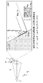
- FIG. 4 is a diagram showing a first example of oscillating cutting according to this embodiment.
- the swing direction is such that the swing amplitude A' is smaller than the swing amplitude A of the swing motion in the direction along the machining path.
- the swing amplitude A′ in the swing direction after the change, which enables chip shredding is smaller than the swing amplitude A of the swing motion in the direction along the machining path. It is possible to reduce the load.
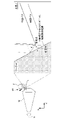
- FIG. 5 is a diagram showing a second example of oscillating cutting according to this embodiment.
- This second example is an example when the direction perpendicular to the flank T1 of the tool T is determined as the swinging direction within the range of swinging directions in which chips can be shredded.
- the swing amplitude A' that enables chip shredding when the swing direction is the direction perpendicular to the flank T1 of the tool T is the swing of the swing motion in the direction along the machining path. It is considerably smaller than the dynamic amplitude A, allowing minimization of the load on the machine tool.
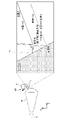
- FIG. 6 is a diagram showing a third example of oscillating cutting according to this embodiment.
- a columnar or cylindrical workpiece W is used, and the tool T is oscillated in a direction perpendicular to the flank T1 within a range of oscillating directions in which chips can be shredded. This is an example when the direction is determined.
- the shape of the workpiece W does not have a tapered portion or an arcuate portion and the feed axis is a specific one (the Z axis in FIG.
- the The swing amplitude A' that enables chip shredding when the direction perpendicular to the flank T1 is the swing direction is considerably smaller than the swing amplitude A of the swing motion in the direction along the machining path, and the load on the machine tool is reduced. can be minimized.
- the shape of the workpiece W is not limited in the swing cutting according to this embodiment. That is, even if a plurality of feed axes (Z-axis and X-axis) are required because the workpiece W has a tapered portion or an arc-shaped portion on the machining surface, the workpiece W may be columnar or cylindrical and the feed axis may be specified. Even if one axis (Z-axis) is enough, it is applicable. Therefore, the rocking motion control unit 15 according to the present embodiment can control the rocking motion from the rocking motion of rocking the plurality of feed shafts or from the rocking motion of rocking only a specific one of the plurality of feed shafts. It is configured to change to the rocking motion in the rocking direction determined by the moving direction determination unit 14 .
- a cutting angle acquisition unit 12 that acquires the cutting angle of the tool T, and a swing amplitude that calculates the swing amplitude necessary for shredding chips in an arbitrary swing direction based on the cutting angle of the tool T.
- a calculation unit 13 a swing direction determination unit 14 that determines the swing direction based on the calculation result of the swing amplitude calculation unit 13;
- a control device 1 for a machine tool is configured by including a swing motion control section 15 for controlling the swing motion.
- the oscillating amplitude at which chips can be shredded is calculated. Both are greatly different in that after calculating the possible swing amplitude, the swing direction is determined based on the calculated swing amplitude. Therefore, according to the present embodiment, it is possible to select and determine the swinging direction in which the swinging amplitude is smaller than the swinging amplitude of the swinging motion in the direction along the machining path, thereby reducing the load on the machine tool. It is possible. As a result, according to this embodiment, the load on the machine tool can be reduced in general without depending on the configuration of the machine tool.
- the oscillating direction is oscillated with an oscillating amplitude smaller than the oscillating amplitude of the oscillating motion in the direction along the machining path within the range of the oscillating direction in which chips can be shredded. It was configured. As a result, the load on the machine tool can be reduced more reliably while shredding the chips, compared to the conventional swing motion in the direction along the machining path.
- the tool T is configured to swing in a direction perpendicular to the flank T1.
- the load on the machine tool can be reduced and the load on the machine tool can be minimized while shredding the chips. can.
- the swing motion control unit 15 controls the swing motion in the swing direction determined by the swing direction determination unit 14 from the swing motion for swinging only a specific one of the plurality of feed shafts. It was configured to change to operation.
- the swing motion control unit 15 not only when the workpiece W has a tapered portion or an arcuate portion on the machining surface and a plurality of feed axes (Z-axis and X-axis) are required, but also when the workpiece W It can be applied even in a case where one specific feed axis (Z-axis) is sufficient for a columnar or cylindrical shape, and the above effects can be obtained.
Landscapes
- Engineering & Computer Science (AREA)
- Mechanical Engineering (AREA)
- Physics & Mathematics (AREA)
- Geometry (AREA)
- Human Computer Interaction (AREA)
- Manufacturing & Machinery (AREA)
- General Physics & Mathematics (AREA)
- Automation & Control Theory (AREA)
- Turning (AREA)
- Numerical Control (AREA)
Abstract
Description
[数1]
A’=A×(cosθ-sinθ/tan(θ+θ1-θ2)) ・・・数式(1)
[数2]
合成揺動振幅=((Z軸振幅)2+(X軸振幅)2)1/2 ・・・数式(2)
11 第1記憶部
12 切込み角取得部
13 揺動振幅算出部
14 揺動方向決定部
15 揺動動作制御部
16 第2記憶部
3 モータ
S 主軸
T 工具
W ワーク
W1 テーパ部
θ1 切込み角
Claims (4)
- 工具とワークを相対的に揺動させて揺動切削を行う工作機械の制御装置であって、
前記工具の切込み角を取得する切込み角取得部と、
前記工具の切込み角に基づいて、任意の揺動方向における切屑の細断に必要な揺動振幅を算出する揺動振幅算出部と、
前記揺動振幅算出部の算出結果に基づいて、揺動方向を決定する揺動方向決定部と、
加工条件に基づいて、前記揺動方向決定部で決定された前記揺動方向の揺動動作を制御する揺動動作制御部と、を備える、工作機械の制御装置。 - 前記揺動方向決定部は、切屑の細断が可能な揺動方向の範囲の中で、加工経路に沿う方向の揺動動作の揺動振幅よりも小さい揺動振幅となる揺動方向を決定する、請求項1に記載の工作機械の制御装置。
- 前記揺動方向決定部は、前記工具の刃先における前記ワーク側の面で且つ加工方向側の面である前記工具の逃げ面に対して垂直な方向を前記揺動方向として決定する、請求項1に記載の工作機械の制御装置。
- 前記揺動動作制御部は、複数の送り軸のうち特定の1軸のみを揺動させる揺動動作から、前記揺動方向決定部で決定された前記揺動方向の揺動動作へと変更する、請求項1から3いずれかに記載の工作機械の制御装置。
Priority Applications (5)
| Application Number | Priority Date | Filing Date | Title |
|---|---|---|---|
| US18/567,178 US20240131648A1 (en) | 2021-06-22 | 2021-06-21 | Machine tool control device |
| PCT/JP2021/023589 WO2022269751A1 (ja) | 2021-06-22 | 2021-06-22 | 工作機械の制御装置 |
| DE112021007567.5T DE112021007567T5 (de) | 2021-06-22 | 2021-06-22 | Werkzeugmaschinen-Steuervorrichtung |
| JP2023529271A JP7652899B2 (ja) | 2021-06-22 | 2021-06-22 | 工作機械の制御装置 |
| CN202180099221.7A CN117529379A (zh) | 2021-06-22 | 2021-06-22 | 机床的控制装置 |
Applications Claiming Priority (1)
| Application Number | Priority Date | Filing Date | Title |
|---|---|---|---|
| PCT/JP2021/023589 WO2022269751A1 (ja) | 2021-06-22 | 2021-06-22 | 工作機械の制御装置 |
Publications (1)
| Publication Number | Publication Date |
|---|---|
| WO2022269751A1 true WO2022269751A1 (ja) | 2022-12-29 |
Family
ID=84545310
Family Applications (1)
| Application Number | Title | Priority Date | Filing Date |
|---|---|---|---|
| PCT/JP2021/023589 Ceased WO2022269751A1 (ja) | 2021-06-22 | 2021-06-22 | 工作機械の制御装置 |
Country Status (5)
| Country | Link |
|---|---|
| US (1) | US20240131648A1 (ja) |
| JP (1) | JP7652899B2 (ja) |
| CN (1) | CN117529379A (ja) |
| DE (1) | DE112021007567T5 (ja) |
| WO (1) | WO2022269751A1 (ja) |
Cited By (3)
| Publication number | Priority date | Publication date | Assignee | Title |
|---|---|---|---|---|
| WO2025027765A1 (ja) * | 2023-07-31 | 2025-02-06 | 三菱電機株式会社 | 数値制御装置および数値制御方法 |
| JP7651074B1 (ja) * | 2024-03-18 | 2025-03-25 | 三菱電機株式会社 | 数値制御装置、数値制御プログラム、および数値制御方法 |
| WO2026069567A1 (ja) * | 2024-09-27 | 2026-04-02 | ファナック株式会社 | 工作機械の制御装置および工作機械の制御方法 |
Citations (4)
| Publication number | Priority date | Publication date | Assignee | Title |
|---|---|---|---|---|
| JPS6147641B2 (ja) * | 1982-02-18 | 1986-10-20 | Junichiro Kumabe | |
| JPS6240121B2 (ja) * | 1982-05-08 | 1987-08-26 | Utsunomya Daigakucho | |
| JP2017217720A (ja) * | 2016-06-06 | 2017-12-14 | 国立大学法人名古屋大学 | 微細加工方法および金型の製造方法および微細加工装置 |
| JP2020009248A (ja) * | 2018-07-10 | 2020-01-16 | ファナック株式会社 | 工作機械の制御装置 |
Family Cites Families (6)
| Publication number | Priority date | Publication date | Assignee | Title |
|---|---|---|---|---|
| JP5670501B2 (ja) * | 2013-03-21 | 2015-02-18 | ファナック株式会社 | 切削条件表示装置 |
| JP6378249B2 (ja) * | 2016-05-16 | 2018-08-22 | ファナック株式会社 | サーボ制御および機械運動の遅れを考慮する加工時間予測機能を有する数値制御装置 |
| JP6503000B2 (ja) * | 2017-04-18 | 2019-04-17 | ファナック株式会社 | 揺動切削を行う工作機械の制御装置 |
| JP6784717B2 (ja) | 2018-04-09 | 2020-11-11 | ファナック株式会社 | 工作機械の制御装置 |
| JP7214568B2 (ja) | 2019-05-29 | 2023-01-30 | シチズン時計株式会社 | 工作機械及びこの工作機械の制御装置 |
| JP7593791B2 (ja) * | 2019-12-16 | 2024-12-03 | ファナック株式会社 | 工作機械の制御装置及び工作機械制御方法 |
-
2021
- 2021-06-21 US US18/567,178 patent/US20240131648A1/en active Pending
- 2021-06-22 JP JP2023529271A patent/JP7652899B2/ja active Active
- 2021-06-22 DE DE112021007567.5T patent/DE112021007567T5/de active Pending
- 2021-06-22 CN CN202180099221.7A patent/CN117529379A/zh active Pending
- 2021-06-22 WO PCT/JP2021/023589 patent/WO2022269751A1/ja not_active Ceased
Patent Citations (4)
| Publication number | Priority date | Publication date | Assignee | Title |
|---|---|---|---|---|
| JPS6147641B2 (ja) * | 1982-02-18 | 1986-10-20 | Junichiro Kumabe | |
| JPS6240121B2 (ja) * | 1982-05-08 | 1987-08-26 | Utsunomya Daigakucho | |
| JP2017217720A (ja) * | 2016-06-06 | 2017-12-14 | 国立大学法人名古屋大学 | 微細加工方法および金型の製造方法および微細加工装置 |
| JP2020009248A (ja) * | 2018-07-10 | 2020-01-16 | ファナック株式会社 | 工作機械の制御装置 |
Cited By (7)
| Publication number | Priority date | Publication date | Assignee | Title |
|---|---|---|---|---|
| WO2025027765A1 (ja) * | 2023-07-31 | 2025-02-06 | 三菱電機株式会社 | 数値制御装置および数値制御方法 |
| JP7638441B1 (ja) * | 2023-07-31 | 2025-03-03 | 三菱電機株式会社 | 数値制御装置および数値制御方法 |
| JP2025065338A (ja) * | 2023-07-31 | 2025-04-17 | 三菱電機株式会社 | 数値制御装置および数値制御方法 |
| JP7829757B2 (ja) | 2023-07-31 | 2026-03-13 | 三菱電機株式会社 | 数値制御装置および数値制御方法 |
| JP7651074B1 (ja) * | 2024-03-18 | 2025-03-25 | 三菱電機株式会社 | 数値制御装置、数値制御プログラム、および数値制御方法 |
| WO2025196886A1 (ja) * | 2024-03-18 | 2025-09-25 | 三菱電機株式会社 | 数値制御装置、数値制御プログラム、および数値制御方法 |
| WO2026069567A1 (ja) * | 2024-09-27 | 2026-04-02 | ファナック株式会社 | 工作機械の制御装置および工作機械の制御方法 |
Also Published As
| Publication number | Publication date |
|---|---|
| JPWO2022269751A1 (ja) | 2022-12-29 |
| CN117529379A (zh) | 2024-02-06 |
| US20240131648A1 (en) | 2024-04-25 |
| JP7652899B2 (ja) | 2025-03-27 |
| DE112021007567T5 (de) | 2024-02-22 |
Similar Documents
| Publication | Publication Date | Title |
|---|---|---|
| CN110695762B (zh) | 机床的控制装置 | |
| CN108732989B (zh) | 进行摆动切削的机床的控制装置 | |
| CN108693835B (zh) | 进行摆动切削的机床的控制装置 | |
| JP6595537B2 (ja) | 揺動切削を行う工作機械の制御装置 | |
| JP6503001B2 (ja) | 揺動切削を行う工作機械の制御装置 | |
| US11285576B2 (en) | Servo controller | |
| JP6599920B2 (ja) | 揺動切削を行う工作機械の制御装置 | |
| WO2022264260A1 (ja) | 情報処理装置、工作機械の制御装置、及びコンピュータプログラム | |
| JP6503002B2 (ja) | 揺動切削を行う工作機械の制御装置 | |
| WO2022269751A1 (ja) | 工作機械の制御装置 | |
| CN111660140B (zh) | 机床的控制装置 | |
| JP2018180990A (ja) | 揺動切削を行う工作機械の制御装置 | |
| US10967474B2 (en) | Servo controller for determining an estimated position deviation and compensating a position deviation with the estimated position deviation | |
| JP7522180B2 (ja) | 工作機械の制御装置 | |
| JP7036786B2 (ja) | 数値制御装置、プログラム及び制御方法 | |
| WO2022249272A1 (ja) | 数値制御装置及び加工方法 | |
| WO2023139743A1 (ja) | 情報処理装置、工作機械の制御装置、及びコンピュータプログラム | |
| US11453094B2 (en) | Servo controller | |
| WO2023007602A1 (ja) | 工作機械の制御装置 | |
| WO2021182304A1 (ja) | 工作機械の制御装置 |
Legal Events
| Date | Code | Title | Description |
|---|---|---|---|
| 121 | Ep: the epo has been informed by wipo that ep was designated in this application |
Ref document number: 21947038 Country of ref document: EP Kind code of ref document: A1 |
|
| WWE | Wipo information: entry into national phase |
Ref document number: 2023529271 Country of ref document: JP |
|
| WWE | Wipo information: entry into national phase |
Ref document number: 18567178 Country of ref document: US |
|
| WWE | Wipo information: entry into national phase |
Ref document number: 202180099221.7 Country of ref document: CN |
|
| WWE | Wipo information: entry into national phase |
Ref document number: 112021007567 Country of ref document: DE |
|
| 122 | Ep: pct application non-entry in european phase |
Ref document number: 21947038 Country of ref document: EP Kind code of ref document: A1 |