WO2022269747A1 - 型及び羽根部材 - Google Patents
型及び羽根部材 Download PDFInfo
- Publication number
- WO2022269747A1 WO2022269747A1 PCT/JP2021/023560 JP2021023560W WO2022269747A1 WO 2022269747 A1 WO2022269747 A1 WO 2022269747A1 JP 2021023560 W JP2021023560 W JP 2021023560W WO 2022269747 A1 WO2022269747 A1 WO 2022269747A1
- Authority
- WO
- WIPO (PCT)
- Prior art keywords
- convex structures
- convex
- region
- structures
- mold
- Prior art date
- Legal status (The legal status is an assumption and is not a legal conclusion. Google has not performed a legal analysis and makes no representation as to the accuracy of the status listed.)
- Ceased
Links
Images












Classifications
-
- B—PERFORMING OPERATIONS; TRANSPORTING
- B22—CASTING; POWDER METALLURGY
- B22C—FOUNDRY MOULDING
- B22C9/00—Moulds or cores; Moulding processes
- B22C9/02—Sand moulds or like moulds for shaped castings
-
- B—PERFORMING OPERATIONS; TRANSPORTING
- B22—CASTING; POWDER METALLURGY
- B22C—FOUNDRY MOULDING
- B22C9/00—Moulds or cores; Moulding processes
- B22C9/06—Permanent moulds for shaped castings
-
- B—PERFORMING OPERATIONS; TRANSPORTING
- B22—CASTING; POWDER METALLURGY
- B22C—FOUNDRY MOULDING
- B22C9/00—Moulds or cores; Moulding processes
- B22C9/22—Moulds for peculiarly-shaped castings
- B22C9/24—Moulds for peculiarly-shaped castings for hollow articles
-
- B—PERFORMING OPERATIONS; TRANSPORTING
- B22—CASTING; POWDER METALLURGY
- B22D—CASTING OF METALS; CASTING OF OTHER SUBSTANCES BY THE SAME PROCESSES OR DEVICES
- B22D17/00—Pressure die casting or injection die casting, i.e. casting in which the metal is forced into a mould under high pressure
- B22D17/20—Accessories: Details
- B22D17/22—Dies; Die plates; Die supports; Cooling equipment for dies; Accessories for loosening and ejecting castings from dies
-
- B—PERFORMING OPERATIONS; TRANSPORTING
- B29—WORKING OF PLASTICS; WORKING OF SUBSTANCES IN A PLASTIC STATE IN GENERAL
- B29C—SHAPING OR JOINING OF PLASTICS; SHAPING OF MATERIAL IN A PLASTIC STATE, NOT OTHERWISE PROVIDED FOR; AFTER-TREATMENT OF THE SHAPED PRODUCTS, e.g. REPAIRING
- B29C45/00—Injection moulding, i.e. forcing the required volume of moulding material through a nozzle into a closed mould; Apparatus therefor
- B29C45/17—Component parts, details or accessories; Auxiliary operations
- B29C45/26—Moulds
- B29C45/263—Moulds with mould wall parts provided with fine grooves or impressions, e.g. for record discs
-
- F—MECHANICAL ENGINEERING; LIGHTING; HEATING; WEAPONS; BLASTING
- F01—MACHINES OR ENGINES IN GENERAL; ENGINE PLANTS IN GENERAL; STEAM ENGINES
- F01D—NON-POSITIVE DISPLACEMENT MACHINES OR ENGINES, e.g. STEAM TURBINES
- F01D5/00—Blades; Blade-carrying members; Heating, heat-insulating, cooling or antivibration means on the blades or the members
- F01D5/12—Blades
- F01D5/14—Form or construction
- F01D5/141—Shape, i.e. outer, aerodynamic form
-
- B—PERFORMING OPERATIONS; TRANSPORTING
- B29—WORKING OF PLASTICS; WORKING OF SUBSTANCES IN A PLASTIC STATE IN GENERAL
- B29L—INDEXING SCHEME ASSOCIATED WITH SUBCLASS B29C, RELATING TO PARTICULAR ARTICLES
- B29L2031/00—Other particular articles
- B29L2031/08—Blades for rotors, stators, fans, turbines or the like, e.g. screw propellers
- B29L2031/082—Blades, e.g. for helicopters
-
- F—MECHANICAL ENGINEERING; LIGHTING; HEATING; WEAPONS; BLASTING
- F05—INDEXING SCHEMES RELATING TO ENGINES OR PUMPS IN VARIOUS SUBCLASSES OF CLASSES F01-F04
- F05D—INDEXING SCHEME FOR ASPECTS RELATING TO NON-POSITIVE-DISPLACEMENT MACHINES OR ENGINES, GAS-TURBINES OR JET-PROPULSION PLANTS
- F05D2250/00—Geometry
- F05D2250/70—Shape
- F05D2250/71—Shape curved
- F05D2250/711—Shape curved convex
-
- F—MECHANICAL ENGINEERING; LIGHTING; HEATING; WEAPONS; BLASTING
- F05—INDEXING SCHEMES RELATING TO ENGINES OR PUMPS IN VARIOUS SUBCLASSES OF CLASSES F01-F04
- F05D—INDEXING SCHEME FOR ASPECTS RELATING TO NON-POSITIVE-DISPLACEMENT MACHINES OR ENGINES, GAS-TURBINES OR JET-PROPULSION PLANTS
- F05D2300/00—Materials; Properties thereof
- F05D2300/60—Properties or characteristics given to material by treatment or manufacturing
- F05D2300/608—Microstructure
Definitions
- the present invention relates to the technical field of, for example, molds used for molding molded products and vane members such as blades or vanes.
- Patent Document 1 describes an aircraft equipped with a fuselage or the like having riblets formed on the surface as an example of an object having an uneven surface. In this case, it is required to appropriately manufacture an object having unevenness on its surface.
- a mold for use in injection molding an injection-molded article having vanes to be placed in a fluid, with a meltable material comprising a molding surface in contact with said material, said molding A plurality of convex structures extending in a first direction and protruding in a second direction intersecting the first direction are arranged on the surface along a third direction intersecting the first direction and the second direction.
- At least one of the shaped structure and the boundary portion of the second convex structure includes a curved surface, the radius of curvature of the curved surface included in at least one of the corner portion and the boundary portion is R, and the plurality of convex structures
- the convex structure extending in the first direction and protruding in the second direction intersecting the first direction extends along the third direction intersecting the first direction and the second direction.
- a first region in which the plurality of protruding structures are formed, a second region in which the plurality of protruding structures are not formed, and the a third region located between the first region and the second region and formed with a plurality of other convex structures respectively connected to the plurality of convex structures; extends from the first region toward the second region, the height of at least one of the plurality of other convex structures decreases as it approaches the second region, and the plurality of
- the pitch of the convex structures is P and the height of the plurality of convex structures protruding in the second direction is H
- the first A blade member is provided that satisfies at least one of the condition and a second condition of "2.5 micrometers ⁇ H ⁇ 100 micrometers.”
- the convex structure extending in the first direction and protruding in the second direction intersecting the first direction extends along the third direction intersecting the first direction and the second direction.
- the pitch of the plurality of convex structures is P
- the plurality of convex structures projecting in the second direction When the height is H, the blade member satisfying at least one of the first condition "5 micrometers ⁇ P ⁇ 200 micrometers" and the second condition "2.5 micrometers ⁇ H ⁇ 100 micrometers" provided.
- FIG. 1 is a cross-sectional view schematically showing the overall structure of the processing system of this embodiment.
- FIG. 2 is a system configuration diagram showing the system configuration of the processing system of this embodiment.
- FIG. 3 is a perspective view showing the appearance of the turbine.
- FIG. 4 is a perspective view showing the appearance of a turbine blade.
- FIG. 5 shows the structure of a turbine blade.
- FIG. 6(a) is a perspective view showing the riblet structure
- FIG. 6(b) is a cross-sectional view showing the riblet structure (cross-sectional view of FIG. 6(a) VI-VI′)
- FIG. ) is a top view showing the riblet structure.
- FIG. 7 is a cross-sectional view showing a turbine blade.
- FIG. 8 is a cross-sectional view of a mold for manufacturing the turbine blade shown in FIG. 7;
- FIG. 9(a) is a perspective view showing a molding structure formed in a mold, and
- FIG. 9(b) is a cross-sectional view showing a molding structure formed in a mold.
- FIG. 10 is a cross-sectional view showing the relationship between the riblet structure and the molded structure.
- FIG. 11(a) is a perspective view showing a molding structure in which at least one of the corner portion and the boundary portion has a curved surface
- FIG. 11(b) is a molding structure in which at least one of the corner portion and the boundary portion has a curved surface. It is a sectional view showing.
- FIG. 12(a) is a perspective view showing a riblet structure formed using the molding structure shown in FIGS. 11(a) and 11(b), and FIG. 12(b) is a perspective view showing FIGS. Fig. 11(b) is a cross-sectional view showing a riblet structure formed using the molding structure shown in Fig. 11(b);
- FIG. 13(a) is a perspective view showing the first termination structure, and
- FIG. 13(b) is a cross-sectional view (cross-sectional view taken along line AA' in FIG. 13(a)) showing the first termination structure.
- FIG. 14(a) is a perspective view showing a portion of a turbine blade manufactured using a mold in which the first termination structure shown in FIGS.
- FIG. 15(a) is a perspective view showing the second termination structure
- FIG. 15(b) is a cross-sectional view showing the second termination structure
- 16(a) is a perspective view showing a portion of a turbine blade manufactured using a mold having the second termination structure shown in FIGS. 15(a) and 15(b)
- FIG. 15(b) is a cross-sectional view showing part of a turbine blade manufactured using a mold having a second termination structure shown in FIGS.
- FIG. 17 is a block diagram showing the structure of the design device.
- FIG. 18 is a flow chart showing the flow of design operations performed by the design device.
- FIG. 19 shows the design GUI.
- FIG. 20 shows an input screen included in the design GUI.
- FIG. 21 shows a database used to calculate properties of riblet structures based on design information.
- FIG. 22 shows an output screen included in the design GUI.
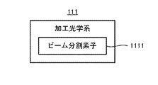
- FIG. 23 is a block diagram showing the configuration of the processing optical system provided in the processing system in the first modified example.
- FIG. 24 is a plan view showing a plurality of machining lights with which turbine blades are irradiated.
- FIG. 25 is a plan view showing a plurality of machining lights with which turbine blades are irradiated.
- FIG. 24 is a plan view showing a plurality of machining lights with which turbine blades are irradiated.
- FIG. 26 is a plan view showing a plurality of machining lights with which turbine blades are irradiated.
- FIG. 27 is a plan view showing a plurality of machining lights with which turbine blades are irradiated.
- FIG. 28 schematically shows a processing system for post-processing.
- FIG. 29 is a block diagram showing the configuration of the processing system in the second modified example.
- FIG. 30 is a cross-sectional view showing a modification of the riblet structure.
- each of the X-axis direction and the Y-axis direction is the horizontal direction (that is, a predetermined direction in the horizontal plane), and the Z-axis direction is the vertical direction (that is, the direction perpendicular to the horizontal plane). and substantially in the vertical direction).
- the directions of rotation (in other words, tilt directions) about the X-, Y-, and Z-axes are referred to as the .theta.X direction, the .theta.Y direction, and the .theta.Z direction, respectively.
- the Z-axis direction may be the direction of gravity.
- the XY plane may be set horizontally.
- FIG. 1 is a cross-sectional view schematically showing the structure of the processing system SYS of this embodiment.
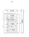
- FIG. 2 is a system configuration diagram showing the system configuration of the machining system SYS of this embodiment.
- the processing system SYS includes a processing device 1, a processing light source 2, and a control device 3. At least part of the processing device 1 is housed in the internal space of the housing 4 .
- the internal space of the housing 4 may or may not be purged with a purge gas such as nitrogen gas.
- the internal space of the housing 4 may or may not be evacuated.
- the processing device 1 does not have to be accommodated in the internal space of the housing 4 . That is, the processing system SYS does not have to include the housing 4 that accommodates the processing device 1 .
- the processing device 1 is capable of processing a workpiece W, which is an object to be processed (which may be called a base material).
- the workpiece W may be, for example, a metal, an alloy (for example, duralumin), a semiconductor (for example, silicon), a resin, or CFRP. (Carbon Fiber Reinforced Plastic), etc., paint (for example, a paint layer applied to a base material), glass, or any other material. It may be an object made of material.
- the surface of the work W may be coated with a film made of a material different from that of the work W.
- the surface of the film coated on the surface of the work W may be the surface to be processed by the processing device 1 .
- the processing apparatus 1 may be regarded as processing the work W (that is, processing the work W coated with a film).
- the processing device 1 irradiates the work W with the processing light EL in order to process the work W.
- the processing light EL may be any type of light as long as the work W can be processed by being irradiated with the work W.
- the processing light EL may be light of a different type from laser light.
- the wavelength of the processing light EL may be any wavelength as long as the work W can be processed by being irradiated with the work W.
- the processing light EL may be visible light or invisible light (for example, at least one of infrared light, ultraviolet light, extreme ultraviolet light, and the like).
- the processing light EL may include pulsed light (for example, pulsed light whose emission time is picoseconds or less). Alternatively, the processing light EL may not contain pulsed light. In other words, the processing light EL may be continuous light.
- the processing apparatus 1 may perform removal processing to remove a part of the work W by irradiating the work W with the processing light EL.
- the processing apparatus 1 forms a riblet structure RB on the surface of the work W by performing removal processing, which will be described in detail later with reference to FIG. 6 .
- the riblet structure RB may include a structure that can reduce the resistance of the surface of the workpiece W to fluid (particularly, at least one of frictional resistance and turbulent frictional resistance).
- the riblet structure RB may be formed in a workpiece W having members that are installed (in other words, located) in a fluid.
- the term "fluid" as used herein means a medium (for example, at least one of gas and liquid) flowing on the surface of the workpiece W.
- the medium may be called a fluid.
- the state in which the medium is stationary may mean the state in which the medium is not moving with respect to a predetermined reference object (for example, the ground surface).
- the work W is: It becomes easier to move relative to the fluid. Therefore, the resistance that hinders movement of the workpiece W against the fluid is reduced, leading to energy saving. That is, it becomes possible to manufacture the work W that is friendly to the environment.
- the riblet structure RB is formed on the turbine blade BL, which will be described later, the resistance that hinders the movement (typically, rotation) of the turbine blade BL is reduced. For example, it leads to energy saving of the turbine T). That is, it is possible to manufacture an environmentally friendly turbine blade BL (turbine T).
- a turbine blade BL is given as an example of the workpiece W on which the riblet structure RB is formed.
- the processing device 1 may form the riblet structure RB on the surface of the turbine blade BL by processing the turbine blade BL.
- a turbine blade BL is a member used in the turbine T. As shown in FIG. A member may also be referred to as a part.
- the turbine blades BL are at least part of the turbine T.
- the turbine blade BL is a blade-shaped member that constitutes the vanes of the turbine T installed in the fluid. Therefore, the turbine blade BL may be referred to as a blade member.
- FIGS. 3 and 4 An example of a turbine T is shown in FIGS. 3 and 4.
- 3 is a perspective view showing the appearance of the turbine T.
- FIG. FIG. 4 is a perspective view showing the appearance of the turbine blade BL.
- the turbine T has a plurality of turbine blades BL.
- Turbine blade BL includes a shank 91 and a blade body 92 coupled to shank 91 and extending radially outward of turbine T from shank 91 .
- At least one of the shank 91 and the blade body 92 may be constructed from a single piece of metal.
- At least one of the shank 91 and the blade body 92 may be composed of multiple metals.
- At least one of the shank 91 and the blade body 92 may be manufactured by existing manufacturing methods (eg, manufacturing methods using at least one of casting, forging, additional processing, removal processing, and machining).
- the shank 91 and blade body 92 may be integrally manufactured.
- the separately manufactured shank 91 and blade body 92 may be joined by existing joining methods (eg, joining methods using at least one of welding, brazing, gluing, etc.).
- the plurality of shanks 91 included in each of the plurality of turbine blades BL may be coupled with each other.
- a plurality of coupled shanks 91 may constitute at least part of the rotatable rotor RT.
- the rotor RT and turbine blades BL may be integrally formed.
- the blade body 92 extends radially outward of the turbine T from the platform 911 of the shank 91 .
- Platforms 911 include a pressure side platform 9111 and a suction side platform 9112 .
- the blade body 92 includes a pressure surface 921 , a suction surface 922 facing away from the pressure surface 921 , a root portion 923 coupled to the shank 91 , and a tip constituting an end opposite to the root portion 923 . 924.
- the blade body 92 further has a leading edge surface 925 located between the pressure surface 921 and the suction surface 922 and a trailing edge surface located between the pressure surface 921 and the suction surface 922 on the opposite side of the leading edge surface 925 . 926.
- At least one surface of pressure surface 921, suction surface 922, leading edge surface 925 and trailing edge surface 926 may include a curved surface.
- at least each surface of the pressure surface 921 and the suction surface 922 includes a curved surface.
- the turbine T is rotatable using the flow of fluid supplied to it.
- the turbine T is supplied with a fluid (eg, at least one of water, steam, air, and gas). Fluid supplied to the turbine T flows along the surface of each of the plurality of turbine blades BL. For this reason, the turbine blade BL is used in fluid. As a result, the kinetic energy of the fluid is converted into rotational energy of the turbine T by the plurality of turbine blades BL.
- a turbine T is at least one of a steam turbine using steam as a fluid and a gas turbine using gas as a fluid.
- Another example of such a turbine T is at least one of a hydraulic turbine using water as a fluid and a buoyancy turbine using air as a fluid.
- the turbine T may also generate a fluid flow through its rotation.
- the turbine T shown in FIGS. 3 and 4 includes axial-flow turbine blades BL. That is, the turbine T shown in FIGS. 3 and 4 is an axial turbine. However, turbine T may also be a radial turbine, as shown in FIG. In a radial turbine, the fluid enters the turbine blades BL parallel to the axis of rotation 120 of the turbine blade BL and crosses the axis of rotation 120 from the exit portion 160, as indicated by arrows F1 and F2 in FIG. flow in the direction
- the workpiece W is a turbine blade BL
- the workpiece W is not limited to the turbine blade BL. That is, the riblet structure RB may be formed on a workpiece W different from the turbine blade BL.
- Another example of the workpiece W on which the riblet structure RB is formed is any member that moves relatively to a medium (for example, fluid).
- the workpiece W may be at least part of a turbine vane. That is, in addition to or instead of the turbine blades BL forming the blade members which may be called moving blades, the turbine vanes forming the blade members which may be called stationary blades may be used as the workpiece W. .
- the workpiece W may be a member (for example, a member installed in a fluid) that is different from the blade members of the turbine W. That is, the workpiece W may be any member used in the turbine W (for example, a member placed in a fluid).
- the workpiece W may be the turbine T itself (for example, the turbine T shown in FIGS. 3 to 5) or at least a portion of the turbine T itself.
- the workpiece W may be a fan, impeller, propeller, or pump itself.
- the workpiece W may be at least part of a fan, impeller, propeller, or pump.
- the workpiece W may be a fan, an impeller, a propeller, or a member used in a pump (for example, a member placed in a fluid).
- the workpiece W may be at least a blade member of a fan, impeller, propeller, or pump propeller.
- a fan is a member (typically, a rotating body) that is used in a blower or the like and forms a gas flow.
- a propeller is, for example, a member (typically a rotating body) that converts the rotational force output from a prime mover, including at least one of an engine and a motor, into the propulsion force of a moving object, including at least one of an airplane and a ship. is.
- An impeller is, for example, a member used in a pump, and is a rotatable vane wheel so that the pump generates a force that pumps (or draws) fluid.
- the workpiece W may be at least part of a stationary splitter plate that is arranged around the impeller.
- the work W may be at least part of a housing (for example, an airframe or hull) of a moving body including at least one of an airplane and a ship.
- the workpiece W may be at least part of a wing portion (so-called wing) of a flying object such as an airplane.
- the work W may include a casing. That is, the riblet structure RB may be formed in at least part of the casing.
- the riblet structure RB serves as a wall member facing at least one of a housing space housing the turbine blades BL (that is, moving blades) and a passage through which fluid flows. It may be formed on at least a portion of the inner wall surface of the casing that functions.
- the riblet structure RB is at least the inner wall surface of the casing that functions as a wall member that faces at least one of the accommodation space that accommodates the impeller and the passage through which the fluid flows. It may be formed in a part.
- the riblet structure RB is at least one of a housing space for housing the fan, propeller, or pump and a passage through which a fluid (e.g., refrigerant) flows. It may be formed on at least a portion of the inner wall surface of the casing, functioning as one facing wall member.
- a fluid e.g., refrigerant
- the workpiece W may be a blade of a wind turbine used for wind power generation (that is, a blade). That is, the riblet structure RB may be formed on the blade of the wind turbine. In particular, the riblet structure RB may be formed in a windmill blade for obtaining clean energy (or natural energy or renewable energy) with low environmental impact. In this case, energy efficiency can be improved.
- the processing apparatus 1 may perform additional processing of adding a new structure to the work W by irradiating the work W with the processing light EL in addition to or instead of the removal processing.
- the processing apparatus 1 may form the above-described riblet structure RB on the surface of the workpiece W by performing additional processing.
- the processing apparatus 1 may perform machining for processing the workpiece W by bringing a tool into contact with the workpiece W in addition to or instead of at least one of the removal machining and the additional machining.
- the processing apparatus 1 may form the above-described riblet structure RB on the surface of the workpiece W by performing machining.
- the processing light EL is supplied from the processing light source 2 that generates the processing light EL to the processing device 1 via a light propagation member (for example, at least one of an optical fiber and a mirror) (not shown).
- the processing apparatus 1 irradiates a work W with processing light EL supplied from a processing light source 2 .
- the processing apparatus 1 includes a processing head 11, a head drive system 12, a stage 13, and a stage drive system 14.
- the machining head 1 irradiates the workpiece W with machining light EL from the machining light source 2 .
- the processing head 11 includes a processing optical system 111 .
- the processing head 11 irradiates the work W with the processing light EL through the processing optical system 111 .
- the processing optical system 111 may focus the processing light EL on the surface of the workpiece W, for example.
- the processing optical system 111 may, for example, control the optical properties of the processing light EL.
- Examples of the optical characteristics of the processing light EL include the intensity of the processing light EL, temporal changes in the intensity of the processing light EL, the condensing position of the processing light EL, the incident angle of the processing light EL with respect to the workpiece W, and the light of the processing optical system 111. At least one of the shape of the processing light EL in the optical plane intersecting the axis, the intensity distribution of the processing light EL in the optical plane, and the number of pulses of the processing light (when the processing light is pulsed light) can give.
- the head drive system 12 moves the processing head 11 along at least one of the X-axis direction, Y-axis direction and Z-axis direction. Note that the head drive system 12 moves the processing head 11 along at least one of the ⁇ X direction, the ⁇ Y direction, and the ⁇ Z direction in addition to or instead of at least one of the X-axis direction, the Y-axis direction, and the Z-axis direction. You may let When the processing head 11 moves, the positional relationship between the stage 13 (furthermore, the workpiece W placed on the stage 13) and the processing head 11 changes. Furthermore, when the positional relationship between the stage 13 and the work W and the processing head 11 changes, the irradiation position of the processing light EL on the work W changes.
- a workpiece W is placed on the stage 13 .
- the stage 13 does not have to hold the work W placed on the stage 13 . That is, the stage 13 does not need to apply a holding force for holding the work W placed on the stage 13 to the work W.
- the stage 13 may hold the work W placed on the stage 13 . That is, the stage 13 may apply a holding force to the work W placed on the stage 13 to hold the work W.
- the stage 13 may hold the work W by vacuum chucking and/or electrostatic chucking of the work W.
- a jig for holding the work W may hold the work W, and the stage 13 may hold the jig holding the work W.
- the stage drive system 14 moves the stage 13 under the control of the control device 3 . Specifically, the stage drive system 14 moves the stage 13 with respect to the processing head 11 .
- the stage drive system 14 may move the stage 13 along at least one of the X-axis direction, Y-axis direction, Z-axis direction, ⁇ X direction, ⁇ Y direction, and ⁇ Z direction under the control of the control device 3. good. It should be noted that moving the stage 13 along at least one of the ⁇ X direction, ⁇ Y direction and ⁇ Z direction corresponds to the X axis, Y axis and Z axis of the stage 13 (furthermore, the workpiece W placed on the stage 13).
- moving the stage 13 along at least one of the ⁇ X direction, ⁇ Y direction and ⁇ Z direction means rotating (or rotationally moving) the stage 13 around at least one of the X axis, Y axis and Z axis.
- rotating or rotationally moving the stage 13 around at least one of the X axis, Y axis and Z axis.
- the positional relationship between the stage 13 (furthermore, the workpiece W placed on the stage 13) and the processing head 11 changes. Furthermore, when the positional relationship between the stage 13 and the work W and the processing head 11 changes, the irradiation position of the processing light EL on the work W changes.
- the control device 3 controls the operation of the processing system SYS. For example, the control device 3 generates processing control information for processing the work W, and controls the processing device 1 based on the processing control information so that the work W is processed according to the generated processing control information. may That is, the control device 3 may control the machining of the workpiece W.
- the control device 3 may include, for example, an arithmetic device and a storage device.
- the computing device may include, for example, at least one of a CPU (Central Processing Unit) and a GPU (Graphics Processing Unit).
- the control device 3 functions as a device that controls the operation of the machining system SYS by the arithmetic device executing a computer program.
- This computer program is a computer program for causing the control device 3 (for example, arithmetic device) to perform (that is, execute) an operation to be performed by the control device 3, which will be described later. That is, this computer program is a computer program for causing the control device 3 to function so as to cause the machining system SYS to perform the operations described later.
- the computer program executed by the arithmetic device may be recorded in a storage device (that is, a recording medium) provided in the control device 3, or any storage that is built in the control device 3 or can be externally attached to the control device 3 It may be recorded on a medium (for example, hard disk or semiconductor memory). Alternatively, the computing device may download the computer program to be executed from a device external to the control device 3 via the network interface.
- a storage device that is, a recording medium
- the computing device may download the computer program to be executed from a device external to the control device 3 via the network interface.
- the control device 3 does not have to be provided inside the processing system SYS.
- the control device 3 may be provided as a server or the like outside the machining system SYS.
- the control device 3 and the processing system SYS may be connected by a wired and/or wireless network (or data bus and/or communication line).
- a wired network a network using a serial bus interface represented by at least one of IEEE1394, RS-232x, RS-422, RS-423, RS-485 and USB may be used.
- a network using a parallel bus interface may be used as the wired network.
- a network using an Ethernet (registered trademark) interface represented by at least one of 10BASE-T, 100BASE-TX, and 1000BASE-T may be used.
- a network using radio waves may be used as the wireless network.
- An example of a network using radio waves is a network conforming to IEEE802.1x (for example, at least one of wireless LAN and Bluetooth (registered trademark)).
- a network using infrared rays may be used as the wireless network.
- a network using optical communication may be used as the wireless network.
- the controller 3 and the machining system SYS may be configured to be able to transmit and receive various information via a network.
- control device 3 may be capable of transmitting information such as commands and control parameters to the processing system SYS via a network.
- the machining system SYS may include a receiving device that receives information such as commands and control parameters from the control device 3 via the network.
- a first control device that performs part of the processing performed by the control device 3 is provided inside the processing system SYS, while a second control device that performs another part of the processing performed by the control device 3 is provided.
- the control device may be provided outside the processing system SYS.
- a computing model that can be constructed by machine learning may be implemented in the control device 3 by the computing device executing a computer program.
- An example of an arithmetic model that can be constructed by machine learning is an arithmetic model that includes a neural network (so-called artificial intelligence (AI)).
- learning the computational model may include learning neural network parameters (eg, at least one of weights and biases).
- the control device 3 may control the operation of the machining system SYS using a computational model. That is, the operation of controlling the operation of the machining system SYS may include the operation of controlling the operation of the machining system SYS using the arithmetic model.
- control device 3 may be equipped with an arithmetic model that has already been constructed by off-line machine learning using teacher data. Further, the arithmetic model installed in the control device 3 may be updated by online machine learning on the control device 3 .
- control device 3 may use a computation model implemented in a device external to the control device 3 (that is, a device provided outside the machining system SYS). may be used to control the operation of the processing system SYS.
- Recording media for recording computer programs executed by the arithmetic unit include CD-ROMs, CD-Rs, CD-RWs, flexible disks, MOs, DVD-ROMs, DVD-RAMs, DVD-Rs, DVD+Rs, DVD- At least one of optical discs such as RW, DVD+RW and Blu-ray (registered trademark), magnetic media such as magnetic tapes, magneto-optical discs, semiconductor memories such as USB memories, and other arbitrary media capable of storing programs are used.
- the recording medium may include a device capable of recording a computer program (for example, a general-purpose device or a dedicated device in which a computer program is implemented in at least one form of software, firmware, etc., in an executable state).
- each process and function included in the computer program may be realized by a logical processing block realized in the control device 3 by the control device 3 (that is, computer) executing the computer program, It may be implemented by hardware such as a predetermined gate array (FPGA, ASIC) provided in the control device 3, or a mixture of logical processing blocks and partial hardware modules that implement some elements of hardware. It can be implemented in the form of
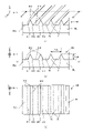
- FIG. 6(a) is a perspective view showing the riblet structure RB
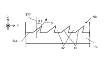
- FIG. 6(b) is a cross-sectional view showing the riblet structure RB (cross-sectional view taken along line VI-VI' in FIG. 6(a)).
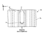
- (c) is a top view showing the riblet structure RB.
- a riblet structure RB formed on a turbine blade BL, which is a specific example of the workpiece W, will be described below.
- the riblet structure RB formed on the workpiece W different from the turbine blade BL may also have the structure described below.
- the riblet structure RB has convex structures 81 extending along the first direction along the surface of the turbine blade BL.
- a plurality of structures may be arranged along a second direction that extends along and intersects the first direction. That is, the riblet structure RB may include a structure in which the convex structures 81 formed to extend along the first direction are arranged along the second direction.
- the riblet structure RB includes a structure in which a plurality of convex structures 81 extending along the X-axis direction are arranged along the Y-axis direction. .
- the convex structure 81 is a structure projecting along a direction intersecting both the direction in which the convex structure 81 extends and the direction in which the convex structure 81 is arranged.
- the direction in which the convex structure 81 extends may typically mean the longitudinal direction of the convex structure 81 .
- the convex structure 81 is a structure protruding from the surface of the turbine blade BL. In the examples shown in FIGS. 6A to 6C, the convex structure 81 is a structure projecting along the Z-axis direction.
- the convex structure 81 may include a protrusion-shaped structure that protrudes from the surface of the turbine blade BL.
- the convex structure 81 may include a convex structure that is convex with respect to the surface of the turbine blade BL.
- the convex structure 81 may include a mountain-shaped structure forming a mountain on the surface of the turbine blade BL.
- a groove structure 82 that is recessed compared to the surroundings is formed between adjacent convex structures 81 .
- the riblet structure RB is configured such that the groove structure 82 extending along a first direction along the surface of the turbine blade BL extends in a second direction along the surface of the turbine blade BL and intersecting the first direction. may include structures arranged multiple times along the . That is, the riblet structure RB may include a structure in which the groove structures 82 formed so as to extend along the first direction are arranged along the second direction.
- the riblet structure RB includes a structure in which a plurality of groove structures 82 extending along the X-axis direction are arranged along the Y-axis direction. Note that the groove structure 82 may also be referred to as a groove-like structure.
- the convex structure 81 may be regarded as a structure protruding from the groove structure 82 .
- the convex structure 81 may be regarded as a structure that forms at least one of a protrusion-shaped structure, a convex-shaped structure, and a mountain-shaped structure between two adjacent groove structures 82 .
- the groove structure 82 may be regarded as a structure recessed from the convex structure 81 .
- the groove structure 82 may be regarded as a structure that forms a groove-shaped structure between two adjacent convex structures 81 .
- the groove structure 82 may also be referred to as a groove-like structure.
- the plurality of convex structures 81 may be formed so that the plurality of convex structures 81 are regularly arranged.
- the plurality of convex structures 81 may be formed so that the plurality of convex structures 81 are arranged at equal pitches.
- the plurality of convex structures 81 may be formed such that a plurality of structural groups each including at least two convex structures 81 are arranged at equal pitches. At least two convex structures 81 are arranged regularly according to a first rule on the first portion of the surface of the turbine blade BL, and at least two convex structures 81 are arranged on the second portion of the surface of the turbine blade BL.
- the two convex structures 81 may be formed so as to be regularly arranged according to the same first rule.
- the plurality of convex structures 81 are arranged regularly according to a first rule in a first portion of the surface of the turbine blade BL, while in a second portion of the surface of the turbine blade BL
- At least two convex structures 81 may be formed so as to be regularly arranged according to a second rule different from the first rule. Since the convex structures 81 and the groove structures 82 are alternately formed, the state in which the plurality of convex structures 81 are regularly arranged is equivalent to the state in which the plurality of groove structures 82 are regularly arranged. can be considered to be
- the direction in which the convex structure 81 extends may be the direction along the streamline on the surface of the turbine blade BL. That is, the convex structure 81 may extend along the streamline on the surface of the turbine blade BL.
- the streamline of the turbine blade BL may mean a curve whose tangent is the velocity vector of the flow field on the surface of the turbine blade BL.
- a convex structure 81 extending in a curved shape along the streamline may be formed on the surface of the turbine blade BL.
- the surface of the turbine blade BL is divided into a plurality of surface regions, and in each surface region, a convex structure linearly extending along the direction in which the straight line obtained by averaging the streamlines of each surface region extends.
- the processing system SYS may form the riblet structure RB by forming the convex structures 81 extending in a curved line, or may form the riblet structure RB by forming the convex structures 81 extending in a straight line. may The same can be said for the groove structure 82 formed between the two convex structures 81 .
- the convex structure 81 has, for example, a pair of side surfaces 811 and 812 facing opposite to each other.
- a state in which one surface and another surface face opposite sides refers to, for example, a state in which one surface faces one side of an axis that intersects the one surface and the other surface. and the other face faces the other side along the same axis (that is, the opposite side to the one side).
- the convex structure 81 has a side surface 811 facing the ⁇ Y side and a side surface 812 facing the +Y side.
- Each of the pair of side surfaces 811 and 812 is flat. However, at least one of the pair of side surfaces 811 and 812 may include curved surfaces.
- the pair of side surfaces 811 and 812 may be non-parallel to each other.
- the pair of side surfaces 811 and 812 of the convex structure 81 are connected via one end thereof (upper end on the +Z side in the examples shown in FIGS. 6(a) to 6(c)).
- a portion where the pair of side surfaces 811 and 812 of the convex structure 81 are connected constitutes a corner portion 813 of the convex structure 81 .
- the corner 813 of the convex structure 81 may constitute the vertex of the convex structure 81 .
- a corner 813 of the convex structure 81 may form a boundary between a pair of side surfaces 811 and 812 of the convex structure 81 .
- the pair of side surfaces 811 and 812 may be considered to be connected via corners 813 of the convex structure 81 .
- the pair of side surfaces 811 and 812 are connected so that the upper end of the side surface 811 and the upper end of the side surface 812 are in contact with each other.
- the cross-sectional shape of the convex structure 81 including the Z-axis may be triangular.
- the cross-sectional shape of the convex structure 81 including the Z-axis may be a symmetrical triangular shape or an asymmetrical triangular shape.
- the cross-sectional shape of the convex structure 81 including the Z-axis may have any shape other than the triangular shape.
- the corner portion 813 may include a curved surface.
- the pair of side surfaces 811 and 812 are non-parallel to each other means that the virtual surface (typically a plane) including the side surface 811 and the virtual surface (typically a plane) including the side surface 812 intersect each other. may contain At this time, the virtual plane including the side surface 811 and the virtual plane including the side surface 812 may be the approximate plane of the side surface 811 and the approximate plane of the side surface 812, respectively.
- each of the pair of side surfaces 811 and 812 is in the direction in which the convex structure 81 protrudes (Fig. 6(a) to Fig. 6(c)). ), it may be inclined with respect to the Z-axis direction).
- each of the sides 811 and 821 may be referred to as a ramp.
- the pair of side surfaces 811 and 812 may be parallel to each other.
- the side surface 811 of one convex structure 81 and the side surface 812 of another convex structure 81 adjacent to the one convex structure 81 along the direction in which the convex structures 81 are arranged are The connection may be made via a boundary portion 814 that connects the other end portion (lower end portion on the ⁇ Z side in the examples shown in FIGS. 6A to 6C).
- the side surfaces 811 and 812 provided by two adjacent convex structures 81 and facing each other are connected via a boundary portion 814 forming a boundary between the two adjacent convex structures 81. good.
- boundary 814 includes surfaces that intersect each of side surfaces 811 and 812 to which boundary 814 connects.
- the groove structure 82 is formed by the boundary portion 814 and the side surfaces 811 and 812 to which the boundary portion 814 connects.
- the boundary portion 814 may be a plane.
- the cross-sectional shape of the groove structure 82 including the Z-axis is trapezoidal.
- the shape of the cross section containing the Z-axis of the groove structure 82 may have any shape different from the trapezoidal shape.
- the boundary portion 814 may include a curved surface, as will be described in detail later.
- the side surface 811 of one convex structure 81 and the side surface 812 of another convex structure 81 may be connected without intervening a boundary portion 814 including a surface.
- the side surface 811 of one convex structure 81 and the side surface 812 of the other convex structure 81 are the other ends (-Z (lower end of the side) may be in contact with each other.
- a portion where the other end of the side surface 811 of one convex structure 81 and the other end of the side surface 812 of the other convex structure 81 are connected may be referred to as a boundary portion 814 .
- At least one height H_rb of the plurality of convex structures 81 may be set to a height determined according to the pitch P_rb of the convex structures 81 .
- the height H_rb of at least one of the plurality of convex structures 81 may be less than or equal to the pitch P_rb of the convex structures 81 .
- the height H_rb of at least one of the plurality of convex structures 81 may be half or less of the pitch P_rb of the convex structures 81 .
- the pitch P_rb of the convex structures 81 may be greater than 5 micrometers and less than 200 micrometers.
- the pitch P_rb of the convex structure 81 may satisfy the first pitch condition of "5 micrometers ⁇ P_rb ⁇ 200 micrometers".
- the height H_rb of at least one of the plurality of convex structures 81 may be greater than 5 micrometers and less than 100 micrometers.
- At least one height H_rb of the plurality of convex structures 81 may satisfy a first height condition of "2.5 micrometers ⁇ H_rb ⁇ 100 micrometers". That is, the riblet structure RB may satisfy at least one of the first pitch condition and the first height condition.
- the lower limit of the height H_rb of at least one of the plurality of convex structures 81 (for example, the height under conditions where the pitch P_rb is the lower limit of 5 micrometers)
- 2.0 micrometers may be used instead of 2.5 micrometers.
- the riblet structure RB that satisfies such a first pitch condition can more appropriately reduce the resistance to fluid on the surface of the turbine blade BL compared to the riblet structure RB that does not satisfy the first pitch condition. .
- the resistance to the fluid on the surface of the turbine blade BL can be reduced compared to the case where the riblet structure RB is not formed in the first place.
- the riblet structure RB that satisfies such a first height condition provides a better resistance to fluid on the surface of the turbine blade BL than the riblet structure RB that does not satisfy the first height condition. can be reduced.
- the resistance to the fluid on the surface of the turbine blade BL can be reduced compared to the case where the riblet structure RB is not formed in the first place.
- the height H_rb of the convex structure 81 in this embodiment is the height of the convex structure in the direction in which the convex structure 81 protrudes (in the example shown in FIGS. 6A to 6C, the Z-axis direction). It may mean the size of body 81 .
- the height H_rb of the protruding structure 81 may mean the distance from the lower end of the protruding structure 81 to the upper end of the protruding structure 81 in the direction in which the protruding structure 81 protrudes.
- the height H_rb of the convex structure 81 is the distance from the boundary portion 814 connected to the lower end of the convex structure 81 to the corner portion 813 corresponding to the vertex of the convex structure 81 in the direction in which the convex structure 81 protrudes. It can also mean distance. It should be noted that the height of the convex structure 81 may be considered substantially equivalent to the depth of the groove structure 82 .
- the pitch P_rb of the convex structures 81 in this embodiment is between the same corresponding portions (for example, vertices) of two adjacent convex structures 81 in the direction intersecting the direction in which the convex structures 81 extend. may mean the distance of In the examples shown in FIGS.
- the pitch p_rb of the convex structures 81 means the distance between the vertices of two adjacent convex structures 81 in the Y-axis direction. good too. Since the convex structures 81 and the groove structures 82 are alternately formed in the direction intersecting the extending direction of the convex structures 81, the pitch P_rb of the convex structures 81 is equal to the pitch of the groove structures 82. can be considered equivalent to The pitch of the groove structures 82 may mean the distance between the same corresponding portions of two groove structures 82 adjacent in the direction crossing the direction in which the groove structures 82 extend. In the examples shown in FIGS. 6(a) to 6(c), the pitch of the groove structures 82 may mean the distance between the same corresponding portions of the two groove structures 82 adjacent in the Y-axis direction. .
- the processing system SYS of the present embodiment forms the riblet structure RB by performing removal processing. For this reason, the processing system SYS performs removal processing on a surface portion of the surface of the turbine blade BL on which the riblet structure RB is formed (hereinafter referred to as “riblet structure surface BLs”), thereby removing the riblet structure RB.
- the processing system SYS may form the riblet structure RB by performing removal processing to remove a portion of the turbine blade BL where the groove structure 82 is formed.
- the processing system SYS may form the riblet structure RB by performing removal processing to remove a portion of the turbine blade BL so as to leave a portion of the turbine blade BL on which the convex structure 81 is formed. good.
- the processing system SYS may irradiate the turbine blade BL with the processing light EL so that the portion of the riblet structure surface BLs of the turbine blade BL where the groove structure 82 is formed is irradiated with the processing light EL.
- the processing system SYS moves the target irradiation area EA (see FIG.
- the riblet structure surface BLs on which the riblet structure RB is formed may function as a surface capable of reducing the fluid resistance of the turbine blade BL.
- the processing system SYS forms the riblet structure RB on the turbine blade BL. That is, the turbine blade BL on which the riblet structure RB is formed is manufactured by the processing system SYS. In other words, the turbine blade BL having the riblet structure RB formed thereon is manufactured by machining the turbine blade BL with the machining system SYS.
- the turbine blade BL formed with the riblet structure RB may be manufactured by a method different from the method by which the processing system SYS processes the turbine blade BL. That is, the riblet structure RB may be formed by a method different from the method by which the processing system SYS processes the turbine blade BL.
- the turbine blade BL formed with the riblet structure RB may be manufactured using a mold (for example, at least one of a mold and a casting mold) ML. That is, the turbine blade BL on which the riblet structure RB is formed may be manufactured using a molding method in which a molten material is poured into the mold ML, and then the molten material is cooled and solidified. In this case, the turbine blade BL on which the riblet structure RB is formed may be regarded as a molded product molded using the mold ML. The turbine blade BL on which the riblet structure RB is formed may be regarded as an injection molded product that is injection molded using the mold ML.
- the mold ML may function as a mold for molding (for example, injection molding) the turbine blade BL having the riblet structure RB formed thereon with a meltable material.
- the mold ML may be made of any material as long as the turbine blade BL can be manufactured using the mold ML.
- a mold made of zirconia (zirconia ceramics) a mold made of pre-hardened steel, a mold made of as-rolled steel, and a mold made of stainless steel may be used as the mold ML.
- a mold made of any metal may be used as the mold ML.
- a mold made of any material different from metal may be used as the mold ML.
- FIG. 7 A specific example of the mold ML used to manufacture the turbine blade BL having the riblet structure RB will be described below.
- the riblet structure surface BLs forming the pressure surface 921 (see FIG. 4) and the riblet structure surface BLs forming the suction surface 922 (see FIG. 4) are defined.
- a mold ML for manufacturing the turbine blade BL comprising is described. 7 corresponds to the IV-IV' sectional view of FIG.
- the riblet structure surface BLs forming the pressure surface 921 will be referred to as the riblet structure surface BLs1
- the riblet structure surface BLs forming the suction surface 922 will be referred to as the riblet structure surface BLs2.
- a turbine blade BL (or any workpiece W described above) different from the turbine blade BL having the riblet structure surfaces BLs1 and BLs2 may be manufactured by a mold ML having features similar to the mold ML described below. good.
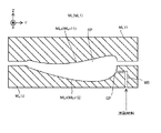
- FIG. 8 is a cross-sectional view showing the structure of the type ML1.
- the mold ML1 includes a mold ML11, which may be called a core or male mold, and a mold ML12, which may be called a cavity or female mold. That is, in the example shown in FIG. 8, the mold ML1 is a two-plate type mold. However, the mold ML1 may be a three-plate type, or a multi-plate type mold including four or more molds.
- the mold ML1 may be an assembly mold (that is, a mold divided into a plurality of mold parts and a mold that combines the plurality of mold parts). Alternatively, mold ML1 may be a roller-based mold as described in US2016/325818. Alternatively, the mold ML1 may be a stamped mold.
- Each of the molds ML11 and ML12 has molding surfaces MLs.
- the molding surface MLs of the mold ML11 will be referred to as molding surface MLs11
- the molding surface MLs of the mold ML12 will be referred to as molding surface MLs12, as required.
- both are collectively referred to as the molding surface MLs.
- the molding surface MLs is the surface that is in contact with the material that is poured into the mold ML1 to manufacture the turbine blade BL. Therefore, the space surrounded by the molding surfaces MLs becomes a molding space SP supplied with material to be poured into the mold ML1 for manufacturing the turbine blade BL.
- the material that is poured into the mold ML1 is typically a fluid material.
- the material that is poured into the mold ML1 may be a molten material (eg, molten metal) or a softened material.
- the molding space SP has a shape corresponding to the shape of the turbine blade BL. Therefore, in the example shown in FIG. 8, the mold ML1 may be regarded as a mold type mold.
- the mold ML is penetrated into the molding space SP.
- a molten material is supplied via a material supply path MS (for example, at least one of a sprue, a gate and a runner) leading to the molding space SP.
- the molten material is then cooled. As a result, the molten material solidifies. Therefore, the fluidity of the material is lowered.
- the molds ML11 and ML12 are separated, and the solidified material is taken out as the turbine blade BL from the molding space SP.
- a molding structure MB for forming (that is, molding) the riblet structure RB may be formed on the molding surface MLs.
- the molding structure MB may be formed on a surface portion of the molding surface MLs corresponding to the riblet structure surface BLs. That is, the molding structure MB may be formed on the surface portion of the molding surface MLs for molding the riblet structure surface BLs.
- the molding surface MLs11 corresponds to the riblet structure surface BLs1 forming the pressure surface 921
- the molding surface MLs12 corresponds to the riblet structure surface BLs2 forming the suction surface 922.
- FIGS. 9(a) and 9(b) FIG. 9(a) is a perspective view showing the molding structure MB
- FIG. 9(b) is a cross-sectional view showing the molding structure MB.
- the molded structure MB is a structure complementary to the riblet structure RB.
- the convex structure 71 extending along the fourth direction along the molding surface MLs extends in the fifth direction along the molding surface MLs and intersects the fourth direction.
- the molding structure MB includes a structure in which a plurality of convex structures 71 extending along the X-axis direction are arranged along the Y-axis direction. .
- the convex structure 71 is a structure protruding along a direction crossing both the extending direction of the convex structure 71 and the arrangement direction of the convex structure 71 .
- the convex structure 71 is a structure protruding from the surface of the mold ML11 or ML12.
- the convex structure 71 is a structure projecting along the Z-axis direction.
- the convex structure 71 may include a protrusion-shaped structure that protrudes from the surface of the mold ML11 or ML12.
- the convex structure 71 may include a convex structure that is convex with respect to the surface of the mold ML11 or ML12.
- the convex structure 71 may include a mountain-shaped structure forming a mountain on the surface of the mold ML11 or ML12.
- the molding structure MB has a plurality of groove structures 72 extending along the fourth direction along the molding surface MLs along the fifth direction that extends along the molding surface MLs and intersects the fourth direction. It may contain ordered structures. That is, the molding structure MB may include a structure in which the groove structures 72 formed so as to extend along the fourth direction are arranged along the fifth direction. In the example shown in FIGS. 9A and 9B, the molding structure MB includes a structure in which a plurality of groove structures 72 extending along the X-axis direction are arranged along the Y-axis direction.
- the convex structure 71 may be regarded as a structure protruding from the groove structure 72 .
- the convex structure 71 may be regarded as a structure that forms at least one of a protrusion-shaped structure, a convex-shaped structure, and a mountain-shaped structure between two adjacent groove structures 72 .
- the groove structure 72 may be regarded as a structure recessed from the convex structure 71 .
- the groove structure 72 may be regarded as a structure that forms a groove-shaped structure between two adjacent convex structures 71 .
- the groove structure 72 may also be referred to as a groove-like structure.
- the plurality of convex structures 71 may be formed so that the plurality of convex structures 71 are regularly arranged.
- the plurality of convex structures 71 may be formed so that the plurality of convex structures 71 are arranged at equal pitches.
- the plurality of convex structures 71 may be formed such that a plurality of structures including at least two convex structures 71 are arranged at equal pitches.
- at least two convex structures 71 are arranged regularly according to the third rule on the first portion of the molding surface MLs, and at least two convex structures are arranged on the second portion of the molding surface MLs.
- the bodies 71 may be formed to line up regularly according to the same third rule.
- the plurality of convex structures 71 are arranged regularly according to the third rule in the first portion of the molding surface MLs, while at least two convex structures 71 are arranged in the second portion of the molding surface MLs.
- the shaped structures 71 may be formed so as to be regularly arranged according to a fourth rule different from the third rule. Since the convex structures 71 and the groove structures 72 are alternately formed, the state in which the plurality of convex structures 71 are regularly arranged is equivalent to the state in which the plurality of groove structures 72 are regularly arranged. can be considered to be
- the material that has entered the groove structure 72 forms a convex structure 81 that constitutes the riblet structure RB. That is, the material that has entered the plurality of groove structures 72 forms the plurality of convex structures 81 that constitute the riblet structure RB. Therefore, the groove structure 72 forming the forming structure MB is a structure for forming the convex structure 81 forming the riblet structure RB. Therefore, as shown in FIG. 10, which is a cross-sectional view showing the relationship between the riblet structure RB and the molded structure MB, the shape (eg, cross-sectional shape) of the groove structure 72 is the same as the shape (eg, cross-sectional shape) of the convex structure 81. shape).
- the convex structures 71 forming the forming structure MB are structures for forming the groove structures 82 forming the riblet structure RB. Therefore, as shown in FIG. 10, the shape (eg, cross-sectional shape) of the protruding structure 71 is complementary to the shape (eg, cross-sectional shape) of the groove structure 82 .
- the riblet structure surface BLs of the turbine blade BL is shaped by the shaping structure MB. That is, the riblet structure surface BLs of the turbine blade BL is shaped by the convex structure 71 and the groove structure 72 that constitute the shaping structure MB.
- FIGS. 9A and 9B again, the convex structure 71 complementary to the groove structure 82 and the groove structure 72 complementary to the convex structure 81 will be further described. proceed with the explanation.
- the convex structure 71 has, for example, a pair of side surfaces 711 and 712 facing opposite to each other.
- the convex structure 71 has a side surface 711 facing the ⁇ Y side and a side surface 712 facing the +Y side.
- Each of the pair of side surfaces 711 and 712 is flat. However, at least one of the pair of side surfaces 711 and 712 may include a curved surface.
- the pair of side surfaces 711 and 712 may be non-parallel to each other.
- the pair of side surfaces 711 and 712 of the convex structure 71 are connected via one end thereof (upper end on the +Z side in the examples shown in FIGS. 9A to 9B).
- a portion where the pair of side surfaces 711 and 712 of the convex structure 71 are connected constitutes a corner portion 713 of the convex structure 71 .
- a corner portion 713 of the convex structure 71 may constitute a boundary portion between a pair of side surfaces 711 and 712 of the convex structure 71 .
- the pair of side surfaces 711 and 712 may be considered to be connected via corners 713 of the convex structure 71 .
- the corner portion 713 is a structure for forming a boundary portion 814 of the riblet structure RB (that is, a boundary portion 814 that is a plane connecting two adjacent convex structures 81). Therefore, in the example shown in FIGS. 9(a) to 9(b), the corner portion 713 includes a flat surface.
- the cross-sectional shape of the convex structure 71 including the Z-axis may be trapezoidal.
- the cross-sectional shape of the convex structure 71 including the Z-axis may have any shape different from the trapezoidal shape.
- the corner portion 713 may include a curved surface.
- the fact that the pair of side surfaces 711 and 712 are non-parallel to each other means that the virtual surface (typically a plane) including the side surface 711 and the virtual surface (typically a plane) including the side surface 712 intersect each other. may contain At this time, the virtual plane including the side surface 711 and the virtual plane including the side surface 712 may be the approximate plane of the side surface 711 and the approximate plane of the side surface 712, respectively.
- each of the pair of side surfaces 711 and 712 is in the direction in which the convex structure 71 protrudes (Fig. 9(a) to Fig. 9(b)). ), it may be inclined with respect to the Z-axis direction).
- each of the sides 711 and 821 may be referred to as a ramp.
- the pair of side surfaces 711 and 712 may be parallel to each other.
- the side surface 711 of one convex structure 71 and the side surface 712 of another convex structure 71 adjacent to the one convex structure 71 along the direction in which the convex structures 71 are arranged are It may be connected via the other end (in the example shown in FIGS. 9(a) to 9(c), the lower end on the ⁇ Z side).
- the side surfaces 711 and 712 provided by the two adjacent convex structures 71 and facing each other are connected via the boundary portion 714 forming the boundary between the two adjacent convex structures 71.
- the boundary portion 714 is a structure for forming the corner portion 813 of the riblet structure RB (that is, the vertex of the convex structure 81). Therefore, in the examples shown in FIGS.
- the side surfaces 711 and 712 of two adjacent convex structures 71 are directly connected, and the two adjacent convex structures 71 are connected to each other.
- a boundary portion 714 is a portion where the side surfaces 711 and 712 of the convex structure 71 are directly connected.
- the cross-sectional shape of the groove structure 72 including the Z-axis is triangular.
- the shape of the cross section containing the Z-axis of the groove structure 72 may have any shape different from the triangular shape.
- boundary 714 may include a plane.
- the cross-sectional shape of the groove structure 72 including the Z-axis may be trapezoidal.
- boundary 714 may include a curved surface, as will be discussed in greater detail below.
- the convex structure 71 is a structure for forming the groove structure 82 described above, the height H_mb of at least one of the plurality of convex structures 71 is equal to the depth of at least one of the plurality of groove structures 82 ( That is, it may be the same as the height H_rb) of at least one of the plurality of convex structures 81 . Also, the pitch P_mb of the convex structure 71 may be the same as the pitch of the groove structure 82 (that is, the pitch P_rb of the convex structure 71).
- the height H_mb of at least one of the plurality of convex structures 71 is set to a height determined according to the pitch P_mb of the convex structures 71. good too.
- the height H_mb of at least one of the plurality of convex structures 71 may be less than or equal to the pitch P_mb of the convex structures 71 .
- the height H_mb of at least one of the plurality of convex structures 71 may be half or less of the pitch P_nb of the convex structures 71 .
- the pitch P_mb of the convex structures 71 may be greater than 5 micrometers and less than 200 micrometers. That is, the pitch P_mb of the convex structure 71 may satisfy the second pitch condition of "5 micrometers ⁇ P_mb ⁇ 200 micrometers".
- the height H_mb of at least one of the plurality of convex structures 71 may be greater than 2.5 micrometers and less than 100 micrometers.
- At least one height H_mb of the plurality of convex structures 71 may satisfy a second height condition of "2.5 micrometers ⁇ H_mb ⁇ 100 micrometers". That is, the forming structure MB may satisfy at least one of the second pitch condition and the second height condition.
- the pitch of the groove structure 82 formed by the molding structure MB is It ranges from 10 microns to 200 microns.
- the pitch P_rb of the convex structures 81 and the pitch of the groove structures 82 are substantially equal. Therefore, when the convex structures 71 satisfy the second pitch condition, the pitch P_rb of the convex structures 81 of the riblet structure RB is in the range from 10 micrometers to 200 micrometers.
- the pitch P_rb of the convex structure 81 satisfies the first pitch condition of "5 micrometers ⁇ P_rb ⁇ 200 micrometers".
- the riblet structure RB can more appropriately reduce the resistance to fluid on the surface of the turbine blade BL.
- the groove formed by the molding structure MB The depth of structures 82 ranges from 5 microns to 100 microns.
- the height H_rb of the convex structure 81 of the riblet structure RB ranges from 5 micrometers to 100 micrometers.
- the height H_rb of the convex structure 81 satisfies the first height condition of "5 micrometers ⁇ H_rb ⁇ 100 micrometers".
- the riblet structure RB can more appropriately reduce the resistance to fluid on the surface of the turbine blade BL.
- the height H_mb of the convex structure 71 in this embodiment is the height of the convex structure in the direction in which the convex structure 71 protrudes (in the example shown in FIGS. 9A and 9B, the Z-axis direction). It may mean the size of the body 71 .
- the height H_mb of the protruding structure 71 may mean the distance from the lower end of the protruding structure 71 to the upper end of the protruding structure 71 in the direction in which the protruding structure 71 protrudes.
- the height H_mb of the convex structure 71 is from the boundary portion 714 connected to the lower end portion of the convex structure 71 to the corner portion 713 forming the upper end portion of the convex structure 71 in the direction in which the convex structure 71 protrudes. may mean the distance of It should be noted that the height of the convex structure 71 may be considered substantially equivalent to the depth of the groove structure 72 .
- the pitch P_mb of the convex structures 71 in this embodiment means the distance between the same corresponding parts of two adjacent convex structures 71 in the direction intersecting the direction in which the convex structures 71 extend. may be In the examples shown in FIGS.
- the pitch p_mb of the convex structures 71 means the distance between the vertices of two adjacent convex structures 71 in the Y-axis direction. good too. Since the convex structures 71 and the groove structures 72 are alternately formed in the direction intersecting the extending direction of the convex structures 71, the pitch P_mb of the convex structures 71 is equal to the pitch of the groove structures 72. can be considered equivalent to The pitch of the groove structures 72 may mean the distance between the same corresponding portions of two groove structures 72 adjacent in the direction crossing the direction in which the groove structures 72 extend. In the examples shown in FIGS. 9(a) and 9(b), the pitch of the groove structures 72 may mean the distance between the same corresponding portions of two adjacent groove structures 72 in the Y-axis direction. .
- the molding structure MB formed on the molding surface MLs may be formed by the processing system SYS. That is, the processing system SYS may form the molding structure MB on the molding surface MLs by irradiating the molding surface MLs with the processing light EL. The processing system SYS may form the molding structure MB on the molding surface MLs by performing removal processing on the molding surface MLs. Alternatively, the molding structure MB formed on the molding surface MLs may be formed by a device different from the processing system SYS. Note that the molds ML11 and ML12 before forming the molding structure MB may be manufactured by a method different from optical processing. As an example, the molds ML11 and ML12 before forming the molding structure MB may be manufactured by a method using at least one of cutting, casting, electrical discharge machining, and the like.
- the material supply port (so-called gate port) GP (see FIG. 8) for supplying the molten material to the molding space SP is formed according to the molding structure MB. It may be formed at a fixed position.
- the material supply port GP is typically an opening formed in the molding surface MLs by the material supply path MS.
- the material supply port GP may be formed at a position determined according to the extending direction of the convex structure 71 that constitutes the molding structure MB.
- the material supply port GP may be formed at a position determined according to the extending direction of the groove structure 72 forming the molding structure MB.
- the material supply port GP is formed at a position where the material supply port GP can supply the molten material along the direction in which at least one of the convex structure 71 and the groove structure 72 extends from the material supply port GP.
- the material supply port GP may be formed at a position where the direction in which the material is supplied from the material supply port GP can be aligned with the direction in which at least one of the convex structure 71 and the groove structure 72 extends.
- the material supply port GP is positioned so that the direction in which the material from the material supply port GP flows on the molding surface MLs can be aligned with the direction in which at least one of the convex structure 71 and the groove structure 72 extends. may be formed.
- the material supplied from the material supply port GP easily enters the groove structure 72, so that the turbine blade BL having the riblet structure RB can be properly manufactured.
- the molding surface MLs has, in addition to the material supply port GP, a gas discharge path for discharging the gas remaining in the molding space SP to the outside of the mold ML.
- a gas outlet AP leading to AE may be formed. That is, the molding surface MLs may be formed with a gas outlet AP for air vent.
- the gas outlet AP is formed in a boundary portion 714 forming the bottom portion of the groove structure 72.
- the gas outlet AP may be formed at other positions.
- the size along the longitudinal direction of the groove structure 72 of the air vent gas outlet AP may be, for example, 2 micrometers to 20 micrometers.
- the molds ML11 and ML12 are separated after the material supplied to the molding space SP is solidified. That is, the molds ML11 and ML12 are removed from the solidified material (that is, the turbine blade BL) in order to remove the solidified material as the turbine blade BL.
- the direction in which the molds ML11 and ML12 are removed from the turbine blade BL may be the direction based on the molding structure MB.
- the direction in which each of the molds ML11 and ML12 is removed from the turbine blade BL may be along the direction in which the plurality of convex structures 71 forming the forming structure MB extend.
- the direction in which each of the molds ML11 and ML12 is removed from the turbine blade BL may be along the average direction of the extending directions of the plurality of convex structures 71 forming the forming structure MB.
- Each of ML11 and ML12 can be removed. A portion of the material remaining in the groove structure 72 leads to chipping of a portion of the turbine blade BL composed of solidified material. Therefore, the possibility that a part of the turbine blade BL is chipped is reduced. Therefore, it is possible to manufacture a turbine blade BL with high shape accuracy. If the molds ML11 and ML12 cannot be removed from the turbine blade BL along the direction based on the forming structure MB, the turbine blade BL, the mold After moving at least one of ML11 and ML12, each of molds ML11 and ML12 may be removed from turbine blade BL along a direction based on forming structure MB.
- the direction in which each of the molds ML11 and ML12 is removed from the turbine blade BL may be along the direction in which the plurality of convex structures 71 constituting the forming structure MB protrude (that is, the height direction). good.
- the mold ML2 differs from the above-described mold ML1 in that at least one of the corner portion 713 and the boundary portion 714 includes a curved surface, in which each of the corner portion 713 and the boundary portion 714 does not have to include a curved surface. That is, in the mold ML2, at least one of the corner portion 713 and the boundary portion 714 is chamfered (particularly, R-chamfering and rounding processing).
- FIG. 11(a) is a perspective view showing a molding structure MB in which at least one of the corner portion 713 and the boundary portion 714 has a curved surface
- FIG. 10 is a cross-sectional view showing a forming structure MB including
- the corners 713 may include curved surfaces.
- 11A and 11B show an example in which the corner portion 713 includes a plane 7131, a curved surface 7132 connecting the plane 7131 and the side surface 711, and a curved surface 7133 connecting the plane 7131 and the side surface 712. ing. That is, FIGS. 11A and 11B show an example in which a part of the corner 713 is curved. However, the entire corner portion 713 may be curved.
- the corner portion 713 may include a curved surface connecting a pair of side surfaces 711 and 712 of the convex structure 71, similar to the boundary portion 714 described later.
- the corner portion 713 connects a pair of side surfaces 711 and 712 facing opposite sides as described above.
- this corner 713 includes a curved surface. Therefore, the corner portion 713 and the side surfaces 711 and 712 may be distinguished based on whether or not they include curved surfaces. However, if the corner portion 713 includes a curved surface (for example, at least one of the curved surfaces 7132 and 7133) connected to the side surface 711 or 712, the side surface 711 or 712 includes the curved surface instead of the corner portion 713. may be regarded as
- the boundary portion 714 may include curved surfaces.
- 11(a) and 11(b) show an example in which the boundary portion 714 includes a curved surface 7141 that connects side surfaces 711 and 712 of two adjacent convex structures 71, respectively. That is, FIGS. 11A and 11B show an example in which the entire boundary portion 714 is a curved surface. However, part of the boundary portion 714 may be curved.
- the boundary portion 714 is the first edge connecting the plane, the plane, and the side surface 711 of one of the two adjacent convex structures 71 .
- a curved surface and a second curved surface connecting the plane and the side surface 712 of the other convex structure 71 of the two adjacent convex structures 71 may be included.
- the boundary portion 714 connects the side surfaces 711 and 712 of two adjacent convex structures 71, respectively, as described above.
- this boundary 714 comprises a curved surface. Therefore, the boundary portion 714 and the side surfaces 711 and 712 may be distinguished based on whether or not they include curved surfaces. However, if boundary portion 714 includes a curved surface (for example, curved surface 7141) connected to side surface 711 or 712, side surface 711 or 712 instead of boundary portion 714 may be considered to include the curved surface.
- the curved surface of the corner portion 713 connected to each of the side surfaces 711 and 712 is indicated by dotted lines for the sake of convenience.
- a portion indicated by a dotted line is a curved portion (that is, a rounded portion).
- FIG. 12(b) is a perspective view showing a riblet structure formed by using the molding structure MB shown in FIGS. 11(a) and 11(b), and FIG. 12(b) is a perspective view of FIG. 11(a). and FIG. 11B is a sectional view showing a riblet structure formed using the molding structure MB shown in FIG. 11(b).
- the corner 813 of the riblet structure RB may include a curved surface, similar to the boundary 714 of the forming structure MB corresponding to the corner 813.
- 12(a) and 12(b) show an example in which the corner 813 includes a curved surface 8141 connecting a pair of side surfaces 811 and 812 of the convex structure 81.
- FIG. That is, FIGS. 12A and 12B show an example in which the entire corner portion 813 is a curved surface. However, part of the boundary portion 813 may be curved.
- the corner portion 813 is formed by the plane, the plane, and the convex structure 81 similarly to the boundary portion 814 described later. It includes a first curved surface that connects one of the pair of side surfaces 811 and 812 provided and a second curved surface that connects the other of the pair of side surfaces 811 and 812 provided by the plane and convex structure 81. You can stay.
- the corner portion 813 connects a pair of side surfaces 811 and 812 facing opposite sides as described above.
- this corner 813 includes a curved surface. Therefore, the corner 813 and the side surfaces 811 and 812 may be distinguished based on whether or not they include curved surfaces. However, if the corner 813 includes a curved surface (for example, a curved surface 8131) connected to the side surface 811 or 812, the side surface 811 or 812 instead of the corner 813 may be regarded as including the curved surface.
- the boundary 814 of the riblet structure RB may include a curved surface, similar to the corner 713 of the molding structure MB corresponding to the boundary 814 .
- 12(a) and 12(b) show an example in which the boundary portion 814 includes a plane 8141, a curved surface 8142 connecting the plane 8141 and the side surface 811, and a curved surface 8143 connecting the plane 8141 and the side surface 812. ing. That is, FIGS. 12A and 12B show examples in which a portion of the boundary portion 814 is curved. However, the entire boundary portion 814 may be curved.
- the boundary 814 is formed by two adjacent convex structures similar to the corner 813 described above.
- 81 may include a curved surface connecting side surfaces 811 and 8712 provided respectively.
- the boundary portion 814 connects the side surfaces 811 and 812 of two adjacent convex structures 81, respectively, as described above.
- this boundary 814 comprises a curved surface. Therefore, the boundary portion 814 and the side surfaces 811 and 812 may be distinguished based on whether or not they include curved surfaces. However, if the boundary portion 814 includes a curved surface connected to the side surface 811 or 812 (for example, at least one of the curved surfaces 8142 and 8143), the side surface 811 or 812 includes the curved surface instead of the boundary portion 814. may be regarded as
- the curved surface of the corner portion 813 connected to the side surface 811 and the side surface 812 and the curved surface of the boundary portion 814 connected to the side surface 811 and the side surface 812 are indicated by dotted lines for convenience.
- a portion indicated by a dotted line is a curved portion (that is, a rounded portion).
- the shape accuracy of the turbine is relatively high compared to when each of the corner portion 713 and the boundary portion 714 does not include a curved surface. It becomes possible to manufacture the blade BL. In other words, when at least one of the corner portion 713 and the boundary portion 714 is chamfered, compared to the case where each of the corner portion 713 and the boundary portion 714 is not chamfered. , it is possible to manufacture a turbine blade BL with relatively high shape accuracy.
- the tip of the groove structure 72 when at least one of the corner portion 713 and the boundary portion 714 includes a curved surface, the tip of the groove structure 72 ( That is, there is a high possibility that molten material will enter (up to the boundary 714). As a result, the possibility of occurrence of shape defects at the tips (that is, the corners 713) of the convex structures 71 of the riblet structure RB formed by the groove structures 72 is reduced. That is, the possibility that a part of the turbine blade BL is chipped is reduced. Therefore, it is possible to manufacture a turbine blade BL with relatively high shape accuracy.
- the solidified material may be applied to the turbine blade more than if each of the corner portion 713 and the boundary portion 714 does not include a curved surface. It is easier to remove the mold ML2 from the solidified material (that is, the turbine blade BL) when removing it as a BL. As a result, it is less likely that some of the solidified material will remain in the mold ML2. Therefore, the possibility that a part of the turbine blade BL is chipped is reduced. Therefore, it is possible to manufacture a turbine blade BL with relatively high shape accuracy.
- a mold made of zirconia may be used as the mold ML.
- the solidified material is more effective than the case where a mold formed of a material different from zirconia is used as the mold ML. It becomes easier to remove the mold ML2 from the solidified material (that is, the turbine blade BL) when removing it as the blade BL.
- zirconia is a relatively expensive material.
- the cost of the mold ML can be reduced by using a mold formed of a material (for example, at least one of pre-hardened steel, asrolled steel, and stainless steel) that is cheaper than zirconia as the mold ML.
- a mold formed of a material for example, at least one of pre-hardened steel, asrolled steel, and stainless steel
- the molding structure MB in which at least one of the corner portion 713 and the boundary portion 714 includes a curved surface may be formed in the mold ML formed of a material different from zirconia.
- the solidified material can be used as the turbine blade BL in the same way as when a mold made of zirconia is used as the mold ML.
- the molding structure MB in which at least one of the corner portion 713 and the boundary portion 714 includes a curved surface may be formed in the mold ML formed of zirconia.
- the curvature radius R of the curved surface including at least one of the corner portion 713 and the boundary portion 714 may be set to an appropriate value. For example, as described above, when the height H_rb of the convex structure 81 satisfies the first height condition of "2.5 micrometers ⁇ H_rb ⁇ 100 micrometers", the radius of curvature R is 4 If it exceeds micrometers, the effect of reducing the resistance to fluid on the surface of the turbine blade BL by the riblet structure RB may be diminished. Therefore, the curvature radius R may be set to a value smaller than 4 micrometers.
- the curvature radius R may be set to a value larger than 1 micrometer. That is, the curvature radius R may satisfy the first curvature condition of "1 micrometer ⁇ R ⁇ 4 micrometers".
- the curvature radius R may be set to a value greater than 2 micrometers and greater than 3 micrometers in consideration of a margin. That is, the curvature radius R may satisfy the second curvature condition of "2 micrometers ⁇ R ⁇ 3 micrometers".
- the radius of curvature R of the curved surface included in a certain corner portion 713 may be constant regardless of the position on the curved surface.
- the radius of curvature R of the curved surface that a certain corner 713 includes may vary depending on the position on the curved surface.
- the radius of curvature R of a first portion of a curved surface included in a certain corner 713 may differ from the radius of curvature R of a second portion of the same curved surface included in the same corner 713 .
- the radius of curvature R of the curved surface that a certain boundary portion 714 includes may be constant regardless of the position on the curved surface.
- the radius of curvature R of the curved surface that a boundary portion 714 includes may vary depending on the position on the curved surface.
- the radius of curvature R of the third portion of the curved surface included in a given boundary 714 may be different from the radius of curvature R of the fourth portion of the same curved surface included in the same boundary 714 .
- the curvature radius R of the curved surface including at least one of the corner portion 713 and the boundary portion 714 formed on the first portion of the molding surface MLs is the corner portion 713 formed on the second portion different from the first portion of the molding surface MLs. and the radius of curvature R of the curved surface that at least one of the boundary portion 714 includes. That is, the radius of curvature R of the curved surface included in at least one of the corner portion 713 and the boundary portion 714 may vary depending on the position where at least one of the corner portion 713 and the boundary portion 714 is formed.
- the curvature radius R of the curved surface included in at least one of the corner portion 813 and the boundary portion 814 that constitute the riblet structure RB may also vary depending on the position where at least one of the corner portion 813 and the boundary portion 814 is formed. In this case, compared to the case where the curvature radius R is fixed irrespective of the position, it is possible to manufacture the turbine blade BL in which the riblet structure RB that can appropriately exhibit the effect of reducing the resistance to the fluid is formed with high precision. It becomes possible.
- the radius of curvature R of the curved surface including at least one of the corner portion 713 and the boundary portion 714 varies depending on the formation density of the convex structures 71 at the position where at least one of the corner portion 713 and the boundary portion 714 is formed.
- the radius of curvature R at a certain position on the molding surface MLs may be set to a value corresponding to the formation density of the convex structures 71 at that position.
- the formation density of the convex structures 71 is the number of the convex structures 71 that intersect the unit length axis extending along the direction in which the plurality of convex structures 71 are arranged (that is, the pitch direction). good.
- the formation density of the convex structures 71 may be the number of the convex structures 71 present in a unit length region along the direction in which the plurality of convex structures 71 are arranged.
- the formation density of the convex structures 71 may be the number of the convex structures 71 arranged in a unit area.
- the formation density of the groove structures 72 substantially formed by the convex structures 71 is also high.
- the radius of curvature R may be relatively large at positions where the formation density of the convex structures 71 is relatively high so that the molten material can easily enter the plurality of groove structures 72 .
- the formation density of the groove structures 72 substantially formed by the convex structures 71 is also low.
- the formation density of the groove structures 72 is relatively low, compared to positions where the formation density of the groove structures 72 is relatively high, it is less likely that the molten material will enter the plurality of groove structures 72. low. Therefore, at positions where the formation density of the convex structures 71 is relatively low, it is relatively less necessary to relatively increase the curvature radius R so that the molten material can easily enter the plurality of groove structures 72. . Therefore, the radius of curvature R may be relatively small at positions where the formation density of the convex structures 71 is relatively high.
- the first The radius of curvature R of the portion may be larger than the radius of curvature R of the second portion of the molding surface MLs.
- the curvature radius R of the curved surface including at least one of the corner portion 713 and the boundary portion 714 is in contact with the temperature of the mold ML2 at the position where at least one of the corner portion 713 and the boundary portion 714 is formed or at that position. It may vary depending on the temperature of the molten material (hereafter referred to as "molding temperature"). That is, the curvature radius R at a certain position on the molding surface MLs may be set to a value corresponding to the molding temperature at that position. For example, at locations where the molding temperature is relatively low, the fluidity of the molten material is relatively low.
- the curvature radius R may be relatively large at positions where the molding temperature is relatively low so that the molten material can easily enter the plurality of groove structures 72 .
- the fluidity of the molten material is relatively high. As a result, locations where the molding temperature is relatively high are less likely to have molten material entering the plurality of groove structures 72 than locations where the molding temperature is relatively low.
- the radius of curvature R may be relatively small at positions where the molding temperature is relatively high.
- the radius of curvature R at the first portion of the molding surface MLs is lower than the molding temperature at the second portion of the molding surface MLs, the radius of curvature R at the first portion of the molding surface MLs is less than the first portion of the molding surface MLs. It may be larger than the curvature radius R in the two parts.
- the radius of curvature R of the curved surface including at least one of the corner portion 713 and the boundary portion 714 is the depth of the groove structure 72 at the position where at least one of the corner portion 713 and the boundary portion 714 is formed (that is, the convex may vary depending on the height H_mb) of the shaped structure 71 . That is, the curvature radius R at a certain position on the molding surface MLs may be set to a value corresponding to the depth of the groove structure 72 at that position. For example, at locations where relatively deep trench structures 72 are formed, molten material may be less likely to enter the plurality of trench structures 72 than at locations where relatively shallow trench structures 72 are formed. becomes higher.
- the radius of curvature R may be relatively large at positions where relatively deep groove structures 72 are formed so that the melted material can easily enter the plurality of groove structures 72 .
- the relatively shallow groove structure 72 it is possible that the melted material is less likely to enter the plurality of groove structures 72 than at the position where the relatively deep groove structure 72 is formed. sex is low. Therefore, at the position where the relatively shallow groove structures 72 are formed, there is relatively little need to relatively increase the radius of curvature R so that the molten material can easily enter the plurality of groove structures 72 . Therefore, the radius of curvature R may be relatively small at the position where the relatively shallow trench structure 72 is formed.
- the molding surface MLs may be larger than the curvature radius R of the second portion of the molding surface MLs.
- the curvature radius R of the curved surface including at least one of the corner portion 713 and the boundary portion 714 is determined according to the grain size (e.g., average grain size) of the material supplied to the molding space SP to manufacture the turbine blade BL. may be set to a value. For example, if the particle size of the material is relatively large, it is more likely that the molten material will be less likely to enter the groove structures 72 than if the particle size of the material is relatively small. Therefore, when the turbine blade BL is manufactured using a material having a relatively large grain size so that the melted material can easily enter the plurality of groove structures 72, the radius of curvature R is relatively large.
- the grain size e.g., average grain size
- the turbine blade BL when the turbine blade BL is manufactured using a material having a relatively large grain size, the turbine blade BL may be manufactured using the mold ML2 having a relatively large radius of curvature R.
- the particle size of the material is relatively small, it is less likely that the molten material will enter the plurality of groove structures 72 more easily than if the particle size of the material is relatively large. Therefore, at positions where the formation density of the convex structures 71 is relatively low, it is relatively less necessary to relatively increase the curvature radius R so that the molten material can easily enter the plurality of groove structures 72. . Therefore, when the turbine blade BL is manufactured using a material having a relatively small grain size, the radius of curvature R may be relatively small. That is, when the turbine blade BL is manufactured using a material with a relatively small grain size, the turbine blade BL may be manufactured using the mold ML2 with a relatively small radius of curvature R.
- the curvature radius R of the curved surface including at least one of the corner portion 713 and the boundary portion 714 is the angle of the side surfaces 711 and 712 at the position where at least one of the corner portion 713 and the boundary portion 714 is formed (for example, along the Z axis). angle with respect to the axis).
- the curvature radius R of the curved surface included in at least one of the corner portion 713 and the boundary portion 714 may be set based on the measurement results of the riblet structure RB formed using a plurality of molds ML with different curvature radii R.
- an operator for example, an operator of the processing system SYS
- an apparatus for example, the processing system SYS
- manufactures the mold ML may automatically set the radius of curvature R based on the measurement results of the riblet structure RB.
- one purpose of changing the radius of curvature R of the curved surface including at least one of the corner portion 713 and the boundary portion 714 is to create a situation in which the melted material can easily enter the groove structures 72 .
- the fluidity of the melted material is increased, the melted material can easily enter the plurality of groove structures 72 .
- the fluidity of the molten material increases as the temperature of the molten material increases.
- the temperature of the molten material increases as the molding temperature increases. Therefore, in addition to or instead of changing the radius of curvature R, the molding temperature when molding the turbine blade BL (especially when supplying molten material to the molding space SP) may be adjusted.
- the molding temperature at each position on the molding surface MLs may be adjusted so that the melted material can easily enter the plurality of groove structures 72 at each position on the molding surface MLs.
- the molding temperature at each position on the molding surface MLs may be different from each other. Even in this case, as in the case of changing the radius of curvature R, it is possible to manufacture a turbine blade BL in which the riblet structure RB that can appropriately exhibit the effect of reducing resistance to fluid is formed with high precision.
- the molding temperature at a certain position on the molding surface MLs may be adjusted according to the formation density of the convex structures 71 at that position. For example, as described above, at positions where the formation density of the protruding structures 71 is relatively high, compared with positions where the formation density of the groove structures 72 is relatively low, the melted material in the plurality of groove structures 72 is It is more likely that it will be difficult to enter. Therefore, the molding temperature may be relatively high at positions where the formation density of the convex structures 71 is relatively high so that the melted material can easily enter the plurality of groove structures 72 . On the other hand, the molding temperature may be relatively low at positions where the formation density of the convex structures 71 is relatively low. As a result, it is possible to manufacture the turbine blade BL in which the riblet structure RB that can appropriately exhibit the effect of reducing the resistance to the fluid is formed with high precision.
- the molding temperature at a certain position on the molding surface MLs may be adjusted according to the depth of the groove structure 72 (that is, the height H_mb of the convex structure 71) at that position. For example, as discussed above, there is more molten material in the plurality of trench structures 72 at locations where relatively deep trench structures 72 are formed as compared to locations where relatively shallow trench structures 72 are formed. It is more likely that it will be difficult to enter. Therefore, the molding temperature may be relatively high at positions where the relatively deep groove structures 72 are formed so that the molten material can easily enter the plurality of groove structures 72 . On the other hand, the molding temperature may be relatively low at locations where relatively shallow trench structures 72 are formed. As a result, it is possible to manufacture the turbine blade BL in which the riblet structure RB that can appropriately exhibit the effect of reducing the resistance to the fluid is formed with high precision.
- the molding temperature at a certain position on the molding surface MLs may be adjusted according to the radius of curvature R of the curved surface including at least one of the corner portion 713 and the boundary portion 714 at that position. For example, as described above, at positions where the radius of curvature R is relatively small, compared to positions where the radius of curvature R is relatively large, it is more likely that the molten material will be less likely to enter the plurality of groove structures 72. . Therefore, the molding temperature may be relatively high at positions where the radius of curvature R is relatively small so that the molten material can easily enter the plurality of groove structures 72 . On the other hand, at a position where the radius of curvature R is relatively large, the molding temperature may be relatively low. As a result, it is possible to manufacture the turbine blade BL in which the riblet structure RB that can appropriately exhibit the effect of reducing the resistance to the fluid is formed with high precision.
- the molding temperature at a certain position on the molding surface MLs may be adjusted according to the presence or absence of the molding structure MB (for example, the groove structure 72) at that position.
- the molding temperatures at the positions where the molding structures MB are formed and at the positions where the molding structures MB are not formed on the molding surface MLs may be different from each other.
- the molding temperature may be relatively high to facilitate the entry of molten material into the plurality of groove structures 72 .
- the molding temperature may be relatively low at positions where the groove structure 72 is not formed.
- the turbine blade BL in which the riblet structure RB that can appropriately exhibit the effect of reducing the resistance to the fluid is formed with high accuracy.
- the molding temperature may be adjusted according to the particle size (eg, average particle size) of the material supplied to the molding space SP to manufacture the turbine blade BL.
- the particle size of the material e.g, average particle size
- the molten material may be less likely to enter the plurality of groove structures 72 than if the particle size of the material is relatively small. becomes higher. Therefore, when the turbine blade BL is manufactured using a material having a relatively large grain size so that the melted material can easily enter the plurality of groove structures 72, the molding temperature is relatively high. good too.
- the turbine blade BL is manufactured using a material with a relatively small grain size, the molding temperature may be relatively low.
- At least one of the corner portions 813 and the boundary portions 814 has a riblet structure including a curved surface.
- RBs may be formed.
- the processing system SYS may form the riblet structure RB in which at least one of the corner portion 813 and the boundary portion 814 has a curved surface on the riblet structure surface BLs.
- the mold ML3 has a molding surface MLs that includes a formation region W11 in which the molding structure MB is formed, a non-formation region W12 in which the molding structure MB is not formed, It differs in that it includes a termination region W13 located between the formation region W11 and the non-formation region W12 and in which the termination structure TB is formed.
- the termination structure TB may be considered as forming part of the shaping structure MB.
- Other features of type ML3 may be identical to other features of at least one of types ML1 and ML2.
- the formation region W11 and the non-formation region W12 may be arranged along the direction in which each of the plurality of convex structures 71 constituting the molding structure MB extends.
- a first termination structure TB (hereinafter referred to as “termination structure TB1′′) may be formed.
- the formation region W11 and the non-formation region W12 may be arranged along the direction in which the plurality of convex structures 71 forming the molding structure MB are arranged.
- a second termination structure TB (hereinafter, “termination structure TB2”) is provided in the termination region W13 located between the formation region W11 and the non-formation region W12 along the direction in which the plurality of convex structures 71 are arranged. ) may be formed.
- the first termination structure TB1 and the second termination structure TB2 will be described below in order.
- formation region W11, termination region W13, and non-formation region W12 which are aligned along the direction in which each of the plurality of convex structures 71 extends, will be referred to as formation region W111, termination region W131, and non-formation region W111, respectively. Called W121.
- the formation region W11, the terminal region W13 and the non-formation region W12 in which the plurality of convex structures 71 are arranged are called the formation region W112, the terminal region W132 and the non-formation region W122, respectively.
- FIG. 13(a) is a perspective view showing the first termination structure TB1
- FIG. 13(b) is a cross-sectional view showing the first termination structure TB1 (cross-sectional view taken along line AA' in FIG. 13(a)). ).
- the first termination structure TB1 is arranged in the direction in which each of the plurality of convex structures 71 extends (shown in FIGS. 13(a) and 13(b)). In the example, it is formed in the termination region W131 located between the formation region W111 and the non-formation region W121 aligned along the X-axis direction).
- the first termination structure TB1 includes a plurality of convex structures 71 and a plurality of groove structures 72, similar to the shaping structure MB.
- the convex structure 71 and the groove structure 72 that constitute the first termination structure TB1 formed in the termination region W131 are referred to as a convex structure 73 and a groove structure 74, respectively. It is distinguished from the convex structure 71 and the groove structure 72 that constitute the molding structure MB formed in the formation region W111.
- the plurality of protruding structures 73 formed in the termination region W131 are connected to the plurality of protruding structures 71 formed in the forming region W111.
- a plurality of trench structures 74 formed in the termination region W131 are respectively connected to a plurality of trench structures 72 formed in the formation region W111.
- Each of the plurality of protruding structures 73 extends from the formation region W111 toward the non-formation region W121. Since the formation region W111 and the non-formation region W121 are arranged along the direction in which the convex structures 71 extend, each of the plurality of convex structures 73 extends along the direction in which the convex structures 71 extend. It can be said that there are
- the height of at least one of the plurality of convex structures 73 formed in the termination region W131 changes according to the position in the direction in which the convex structures 73 extend. Specifically, the height of at least one protruding structure 73 decreases as the at least one protruding structure 73 approaches the non-formation region W121 from the formation region W111.
- the height of the convex structure 73 (71) is equivalent to the depth of the groove structure 74 (72)
- at least one of the plurality of groove structures 74 formed in the termination region W131 One depth may be considered to vary depending on the position in the direction in which the trench structure 74 extends. Specifically, the depth of the at least one trench structure 74 may be considered to become shallower as the at least one trench structure 74 approaches the non-formation region W121 from the formation region W111.
- FIGS. 14(a) and 14(b) A turbine blade BL (in particular, a riblet structure RB) manufactured using a mold ML3 having such a first termination structure TB1 is shown in FIGS. 14(a) and 14(b).
- FIG. 14(a) is a perspective view showing part of a turbine blade BL manufactured using a mold ML3 in which the first termination structure TB1 shown in FIGS. 13(a) and 13(b) is formed.
- FIG. 14(b) is a cross-sectional view ( 14(a) is a cross-sectional view taken along line BB' of FIG. 14(a).
- the riblet structure surface BLs includes a formation region W211 in which the riblet structure RB is formed by the forming structure MB formed in the formation region W111. Furthermore, the riblet structure surface BLs includes a non-formation region W221 in which the riblet structure RB is not formed and which is aligned with the formation region W211 along the direction in which the convex structures 81 forming the riblet structure RB extend. Furthermore, the riblet structure surface BLs is formed between the formation region W211 and the non-formation region W221 along the direction in which the convex structure 81 extends, and is formed by the first termination structure TB1 formed in the formation region W131.
- a termination region W231 in which a convex structure 81 and a groove structure 82 are formed.
- the convex structure 81 and the groove structure 82 formed in the termination region W231 are referred to as a convex structure 83 and a groove structure 84, respectively. It is distinguished from structure 81 and groove structure 82 .
- the plurality of protruding structures 83 formed in the termination region W231 are connected to the plurality of protruding structures 81 formed in the formation region W211.
- a plurality of trench structures 84 formed in the termination region W231 are respectively connected to a plurality of trench structures 82 formed in the formation region W211.
- Each of the plurality of protruding structures 83 extends from the formation region W211 toward the non-formation region W221. Since the formation region W211 and the non-formation region W221 are arranged along the direction in which the convex structures 81 extend, each of the plurality of convex structures 83 extends along the direction in which the convex structures 81 extend. It can be said that there are
- the height of at least one of the plurality of projecting structures 73 formed in the termination region W131 changes, the height of the plurality of groove structures 84 formed in the termination region W231 is At least one depth is changed. Specifically, the depth of at least one trench structure 84 varies depending on the position in the direction in which the trench structure 84 extends. More specifically, the depth of the at least one trench structure 84 becomes shallower as the at least one trench structure 84 approaches the non-formation region W221 from the formation region W211.
- one of the plurality of convex structures 83 formed in the termination region W231 is At least one height may be considered to vary according to the position in the extending direction of the convex structure 83 .
- the height of at least one protruding structure 83 may be considered to decrease as the at least one protruding structure 83 approaches the non-formation region W221 from the formation region W211.
- the turbine blade BL is manufactured using the mold ML3 in which the first termination structure TB1 is formed in this way, the turbine blade BL is manufactured using the mold ML in which the first termination structure TB1 is not formed. It becomes easier to remove the mold ML3 from the turbine blade BL compared to when it is done. As a result, it is less likely that some of the solidified material will remain on the mold ML3. Therefore, the possibility that a part of the turbine blade BL is chipped is reduced. Therefore, it is possible to manufacture a turbine blade BL with relatively high shape accuracy. Further, in the turbine blade BL manufactured using the mold ML3 in which the first termination structure TB1 is formed, the resistance to the fluid on the surface of the turbine blade BL at the position corresponding to the position of the first termination structure TB1 is reduced. can.
- FIG. 15(a) is a perspective view showing the second termination structure TB2
- FIG. 15(b) is a cross-sectional view showing the second termination structure TB2.
- the second termination structure TB2 is arranged in the direction in which the plurality of convex structures 71 are arranged (in the example shown in FIGS. 15(a) and 15(b), , Y-axis direction) are formed in the termination region W132 located between the formation region W112 and the non-formation region W122.
- the inclination angle ⁇ 12 between the surface of the termination region W132 and the axis EX1 along the Z-axis direction is equal to the side surface 711 of the convex structure 71.
- This structure is formed in the termination region W132 so as to be larger than the inclination angle ⁇ 11 formed by the axis EX1 and the axis EX1.
- the surface of the termination region W132 may be considered equivalent to the surface of the second termination structure TB2 formed in the termination region W132.
- the second termination structure TB2 is such that the inclination angle ⁇ 12 formed between the surface of the second termination structure TB2 and the axis EX1 along the Z-axis direction (that is, the direction in which the convex structure 71 protrudes) is convex. It may be considered that the structure is formed in the termination region W132 so as to be larger than the inclination angle ⁇ 11 formed between at least one of the side surfaces 711 and 712 of the structure 71 and the axis EX1.
- the inclination angle ⁇ 12 is larger than the inclination angle ⁇ 13 formed between the side surface 712 of the convex structure 71 and the axis EX1. It may be a structure formed in the termination region W132 so that the .DELTA.
- the second termination structure TB2 has a surface of the termination region W132 and a convex structure adjacent to the termination region W132.
- the terminal area W132 is formed so that the angle ⁇ 14 formed by at least one of the side surfaces 711 and 712 of the convex structures 71 is larger than the angle ⁇ 15 formed by the side surfaces 711 and 712 of the two adjacent convex structures 71, respectively. It may be a structure that is
- FIGS. 16(a) and 16(b) A turbine blade BL (in particular, a riblet structure RB) manufactured using a mold ML3 in which such a second termination structure TB2 is formed is shown in FIGS. 16(a) and 16(b).
- FIG. 16(a) is a perspective view showing part of a turbine blade BL manufactured using a mold ML3 having a second termination structure TB2 shown in FIGS. 15(a) and 15(b).
- 16(b) is a sectional view showing part of a turbine blade BL manufactured using a mold ML3 in which a second termination structure TB2 shown in FIGS. 15(a) and 15(b) is formed. be.
- the riblet structure surface BLs includes a formation region W212 in which the riblet structure RB is formed by the forming structure MB formed in the formation region W112. Furthermore, the riblet structure surface BLs includes a non-formation region W222 in which the riblet structure RB is not formed and which is aligned with the formation region W212 along the direction in which the convex structures 81 forming the riblet structure RB are arranged. Further, the riblet structure surface BLs is formed between the formation region W212 and the non-formation region W222 along the direction in which the convex structures 81 are arranged, and is formed by the second termination structure TB2 formed in the formation region W132.
- the second termination structure TB2 for forming the structure of the termination region W232 it includes a termination region W232 having a structure formed thereon.
- the inclination angle ⁇ 12 formed between the surface of the termination region W132 and the axis EX1 along the Z-axis direction is convex.
- This structure is formed in the termination region W132 so as to be larger than the inclination angle ⁇ 11 formed between the side surface 711 of the structure 71 and the axis EX1.
- the surface of the termination region W232 where the structure is formed by such a second termination structure TB2 (that is, the surface of the structure formed in the termination region W232) and the Z-axis direction (that is, the convex structure 81 are
- the inclination angle ⁇ 22 formed by the axis EX2 along the projecting direction) is larger than the inclination angle ⁇ 21 formed by the side surface 811 of the convex structure 81 and the axis EX2.
- the second termination structure TB2 is formed in the termination region W132 such that the inclination angle ⁇ 12 is larger than the inclination angle ⁇ 13 formed between the side surface 712 of the convex structure 71 and the axis EX1.
- the surface of the termination region W232 where the structure is formed by such a second termination structure TB2 that is, the surface of the structure formed in the termination region W232
- the Z-axis direction that is, the convex structure 81 is
- the tilt angle ⁇ 22 formed by the axis EX2 along the projecting direction is larger than the tilt angle ⁇ 23 formed between the side surface 812 of the convex structure 81 and the axis EX2.
- the angle ⁇ 14 between the surface of the termination region W132 and at least one of the side surfaces 711 and 712 of the protrusion 71 adjacent to the termination region W132 is two adjacent protrusions.
- the structure may be formed in the termination region W132 so as to be larger than the angle ⁇ 15 formed by the side surfaces 711 and 712 of the respective ends 71 .
- the surface of the termination region W232 where the structure is formed by such a second termination structure TB2 that is, the surface of the structure formed in the termination region W232
- the angle ⁇ 24 formed by at least one of the side surfaces 811 and 812 is larger than the angle ⁇ 25 formed by the side surfaces 811 and 812 of the two adjacent convex structures 81, respectively.
- the inclination of the termination region W232 is relatively gentle. Therefore, it becomes easier to remove the mold ML3 from the turbine blade BL. As a result, it is less likely that some of the solidified material will remain on the mold ML3. Therefore, the possibility that a part of the turbine blade BL is chipped is reduced. Therefore, it is possible to manufacture a turbine blade BL with relatively high shape accuracy.
- FIG. 17 is a block diagram showing the structure of the design device 5. As shown in FIG.
- the design device 5 includes an arithmetic device 51, a storage device 52, and a communication device 53. Furthermore, the design device 5 may include an input device 54 and an output device 55 . However, the design device 5 does not have to include at least one of the input device 54 and the output device 55 . Arithmetic device 51 , storage device 52 , communication device 53 , input device 54 and output device 55 may be connected via data bus 56 .
- the computing device 51 may include, for example, at least one of a CPU and a GPU. Arithmetic device 51 reads a computer program. For example, arithmetic device 51 may read a computer program stored in storage device 52 . For example, the computing device 51 may read a computer program stored in a computer-readable non-temporary recording medium using a recording medium reading device (not shown). The computing device 51 may acquire (that is, download or read) a computer program from a device (not shown) arranged outside the design device 5 via the communication device 53 . Arithmetic device 51 executes the read computer program. As a result, logical functional blocks for executing the operations to be performed by the design device 5 are realized in the arithmetic device 51 . In other words, the arithmetic device 51 can function as a controller for realizing logical functional blocks for executing the operations that the design device 5 should perform.
- FIG. 17 shows an example of logical functional blocks implemented within arithmetic unit 51 for executing design operations.
- a display control unit 511 an information acquisition unit 512 and a characteristic calculation unit 513 are implemented in the computing device 51 . Operations of the display control unit 511, the information acquisition unit 512, and the characteristic calculation unit 513 will be described in detail later.
- the design operation for designing the shape of the riblet structure RB is the operation for designing the mold ML (in particular, the molding structure MB).
- the storage device 52 can store desired data.
- the storage device 52 may temporarily store computer programs executed by the arithmetic device 51 .
- the storage device 52 may temporarily store data temporarily used by the arithmetic device 51 while the arithmetic device 51 is executing a computer program.
- the storage device 52 may store data that the design device 5 saves for a long time.
- the storage device 52 may include at least one of RAM (Random Access Memory), ROM (Read Only Memory), hard disk device, magneto-optical disk device, SSD (Solid State Drive), and disk array device. good. That is, the storage device 52 may include non-temporary recording media.
- the communication device 53 can communicate with devices external to the design device 5 via a communication network (not shown).
- the input device 54 is a device that receives input of information to the design device 5 from outside the design device 5 .
- the input device 54 may include a user-operable operating device (eg, at least one of a keyboard, a mouse, and a touch panel).
- the input device 54 may include a reading device capable of reading information recorded as data on a recording medium that can be externally attached to the design device 5 .
- the output device 55 is a device that outputs information to the outside of the design device 5 .
- the output device 55 may output information as an image.
- the output device 55 may include a display device (so-called display) capable of displaying an image showing information to be output.
- the output device 55 may output information as audio.
- the output device 55 may include an audio device capable of outputting audio (so-called speaker).
- the output device 55 may output information on paper. That is, the output device 55 may include a printing device (so-called printer) capable of printing desired information on paper.
- FIG. 18 is a flow chart showing the flow of the design operation performed by the design device 5. As shown in FIG.
- the display control unit 511 controls the output device 55 (in particular, the display device) so as to display the design GUI (Graphical User Interface) 57 (step S11).
- FIG. 19 An example of the design GUI 57 is shown in FIG. As shown in FIG. 19, the design GUI 57 may include an input screen 571 and an output screen 572. FIG. 19
- the input screen 571 is a screen (in other words, an input unit) including a GUI that can be operated by the user to design the shape of the riblet structure RB.
- the user may operate the input screen 571 using the input device 54 . That is, the user may use the input device 54 to perform an operation for designing the shape of the riblet structure RB on the input screen 571 .
- the information acquisition unit 512 acquires design information about the shape of the riblet structure RB designed by the user using the design GUI 57 (step S12 in FIG. 18).
- the input screen 571 may include a shape designation GUI 5710 for designating the shape of the riblet structure RB.
- the input screen 571 includes a curvature designation GUI 5711 as an example of the shape designation GUI 5710 for designating the curvature radius R of the curved surface including at least one of the corner 813 and the boundary 814 described above.
- the input screen 571 may include a shape designation GUI 5710 different from the curvature designation GUI 5711 .
- the input screen 571 includes the height H_rb of the convex structure 81, the pitch P_rb of the convex structure 81, the depth of the groove structure 82, the pitch of the groove structure 82, the width of the convex structure 81, the groove structure 82 , the position of the convex structure 81, the position of the groove structure 82, the shape of the convex structure 81, and the shape of the groove structure 82.
- At least part of the information input by the user using the input screen 571 may be input to the design device 5 from a device different from the design device 5 .
- height H_rb of convex structure 81, pitch P_rb of convex structure 81, depth of groove structure 82, pitch of groove structure 82, width of convex structure 81, width of groove structure 82, convex Information on at least one of the position of the structure 81, the position of the groove structure 82, the shape of the convex structure 81, and the shape of the groove structure 82 may be input to the design device 5 from a device different from the design device 5. .
- the curvature designation GUI 5711 may include a GUI that can individually designate the curvature radii R of the plurality of corners 813 forming the riblet structure RB, as shown in FIG.
- the curvature designation GUI 5711 may include a GUI that can designate the position where each corner 813 is formed and the radius of curvature of the corner 813 formed at that position.
- the curvature designation GUI 5711 may include a GUI capable of individually designating the curvature radii R of the plurality of boundaries 814 forming the riblet structure RB.
- the curvature designation GUI 5711 may include a GUI that can designate the position where each boundary 814 is formed and the radius of curvature of the boundary 814 formed at that position.
- the curvature designation GUI 5711 may include a GUI that can collectively designate the curvature radii R of the plurality of corners 813 forming the riblet structure RB.
- the curvature designation GUI 5711 may include a GUI capable of collectively designating the curvature radii R of the plurality of boundaries 814 forming the riblet structure RB.
- the curvature designation GUI 5711 for designating the curvature radius R of the curved surface included in the corner 813 of the riblet structure RB is the molding structure It may be considered equivalent to a curvature designation GUI for designating the curvature radius R of the curved surface included in the boundary portion 714 of the MB.
- the curvature designation GUI 5711 for designating the curvature radius R of the curved surface included in the boundary portion 814 of the riblet structure RB is the forming It may be considered equivalent to a GUI for designating the curvature radius R of the curved surface included in the corner 713 of the structure MB.
- the input screen 571 may include, in addition to or instead of the curvature designation GUI 5711, a condition designation GUI 5712 for designating conditions for forming the riblet structure RB.
- the input screen 571 includes a condition designation GUI 5712 for designating the formation conditions of the riblet structure RB when forming the riblet structure RB using the mold ML described above.
- the example shown in FIG. 20 the example shown in FIG. 20
- the input screen 571 displays the material used to manufacture the turbine blade BL (that is, the material supplied to the molding space SP), the material constituting the mold ML, the molding temperature, It includes a condition specifying GUI 5712 for specifying the direction of removing the mold ML from the manufactured turbine blade BL (that is, the direction of extraction) and the direction of supplying the material to the molding space SP.
- the information acquisition unit 512 acquires the information input to the input screen 571 of the design GUI 57 as design information regarding the shape of the riblet structure RB designed by the user (step S12).
- the characteristic calculation unit 513 calculates the characteristics of the riblet structure RB that would be realized if the riblet structure RB were formed based on the design information (step S13). For example, the property calculator 513 calculates the property of the riblet structure RB using a database showing the relationship between the shape of the riblet structure RB (further, conditions for forming the riblet structure RB, if necessary) and the property of the riblet structure RB. may be calculated. As an example, as shown in FIG. 21, the property calculator 513 may calculate the property of the riblet structure RB by inputting the design information into the database.
- the characteristic calculator 513 may calculate the characteristic of the riblet structure RB using a computational model that can be constructed by machine learning.
- the computational model may be, for example, a computational model capable of outputting characteristic information regarding the characteristics of the riblet structure RB when design information is input.
- the display control unit 511 controls the output device 55 (in particular, the display device) so as to display the characteristics of the riblet structure RB calculated in step S13 (step S14).
- the display control unit 511 may control the output device 55 (in particular, the display device) so as to display the characteristics of the riblet structure RB calculated in step S13 on the output screen 572 included in the design GUI 57. .
- the characteristics of the riblet structure RB include the flow velocity of the fluid flowing facing the surface of the turbine blade BL on which the riblet structure RB is formed (in particular, the riblet structure surface BLs on which the riblet structure RB is formed); Ease of removal (that is, ease of removal) of the mold ML from the turbine blade BL on which the riblet structure RB is formed, fluidity within the molding space SP of the material supplied to the molding space SP of the mold ML, The fluidity of the material supplied to the molding space SP within the molding space SP, and the surface of the turbine blade BL (particularly, riblets).
- the output screen 572 displays the stress distribution applied to the riblet structure surface BLs on which the structure RB is formed.
- the user may use the input screen 571 to design the shape of the riblet structure RB while referring to the characteristics of the riblet structure RB displayed on the output screen 572 .
- the characteristics of the riblet structure RB calculated based on the new design information are newly displayed on the output screen 572. may be displayed.
- the user may continue to design the shape of the riblet structure RB using the input screen 571 until the riblet structure RB having desired characteristics is realized (step S15). As a result, the user can appropriately design the shape of the riblet structure RB having desired characteristics.
- the design information may be used to form the riblet structure RB (that is, to manufacture the turbine blade BL having the riblet structure RB formed thereon).
- the design information may be used to generate information for controlling the processing system SYS to form the riblet structure RB on the turbine blade BL.
- the design information may be used to generate information for manufacturing the mold ML described above.
- the design device 5 uses the input screen 571 to acquire characteristic information about the characteristics of the riblet structure RB that the user wants to realize, and based on the information and a database or machine-learnable arithmetic model, the design device 5 Design information specifying the shape of the riblet structure RB having properties may be calculated. That is, the design device 5 may automatically recommend the shape of the riblet structure RB that the user wants to realize, without requiring the user to input information for designing the shape of the riblet structure RB.
- the machining system SYS irradiates the turbine blade BL (or an arbitrary workpiece W, hereinafter the same) with a plurality of machining beams EL, thereby irradiating the turbine blade BL. May be processed.
- the processing system SYS may form the riblet structure RB on the turbine blade BL by irradiating the turbine blade BL with a plurality of processing lights EL.
- the processing system SYS may include a processing optical system 111 including a beam splitting element 1111 that splits the light from the processing light source 2 into a plurality of processing lights EL, as shown in FIG.
- the processing system SYS may simultaneously form a plurality of groove structures 82 using a plurality of processing lights EL.
- FIG. 24 which is a plan view showing a plurality of machining light beams EL irradiated to the turbine blade BL
- the machining system SYS is arranged in the direction in which the plurality of groove structures 82 are arranged (in the example shown in FIG. 24, the Y-axis A plurality of target irradiation areas EA irradiated with a plurality of processing light EL are aligned along the direction), and a plurality of groove structures 82 extend along the direction (the Y-axis direction in the example shown in FIG. 24).
- a plurality of machining light beams EL may be irradiated to the turbine blade BL so that the target irradiation area EA of .
- multiple trench structures 82 are formed simultaneously.
- the processing system SYS may form a single groove structure 82 using at least two of the plurality of processing lights EL.
- FIG. 25 which is a plan view showing a plurality of machining light beams EL irradiated to the turbine blade BL
- the machining system SYS is arranged in the direction in which the groove structure 82 extends (in the example shown in FIG. 25, the X-axis direction).
- At least two target irradiation areas EA irradiated with at least two processing light beams EL are lined up, and at least two target irradiation areas EA move along the direction in which the groove structure 82 extends.
- the turbine blade BL may be irradiated with two processing lights EL.
- the machining system SYS has at least two grooves within the region where the single groove structure 82 is formed.
- the target irradiation areas EA are distributed in a desired distribution manner (V-shaped distribution manner in the example shown in FIG. 26), and at least two target irradiation areas EA move along the direction in which the groove structure 82 extends.
- the turbine blade BL may be irradiated with at least two processing lights EL.
- a single groove structure 82 is formed by at least two processing lights EL.
- the processing system SYS uses at least two first processing lights EL to form a single groove structure 82 and at least two second processing lights EL to form a single groove structure 82. operation may be performed in parallel.
- FIG. 27 which is a plan view showing a plurality of machining lights EL irradiated to the turbine blade BL
- the machining system SYS is arranged in the direction in which the groove structure 82 extends (in the example shown in FIG. 27, the X-axis direction).
- At least two first target irradiation areas EA irradiated with at least two first processing light EL are arranged along, and at least two first target irradiation areas along the direction in which the groove structure 82 extends
- a first operation of irradiating the turbine blade BL with at least two first processing lights EL may be performed such that the EA moves.
- the processing system SYS arranges at least two second target irradiation areas EA each irradiated with at least two second processing lights EL along the direction in which the groove structure 82 extends.
- the turbine blade BL may be irradiated with at least two second processing lights EL such that at least two second target irradiation areas EA move along the direction in which the groove structure 82 extends.
- the intensity of the plurality of machining lights EL may be the same. Alternatively, the intensity of at least two of the plurality of processing lights EL may be different.
- the shapes of the plurality of processing light beams EL may be the same. Alternatively, at least two of the plurality of processing lights EL may have different shapes.
- the machined turbine An oxide film (for example, an oxide film containing at least one of Fe 3 O 4 and Fe 2 O 3 ) may be formed on the surface of the blade BL.
- the processing system SYS may perform post-processing to remove the oxide film after processing the turbine blade BL (for example, after forming the riblet structure RB).
- the processing system SYS performs removal processing of removing an oxide film by irradiating the oxide film with processing light EL as post-processing.
- the machining system SYS may machine the turbine blade BL so that an oxide film is less likely to be formed on the surface of the machined turbine blade BL.
- the processing system SYS may purge the internal space of the housing 4 with a purge gas different from oxygen, and process the turbine blade BL in the internal space of the housing 4 purged with the purge gas.
- the processing system SYS may include a machine body supply device 6 that supplies purge gas to the internal space of the housing 4, as shown in FIG.
- the purge gas may contain an inert gas.
- the inert gas may contain at least one of nitrogen gas and argon gas, for example.
- the processing apparatus 1 has the head drive system 12 . However, the processing apparatus 1 does not have to include the head drive system 12 . That is, the processing head 11 does not have to be movable. Moreover, in the above description, the processing apparatus 1 includes the stage drive system 14 . However, the processing apparatus 1 does not have to include the stage drive system 14 . That is, the stage 13 does not have to be movable.
- the processing apparatus 1 forms the riblet structure RB on the metallic work W (that is, the base material) and an example in which the processing apparatus 1 forms the riblet structure RB on the film coated on the surface of the work W
- the processing performed by the processing device 1 is not limited to the examples described above.
- the processing apparatus 1 may form the riblet structure RB on the surface of the work W, and the surface of the work W on which the riblet structure RB is formed may be coated with a film.
- the film on which the riblet structure RB is formed may be coated with another film.
- the riblet structure RB may be coated with a membrane.
- the thickness of the film may be determined so that the film coated on the riblet structure RB does not reduce the function of the riblet structure RB.
- the function of the riblet structure RB may be reduced by the film. good.
- a film is formed along the shape of the riblet structure RB (for example, along the convex structure 81 or the groove structure 82) so that the function of the riblet structure RB is not reduced by the film coated on the riblet structure RB. good too.
- the processing apparatus 1 may use a work W with a film on its surface to form the riblet structure RB on the surface of the film.
- the film may be a resinous film, a metallic film, or a film made of other materials.
- the above-mentioned membrane (or film) materials include CrN, TiN, TiLN, Y 2 O 3 , ZrO 2 , MCrALY (or MCrAlY), NiCr, Wc (or WC), Al 2 O 3 —TiO 2 , A material containing at least one of Cr 2 O 3 and water-soluble aluminum may be used, or another material may be used.
- the film coated on the surface of the work W made of metal may have a plurality of layers. In this case, the material of the first layer of the plurality of layers may be the same as or different from the material of the second layer, which is different from the first layer of the plurality of layers.
- the material of at least one of the first layer and the second layer is CrN, TiN, TiLN, Y2O3, ZrO2, MCrALY (or MCrAlY), NiCr, Wc ( or WC) , Al2O3 .
- At least one of —TiO 2 , Cr 2 O 3 and water-soluble aluminum may or may not be included.
- the effects produced by coating the work W with a film are the effect of protecting the work W, the effect of improving the heat shielding property of the work W, and the effect of improving the heat resistance of the work W. At least one of the effect of improving the corrosion resistance of the work W, the effect of improving the wear resistance of the work W, and the effect of improving the oxidation resistance of the work W may be included.
- the effects produced by forming a film on the riblet RB structure are: the effect of protecting the riblet RB structure, the effect of improving the heat shielding property of the riblet RB structure, and the effect of improving the heat resistance of the riblet RB structure.
- At least one of the effect of improving the durability, the effect of improving the corrosion resistance of the riblet RB structure, the effect of improving the wear resistance of the riblet RB structure, and the effect of improving the oxidation resistance property of the riblet RB structure. may contain. Effects resulting from forming multiple layers of different materials on the workpiece W (eg, forming a film that includes multiple layers of different materials) may include an anti-peeling effect. For example, considering the difference in thermal expansion characteristics between a film near the work W and the work W, and the difference in thermal expansion characteristics between the film far from the work W and the work W, the may be selected.
- the difference in thermal expansion characteristics between the film near the work W and the work W is the difference in the thermal expansion characteristics between the film far from the work W (for example, the film on which the riblet structure RB is formed) and the work W.
- it is smaller than , it is possible to suppress peeling of the riblet structure RB due to film spreading due to heat.
- the processing system SYS forms the riblet structure RB that has the function of reducing the resistance of the surface of the work W to the fluid.
- the processing system SYS may form a structure on the work W that has a function different from the function of reducing the resistance of the surface of the work W to the fluid.
- the processing system SYS may form the workpiece W with a riblet structure for reducing noise generated when the fluid and the surface of the workpiece W move relative to each other.
- the processing system SYS may form a riblet structure on the work W that generates a vortex with respect to the fluid flow on the work W surface.
- the processing system SYS may form a structure on the work W for imparting hydrophobicity to the surface of the work W.
- the processing system SYS forms the riblet structure RB on the surface of the work W.
- the processing system SYS may form any structure having any shape on the surface of the work W.
- FIG. An example of an arbitrary structure is a structure that generates a vortex in the fluid flow on the surface of the workpiece W.
- FIG. Another example of the arbitrary structure is a structure for making the surface of the work W hydrophobic.
- Another example of the arbitrary structure is a regularly or irregularly formed micro/nanometer-order fine texture structure (typically, an uneven structure including a mountain structure and a groove structure).
- the micro-textured structure may include at least one of a shark-skin structure and a dimple structure that functions to reduce fluid (gas and/or liquid) drag.
- the microtextured structure may comprise a lotus leaf surface structure having at least one of a liquid-repellent function and a self-cleaning function (eg, having a lotus effect).
- the fine texture structure includes a fine projection structure having a liquid transport function (see US Patent Publication No. 2017/0044002), a concave-convex structure having a lyophilic function, a concave-convex structure having an antifouling function, a reflectance reducing function and a repellent structure.
- the convex structures that form the concave-convex structure may have the same structure as the convex structures 81 that form the riblet structure RB described above.
- the groove structure forming the uneven structure may have the same structure as the groove structure 82 forming the riblet structure RB described above. Note that the fine textured structure does not have to have a specific function.
- the processing system SYS processes the work W by irradiating the work W with the processing light EL.
- the processing system SYS may irradiate the work W with an arbitrary energy beam different from light to process the work W.
- the processing system SYS may include, in addition to or instead of the processing light source 2, a beam irradiation device that can irradiate an arbitrary energy beam.
- An example of any energy beam is a charged particle beam and/or an electromagnetic wave.
- An example of a charged particle beam is at least one of an electron beam and an ion beam.
- FIGS. protruding towards.
- FIG. 30 which is a cross-sectional view showing a modification of the riblet structure RB
- the convex structures 81 may protrude obliquely upward from the riblet structure surface BLs.
- the angle ⁇ 3 formed by the direction D in which the convex structure 81 protrudes and the axis EX2 along the Z-axis direction is greater than 0 degrees.
- the convex structure 81 may protrude obliquely upward from the riblet structure surface BLs so as to have an angle of 30 degrees or less.
- the direction D in which the convex structure 81 protrudes may be a direction connecting the center of the bottom of the convex structure 81 and the vertex of the convex structure 81 .
- the processing system SYS may form a convex structure 81 projecting obliquely upward from the riblet structure surface BLs when the incident angle of the processing light EL with respect to the riblet structure surface BLs is restricted.
- the convex structures 81 projecting obliquely upward from the riblet structure surface BLs. may be formed.
- the processing system SYS is designed so that when the processing light EL vertically incident on the riblet structure surface BLs is blocked by an obstacle or the like (that is, vignetting occurs) before reaching the riblet structure surface BLs, the riblet structure surface A convex structure 81 projecting obliquely upward from the BLs may be formed.
- the processing system SYS may form the convex structures 81 projecting obliquely upward from the riblet structure surface BLs even when the incident angle of the processing light EL with respect to the riblet structure surface BLs is not restricted. .
- a riblet structure RB composed of convex structures 81 projecting obliquely upward from the riblet structure surface BLs may also be manufactured using the mold ML.
- the convex structure 71 formed on the molding surface MLs of the mold ML may protrude obliquely upward from the molding surface MLs.
- the angle between the projecting direction of the projecting structure 71 and the axis EX1 along the Z-axis direction that is, the projecting direction of the projecting structure 71
- the direction in which the convex structure 71 protrudes may be the direction connecting the center of the bottom of the convex structure 71 and the vertex of the convex structure 71 .
- a mold used for injection molding of a meltable material an injection molded article having vanes placed in a fluid comprising: comprising a molding surface against which said material contacts; On the molding surface, convex structures extending in a first direction and protruding in a second direction intersecting with the first direction are arranged along a third direction intersecting with the first direction and the second direction. are formed in multiple A corner portion of a first convex structure among the plurality of convex structures and a first convex structure and a first convex structure among the plurality of convex structures adjacent along the third direction.
- At least one of the boundary portions of the two convex structures includes a curved surface;
- a radius of curvature of a curved surface including at least one of the corner portion and the boundary portion is R, a pitch of the plurality of convex structures is P, and the plurality of convex structures protrude in the second direction.
- Appendix 3 3.
- Appendix 4 4.
- the first convex structure has a pair of first side surfaces facing opposite sides, 5.
- the mold according to any one of appendices 1 to 4, wherein the corner connects the pair of first side surfaces via ends of the pair of first side surfaces.
- the first convex structure has a second side surface facing the second convex structure
- the second convex structure has a third side surface facing the first convex structure, Any one of appendices 1 to 5, wherein the boundary connects the second side surface and the third side surface through an end of the second side surface and an end of the third side surface type described in section.
- Appendix 7 7. The mold according to any one of appendices 1 to 6, wherein the plurality of convex structures are formed so as to line up along the molding surface.
- the molding surface is a first region in which the plurality of convex structures are formed; a second region where the plurality of convex structures are not formed; A third region formed with a plurality of other convex structures located between the first region and the second region along the first direction and respectively connected to the plurality of convex structures. including and the plurality of other convex structures extending from the first region toward the second region;
- the molding surface is a first region in which the plurality of convex structures are formed; a fourth region where the plurality of convex structures are not formed; a fifth region located between the first region and the fourth region along the third direction; An inclination angle between the surface of the fifth region and the axis along the second direction is larger than an inclination angle between the side surfaces of the plurality of convex structures and the axis along the second direction.
- the radius of curvature of the curved surface in the first portion of the molding surface is different from the radius of curvature of the curved surface in the second portion, which is different from the first portion of the molding surface. type.
- the plurality of convex structures are a plurality of fourth convex structures,
- a structure surface which is a surface of the injection-molded product, has a fifth convex structure extending along the structure surface in a fifth direction and protruding from the structure surface.
- a plurality of riblet structures are formed so as to line up along a sixth direction that intersects with the fifth direction, a plurality of grooves extending along the first direction are arranged between the plurality of fourth convex structures along the third direction, 16.
- the mold according to any one of Appendixes 1 to 15, wherein the plurality of fifth convex structures are formed by the molten material that has flowed into the plurality of grooves. [Appendix 17] 17.
- a mold used to mold a molded article from a meltable material comprising a molding surface against which said material contacts; On the molding surface, convex structures extending in a first direction and protruding in a second direction intersecting with the first direction are arranged along a third direction intersecting with the first direction and the second direction. are formed in multiple a corner portion of a first convex structure among the plurality of convex structures and the first convex structure and the first convex structure among the plurality of convex structures adjacent along the third direction; At least one of the boundary portion of the 2 convex structures includes a curved surface.
- a mold used to mold a molded article from a meltable material comprising a molding surface against which said material contacts; On the molding surface, groove-like structures extending in a first direction and recessed in a second direction intersecting the first direction are arranged along a third direction intersecting the first direction and the second direction. are formed in multiple ways, A bottom portion of a first groove-shaped structure among the plurality of groove-shaped structures includes a curved surface portion.
- a mold used to mold a molded article from a meltable material comprising a molding surface against which said material contacts; On the molding surface, groove-like structures extending in a first direction and recessed in a second direction intersecting the first direction are arranged along a third direction intersecting the first direction and the second direction. are formed in multiple ways, The shape of each of the plurality of groove-like structures is a triangular shape.
- a mold used to mold a molded article from a meltable material comprising a molding surface against which said material contacts; On the molding surface, convex structures extending in a first direction and protruding in a second direction intersecting with the first direction are arranged along a third direction intersecting with the first direction and the second direction. are formed in multiple A first convex structure among the plurality of convex structures has a first slope and a second slope, A second convex structure among the plurality of convex structures has a third slope and a fourth slope, At least one of a corner portion connecting the first slope portion and the second slope portion and a boundary portion connecting the second slope portion and the third slope portion includes a curved surface.
- a mold used to mold a molded article from a meltable material comprising a molding surface against which said material contacts; On the molding surface, convex structures extending in a first direction and protruding in a second direction intersecting with the first direction are arranged along a third direction intersecting with the first direction and the second direction. are formed in multiple A corner portion of a first convex structure among the plurality of convex structures and a first convex structure and a first convex structure among the plurality of convex structures adjacent along the third direction. At least one of the boundary portion of the 2 convex structures includes a curved surface.
- a mold used to mold a molded article from a meltable material comprising a molding surface against which said material contacts; On the molding surface, convex structures extending in a first direction and protruding in a second direction intersecting with the first direction are arranged along a third direction intersecting with the first direction and the second direction. are formed in multiple
- the molding surface is a first region in which the plurality of convex structures are formed; a second region where the plurality of convex structures are not formed; A third region formed with a plurality of other convex structures located between the first region and the second region along the first direction and respectively connected to the plurality of convex structures.
- a mold used to mold a molded article from a meltable material comprising a molding surface against which said material contacts; On the molding surface, convex structures extending in a first direction and protruding in a second direction intersecting with the first direction are arranged along a third direction intersecting with the first direction and the second direction.
- the molding surface is a first region in which the plurality of convex structures are formed; a fourth region where the plurality of convex structures are not formed; a fifth region located between the first region and the fourth region along the third direction; An inclination angle between the surface of the fifth region and the axis along the second direction is larger than an inclination angle between the side surfaces of the plurality of convex structures and the axis along the second direction.
- Appendix 28 A molded product molded using a mold, A plurality of convex structures extending in a first direction and protruding in a second direction that intersects with the first direction are formed so as to be aligned along a third direction that intersects with the first direction and the second direction. , A corner portion of a first convex structure among the plurality of convex structures and a first convex structure and a first convex structure among the plurality of convex structures adjacent along the third direction. 2. At least one of the boundary portions of the convex structures includes a curved surface.
- a plurality of convex structures extending in a first direction and protruding in a second direction that intersects with the first direction are formed so as to be aligned along a third direction that intersects with the first direction and the second direction.
- a first region in which the plurality of convex structures are formed a second region where the plurality of convex structures are not formed;
- a plurality of convex structures extending in a first direction and protruding in a second direction that intersects with the first direction are formed so as to be aligned along a third direction that intersects with the first direction and the second direction.
- Appendix 32 32.
- Appendix 33 A plurality of convex structures extending in a first direction and protruding in a second direction that intersects with the first direction are formed so as to be aligned along a third direction that intersects with the first direction and the second direction.
- a plurality of convex structures extending in a first direction and protruding in a second direction that intersects with the first direction are formed so as to be aligned along a third direction that intersects with the first direction and the second direction.
- a first region in which the plurality of convex structures are formed a fourth region where the plurality of convex structures are not formed; a fifth region located between the first region and the fourth region along the third direction;
- the inclination angle between the surface of the fifth region and the axis along the second direction is greater than the inclination angle between the side surfaces of the plurality of convex structures and the axis along the second direction.
- Appendix 36 36.
- Appendix 37 A manufacturing method for manufacturing a mold, The mold is used for injection molding with a meltable material an injection-molded article having vanes to be placed in a fluid, the mold comprises a molding surface against which the material contacts; Protrusive structures extending in a first direction and protruding in a second direction that intersects with the first direction are arranged on the molding surface along a third direction that intersects with the first direction and the second direction.
- a manufacturing method for manufacturing a mold The mold is used to mold a molded article with a meltable material, the mold comprises a molding surface against which the material contacts; Protrusive structures extending in a first direction and protruding in a second direction that intersects with the first direction are arranged on the molding surface along a third direction that intersects with the first direction and the second direction.
- a manufacturing method for manufacturing a mold is a mold used for molding a molded product with a meltable material, the mold comprises a molding surface against which the material contacts; Groove-shaped structures extending in a first direction and recessed in a second direction intersecting the first direction are arranged on the molding surface along a third direction intersecting the first direction and the second direction.
- a manufacturing method for manufacturing a mold The mold is a mold used for molding a molded product with a meltable material, the mold comprises a molding surface against which the material contacts; Groove-shaped structures extending in a first direction and recessed in a second direction intersecting the first direction are arranged on the molding surface along a third direction intersecting the first direction and the second direction. to form a plurality of The manufacturing method, wherein the plurality of protruded structures are formed such that each of the plurality of grooved structures has a trapezoidal shape.
- the mold is a mold used for molding a molded product with a meltable material, the mold comprises a molding surface against which the material contacts; Protrusive structures extending in a first direction and protruding in a second direction that intersects with the first direction are arranged on the molding surface along a third direction that intersects with the first direction and the second direction.
- a first convex structure among the plurality of convex structures has a first slope and a second slope
- a second convex structure among the plurality of convex structures has a third slope and a fourth slope
- At least one of a corner portion connecting the first slope portion and the second slope portion and a boundary portion connecting the second slope portion and the third slope portion includes a curved surface
- the mold is a mold used for molding a molded product with a meltable material, the mold comprises a molding surface against which the material contacts; Protrusive structures extending in a first direction and protruding in a second direction that intersects with the first direction are arranged on the molding surface along a third direction that intersects with the first direction and the second direction. form a plurality of A corner portion of a first convex structure among the plurality of convex structures and a first convex structure and a first convex structure among the plurality of convex structures adjacent along the third direction.
- a manufacturing method for manufacturing a molded product using a mold forming a plurality of convex structures extending in a first direction and protruding in a second direction intersecting the first direction so as to be aligned along a third direction intersecting the first direction and the second direction; A corner portion of a first convex structure among the plurality of convex structures and a first convex structure and a first convex structure among the plurality of convex structures adjacent along the third direction.
- a manufacturing method for manufacturing a blade member forming a plurality of convex structures extending in a first direction and protruding in a second direction intersecting the first direction so as to be aligned along a third direction intersecting the first direction and the second direction;
- the blade member includes a first region in which the plurality of convex structures are formed, a second region in which the plurality of convex structures are not formed, and the first region along the first direction.
- the plurality of convex structures so as to include a third region formed with a plurality of other convex structures positioned between the second region and connected to the plurality of convex structures, respectively; forming a body and said plurality of other convex structures;
- the plurality of other convex structures extend from the first region toward the second region, and the height of at least one of the plurality of other convex structures approaches the second region.
- a manufacturing method for manufacturing a blade member forming a plurality of convex structures extending in a first direction and protruding in a second direction intersecting the first direction so as to be aligned along a third direction intersecting the first direction and the second direction;
- the blade member includes a first region in which the plurality of convex structures are formed, a fourth region in which the plurality of convex structures are not formed, and the first region along the third direction.
- the plurality of convex structures so as to include a fifth region located between the fourth region and the fourth region;
- the inclination angle between the surface of the fifth region and the axis along the second direction is larger than the inclination angle between the side surfaces of the plurality of convex structures and the axis along the second direction.
- a manufacturing method for manufacturing a component to be installed in a fluid comprising: forming a plurality of convex structures extending in a first direction and protruding in a second direction intersecting the first direction so as to be aligned along a third direction intersecting the first direction and the second direction;
- the component comprises a first region in which the plurality of convex structures are formed, a second region in which the plurality of convex structures are not formed, and the first region and the and a third region in which a plurality of other convex structures located between the second region and connected to the plurality of convex structures are formed.
- the plurality of other convex structures extend from the first region toward the second region, and the height of at least one of the plurality of other convex structures approaches the second region. forming the plurality of other convex structures so as to be lower;
- the pitch of the plurality of convex structures is P and the height of the plurality of convex structures protruding in the second direction is H, "5 micrometers ⁇ P ⁇ 200 micrometers.” and a second condition of "2.5 micrometers ⁇ H ⁇ 100 micrometers" is satisfied.
- a manufacturing method for manufacturing a component to be installed in a fluid comprising: forming a plurality of convex structures extending in a first direction and protruding in a second direction intersecting the first direction so as to be aligned along a third direction intersecting the first direction and the second direction;
- the component comprises a first region in which the plurality of convex structures are formed, a fourth region in which the plurality of convex structures are not formed, and the first region and the forming the plurality of convex structures so as to include a fifth region located between the fourth region and
- the inclination angle between the surface of the fifth region and the axis along the second direction is larger than the inclination angle between the side surfaces of the plurality of convex structures and the axis along the second direction.
- the present invention can be modified as appropriate within the scope not contrary to the gist or idea of the invention that can be read from the scope of claims and the entire specification, and molds, molded products, blade members, parts, and , the manufacturing method is also included in the technical idea of the present invention.
Landscapes
- Engineering & Computer Science (AREA)
- Mechanical Engineering (AREA)
- Manufacturing & Machinery (AREA)
- Physics & Mathematics (AREA)
- Fluid Mechanics (AREA)
- General Engineering & Computer Science (AREA)
- Turbine Rotor Nozzle Sealing (AREA)
- Molds, Cores, And Manufacturing Methods Thereof (AREA)
- Moulds For Moulding Plastics Or The Like (AREA)
Priority Applications (6)
| Application Number | Priority Date | Filing Date | Title |
|---|---|---|---|
| US18/573,041 US20240293964A1 (en) | 2021-06-22 | 2021-06-22 | Mold and blade member |
| JP2023529267A JP7772065B2 (ja) | 2021-06-22 | 2021-06-22 | 型及び羽根部材 |
| EP21947034.1A EP4374987A4 (en) | 2021-06-22 | 2021-06-22 | MOLD AND BLADE ELEMENT |
| PCT/JP2021/023560 WO2022269747A1 (ja) | 2021-06-22 | 2021-06-22 | 型及び羽根部材 |
| CN202180101412.2A CN117881495A (zh) | 2021-06-22 | 2021-06-22 | 模具和叶片部件 |
| JP2025187255A JP2026015388A (ja) | 2021-06-22 | 2025-11-06 | 型及び羽根部材 |
Applications Claiming Priority (1)
| Application Number | Priority Date | Filing Date | Title |
|---|---|---|---|
| PCT/JP2021/023560 WO2022269747A1 (ja) | 2021-06-22 | 2021-06-22 | 型及び羽根部材 |
Publications (1)
| Publication Number | Publication Date |
|---|---|
| WO2022269747A1 true WO2022269747A1 (ja) | 2022-12-29 |
Family
ID=84545306
Family Applications (1)
| Application Number | Title | Priority Date | Filing Date |
|---|---|---|---|
| PCT/JP2021/023560 Ceased WO2022269747A1 (ja) | 2021-06-22 | 2021-06-22 | 型及び羽根部材 |
Country Status (5)
| Country | Link |
|---|---|
| US (1) | US20240293964A1 (https=) |
| EP (1) | EP4374987A4 (https=) |
| JP (2) | JP7772065B2 (https=) |
| CN (1) | CN117881495A (https=) |
| WO (1) | WO2022269747A1 (https=) |
Cited By (2)
| Publication number | Priority date | Publication date | Assignee | Title |
|---|---|---|---|---|
| WO2024125734A1 (de) * | 2022-12-16 | 2024-06-20 | Ziehl-Abegg Se | Strömungsmaschine und verfahren zur herstellung einer ein strömungsmedium führenden komponente einer strömungsmaschine |
| WO2025069247A1 (ja) * | 2023-09-27 | 2025-04-03 | 株式会社ニコン | シート部材、フィルム部材、移動体、羽根部材、風車及び貼り付け方法 |
Citations (5)
| Publication number | Priority date | Publication date | Assignee | Title |
|---|---|---|---|---|
| JP2016533905A (ja) * | 2013-08-23 | 2016-11-04 | シーメンス エナジー インコーポレイテッド | 高精細度領域を備えるタービン構成部品鋳造中子 |
| US20160325818A1 (en) | 2015-05-06 | 2016-11-10 | The Boeing Company | Aerodynamic microstructures having sub-microstructures |
| US20170044002A1 (en) | 2014-04-23 | 2017-02-16 | Japan Science And Technology Agency | Combined-blade-type open flow path device and joined body thereof |
| US20170144255A1 (en) | 2015-11-23 | 2017-05-25 | The Boeing Company | System and Method for Preparing a Fluid Flow Surface |
| WO2020217349A1 (ja) * | 2019-04-24 | 2020-10-29 | 株式会社ニコン | 加工方法及び加工装置 |
Family Cites Families (11)
| Publication number | Priority date | Publication date | Assignee | Title |
|---|---|---|---|---|
| JP4153601B2 (ja) * | 1998-10-02 | 2008-09-24 | 東芝キヤリア株式会社 | 軸流送風機 |
| JP4622845B2 (ja) | 2005-12-21 | 2011-02-02 | 住友金属工業株式会社 | 流体抵抗低減用金属シートおよび流体抵抗低減方法 |
| US20130062004A1 (en) | 2007-12-12 | 2013-03-14 | The Boeing Company | Aerodynamic surfaces having drag-reducing riblets and method of fabricating the same |
| JP4761323B2 (ja) * | 2009-09-09 | 2011-08-31 | シャープ株式会社 | 遠心ファン、成型用金型および流体送り装置 |
| IT1397058B1 (it) * | 2009-11-23 | 2012-12-28 | Nuovo Pignone Spa | Stampo per girante centrifuga, inserti per stampo e metodo per costruire una girante centrifuga |
| US20160243586A1 (en) | 2014-08-01 | 2016-08-25 | The Boeing Company | Drag reduction riblets integrated in a paint layer |
| CN204878059U (zh) * | 2014-12-17 | 2015-12-16 | 依必安-派特穆尔芬根股份有限两合公司 | 一种叶片及风机叶轮 |
| JP6587536B2 (ja) * | 2015-12-24 | 2019-10-09 | 株式会社エンプラス | インペラの射出成形金型及びインペラの射出成形方法 |
| FR3050136B1 (fr) * | 2016-04-13 | 2018-12-07 | Safran | Moule et procede pour la realisation d'un element aerodynamique comportant des riblets |
| DE102017206968B4 (de) | 2017-04-26 | 2019-10-10 | 4Jet Microtech Gmbh & Co. Kg | Verfahren und Vorrichtung zum Herstellen von Riblets |
| US12270424B2 (en) | 2019-08-21 | 2025-04-08 | Lockheed Martin Corporation | Staggered periodic riblets |
-
2021
- 2021-06-22 EP EP21947034.1A patent/EP4374987A4/en active Pending
- 2021-06-22 US US18/573,041 patent/US20240293964A1/en active Pending
- 2021-06-22 JP JP2023529267A patent/JP7772065B2/ja active Active
- 2021-06-22 WO PCT/JP2021/023560 patent/WO2022269747A1/ja not_active Ceased
- 2021-06-22 CN CN202180101412.2A patent/CN117881495A/zh active Pending
-
2025
- 2025-11-06 JP JP2025187255A patent/JP2026015388A/ja active Pending
Patent Citations (5)
| Publication number | Priority date | Publication date | Assignee | Title |
|---|---|---|---|---|
| JP2016533905A (ja) * | 2013-08-23 | 2016-11-04 | シーメンス エナジー インコーポレイテッド | 高精細度領域を備えるタービン構成部品鋳造中子 |
| US20170044002A1 (en) | 2014-04-23 | 2017-02-16 | Japan Science And Technology Agency | Combined-blade-type open flow path device and joined body thereof |
| US20160325818A1 (en) | 2015-05-06 | 2016-11-10 | The Boeing Company | Aerodynamic microstructures having sub-microstructures |
| US20170144255A1 (en) | 2015-11-23 | 2017-05-25 | The Boeing Company | System and Method for Preparing a Fluid Flow Surface |
| WO2020217349A1 (ja) * | 2019-04-24 | 2020-10-29 | 株式会社ニコン | 加工方法及び加工装置 |
Non-Patent Citations (1)
| Title |
|---|
| See also references of EP4374987A4 |
Cited By (2)
| Publication number | Priority date | Publication date | Assignee | Title |
|---|---|---|---|---|
| WO2024125734A1 (de) * | 2022-12-16 | 2024-06-20 | Ziehl-Abegg Se | Strömungsmaschine und verfahren zur herstellung einer ein strömungsmedium führenden komponente einer strömungsmaschine |
| WO2025069247A1 (ja) * | 2023-09-27 | 2025-04-03 | 株式会社ニコン | シート部材、フィルム部材、移動体、羽根部材、風車及び貼り付け方法 |
Also Published As
| Publication number | Publication date |
|---|---|
| JPWO2022269747A1 (https=) | 2022-12-29 |
| JP7772065B2 (ja) | 2025-11-18 |
| JP2026015388A (ja) | 2026-01-29 |
| EP4374987A4 (en) | 2025-07-30 |
| US20240293964A1 (en) | 2024-09-05 |
| CN117881495A (zh) | 2024-04-12 |
| EP4374987A1 (en) | 2024-05-29 |
Similar Documents
| Publication | Publication Date | Title |
|---|---|---|
| JP2026015388A (ja) | 型及び羽根部材 | |
| US9296039B2 (en) | Gas turbine engine airfoil impingement cooling | |
| JP2025100532A (ja) | 羽根部材、構造部材 | |
| US20250243762A1 (en) | Blade, processing system and processing method | |
| US20160003056A1 (en) | Gas turbine engine shaped film cooling hole | |
| WO2016086122A1 (en) | Leading edge cooling channel for airfoil | |
| US11136892B2 (en) | Rotor blade for a gas turbine with a cooled sweep edge | |
| US20130280081A1 (en) | Gas turbine engine airfoil geometries and cores for manufacturing process | |
| US11220918B2 (en) | Gas turbine component with cooling aperture having shaped inlet and method of forming the same | |
| CN104039477A (zh) | 涡轮翼型部到护罩的附接方法 | |
| CN109312624B (zh) | 用于修复翼型件后缘以在其中包括喷出槽的方法 | |
| CN112805451A (zh) | 用于涡轮机的轮的移动叶片 | |
| JP6882294B2 (ja) | ロータ回転軸が水平なトンネル風力タービン | |
| CN113074024A (zh) | 冷却空气回路中带导流板的发动机部件 | |
| CN115305466A (zh) | 燃气涡轮发动机的冷喷涂管道 | |
| US20250010399A1 (en) | Processing apparatus and processing method | |
| EP4527541A1 (en) | Processing method and processing device | |
| CN120359355A (zh) | 流体机械和用于制造流体机械的引导流动介质的部件的方法 | |
| KR20120046366A (ko) | 프로펠러의 출력효율을 향상시키고 소음을 감소시키는 방법 |
Legal Events
| Date | Code | Title | Description |
|---|---|---|---|
| 121 | Ep: the epo has been informed by wipo that ep was designated in this application |
Ref document number: 21947034 Country of ref document: EP Kind code of ref document: A1 |
|
| WWE | Wipo information: entry into national phase |
Ref document number: 2023529267 Country of ref document: JP |
|
| WWE | Wipo information: entry into national phase |
Ref document number: 2021947034 Country of ref document: EP |
|
| NENP | Non-entry into the national phase |
Ref country code: DE |
|
| WWE | Wipo information: entry into national phase |
Ref document number: 202180101412.2 Country of ref document: CN |
|
| ENP | Entry into the national phase |
Ref document number: 2021947034 Country of ref document: EP Effective date: 20240122 |