WO2022269718A1 - Substrate container - Google Patents
Substrate container Download PDFInfo
- Publication number
- WO2022269718A1 WO2022269718A1 PCT/JP2021/023474 JP2021023474W WO2022269718A1 WO 2022269718 A1 WO2022269718 A1 WO 2022269718A1 JP 2021023474 W JP2021023474 W JP 2021023474W WO 2022269718 A1 WO2022269718 A1 WO 2022269718A1
- Authority
- WO
- WIPO (PCT)
- Prior art keywords
- gas
- substrate storage
- chamber
- container body
- opening
- Prior art date
Links
- 239000000758 substrate Substances 0.000 title claims abstract description 164
- 230000014759 maintenance of location Effects 0.000 claims abstract description 53
- 238000005192 partition Methods 0.000 claims abstract description 42
- 238000003860 storage Methods 0.000 claims description 94
- 230000002209 hydrophobic effect Effects 0.000 claims description 19
- 230000002093 peripheral effect Effects 0.000 claims description 12
- 238000007789 sealing Methods 0.000 claims description 10
- 238000004891 communication Methods 0.000 claims description 6
- 239000007789 gas Substances 0.000 description 152
- 238000010926 purge Methods 0.000 description 28
- 235000012431 wafers Nutrition 0.000 description 8
- 239000012528 membrane Substances 0.000 description 7
- 238000004140 cleaning Methods 0.000 description 6
- 230000000717 retained effect Effects 0.000 description 5
- 239000007788 liquid Substances 0.000 description 4
- XUIMIQQOPSSXEZ-UHFFFAOYSA-N Silicon Chemical compound [Si] XUIMIQQOPSSXEZ-UHFFFAOYSA-N 0.000 description 3
- 239000000463 material Substances 0.000 description 3
- 229920005989 resin Polymers 0.000 description 3
- 239000011347 resin Substances 0.000 description 3
- 229910052710 silicon Inorganic materials 0.000 description 3
- 239000010703 silicon Substances 0.000 description 3
- OKTJSMMVPCPJKN-UHFFFAOYSA-N Carbon Chemical compound [C] OKTJSMMVPCPJKN-UHFFFAOYSA-N 0.000 description 2
- 229920000049 Carbon (fiber) Polymers 0.000 description 2
- 230000004308 accommodation Effects 0.000 description 2
- 239000004917 carbon fiber Substances 0.000 description 2
- 230000008859 change Effects 0.000 description 2
- 230000000694 effects Effects 0.000 description 2
- 230000007246 mechanism Effects 0.000 description 2
- 238000000034 method Methods 0.000 description 2
- 230000008569 process Effects 0.000 description 2
- 238000009423 ventilation Methods 0.000 description 2
- IJGRMHOSHXDMSA-UHFFFAOYSA-N Atomic nitrogen Chemical compound N#N IJGRMHOSHXDMSA-UHFFFAOYSA-N 0.000 description 1
- 229920000089 Cyclic olefin copolymer Polymers 0.000 description 1
- 229920000106 Liquid crystal polymer Polymers 0.000 description 1
- 239000004977 Liquid-crystal polymers (LCPs) Substances 0.000 description 1
- 239000004696 Poly ether ether ketone Substances 0.000 description 1
- 239000004697 Polyetherimide Substances 0.000 description 1
- 239000000956 alloy Substances 0.000 description 1
- 229910045601 alloy Inorganic materials 0.000 description 1
- 229910052799 carbon Inorganic materials 0.000 description 1
- 239000002041 carbon nanotube Substances 0.000 description 1
- 229910021393 carbon nanotube Inorganic materials 0.000 description 1
- 229920001940 conductive polymer Polymers 0.000 description 1
- 238000007599 discharging Methods 0.000 description 1
- 229920001971 elastomer Polymers 0.000 description 1
- 239000000806 elastomer Substances 0.000 description 1
- 229920001973 fluoroelastomer Polymers 0.000 description 1
- 239000011521 glass Substances 0.000 description 1
- 239000003365 glass fiber Substances 0.000 description 1
- 238000003780 insertion Methods 0.000 description 1
- 230000037431 insertion Effects 0.000 description 1
- VNWKTOKETHGBQD-UHFFFAOYSA-N methane Chemical compound C VNWKTOKETHGBQD-UHFFFAOYSA-N 0.000 description 1
- 230000004048 modification Effects 0.000 description 1
- 238000012986 modification Methods 0.000 description 1
- 239000012778 molding material Substances 0.000 description 1
- 230000035699 permeability Effects 0.000 description 1
- 239000004033 plastic Substances 0.000 description 1
- 229920003023 plastic Polymers 0.000 description 1
- 229920001643 poly(ether ketone) Polymers 0.000 description 1
- -1 polybutylene Polymers 0.000 description 1
- 229920001748 polybutylene Polymers 0.000 description 1
- 239000004417 polycarbonate Substances 0.000 description 1
- 229920000515 polycarbonate Polymers 0.000 description 1
- 229920000728 polyester Polymers 0.000 description 1
- 229920002530 polyetherether ketone Polymers 0.000 description 1
- 229920001601 polyetherimide Polymers 0.000 description 1
- 229920000098 polyolefin Polymers 0.000 description 1
- 239000004810 polytetrafluoroethylene Substances 0.000 description 1
- 229920001343 polytetrafluoroethylene Polymers 0.000 description 1
- 239000000843 powder Substances 0.000 description 1
- 229910052594 sapphire Inorganic materials 0.000 description 1
- 239000010980 sapphire Substances 0.000 description 1
- 230000002000 scavenging effect Effects 0.000 description 1
- 239000004065 semiconductor Substances 0.000 description 1
- 229920002379 silicone rubber Polymers 0.000 description 1
- 239000000126 substance Substances 0.000 description 1
- KKEYFWRCBNTPAC-UHFFFAOYSA-L terephthalate(2-) Chemical compound [O-]C(=O)C1=CC=C(C([O-])=O)C=C1 KKEYFWRCBNTPAC-UHFFFAOYSA-L 0.000 description 1
- 229920002725 thermoplastic elastomer Polymers 0.000 description 1
- 229920005992 thermoplastic resin Polymers 0.000 description 1
- 238000012546 transfer Methods 0.000 description 1
- 238000003466 welding Methods 0.000 description 1
Images


Classifications
-
- H—ELECTRICITY
- H01—ELECTRIC ELEMENTS
- H01L—SEMICONDUCTOR DEVICES NOT COVERED BY CLASS H10
- H01L21/00—Processes or apparatus adapted for the manufacture or treatment of semiconductor or solid state devices or of parts thereof
- H01L21/67—Apparatus specially adapted for handling semiconductor or electric solid state devices during manufacture or treatment thereof; Apparatus specially adapted for handling wafers during manufacture or treatment of semiconductor or electric solid state devices or components ; Apparatus not specifically provided for elsewhere
- H01L21/673—Apparatus specially adapted for handling semiconductor or electric solid state devices during manufacture or treatment thereof; Apparatus specially adapted for handling wafers during manufacture or treatment of semiconductor or electric solid state devices or components ; Apparatus not specifically provided for elsewhere using specially adapted carriers or holders; Fixing the workpieces on such carriers or holders
- H01L21/6735—Closed carriers
- H01L21/67389—Closed carriers characterised by atmosphere control
- H01L21/67393—Closed carriers characterised by atmosphere control characterised by the presence of atmosphere modifying elements inside or attached to the closed carrierl
-
- H—ELECTRICITY
- H01—ELECTRIC ELEMENTS
- H01L—SEMICONDUCTOR DEVICES NOT COVERED BY CLASS H10
- H01L21/00—Processes or apparatus adapted for the manufacture or treatment of semiconductor or solid state devices or of parts thereof
- H01L21/67—Apparatus specially adapted for handling semiconductor or electric solid state devices during manufacture or treatment thereof; Apparatus specially adapted for handling wafers during manufacture or treatment of semiconductor or electric solid state devices or components ; Apparatus not specifically provided for elsewhere
- H01L21/673—Apparatus specially adapted for handling semiconductor or electric solid state devices during manufacture or treatment thereof; Apparatus specially adapted for handling wafers during manufacture or treatment of semiconductor or electric solid state devices or components ; Apparatus not specifically provided for elsewhere using specially adapted carriers or holders; Fixing the workpieces on such carriers or holders
- H01L21/6735—Closed carriers
- H01L21/67366—Closed carriers characterised by materials, roughness, coatings or the like
Definitions
- the present invention relates to a substrate storage container used for storing, storing, transporting, transporting substrates such as semiconductor wafers, reticles, and printed substrates.
- a substrate storage container for storing various substrates one having a configuration including a container body and a lid has been conventionally known.
- One end of the container body has a container body opening.
- the other end of the container body has a closed cylindrical wall.
- a substrate storage space is formed in the container body.
- the substrate storage space is formed by being surrounded by walls, and is capable of storing the substrate.
- the lid is attachable to and detachable from the opening of the container body, and can close the opening of the container body.
- the lateral substrate support portions are provided on the wall portion so as to form a pair within the substrate storage space. When the opening of the container main body is not closed by the lid, the side substrate supporting portion can support the edges of the substrates while the adjacent substrates are spaced apart from each other by a predetermined distance and arranged side by side.
- a front retainer (lid-side substrate support portion) is provided in a portion of the lid that faces the substrate storage space when the opening of the container body is closed.
- the front retainer can support the edge of the substrate when the opening of the container body is closed by the lid.
- a back side substrate supporting portion is provided on the wall portion so as to form a pair with the front retainer.
- the far side substrate supporting portion can support the edge of the substrate.
- Clean dry air (CDA) or nitrogen (N 2 ) is used as a purge gas in a substrate storage container having a scavenging hole, which is a ventilation hole communicating between the substrate storage space and the outside of the substrate storage container, with the lid removed.
- the purge gas used and supplied from the load port outside the substrate storage container is supplied from the lower surface (outer surface) of the container body through the through-holes to the gas ejection nozzle section installed on the inner surface of the substrate storage container. Gas purging is thereby performed. At this time, in order to reliably replace the purge gas by gas purging, it is required that the purge gas be uniformly supplied from a plurality of openings of the gas ejection nozzle section.
- An object of the present invention is to provide a substrate storage container capable of uniformly supplying gas from a plurality of openings of a gas ejection nozzle section in a substrate storage space.
- the present invention includes a cylindrical wall portion having an opening peripheral portion formed with a container main body opening at one end portion and a cylindrical wall portion closed at the other end portion, and a substrate can be accommodated by the inner surface of the wall portion.
- a container body in which a substrate storage space communicating with the container body opening is formed; a lid that is attachable to and detachable from the container body opening and capable of closing the container body opening; and the substrate storage space.
- the present invention relates to a substrate storage container having an inter-chamber partition that forms an inter-chamber flow path that blocks linear communication between the holding chamber and the gas retention chamber and the pre-gas outflow holding chamber.
- the gas flow equalizing section has a partition wall that partitions the pre-gas outflow holding chamber into a plurality of pre-gas outflow holding compartments. Further, it is preferable that the plurality of pre-gas outflow retention compartments have a uniform volume. Further, it is preferable that the gas retention chamber is partitioned into a plurality of gas retention compartments by partitions between compartments. Further, it is preferable that a gas supply channel communicating with all of the gas retention compartments is formed.
- the gas ejection nozzle section has a nozzle section chamber that communicates with the opening, and the nozzle section chamber communicates with the pre-gas outflow holding chamber via a hydrophobic membrane. Further, the nozzle section chamber preferably communicates with all the openings and all the pre-gas outflow holding compartments. Moreover, it is preferable that the gas ejection nozzle section has a predetermined direction outflow section for causing the gas to flow out in a predetermined direction from the opening.
- the opening is formed corresponding to each of the plurality of substrates accommodated in the substrate accommodation space.
- a columnar protrusion having the gas ejection nozzle and the gas flow equalizing portion is provided, and the base of the protrusion is a hole formed in the wall of the container body and forming the air passage.
- the protruding portion is fixed to the container body by inserting the protruding portion into the hole provided with the sealing member and fixing the tip side portion of the protruding portion to the wall portion of the container body. preferably.
- a substrate storage container capable of uniformly supplying gas from a plurality of openings of the gas ejection nozzle section in the substrate storage space.
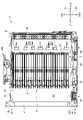
- FIG. 1 is an exploded perspective view showing a state in which a plurality of substrates W are stored in a substrate storage container 1 according to an embodiment of the present invention
- FIG. 1 is an upper perspective view showing a container body 2 of a substrate storage container 1 according to an embodiment of the present invention
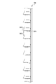
- FIG. 2 is a bottom perspective view showing the container body 2 of the substrate storage container 1 according to the embodiment of the present invention
- FIG. 4 is a side cross-sectional view showing the container body 2 cut along line AA in FIG. 3.
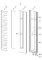
- FIG. 3 is a perspective view showing a projecting portion 8 of the substrate storage container 1
- FIG. 3 is an exploded perspective view showing a projecting portion 8 of the substrate storage container 1;
- FIG. 4 is an exploded perspective view showing the flow of purge gas inside a protrusion main body 81 that constitutes the protrusion 8 of the substrate storage container 1.
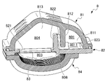
- FIG. 3 is a rear perspective cross-sectional view showing a projecting portion 8 of the substrate storage container 1.
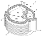
- FIG. 3 is a front perspective cross-sectional view showing a projecting portion 8 of the substrate storage container 1.
- FIG. 3 is a side view showing a nozzle section chamber forming section 84 that constitutes the protruding section 8 of the substrate storage container 1.
- FIG. 1 is an exploded perspective view showing a state in which a plurality of substrates W are stored in a substrate storage container 1.
- FIG. 2 is an upper perspective view showing the container body 2 of the substrate storage container 1.
- FIG. 3 is a bottom perspective view showing the container body 2 of the substrate storage container 1.
- FIG. 4 is a side cross-sectional view showing the container body 2 cut along line AA in FIG.
- the direction from the container body 2 to the lid body 3 described later is defined as the forward direction D11, and the opposite direction is defined as the rearward direction D12, These are collectively defined as the front-rear direction D1.
- the direction from the lower wall 24 to the upper wall 23 is defined as an upward direction D21, and the opposite direction is defined as a downward direction D22.
- the direction from the second side wall 26 to the first side wall 25 described later is defined as the left direction D31, and the opposite direction is defined as the right direction D32. are collectively defined as a left-right direction D3. Arrows indicating these directions are illustrated in the main drawings.
- the substrates W (see FIG. 1) stored in the substrate storage container 1 are disk-shaped silicon wafers, glass wafers, sapphire wafers, etc., and are thin for industrial use.
- the substrate W in this embodiment is a silicon wafer with a diameter of 300 mm.
- the substrate storage container 1 stores substrates W made of silicon wafers as described above, and is used as a process container for transporting in a process in a factory. It is used as a shipping container for transporting substrates by transportation means such as shipping means, shipping means, etc., and is composed of a container body 2 and a lid 3 .
- the container body 2 includes a substrate support plate-like portion 5 as a side substrate support portion and a back side substrate support portion 6 .
- the lid 3 has a front retainer (not shown) as a lid-side substrate supporting portion.
- the container body 2 has a cylindrical wall 20 with a container body opening 21 formed at one end and a closed other end.
- a substrate storage space 27 is formed in the container body 2 .
- the substrate storage space 27 is formed by being surrounded by the wall portion 20 .
- a substrate support plate-like portion 5 is arranged in a portion of the wall portion 20 that forms the substrate storage space 27 .
- a plurality of substrates W can be stored in the substrate storage space 27 as shown in FIG.
- the board support plate-shaped part 5 is an interior component arranged in a pair in the board storage space 27 and is detachably fixed to the wall part 20 .
- the substrate support plate-shaped part 5 can support the edge portions of the plurality of substrates W by contacting the edge portions of the plurality of substrates W while the adjacent substrates W are spaced apart from each other by a predetermined distance and arranged in parallel. is.
- a rear substrate support portion 6 is formed integrally with the substrate support plate-shaped portion 5 and provided.
- the back side substrate support portion 6 is provided on the wall portion 20 so as to form a pair with a front retainer (not shown) described later in the substrate storage space 27 .
- the far side substrate supporting portion 6 can support the rear portion of the edge portions of the plurality of substrates W by coming into contact with the edge portions of the plurality of substrates W. As shown in FIG.
- the lid 3 is attachable to and detachable from the opening rim 28 forming the container body opening 21 and can close the container body opening 21 .
- a front retainer (not shown) is provided at a portion of the lid 3 that faces the substrate storage space 27 when the container main body opening 21 is closed by the lid 3 .
- the front retainer is arranged inside the board storage space 27 so as to form a pair with the back side board support portion 6 .
- the front retainer can support the front portions of the edges of the plurality of substrates W by coming into contact with the edges of the plurality of substrates W when the container body opening 21 is closed by the lid 3 .
- the front retainer supports a plurality of substrates W in cooperation with the inner substrate support portion 6 when the container main body opening 21 is closed by the lid 3, thereby keeping the adjacent substrates W at a predetermined distance. They are held in a state of being spaced apart and arranged side by side.
- the substrate storage container 1 is made of a resin such as a plastic material.
- the resin material include polycarbonate, cycloolefin polymer, polyetherimide, polyetherketone, and polybutylene.
- Thermoplastic resins such as terephthalate, polyetheretherketone, and liquid crystal polymers, and alloys thereof can be mentioned.
- conductive substances such as carbon fibers, carbon powders, carbon nanotubes, and conductive polymers are selectively added. Further, it is also possible to add glass fiber, carbon fiber, or the like in order to increase rigidity.
- the wall portion 20 of the container body 2 has a back wall 22, an upper wall 23, a lower wall 24, a first side wall 25 and a second side wall .
- the inner wall 22, the upper wall 23, the lower wall 24, the first side wall 25, and the second side wall 26 are made of the material described above and are integrally formed.
- the first side wall 25 and the second side wall 26 face each other, and the upper wall 23 and the lower wall 24 face each other.
- a rear end of the upper wall 23 , a rear end of the lower wall 24 , a rear end of the first side wall 25 , and a rear end of the second side wall 26 are all connected to the inner wall 22 .
- the front end of the upper wall 23, the front end of the lower wall 24, the front end of the first side wall 25, and the front end of the second side wall 26 form an opening peripheral edge 28 that forms the container body opening 21 having a substantially rectangular shape.
- the opening peripheral edge 28 is provided at one end of the container body 2 , and the inner wall 22 is located at the other end of the container body 2 .
- the outer shape of the container body 2 formed by the outer surface of the wall portion 20 is box-shaped.
- the inner surface of the wall portion 20, that is, the inner surface of the back wall 22, the inner surface of the upper wall 23, the inner surface of the lower wall 24, the inner surface of the first side wall 25, and the inner surface of the second side wall 26, is a substrate storage space surrounded by these. 27 is formed.
- a container main body opening 21 formed in an opening peripheral portion 28 communicates with a substrate storage space 27 that is surrounded by a wall portion 20 and formed inside the container main body 2 .
- a maximum of 25 substrates W can be stored in the substrate storage space 27 .
- Latch engaging recesses 231A, 231B, 241A, and 241B recessed toward the outside of the substrate storage space 27 are formed in the portions of the upper wall 23 and the lower wall 24 in the vicinity of the opening peripheral portion 28. ing. A total of four latch engagement recesses 231A, 231B, 241A, and 241B are formed near the left and right ends of the upper wall 23 and the lower wall 24, respectively.
- a rib 235 is formed integrally with the upper wall 23 on the outer surface of the upper wall 23 . Ribs 235 increase the rigidity of container body 2 .
- a top flange 236 is fixed to the central portion of the upper wall 23 . The top flange 236 is a member that is hung and suspended in the substrate storage container 1 when suspending the substrate storage container 1 in an AMHS (automatic wafer transfer system), a PGV (wafer substrate carrier), or the like.
- a bottom plate 244 is fixed to the lower wall 24 .
- the bottom plate 244 has a substantially rectangular plate shape arranged to face substantially the entire bottom surface that constitutes the outer surface of the bottom wall 24 , and is fixed to the bottom wall 24 .
- an air supply hole 242 In the vicinity of the four corners of the lower wall 24, two types of through holes, namely, an air supply hole 242 and an exhaust hole 243 are formed.
- the two through-holes in the front part of the lower wall 24 are exhaust holes 243 for discharging the gas inside the container body 2
- the two through-holes in the rear part are the container body 2 .
- An air supply filter portion 98 as an additional component is arranged in the through hole as the air supply hole 242 , and an exhaust filter portion 99 is arranged in the through hole as the exhaust hole 243 . That is, the flow path of the gas inside the air supply filter portion 98 and the exhaust filter portion 99 constitutes a part of the air passage that allows communication between the substrate storage space 27 and the space outside the container body 2 .
- the air supply filter portion 98 and the exhaust filter portion 99 are arranged on the wall portion 20 , and the air supply filter portion 98 and the exhaust filter portion 99 are separated from the space outside the container body 2 .
- Gas can pass through a filter (not shown) between the substrate storage space 27 and the substrate storage space 27 .
- the purge gas supplied to the air supply filter unit 98 is configured to be supplied to the substrate storage space 27 .
- the exhaust filter section 99 is configured to allow gas to pass from the substrate storage space 27 to the space outside the container body 2 .
- the back wall 22 has a projecting portion 8 (see FIG. 5) as a gas ejection nozzle portion.
- the protrusion 8 has a protrusion main body 81, an inner wall 82, a hydrophobic film 83, and a nozzle chamber forming portion 84, which are arranged in this order: As shown in FIG. 6, they are fixed together to form a protrusion 8 .
- Two protrusions 8 are provided in pairs.
- the base portion 819 of the protruding portion main body portion 81 having an annular groove 8191 formed therein and fitted with an O-ring (not shown) as a sealing member in the groove 8191 is arranged so as to airtightly communicate with the air passage inside the air supply filter portion 98 .
- the hole formed in the lower wall 24 of the container body 2 is also provided with a sealing member (not shown) that seals against the base 819 .
- the upper portion of the projecting portion 8, which is the portion on the tip side of the projecting portion 8, is fixed to the back wall 22 forming the wall portion 20 by snap fitting, welding, or the like.
- the pair of protrusions 8 protrude like ribs toward the opening 21 of the container body and extend in parallel from the upper end to the lower end of the inner wall 22 .
- the projecting portion 8 has a hollow columnar shape.
- the protruding portion 8 allows the substrate storage space 27 and the space outside the container body 2 to pass through the substrate storage space 27 .
- the gas flow equalization unit includes an air passage (a gas flow passage inside the air supply filter unit 98) that allows communication between the substrate storage space 27 and the space outside the container body 2, and an opening. It is located between 841 and The gas flow rate equalizing unit blocks linear communication between the gas retention chamber 801, the pre-gas outflow holding chamber 804, and the gas retention chamber 801 and the pre-gas outflow holding chamber 804, thereby separating the gas retention chamber 801 and the gas flow equalization unit. It has a chamber partition (body-side partition 812 , inner-wall-side partition 822 ) that forms an inter-chamber flow path 806 that communicates with the pre-outflow holding chamber 804 , and a nozzle section chamber 803 .
- an air passage a gas flow passage inside the air supply filter unit 98
- the gas retention chamber 801 is a space surrounded by the protrusion main body 81, the inner wall 82, and the partitions between the chambers (main body side partition 812, inner wall side partition 822). It is composed of
- the pre-gas outflow holding chamber 804 includes a protruding portion main body portion 81, an inner wall portion 82, a hydrophobic film 83 provided to block a through hole formed in the inner wall portion 82, and a partition (main body side partition). 812, inner wall side partition 822), and the space surrounded by.
- the nozzle chamber 803 is composed of a space surrounded by the nozzle chamber forming portion 84 and the inner wall portion 82 , a hydrophobic film 83 provided to close the through hole formed in the inner wall portion 82 .
- the gas retention chamber 801 is partitioned into a plurality of gas retention compartments by compartment partitions 811 provided at predetermined intervals in the vertical direction.
- the compartment partition 811 does not completely partition the gas retention chamber 801 to prevent the purge gas from flowing between the plurality of gas retention compartments, but forms a gas circulation space 8011 with the inner wall portion 82 . there is Therefore, the purge gas can flow between the vertically adjacent gas retention compartments.
- the gas circulation space 8011 does not linearly communicate with the gas retention chamber 801 from the bottom to the top of the projecting portion 8 in the vertical direction.
- the internal wall portion 82 is provided with a sub-chamber partition 823 extending from the internal wall portion 82 toward the inside of the gas retention chamber 801 . Therefore, the purge gas that has flowed into the gas retention chamber 801 from the air passage of the air supply filter unit 98 flows through all of the gas retention compartments that are formed into crank-shaped gas supply channels 8011 by the partitions 811 and 823 between compartments. , and flows from the lowest end to the uppermost end of the gas retention chamber 801.
- the pre-gas outflow holding chamber 804 is partitioned into a plurality of pre-gas outflow holding compartments by partition walls 813 provided at predetermined intervals in the vertical direction.
- the partition wall 813 completely partitions the pre-gas outflow holding chamber 804 so that the purge gas cannot flow between the plurality of pre-gas outflow holding compartments. Therefore, the purge gas that has flowed into each of the pre-gas outflow holding compartments flows into the nozzle section chamber 803 through the hydrophobic membrane 83 .
- the plurality of pre-gas outflow retention compartments partitioned by partition walls 813 have a uniform volume.
- the hydrophobic film 83 is fixed in a state of being fitted into a recess formed on the front side of the inner wall portion 82 around the through holes 821 formed in the inner wall portion 82 .
- the hydrophobic film 83 is composed of a hydrophobic film whose flow resistance does not change even if it gets wet when the container body 2 of the substrate storage container 1 is washed.
- a porous membrane or sheet having air permeability and hydrophobic performance, or a coated product having hydrophobic performance is used.
- a PTFE membrane is used as a hydrophobic membrane 83.
- No partitions between sub-chambers or partition walls are provided inside the nozzle section chamber 803 . Therefore, it is formed as one chamber that continues continuously from the lower end to the upper end.
- a plurality of openings 841 are formed on the front side of the nozzle section chamber forming section 84 in which the nozzle section chamber 803 is formed.
- the number of openings 841 corresponding to each of the substrates W that can be accommodated in the substrate accommodation space 27, specifically, 25 openings 841 is formed.
- the nozzle section chamber 803 communicates with all the openings 841 , and also communicates with all the gas pre-outflow holding compartments partitioned by the partition wall 813 through the hydrophobic membrane 83 .
- inclined eaves 842 that are inclined in the downward direction D22 as they advance in the forward direction D11 are provided so as to protrude in the forward direction D11 from the lower side of the opening 841.
- the inclined eaves 842 extend parallel to each other.
- the inclined canopy 842 prevents the cleaning liquid from flowing into the nozzle chamber 803 from the opening 841 when cleaning the container body 2 .
- the slanted eaves 842 form a predetermined direction outflow portion that causes the gas to flow out from the opening 841 in the downward direction D22.
- the lid 3 has a substantially rectangular shape that substantially matches the shape of the opening peripheral portion 28 of the container body 2 .
- the lid 3 is attachable to and detachable from the opening rim 28 of the container body 2 .
- the lid 3 is surrounded by the opening rim 28 .
- the opening 21 of the container body can be closed.
- An annular seal member 4 is attached to the surface facing the surface of the formed stepped portion (seal surface 281 ) so as to encircle the outer peripheral edge of the lid 3 .
- the sealing member 4 is arranged so as to encircle the lid 3 .
- the sealing member 4 is made of various thermoplastic elastomers such as elastically deformable polyester-based and polyolefin-based elastomers, fluororubber, silicon rubber, and the like.
- the sealing member 4 When the lid 3 is attached to the opening peripheral portion 28 , the sealing member 4 is sandwiched between the sealing surface 281 of the container body 2 and the inner surface of the lid 3 and is elastically deformed. That is, the sealing member 4 is interposed between the lid 3 and the container body 2, so that the lid 3 and the container body 2 are separated from each other without contacting each other.
- the opening 21 can be closed.
- the substrate W By removing the lid 3 from the opening peripheral portion 28 , the substrate W can be taken in and out of the substrate storage space 27 inside the container body 2 .
- a latch mechanism is provided in the lid body 3 .
- the latch mechanism is provided in the vicinity of both left and right ends of the lid 3, and as shown in FIG. 3 are provided with two lower latch portions 32B, 32B that can protrude in the downward direction D22.
- the two upper latch portions 32A, 32A are arranged near the left and right ends of the upper side of the lid 3, and the two lower latch portions 32B, 32B are arranged near the left and right ends of the lower side of the lid 3. .
- An operation part 33 is provided on the outer surface of the lid body 3 .
- the upper latch portions 32A, 32A and the lower latch portions 32B, 32B can be projected from the upper side and the lower side of the lid 3, or can be projected from the upper side and the lower side. It can be in a non-protruding state.
- the upper latch portions 32A, 32A protrude in the upward direction D21 from the upper side of the lid 3 and engage with the latch engaging recesses 231A, 231B of the container body 2, and the lower latch portions 32B, 32B of the lid 3
- the lid 3 is fixed to the container body opening 21 of the container body 2 by protruding downward D22 from the lower side and engaging with the latch engaging recesses 241A and 241B of the container body 2 .
- a concave portion (not shown) recessed outward (frontward D11) of the substrate storage space 27 is formed inside the lid 3 (the rearward D12 side of the lid 3 in FIG. 1).
- a front retainer (not shown) is fixedly provided in the recess.
- the front retainer (not shown) has a front retainer board receiving portion (not shown).
- the front retainer board receiving portions (not shown) are arranged two by two so as to form a pair at a predetermined interval in the left-right direction. Twenty-five pairs of the front retainer board receiving portions, which are arranged in pairs in this manner, are arranged in parallel in the vertical direction.
- the front retainer substrate receiving portion supports the edge of the substrate W. As shown in FIG.
- the substrate storage container 1 according to this embodiment has an opening peripheral portion 28 with a container main body opening 21 formed at one end and a cylindrical wall portion 20 closed at the other end.
- gas retention chamber 801, pre-gas outflow holding chamber 804 a gas flow equalizing unit
- gas flow equalization unit includes the gas retention chamber 801, the pre-gas outflow holding chamber 804, and the gas retention chamber 801. Partitions between chambers (body-side partitions 812, Inner wall side partition 822).
- the purge gas retained in the gas retention chamber 801 flows through the inter-chamber flow path 806 into each of the plurality of pre-gas outflow retention compartments of the pre-gas outflow retention chamber 804, flows into the nozzle section chamber 803, and is retained therein. , so that the liquid can uniformly flow out from each of the plurality of openings 841 of the nozzle section chamber forming section 84 .
- the purge gas can be uniformly supplied from the plurality of openings 841 to the substrates W stored in the substrate storage space 27 .
- the gas flow rate equalizing section has the partition wall 813 that partitions the pre-gas outflow holding chamber 804 into a plurality of pre-gas outflow holding compartments.
- the purge gas that has flowed into the pre-gas-outflow holding chamber 804 can be divided into a plurality of pre-gas-outflow holding subchambers and temporarily retained therein.
- the purge gas is temporarily retained, so that the purge gas is temporarily retained and uniform in each pre-gas outflow retention compartment.
- the vaporized purge gas flows into nozzle section chamber 803 . Therefore, it is possible to prevent the purge gas that has flowed into the nozzle section chamber 803 from strongly flowing out from the predetermined opening 841 .
- the plurality of pre-gas outflow holding compartments have a uniform volume. With this configuration, it is possible to minimize the difference in the amount of purge gas flowing into the nozzle section chamber 803 through the hydrophobic membrane 83 from the pre-gas outflow holding compartment.
- the gas retention chamber 801 is partitioned into a plurality of gas retention compartments by the compartment partitions 811 .
- the purge gas that has flowed into the lower end portion of the gas retention chamber 801 can be prevented from vigorously reaching the upper end portion of the gas retention chamber 801 . Therefore, it is possible to prevent a large amount of purge gas from flowing into the upper end portion of the gas retention chamber 801 .
- the gas circulation space 8011 is formed as a gas supply channel that communicates with all the gas retention compartments.
- the purge gas that has flowed into the gas retention chamber 801 can be communicated with all the gas retention compartments, and can flow from each gas retention compartment to each pre-gas outflow retention compartment that constitutes the pre-gas outflow retention chamber 804 . becomes.
- the projecting portion 8 as the gas ejection nozzle portion has the nozzle portion chamber 803 communicating with the opening portion 841 , and the nozzle portion chamber 803 communicates through the hydrophobic film 83 . , and communicates with the holding chamber 804 before gas outflow.
- the hydrophobic film 83 does not change the flow resistance, and can prevent the cleaning liquid from flowing into the holding chamber 804 before gas outflow. It becomes possible.
- the nozzle section chamber 803 communicates with all the openings 841 and all the pre-gas outflow holding compartments constituting the pre-gas outflow holding chamber 804 .
- This configuration allows the purge gas that has flowed into all the pre-gas outflow holding compartments constituting the pre-gas outflow holding chamber 804 to flow into the nozzle section chamber 803 that communicates with all the openings 841 .
- the protruding portion 8 as the gas ejection nozzle portion has the inclined eaves 842 as the predetermined direction outflow portion for causing the gas to flow out from the opening portion 841 in a predetermined direction.
- the protruding portion 8 as the gas ejection nozzle portion has the inclined eaves 842 as the predetermined direction outflow portion for causing the gas to flow out from the opening portion 841 in a predetermined direction.
- the openings 841 are formed corresponding to each of the plurality of substrates W stored in the substrate storage space 27 .
- the purge gas flowing out from one opening 841 is assigned to one substrate W, it is possible to reliably flow the purge gas to each substrate W one by one.
- the columnar projecting portion 8 having the gas ejection nozzle portion and the gas flow uniforming portion is provided, and the base portion 819 of the projecting portion 8 is the wall portion of the container body 2. It is inserted into a hole formed in the container body 20 forming an air passage and provided with a sealing member, and the tip side portion of the projecting portion 8 is fixed to the wall portion 20 of the container body 2 . Thus, the projecting portion 8 is fixed to the container body 2 . With this configuration, it is possible to easily and reliably fix the projecting portion 8 to the container body 2 .
- the configuration of the projection main body, the inner wall, the hydrophobic film, the nozzle chamber forming portion, etc., which constitute the projection is the projection main body 81 and the inner wall 82 which constitute the projection 8. , the hydrophobic film 83, the nozzle section chamber forming section 84, and the like.
- the shape of the container main body and the lid, the number and dimensions of the substrates that can be accommodated in the container main body are the shapes of the container main body 2 and the lid 3 in this embodiment, and the number and dimensions of the substrates W that can be accommodated in the container main body 2. is not limited to
Abstract
A substrate container 1 includes: a container body 2; a lid 3; a gas passage 98, 99 that enables a substrate housing space 27 to communicate with a space outside of the container body 2; a gas ejection nozzle part 8 having multiple openings 841 for supplying a gas flowed into the gas passage 98, 99 to the substrate housing space 27; and a gas flow equalization part 801, 803, 804 that enables the gas to flow out from the multiple openings 841 at an equalized flow rate. The gas flow equalization part includes a gas retention chamber 801, a pre-outflow gas retention chamber 804, and an inter-chamber partition 812, 822 that prevents the gas retention chamber 801 and the pre-outflow gas retention chamber 804 from linearly communicating with each other and forms an inter-chamber flow path 806 through which the gas retention chamber 801 and the pre-outflow gas retention chamber 804 communicate with each other.
Description
本発明は、半導体ウェーハ、レチクル、プリント基板などの基板を収納、保管、搬送、輸送等する際に使用される基板収納容器に関する。
The present invention relates to a substrate storage container used for storing, storing, transporting, transporting substrates such as semiconductor wafers, reticles, and printed substrates.
各種基板を収納する基板収納容器としては、容器本体と蓋体とを備える構成のものが、従来より知られている。
As a substrate storage container for storing various substrates, one having a configuration including a container body and a lid has been conventionally known.
容器本体の一端部は、容器本体開口部を有する。容器本体の他端部は、閉塞された筒状の壁部を有する。容器本体内には基板収納空間が形成されている。基板収納空間は、壁部により取り囲まれて形成されており、基板を収納可能である。蓋体は、容器本体開口部に対して着脱可能であり、容器本体開口部を閉塞可能である。側方基板支持部は、基板収納空間内において対をなすように壁部に設けられている。側方基板支持部は、蓋体によって容器本体開口部が閉塞されていないときに、隣接する基板同士を所定の間隔で離間させて並列させた状態で、基板の縁部を支持可能である。
One end of the container body has a container body opening. The other end of the container body has a closed cylindrical wall. A substrate storage space is formed in the container body. The substrate storage space is formed by being surrounded by walls, and is capable of storing the substrate. The lid is attachable to and detachable from the opening of the container body, and can close the opening of the container body. The lateral substrate support portions are provided on the wall portion so as to form a pair within the substrate storage space. When the opening of the container main body is not closed by the lid, the side substrate supporting portion can support the edges of the substrates while the adjacent substrates are spaced apart from each other by a predetermined distance and arranged side by side.
蓋体の部分であって容器本体開口部を閉塞しているときに基板収納空間に対向する部分には、フロントリテーナ(蓋体側基板支持部)が設けられている。フロントリテーナは、蓋体によって容器本体開口部が閉塞されているときに、基板の縁部を支持可能である。また、フロントリテーナと対をなすようにして、奥側基板支持部が壁部に設けられている。奥側基板支持部は、基板の縁部を支持可能である。奥側基板支持部は、蓋体によって容器本体開口部が閉塞されているときに、フロントリテーナと協働して基板を支持することにより、隣接する基板同士を所定の間隔で離間させて並列させた状態で、基板を支持する。
A front retainer (lid-side substrate support portion) is provided in a portion of the lid that faces the substrate storage space when the opening of the container body is closed. The front retainer can support the edge of the substrate when the opening of the container body is closed by the lid. Further, a back side substrate supporting portion is provided on the wall portion so as to form a pair with the front retainer. The far side substrate supporting portion can support the edge of the substrate. When the opening of the container main body is closed by the lid, the back side substrate supporting portion supports the substrates in cooperation with the front retainer, so that the adjacent substrates are spaced apart from each other by a predetermined distance and arranged side by side. support the substrate.
基板収納空間と、基板収納容器の外部とを連通する通気孔である掃気孔を有する基板収納容器においては、蓋体を取り外した状態でクリーンドライエア(CDA)や、窒素(N2)がパージガスとして用いられ、基板収納容器の外部のロードポートから供給される当該パージガスは、容器本体の下面(外面)より貫通孔を通じて、基板収納容器内面に設置された気体噴出ノズル部へ供給される。これによりガスパージが行われる。この際、ガスパージによるパージガスの置換を確実に行うために、気体噴出ノズル部の複数の開口部から、パージガスが均一に供給されることが要求される。
Clean dry air (CDA) or nitrogen (N 2 ) is used as a purge gas in a substrate storage container having a scavenging hole, which is a ventilation hole communicating between the substrate storage space and the outside of the substrate storage container, with the lid removed. The purge gas used and supplied from the load port outside the substrate storage container is supplied from the lower surface (outer surface) of the container body through the through-holes to the gas ejection nozzle section installed on the inner surface of the substrate storage container. Gas purging is thereby performed. At this time, in order to reliably replace the purge gas by gas purging, it is required that the purge gas be uniformly supplied from a plurality of openings of the gas ejection nozzle section.
本発明は、基板収納空間において気体を気体噴出ノズル部の複数の開口部から均一に供給可能な基板収納容器を提供することを目的とする。
An object of the present invention is to provide a substrate storage container capable of uniformly supplying gas from a plurality of openings of a gas ejection nozzle section in a substrate storage space.
本発明は、一端部に容器本体開口部が形成された開口周縁部を有し、他端部が閉塞された筒状の壁部を備え、前記壁部の内面によって、基板を収納可能であり前記容器本体開口部に連通する基板収納空間が形成された容器本体と、前記容器本体開口部に対して着脱可能であり、前記容器本体開口部を閉塞可能な蓋体と、前記基板収納空間と前記容器本体の外部の空間とを連通可能な通気路と、前記通気路に流入した気体を前記基板収納空間に供給する複数の開口部を有する気体噴出ノズル部と、前記複数の開口部から均一化された流量で気体を流出可能とする気体流量均一化部と、を備え、前記気体流量均一化部は、気体滞留室と、気体流出前保持室と、前記気体滞留室と前記気体流出前保持室とを直線的に連通することを遮蔽して前記気体滞留室と前記気体流出前保持室とを連通する室間流路を形成する室間間仕切りと、を有する基板収納容器に関する。
The present invention includes a cylindrical wall portion having an opening peripheral portion formed with a container main body opening at one end portion and a cylindrical wall portion closed at the other end portion, and a substrate can be accommodated by the inner surface of the wall portion. a container body in which a substrate storage space communicating with the container body opening is formed; a lid that is attachable to and detachable from the container body opening and capable of closing the container body opening; and the substrate storage space. an air passage capable of communicating with the space outside the container body; a gas ejection nozzle portion having a plurality of openings for supplying the gas flowing into the air passage to the substrate storage space; a gas flow equalizing unit that allows the gas to flow out at a uniform flow rate, wherein the gas flow equalizing unit includes a gas retention chamber, a pre-gas outflow holding chamber, and a gas retention chamber and a pre-gas outflow The present invention relates to a substrate storage container having an inter-chamber partition that forms an inter-chamber flow path that blocks linear communication between the holding chamber and the gas retention chamber and the pre-gas outflow holding chamber.
また、前記気体流量均一化部は、前記気体流出前保持室を複数の気体流出前保持分室に区画する区画壁を有することが好ましい。また、前記複数の気体流出前保持分室は均一の容積を有することが好ましい。また、前記気体滞留室は、分室間間仕切りにより複数の気体滞留分室に仕切られていることが好ましい。また、全ての前記気体滞留分室に連通する気体供給流路が形成されていることが好ましい。
Further, it is preferable that the gas flow equalizing section has a partition wall that partitions the pre-gas outflow holding chamber into a plurality of pre-gas outflow holding compartments. Further, it is preferable that the plurality of pre-gas outflow retention compartments have a uniform volume. Further, it is preferable that the gas retention chamber is partitioned into a plurality of gas retention compartments by partitions between compartments. Further, it is preferable that a gas supply channel communicating with all of the gas retention compartments is formed.
また、前記気体噴出ノズル部は、開口部に連通するノズル部室を有し、前記ノズル部室は、疎水性膜を介して前記気体流出前保持室に連通することが好ましい。また、前記ノズル部室は、全ての開口部及び全ての前記気体流出前保持分室に連通することが好ましい。また、前記気体噴出ノズル部は、前記開口部から気体を所定の方向へ向けて流出させる所定方向流出部を有することが好ましい。
Further, it is preferable that the gas ejection nozzle section has a nozzle section chamber that communicates with the opening, and the nozzle section chamber communicates with the pre-gas outflow holding chamber via a hydrophobic membrane. Further, the nozzle section chamber preferably communicates with all the openings and all the pre-gas outflow holding compartments. Moreover, it is preferable that the gas ejection nozzle section has a predetermined direction outflow section for causing the gas to flow out in a predetermined direction from the opening.
また、前記開口部は、前記基板収納空間に収納される複数の前記基板のそれぞれに対応して形成されていることが好ましい。また、前記気体噴出ノズル部と前記気体流量均一化部とを有する柱状の突出部を備え、前記突出部の基部は、前記容器本体の前記壁部に形成され前記通気路を形成する穴であってシール部材が設けられた穴に挿入される共に、前記突出部の先端側の部分は、前記容器本体の前記壁部に対して固定されることにより、前記突出部は前記容器本体に固定されることが好ましい。
Further, it is preferable that the opening is formed corresponding to each of the plurality of substrates accommodated in the substrate accommodation space. Further, a columnar protrusion having the gas ejection nozzle and the gas flow equalizing portion is provided, and the base of the protrusion is a hole formed in the wall of the container body and forming the air passage. The protruding portion is fixed to the container body by inserting the protruding portion into the hole provided with the sealing member and fixing the tip side portion of the protruding portion to the wall portion of the container body. preferably.
本発明によれば、基板収納空間において気体を気体噴出ノズル部の複数の開口部から均一に供給可能な基板収納容器を提供することができる。
According to the present invention, it is possible to provide a substrate storage container capable of uniformly supplying gas from a plurality of openings of the gas ejection nozzle section in the substrate storage space.
〔基板収納容器1の全体構成〕
以下、本実施形態による基板収納容器1について、図面を参照しながら説明する。
図1は、基板収納容器1に複数の基板Wが収納された様子を示す分解斜視図である。図2は、基板収納容器1の容器本体2を示す上方斜視図である。図3は、基板収納容器1の容器本体2を示す下方斜視図である。図4は、図3のA-A線で切断した容器本体2を示す側方断面図である。 [Overall Configuration of Substrate Storage Container 1]
Hereinafter, the substrate storage container 1 according to this embodiment will be described with reference to the drawings.
FIG. 1 is an exploded perspective view showing a state in which a plurality of substrates W are stored in a substrate storage container 1. FIG. FIG. 2 is an upper perspective view showing thecontainer body 2 of the substrate storage container 1. FIG. FIG. 3 is a bottom perspective view showing the container body 2 of the substrate storage container 1. FIG. FIG. 4 is a side cross-sectional view showing the container body 2 cut along line AA in FIG.
以下、本実施形態による基板収納容器1について、図面を参照しながら説明する。
図1は、基板収納容器1に複数の基板Wが収納された様子を示す分解斜視図である。図2は、基板収納容器1の容器本体2を示す上方斜視図である。図3は、基板収納容器1の容器本体2を示す下方斜視図である。図4は、図3のA-A線で切断した容器本体2を示す側方断面図である。 [Overall Configuration of Substrate Storage Container 1]
Hereinafter, the substrate storage container 1 according to this embodiment will be described with reference to the drawings.
FIG. 1 is an exploded perspective view showing a state in which a plurality of substrates W are stored in a substrate storage container 1. FIG. FIG. 2 is an upper perspective view showing the
ここで、説明の便宜上、後述の容器本体2から蓋体3へ向かう方向(図1における右上から左下へ向かう方向)を前方向D11と定義し、その反対の方向を後方向D12と定義し、これらをあわせて前後方向D1と定義する。また、後述の下壁24から上壁23へと向かう方向(図1における上方向)を上方向D21と定義し、その反対の方向を下方向D22と定義し、これらをあわせて上下方向D2と定義する。また、後述する第2側壁26から第1側壁25へと向かう方向(図1における右下から左上へ向かう方向)を左方向D31と定義し、その反対の方向を右方向D32と定義し、これらをあわせて左右方向D3と定義する。主要な図面には、これらの方向を示す矢印を図示している。
Here, for convenience of explanation, the direction from the container body 2 to the lid body 3 described later (the direction from the upper right to the lower left in FIG. 1) is defined as the forward direction D11, and the opposite direction is defined as the rearward direction D12, These are collectively defined as the front-rear direction D1. The direction from the lower wall 24 to the upper wall 23 (upward direction in FIG. 1) is defined as an upward direction D21, and the opposite direction is defined as a downward direction D22. Define. Further, the direction from the second side wall 26 to the first side wall 25 described later (the direction from the lower right to the upper left in FIG. 1) is defined as the left direction D31, and the opposite direction is defined as the right direction D32. are collectively defined as a left-right direction D3. Arrows indicating these directions are illustrated in the main drawings.
また、基板収納容器1に収納される基板W(図1参照)は、円盤状のシリコンウェーハ、ガラスウェーハ、サファイアウェーハ等であり、産業に用いられる薄いものである。本実施形態における基板Wは、直径300mmのシリコンウェーハである。
Also, the substrates W (see FIG. 1) stored in the substrate storage container 1 are disk-shaped silicon wafers, glass wafers, sapphire wafers, etc., and are thin for industrial use. The substrate W in this embodiment is a silicon wafer with a diameter of 300 mm.
図1~図4に示すように、基板収納容器1は、上述のようなシリコンウェーハからなる基板Wを収納して、工場内の工程において搬送する工程内容器として用いられたり、陸運手段・空運手段・海運手段等の輸送手段により基板を輸送するための出荷容器として用いられたりするものであり、容器本体2と、蓋体3とから構成される。容器本体2は、側方基板支持部としての基板支持板状部5と、奥側基板支持部6とを備えている。蓋体3は、蓋体側基板支持部としての図示しないフロントリテーナを備えている。
As shown in FIGS. 1 to 4, the substrate storage container 1 stores substrates W made of silicon wafers as described above, and is used as a process container for transporting in a process in a factory. It is used as a shipping container for transporting substrates by transportation means such as shipping means, shipping means, etc., and is composed of a container body 2 and a lid 3 . The container body 2 includes a substrate support plate-like portion 5 as a side substrate support portion and a back side substrate support portion 6 . The lid 3 has a front retainer (not shown) as a lid-side substrate supporting portion.
容器本体2は、一端部に容器本体開口部21が形成され、他端部が閉塞された筒状の壁部20を有する。容器本体2内には基板収納空間27が形成されている。基板収納空間27は、壁部20により取り囲まれて形成されている。壁部20の部分であって基板収納空間27を形成している部分には、基板支持板状部5が配置されている。基板収納空間27には、図1に示すように、複数の基板Wを収納可能である。
The container body 2 has a cylindrical wall 20 with a container body opening 21 formed at one end and a closed other end. A substrate storage space 27 is formed in the container body 2 . The substrate storage space 27 is formed by being surrounded by the wall portion 20 . A substrate support plate-like portion 5 is arranged in a portion of the wall portion 20 that forms the substrate storage space 27 . A plurality of substrates W can be stored in the substrate storage space 27 as shown in FIG.
基板支持板状部5は、基板収納空間27内において対をなすように配置された内装部品であり、壁部20に着脱可能に固定されて設けられている。基板支持板状部5は、複数の基板Wの縁部に当接することにより、隣接する基板W同士を所定の間隔で離間させて並列させた状態で、複数の基板Wの縁部を支持可能である。基板支持板状部5の奥側には、奥側基板支持部6が基板支持板状部5と一体成形されて設けられている。
The board support plate-shaped part 5 is an interior component arranged in a pair in the board storage space 27 and is detachably fixed to the wall part 20 . The substrate support plate-shaped part 5 can support the edge portions of the plurality of substrates W by contacting the edge portions of the plurality of substrates W while the adjacent substrates W are spaced apart from each other by a predetermined distance and arranged in parallel. is. On the far side of the substrate support plate-shaped portion 5, a rear substrate support portion 6 is formed integrally with the substrate support plate-shaped portion 5 and provided.
奥側基板支持部6は、基板収納空間27内において後述する図示しないフロントリテーナと対をなすように壁部20に設けられている。奥側基板支持部6は、複数の基板Wの縁部に当接することにより、複数の基板Wの縁部の後部を支持可能である。
The back side substrate support portion 6 is provided on the wall portion 20 so as to form a pair with a front retainer (not shown) described later in the substrate storage space 27 . The far side substrate supporting portion 6 can support the rear portion of the edge portions of the plurality of substrates W by coming into contact with the edge portions of the plurality of substrates W. As shown in FIG.
蓋体3は、容器本体開口部21を形成する開口周縁部28に対して着脱可能であり、容器本体開口部21を閉塞可能である。図示しないフロントリテーナは、蓋体3の部分であって蓋体3によって容器本体開口部21が閉塞されているときに基板収納空間27に対向する部分に設けられている。フロントリテーナは、基板収納空間27の内部において奥側基板支持部6と対をなすように配置されている。
The lid 3 is attachable to and detachable from the opening rim 28 forming the container body opening 21 and can close the container body opening 21 . A front retainer (not shown) is provided at a portion of the lid 3 that faces the substrate storage space 27 when the container main body opening 21 is closed by the lid 3 . The front retainer is arranged inside the board storage space 27 so as to form a pair with the back side board support portion 6 .
フロントリテーナは、蓋体3によって容器本体開口部21が閉塞されているときに、複数の基板Wの縁部に当接することにより複数の基板Wの縁部の前部を支持可能である。フロントリテーナは、蓋体3によって容器本体開口部21が閉塞されているときに、奥側基板支持部6と協働して複数の基板Wを支持することにより、隣接する基板W同士を所定の間隔で離間させて並列させた状態で保持する。
The front retainer can support the front portions of the edges of the plurality of substrates W by coming into contact with the edges of the plurality of substrates W when the container body opening 21 is closed by the lid 3 . The front retainer supports a plurality of substrates W in cooperation with the inner substrate support portion 6 when the container main body opening 21 is closed by the lid 3, thereby keeping the adjacent substrates W at a predetermined distance. They are held in a state of being spaced apart and arranged side by side.
基板収納容器1は、プラスチック材等の樹脂で構成されており、特に説明が無い場合には、その材料の樹脂としては、たとえば、ポリカーボネート、シクロオレフィンポリマー、ポリエーテルイミド、ポリエーテルケトン、ポリブチレンテレフタレート、ポリエーテルエーテルケトン、液晶ポリマーといった熱可塑性樹脂やこれらのアロイ等が上げられる。これらの成形材料の樹脂には、導電性を付与する場合には、カーボン繊維、カーボンパウダー、カーボンナノチューブ、導電性ポリマー等の導電性物質が選択的に添加される。また、剛性を上げるためにガラス繊維や炭素繊維等を添加することも可能である。
The substrate storage container 1 is made of a resin such as a plastic material. Unless otherwise specified, examples of the resin material include polycarbonate, cycloolefin polymer, polyetherimide, polyetherketone, and polybutylene. Thermoplastic resins such as terephthalate, polyetheretherketone, and liquid crystal polymers, and alloys thereof can be mentioned. When imparting conductivity to the resins of these molding materials, conductive substances such as carbon fibers, carbon powders, carbon nanotubes, and conductive polymers are selectively added. Further, it is also possible to add glass fiber, carbon fiber, or the like in order to increase rigidity.
〔容器本体2〕
以下、各部について、詳細に説明する。図1~図4に示すように、容器本体2の壁部20は、奥壁22と上壁23と下壁24と第1側壁25と第2側壁26とを有する。奥壁22、上壁23、下壁24、第1側壁25、及び第2側壁26は、上述した材料により構成されており、一体成形されて構成されている。 [Container body 2]
Each unit will be described in detail below. As shown in FIGS. 1 to 4, thewall portion 20 of the container body 2 has a back wall 22, an upper wall 23, a lower wall 24, a first side wall 25 and a second side wall . The inner wall 22, the upper wall 23, the lower wall 24, the first side wall 25, and the second side wall 26 are made of the material described above and are integrally formed.
以下、各部について、詳細に説明する。図1~図4に示すように、容器本体2の壁部20は、奥壁22と上壁23と下壁24と第1側壁25と第2側壁26とを有する。奥壁22、上壁23、下壁24、第1側壁25、及び第2側壁26は、上述した材料により構成されており、一体成形されて構成されている。 [Container body 2]
Each unit will be described in detail below. As shown in FIGS. 1 to 4, the
第1側壁25と第2側壁26とは対向しており、上壁23と下壁24とは対向している。上壁23の後端、下壁24の後端、第1側壁25の後端、及び第2側壁26の後端は、全て奥壁22に接続されている。上壁23の前端、下壁24の前端、第1側壁25の前端、及び第2側壁26の前端は、略長方形状をした容器本体開口部21を形成する開口周縁部28を構成する。
The first side wall 25 and the second side wall 26 face each other, and the upper wall 23 and the lower wall 24 face each other. A rear end of the upper wall 23 , a rear end of the lower wall 24 , a rear end of the first side wall 25 , and a rear end of the second side wall 26 are all connected to the inner wall 22 . The front end of the upper wall 23, the front end of the lower wall 24, the front end of the first side wall 25, and the front end of the second side wall 26 form an opening peripheral edge 28 that forms the container body opening 21 having a substantially rectangular shape.
開口周縁部28は、容器本体2の一端部に設けられており、奥壁22は、容器本体2の他端部に位置している。壁部20の外面により形成される容器本体2の外形は箱状である。壁部20の内面、即ち、奥壁22の内面、上壁23の内面、下壁24の内面、第1側壁25の内面、及び第2側壁26の内面は、これらによって取り囲まれた基板収納空間27を形成している。開口周縁部28に形成された容器本体開口部21は、壁部20により取り囲まれて容器本体2の内部に形成された基板収納空間27に連通している。基板収納空間27には、最大で25枚の基板Wを収納可能である。
The opening peripheral edge 28 is provided at one end of the container body 2 , and the inner wall 22 is located at the other end of the container body 2 . The outer shape of the container body 2 formed by the outer surface of the wall portion 20 is box-shaped. The inner surface of the wall portion 20, that is, the inner surface of the back wall 22, the inner surface of the upper wall 23, the inner surface of the lower wall 24, the inner surface of the first side wall 25, and the inner surface of the second side wall 26, is a substrate storage space surrounded by these. 27 is formed. A container main body opening 21 formed in an opening peripheral portion 28 communicates with a substrate storage space 27 that is surrounded by a wall portion 20 and formed inside the container main body 2 . A maximum of 25 substrates W can be stored in the substrate storage space 27 .
上壁23及び下壁24の部分であって、開口周縁部28の近傍の部分には、基板収納空間27の外方へ向かって窪んだラッチ係合凹部231A、231B、241A、241Bが形成されている。ラッチ係合凹部231A、231B、241A、241Bは、上壁23及び下壁24の左右両端部近傍に1つずつ、計4つ形成されている。
Latch engaging recesses 231A, 231B, 241A, and 241B recessed toward the outside of the substrate storage space 27 are formed in the portions of the upper wall 23 and the lower wall 24 in the vicinity of the opening peripheral portion 28. ing. A total of four latch engagement recesses 231A, 231B, 241A, and 241B are formed near the left and right ends of the upper wall 23 and the lower wall 24, respectively.
上壁23の外面においては、リブ235が、上壁23と一体成形されて設けられている。リブ235は、容器本体2の剛性を高める。また、上壁23の中央部には、トップフランジ236が固定される。トップフランジ236は、AMHS(自動ウェーハ搬送システム)、PGV(ウェーハ基板搬送台車)等において基板収納容器1を吊り下げる際に、基板収納容器1において掛けられて吊り下げられる部分となる部材である。
A rib 235 is formed integrally with the upper wall 23 on the outer surface of the upper wall 23 . Ribs 235 increase the rigidity of container body 2 . A top flange 236 is fixed to the central portion of the upper wall 23 . The top flange 236 is a member that is hung and suspended in the substrate storage container 1 when suspending the substrate storage container 1 in an AMHS (automatic wafer transfer system), a PGV (wafer substrate carrier), or the like.
下壁24には、ボトムプレート244が固定されている。ボトムプレート244は、下壁24の外面を構成する下面の略全面に対向して配置される略長方形状の板状を有しており、下壁24に固定されている。
A bottom plate 244 is fixed to the lower wall 24 . The bottom plate 244 has a substantially rectangular plate shape arranged to face substantially the entire bottom surface that constitutes the outer surface of the bottom wall 24 , and is fixed to the bottom wall 24 .
下壁24の四隅近傍には、2種類の貫通孔である給気孔242と排気孔243が形成されている。本実施形態においては、下壁24の前部の2箇所の貫通孔は、容器本体2の内部の気体を排出するための排気孔243であり、後部の2箇所の貫通孔は、容器本体2の内部に気体を給気するための給気孔242である。
In the vicinity of the four corners of the lower wall 24, two types of through holes, namely, an air supply hole 242 and an exhaust hole 243 are formed. In this embodiment, the two through-holes in the front part of the lower wall 24 are exhaust holes 243 for discharging the gas inside the container body 2 , and the two through-holes in the rear part are the container body 2 . is an air supply hole 242 for supplying gas to the inside of the .
給気孔242としての貫通孔には、付加部品としての給気用フィルタ部98が配置されており、排気孔243としての貫通孔には、排気用フィルタ部99が配置されている。即ち、給気用フィルタ部98及び排気用フィルタ部99の内部の気体の流路は、基板収納空間27と容器本体2の外部の空間とを連通可能な通気路の一部を構成する。また、給気用フィルタ部98と排気用フィルタ部99とは、壁部20に配置されており、給気用フィルタ部98と排気用フィルタ部99とにおいては、容器本体2の外部の空間と基板収納空間27との間でフィルタ(図示せず)を介して気体が通過可能である。給気用フィルタ部98に供給されたパージガスは、基板収納空間27へ供給されるように構成されている。排気用フィルタ部99は、基板収納空間27から容器本体2の外部の空間へ気体を通過可能に構成されている。
An air supply filter portion 98 as an additional component is arranged in the through hole as the air supply hole 242 , and an exhaust filter portion 99 is arranged in the through hole as the exhaust hole 243 . That is, the flow path of the gas inside the air supply filter portion 98 and the exhaust filter portion 99 constitutes a part of the air passage that allows communication between the substrate storage space 27 and the space outside the container body 2 . The air supply filter portion 98 and the exhaust filter portion 99 are arranged on the wall portion 20 , and the air supply filter portion 98 and the exhaust filter portion 99 are separated from the space outside the container body 2 . Gas can pass through a filter (not shown) between the substrate storage space 27 and the substrate storage space 27 . The purge gas supplied to the air supply filter unit 98 is configured to be supplied to the substrate storage space 27 . The exhaust filter section 99 is configured to allow gas to pass from the substrate storage space 27 to the space outside the container body 2 .
〔突出部8〕
奥壁22は、気体噴出ノズル部としての突出部8(図5参照)を有している。突出部8は、図6に示すように、突出部本体部81と、内部壁部82と、疎水性膜83と、ノズル部室形成部84と、を有しており、これらはこの順で、図6に示すように、互いに固定されて突出部8を構成する。 [Protrusion 8]
Theback wall 22 has a projecting portion 8 (see FIG. 5) as a gas ejection nozzle portion. As shown in FIG. 6, the protrusion 8 has a protrusion main body 81, an inner wall 82, a hydrophobic film 83, and a nozzle chamber forming portion 84, which are arranged in this order: As shown in FIG. 6, they are fixed together to form a protrusion 8 .
奥壁22は、気体噴出ノズル部としての突出部8(図5参照)を有している。突出部8は、図6に示すように、突出部本体部81と、内部壁部82と、疎水性膜83と、ノズル部室形成部84と、を有しており、これらはこの順で、図6に示すように、互いに固定されて突出部8を構成する。 [Protrusion 8]
The
突出部8は、2つで対をなして設けられている。環状の溝8191が形成され溝8191に図示しないシール部材であるOリングが嵌められた突出部本体部81の基部819が、給気用フィルタ部98の内部の通気路に気密に連通するように、2つの給気孔242の近傍の容器本体2の下壁24の部分に形成された穴に、1つずつ計2つ差し込み構造により差し込まれることにより、容器本体2の下壁24に固定されている。容器本体2の下壁24に形成された当該穴にも、基部819に対してシールをする図示しないシール部材が設けられている。また、突出部8の先端側の部分である突出部8の上部は、スナップフィット、又は、溶着等により、壁部20を構成する奥壁22に固定されている。
Two protrusions 8 are provided in pairs. The base portion 819 of the protruding portion main body portion 81 having an annular groove 8191 formed therein and fitted with an O-ring (not shown) as a sealing member in the groove 8191 is arranged so as to airtightly communicate with the air passage inside the air supply filter portion 98 . , and are fixed to the lower wall 24 of the container body 2 by inserting one by one into holes formed in the portion of the lower wall 24 of the container body 2 in the vicinity of the two air supply holes 242 with an insertion structure. there is The hole formed in the lower wall 24 of the container body 2 is also provided with a sealing member (not shown) that seals against the base 819 . Further, the upper portion of the projecting portion 8, which is the portion on the tip side of the projecting portion 8, is fixed to the back wall 22 forming the wall portion 20 by snap fitting, welding, or the like.
この構成により、一対の突出部8は、リブ状に容器本体開口部21へ向って突出し、平行に奥壁22の上端部から下端部に至るまで延びている。突出部8は中空の柱状を有している。
With this configuration, the pair of protrusions 8 protrude like ribs toward the opening 21 of the container body and extend in parallel from the upper end to the lower end of the inner wall 22 . The projecting portion 8 has a hollow columnar shape.
突出部8は、基板収納空間27と容器本体2の外部の空間とを連通可能な、給気用フィルタ部98の内部の気体の流路である通気路に流入した気体を、基板収納空間27に供給する複数の開口部841と、複数の開口部841から均一化された流量で気体を流出可能とする気体流量均一化部を有する。
The protruding portion 8 allows the substrate storage space 27 and the space outside the container body 2 to pass through the substrate storage space 27 . a plurality of openings 841 for supplying gas to the gas flow rate equalizing portion, and a gas flow equalizing portion that allows the gas to flow out from the plurality of openings 841 at a uniform flow rate.
気体流量均一化部は、具体的には、基板収納空間27と容器本体2の外部の空間とを連通可能な通気路(給気用フィルタ部98の内部の気体の流路)と、開口部841と、の間に位置している。気体流量均一化部は、気体滞留室801と、気体流出前保持室804と、気体滞留室801と気体流出前保持室804とを直線的に連通することを遮蔽して気体滞留室801と気体流出前保持室804とを連通する室間流路806を形成する室間間仕切(本体側間仕切812、内壁側間仕切822)と、ノズル部室803と、を有している。
Specifically, the gas flow equalization unit includes an air passage (a gas flow passage inside the air supply filter unit 98) that allows communication between the substrate storage space 27 and the space outside the container body 2, and an opening. It is located between 841 and The gas flow rate equalizing unit blocks linear communication between the gas retention chamber 801, the pre-gas outflow holding chamber 804, and the gas retention chamber 801 and the pre-gas outflow holding chamber 804, thereby separating the gas retention chamber 801 and the gas flow equalization unit. It has a chamber partition (body-side partition 812 , inner-wall-side partition 822 ) that forms an inter-chamber flow path 806 that communicates with the pre-outflow holding chamber 804 , and a nozzle section chamber 803 .
図8、図9等に示すように、気体滞留室801は、突出部本体部81と、内部壁部82と、室間間仕切(本体側間仕切812、内壁側間仕切822)と、により囲まれる空間により構成されている。気体流出前保持室804は、突出部本体部81と、内部壁部82及び内部壁部82に形成された貫通孔を塞ぐように設けられた疎水性膜83と、室間間仕切(本体側間仕切812、内壁側間仕切822)と、により囲まれる空間により構成されている。ノズル部室803は、内部壁部82及び内部壁部82に形成された貫通孔を塞ぐように設けられた疎水性膜83と、ノズル部室形成部84と、により囲まれる空間により構成されている。
As shown in FIGS. 8, 9, etc., the gas retention chamber 801 is a space surrounded by the protrusion main body 81, the inner wall 82, and the partitions between the chambers (main body side partition 812, inner wall side partition 822). It is composed of The pre-gas outflow holding chamber 804 includes a protruding portion main body portion 81, an inner wall portion 82, a hydrophobic film 83 provided to block a through hole formed in the inner wall portion 82, and a partition (main body side partition). 812, inner wall side partition 822), and the space surrounded by. The nozzle chamber 803 is composed of a space surrounded by the nozzle chamber forming portion 84 and the inner wall portion 82 , a hydrophobic film 83 provided to close the through hole formed in the inner wall portion 82 .
気体滞留室801は、図6、図7に示すように、上下方向において所定の間隔で設けられた分室間間仕切り811により複数の気体滞留分室に仕切られている。分室間間仕切り811は、気体滞留室801を完全に区画してパージガスが複数の気体滞留分室の間を流通不能とするのではなく、内部壁部82との間にガス流通空間8011を形成している。このため、上下方向に隣接する気体滞留分室の間でパージガスの流通が可能である。
As shown in FIGS. 6 and 7, the gas retention chamber 801 is partitioned into a plurality of gas retention compartments by compartment partitions 811 provided at predetermined intervals in the vertical direction. The compartment partition 811 does not completely partition the gas retention chamber 801 to prevent the purge gas from flowing between the plurality of gas retention compartments, but forms a gas circulation space 8011 with the inner wall portion 82 . there is Therefore, the purge gas can flow between the vertically adjacent gas retention compartments.
ガス流通空間8011は、上下方向において突出部8の最下部から最上部まで気体滞留室801が直線状に連通していない。具体的には、内部壁部82から気体滞留室801の内方へ延びる分室間間仕切り823が、内部壁部82に設けられている。従って、給気用フィルタ部98の通気路から気体滞留室801へ流入したパージガスは、分室間間仕切り811と分室間間仕切り823とによりクランク形状の気体供給流路8011とされた、全ての気体滞留分室に連通する気体滞留室801の部分を通過して、気体滞留室801の最下端から最上端へ向かって流れるように構成されている。
The gas circulation space 8011 does not linearly communicate with the gas retention chamber 801 from the bottom to the top of the projecting portion 8 in the vertical direction. Specifically, the internal wall portion 82 is provided with a sub-chamber partition 823 extending from the internal wall portion 82 toward the inside of the gas retention chamber 801 . Therefore, the purge gas that has flowed into the gas retention chamber 801 from the air passage of the air supply filter unit 98 flows through all of the gas retention compartments that are formed into crank-shaped gas supply channels 8011 by the partitions 811 and 823 between compartments. , and flows from the lowest end to the uppermost end of the gas retention chamber 801.
気体流出前保持室804は、図6、図7に示すように、上下方向において所定の間隔で設けられた区画壁813により、複数の気体流出前保持分室に区画されている。区画壁813は、気体流出前保持室804を完全に区画してパージガスが複数の気体流出前保持分室の間を流通不能とする。このため、各気体流出前保持分室に流入したパージガスは、疎水性膜83を通して、ノズル部室803へ流入する。図6、図7に示すように、区画壁813により区画された複数の気体流出前保持分室は、均一の容積を有する。
As shown in FIGS. 6 and 7, the pre-gas outflow holding chamber 804 is partitioned into a plurality of pre-gas outflow holding compartments by partition walls 813 provided at predetermined intervals in the vertical direction. The partition wall 813 completely partitions the pre-gas outflow holding chamber 804 so that the purge gas cannot flow between the plurality of pre-gas outflow holding compartments. Therefore, the purge gas that has flowed into each of the pre-gas outflow holding compartments flows into the nozzle section chamber 803 through the hydrophobic membrane 83 . As shown in FIGS. 6 and 7, the plurality of pre-gas outflow retention compartments partitioned by partition walls 813 have a uniform volume.
疎水性膜83は、内部壁部82に複数形成された貫通孔821の周囲であって内部壁部82の前側に形成された凹部に嵌め込まれた状態で固定されている。疎水性膜83は、基板収納容器1の容器本体2を洗浄する際に、濡れても流動抵抗が変化しない疎水性の膜により構成されている。疎水性膜83としては、具体的には、通気性・疎水性能を持つ多孔質の膜、シート、又は疎水性能を持つコーティング品等が用いられ、本実施形態においては、PTFE膜が用いられる。
The hydrophobic film 83 is fixed in a state of being fitted into a recess formed on the front side of the inner wall portion 82 around the through holes 821 formed in the inner wall portion 82 . The hydrophobic film 83 is composed of a hydrophobic film whose flow resistance does not change even if it gets wet when the container body 2 of the substrate storage container 1 is washed. As the hydrophobic membrane 83, specifically, a porous membrane or sheet having air permeability and hydrophobic performance, or a coated product having hydrophobic performance is used. In this embodiment, a PTFE membrane is used.
ノズル部室803の内部には、分室間間仕切りや区画壁は設けられていない。このため、下端部から上端部に至るまで連続して続く、1つの室として形成されている。図10に示すように、ノズル部室803が形成されたノズル部室形成部84の前側には、複数の開口部841が形成されている。開口部841は、基板収納空間27に収納可能な基板Wの一枚毎に対応した個数、具体的には、25個形成されている。ノズル部室803は、全ての開口部841に連通しており、また、疎水性膜83を通して、区画壁813により複数に区画された全ての気体流出前保持分室に連通する。
No partitions between sub-chambers or partition walls are provided inside the nozzle section chamber 803 . Therefore, it is formed as one chamber that continues continuously from the lower end to the upper end. As shown in FIG. 10, a plurality of openings 841 are formed on the front side of the nozzle section chamber forming section 84 in which the nozzle section chamber 803 is formed. The number of openings 841 corresponding to each of the substrates W that can be accommodated in the substrate accommodation space 27, specifically, 25 openings 841 is formed. The nozzle section chamber 803 communicates with all the openings 841 , and also communicates with all the gas pre-outflow holding compartments partitioned by the partition wall 813 through the hydrophobic membrane 83 .
開口部841の上側には、図10に示すように、それぞれ前方向D11へ進むにつれて下方向D22に傾斜する傾斜庇842が、開口部841の下側よりも前方向D11へ突出して設けられている。傾斜庇842は、互いに平行に延びている。傾斜庇842は、容器本体2を洗浄する際に、開口部841からノズル部室803への洗浄液の流入を阻む。また、傾斜庇842は、開口部841から気体を下方向D22へ向けて流出させる所定方向流出部を構成する。
On the upper side of the opening 841, as shown in FIG. 10, inclined eaves 842 that are inclined in the downward direction D22 as they advance in the forward direction D11 are provided so as to protrude in the forward direction D11 from the lower side of the opening 841. there is The inclined eaves 842 extend parallel to each other. The inclined canopy 842 prevents the cleaning liquid from flowing into the nozzle chamber 803 from the opening 841 when cleaning the container body 2 . In addition, the slanted eaves 842 form a predetermined direction outflow portion that causes the gas to flow out from the opening 841 in the downward direction D22.
〔蓋体3〕
図1に示すように、蓋体3は、容器本体2の開口周縁部28の形状と略一致する略長方形状を有している。蓋体3は容器本体2の開口周縁部28に対して着脱可能であり、開口周縁部28に蓋体3が装着されることにより、蓋体3は、開口周縁部28によって取り囲まれる位置関係で、容器本体開口部21を閉塞可能である。 [Lid 3]
As shown in FIG. 1 , the lid 3 has a substantially rectangular shape that substantially matches the shape of the openingperipheral portion 28 of the container body 2 . The lid 3 is attachable to and detachable from the opening rim 28 of the container body 2 . When the lid 3 is attached to the opening rim 28 , the lid 3 is surrounded by the opening rim 28 . , the opening 21 of the container body can be closed.
図1に示すように、蓋体3は、容器本体2の開口周縁部28の形状と略一致する略長方形状を有している。蓋体3は容器本体2の開口周縁部28に対して着脱可能であり、開口周縁部28に蓋体3が装着されることにより、蓋体3は、開口周縁部28によって取り囲まれる位置関係で、容器本体開口部21を閉塞可能である。 [Lid 3]
As shown in FIG. 1 , the lid 3 has a substantially rectangular shape that substantially matches the shape of the opening
蓋体3の内面(図1に示す蓋体3の裏側の面)であって、蓋体3が容器本体開口部21を閉塞しているときの開口周縁部28のすぐ後方向D12の位置に形成された段差の部分の面(シール面281)に対向する面には、蓋体3の外周縁部を一周するように、環状のシール部材4が取り付けられている。シール部材4は、蓋体3を一周するように配置されている。シール部材4は、弾性変形可能なポリエステル系、ポリオレフィン系など各種熱可塑性エラストマー、フッ素ゴム製、シリコンゴム製等である。
on the inner surface of the lid 3 (the surface on the back side of the lid 3 shown in FIG. 1) and at a position immediately behind the opening peripheral edge 28 when the lid 3 closes the container main body opening 21 in the direction D12. An annular seal member 4 is attached to the surface facing the surface of the formed stepped portion (seal surface 281 ) so as to encircle the outer peripheral edge of the lid 3 . The sealing member 4 is arranged so as to encircle the lid 3 . The sealing member 4 is made of various thermoplastic elastomers such as elastically deformable polyester-based and polyolefin-based elastomers, fluororubber, silicon rubber, and the like.
蓋体3が開口周縁部28に装着されたときに、シール部材4は、容器本体2のシール面281と蓋体3の内面とにより挟まれて弾性変形する。即ち、蓋体3と容器本体2との間にシール部材4が介在することにより、蓋体3と開口周縁部28とが互いに当接せずに離間した状態で、蓋体3は、容器本体開口部21を閉塞可能である。開口周縁部28から蓋体3が取り外されることにより、容器本体2内の基板収納空間27に対して、基板Wを出し入れ可能となる。
When the lid 3 is attached to the opening peripheral portion 28 , the sealing member 4 is sandwiched between the sealing surface 281 of the container body 2 and the inner surface of the lid 3 and is elastically deformed. That is, the sealing member 4 is interposed between the lid 3 and the container body 2, so that the lid 3 and the container body 2 are separated from each other without contacting each other. The opening 21 can be closed. By removing the lid 3 from the opening peripheral portion 28 , the substrate W can be taken in and out of the substrate storage space 27 inside the container body 2 .
蓋体3においては、ラッチ機構が設けられている。ラッチ機構は、蓋体3の左右両端部近傍に設けられており、図1に示すように、蓋体3の上辺から上方向D21へ突出可能な2つの上側ラッチ部32A、32Aと、蓋体3の下辺から下方向D22へ突出可能な2つの下側ラッチ部32B、32Bと、を備えている。2つの上側ラッチ部32A、32Aは、蓋体3の上辺の左右両端近傍に配置されており、2つの下側ラッチ部32B、32Bは、蓋体3の下辺の左右両端近傍に配置されている。
A latch mechanism is provided in the lid body 3 . The latch mechanism is provided in the vicinity of both left and right ends of the lid 3, and as shown in FIG. 3 are provided with two lower latch portions 32B, 32B that can protrude in the downward direction D22. The two upper latch portions 32A, 32A are arranged near the left and right ends of the upper side of the lid 3, and the two lower latch portions 32B, 32B are arranged near the left and right ends of the lower side of the lid 3. .
蓋体3の外面においては操作部33が設けられている。操作部33を蓋体3の前側から操作することにより、上側ラッチ部32A、32A、下側ラッチ部32B、32Bを蓋体3の上辺、下辺から突出させることができ、又は、上辺、下辺から突出させない状態とすることができる。上側ラッチ部32A、32Aが蓋体3の上辺から上方向D21へ突出して、容器本体2のラッチ係合凹部231A、231Bに係合し、且つ、下側ラッチ部32B、32Bが蓋体3の下辺から下方向D22へ突出して、容器本体2のラッチ係合凹部241A、241Bに係合することにより、蓋体3は、容器本体2の容器本体開口部21に固定される。
An operation part 33 is provided on the outer surface of the lid body 3 . By operating the operating portion 33 from the front side of the lid 3, the upper latch portions 32A, 32A and the lower latch portions 32B, 32B can be projected from the upper side and the lower side of the lid 3, or can be projected from the upper side and the lower side. It can be in a non-protruding state. The upper latch portions 32A, 32A protrude in the upward direction D21 from the upper side of the lid 3 and engage with the latch engaging recesses 231A, 231B of the container body 2, and the lower latch portions 32B, 32B of the lid 3 The lid 3 is fixed to the container body opening 21 of the container body 2 by protruding downward D22 from the lower side and engaging with the latch engaging recesses 241A and 241B of the container body 2 .
蓋体3の内側(図1における蓋体3の後方向D12の側)においては、基板収納空間27の外方(前方向D11)へ窪んだ凹部(図示せず)が形成されている。凹部には、フロントリテーナ(図示せず)が固定されて設けられている。
A concave portion (not shown) recessed outward (frontward D11) of the substrate storage space 27 is formed inside the lid 3 (the rearward D12 side of the lid 3 in FIG. 1). A front retainer (not shown) is fixedly provided in the recess.
フロントリテーナ(図示せず)は、フロントリテーナ基板受け部(図示せず)を有している。フロントリテーナ基板受け部(図示せず)は、左右方向に所定の間隔で離間して対をなすようにして2つずつ配置されている。このように対をなすようにして2つずつ配置されたフロントリテーナ基板受け部は、上下方向に25対並列した状態で設けられている。基板収納空間27内に基板Wが収納され、蓋体3が閉じられることにより、フロントリテーナ基板受け部は、基板Wの縁部の端縁を支持する。
The front retainer (not shown) has a front retainer board receiving portion (not shown). The front retainer board receiving portions (not shown) are arranged two by two so as to form a pair at a predetermined interval in the left-right direction. Twenty-five pairs of the front retainer board receiving portions, which are arranged in pairs in this manner, are arranged in parallel in the vertical direction. When the substrate W is stored in the substrate storage space 27 and the cover 3 is closed, the front retainer substrate receiving portion supports the edge of the substrate W. As shown in FIG.
〔実施形態の効果〕
上記構成の本実施形態に係る基板収納容器1によれば、以下のような効果を得ることができる。
本実施形態に係る基板収納容器1は、一端部に容器本体開口部21が形成された開口周縁部28を有し、他端部が閉塞された筒状の壁部20を備え、壁部20の内面によって、基板Wを収納可能であり容器本体開口部21に連通する基板収納空間27が形成された容器本体2と、容器本体開口部21に対して着脱可能であり、容器本体開口部21を閉塞可能な蓋体3と、基板収納空間27と容器本体2の外部の空間とを連通可能な通気路(給気用フィルタ部98及び排気用フィルタ部99の内部の気体の流路)と、通気路に流入した気体を基板収納空間27に供給する複数の開口部841を有する気体噴出ノズル部としての突出部8と、複数の開口部841から均一化された流量で気体を流出可能とする気体流量均一化部(気体滞留室801、気体流出前保持室804)と、を備え、気体流量均一化部は、気体滞留室801と、気体流出前保持室804と、気体滞留室801と気体流出前保持室804とを直線的に連通することを遮蔽して気体滞留室801と気体流出前保持室804とを連通する室間流路806を形成する室間間仕切り(本体側間仕切812、内壁側間仕切822)と、を有する。 [Effect of Embodiment]
According to the substrate storage container 1 according to the present embodiment having the above configuration, the following effects can be obtained.
The substrate storage container 1 according to this embodiment has an openingperipheral portion 28 with a container main body opening 21 formed at one end and a cylindrical wall portion 20 closed at the other end. A container body 2 in which a substrate storage space 27 that can store substrates W and communicates with the container body opening 21 is formed by the inner surface of the a lid 3 capable of closing the substrate storage space 27 and a space outside the container body 2, and an air passage (gas flow path inside the air supply filter portion 98 and the exhaust filter portion 99) capable of communicating with the space outside the container body 2; , the projecting portion 8 as a gas ejection nozzle portion having a plurality of openings 841 for supplying the gas that has flowed into the ventilation path to the substrate storage space 27, and the gas can flow out from the plurality of openings 841 at a uniform flow rate. and a gas flow equalizing unit (gas retention chamber 801, pre-gas outflow holding chamber 804), and the gas flow equalization unit includes the gas retention chamber 801, the pre-gas outflow holding chamber 804, and the gas retention chamber 801. Partitions between chambers (body-side partitions 812, Inner wall side partition 822).
上記構成の本実施形態に係る基板収納容器1によれば、以下のような効果を得ることができる。
本実施形態に係る基板収納容器1は、一端部に容器本体開口部21が形成された開口周縁部28を有し、他端部が閉塞された筒状の壁部20を備え、壁部20の内面によって、基板Wを収納可能であり容器本体開口部21に連通する基板収納空間27が形成された容器本体2と、容器本体開口部21に対して着脱可能であり、容器本体開口部21を閉塞可能な蓋体3と、基板収納空間27と容器本体2の外部の空間とを連通可能な通気路(給気用フィルタ部98及び排気用フィルタ部99の内部の気体の流路)と、通気路に流入した気体を基板収納空間27に供給する複数の開口部841を有する気体噴出ノズル部としての突出部8と、複数の開口部841から均一化された流量で気体を流出可能とする気体流量均一化部(気体滞留室801、気体流出前保持室804)と、を備え、気体流量均一化部は、気体滞留室801と、気体流出前保持室804と、気体滞留室801と気体流出前保持室804とを直線的に連通することを遮蔽して気体滞留室801と気体流出前保持室804とを連通する室間流路806を形成する室間間仕切り(本体側間仕切812、内壁側間仕切822)と、を有する。 [Effect of Embodiment]
According to the substrate storage container 1 according to the present embodiment having the above configuration, the following effects can be obtained.
The substrate storage container 1 according to this embodiment has an opening
この構成により、気体滞留室801に滞留されたパージガスが、室間流路806を通って気体流出前保持室804の複数の各気体流出前保持分室に流され、ノズル部室803へ流入して滞留され、ノズル部室形成部84の複数の開口部841のそれぞれから均一に流出することが可能となる。この結果、基板収納空間27に収納されている基板Wに対して、複数の開口部841から均一にパージガスを供給することが可能となる。
With this configuration, the purge gas retained in the gas retention chamber 801 flows through the inter-chamber flow path 806 into each of the plurality of pre-gas outflow retention compartments of the pre-gas outflow retention chamber 804, flows into the nozzle section chamber 803, and is retained therein. , so that the liquid can uniformly flow out from each of the plurality of openings 841 of the nozzle section chamber forming section 84 . As a result, the purge gas can be uniformly supplied from the plurality of openings 841 to the substrates W stored in the substrate storage space 27 .
また、本実施形態に係る基板収納容器1によれば、気体流量均一化部は、気体流出前保持室804を複数の気体流出前保持分室に区画する区画壁813を有する。この構成により、気体流出前保持室804に流入したパージガスは、複数の気体流出前保持分室に分けられて、一時的に滞留させることが可能となる。これにより、複数の気体流出前保持分室に流入したパージガスの量に差があった場合であっても、一時的に滞留させられるため、一時的に滞留させられて各気体流出前保持分室で均一化されたパージガスが、ノズル部室803へ流入する。このため、ノズル部室803へ流入したパージガスが、所定の開口部841から強く流出することを抑えることが可能となる。
Further, according to the substrate storage container 1 according to the present embodiment, the gas flow rate equalizing section has the partition wall 813 that partitions the pre-gas outflow holding chamber 804 into a plurality of pre-gas outflow holding compartments. With this configuration, the purge gas that has flowed into the pre-gas-outflow holding chamber 804 can be divided into a plurality of pre-gas-outflow holding subchambers and temporarily retained therein. As a result, even if there is a difference in the amount of the purge gas that has flowed into the plurality of pre-gas outflow retention compartments, the purge gas is temporarily retained, so that the purge gas is temporarily retained and uniform in each pre-gas outflow retention compartment. The vaporized purge gas flows into nozzle section chamber 803 . Therefore, it is possible to prevent the purge gas that has flowed into the nozzle section chamber 803 from strongly flowing out from the predetermined opening 841 .
また、本実施形態に係る基板収納容器1によれば、複数の気体流出前保持分室は均一の容積を有する。この構成により、所定の気体流出前保持分室から疎水性膜83を通して、ノズル部室803へ流入するパージガスの量の差が生ずることを極力抑えることが可能となる。
Further, according to the substrate storage container 1 according to the present embodiment, the plurality of pre-gas outflow holding compartments have a uniform volume. With this configuration, it is possible to minimize the difference in the amount of purge gas flowing into the nozzle section chamber 803 through the hydrophobic membrane 83 from the pre-gas outflow holding compartment.
また、本実施形態に係る基板収納容器1によれば、気体滞留室801は、分室間間仕切り811により複数の気体滞留分室に仕切られている。この構成により、気体滞留室801の下端部に流入したパージガスが、勢いよく気体滞留室801の上端部にまで至ることを抑えることができる。このため、気体滞留室801の上端部に多くのパージガスが流れることを抑えることが可能となる。
Further, according to the substrate storage container 1 according to this embodiment, the gas retention chamber 801 is partitioned into a plurality of gas retention compartments by the compartment partitions 811 . With this configuration, the purge gas that has flowed into the lower end portion of the gas retention chamber 801 can be prevented from vigorously reaching the upper end portion of the gas retention chamber 801 . Therefore, it is possible to prevent a large amount of purge gas from flowing into the upper end portion of the gas retention chamber 801 .
また、本実施形態に係る基板収納容器1によれば、全ての気体滞留分室に連通する気体供給流路としてのガス流通空間8011が形成されている。この構成により、気体滞留室801に流入したパージガスを、全ての気体滞留分室に連通させて、各気体滞留分室から、気体流出前保持室804を構成する各気体流出前保持分室へ流すことが可能となる。
Further, according to the substrate storage container 1 according to the present embodiment, the gas circulation space 8011 is formed as a gas supply channel that communicates with all the gas retention compartments. With this configuration, the purge gas that has flowed into the gas retention chamber 801 can be communicated with all the gas retention compartments, and can flow from each gas retention compartment to each pre-gas outflow retention compartment that constitutes the pre-gas outflow retention chamber 804 . becomes.
また、本実施形態に係る基板収納容器1によれば、気体噴出ノズル部としての突出部8は、開口部841に連通するノズル部室803を有し、ノズル部室803は、疎水性膜83を介して気体流出前保持室804に連通する。この構成により、基板収納容器1の容器本体2を洗浄する際に、疎水性膜83は、流動抵抗が変化せず、且つ、気体流出前保持室804に洗浄液が流入することを防止することが可能となる。
Further, according to the substrate storage container 1 according to the present embodiment, the projecting portion 8 as the gas ejection nozzle portion has the nozzle portion chamber 803 communicating with the opening portion 841 , and the nozzle portion chamber 803 communicates through the hydrophobic film 83 . , and communicates with the holding chamber 804 before gas outflow. With this configuration, when cleaning the container body 2 of the substrate storage container 1, the hydrophobic film 83 does not change the flow resistance, and can prevent the cleaning liquid from flowing into the holding chamber 804 before gas outflow. It becomes possible.
また、本実施形態に係る基板収納容器1によれば、ノズル部室803は、全ての開口部841、及び、気体流出前保持室804を構成する全ての気体流出前保持分室に連通する。この構成により、気体流出前保持室804を構成する全ての気体流出前保持分室に流入したパージガスを、全ての開口部841に連通するノズル部室803に流入させることが可能となる。
Further, according to the substrate storage container 1 according to the present embodiment, the nozzle section chamber 803 communicates with all the openings 841 and all the pre-gas outflow holding compartments constituting the pre-gas outflow holding chamber 804 . This configuration allows the purge gas that has flowed into all the pre-gas outflow holding compartments constituting the pre-gas outflow holding chamber 804 to flow into the nozzle section chamber 803 that communicates with all the openings 841 .
また、本実施形態に係る基板収納容器1によれば、気体噴出ノズル部としての突出部8は、開口部841から気体を所定の方向へ向けて流出させる所定方向流出部としての傾斜庇842を有する。この構成により、容器本体2の洗浄の際に、開口部841からノズル部室803へ洗浄液が流入することを抑えることが可能となる。
Further, according to the substrate storage container 1 according to the present embodiment, the protruding portion 8 as the gas ejection nozzle portion has the inclined eaves 842 as the predetermined direction outflow portion for causing the gas to flow out from the opening portion 841 in a predetermined direction. have. With this configuration, it is possible to prevent the cleaning liquid from flowing into the nozzle chamber 803 from the opening 841 when cleaning the container body 2 .
また、本実施形態に係る基板収納容器1によれば、開口部841は、基板収納空間27に収納される複数の基板Wのそれぞれに対応して形成されている。この構成により、1つの開口部841から流出するパージガスが1つの基板Wに割り当てられているため、基板W1枚ずつに確実にパージガスを流すことが可能となる。
Further, according to the substrate storage container 1 according to the present embodiment, the openings 841 are formed corresponding to each of the plurality of substrates W stored in the substrate storage space 27 . With this configuration, since the purge gas flowing out from one opening 841 is assigned to one substrate W, it is possible to reliably flow the purge gas to each substrate W one by one.
また、本実施形態に係る基板収納容器1によれば、気体噴出ノズル部と気体流量均一化部とを有する柱状の突出部8を備え、突出部8の基部819は、容器本体2の壁部20に形成され通気路を形成する穴であってシール部材が設けられた穴に挿入される共に、突出部8の先端側の部分は、容器本体2の壁部20に対して固定されることにより、突出部8は容器本体2に固定される。この構成により、突出部8を容器本体2に対して、容易に且つ確実に固定することが可能となる。
Further, according to the substrate storage container 1 according to the present embodiment, the columnar projecting portion 8 having the gas ejection nozzle portion and the gas flow uniforming portion is provided, and the base portion 819 of the projecting portion 8 is the wall portion of the container body 2. It is inserted into a hole formed in the container body 20 forming an air passage and provided with a sealing member, and the tip side portion of the projecting portion 8 is fixed to the wall portion 20 of the container body 2 . Thus, the projecting portion 8 is fixed to the container body 2 . With this configuration, it is possible to easily and reliably fix the projecting portion 8 to the container body 2 .
〔変形例〕
本発明は、上述した実施形態に限定されることはなく、特許請求の範囲に記載された技術的範囲において変形が可能である。 [Modification]
The present invention is not limited to the above-described embodiments, and can be modified within the technical scope described in the claims.
本発明は、上述した実施形態に限定されることはなく、特許請求の範囲に記載された技術的範囲において変形が可能である。 [Modification]
The present invention is not limited to the above-described embodiments, and can be modified within the technical scope described in the claims.
例えば、実施形態においては、突出部を構成する突出部本体部、内部壁部、疎水性膜、ノズル部室形成部等の構成は、突出部8を構成する突出部本体部81、内部壁部82、疎水性膜83、ノズル部室形成部84等の構成に限定されない。
For example, in the embodiment, the configuration of the projection main body, the inner wall, the hydrophobic film, the nozzle chamber forming portion, etc., which constitute the projection is the projection main body 81 and the inner wall 82 which constitute the projection 8. , the hydrophobic film 83, the nozzle section chamber forming section 84, and the like.
また、容器本体及び蓋体の形状、容器本体に収納可能な基板の枚数や寸法は、本実施形態における容器本体2及び蓋体3の形状、容器本体2に収納可能な基板Wの枚数や寸法に限定されない。
Further, the shape of the container main body and the lid, the number and dimensions of the substrates that can be accommodated in the container main body are the shapes of the container main body 2 and the lid 3 in this embodiment, and the number and dimensions of the substrates W that can be accommodated in the container main body 2. is not limited to
1 基板収納容器
2 容器本体
3 蓋体
5 側方基板支持部
6 奥側基板支持部
8 突出部
20 壁部
21 容器本体開口部
25 第1側壁(側壁)
26 第2側壁(側壁)
27 基板収納空間
83 疎水性膜
801 気体滞留室(気体流量均一化部)
803 ノズル部室
804 気体流出前保持室(気体流量均一化部)
811 分室間間仕切り
812 本体側間仕切(室間間仕切り)
813 区画壁
819 基部
822 内壁側間仕切(室間間仕切り)
841 開口部
842 傾斜庇(所定方向流出部)
8011 ガス流通空間
W 基板 Reference Signs List 1substrate storage container 2 container main body 3 lid 5 side substrate support portion 6 back side substrate support portion 8 projecting portion 20 wall portion 21 container main body opening portion 25 first side wall (side wall)
26 second side wall (side wall)
27Substrate storage space 83 Hydrophobic film 801 Gas retention chamber (gas flow equalization unit)
803Nozzle chamber 804 Pre-gas outflow holding chamber (gas flow equalization unit)
811 Partition betweenseparate rooms 812 Main body side partition (partition between rooms)
813Partition wall 819 Base 822 Inner wall side partition (room partition)
841opening 842 sloping canopy (outflow part in predetermined direction)
8011 Gas circulation space W Substrate
2 容器本体
3 蓋体
5 側方基板支持部
6 奥側基板支持部
8 突出部
20 壁部
21 容器本体開口部
25 第1側壁(側壁)
26 第2側壁(側壁)
27 基板収納空間
83 疎水性膜
801 気体滞留室(気体流量均一化部)
803 ノズル部室
804 気体流出前保持室(気体流量均一化部)
811 分室間間仕切り
812 本体側間仕切(室間間仕切り)
813 区画壁
819 基部
822 内壁側間仕切(室間間仕切り)
841 開口部
842 傾斜庇(所定方向流出部)
8011 ガス流通空間
W 基板 Reference Signs List 1
26 second side wall (side wall)
27
803
811 Partition between
813
841
8011 Gas circulation space W Substrate
Claims (10)
- 一端部に容器本体開口部が形成された開口周縁部を有し、他端部が閉塞された筒状の壁部を備え、前記壁部の内面によって、基板を収納可能であり前記容器本体開口部に連通する基板収納空間が形成された容器本体と、
前記容器本体開口部に対して着脱可能であり、前記容器本体開口部を閉塞可能な蓋体と、
前記基板収納空間と前記容器本体の外部の空間とを連通可能な通気路と、
前記通気路に流入した気体を前記基板収納空間に供給する複数の開口部を有する気体噴出ノズル部と、
前記複数の開口部から均一化された流量で気体を流出可能とする気体流量均一化部と、を備え、
前記気体流量均一化部は、気体滞留室と、気体流出前保持室と、前記気体滞留室と前記気体流出前保持室とを直線的に連通することを遮蔽して前記気体滞留室と前記気体流出前保持室とを連通する室間流路を形成する室間間仕切りと、を有する基板収納容器。 It has an opening peripheral portion with a container main body opening formed at one end, and a cylindrical wall portion with the other end closed, and the substrate can be accommodated by the inner surface of the wall portion and the container main body opening. a container body in which a substrate storage space communicating with the part is formed;
a lid detachable from the container body opening and capable of closing the container body opening;
an air passage that allows communication between the substrate storage space and a space outside the container body;
a gas ejection nozzle section having a plurality of openings for supplying the gas flowing into the air passage to the substrate storage space;
a gas flow equalizing unit that allows the gas to flow out from the plurality of openings at a uniform flow rate,
The gas flow rate equalizing section blocks linear communication between the gas retention chamber, the pre-gas outflow holding chamber, and the gas retention chamber and the pre-gas outflow holding chamber. and a partition between chambers that forms an inter-chamber flow path that communicates with the pre-outflow holding chamber. - 前記気体流量均一化部は、前記気体流出前保持室を複数の気体流出前保持分室に区画する区画壁を有する請求項1に記載の基板収納容器。 2. The substrate storage container according to claim 1, wherein the gas flow equalizing unit has partition walls that partition the pre-gas outflow holding chamber into a plurality of pre-gas outflow holding compartments.
- 前記複数の気体流出前保持分室は均一の容積を有する請求項2に記載の基板収納容器。 The substrate storage container according to claim 2, wherein the plurality of pre-gas outflow holding compartments have a uniform volume.
- 前記気体滞留室は、分室間間仕切りにより複数の気体滞留分室に仕切られている請求項3又は請求項3に記載の基板収納容器。 4. The substrate storage container according to claim 3, wherein the gas retention chamber is partitioned into a plurality of gas retention compartments by partitions between compartments.
- 全ての前記気体滞留分室に連通する気体供給流路が形成されている請求項4に記載の基板収納容器。 The substrate storage container according to claim 4, wherein a gas supply channel communicating with all the gas retention compartments is formed.
- 前記気体噴出ノズル部は、開口部に連通するノズル部室を有し、
前記ノズル部室は、疎水性膜を介して前記気体流出前保持室に連通する請求項2~請求項5のいずれかに記載の基板収納容器。 The gas ejection nozzle section has a nozzle section chamber communicating with the opening,
The substrate storage container according to any one of claims 2 to 5, wherein the nozzle section chamber communicates with the pre-gas outflow holding chamber via a hydrophobic film. - 前記ノズル部室は、全ての開口部及び全ての前記気体流出前保持分室に連通する請求項6に記載の基板収納容器。 The substrate storage container according to claim 6, wherein the nozzle section chamber communicates with all the openings and all the pre-gas outflow holding compartments.
- 前記気体噴出ノズル部は、前記開口部から気体を所定の方向へ向けて流出させる所定方向流出部を有する請求項1~請求項7のいずれかに記載の基板収納容器。 The substrate storage container according to any one of claims 1 to 7, wherein the gas ejection nozzle section has a predetermined direction outflow section for causing the gas to flow out in a predetermined direction from the opening.
- 前記開口部は、前記基板収納空間に収納される複数の前記基板のそれぞれに対応して形成されている請求項1~請求項8のいずれかに記載の基板収納容器。 The substrate storage container according to any one of claims 1 to 8, wherein the opening is formed corresponding to each of the plurality of substrates stored in the substrate storage space.
- 前記気体噴出ノズル部と前記気体流量均一化部とを有する柱状の突出部を備え、
前記突出部の基部は、前記容器本体の前記壁部に形成され前記通気路を形成する穴であってシール部材が設けられた穴に挿入される共に、前記突出部の先端側の部分は、前記容器本体の前記壁部に対して固定されることにより、前記突出部は前記容器本体に固定される請求項1~請求項9のいずれかに記載の基板収納容器。 A columnar projecting portion having the gas ejection nozzle portion and the gas flow equalizing portion,
The base portion of the protrusion is inserted into a hole formed in the wall portion of the container body and forming the air passage and provided with a sealing member, and the portion on the tip side of the protrusion is The substrate storage container according to any one of claims 1 to 9, wherein the projecting portion is fixed to the container body by being fixed to the wall portion of the container body.
Priority Applications (5)
| Application Number | Priority Date | Filing Date | Title |
|---|---|---|---|
| CN202180097767.9A CN117296140A (en) | 2021-06-21 | 2021-06-21 | Substrate container |
| PCT/JP2021/023474 WO2022269718A1 (en) | 2021-06-21 | 2021-06-21 | Substrate container |
| KR1020237038160A KR20240024780A (en) | 2021-06-21 | 2021-06-21 | Substrate storage container |
| JP2023529244A JPWO2022269718A1 (en) | 2021-06-21 | 2021-06-21 | |
| TW111122156A TW202301528A (en) | 2021-06-21 | 2022-06-15 | Substrate container |
Applications Claiming Priority (1)
| Application Number | Priority Date | Filing Date | Title |
|---|---|---|---|
| PCT/JP2021/023474 WO2022269718A1 (en) | 2021-06-21 | 2021-06-21 | Substrate container |
Publications (1)
| Publication Number | Publication Date |
|---|---|
| WO2022269718A1 true WO2022269718A1 (en) | 2022-12-29 |
Family
ID=84545304
Family Applications (1)
| Application Number | Title | Priority Date | Filing Date |
|---|---|---|---|
| PCT/JP2021/023474 WO2022269718A1 (en) | 2021-06-21 | 2021-06-21 | Substrate container |
Country Status (5)
| Country | Link |
|---|---|
| JP (1) | JPWO2022269718A1 (en) |
| KR (1) | KR20240024780A (en) |
| CN (1) | CN117296140A (en) |
| TW (1) | TW202301528A (en) |
| WO (1) | WO2022269718A1 (en) |
Citations (4)
| Publication number | Priority date | Publication date | Assignee | Title |
|---|---|---|---|---|
| JP2013513951A (en) * | 2009-12-10 | 2013-04-22 | インテグリス・インコーポレーテッド | Porous barrier to obtain purified gas evenly distributed in the microenvironment |
| JP3198841U (en) * | 2014-06-09 | 2015-07-23 | 家登精密工業股▲ふん▼有限公司 | Gas diffusion device for wafer pod |
| KR20200011290A (en) * | 2018-07-24 | 2020-02-03 | 세메스 주식회사 | An apparatus for treating a substrate |
| WO2021014653A1 (en) * | 2019-07-25 | 2021-01-28 | ミライアル株式会社 | Substrate storage container |
Family Cites Families (2)
| Publication number | Priority date | Publication date | Assignee | Title |
|---|---|---|---|---|
| JP6424728B2 (en) | 2014-07-03 | 2018-11-21 | Tdk株式会社 | Semiconductor porcelain composition and PTC thermistor |
| JP6400534B2 (en) | 2015-07-06 | 2018-10-03 | 信越ポリマー株式会社 | Substrate storage container |
-
2021
- 2021-06-21 WO PCT/JP2021/023474 patent/WO2022269718A1/en active Application Filing
- 2021-06-21 JP JP2023529244A patent/JPWO2022269718A1/ja active Pending
- 2021-06-21 KR KR1020237038160A patent/KR20240024780A/en unknown
- 2021-06-21 CN CN202180097767.9A patent/CN117296140A/en active Pending
-
2022
- 2022-06-15 TW TW111122156A patent/TW202301528A/en unknown
Patent Citations (4)
| Publication number | Priority date | Publication date | Assignee | Title |
|---|---|---|---|---|
| JP2013513951A (en) * | 2009-12-10 | 2013-04-22 | インテグリス・インコーポレーテッド | Porous barrier to obtain purified gas evenly distributed in the microenvironment |
| JP3198841U (en) * | 2014-06-09 | 2015-07-23 | 家登精密工業股▲ふん▼有限公司 | Gas diffusion device for wafer pod |
| KR20200011290A (en) * | 2018-07-24 | 2020-02-03 | 세메스 주식회사 | An apparatus for treating a substrate |
| WO2021014653A1 (en) * | 2019-07-25 | 2021-01-28 | ミライアル株式会社 | Substrate storage container |
Also Published As
| Publication number | Publication date |
|---|---|
| KR20240024780A (en) | 2024-02-26 |
| TW202301528A (en) | 2023-01-01 |
| CN117296140A (en) | 2023-12-26 |
| JPWO2022269718A1 (en) | 2022-12-29 |
Similar Documents
| Publication | Publication Date | Title |
|---|---|---|
| JP6532466B2 (en) | Substrate storage container | |
| JP6817499B2 (en) | Board storage container | |
| CN110383451B (en) | Substrate container | |
| KR102386695B1 (en) | Gas purge filter | |
| JP2010270823A (en) | Purge valve and substrate storing container | |
| TWI760528B (en) | Substrate storage container | |
| JP3904909B2 (en) | Storage container | |
| JP6325374B2 (en) | Substrate storage container | |
| JP2015176976A (en) | Substrate housing container | |
| WO2022269718A1 (en) | Substrate container | |
| TWI804609B (en) | Substrate storage container | |
| JP2016105443A (en) | Substrate housing container | |
| JP7226684B2 (en) | Substrate storage container | |
| JP6982164B2 (en) | Gas purge port | |
| TW202105575A (en) | Substrate storage container | |
| TW201630668A (en) | Substrate storing container | |
| JP7125000B2 (en) | Substrate storage container | |
| WO2022168287A1 (en) | Substrate storage container and filter part | |
| US20240145284A1 (en) | Substrate storing container | |
| WO2022009430A1 (en) | Substrate storage container | |
| WO2022208602A1 (en) | Substrate container | |
| JP6915203B2 (en) | Board storage container | |
| WO2021019699A1 (en) | Substrate storage container and filter part | |
| WO2021019700A1 (en) | Substrate storage container | |
| JP2017195340A (en) | Substrate storage container |
Legal Events
| Date | Code | Title | Description |
|---|---|---|---|
| 121 | Ep: the epo has been informed by wipo that ep was designated in this application |
Ref document number: 21947007 Country of ref document: EP Kind code of ref document: A1 |
|
| DPE1 | Request for preliminary examination filed after expiration of 19th month from priority date (pct application filed from 20040101) | ||
| WWE | Wipo information: entry into national phase |
Ref document number: 2023529244 Country of ref document: JP |
|
| WWE | Wipo information: entry into national phase |
Ref document number: 18573927 Country of ref document: US |
|
| NENP | Non-entry into the national phase |
Ref country code: DE |