WO2022265083A1 - 車両制御システムおよびecu - Google Patents
車両制御システムおよびecu Download PDFInfo
- Publication number
- WO2022265083A1 WO2022265083A1 PCT/JP2022/024221 JP2022024221W WO2022265083A1 WO 2022265083 A1 WO2022265083 A1 WO 2022265083A1 JP 2022024221 W JP2022024221 W JP 2022024221W WO 2022265083 A1 WO2022265083 A1 WO 2022265083A1
- Authority
- WO
- WIPO (PCT)
- Prior art keywords
- ecu
- electrical component
- control system
- authentication
- vehicle
- Prior art date
- Legal status (The legal status is an assumption and is not a legal conclusion. Google has not performed a legal analysis and makes no representation as to the accuracy of the status listed.)
- Ceased
Links
Images

Classifications
-
- B—PERFORMING OPERATIONS; TRANSPORTING
- B60—VEHICLES IN GENERAL
- B60Q—ARRANGEMENT OF SIGNALLING OR LIGHTING DEVICES, THE MOUNTING OR SUPPORTING THEREOF OR CIRCUITS THEREFOR, FOR VEHICLES IN GENERAL
- B60Q1/00—Arrangement of optical signalling or lighting devices, the mounting or supporting thereof or circuits therefor
-
- B—PERFORMING OPERATIONS; TRANSPORTING
- B60—VEHICLES IN GENERAL
- B60Q—ARRANGEMENT OF SIGNALLING OR LIGHTING DEVICES, THE MOUNTING OR SUPPORTING THEREOF OR CIRCUITS THEREFOR, FOR VEHICLES IN GENERAL
- B60Q1/00—Arrangement of optical signalling or lighting devices, the mounting or supporting thereof or circuits therefor
- B60Q1/26—Arrangement of optical signalling or lighting devices, the mounting or supporting thereof or circuits therefor the devices being primarily intended to indicate the vehicle, or parts thereof, or to give signals, to other traffic
- B60Q1/30—Arrangement of optical signalling or lighting devices, the mounting or supporting thereof or circuits therefor the devices being primarily intended to indicate the vehicle, or parts thereof, or to give signals, to other traffic for indicating rear of vehicle, e.g. by means of reflecting surfaces
-
- B—PERFORMING OPERATIONS; TRANSPORTING
- B60—VEHICLES IN GENERAL
- B60Q—ARRANGEMENT OF SIGNALLING OR LIGHTING DEVICES, THE MOUNTING OR SUPPORTING THEREOF OR CIRCUITS THEREFOR, FOR VEHICLES IN GENERAL
- B60Q1/00—Arrangement of optical signalling or lighting devices, the mounting or supporting thereof or circuits therefor
- B60Q1/26—Arrangement of optical signalling or lighting devices, the mounting or supporting thereof or circuits therefor the devices being primarily intended to indicate the vehicle, or parts thereof, or to give signals, to other traffic
- B60Q1/34—Arrangement of optical signalling or lighting devices, the mounting or supporting thereof or circuits therefor the devices being primarily intended to indicate the vehicle, or parts thereof, or to give signals, to other traffic for indicating change of drive direction
-
- B—PERFORMING OPERATIONS; TRANSPORTING
- B60—VEHICLES IN GENERAL
- B60Q—ARRANGEMENT OF SIGNALLING OR LIGHTING DEVICES, THE MOUNTING OR SUPPORTING THEREOF OR CIRCUITS THEREFOR, FOR VEHICLES IN GENERAL
- B60Q3/00—Arrangement of lighting devices for vehicle interiors; Lighting devices specially adapted for vehicle interiors
- B60Q3/80—Circuits; Control arrangements
-
- B—PERFORMING OPERATIONS; TRANSPORTING
- B60—VEHICLES IN GENERAL
- B60R—VEHICLES, VEHICLE FITTINGS, OR VEHICLE PARTS, NOT OTHERWISE PROVIDED FOR
- B60R16/00—Electric or fluid circuits specially adapted for vehicles and not otherwise provided for; Arrangement of elements of electric or fluid circuits specially adapted for vehicles and not otherwise provided for
- B60R16/02—Electric or fluid circuits specially adapted for vehicles and not otherwise provided for; Arrangement of elements of electric or fluid circuits specially adapted for vehicles and not otherwise provided for electric constitutive elements
- B60R16/023—Electric or fluid circuits specially adapted for vehicles and not otherwise provided for; Arrangement of elements of electric or fluid circuits specially adapted for vehicles and not otherwise provided for electric constitutive elements for transmission of signals between vehicle parts or subsystems
Definitions
- the present invention relates to vehicle control systems.
- a car is equipped with a controller called an ECU (Electronic Control Unit), and electrical components such as headlamps, rear lamps, turn signals, and wipers operate under the control of the ECU.
- ECU Electronic Control Unit
- electrical components such as headlamps, rear lamps, turn signals, and wipers operate under the control of the ECU.
- Conventional vehicles have adopted an architecture in which on-board electrical components are classified into groups related to the same function and controlled by a common ECU for each function.
- lighting fixtures such as headlamps and winkers are controlled by an ECU that manages the lighting fixtures.
- an ECU is provided for each zone rather than for each function, and the electrical components included in the zone are centrally managed by the ECU.
- electrical components with different functions such as headlamps, turn signals, wipers, sensors, air conditioners, and airbags are placed under the control of the ECU in one zone.
- the present disclosure has been made in this context, and one exemplary objective of certain aspects thereof is to provide a vehicle control system with increased reliability.
- a vehicle control system includes an ECU (Electronic Control Unit) and electrical components that operate under the control of the ECU.
- the ECU authenticates the electrical component based on information stored inside the electrical component, and if the authentication is not passed, the ECU restricts the function of the electrical component.
- the ECU Electronic Control Unit
- the ECU includes an interface that communicates with electrical components, a processor that executes software programs, and a non-volatile memory that holds authentication information.
- the processor authenticates the electrical component based on the information stored inside the electrical component, and restricts the function of the electrical component if the authentication is not passed.
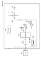
- FIG. 1 is a block diagram of a vehicle control system according to an embodiment
- FIG. It is a figure which shows the rear lamp which is an example of an electrical component.
- a vehicle control system includes an ECU (Electronic Control Unit) and electrical components that operate under the control of the ECU.
- the ECU authenticates the electrical component based on the information stored inside the electrical component, and if the authentication is not passed, the ECU restricts the function of the electrical component.
- the ECU may disable additional functions without restricting functions that are essential for driving.
- the electrical component is a rear lamp
- the ECU may disable the function related to lighting effects. Specifically, the lighting corresponding to the basic driving functions of the automobile such as running, turning, and stopping shall be performed without restriction, and the lighting when the vehicle starts or stops may be restricted. good.
- An ECU constitutes a vehicle control system together with electrical components.
- the ECU includes an interface that communicates with electrical components, a processor that executes software programs, and a non-volatile memory that holds authentication information.
- the processor authenticates the electrical component based on the information stored inside the electrical component, and restricts the function of the electrical component if the authentication is not passed.
- FIG. 1 is a block diagram of a vehicle control system 100 according to an embodiment.
- Vehicle control system 100 is part of an automobile, but its location and function are not limited.
- the vehicle control system 100 includes a vehicle ECU 110, a local ECU 200, and one or more electrical components 300.
- the vehicle ECU 110 is a controller that comprehensively controls the entire vehicle or a portion of the vehicle.
- Vehicle ECU 110 may be a controller also called a BCM (Body Control Module).
- Local ECU 200 controls a portion 300_1 to 300_N of a plurality of electrical components that make up the vehicle. Each of the electrical components 300_1 to 300_N can communicate with the local ECU 200 and operates according to control from the local ECU 200.
- a plurality of electrical components 300_1 to 300_M connected to the local ECU 200 may be related to the same function.
- local ECU 200 may be a lamp ECU that performs lamp-related control
- electrical components 300_1 to 300_M may be lamps.
- electrical component 300_1 may be the left rear lamp
- 300_2 may be the right rear lamp.
- the left and right rear lamps are further divided into a plurality of housings (for example, the vehicle side and the trunk lid side)
- the electrical component 300_1 is the left body side rear lamp
- 300_2 is the left trunk lid side rear lamp
- the electrical component 300_3 may be a right body side rear lamp
- 300_4 may be a right trunk lid side rear lamp.
- a plurality of electrical components 300_1 to 300_M connected to the local ECU 200 may be associated with different functions.
- the local ECU 200 is an integrated ECU that integrally performs control related to lamps, sensors, wipers, etc.
- the electrical components 300_1 to 300_M may be lamps, sensors, and wipers.
- signal lines related to control are indicated by dashed lines. Solid lines represent lines associated with the power supply.
- the local ECU 200 includes a processor 210, a communication circuit 220, a communication circuit 230, a memory 240, a nonvolatile memory 250, and a power supply circuit 260.
- Processor 210 executes software program 252 stored in nonvolatile memory 250, and controls a plurality of electrical components 300_1 to 300_M under its control in accordance with control commands from vehicle ECU 110.
- FIG. 1
- This software program 252 provides the following functions. ⁇ Communication function with vehicle ECU 110 ⁇ Selection of functions (operation modes) of a plurality of electrical components 300 ⁇ Control of operation states of a plurality of electrical components 300
- the communication circuit 220 is an interface that communicates with the vehicle ECU 110 .
- the type of interface is not particularly limited, it may be a vehicle bus such as CAN (Controller Area Network) or LIN (Local Interconnect Network).
- the communication circuit 230 is an interface for communicating with the electrical component 300 .
- the type of this interface is not limited, and may be a serial interface such as I 2 C (Inter IC) or SPI (Serial Peripheral Interface), or an independently designed non-standardized interface. , a vehicle bus.
- the memory 240 stores a program 252 executed by the processor 210 and also stores data generated by the processor 210 .
- the nonvolatile memory 250 stores a program 252 executed by the processor 210 and initial setting values necessary for the operation of the local ECU 200 .
- the power supply circuit 260 supplies power supply voltage to the electrical components 300_1 to 300_M.
- the power supply circuit 260 may be a stabilized power supply, or may be a simple wire or switch that branches the battery voltage.
- the processor 210, communication circuit 220, communication circuit 230, memory 240, and non-volatile memory 250 may be implemented as a microcontroller or may be SoC (System on Chip). Alternatively, they may be separate parts.
- Some of the electrical components 300_1 to 300_M may themselves include processors capable of executing software.
- the processor 210 of the local ECU 200 generates only triggers for starting and stopping operation and supplies them to the active electrical components 300A.
- the active electrical component 300A that has received the trigger to start operation executes a predetermined process based on a software program executed by an internal processor, and stops the process in response to the trigger to stop. That is, the active electrical component 300A actively operates after receiving a trigger to start operation.
- Some of the electrical components 300_1 to 300_M may be composed only of hardware without including a processor capable of executing software.
- a program 252 executed by the processor 210 of the local ECU 200 includes instructions describing the operation sequence of the passive electrical components 300P. The operation of the electrical component 300P is controlled.
- Passive electrical equipment 300P operates passively under the control of local ECU 200 .
- the above is the overall configuration of the vehicle control system 100. Next, authentication will be explained.
- the local ECU 200 authenticates each of the electrical components 300_1 to 300_M.
- the i-th (1 ⁇ i ⁇ M) electrical component 300_i is authenticated based on the authentication information 302 stored in the non-volatile memory 304 inside the electrical component 300_i.
- the method of authentication is not particularly limited. If the authentication is not passed, the local ECU 200 restricts the functions of the electrical component 300_i.
- the manufacturer (supplier) of the electrical component 300 requests approval of the electrical component 300 from the automaker or Tier 1 involved in the design of the vehicle control system 100 at an appropriate time, such as when the design of the electrical component 300 is completed.
- the approver gives appropriate authentication information 302 to the designer of the electrical component 300 if the electrical component 300 meets the specifications and standards.
- the authentication information 302 is shipped while being stored in the non-volatile memory 304 of the electrical component 300 .
- Authentication starts when the local ECU 200 and the electrical component 300 are connected. Authentication may be performed only when connecting for the first time. For example, local ECU 200 requests electrical component 300 to transmit authentication information 302 . The local ECU 200 collates the authentication information 302 received from the electrical component 300 with the authentication information 254 held by itself, and if they match, the authentication is passed, and if they do not match, the authentication is rejected.
- the authentication information 254 of the local ECU 200 may be an ID unique to the model number or series of the local ECU 200 .
- authentication information 254 may be a passcode issued by an organization (organization or alliance) related to the design of vehicle control system 100 . This organization issues the same passcode to the electrical equipment 300 as well.
- Local ECU 200 requests electrical equipment 300 to transmit authentication information 302 .
- Authentication information 254 held by local ECU 200 may include data and protocols for determining the authenticity of authentication information 302 .
- the local ECU 200 may process the authentication information 302 based on the authentication information 302 and determine whether or not to approve the authentication.
- the electrical component 300 operates as designed without restricting the function of the electrical component 300 .
- the local ECU 200 restricts the functions of the electrical component 300 if the authentication is not passed. Restricting includes disabling some or all of the functions, but depending on the type of the electrical component 300 in the automobile, particularly when it relates to the driving function or safety of the vehicle, Disabling the feature completely may not be desirable.
- the local ECU 200 may disable only the additional functions without restricting the functions essential for driving. Additional functions may include functions that do not interfere with driving or ensure safety even without them, functions that are not implemented in other general electrical components 300, and the like.
- the above is the authentication in the vehicle control system 100 and the functional limitation of the electrical component 300 .
- the vehicle control system 100 by restricting the functions of the electrical components 300 that do not pass authentication, that is, the functions of the electrical components 300 that are not assumed by the local ECU 200, it is possible to prevent the electrical components 300 from malfunctioning in an unintended manner. Further, unless the parts manufacturer (supplier) who designs and manufactures the electrical equipment 300 obtains certification, the additional functions are useless. For the parts maker (supplier) that manufactures the parts, the additional functions are useless unless the certification is obtained. Therefore, it is possible to eliminate suppliers who try to manufacture and sell inferior products without certification.
- the present disclosure extends to various devices and methods grasped as block diagrams and circuit diagrams in FIG. 1 or derived from the above description, and is not limited to specific configurations.
- more specific configuration examples and embodiments will be described not to narrow the scope of the present disclosure, but to help understand and clarify the essence and operation of the present disclosure and the present invention.
- FIG. 2 is a diagram showing a rear lamp 400 that is an example of the electrical component 300.
- FIG. 2 is a diagram showing a rear lamp 400 that is an example of the electrical component 300.
- the rear lamp 400 includes a plurality of light emitting elements 410_1 to 410_N and a driver IC (Integrated Circuit) 420.
- the rear lamp 400 is a passive electrical component that does not have a processor (microcontroller).
- the rear lamp 400 may be any one of a brake lamp, a stop lamp, a tail lamp, a turn signal lamp, or a rear combination lamp in which these lamps are integrated.
- the plurality of light emitting elements 410_1 to 410_N are semiconductor light emitting elements such as LEDs (light emitting diodes), organic EL elements, laser diodes, etc. of colors corresponding to the types of lamps.
- a single light emitting element 410 may include multiple LEDs connected in series.
- the driver IC 420 is a functional IC (Integrated Circuit) capable of individually controlling the brightness and lighting/lighting of the plurality of light emitting elements 410_1 to 410_N.
- the driver IC 420 includes a lighting circuit 422, a communication circuit 424, a controller 426, and a nonvolatile memory 428.
- the lighting circuit 422 includes a plurality of current sources CS1-CSN that supply drive currents to the plurality of light-emitting elements 410_1-410_N.
- Rear lamp 400 may further include power supply circuit 450 .
- Power supply circuit 450 is, for example, a DC/DC converter, and steps down or boosts power supply voltage VDD supplied from local ECU 200 to convert it to an appropriate voltage level for light emitting element 410, which is a load. Note that the power supply circuit 450 may be omitted.
- the communication circuit 424 is an interface capable of communicating with the communication circuit 230 of the local ECU 200, and receives from the local ECU 200 a control command including a lighting instruction, a lighting-off instruction, luminance, etc. for the plurality of light emitting elements 410_1 to 410_N.
- Controller 426 controls the plurality of current sources CS1-CSN based on the control commands received by communication circuit 424.
- the nonvolatile memory 428 corresponds to the nonvolatile memory 304 in FIG. 1 and stores the authentication information 302.
- the non-volatile memory 428 may be integrated into the driver IC 420 or externally attached to the driver IC 420 .
- the plurality of light emitting elements 410_1 to 410_N are red LEDs arranged in a row in the horizontal direction and form a stop lamp.
- the stop lamp lights when the brake pedal is depressed. Therefore, vehicle ECU 110 instructs local ECU 200 to turn on the stop lamp when the brake pedal is depressed.
- Local ECU 200 executes a program instruction corresponding to this lighting instruction.
- a control command is inputted to the communication circuit 424 so that the plurality of current sources CS1 to CSN are turned on substantially simultaneously.
- the plurality of light emitting elements 410_1 to 410_N are lit all at once.
- rear lamp 400 turns on a plurality of light emitting elements 410_1 to 410_N according to a predetermined sequence (animation lighting) in response to door unlocking/locking, ignition on, and the like.
- animation lighting is described in a software program executed by the local ECU 200 .
- the local ECU 200 may execute the process for normal lighting of the stop lamp, but may not execute the process for animation lighting.
- the plurality of light emitting elements 410_1-410_N may be amber LEDs arranged in a horizontal line to form a turn signal lamp.
- turn signal lamps sequential winkers have been implemented in some vehicles in recent years.
- the local ECU 200 performs a process (sequential lighting) of sequentially lighting the plurality of light emitting elements 410_1 to 410_N from end to end, and performs the authentication.
- the sequential lighting may be disabled by lighting the plurality of light emitting elements 410_1 to 410_N at the same time.
- the lighting corresponding to the basic driving functions of the automobile such as running, turning, and stopping shall be performed without restriction, and the lighting when the vehicle starts or stops may be restricted. good.
- the rear lamp 400 was a passive electrical component without a microcontroller, ie, a software controllable processor, but the rear lamp 400 may be an active electrical component with a microcontroller. In this case, if the rear lamp 400 has not passed the authentication, the local ECU 200 should not give the rear lamp 400 a trigger to turn on the additional function.
- Modification 2 Although the rear lamp 400 has been described as an example of the electrical component 300 in FIG. 2, it is not limited thereto. Electrical components 300 may be interior lights, fogs, sensors, wipers, and the like.
- the present invention relates to vehicle control systems.
- DESCRIPTION OF SYMBOLS 100... Vehicle control system 110... Vehicle ECU, 200... Local ECU, 210... Processor, 220, 230... Communication circuit, 240... Memory, 250... Non-volatile memory, 260... Power supply circuit, 300... Electrical component, 302... Authentication Information 304 Nonvolatile memory 400 Rear lamp 410 Light emitting element 420 Driver IC 422 Lighting circuit 424 Communication circuit 426 Controller 428 Nonvolatile memory 450 Power supply circuit.
Landscapes
- Engineering & Computer Science (AREA)
- Mechanical Engineering (AREA)
- Lighting Device Outwards From Vehicle And Optical Signal (AREA)
Abstract
車両制御システム(100)は、ローカルECU(200)および電装品(300)を備える。電装品(300)は、ローカルECU(200)の制御下で動作する。ローカルECU(200)は、電装品(300)の内部に格納される情報にもとづいて電装品(300)の認証を行い、認証が通らなかった場合に、ローカルECU(200)は、電装品(300)の機能を制限する。
Description
本発明は、車両制御システムに関する。
自動車は、ECU(Electronic Control Unit)と呼ばれるコントローラを備え、ヘッドランプやリアランプ、ウィンカーやワイパーなどの電装品は、ECUの制御下で動作する。
従来の車両は、車載電装品を、同じ機能に関連する群に分類し、機能毎に共通のECUによって制御するアーキテクチャが採用されていた。たとえば、ヘッドランプやウィンカーなどの灯具は、灯具を管理するECUによって制御されていた。
近年、自動車の高機能化、電子化が進むにしたがい、車両設計のアーキテクチャが変更されつつある。そのひとつとして、機能ごとではなく、ゾーンごとにECUを設け、そのゾーンに含まれる電装品が、そのECUによって集中管理される。つまり、あるゾーンのECUの制御下には、ヘッドランプやウィンカー、ワイパー、センサー、エアコン、エアバッグなどの異なる機能を有する電装品が置かれることとなる。
このアーキテクチャの採用が進むと、ECUとその制御下の電装品の間で、最低限の仕様やプロトコルが定められ、電装品はその仕様、プロトコルに従って設計される将来が想定される。その結果、純正部品の代替として、サードパーティからの代替部品が提供され、ユーザによって選択されることも想定されうる。しかしながら、サードパーティ製の電装品が、それを想定して設計されていないECUの制御下で正しく動作する保証はない。
本開示は係る状況においてされたものであり、そのある態様の例示的な目的のひとつは、信頼性を高めた車両制御システムの提供にある。
本開示のある態様の車両制御システムは、ECU(Electronic Control Unit)と、ECUの制御下で動作する電装品と、を備える。ECUは、電装品の内部に格納される情報にもとづいて電装品の認証を行い、認証を通過しなかった場合に、ECUは電装品の機能を制限する。
本開示の別の態様は、電装品とともに車両制御システムを構成するECU(Electronic Control Unit)である。ECUは、電装品との間で通信を行うインタフェースと、ソフトウェアプログラムを実行するプロセッサと、認証用の情報を保持する不揮発性メモリと、を備える。プロセッサは、電装品の内部に格納される情報にもとづいて電装品の認証を行い、認証を通過しなかった場合に、電装品の機能を制限する。
なお、以上の構成要素を任意に組み合わせたもの、あるいは本開示の表現を、方法、装置などの間で変換したものもまた、本発明の態様として有効である。
本開示のある態様によれば、信頼性を高めることができる。
(実施形態の概要)
本開示のいくつかの例示的な実施形態の概要を説明する。この概要は、後述する詳細な説明の前置きとして、実施形態の基本的な理解を目的として、1つまたは複数の実施形態のいくつかの概念を簡略化して説明するものであり、発明あるいは開示の広さを限定するものではない。この概要は、考えられるすべての実施形態の包括的な概要ではなく、すべての実施形態の重要な要素を特定することも、一部またはすべての態様の範囲を線引きすることも意図していない。便宜上、「一実施形態」は、本明細書に開示するひとつの実施形態(実施例や変形例)または複数の実施形態(実施例や変形例)を指すものとして用いる場合がある。
本開示のいくつかの例示的な実施形態の概要を説明する。この概要は、後述する詳細な説明の前置きとして、実施形態の基本的な理解を目的として、1つまたは複数の実施形態のいくつかの概念を簡略化して説明するものであり、発明あるいは開示の広さを限定するものではない。この概要は、考えられるすべての実施形態の包括的な概要ではなく、すべての実施形態の重要な要素を特定することも、一部またはすべての態様の範囲を線引きすることも意図していない。便宜上、「一実施形態」は、本明細書に開示するひとつの実施形態(実施例や変形例)または複数の実施形態(実施例や変形例)を指すものとして用いる場合がある。
一実施形態に係る車両制御システムは、ECU(Electronic Control Unit)と、ECUの制御下で動作する電装品と、を備える。ECUは、電装品の内部に格納される情報にもとづいて電装品の認証を行い、認証を通過しなかった場合に、ECUは、電装品の機能を制限する。
この構成によると、認証を通過しない、つまりECUが想定していない電装品の機能を制限することにより、電装品が意図しない態様で誤動作するのを防止できる。また電装品を設計、製造する部品メーカ(サプライヤ)にとっては、認証を取らない限りは、追加の機能は無駄になる。したがって認証を取らずに粗悪品を製造、販売しようとするサプライヤを排除することが可能となる。
一実施形態において、ECUは、走行に不可欠な機能は制限せず、付加的な機能を無効化してもよい。
一実施形態において、電装品はリアランプであり、ECUは、演出点灯に関する機能を無効化してもよい。具体的には、走る、曲がる、止まるなどの自動車の基本的な走行機能に対応する点灯については、制限せずに行うこととし、自動車の始動時あるいは停止時の演出点灯などを制限してもよい。
一実施形態に係るECUは、電装品とともに車両制御システムを構成する。ECUは、電装品との間で通信を行うインタフェースと、ソフトウェアプログラムを実行するプロセッサと、認証用の情報を保持する不揮発性メモリと、を備える。プロセッサは、電装品の内部に格納される情報にもとづいて電装品の認証を行い、認証を通過しなかった場合に、電装品の機能を制限する。
(実施形態)
以下、好適な実施の形態について、図面を参照しながら説明する。各図面に示される同一または同等の構成要素、部材、処理には、同一の符号を付するものとし、適宜重複した説明は省略する。また、実施の形態は、開示および発明を限定するものではなく例示であって、実施の形態に記述されるすべての特徴やその組み合わせは、必ずしも開示および発明の本質的なものであるとは限らない。
以下、好適な実施の形態について、図面を参照しながら説明する。各図面に示される同一または同等の構成要素、部材、処理には、同一の符号を付するものとし、適宜重複した説明は省略する。また、実施の形態は、開示および発明を限定するものではなく例示であって、実施の形態に記述されるすべての特徴やその組み合わせは、必ずしも開示および発明の本質的なものであるとは限らない。
図1は、実施形態に係る車両制御システム100のブロック図である。車両制御システム100は、自動車の一部分であるが、その位置や機能は限定されない。
車両制御システム100は、車両ECU110、ローカルECU200、ひとつまたは複数の電装品300を備える。
車両ECU110は、車両全体、あるいは一部分を統括的に制御するコントローラである。車両ECU110は、BCM(Body Control Module)とも称されるコントローラであってもよい。ローカルECU200は、車両を構成する複数の電装品の一部分300_1~300_Nを制御する。電装品300_1~300_Nはそれぞれ、ローカルECU200との間で通信可能であり、ローカルECU200からの制御に応じて動作する。
ローカルECU200に接続される複数の電装品300_1~300_Mは、同じ機能に関連していてもよい。たとえばローカルECU200は、ランプに関連する制御を行うランプECUであり、電装品300_1~300_Mは、ランプであってもよい。たとえば電装品300_1は、左のリアランプ、300_2は右のリアランプであってもよい。左右のリアランプがさらに、複数の筐体(たとえば車両側とトランクリッド側)に分割している場合、電装品300_1は、左のボディ側のリアランプ、300_2は左のトランクリッド側のリアランプ、電装品300_3は、右のボディ側のリアランプ、300_4は右のトランクリッド側のリアランプであってもよい。
ローカルECU200に接続される複数の電装品300_1~300_Mは、異なる機能に関連していてもよい。たとえばローカルECU200は、ランプやセンサ、ワイパーなどに関連する制御を統合的に行う統合ECUであり、電装品300_1~300_Mは、ランプ、センサ、ワイパーであってもよい。
図1において、制御に関連する信号線は破線で示す。実線は電源に関連するラインを表す。
ローカルECU200は、プロセッサ210、通信回路220、通信回路230、メモリ240、不揮発性メモリ250、電源回路260を備える。プロセッサ210は、不揮発性メモリ250に格納されるソフトウェアプログラム252を実行し、車両ECU110からの制御指令に応じて、その配下にある複数の電装品300_1~300_Mを制御する。
このソフトウェアプログラム252によって、以下の機能が提供される。
・車両ECU110との通信機能
・複数の電装品300の機能(動作モード)の選択
・複数の電装品300の動作状態の制御
・車両ECU110との通信機能
・複数の電装品300の機能(動作モード)の選択
・複数の電装品300の動作状態の制御
通信回路220は、車両ECU110との間で通信を行うインタフェースである。インタフェースの種類は特に限定されないが、CAN(Controller Area Network)やLIN(Local Interconnect Network)などのビークルバスであってもよい。
通信回路230は、電装品300との間で通信を行うためのインタフェースである。このインタフェースの種類は限定されず、I2C(Inter IC)やSPI(Serial Peripheral Interface)などのシリアルインタフェースであってもよいし、独自に設計された標準化されていないインタフェースであってもよいし、ビークルバスであってもよい。
メモリ240は、プロセッサ210が実行するプログラム252が格納され、またプロセッサ210が生成するデータが格納される。
不揮発性メモリ250には、プロセッサ210が実行するプログラム252や、ローカルECU200の動作に必要な初期設定値が格納される。
電源回路260は、電装品300_1~300_Mに電源電圧を供給する。電源回路260は、安定化電源であってもよいし、バッテリ電圧を分岐する単なる配線やスイッチであってもよい。
ローカルECU200のうち、プロセッサ210、通信回路220、通信回路230、メモリ240、不揮発性メモリ250は、マイクロコントローラとして実装されてもよいし、SoC(System on Chip)であってもよい。あるいはこれらは別々の部品であってもよい。
電装品300_1~300_Mのいくつかは、それ自身がソフトウェアを実行可能なプロセッサを含んでいてもよい。こうした電装品(以下、アクティブ電装品という)300Aに対しては、ローカルECU200のプロセッサ210は、動作開始や停止のトリガーのみを発生し、アクティブ電装品300Aに供給する。動作開始のトリガーを受けたアクティブ電装品300Aは、内部のプロセッサが実行するソフトウェアプログラムにもとづいて、所定の処理を実行し、停止のトリガーに応答して処理を停止する。つまりアクティブ電装品300Aは、動作開始のトリガーを受けた後は、能動的に動作する。
電装品300_1~300_Mのいくつかは、ソフトウェアを実行可能なプロセッサを含まず、ハードウェアのみで構成されていてもよい。こうした電装品(以下、パッシブ電装品という)300Pに対しては、ローカルECU200のプロセッサ210が実行するプログラム252に、パッシブ電装品300Pの動作シーケンスを記述する命令が記述されており、プロセッサ210によってパッシブ電装品300Pの動作が制御される。パッシブ電装品300Pは、ローカルECU200の制御下で受動的に動作する。
以上が車両制御システム100の全体構成である。続いて認証について説明する。
ローカルECU200は、電装品300_1~300_Mそれぞれについて認証を行う。i番目(1≦i≦M)の電装品300_iは、電装品300_iの内部の不揮発性メモリ304に格納される認証情報302にもとづいて行われる。認証の方式は特に限定されない。認証を通過しなかった場合に、ローカルECU200は、電装品300_iの機能を制限する。
たとえば電装品300のメーカ(サプライヤ)は、電装品300の設計完了時など、適切な時期に、車両制御システム100の設計に係わる自動車メーカやティア1に対して、電装品300の承認を求める。承認者は、電装品300が仕様や基準を満たしている場合、電装品300の設計者に適切な認証情報302を与える。認証情報302は、電装品300の不揮発性メモリ304に格納された状態で出荷される。
ローカルECU200と電装品300が接続されると、認証が開始される。認証は、初回の接続時のみ行ってもよい。たとえば、ローカルECU200は、電装品300に対して、認証情報302の送信を要求する。ローカルECU200は、電装品300から受信した認証情報302を、自信が保持する認証情報254と照合し、一致したときに認証通過とし、不一致の場合には認証を拒否する。
たとえばローカルECU200の認証情報254は、ローカルECU200の型番やシリーズに固有のIDであってもよい。あるいは認証情報254は、車両制御システム100の設計に関連する団体(組織やアライアンス)が発行するパスコードであってもよい。この団体は、電装品300に対しても、同じパスコードを発行する。
認証の別の例を説明する。ローカルECU200は、電装品300に対して、認証情報302の送信を要求する。ローカルECU200が保持する認証情報254は、認証情報302の真偽を判定するためのデータやプロトコルを含んでいてもよい。ローカルECU200は、認証情報302を、認証情報302にもとづいて処理し、認証の可否を決定してもよい。
ローカルECU200は、認証を通過した場合には、電装品300の機能を制限せずに、電装品300の設計通りに動作させる。
一方、ローカルECU200は、認証を通過しなかった場合には、電装品300の機能を制限する。制限するとは、一部あるいは全部の機能を無効化することを含むが、自動車において、電装品300の種類によっては、特にそれが車両の走行機能や安全性に係わるものである場合には、その機能を完全に無効化することは好ましくない場合がある。
そこでローカルECU200は、走行に不可欠な機能は制限せず、付加的な機能のみを無効化してもよい。付加的な機能とは、それがなくても走行や安全性の確保に支障がない機能、他の一般的な電装品300には実装されていない機能などを含みうる。
以上が車両制御システム100における認証と電装品300の機能制限である。
この車両制御システム100によれば、認証を通過しない、つまりローカルECU200が想定していない電装品300の機能を制限することにより、電装品300が意図しない態様で誤動作するのを防止できる。また電装品300を設計、製造する部品メーカ(サプライヤ)は、認証を取らない限りは、追加の機能は無駄になる。製造する部品メーカ(サプライヤ)にとっては、認証を取らない限りは、追加の機能は無駄になる。したがって認証を取らずに粗悪品を製造、販売しようとするサプライヤを排除することが可能となる。
本開示は、図1のブロック図や回路図として把握され、あるいは上述の説明から導かれるさまざまな装置、方法に及ぶものであり、特定の構成に限定されるものではない。以下、本開示の範囲を狭めるためではなく、本開示や本発明の本質や動作の理解を助け、またそれらを明確化するために、より具体的な構成例や実施例を説明する。
図2は、電装品300の一例であるリアランプ400を示す図である。
リアランプ400は、複数の発光素子410_1~410_NおよびドライバIC(Integrated Circuit)420を備える。つまりリアランプ400は、プロセッサ(マイクロコントローラ)を有しないパッシブ電装品である。リアランプ400は、ブレーキランプ、ストップランプ、テールランプ、ターンシグナルランプのいずれかであってもよいし、それらが統合されたリアコンビネーションランプであってもよい。
複数の発光素子410_1~410_Nは、ランプの種類に応じた色のLED(発光ダイオード)、有機EL素子、レーザダイオードなどの半導体発光素子である。1個の発光素子410は、直列に接続された複数のLEDを含んでもよい。
ドライバIC420は、複数の発光素子410_1~発光素子410_Nの輝度および点消灯を個別に制御可能な機能IC(Integrated Circuit)である。
ドライバIC420は、点灯回路422、通信回路424、コントローラ426、不揮発性メモリ428を備える。点灯回路422は、複数の発光素子410_1~410_Nに駆動電流を供給する複数の電流源CS1~CSNを含む。
リアランプ400は、電源回路450をさらに備えてもよい。電源回路450は、たとえばDC/DCコンバータであり、ローカルECU200から供給される電源電圧VDDを降圧あるいは昇圧し、負荷である発光素子410に対して適切な電圧レベルに変換する。なお電源回路450は省略することもできる。
通信回路424は、ローカルECU200の通信回路230との間で通信可能なインタフェースであり、ローカルECU200から、複数の発光素子410_1~410_Nの点灯指示や消灯指示、輝度などを含む制御指令を受信する。コントローラ426は通信回路424が受信した制御指令にもとづいて、複数の電流源CS1~CSNを制御する。
不揮発性メモリ428は、図1の不揮発性メモリ304に相当し、認証情報302を格納する。不揮発性メモリ428は、ドライバIC420に集積化されてもよいし、ドライバIC420に外付けされてもよい。
本実施例において、複数の発光素子410_1~410_Nは、水平方向に一列に並べられた赤色のLEDあり、ストップランプを形成するものとする。通常の走行中において、ストップランプはブレーキペダルが踏まれると点灯する。したがって、車両ECU110は、ブレーキペダルが踏まれると、ローカルECU200に対してストップランプの点灯を指示する。ローカルECU200は、この点灯指示に対応するプログラムの命令を実行する。その結果、複数の電流源CS1~CSNが実質的に同時に点灯するような制御指令が、通信回路424に入力される。これにより、複数の発光素子410_1~410_Nが一斉に点灯する。
近年、車両用灯具を利用した演出がトレンドとなっている。たとえばリアランプ400は、ドアの開錠や施錠、イグニッションオンなどに応答して、複数の発光素子410_1~発光素子410_Nを所定のシーケンスにしたがって点灯させる(アニメーション点灯)。ただし、リアランプ400自体には、マイクロコントローラは搭載されていないため、アニメーション点灯に関する処理は、ローカルECU200が実行するソフトウェアプログラムに記述されている。
この場合において、ローカルECU200は、リアランプ(ストップランプ)400が認証を通過していない場合、ストップランプの通常点灯に関する処理は実行するが、アニメーション点灯に関する処理は実行しないこととしてもよい。
他の実施例において、複数の発光素子410_1~410_Nは、水平方向に一列に並べられたアンバーのLEDあり、ターンシグナルランプを形成してもよい。ターンシグナルランプについて、近年、シーケンシャルウィンカーが一部の車両に実装されている。ローカルECU200は、リアランプ(ターンシグナルランプ)400が認証を通過している場合には、複数の発光素子410_1~410_Nを端から端に順番に点灯していく処理(シーケンシャル点灯)を実行し、認証を通過していない場合には、複数の発光素子410_1~410_Nを同時に点灯するようにして、シーケンシャル点灯を無効化してもよい。
具体的には、走る、曲がる、止まるなどの自動車の基本的な走行機能に対応する点灯については、制限せずに行うこととし、自動車の始動時あるいは停止時の演出点灯などを制限してもよい。
(変形例)
上述した実施形態は例示であり、それらの各構成要素や各処理プロセスの組み合わせにいろいろな変形例が可能なことが当業者に理解される。以下、こうした変形例について説明する。
上述した実施形態は例示であり、それらの各構成要素や各処理プロセスの組み合わせにいろいろな変形例が可能なことが当業者に理解される。以下、こうした変形例について説明する。
(変形例1)
図2の例では、リアランプ400は、マイクロコントローラ、つまりソフトウェア制御可能なプロセッサを備えないパッシブ電装品であったが、リアランプ400は、マイクロコントローラを備えるアクティブ電装品であってもよい。この場合、ローカルECU200は、リアランプ400が認証を通過していない場合、付加機能に関する点灯のトリガーを、リアランプ400に対して与えないようにすればよい。
図2の例では、リアランプ400は、マイクロコントローラ、つまりソフトウェア制御可能なプロセッサを備えないパッシブ電装品であったが、リアランプ400は、マイクロコントローラを備えるアクティブ電装品であってもよい。この場合、ローカルECU200は、リアランプ400が認証を通過していない場合、付加機能に関する点灯のトリガーを、リアランプ400に対して与えないようにすればよい。
(変形例2)
図2では電装品300の例としてリアランプ400を説明したが、その限りでない。電装品300は、室内灯、フォグ、センサー、ワイパーなどであってもよい。
図2では電装品300の例としてリアランプ400を説明したが、その限りでない。電装品300は、室内灯、フォグ、センサー、ワイパーなどであってもよい。
実施形態は例示であり、それらの各構成要素や各処理プロセスの組み合わせにさまざまな変形例が存在すること、またそうした変形例も本開示または本発明の範囲に含まれることは当業者に理解されるところである。
本発明は、車両制御システムに関する。
100…車両制御システム、110…車両ECU、200…ローカルECU、210…プロセッサ、220,230…通信回路、240…メモリ、250…不揮発性メモリ、260…電源回路、300…電装品、302…認証情報、304…不揮発性メモリ、400…リアランプ、410…発光素子、420…ドライバIC、422…点灯回路、424…通信回路、426…コントローラ、428…不揮発性メモリ、450…電源回路。
Claims (4)
- ECU(Electronic Control Unit)と、
前記ECUの制御下で動作する電装品と、
を備え、
前記ECUは、前記電装品の内部に格納される情報にもとづいて電装品の認証を行い、認証が通らなかった場合に、前記ECUは、前記電装品の機能を制限することを特徴とする車両制御システム。 - 前記ECUは、走行に不可欠な機能は制限せず、付加的な機能を制限することを特徴とする請求項1に記載の車両制御システム。
- 前記電装品はリアランプであり、前記ECUは、演出点灯に関する機能を制限することを特徴とする請求項2に記載の車両制御システム。
- 電装品とともに車両制御システムを構成するECU(Electronic Control Unit)であって、
前記電装品との間で通信を行うインタフェースと、
ソフトウェアプログラムを実行するプロセッサと、
認証用の情報を保持する不揮発性メモリと、
を備え、
前記プロセッサは、前記電装品の内部に格納される情報にもとづいて前記電装品の認証を行い、認証が通らなかった場合に、前記電装品の機能を制限することを特徴とするECU。
Priority Applications (1)
| Application Number | Priority Date | Filing Date | Title |
|---|---|---|---|
| JP2023530417A JPWO2022265083A1 (ja) | 2021-06-17 | 2022-06-16 |
Applications Claiming Priority (2)
| Application Number | Priority Date | Filing Date | Title |
|---|---|---|---|
| JP2021-100924 | 2021-06-17 | ||
| JP2021100924 | 2021-06-17 |
Publications (1)
| Publication Number | Publication Date |
|---|---|
| WO2022265083A1 true WO2022265083A1 (ja) | 2022-12-22 |
Family
ID=84527536
Family Applications (1)
| Application Number | Title | Priority Date | Filing Date |
|---|---|---|---|
| PCT/JP2022/024221 Ceased WO2022265083A1 (ja) | 2021-06-17 | 2022-06-16 | 車両制御システムおよびecu |
Country Status (2)
| Country | Link |
|---|---|
| JP (1) | JPWO2022265083A1 (ja) |
| WO (1) | WO2022265083A1 (ja) |
Citations (3)
| Publication number | Priority date | Publication date | Assignee | Title |
|---|---|---|---|---|
| JP2005316229A (ja) * | 2004-04-30 | 2005-11-10 | Fuji Xerox Co Ltd | 部品判別装置、部品着脱式装置、および画像形成装置 |
| JP2012050268A (ja) * | 2010-08-27 | 2012-03-08 | Denso Corp | 電池管理システム |
| JP2019001311A (ja) * | 2017-06-15 | 2019-01-10 | 株式会社小糸製作所 | 発光駆動回路、車両用灯具 |
-
2022
- 2022-06-16 WO PCT/JP2022/024221 patent/WO2022265083A1/ja not_active Ceased
- 2022-06-16 JP JP2023530417A patent/JPWO2022265083A1/ja active Pending
Patent Citations (3)
| Publication number | Priority date | Publication date | Assignee | Title |
|---|---|---|---|---|
| JP2005316229A (ja) * | 2004-04-30 | 2005-11-10 | Fuji Xerox Co Ltd | 部品判別装置、部品着脱式装置、および画像形成装置 |
| JP2012050268A (ja) * | 2010-08-27 | 2012-03-08 | Denso Corp | 電池管理システム |
| JP2019001311A (ja) * | 2017-06-15 | 2019-01-10 | 株式会社小糸製作所 | 発光駆動回路、車両用灯具 |
Also Published As
| Publication number | Publication date |
|---|---|
| JPWO2022265083A1 (ja) | 2022-12-22 |
Similar Documents
| Publication | Publication Date | Title |
|---|---|---|
| CN103797759B (zh) | 车载网关装置及车辆用通信系统 | |
| CN103269907B (zh) | 线束组件和照明单元 | |
| ES2219626T3 (es) | Faro de alumbrado o señalizacion para vehiculo y sistema de alumbrado o señalizacion equipado con al menos uno de dichos faros. | |
| JP7794233B2 (ja) | ソフトウェア更新装置、ソフトウェアの更新方法及びソフトウェア更新処理プログラム | |
| WO2017062691A9 (en) | Smart lighting system for a vehicle | |
| JP2014080143A (ja) | 車両用ランプの点灯制御システム | |
| JP2009090719A (ja) | イモビライザ装置 | |
| CN216659812U (zh) | 一种车身域控制器及汽车 | |
| JP6389158B2 (ja) | 車両用ワイヤハーネス | |
| KR20210040500A (ko) | 전기 모터를 구비한 자동차 및 그를 위한 충전 상태 표시 방법 | |
| US20240113911A1 (en) | Vehicle control system | |
| WO2022265083A1 (ja) | 車両制御システムおよびecu | |
| CN113799686A (zh) | 一种车灯迎宾方法和系统 | |
| CN107074194B (zh) | 用于控制机动车的至少一个功能构件的运行的方法和机动车 | |
| CN110001552B (zh) | 车载控制器 | |
| US12583384B2 (en) | System and method for controlling a vehicle condition check light using a DWL mode | |
| US12265810B2 (en) | Vehicle control system and program writing method | |
| US20230347839A1 (en) | Vehicle control system, program writing method, and vehicle manufacturing method | |
| EP1884405B1 (en) | An electronic control unit, control method and computer program | |
| US10622734B2 (en) | Method of manufacturing programmable controller | |
| JP2007235349A (ja) | バス通信システム | |
| CN101782749B (zh) | 控制系统、控制装置 | |
| US10220780B2 (en) | Lighting module for vehicle | |
| US12022591B1 (en) | Lamp assemblies and methods for controlling operating parameters of light sources | |
| KR102313839B1 (ko) | 자동차 실내무드조명용 RGB LED의 Full Rank 사용을 위한 화이트 밸런스 제어방법 |
Legal Events
| Date | Code | Title | Description |
|---|---|---|---|
| 121 | Ep: the epo has been informed by wipo that ep was designated in this application |
Ref document number: 22825071 Country of ref document: EP Kind code of ref document: A1 |
|
| WWE | Wipo information: entry into national phase |
Ref document number: 2023530417 Country of ref document: JP |
|
| NENP | Non-entry into the national phase |
Ref country code: DE |
|
| 122 | Ep: pct application non-entry in european phase |
Ref document number: 22825071 Country of ref document: EP Kind code of ref document: A1 |