WO2022264530A1 - 冷却液循環ユニット及びその制御方法並びにプログラム - Google Patents
冷却液循環ユニット及びその制御方法並びにプログラム Download PDFInfo
- Publication number
- WO2022264530A1 WO2022264530A1 PCT/JP2022/007654 JP2022007654W WO2022264530A1 WO 2022264530 A1 WO2022264530 A1 WO 2022264530A1 JP 2022007654 W JP2022007654 W JP 2022007654W WO 2022264530 A1 WO2022264530 A1 WO 2022264530A1
- Authority
- WO
- WIPO (PCT)
- Prior art keywords
- cooling
- liquid
- amount
- unit
- flow rate
- Prior art date
- Legal status (The legal status is an assumption and is not a legal conclusion. Google has not performed a legal analysis and makes no representation as to the accuracy of the status listed.)
- Ceased
Links
Images






Classifications
-
- H—ELECTRICITY
- H05—ELECTRIC TECHNIQUES NOT OTHERWISE PROVIDED FOR
- H05K—PRINTED CIRCUITS; CASINGS OR CONSTRUCTIONAL DETAILS OF ELECTRIC APPARATUS; MANUFACTURE OF ASSEMBLAGES OF ELECTRICAL COMPONENTS
- H05K7/00—Constructional details common to different types of electric apparatus
- H05K7/20—Modifications to facilitate cooling, ventilating, or heating
- H05K7/20218—Modifications to facilitate cooling, ventilating, or heating using a liquid coolant without phase change in electronic enclosures
- H05K7/20281—Thermal management, e.g. liquid flow control
-
- H—ELECTRICITY
- H10—SEMICONDUCTOR DEVICES; ELECTRIC SOLID-STATE DEVICES NOT OTHERWISE PROVIDED FOR
- H10W—GENERIC PACKAGES, INTERCONNECTIONS, CONNECTORS OR OTHER CONSTRUCTIONAL DETAILS OF DEVICES COVERED BY CLASS H10
- H10W40/00—Arrangements for thermal protection or thermal control
- H10W40/30—Arrangements for thermal protection or thermal control wherein the packaged device is completely immersed in a fluid other than air, e.g. immersed in a cryogenic fluid
-
- G—PHYSICS
- G06—COMPUTING OR CALCULATING; COUNTING
- G06F—ELECTRIC DIGITAL DATA PROCESSING
- G06F1/00—Details not covered by groups G06F3/00 - G06F13/00 and G06F21/00
- G06F1/16—Constructional details or arrangements
- G06F1/20—Cooling means
-
- G—PHYSICS
- G06—COMPUTING OR CALCULATING; COUNTING
- G06F—ELECTRIC DIGITAL DATA PROCESSING
- G06F1/00—Details not covered by groups G06F3/00 - G06F13/00 and G06F21/00
- G06F1/16—Constructional details or arrangements
- G06F1/20—Cooling means
- G06F1/206—Cooling means comprising thermal management
-
- H—ELECTRICITY
- H05—ELECTRIC TECHNIQUES NOT OTHERWISE PROVIDED FOR
- H05K—PRINTED CIRCUITS; CASINGS OR CONSTRUCTIONAL DETAILS OF ELECTRIC APPARATUS; MANUFACTURE OF ASSEMBLAGES OF ELECTRICAL COMPONENTS
- H05K7/00—Constructional details common to different types of electric apparatus
- H05K7/20—Modifications to facilitate cooling, ventilating, or heating
-
- H—ELECTRICITY
- H05—ELECTRIC TECHNIQUES NOT OTHERWISE PROVIDED FOR
- H05K—PRINTED CIRCUITS; CASINGS OR CONSTRUCTIONAL DETAILS OF ELECTRIC APPARATUS; MANUFACTURE OF ASSEMBLAGES OF ELECTRICAL COMPONENTS
- H05K7/00—Constructional details common to different types of electric apparatus
- H05K7/20—Modifications to facilitate cooling, ventilating, or heating
- H05K7/20009—Modifications to facilitate cooling, ventilating, or heating using a gaseous coolant in electronic enclosures
- H05K7/20136—Forced ventilation, e.g. by fans
-
- H—ELECTRICITY
- H05—ELECTRIC TECHNIQUES NOT OTHERWISE PROVIDED FOR
- H05K—PRINTED CIRCUITS; CASINGS OR CONSTRUCTIONAL DETAILS OF ELECTRIC APPARATUS; MANUFACTURE OF ASSEMBLAGES OF ELECTRICAL COMPONENTS
- H05K7/00—Constructional details common to different types of electric apparatus
- H05K7/20—Modifications to facilitate cooling, ventilating, or heating
- H05K7/20009—Modifications to facilitate cooling, ventilating, or heating using a gaseous coolant in electronic enclosures
- H05K7/20209—Thermal management, e.g. fan control
-
- H—ELECTRICITY
- H05—ELECTRIC TECHNIQUES NOT OTHERWISE PROVIDED FOR
- H05K—PRINTED CIRCUITS; CASINGS OR CONSTRUCTIONAL DETAILS OF ELECTRIC APPARATUS; MANUFACTURE OF ASSEMBLAGES OF ELECTRICAL COMPONENTS
- H05K7/00—Constructional details common to different types of electric apparatus
- H05K7/20—Modifications to facilitate cooling, ventilating, or heating
- H05K7/20218—Modifications to facilitate cooling, ventilating, or heating using a liquid coolant without phase change in electronic enclosures
- H05K7/20236—Modifications to facilitate cooling, ventilating, or heating using a liquid coolant without phase change in electronic enclosures by immersion
-
- H—ELECTRICITY
- H05—ELECTRIC TECHNIQUES NOT OTHERWISE PROVIDED FOR
- H05K—PRINTED CIRCUITS; CASINGS OR CONSTRUCTIONAL DETAILS OF ELECTRIC APPARATUS; MANUFACTURE OF ASSEMBLAGES OF ELECTRICAL COMPONENTS
- H05K7/00—Constructional details common to different types of electric apparatus
- H05K7/20—Modifications to facilitate cooling, ventilating, or heating
- H05K7/20218—Modifications to facilitate cooling, ventilating, or heating using a liquid coolant without phase change in electronic enclosures
- H05K7/20263—Heat dissipaters releasing heat from coolant
-
- H—ELECTRICITY
- H05—ELECTRIC TECHNIQUES NOT OTHERWISE PROVIDED FOR
- H05K—PRINTED CIRCUITS; CASINGS OR CONSTRUCTIONAL DETAILS OF ELECTRIC APPARATUS; MANUFACTURE OF ASSEMBLAGES OF ELECTRICAL COMPONENTS
- H05K7/00—Constructional details common to different types of electric apparatus
- H05K7/20—Modifications to facilitate cooling, ventilating, or heating
- H05K7/20218—Modifications to facilitate cooling, ventilating, or heating using a liquid coolant without phase change in electronic enclosures
- H05K7/20272—Accessories for moving fluid, for expanding fluid, for connecting fluid conduits, for distributing fluid, for removing gas or for preventing leakage, e.g. pumps, tanks or manifolds
-
- Y—GENERAL TAGGING OF NEW TECHNOLOGICAL DEVELOPMENTS; GENERAL TAGGING OF CROSS-SECTIONAL TECHNOLOGIES SPANNING OVER SEVERAL SECTIONS OF THE IPC; TECHNICAL SUBJECTS COVERED BY FORMER USPC CROSS-REFERENCE ART COLLECTIONS [XRACs] AND DIGESTS
- Y02—TECHNOLOGIES OR APPLICATIONS FOR MITIGATION OR ADAPTATION AGAINST CLIMATE CHANGE
- Y02D—CLIMATE CHANGE MITIGATION TECHNOLOGIES IN INFORMATION AND COMMUNICATION TECHNOLOGIES [ICT], I.E. INFORMATION AND COMMUNICATION TECHNOLOGIES AIMING AT THE REDUCTION OF THEIR OWN ENERGY USE
- Y02D10/00—Energy efficient computing, e.g. low power processors, power management or thermal management
Definitions
- the present disclosure relates to a cooling liquid circulation unit that circulates cooling liquid in an immersion bath, a control method thereof, and a program.
- Patent Document 1 discloses a liquid immersion cooling system that cools electronic devices such as servers and storages by immersing them in a cooling liquid in a data center. Specifically, in Patent Document 1, the cooling liquid heated by cooling the electronic device in the cooling tank is cooled in the heat exchanger, and the cooled cooling liquid is returned to the cooling tank to cool the cooling liquid.
- a circulating liquid immersion cooling system is disclosed.
- the amount of heat generated by an electronic device is not constant but changes. Therefore, it is desirable to change the cooling conditions according to the amount of heat generated.
- the present disclosure has been made in view of such circumstances, and aims to provide a cooling liquid circulation unit, a control method thereof, and a program that can set cooling conditions in consideration of the amount of heat generated by an electronic device. aim.
- a first aspect of the present disclosure is a cooling liquid circulation unit that circulates a cooling liquid in a liquid immersion bath for cooling a plurality of electronic devices by immersing them in the cooling liquid, wherein the cooling liquid is supplied to the liquid immersion bath.
- a flow rate adjustment section provided in a coolant circulation path to be circulated, a heat exchanger provided in the coolant circulation path and exchanging heat between the coolant and the cooling medium, and a coolant circulation unit control section
- the cooling liquid circulation unit control section includes a mode selection section that selects one of a plurality of cooling modes, a calculation section that calculates a required cooling amount based on parameters related to operating states of the plurality of electronic devices, and and a cooling condition setting unit that sets a target value of a parameter related to the flow rate of the cooling liquid based on the selected cooling mode and the required cooling amount.
- a second aspect of the present disclosure is a control method for a cooling liquid circulation unit that circulates cooling liquid in a liquid immersion tank that cools a plurality of electronic devices by immersing them in the cooling liquid, the cooling liquid circulation unit comprising: a flow rate adjusting unit provided in a cooling liquid circulation path that circulates the cooling liquid in the liquid immersion tank; and a heat exchanger that is provided in the cooling liquid circulation path and exchanges heat between the cooling liquid and the cooling medium.
- the control method comprises the steps of: selecting one of a plurality of cooling modes; calculating a required cooling amount based on parameters relating to operating states of the plurality of electronic devices; and setting a target value of a parameter relating to the flow rate of the cooling liquid based on the cooling mode and the required cooling amount.
- a third aspect of the present disclosure is a program for causing a computer to function as the coolant circulation unit control section.
- a fourth aspect of the present disclosure is a liquid immersion cooling system including the cooling liquid circulation unit and the liquid immersion bath.
- Cooling conditions can be set in consideration of the amount of heat generated by electronic devices.
- FIG. 1 is a system configuration diagram schematically showing the system configuration of a liquid immersion cooling system according to a first embodiment of the present disclosure
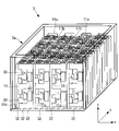
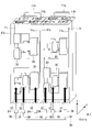
- FIG. FIG. 2 is a perspective view showing a concrete example of the inside of the liquid immersion bath of FIG. 1
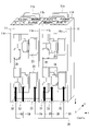
- FIG. 3 is a perspective view showing the flow of cooling liquid with respect to each substrate in FIG. 2
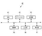
- It is a figure showing an example of hardware constitutions of a system control device concerning a 1st embodiment of this indication.
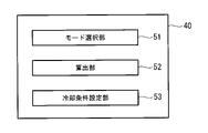
- 2 is a functional block diagram showing an example of functions provided by a system control device according to the first embodiment of the present disclosure
- FIG. 4 is a flow chart showing an example of a procedure of a control method for a coolant circulation system realized by a system control device according to the first embodiment of the present disclosure
- 4 is a flow chart showing an example of a procedure of a control method for a coolant circulation system realized by a system control device according to the first embodiment of the present disclosure
- FIG. 7 is a functional block diagram showing an example of functions provided by a system control device according to the second embodiment of the present disclosure
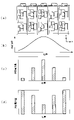
- FIG. 10 is a diagram for explaining a deviation between power consumption distribution and cooling efficiency distribution in the system control device according to the second embodiment of the present disclosure
- FIG. 10 is a diagram showing an example of temporal changes in calculation jobs given to each substrate (first substrate to fifth substrate);
- FIG. 12 is a perspective view showing the flow of cooling liquid to each substrate in the liquid immersion cooling system according to the third embodiment of the present disclosure
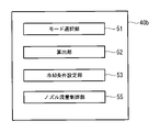
- FIG. 11 is a functional block diagram showing an example of functions provided by a system control device according to a third embodiment of the present disclosure
- FIG. 12 is a functional block diagram showing an example of functions provided by a cooling unit control section according to the fourth embodiment of the present disclosure
- FIG. 11 is a functional block diagram showing an example of functions provided by a coolant circulation unit control section according to a fifth embodiment of the present disclosure
- FIG. 1 is a schematic diagram showing a schematic configuration of a liquid immersion cooling system 1 according to this embodiment.
- the liquid immersion cooling system 1 includes a liquid immersion tank (container) 3 and a cooling liquid circulation system 6 .
- the liquid immersion bath 3 is a bottomed container in which the cooling liquid Lq is stored.
- the liquid immersion tank 3 has a bottomed main body 3a having side walls 3b on four sides, and an opening/closing lid 3c provided on the upper surface of the main body 3a.
- an electrically insulating liquid such as a silicone oil is used as the cooling liquid Lq.
- the cooling liquid Lq is filled up to a height such that the entire substrate 11 placed in the main body 3a of the liquid immersion bath 3 is submerged.
- the opening/closing lid 3c opens and closes by rotating around the upper end of the side wall portion 3b.
- the opening/closing lid 3 c is opened when the substrate 11 is installed in or removed from the main body 3 a of the liquid immersion bath 3 or during maintenance of the liquid immersion bath 3 .
- the opening/closing lid 3c is closed during normal use (during cooling of the substrate 11).
- a plurality of electronic devices are immersed in the main body 3a of the liquid immersion tank 3 in such a manner that they are mounted on each substrate 11, for example.
- Examples of electronic devices include electronic computers (servers) and storages.
- FIG. 1 shows a case where a plurality of substrates 11 are installed in the liquid immersion tank 3 .
- the substrates 11 are, for example, substrates that constitute a server, and are arranged at predetermined intervals with their longitudinal directions oriented in the vertical direction.
- the layout of the substrates and the manner in which the electronic device is mounted are not limited to this.
- the cooling liquid circulation system 6 circulates the cooling liquid to the liquid immersion bath 3 . Specifically, the cooling liquid circulation system 6 cools the cooling liquid heated by cooling the electronic device mounted on the substrate 11 in the liquid immersion bath 3 by the heat exchanger 17, and the cooling liquid after cooling is cooled as a liquid. By returning to the immersion bath 3, the coolant is circulated.
- the coolant circulation system 6 includes a coolant circulation unit 5, a cooling unit 7, and a system control device 40 (see FIG. 4), which will be described later.
- the coolant circulation unit 5 includes a coolant circulation path, a pump 19 and a heat exchanger 17 .
- the coolant circulation path includes, for example, a liquid return pipe 15 , a coolant discharge pipe 21 , and a liquid feed pipe 13 .
- a pump 19 and a heat exchanger 17 are provided in the coolant circuit.
- the cooling liquid circulation unit 5 is connected to the liquid immersion bath 3 via, for example, a liquid sending pipe 13 and a liquid returning pipe 15 .
- a downstream end 13 a of the liquid feed pipe 13 is connected to the side wall portion 3 b of the liquid immersion tank 3 .
- An upstream end 13 b of the liquid feed pipe 13 is connected to a heat exchanger 17 installed inside the coolant circulation unit 5 .
- An upstream end 15 a of the liquid return pipe 15 is connected to the side wall portion 3 b of the liquid immersion tank 3 .
- a downstream end 15 b of the liquid return pipe 15 is connected to a pump (first flow rate adjusting section) 19 for circulating the cooling liquid installed inside the cooling liquid circulation unit 5 .
- the heat exchanger 17 exchanges heat between the coolant supplied from the cooling unit 7 and the coolant supplied from the pump 19 through the coolant discharge pipe 21 .
- the coolant is cooled by exchanging heat with cooling water in the heat exchanger 17 .
- the pump 19 is driven by, for example, an electric motor, and the discharge amount is controlled by a system control device (see FIG. 4), which will be described later.
- the coolant circulation unit 5 is provided with temperature sensors (not shown) for respectively detecting the temperature of the coolant flowing into the heat exchanger 17 and the temperature of the outlet of the coolant sent out from the heat exchanger 17. .
- the coolant circulation unit 5 may be provided with a flow rate sensor for detecting the coolant flow rate.
- the cooling unit 7 includes a cooling water circulation path through which cooling water (cooling medium) circulates.
- the cooling water circulation path includes, for example, a cooling water supply pipe 25 and a cooling water return pipe 26 .
- a pump (second flow control unit) 28 for circulating the cooling water is provided in the cooling water circulation path.
- the pump 28 is driven by, for example, an electric motor, and the discharge amount is controlled by a system control device (see FIG. 4), which will be described later.
- the cooling unit 7 includes a fan (cooling section) 23, and the fan 23 takes in outside air for cooling.
- the start/stop and rotation speed of the fan 23 are controlled by a system control device (see FIG. 4), which will be described later.
- the cooling water circulating in the cooling water circuit is cooled by exchanging heat with outside air taken in by the fan 23 .
- the cooling water cooled by heat exchange with the outside air in the cooling unit 7 is supplied to the heat exchanger 17 via the cooling water supply pipe 25 .
- the cooling water that has undergone heat exchange in the heat exchanger 17 is returned to the cooling unit 7 via the cooling water return pipe 26 .
- the cooling unit 7 includes sensors for detecting the cooling water inlet temperature, which is the temperature of the cooling water flowing into the heat exchanger 17, and the cooling water outlet temperature, which is the temperature of the cooling water returned from the heat exchanger 17.
- a temperature sensor (not shown) is provided.
- the cooling unit 7 may be provided with a flow rate sensor for detecting the flow rate of cooling water.
- FIG. 2 shows a plurality of substrates 11 placed inside the main body 3a of the liquid immersion bath 3.
- four substrates 11 are provided in the width direction (x direction in FIG. 2) of the substrate 11, and 12 substrates are provided in the depth direction (y direction in FIG. 2).
- the number of substrates 11 to be installed is not limited to this.
- Each board 11 is mounted with a plurality of electronic devices 30 such as a CPU, a power supply unit, a memory, a storage such as a hard disk or SSD (Solid State Drive), and a communication unit. These electronic devices 30 generate heat during server operation and are cooled by the coolant Lq.
- a gripping portion 11a is fixed to the upper end of each substrate 11 .
- the grip portion 11a is provided so as to protrude upward from the upper end of the substrate 11, and has a portal shape formed by bending a rod-like body. Installation and removal of the board
- a perforated wall 11b is provided so as to be orthogonal to the upper end of each substrate 11 .
- the perforated wall 11b is erected on the surface side where the electronic device 30 is provided.
- the perforated wall 11b is made of, for example, a punching metal having a large number of holes. By appropriately setting the number and diameter of the holes in the perforated wall 11b, the flow rate of the cooling liquid flowing on the surface of the substrate 11 is adjusted.
- each substrate 11 On both sides of each substrate 11, for example, a side plate 11c extending in the vertical direction is provided.
- the side plate 11c is provided so as to stand on the surface side on which the electronic device 30 is provided, and is provided continuously over the entire longitudinal direction (vertical direction, z direction) of the substrate 11 .
- the side plates 11c By surrounding both sides of the substrate 11 with the side plates 11c, the flow of the cooling liquid Lq flowing on the surface of the substrate 11 is guided.
- a plurality of nozzles 32 are provided below each substrate 11 .
- the nozzle 32 discharges the cooling liquid so that the cooling liquid flows from one end (lower end) of the substrate 11 toward the other end (upper end) on the surface of the substrate 11 on which the electronic device 30 is provided.
- a plurality of nozzles 32 are provided for each substrate 11, for example. Specifically, a plurality of nozzles 32 are provided in parallel in the width direction (x direction) intersecting the flow direction (z direction) of the cooling liquid from one end (lower end) to the other end (upper end) of the substrate 11 . . As a result, a plurality of parallel flows of the cooling liquid Lq from one end (lower end) to the other end (upper end) of the substrate 11 are formed.
- the number of nozzles 32 may be two or more for one substrate 11, and is appropriately set according to the flow of the cooling liquid Lq and the cooling state.
- the nozzles 32 are similarly provided corresponding to each substrate 11 in the depth direction (y direction in FIG. 2). Therefore, nozzles 32 are also provided between the substrates 11 arranged in the y direction.
- each nozzle 32 is connected to a main supply pipe 38 via a branch pipe 36 .
- the upstream side of the main supply pipe 38 is connected to the downstream end 13a (see FIG. 1) of the liquid transfer pipe 13 . Therefore, the cooling liquid Lq led from the liquid sending pipe 13 is distributed to each branch pipe 36 via the main supply pipe 38 .
- the liquid immersion cooling system 1 having such a configuration operates as follows.
- the pump 19 is controlled by a system control device 40 which will be described later, so that the cooling liquid Lq flows and is guided to the heat exchanger 17 .
- the heat exchanger 17 exchanges heat with the cooling water cooled by the cooling unit 7 to cool the cooling liquid Lq.
- the cooling liquid Lq leaving the heat exchanger 17 is guided to the liquid immersion tank 3 through the liquid transfer pipe 13 .
- the cooling liquid Lq led to the liquid immersion bath 3 is distributed to each branch pipe 36 through the supply main pipe 38 from the liquid transfer pipe 13 as shown in FIG.
- the coolant Lq guided to each branch pipe 36 is guided to the nozzle 32 and discharged.
- the cooling liquid Lq discharged from each nozzle 32 is guided to the lower end of the substrate 11, passes over the surface of the substrate 11 provided with the electronic device 30 while being guided by the side plate 11c, and heads toward the upper end of the substrate 11. At this time, the amount of heat generated from the electronic device 30 is taken away by the cooling liquid Lq, and the electronic device 30 is cooled.
- the cooling liquid Lq heated by cooling the electronic device 30 passes through holes in the perforated wall 11 b provided at the upper end of the substrate 11 and is discharged from above the substrate 11 .
- the cooling liquid Lq discharged from above the substrate 11 joins and mixes with the cooling liquid Lq stored in the main body 3a of the liquid immersion bath 3 .
- a part of the cooling liquid Lq stored in the main body 3a is withdrawn from the liquid return pipe 15, led to the heat exchanger 17 via the pump 19, cooled, and led to the liquid immersion bath 3 again. .
- FIG. 4 is a diagram showing an example of the hardware configuration of the system control device 40 according to this embodiment.
- the system control device 40 is a so-called computer, and includes, for example, a CPU (Central Processing Unit) 41, a main memory 42, a storage section 43, a communication section 45, and the like.
- the system control device 40 may include an input section 46 and a display section 47, for example.
- the input unit 46 and the display unit 47 may be connected to the communication unit 45 via a communication line, and configured to be capable of so-called remote control, for example, enabling remote input or the like.
- the components described above are connected to each other directly or indirectly via a bus, and cooperate with each other to perform various processes.
- the CPU 41 controls the entire coolant circulation system 6 by, for example, an OS (Operating System) stored in a storage unit 43 connected via a bus, and executes various programs stored in the storage unit 43. Executes various processes.
- OS Operating System
- the main memory 42 is composed of writable memory such as cache memory and RAM (Random Access Memory), and is used as a work area for reading out the execution program of the CPU 41 and writing processing data by the execution program.
- writable memory such as cache memory and RAM (Random Access Memory)
- the storage unit 43 is a non-transitory computer readable storage medium. Examples include ROM (Read Only Memory), HDD (Hard Disk Drive), and flash memory.
- the storage unit 43 stores an OS such as Windows (registered trademark), iOS (registered trademark), and Android (registered trademark) for controlling the entire cooling liquid circulation system 6 .
- the storage unit 43 may store, for example, a BIOS (Basic Input/Output System).
- BIOS Basic Input/Output System
- the storage unit 43 may store various device drivers for hardware operation of peripheral devices, various application software, various data and files, and the like.
- the storage unit 43 may store programs for implementing various processes and various data required for implementing various processes.
- the communication unit 45 functions as an interface for connecting to a network, communicating with other devices, and transmitting and receiving information.
- the communication unit 45 communicates with another device by wire or wirelessly.
- Examples of wireless communication include communication using Bluetooth (registered trademark), Wi-Fi, and a dedicated communication protocol.
- An example of wired communication is a wired LAN (Local Area Network).
- the input unit 46 is a user interface such as a keyboard, mouse, touch pad, etc., for the user to give instructions to the coolant circulation system 6 .
- the display unit 47 is, for example, a liquid crystal display, an organic EL (Electroluminescence) display, or the like.
- the display unit 47 may be a touch panel display on which a touch panel is superimposed.
- FIG. 5 is a functional block diagram showing an example of the functions provided by the system control device 40.
- the system control device 40 includes, for example, a mode selection section 51, a calculation section 52, and a cooling condition setting section 53.
- All or part of these functions are realized, for example, by a processing circuit.
- a series of processes for realizing the functions described below are stored in the storage unit 43 in the form of a program (for example, a system control program).
- various functions are realized by executing information processing and arithmetic processing.
- the program is pre-installed in the storage unit 43, provided in a state stored in another computer-readable storage medium, or distributed via wired or wireless communication means.
- Computer-readable storage media include magnetic disks, magneto-optical disks, CD-ROMs, DVD-ROMs, semiconductor memories, and the like.
- the mode selection unit 51 has a plurality of modes.
- a plurality of modes may have a performance priority mode that prioritizes the performance of the electronic device 30 .
- a plurality of modes may have an energy-saving priority mode that prioritizes power usage efficiency.
- a plurality of modes may have a normal mode.
- the mode selection unit 51 selects one of a plurality of modes. For example, mode selection unit 51 selects one of the modes according to a predetermined schedule. For example, the cooling mode to be selected is scheduled in advance by the mode selection unit 51 based on the server operation schedule or the like, and the cooling mode may be selected according to this schedule.
- the mode selection unit 51 may select a designated cooling mode based on an input instruction from the input unit 46 .
- the calculation unit 52 calculates the required cooling amount based on parameters related to the operating states of the multiple electronic devices 30 .
- parameters relating to the operating states of the plurality of electronic devices 30 include power consumption, power consumption, CPU load factor, heat generation temperature, or a combination of two or more of these.
- the amount of heat generated by the electronic device 30 changes according to the operating state. Therefore, by using parameters related to the operating state of the electronic device 30, it is possible to estimate the amount of heat generated by the electronic device 30, thereby estimating the required amount of cooling.
- the CPU load factor When acquiring the CPU load factor, communication occurs between the electronic device 30 and the system control device 40, so the load on the electronic device 30 increases.
- a method of estimating the CPU load factor based on the job given to the electronic device 30 may be adopted.
- the calculator 52 has, for example, a calculation formula for the required cooling amount that includes parameters relating to the operating state of the electronic device 30 as variables. Then, the required cooling amount is calculated by inputting the detected values of the parameters at each time into this arithmetic expression. For example, when power consumption is used as a parameter related to the operating state of the electronic device 30, the required cooling amount may be calculated by multiplying the power consumption by a predetermined proportional coefficient.
- the arithmetic expression is an example and is not limited to this.
- the relationship between the parameters relating to the operating state of the electronic device 30 and the required cooling amount may be obtained through preliminary tests, simulations, or the like.
- the required cooling amount is determined, for example, based on the temperature at which the electronic device 30 can exhibit a predetermined computing power, and is appropriately set according to the required computing power.
- the liquid immersion cooling system 1 has a configuration for detecting parameters related to the operating state of the electronic device 30 .
- the liquid immersion cooling system 1 includes a power consumption meter (not shown) that detects the power consumption of the electronic device 30, and a communication unit (not shown) that transmits a signal output from the power consumption meter to the system control device 40.
- a power consumption meter for example, it is possible to use a known sensor such as a watt monitor that is used by being plugged into an outlet.
- the liquid immersion cooling system 1 has a temperature sensor (not shown) that measures the temperature of the electronic device 30 and a communication unit (not shown) that transmits a signal output from the temperature sensor to the system controller 40. good too.
- the temperature sensor is attached to, for example, a component of the electronic device 30 that generates a large amount of heat, and transmits the detected value to the system control device 40 through the communication section.
- the parameters related to the operating state of the electronic device 30 may be acquired for each board 11 (for example, each server) or for each board group composed of a plurality of boards 11 (for each server group). That is, as long as the parameter values of the entire electronic device 30 immersed in the liquid immersion bath 3 can be obtained, the method of obtaining the parameters is not limited.
- the cooling condition setting unit 53 sets a parameter related to the flow rate of the cooling liquid and a parameter related to the temperature of the cooling water and/or a parameter related to the flow rate of the cooling water, for example, based on the required cooling amount calculated by the calculation unit 52 .
- the cooling condition setting unit 53 sets the target flow rate of the coolant, the target temperature of the coolant, and the target flow rate of the coolant based on the required cooling amount.
- the target temperature of cooling water is the target temperature of the cooling water supplied to the heat exchanger 17 (see FIG. 1).
- the cooling condition setting unit 53 has one or more pieces of map information in which the required cooling amount, the flow rate of the cooling liquid, the temperature of the cooling water, and the flow rate of the cooling water are associated. obtains the target flow rate of the coolant, the target temperature of the coolant, and the target flow rate of the coolant from the required cooling amount.
- the cooling condition setting unit 53 has an arithmetic expression for obtaining the target flow rate of the cooling liquid, the target temperature of the cooling water, and the target flow rate of the cooling water from the required cooling amount. may be used to calculate the target flow rate of the cooling liquid, the target temperature of the cooling water, and the target flow rate of the cooling water from the required cooling amount.
- the critical minimum temperature of the cooling water inlet temperature is determined based on external conditions.
- the limit temperature of the cooling water inlet temperature is a value obtained by adding a predetermined temperature (for example, 5° C.) to the outside air wet bulb temperature. This limit minimum temperature is the limit temperature at which the cooling water can be cooled when the fan 23 is driven at the maximum rotational speed.
- the target temperature of the cooling water is set to the minimum limit temperature, and then the required cooling amount is As may be obtained, other parameters may be set, namely a target coolant flow rate and a target coolant flow rate.
- the target rotation speed of the fan 23 is calculated, for example, by using the target cooling water temperature (the cooling water inlet temperature of the heat exchanger 17), the cooling water outlet temperature, and the target flow rate of the cooling water in a predetermined arithmetic expression. be done.
- the cooling amount in the cooling unit 7 is represented by the following (1) Formula, for example. Therefore, the target rotation speed of the fan 23 is set so that the required cooling amount can be obtained in the following arithmetic expression.
- the number of rotations of the fan 23 may be determined based on an arithmetic expression that further includes the outside air condition (for example, outside air wet bulb temperature) as a parameter.
- Cooling amount (Heat exchanger cooling water outlet temperature - Heat exchanger cooling water inlet temperature) x Cooling water flow rate (1)
- the cooling condition setting unit 53 sets the target temperature of the cooling water to the lowest temperature derived from the outside air condition.
- the cooling condition setting unit 53 may set the target flow rate of the coolant to the maximum flow rate and set the target rotation speed of the fan 23 to the maximum rotation speed. Furthermore, the cooling condition setting unit 53 may also set the target flow rate of cooling water to the maximum flow rate.
- the cooling condition setting unit 53 sets the cooling water target temperature based on a predetermined temperature determined based on the heat resistance characteristics of the electronic components constituting the electronic device 30.
- the target flow rate of the cooling liquid, the target flow rate of the cooling water, and the target rotation speed of the fan 23 are set so as to satisfy the set target temperature and required cooling amount of the cooling water so that power consumption is minimized. can be optimized.
- the "predetermined temperature” is, for example, the lowest allowable maximum temperature among the allowable maximum temperatures of the electronic components immersed in the liquid immersion bath 3, or the allowable maximum temperature with a predetermined margin. temperature.
- the cooling condition setting unit 53 may sequentially set various target values so as to satisfy the required cooling amount based on a predetermined order set in advance.
- the predetermined order is the order of elements with the highest power reduction effect. For example, if the power reduction effect is higher in the order of the power of the fan 23, the power of the pump 28, and the power of the pump 19, the target values may be set in this order.
- the pump 19 of the coolant circulation unit 5, the pump 28 of the cooling unit 7, and the fan 23 are controlled based on the set cooling conditions. Specifically, the discharge amount of the pump 19 is controlled to the target flow rate by controlling the electric motor of the pump 19 at a frequency corresponding to the target flow rate of the coolant. By controlling the electric motor of the pump 28 at a frequency corresponding to the target flow rate of the cooling water, the discharge amount of the pump 28 is controlled to the target flow rate.
- the fan 23 is controlled based on the target rotation speed of the fan 23 .
- FIG. 6 and 7 are flow charts showing an example of the procedure of the control method for the coolant circulation system 6 according to this embodiment.
- a series of processes described below are realized by, for example, a processing circuit.
- the CPU 41 reads a program stored in the storage unit 43 to the main memory 42 and executes information processing/calculation processing.
- the system control device 40 calculates the power consumption of the entire electronic device 30 immersed in the liquid immersion tank 3 based on the value detected by the power consumption meter (not shown) (SA1).
- the system control device 40 calculates the required cooling amount by substituting the power consumption amount into a predetermined arithmetic expression (SA2).
- the cooling conditions are set based on the required cooling amount (SA4).
- SA4 the target flow rate of the coolant, the target temperature of the coolant, and the target flow rate of the coolant are set based on the required cooling amount.
- a target rotational speed of the fan is set based on the target temperature of the cooling water, the heat exchanger outlet temperature of the cooling water, and the target flow rate of the cooling water.
- the performance priority mode is selected as the cooling mode (SA5). If the performance priority mode is selected (SA5: YES), the target flow rate of the cooling liquid is set to the maximum flow rate, the target rotation speed of the fan is set to the maximum rotation speed, and the target flow rate of the cooling water is set to the maximum flow rate. (SA6).
- the performance priority mode is not selected as the cooling mode (SA5: NO)
- the energy saving mode is selected as the cooling mode
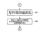
- the target temperature of the cooling water is set based on the minimum value of (SA7 in FIG. 7). Subsequently, the target flow rate of the coolant, the target flow rate of the coolant, and the target rotation speed of the fan 23 are set so as to satisfy the set target temperature and required cooling amount of the coolant (SA8).
- the pump 19, the pump 28, and the fan 23 are driven based on the set cooling conditions (SA9).
- SA9 set cooling conditions
- various target values are transmitted to a drive control unit (not shown) that drives the pump 19, the pump 28, and the fan 23, respectively, and each drive control unit performs drive control according to the target value.
- the rotation speed of the electric motor that drives the pump 19 is driven and controlled based on the target flow rate of the coolant
- the rotation speed of the electric motor that drives the pump 28 is driven and controlled based on the target flow rate of the coolant
- the fan The fan 23 is driven and controlled based on the target rotation speed of the fan 23 .
- the pumps 19 and 28 and the fan 23 are driven and controlled based on the target values, so that the cooling liquid is sent from the pump 19 to the heat exchanger 17 at a discharge amount corresponding to the required cooling amount.
- the cooling liquid is cooled to a temperature based on the required cooling amount, and the cooling liquid at a temperature and flow rate that satisfies the required cooling amount is delivered to the liquid immersion bath 3 .
- the required cooling amount is calculated based on the parameters related to the operating state of the electronic device 30, and the cooling conditions are set in consideration of the required cooling amount. Since the operating state of the electronic device 30 has a correlation with the amount of heat generated by the electronic device 30, it is possible to calculate the required cooling amount according to the amount of heat generated by using parameters related to the operating state of the electronic device 30. . This makes it possible to set appropriate cooling conditions according to the amount of heat generated by the electronic device. Furthermore, according to this embodiment, a plurality of cooling modes are provided, and the cooling conditions are set based on the selected cooling mode and the required cooling amount, so it is possible to perform appropriate cooling according to the desired mode. becomes.
- the cooling conditions are set so as to achieve the maximum cooling effect derived from the outside air conditions.
- the cooling conditions are set so as to achieve a maximum or near maximum cooling effect, and to maintain the performance of the electronic device 30 at or above the desired performance.
- the target temperature of the cooling water is set within a range that does not exceed a predetermined temperature determined based on the maximum allowable temperature of the electronic components that make up the electronic device 30. Further, the cooling conditions are set so as to satisfy the target temperature and required cooling amount of the cooling water and to minimize the power consumption. As a result, all the electronic devices 30 can be kept below the maximum allowable temperature while suppressing power consumption.
- FIG. 8 is a functional block diagram showing an example of the functions of the system control device 40a according to this embodiment.
- the system control device 40a includes a correction section 54 that corrects the required cooling amount calculated by the calculation section 52.
- FIG. 8 is a functional block diagram showing an example of the functions of the system control device 40a according to this embodiment.
- the system control device 40a includes a correction section 54 that corrects the required cooling amount calculated by the calculation section 52.
- the correction unit 54 corrects the required cooling amount based on the discrepancy between the distribution of the parameters indicating the operating state of the plurality of electronic devices 30 in the liquid immersion tank 3 and the cooling efficiency distribution in the liquid immersion tank 3 .
- the “distribution of parameters indicating operating states” is, for example, power consumption distribution.
- FIG. 9A a substrate 11 on which a plurality of electronic devices 30 are mounted is arranged along the X-axis inside the liquid immersion tank 3 .
- FIG. 9A shows a two-dimensional diagram, but as described above, the substrates 11 are also arranged in the depth direction (Y-axis).
- the cooling effect is not uniform within the liquid immersion tank 3 as shown in FIG. 9B.
- variations may occur. That is, there may be a position where it is easy to cool and a position where it is difficult to cool.
- the cooling effect is highest at the central portion of the liquid immersion bath 3 and decreases toward the sides.
- the variation in the cooling effect shown in FIG. 9B is an example, and the degree of variation is affected by various factors such as the structure and shape of the liquid immersion bath 3 .
- FIGS. 9C and 9D are diagrams showing examples of variation (distribution) of power consumption of the substrate 11 with respect to position.
- the power consumption distribution shown in FIG. 9(c) shows almost the same tendency as the cooling effect distribution shown in FIG. 9(b), with little deviation.
- the power consumption distribution shown in FIG. 9D the power consumption of the substrate 11 arranged in the center is low, and the power consumption of the substrate 11 increases toward the sides. This power consumption distribution has a tendency opposite to that of the cooling efficiency distribution shown in FIG.
- the required cooling amount is corrected based on the deviation (deviation amount) between the cooling effect and the power consumption at each position of the liquid immersion bath 3 .
- the correction unit 54 has a preset cooling effect distribution. Then, the power consumption distribution of the entire electronic device 30 is calculated from the power consumption obtained from the power consumption meter, and the calculated power consumption distribution and the cooling effect distribution are compared to determine the relative deviation of the distribution. calculate.
- the comparison of the distributions may be performed using known statistical methods such as a method of making the respective distributions dimensionless based on the average value, standard deviation, etc. and then comparing them, a method of normalizing them and then comparing them.
- the amount of deviation is calculated by, for example, calculating the difference between the dimensionless value of the power consumption and the dimensionless value of the cooling efficiency at that position for each substrate 11, and accumulating the calculated differences.
- One example is a method of calculating the deviation amount of the distribution of .
- the correction unit 54 calculates a correction amount based on the amount of deviation of the distribution calculated by the above method and the average value of the power consumption of the electronic device 30 as a whole. For example, the correction unit 54 calculates the correction amount by substituting each calculated value into the correction amount calculation formula including the deviation amount of the distribution and the average value of the power consumption of the entire electronic device 30 as variables. .
- the correction amount is an arithmetic expression in which the correction amount increases as the shift amount increases.
- the calculation formula is such that the higher the average value of the power consumption, the smaller the correction amount.
- the correction unit 54 corrects the required cooling amount calculated by the calculation unit 52 using the calculated correction amount. For example, the required cooling amount is corrected by adding the correction amount to the required cooling amount. When the correction amount is obtained as a correction coefficient, the required cooling amount may be corrected by multiplying the required cooling amount by the correction coefficient.
- the corrected required cooling amount is output to the cooling condition setting unit 53, and the cooling condition is set using this corrected required cooling amount.
- the system control device 40a controls the distribution of parameters (for example, the distribution of power consumption) indicating the operating state with respect to the positions of the plurality of electronic devices 30 in the liquid immersion tank 3 and the liquid A correction unit 54 is provided for correcting the required cooling amount based on the deviation from the cooling efficiency distribution with respect to the position in the immersion bath 3 .
- parameters for example, the distribution of power consumption
- the liquid A correction unit 54 is provided for correcting the required cooling amount based on the deviation from the cooling efficiency distribution with respect to the position in the immersion bath 3 .
- the distribution of CPU load factors estimated from the execution status of calculation jobs given to each board 11 may be used as the distribution of parameters indicating the operating state. Similar to the power consumption, the CPU load factor also has a correlation with the amount of heat generated by the electronic device 30 . Therefore, instead of power consumption, a distribution based on the CPU load factor may be calculated, the calculated CPU load factor distribution and the cooling effect distribution may be compared, and the amount of deviation between them may be calculated. The correction amount is calculated using the deviation amount of the distribution and the average value of the CPU load factor in the same manner as described above.
- FIG. 10 is a diagram showing an example of temporal changes in calculation jobs given to each substrate 11 (first substrate to fifth substrate). If the calculation load of the calculation job is high, the CPU load factor will increase, and if the calculation load of the calculation job is low, the CPU load factor will decrease. For example, at time T1, the CPU load on the second board and the third board is larger than the CPU load on the first board, the fourth board and the fifth board. Therefore, at time T1, it is presumed that the amount of heat generated by the second and third substrates is greater than that of the other substrates.
- the amount of heat generated by the electronic device 30 changes more slowly than changes in the CPU load factor. Therefore, the average value of the CPU load factor in a predetermined period may be calculated for each substrate 11, and the average value distribution may be used to compare with the cooling effect distribution.
- the cooling condition is set in consideration of the operating state of the electronic device 30 in the future. becomes possible.
- FIG. 11 in addition to the first embodiment, a flow rate adjustment unit 34 is provided for each nozzle 32, and as shown in FIG. It is different in that it has In the following description, the configuration different from that of the first embodiment will be mainly described, and common items will be denoted by the same reference numerals, and description thereof will be omitted.
- the liquid immersion cooling system 1 is provided with a flow rate adjusting section 34 for each nozzle 32 .
- the flow rate adjuster 34 adjusts the flow rate of the coolant Lq discharged from the nozzle 32 .
- An example of the flow control unit 34 is a flow control valve.
- the flow rate adjusting unit 34 is controlled by the system control device 40b.
- FIG. 12 is a functional block diagram showing an example of the functions of the system control device 40b according to this embodiment. As shown in FIG. 12, the system control device 40b includes a nozzle flow control section 55. As shown in FIG. 12, the system control device 40b includes a nozzle flow control section 55. As shown in FIG. 12, the system control device 40b includes a nozzle flow control section 55. As shown in FIG. 12, the system control device 40b includes a nozzle flow control section 55.
- the nozzle flow control unit 55 controls the flow control unit 34 so that the cooling efficiency becomes uniform when there is variation in the cooling efficiency distribution.
- the nozzle flow rate control unit 55 increases the valve opening degree of the flow rate adjustment unit 34 corresponding to a position where the cooling efficiency is lower than a predetermined value (for example, an average value), thereby increasing the discharge amount of the cooling liquid.
- a predetermined value for example, an average value
- the nozzle flow rate control unit 55 may control the valve opening degree of the flow rate adjustment unit 34 according to the difference between the power consumption distribution and the cooling effect distribution in the liquid immersion tank 3. good.
- the method of calculating the distribution difference is as described in the second embodiment. By comparing the power consumption distribution and the cooling effect distribution in this manner, the difference in the distribution at each position of the substrate 11 is calculated, and the valve opening degree of the flow rate adjusting unit 34 is adjusted according to this difference. For example, for a position where the cooling effect is relatively low but the power consumption is relatively large, the amount of cooling liquid discharged is increased by opening the valve opening of the flow rate adjusting unit 34, thereby reducing the power consumption and the cooling rate. It is possible to reduce the difference from the effect.
- the valve opening degree of the flow rate adjusting unit 34 is throttled to reduce the discharge amount of the cooling liquid, thereby reducing the power consumption.
- the difference between volume and cooling effect can be small.
- the CPU load factor may be used instead of the power consumption.
- the system control device 40 sets the target flow rate of the coolant, the target flow rate of the coolant, and the target temperature of the coolant.
- the system controller 40 controlled both the coolant circulation unit 5 and the cooling unit 7 .
- the present embodiment differs in that it includes a cooling unit control section 60 that controls the cooling unit 7 and a cooling liquid circulation unit control section 70 that controls the cooling liquid circulation unit 5 .
- the configuration different from that of the first embodiment will be mainly described, and common items will be denoted by the same reference numerals, and description thereof will be omitted.
- FIG. 13 is a functional block diagram showing an example of the functions of the cooling unit controller 60.
- the cooling unit 7 includes, for example, a cooling unit controller 60 .
- the coolant circulation unit 5 includes a coolant circulation unit controller 70 .
- the cooling unit control section 60 and the coolant circulation unit control section 70 may be configured to be able to communicate with each other. As a result, for example, the cooling unit control section 60 can acquire information about the flow rate of the cooling liquid from the cooling liquid circulation unit control section 70 .
- Examples of the information about the flow rate of the cooling liquid include the target flow rate of the cooling liquid, the detection value of the flow rate sensor of the cooling liquid, and the rotation speed or frequency of the pump 19 that controls the flow rate of the cooling liquid.
- the target flow rate of the coolant is used as the information regarding the flow rate of the coolant will be described below as an example.
- the flow rate of the coolant may be estimated from the number of revolutions or frequency of the pump 19 .
- the flow rate of the coolant may be controlled to be constant.
- the cooling unit control section 60 includes, for example, a mode selection section 51, a calculation section 52, and a cooling condition setting section 53a.
- the cooling condition setting unit 53 a sets the target temperature and the target flow rate of the cooling water based on the cooling mode selected by the mode selection unit 51 and the required cooling amount calculated by the calculation unit 52 .
- the cooling condition setting unit 53a sets the target temperature and the target flow rate of the cooling water based on the required cooling amount and the target flow rate of the cooling liquid.
- These settings can be set, for example, by using the value obtained from the cooling liquid circulation unit control section 70 as the flow rate of the cooling liquid in the various calculation methods described in the first embodiment.
- the control value target flow rate, etc.
- the registered control value is used to control the target temperature of the cooling water. And it is good also as setting a target flow volume. In such a case, communication with the coolant circulation unit control section 70 is also unnecessary.
- the cooling condition setting unit 53a sets the target temperature of the cooling water to the lowest temperature derived from the outside air condition.
- the cooling condition setting unit 53a may set the target rotation speed of the fan 23 to the maximum rotation speed.
- the cooling condition setting unit 53 may also set the target flow rate of cooling water to the maximum flow rate.
- the cooling condition setting unit 53a sets the target temperature of the cooling water based on a predetermined temperature determined based on the heat resistance characteristics of the electronic components forming the electronic device 30. do. Furthermore, the cooling condition setting unit 53a uses the target flow rate of the cooling liquid acquired from the cooling liquid circulation unit control unit 70 or the target flow rate of the cooling liquid registered in advance to set the target temperature of the cooling water and the required cooling amount. A target flow rate of the cooling water and a target rotation speed of the fan 23 are set. At this time, the target flow rate of the cooling water and the target rotation speed of the fan 23 are preferably set so that the power of the pump 28 and the fan 23 is minimized. Optimization of the target flow rate of the cooling medium and the target rotation speed of the fan 23 can be realized by using a known optimization method.
- the cooling condition setting unit 53a may sequentially set various target values so as to satisfy the required cooling amount based on a predetermined order set in advance.
- the predetermined order is the order of elements with the highest power reduction effect. For example, if the power reduction effect is higher in the order of the power of the fan 23 and the power of the pump 28, the target values may be set in this order.
- the cooling conditions set by the cooling condition setting unit 53a in this way (for example, the target rotation speed of the pump 28 and the target rotation speed of the fan 23) are set by the drive control unit ( (not shown), and these are driven according to the target value.
- the required cooling amount is calculated based on the parameters related to the operating state of the electronic device 30, and the cooling conditions are set in consideration of the required cooling amount. Since the operating state of the electronic device 30 has a correlation with the amount of heat generated by the electronic device 30, it is possible to calculate the required cooling amount according to the amount of heat generated by using parameters related to the operating state of the electronic device 30. . This makes it possible to set the appropriate cooling conditions for the cooling unit 7 according to the amount of heat generated by the electronic device 30 . Furthermore, according to this embodiment, a plurality of cooling modes are provided, and the cooling conditions are set based on the selected cooling mode and the required cooling amount, so the cooling unit 7 can be appropriately controlled according to the mode. It becomes possible.
- the cooling conditions of the cooling unit 7 are set so as to achieve the maximum cooling effect derived from the outside air conditions.
- the cooling unit 7 can exhibit the maximum or nearly the maximum cooling capacity.
- the target temperature of the cooling water is set within a range that does not exceed a predetermined temperature determined based on the maximum allowable temperature of the electronic components that make up the electronic device 30. Furthermore, the cooling conditions of the cooling unit 7 are set so that the target temperature and required cooling amount of the cooling water are satisfied and the power consumption of the cooling unit 7 is minimized. As a result, all the electronic devices 30 can be kept below the maximum allowable temperature while suppressing the power consumption of the cooling unit 7 .
- the cooling unit control section 60 may further include the correction section 54 . Since the details of the correction unit 54 have been described in the second embodiment, description thereof will be omitted here.
- cooling unit control section 60 and the cooling liquid circulation unit control section 70 may be implemented by the same processing circuit, or may be implemented by different processing circuits (in other words, different computers).
- the system control device 40 sets the target flow rate of the coolant, the target flow rate of the coolant, and the target temperature of the coolant.
- the system controller 40 controlled both the coolant circulation unit 5 and the cooling unit 7 .
- the present embodiment differs in that a cooling unit control section 60a that controls the cooling unit 7 and a cooling liquid circulation unit control section 70a that controls the cooling liquid circulation unit 5 are provided.
- the configuration different from that of the first embodiment will be mainly described, and common items will be denoted by the same reference numerals, and description thereof will be omitted.
- FIG. 14 is a functional block diagram showing an example of the functions of the coolant circulation unit control section 70a.
- the cooling unit 7 includes, for example, a cooling unit controller 60a.
- the coolant circulation unit 5 includes a coolant circulation unit controller 70a.
- the cooling unit control section 60a and the coolant circulation unit control section 70a may be configured to be able to communicate with each other. As a result, for example, the coolant circulation unit controller 70a can acquire information about the temperature and flow rate of the coolant from the cooling unit controller 60a.
- the coolant circulation unit control section 70a includes, for example, a mode selection section 51, a calculation section 52, and a cooling condition setting section 53b.
- the cooling condition setting unit 53b sets the target flow rate of the coolant based on the cooling mode selected by the mode selection unit 51 and the required cooling amount calculated by the calculation unit 52.
- the cooling condition setting unit 53b sets the required cooling amount calculated by the calculation unit 52, the inlet temperature of the coolant flowing into the heat exchanger 17, and the heat exchanger 17 A target flow rate of the coolant is set based on the coolant outlet temperature delivered from the .
- the cooling amount is represented by the following formula.
- Cooling amount (Cooling liquid inlet temperature - Cooling liquid outlet temperature) x Cooling liquid flow rate (2)
- the cooling condition setting unit 53b calculates the coolant flow rate by substituting the required cooling amount for the cooling amount and the temperature sensor detection value for the cooling liquid inlet temperature and the cooling liquid outlet temperature in the above equation (2). and set the calculated coolant flow rate as the target flow rate.
- the cooling condition setting unit 53b sets the target flow rate of the coolant to the maximum flow rate.
- the cooling liquid circulation unit 5 is controlled so that the maximum cooling capacity can be exhibited by setting the target flow rate of the cooling liquid to the maximum flow rate.
- the cooling condition setting unit 53b sets the target temperature of the coolant based on a predetermined temperature determined based on the heat resistance characteristics of the electronic components constituting the electronic device 30. and set the target coolant flow rate to the minimum coolant flow rate that satisfies the required cooling rate.
- the "predetermined temperature” is, for example, the lowest allowable maximum temperature among the allowable maximum temperatures of the electronic components immersed in the liquid immersion bath 3, or the allowable maximum temperature with a predetermined margin. temperature.
- the cooling condition setting unit 53b sets the required cooling amount for the cooling amount, the detection value of the temperature sensor for the cooling liquid inlet temperature, and the "coolant target temperature" for the cooling liquid outlet temperature in the above equation (2).
- the coolant flow rate for obtaining the required cooling amount is calculated, and the calculated coolant flow rate is set as the target flow rate.
- the cooling conditions set by the cooling condition setting unit 53b in this manner are transmitted to a drive control unit (not shown) that drives the pump 19 of the coolant circulation unit 5, and the pump 19 is controlled according to the cooling conditions. done.
- the required cooling amount is calculated based on the parameters related to the operating state of the electronic device 30, and the cooling conditions are set in consideration of the required cooling amount. Since the operating state of the electronic device 30 has a correlation with the amount of heat generated by the electronic device 30, it is possible to calculate the required cooling amount according to the amount of heat generated by using parameters related to the operating state of the electronic device 30. . As a result, it is possible to set appropriate cooling conditions for the coolant circulation unit 5 according to the amount of heat generated by the electronic device 30 . Furthermore, according to this embodiment, a plurality of cooling modes are provided, and the cooling conditions are set based on the selected cooling mode and the required cooling amount, so the cooling liquid circulation unit 5 is appropriately controlled according to the mode. becomes possible.
- the target flow rate of the coolant is set to the maximum flow rate. This makes it possible to maximize the cooling capacity of the coolant circulation unit 5 .
- the supply temperature of the cooling liquid is set based on a predetermined temperature determined based on the heat resistance characteristics of the electronic components constituting the electronic device 30, and the required cooling amount is set.
- Set the target coolant flow rate to the minimum coolant flow rate that satisfies As a result, all the electronic devices 30 can be kept below the maximum allowable temperature while suppressing the power consumption of the coolant circulation unit 5 .
- the coolant circulation unit control section 70a may further include the correction section 54. Since the details of the correction unit 54 have been described in the second embodiment, description thereof will be omitted here.
- cooling unit control section 60a and the coolant circulation unit control section 70a may be realized by the same processing circuit, or may be realized by different processing circuits (in other words, different computers).
- the coolant circulation system 6 has the cooling unit 7 in the fifth embodiment described above, the cooling unit 7 may be omitted.
- the heat exchanger 17 in the coolant circulation unit 5 is an air-cooled heat exchanger that exchanges heat with the outside air.
- the control by the coolant circulation unit control section 70a is as described above.
- the temperature sensor detects the outlet temperature of the cooling liquid sent from the heat exchanger 17, and the detected value is used to set the target flow rate of the cooling liquid.
- the present invention is not limited to this.
- the cooling unit control section 60a and the coolant circulation unit control section 70a are configured to be able to communicate with each other, the target temperature and the target flow rate of the cooling water are acquired from the cooling unit control section 60a, and the acquired target temperature and flow rate are obtained. information may be used to estimate the coolant outlet temperature. By estimating the coolant outlet temperature in this way, it is possible to omit a temperature sensor for measuring the coolant outlet temperature.
- the pump 19 controls the flow rate of the cooling liquid and the pump 28 controls the flow rate of the cooling water.
- the discharge rate of the pump 19 may be constant, in other words, the pump 19 may be a fixed-speed pump, and a flow rate adjusting section for adjusting the flow rate may be provided in the coolant circulation path.
- the discharge rate of the pump 28 may be constant, in other words, the pump 28 may be a fixed-speed pump, and a flow rate adjusting section for adjusting the flow rate may be provided in the cooling water circulation path.
- An example of the flow control unit is a flow control valve.
- cooling water was used as an example of the cooling medium that exchanges heat with the cooling liquid, but the cooling medium is not limited to this example. It is also possible to use liquids other than water as the cooling medium.
- the cooling unit 7 has been described by exemplifying a mode in which the cooling water is directly cooled by the outside air taken in by the fan 23, but the invention is not limited to this example.
- the cooling unit 7 may be configured to cool cooling water using a coolant such as water, such as a chiller as a cooling unit.
- the cooling condition setting unit may set parameters for controlling the cooling unit. More specifically, the cooling condition setting unit sets, instead of the number of revolutions of the fan 23, the amount of circulation of the coolant for cooling the cooling water.
- the mode selection unit 51 can be omitted.
- the cooling conditions are set according to the control when the cooling mode is set to the normal mode.
- the temperature and flow rate of the coolant are controlled according to the operating state of the electronic device 30, but instead of this, for example, an operation job given to the electronic device 30 can be controlled according to the cooling state.
- an operation job given to the electronic device 30 can be controlled according to the cooling state.
- FIG. 9(b) when the cooling efficiency varies depending on the position, the substrate 11 (server) arranged at the position with the high cooling efficiency is assigned the operation job with the high operation load.
- an operation job with a low operation load may be assigned to the board 11 (server) arranged at a position with low cooling efficiency.
- the cooling liquid circulation unit and its control method and program described in each of the embodiments described above are grasped, for example, as follows.
- a cooling liquid circulation unit (5) is a cooling liquid circulation unit that circulates cooling liquid in a liquid immersion tank (3) that cools a plurality of electronic devices (30) by immersing them in cooling liquid.
- a flow rate adjustment unit (19) provided in the cooling liquid circulation path for circulating the cooling liquid to the liquid immersion tank, and a flow rate adjusting section (19) provided in the cooling liquid circulation path and exchanging heat between the cooling liquid and the cooling medium.
- a calculation unit (52) for calculating a required cooling amount based on parameters relating to the operating states of a plurality of electronic devices; and a cooling condition setting unit (53b) for setting.
- the required cooling amount is calculated based on the parameters related to the operating state of the electronic device, and the cooling conditions are set in consideration of the required cooling amount. Since the operating state of the electronic device has a correlation with the amount of heat generated by the electronic device, it is possible to calculate the required cooling amount according to the amount of heat generated by using parameters related to the operating state of the electronic device. As a result, it is possible to set appropriate cooling conditions for the coolant circulation unit according to the amount of heat generated by the electronic device. Furthermore, since a plurality of cooling modes are provided and cooling conditions are set based on the selected cooling mode and required cooling amount, it is possible to perform appropriate cooling according to the desired mode.
- the plurality of cooling modes includes a performance priority mode that prioritizes the performance of the electronic device, and the cooling condition setting unit selects the performance priority mode.
- the target flow rate of the coolant may be set to the maximum flow rate.
- the plurality of cooling modes includes an energy-saving priority mode that prioritizes power usage efficiency, and the cooling condition setting unit sets the energy-saving priority mode when the energy-saving priority mode is selected. , based on the predetermined temperature determined based on the heat resistance characteristics of the electronic components that make up the electronic equipment, set the cooling liquid delivery temperature to the liquid immersion tank, and set the cooling liquid to the minimum flow rate that satisfies the required cooling amount. It is also possible to set the target flow rate of
- the cooling liquid circulation unit control unit controls the distribution of parameters indicating the operating state with respect to the arrangement of the plurality of electronic devices in the liquid immersion tank and the cooling in the liquid immersion tank.
- a correction unit that corrects the required cooling amount based on the deviation from the efficiency distribution, and the cooling condition setting unit adjusts parameters related to the flow rate of the coolant based on the selected cooling mode and the corrected required cooling amount.
- a target value may be set.
- the parameters that indicate the operating status of an electronic device have a correlation with the amount of heat generated by the electronic device. Therefore, by comparing the distribution of such parameters and the cooling effect distribution and correcting the required cooling amount based on the difference between them, the variation in the heat generation amount and the cooling efficiency of the electronic equipment in the liquid immersion bath can be reduced. It is possible to set appropriate cooling conditions in consideration of the above.
- the correcting unit is configured based on the difference between the power consumption distribution for the arrangement of the plurality of electronic devices in the liquid immersion tank and the cooling efficiency distribution in the liquid immersion tank. may be used to correct the required cooling amount.
- the amount of power consumption has a correlation with the amount of heat generated by electronic devices. Therefore, by comparing the power consumption distribution and the cooling effect distribution and correcting the necessary cooling amount based on the difference between them, the variation in the amount of heat generation and the variation in the cooling efficiency of the electronic equipment in the liquid immersion bath can be corrected. It becomes possible to set appropriate cooling conditions in consideration.
- the correction unit determines the amount of deviation between the power consumption distribution for the arrangement of the plurality of electronic devices in the liquid immersion tank and the cooling efficiency distribution in the liquid immersion tank, and The required cooling amount may be corrected based on the average value of the power consumption of a plurality of electronic devices.
- the correcting unit is configured based on the difference between the calculation load distribution with respect to the arrangement of the plurality of electronic devices in the liquid immersion tank and the cooling efficiency distribution in the liquid immersion tank. , the required cooling amount may be corrected.
- the computational load of electronic equipment has a correlation with the amount of heat generated by the electronic equipment. Therefore, by comparing the calculation load distribution and the cooling effect distribution and correcting the necessary cooling amount based on the difference between them, the variation in the heat generation amount of the electronic equipment in the liquid immersion bath and the variation in the cooling efficiency are considered. Therefore, it is possible to set appropriate cooling conditions.
- the correcting unit determines the amount of deviation between the calculation load distribution for the arrangement of the plurality of electronic devices in the liquid immersion bath and the cooling efficiency distribution in the liquid immersion bath, and the number of The required cooling amount may be corrected based on the average calculation load of the electronic device.
- calculation load examples include a calculation load factor, a CPU load factor, and the like.
- the calculation load distribution may be estimated based on parameters relating to the execution status of calculation jobs given to a plurality of electronic devices.
- a control method for a cooling liquid circulation unit (5) is a control method for a cooling liquid circulation unit that circulates cooling liquid in a liquid immersion tank in which a plurality of electronic devices are immersed in cooling liquid to be cooled.
- the cooling liquid circulation unit includes a flow rate adjustment unit provided in the cooling liquid circulation path for circulating the cooling liquid in the liquid immersion bath, and a cooling liquid circulation path provided in the cooling liquid circulation path to separate the cooling liquid and the cooling medium.
- a heat exchanger that exchanges heat
- the control method includes a step of selecting one of a plurality of cooling modes and a step of calculating a required cooling amount based on parameters relating to the operating states of the plurality of electronic devices. and setting a target value of a parameter relating to the flow rate of the coolant based on the selected cooling mode and the required cooling amount.
- a program according to one aspect of the present disclosure is a program for causing a computer to function as the cooling liquid circulation unit control section described above.
- a liquid immersion cooling system (1) includes the cooling liquid circulation unit (5) described above and a liquid immersion tank (3).
Landscapes
- Engineering & Computer Science (AREA)
- Microelectronics & Electronic Packaging (AREA)
- Physics & Mathematics (AREA)
- Thermal Sciences (AREA)
- Theoretical Computer Science (AREA)
- Human Computer Interaction (AREA)
- General Engineering & Computer Science (AREA)
- General Physics & Mathematics (AREA)
- Cooling Or The Like Of Electrical Apparatus (AREA)
- Cooling Or The Like Of Semiconductors Or Solid State Devices (AREA)
Abstract
電子機器の発熱量を考慮して冷却条件を設定することを目的とする。 冷却液循環ユニットは、複数の電子機器を冷却液に浸漬させて冷却する液浸槽に対して冷却液を循環させる。冷却液循環ユニットは、液浸槽に対して冷却液を循環させる冷却液循環路に設けられた流量調整部と、冷却液循環路に設けられるとともに、冷却液と冷却媒体とを熱交換する熱交換器と、冷却液循環ユニット制御部とを備える。冷却液循環ユニット制御部(70a)は、複数の冷却モードのうちのいずれか一つを選択するモード選択部(51)と、複数の電子機器の稼働状態に関するパラメータに基づいて必要冷却量を算出する算出部(52)と、選択された冷却モードと必要冷却量とに基づいて、冷却液の流量に関するパラメータの目標値を設定する冷却条件設定部(53b)とを具備する。
Description
本開示は、液浸槽に対して冷却液を循環させる冷却液循環ユニット及びその制御方法並びにプログラムに関するものである。
特許文献1には、データセンターにおいてサーバやストレージ等の電子機器を冷却液中に浸漬して冷却する液浸冷却システムが開示されている。具体的には、特許文献1には、冷却槽によって電子機器を冷却して加温された冷却液を熱交換器において冷却し、冷却後の冷却液を冷却槽に戻すことにより、冷却液を循環させる液浸冷却システムが開示されている。
例えば、電子機器の発熱量は、一定ではなく変化する。このため、発熱量に応じて冷却条件を変えることが望まれる。
本開示は、このような事情に鑑みてなされたものであって、電子機器の発熱量を考慮して冷却条件を設定することのできる冷却液循環ユニット及びその制御方法並びにプログラムを提供することを目的とする。
本開示の第1態様は、複数の電子機器を冷却液に浸漬させて冷却する液浸槽に対して冷却液を循環させる冷却液循環ユニットであって、前記液浸槽に対して冷却液を循環させる冷却液循環路に設けられた流量調整部と、前記冷却液循環路に設けられるとともに、冷却液と冷却媒体とを熱交換する熱交換器と、冷却液循環ユニット制御部とを備え、冷却液循環ユニット制御部は、複数の冷却モードのうちのいずれか一つを選択するモード選択部と、複数の前記電子機器の稼働状態に関するパラメータに基づいて必要冷却量を算出する算出部と、選択された前記冷却モードと前記必要冷却量とに基づいて、前記冷却液の流量に関するパラメータの目標値を設定する冷却条件設定部とを具備する冷却液循環ユニットである。
本開示の第2態様は、複数の電子機器を冷却液に浸漬させて冷却する液浸槽に対して冷却液を循環させる冷却液循環ユニットの制御方法であって、前記冷却液循環ユニットは、前記液浸槽に対して冷却液を循環させる冷却液循環路に設けられた流量調整部と、前記冷却液循環路に設けられるとともに、冷却液と冷却媒体とを熱交換する熱交換器とを備え、前記制御方法は、複数の冷却モードのうちのいずれか一つを選択する工程と、複数の前記電子機器の稼働状態に関するパラメータに基づいて必要冷却量を算出する工程と、選択された前記冷却モードと前記必要冷却量とに基づいて、前記冷却液の流量に関するパラメータの目標値を設定する工程とを有する冷却液循環ユニットの制御方法である。
本開示の第3態様は、コンピュータを上記冷却液循環ユニット制御部として機能させるためのプログラムである。
本開示の第4態様は、上記冷却液循環ユニットと、前記液浸槽とを備える液浸冷却システムである。
電子機器の発熱量を考慮して冷却条件を設定することができる。
以下に、本開示に係る複数の実施形態について、図面を参照して説明する。
〔第1実施形態〕
以下、本開示の第1実施形態について説明する。
図1は、本実施形態に係る液浸冷却システム1の概略構成を示した概略図である。液浸冷却システム1は、液浸槽(容器)3と、冷却液循環システム6とを備えている。
〔第1実施形態〕
以下、本開示の第1実施形態について説明する。
図1は、本実施形態に係る液浸冷却システム1の概略構成を示した概略図である。液浸冷却システム1は、液浸槽(容器)3と、冷却液循環システム6とを備えている。
液浸槽3は、内部に冷却液Lqが貯留される有底の容器とされている。液浸槽3は、有底とされて四方に側壁部3bを有する本体3aと、本体3aの上面に設けられた開閉蓋3cとを有している。
冷却液Lqは、電気絶縁性を有する液体が用いられ、例えばシリコーン系オイル等が用いられる。冷却液Lqは、液浸槽3の本体3a内に設置された基板11の全体が浸かる程度の高さまで満たされる。
冷却液Lqは、電気絶縁性を有する液体が用いられ、例えばシリコーン系オイル等が用いられる。冷却液Lqは、液浸槽3の本体3a内に設置された基板11の全体が浸かる程度の高さまで満たされる。
開閉蓋3cは、側壁部3bの上端を中心に回動して開閉する。開閉蓋3cは、液浸槽3の本体3a内に基板11を設置したり取り外したりする場合や、液浸槽3内のメンテナンス時に開状態とされる。開閉蓋3cは、通常使用時(基板11の冷却時)には閉状態とされる。
液浸槽3の本体3a内には、例えば、各基板11に実装される形で複数の電子機器が浸漬させている。電子機器の一例として、電子計算機(サーバ)やストレージ等があげられる。図1では、一例として、複数の基板11が液浸槽3内に設置されている場合を示している。各基板11は、例えばサーバを構成する基板とされ、長手方向を鉛直方向に向けた状態で所定の間隔を空けて配列されている。基板の配列や電子機器の搭載態様についてはこれに限られない。
冷却液循環システム6は、液浸槽3に対して冷却液を循環させる。具体的には、冷却液循環システム6は、液浸槽3において基板11に実装された電子機器を冷やすことにより加熱された冷却液を熱交換器17によって冷却し、冷却後の冷却液を液浸槽3に戻すことにより、冷却液を循環させる。
冷却液循環システム6は、冷却液循環ユニット5と、冷却ユニット7と、後述するシステム制御装置40(図4参照)とを備えている。冷却液循環ユニット5は、冷却液循環路と、ポンプ19と、熱交換器17とを備えている。冷却液循環路は、例えば、返液管15、冷却液吐出管21、及び送液管13を備えている。冷却液循環路には、ポンプ19と熱交換器17とが設けられている。
冷却液循環ユニット5は、例えば、送液管13及び返液管15を介して液浸槽3と接続されている。送液管13の下流端13aは、液浸槽3の側壁部3bに接続されている。送液管13の上流端13bは、冷却液循環ユニット5の内部に設置された熱交換器17に接続されている。返液管15の上流端15aは、液浸槽3の側壁部3bに接続されている。返液管15の下流端15bは、冷却液循環ユニット5の内部に設置された冷却液を循環させるためのポンプ(第1流量調整部)19に接続されている。
熱交換器17は、冷却ユニット7から供給された冷却水と、ポンプ19から冷却液吐出管21を介して供給された冷却液とを熱交換する。冷却液は、熱交換器17で冷却水と熱交換することによって冷却される。
ポンプ19は、例えば電動モータによって駆動され、後述するシステム制御装置(図4参照)によって吐出量が制御される。
ポンプ19は、例えば電動モータによって駆動され、後述するシステム制御装置(図4参照)によって吐出量が制御される。
冷却液循環ユニット5には、熱交換器17に流入する冷却液温度と、熱交換器17から送出される冷却液出口温度とをそれぞれ検出するための温度センサ(図示略)が設けられている。冷却液循環ユニット5には、冷却液流量を検出するための流量センサが設けられていてもよい。
冷却ユニット7は、冷却水(冷却媒体)が循環する冷却水循環路を備えている。冷却水循環路は、例えば、冷却水供給管25と冷却水返送管26とを備えている。冷却水循環路には、冷却水を循環させるためのポンプ(第2流量調整部)28が設けられている。ポンプ28は、例えば電動モータによって駆動され、後述するシステム制御装置(図4参照)によって吐出量が制御される。
冷却ユニット7は、ファン(冷却部)23を備えており、ファン23によって冷却用の外気が取り込まれる。ファン23の発停及び回転数は、後述するシステム制御装置(図4参照)によって制御される。冷却水循環路を循環する冷却水は、ファン23によって取り込まれた外気と熱交換することによって、冷却される。
冷却ユニット7において、外気との間で熱交換されることにより冷却された冷却水は、冷却水供給管25を介して熱交換器17に供給される。熱交換器17にて熱交換した後の冷却水は、冷却水返送管26を介して冷却ユニット7に戻される。
冷却ユニット7には、熱交換器17に流入する冷却水の温度である冷却水入口温度と、熱交換器17から返送される冷却水の温度である冷却水出口温度とをそれぞれ検出するための温度センサ(図示略)が設けられている。冷却ユニット7には、冷却水流量を検出するための流量センサが設けられていてもよい。
図2には、液浸槽3の本体3a内に設置された複数の基板11が示されている。図2に示した一例では、基板11は、基板11の幅方向(図2においてx方向)に4枚設けられ、奥行き方向(図2においてy方向)に12枚設けられている。ただし、基板11の設置数はこれに限定されるものではない。
各基板11には、サーバを構成するためのCPU、電源ユニット、メモリ、ハードディスク又はSSD(Solid State Drive)等のストレージ、及び通信ユニットなどの複数の電子機器30が実装されている。これら電子機器30は、サーバの動作中に発熱し、冷却液Lqによって冷却される。
各基板11には、サーバを構成するためのCPU、電源ユニット、メモリ、ハードディスク又はSSD(Solid State Drive)等のストレージ、及び通信ユニットなどの複数の電子機器30が実装されている。これら電子機器30は、サーバの動作中に発熱し、冷却液Lqによって冷却される。
各基板11の上端には、把持部11aが固定されている。把持部11aは基板11の上端から上方に突出するように設けられ、棒状体を曲げて形成した門型形状とされている。把持部11aを作業者が掴むことによって、基板11の設置及び取り外しが行われる。
各基板11の上端に対して直交するように有孔壁11bが設けられている。有孔壁11bは、電子機器30が設けられた表面側に立設している。有孔壁11bは、多数の孔が形成された例えばパンチングメタルとされている。有孔壁11bの孔の数や径を適宜設定することによって、基板11の表面上を流れる冷却液の流量が調整される。
各基板11の両側のそれぞれには、例えば、上下方向に延在する側板11cが設けられている。側板11cは、電子機器30が設けられた表面側に立設するように設けられ、かつ基板11の長手方向(上下方向,z方向)の全体にわたって連続して設けられている。側板11cによって基板11の両側を囲むことによって、基板11の表面上を流れる冷却液Lqの流れをガイドするようになっている。
各基板11の下方には、複数のノズル32が設けられている。ノズル32は、電子機器30が設けられた基板11の表面上を基板11の一端(下端)から他端(上端)に向かって冷却液が流動するように冷却液を吐出する。
ノズル32は、例えば、各基板11に対して複数設けられている。具体的には、ノズル32は、基板11の一端(下端)から他端(上端)に向かう冷却液の流れ方向(z方向)に交差する幅方向(x方向)に並列に複数設けられている。これにより、基板11の一端(下端)から他端(上端)に向かう冷却液Lqの流れが並列に複数形成される。ノズル32の数は、1つの基板11に対して2以上であればよく、冷却液Lqの流れ及び冷却状態に応じて適宜設定される。
ノズル32は、奥行き方向(図2のy方向)にも同様に、各基板11に対応して設けられている。したがって、y方向に並べられた各基板11の間にもノズル32が設けられている。
図3に示すように、各ノズル32の上流側は、分岐管36を介して供給主管38に接続されている。供給主管38の上流側は、送液管13の下流端13a(図1参照)に接続されている。したがって、送液管13から導かれた冷却液Lqは、供給主管38を介して各分岐管36へ分配されるようになっている。
このような構成を備える液浸冷却システム1は、一例として、以下の通り動作する。
ポンプ19が後述するシステム制御装置40によって制御されることによって、冷却液Lqが流動し、熱交換器17へと導かれる。熱交換器17では、冷却ユニット7で冷却された冷却水と熱交換して冷却液Lqが冷却される。熱交換器17を出た冷却液Lqは、送液管13を通り液浸槽3へと導かれる。液浸槽3へと導かれた冷却液Lqは、図3に示したように送液管13から供給主管38を通り各分岐管36へ分配される。各分岐管36へ導かれた冷却液Lqは、ノズル32へと導かれて吐出される。
ポンプ19が後述するシステム制御装置40によって制御されることによって、冷却液Lqが流動し、熱交換器17へと導かれる。熱交換器17では、冷却ユニット7で冷却された冷却水と熱交換して冷却液Lqが冷却される。熱交換器17を出た冷却液Lqは、送液管13を通り液浸槽3へと導かれる。液浸槽3へと導かれた冷却液Lqは、図3に示したように送液管13から供給主管38を通り各分岐管36へ分配される。各分岐管36へ導かれた冷却液Lqは、ノズル32へと導かれて吐出される。
各ノズル32から吐出した冷却液Lqは、基板11の下端へと導かれて、側板11cによってガイドされながら電子機器30が設けられた基板11の表面上を通り、基板11の上端へと向かう。このときに、電子機器30から発熱した熱量が冷却液Lqへと奪われて電子機器30が冷却される。
電子機器30を冷却して加温された冷却液Lqは、基板11の上端に設けられた有孔壁11bの孔を通過して基板11の上方から排出される。基板11の上方から排出された冷却液Lqは、液浸槽3の本体3a内に貯留された冷却液Lqと合流して混合される。
本体3a内に貯留された冷却液Lqの一部は、返液管15から抜き出されてポンプ19を介して熱交換器17へと導かれて冷却され、再び液浸槽3へと導かれる。
本体3a内に貯留された冷却液Lqの一部は、返液管15から抜き出されてポンプ19を介して熱交換器17へと導かれて冷却され、再び液浸槽3へと導かれる。
次に、本実施形態に係るシステム制御装置40について説明する。図4は、本実施形態に係るシステム制御装置40のハードウェア構成の一例を示した図である。図4に示すように、システム制御装置40は、いわゆるコンピュータであり、例えば、CPU(Central Processing Unit)41、メインメモリ42、記憶部43、及び通信部45等を備えている。システム制御装置40は、例えば、入力部46及び表示部47を備えていてもよい。この場合、入力部46及び表示部47は、通信回線を介して通信部45と接続され、例えば、遠隔から入力等を実現できる、いわゆる遠隔操作が可能な構成とされていてもよい。
上記各部構成は、直接的にまたはバスを介して間接的に相互に接続されており、互いに連携して各種処理を実行する。
上記各部構成は、直接的にまたはバスを介して間接的に相互に接続されており、互いに連携して各種処理を実行する。
CPU41は、例えば、バスを介して接続された記憶部43に格納されたOS(Operating System)により冷却液循環システム6全体の制御を行うとともに、記憶部43に格納された各種プログラムを実行することにより各種処理を実行する。
メインメモリ42は、例えば、キャッシュメモリ、RAM(Random Access Memory)等の書き込み可能なメモリで構成され、CPU41の実行プログラムの読み出し、実行プログラムによる処理データの書き込み等を行う作業領域として利用される。
記憶部43は、非一時的な記録媒体(non-transitory computer readable storage medium)である。一例として、ROM(Read Only Memory)、HDD(Hard Disk Drive)、フラッシュメモリ等が挙げられる。記憶部43は、例えば、Windows(登録商標)、iOS(登録商標)、Android(登録商標)等の冷却液循環システム6全体の制御を行うためのOSを格納する。記憶部43は、例えば、BIOS(Basic Input/Output System)を格納していてもよい。記憶部43は、周辺機器類をハードウェア操作するための各種デバイスドライバ、各種アプリケーションソフトウェア、及び各種データやファイル等を格納していてもよい。記憶部43には、各種処理を実現するためのプログラムや、各種処理を実現するために必要とされる各種データが格納されていてもよい。
通信部45は、ネットワークに接続して他の装置と通信を行い、情報の送受信を行うためのインターフェースとして機能する。例えば、通信部45は、有線又は無線により他の装置と通信を行う。無線通信として、Bluetooth(登録商標)、Wi-Fi、専用の通信プロトコルを用いた通信等が挙げられる。有線通信の一例として、有線LAN(Local Area Network)等が挙げられる。
入力部46は、例えば、キーボード、マウス、タッチパッド等、ユーザが冷却液循環システム6に対して指示を与えるためのユーザインタフェースである。
表示部47は、例えば、液晶ディスプレイ、有機EL(Electroluminescence)ディスプレイ等である。表示部47は、タッチパネルが重畳されたタッチパネルディスプレイでもよい。
図5は、システム制御装置40が備える機能の一例を示した機能ブロック図である。図5に示されるように、システム制御装置40は、例えば、モード選択部51、算出部52、及び冷却条件設定部53を備えている。
これら機能の全て又は一部は、例えば、処理回路(processing circuitry)によって実現される。例えば、以下に示す機能を実現するための一連の処理は、一例として、プログラム(例えば、システム制御プログラム)の形式で記憶部43に記憶されており、このプログラムをCPU41がメインメモリ42に読み出して、情報の加工・演算処理を実行することにより、各種機能が実現される。
プログラムは、記憶部43に予めインストールされている形態や、他のコンピュータ読み取り可能な記憶媒体に記憶された状態で提供される形態、有線又は無線による通信手段を介して配信される形態等が適用されてもよい。コンピュータ読み取り可能な記憶媒体とは、磁気ディスク、光磁気ディスク、CD-ROM、DVD-ROM、半導体メモリ等である。
モード選択部51は、複数のモードを備えている。複数のモードは、電子機器30の性能を優先させる性能優先モードを有していてもよい。複数のモードは、電力使用効率を優先させる省エネ優先モードを有していてもよい。複数のモードは、通常モードを有していてもよい。
モード選択部51は、複数のモードのうちのいずれか一つを選択する。例えば、モード選択部51は、所定のスケジュールに従っていずれかのモードを選択する。例えば、モード選択部51は、サーバの運用スケジュール等に基づいて選択すべき冷却モードが予めスケジューリングされており、このスケジュールに応じて冷却モードを選択することとしてもよい。モード選択部51は、入力部46からの入力指示に基づいて、指定された冷却モードを選択してもよい。
算出部52は、複数の電子機器30の稼働状態に関するパラメータに基づいて必要冷却量を算出する。ここで、複数の電子機器30の稼働状態に関するパラメータの一例として、例えば、消費電力、消費電力量、CPU負荷率、又は発熱温度、若しくはこれらの2つ以上の組み合わせが挙げられる。
電子機器30の発熱量は、稼働状態に応じて変化する。このため、電子機器30の稼働状態に関するパラメータを用いることにより、電子機器30の発熱量を推定でき、これにより、必要な冷却量を推定することが可能となる。
CPU負荷率を取得する場合には、電子機器30とシステム制御装置40との間で通信が生じるため、電子機器30の負担が大きくなる。これに対し、電子機器30との直接の通信を必要としないパラメータ、例えば、消費電力又は消費電力量を稼働状態に関するパラメータとして用いることにより、電子機器30に処理負担を負わせることなく、必要冷却量を算出することが可能となる。CPU負荷率の代わりに、電子機器30に与えられるジョブに基づいてCPU負荷率を推定する手法を採用してもよい。
CPU負荷率を取得する場合には、電子機器30とシステム制御装置40との間で通信が生じるため、電子機器30の負担が大きくなる。これに対し、電子機器30との直接の通信を必要としないパラメータ、例えば、消費電力又は消費電力量を稼働状態に関するパラメータとして用いることにより、電子機器30に処理負担を負わせることなく、必要冷却量を算出することが可能となる。CPU負荷率の代わりに、電子機器30に与えられるジョブに基づいてCPU負荷率を推定する手法を採用してもよい。
算出部52は、例えば、電子機器30の稼働状態に関するパラメータを変数として含む必要冷却量の演算式を有している。そして、この演算式に、その時々のパラメータの検出値を入力することにより、必要冷却量を算出する。
例えば、電子機器30の稼働状態に関するパラメータとして、消費電力量を用いる場合、必要冷却量は、消費電力量に所定の比例係数を乗じることにより算出されてもよい。演算式は、一例であり、この限りではない。例えば、事前試験やシミュレーションなどによって、電子機器30の稼働状態に関するパラメータと必要冷却量との関係を求めておけばよい。必要冷却量は、例えば、電子機器30が所定の演算能力を発揮できる温度に基づいて決定され、求められる演算能力に応じて適宜設定される。
例えば、電子機器30の稼働状態に関するパラメータとして、消費電力量を用いる場合、必要冷却量は、消費電力量に所定の比例係数を乗じることにより算出されてもよい。演算式は、一例であり、この限りではない。例えば、事前試験やシミュレーションなどによって、電子機器30の稼働状態に関するパラメータと必要冷却量との関係を求めておけばよい。必要冷却量は、例えば、電子機器30が所定の演算能力を発揮できる温度に基づいて決定され、求められる演算能力に応じて適宜設定される。
液浸冷却システム1は、電子機器30の稼働状態に関するパラメータを検出するための構成を備えている。
例えば、液浸冷却システム1は、電子機器30の消費電力を検出する消費電力計(図示略)と、消費電力計から出力される信号をシステム制御装置40に伝送する通信部(図示略)とを有する。消費電力計として、例えば、コンセントに差し込んで使用するワットモニタ等の公知のセンサを使用することが可能である。
例えば、液浸冷却システム1は、電子機器30の消費電力を検出する消費電力計(図示略)と、消費電力計から出力される信号をシステム制御装置40に伝送する通信部(図示略)とを有する。消費電力計として、例えば、コンセントに差し込んで使用するワットモニタ等の公知のセンサを使用することが可能である。
液浸冷却システム1は、電子機器30の温度を計測する温度センサ(図示略)と、温度センサから出力される信号をシステム制御装置40に伝送する通信部(図示略)とを有していてもよい。温度センサは、例えば、電子機器30の中でも発熱量の大きい部品に取り付けられ、通信部を通じて検出値をシステム制御装置40に伝送する。
上記電子機器30の稼働状態に関するパラメータは、基板11毎(例えば、サーバ毎)、または、複数の基板11で構成される基板群毎(サーバ群毎)に取得してもよい。すなわち、液浸槽3に浸漬されている電子機器30全体としてのパラメータ値が得られれば、その取得の方法については限られない。
冷却条件設定部53は、例えば、算出部52によって算出された必要冷却量に基づいて、冷却液の流量に関するパラメータ及び冷却水の温度に関するパラメータ又は/及び冷却水の流量に関するパラメータを設定する。
例えば、冷却条件設定部53は、通常モードが選択されていた場合、必要冷却量に基づいて、冷却液の目標流量、冷却水の目標温度、及び冷却水の目標流量を設定する。ここで、冷却水の目標温度とは、熱交換器17(図1参照)に対して供給される冷却水の目標温度である。
一例として、冷却条件設定部53は、必要冷却量と、冷却液の流量、冷却水の温度、及び冷却水の流量とが関連付けられた1又は複数のマップ情報を有しており、このマップ情報を用いることにより、必要冷却量から冷却液の目標流量、冷却水の目標温度、及び冷却水の目標流量を得る。
他の例として、冷却条件設定部53は、必要冷却量から冷却液の目標流量、冷却水の目標温度、及び冷却水の目標流量を得るための演算式を有しており、この演算式を用いて必要冷却量から冷却液の目標流量、冷却水の目標温度、及び冷却水の目標流量を算出してもよい。
ここで、冷却水入口温度の限界最小温度は、外部条件に基づいて決定される。例えば、冷却水入口温度の限界温度は、外気湿球温度に所定温度(例えば、5℃)加算した値となる。この限界最小温度は、ファン23を最大回転数で駆動した場合に、冷却水を冷やすことのできる限界温度である。したがって、例えば、冷却水の目標温度が外気条件に基づいて決定される限界最小温度以下であった場合には、冷却水の目標温度を限界最小温度に設定し、その上で、必要冷却量が得られるように、他のパラメータ、すなわち、冷却液の目標流量や冷却水の目標流量を設定することとしてもよい。
ここで、冷却水入口温度の限界最小温度は、外部条件に基づいて決定される。例えば、冷却水入口温度の限界温度は、外気湿球温度に所定温度(例えば、5℃)加算した値となる。この限界最小温度は、ファン23を最大回転数で駆動した場合に、冷却水を冷やすことのできる限界温度である。したがって、例えば、冷却水の目標温度が外気条件に基づいて決定される限界最小温度以下であった場合には、冷却水の目標温度を限界最小温度に設定し、その上で、必要冷却量が得られるように、他のパラメータ、すなわち、冷却液の目標流量や冷却水の目標流量を設定することとしてもよい。
ファン23の目標回転数は、例えば、冷却水の目標温度(熱交換器17の冷却水入口温度)と、冷却水出口温度と、冷却水の目標流量とを所定の演算式に用いることにより算出される。ここで、冷却ユニット7における冷却量は、例えば、以下の(1)式で表される。したがって、以下の演算式において必要冷却量が得られるようにファン23の目標回転数が設定される。外気条件(例えば、外気湿球温度)を更にパラメータとして含む演算式に基づいて、ファン23の回転数を決定することとしてもよい。
冷却量
=(熱交換器の冷却水出口温度-熱交換器の冷却水入口温度)×冷却水流量 (1)
=(熱交換器の冷却水出口温度-熱交換器の冷却水入口温度)×冷却水流量 (1)
冷却条件設定部53は、例えば、冷却モードとして性能優先モードが選択されている場合には、外気条件から導出される最低温度に冷却水の目標温度を設定する。冷却条件設定部53は、冷却液の目標流量を最大流量に設定するとともに、ファン23の目標回転数を最大回転数に設定することとしてもよい。さらに、冷却条件設定部53は、冷却水の目標流量についても最大流量に設定することとしてもよい。
これにより、性能優先モードが選択されている場合には、外気条件から導出される最大の冷却効果または最大に近い効果が得られるように、冷却液循環システム6が制御されることとなる。
これにより、性能優先モードが選択されている場合には、外気条件から導出される最大の冷却効果または最大に近い効果が得られるように、冷却液循環システム6が制御されることとなる。
冷却条件設定部53は、冷却モードとして省エネ優先モードが選択されている場合には、電子機器30を構成する電子部品の耐熱特性に基づいて決定される所定の温度に基づいて、冷却水の目標温度を設定するとともに、設定した冷却水の目標温度及び必要冷却量を満たすように、冷却液の目標流量、冷却水の目標流量、及びファン23の目標回転数を消費電力が最も小さくなるように最適化してもよい。
ここで、「所定の温度」とは、例えば、液浸槽3に浸漬されている電子部品の許容最大温度のうち、最も低い許容最大温度又はその許容最大温度に所定の裕度を持たせた温度である。
ここで、「所定の温度」とは、例えば、液浸槽3に浸漬されている電子部品の許容最大温度のうち、最も低い許容最大温度又はその許容最大温度に所定の裕度を持たせた温度である。
上記冷却液の目標流量、冷却水の目標流量、及びファン23の目標回転数の最適化については、公知の最適化手法を用いることで実現可能である。
冷却条件設定部53は、予め設定されている所定の順序に基づいて、必要冷却量を満たすように、各種目標値を順次設定することとしてもよい。例えば、所定の順序は、動力削減効果が最も高い要素順とされている。例えば、ファン23の動力、ポンプ28の動力、ポンプ19の動力の順に動力削減効果が高い場合、この順番で目標値を設定すればよい。
冷却条件設定部53は、予め設定されている所定の順序に基づいて、必要冷却量を満たすように、各種目標値を順次設定することとしてもよい。例えば、所定の順序は、動力削減効果が最も高い要素順とされている。例えば、ファン23の動力、ポンプ28の動力、ポンプ19の動力の順に動力削減効果が高い場合、この順番で目標値を設定すればよい。
このようにして冷却条件設定部53によって冷却条件が設定されると、設定された冷却条件に基づいて冷却液循環ユニット5のポンプ19、冷却ユニット7のポンプ28及びファン23が制御される。具体的には、冷却液の目標流量に応じた周波数で、ポンプ19の電動モータが制御されることにより、ポンプ19の吐出量が目標流量に制御される。冷却水の目標流量に応じた周波数で、ポンプ28の電動モータが制御されることにより、ポンプ28の吐出量が目標流量に制御される。ファン23の目標回転数に基づいて、ファン23が制御される。
次に、本実施形態に係るシステム制御装置40によって実現される制御方法について図6及び図7を参照して説明する。図6及び図7は、本実施形態に係る冷却液循環システム6の制御方法の手順の一例を示したフローチャートである。以下に示す一連の処理は、例えば、処理回路によって実現される。具体的には、CPU41が記憶部43に記憶されているプログラムをメインメモリ42に読み出して、情報の加工・演算処理を実行することにより実現される。
以下、電子機器30の稼働状態に関するパラメータとして、電子機器30の消費電力量を用いる場合を例示して説明する。各種バリエーションについては、上述した通りであり、本開示に係る制御方法は、以下に説明する各種処理に限定されない。
以下の一連の処理は、例えば、所定の時間間隔で繰り返し実行される。
以下の一連の処理は、例えば、所定の時間間隔で繰り返し実行される。
まず、システム制御装置40は、消費電力計(図示略)によって検出された検出値に基づいて、液浸槽3に浸漬されている電子機器30全体の消費電力量を算出する(SA1)。
続いて、システム制御装置40は、消費電力量を所定の演算式に代入することにより、必要冷却量を算出する(SA2)。
続いて、現在選択されている冷却モードが通常モードであるか否かを判定する(SA3)。この結果、通常モードである場合には(SA3:YES)、必要冷却量に基づいて冷却条件を設定する(SA4)。これにより、必要冷却量に基づいて、冷却液の目標流量、冷却水の目標温度、及び冷却水の目標流量が設定される。冷却水の目標温度、冷却水の熱交換器出口温度、及び冷却水の目標流量に基づいて、ファンの目標回転数が設定される。
冷却モードとして通常モードが選択されていない場合(SA3:NO)、冷却モードとして性能優先モードが選択されているか否かを判定する(SA5)。性能優先モードが選択されている場合には(SA5:YES)、冷却液の目標流量を最大流量に設定し、ファンの目標回転数を最大回転数に設定し、冷却水の目標流量を最大流量に設定する(SA6)。
一方、冷却モードとして性能優先モードが選択されていない場合(SA5:NO)には、冷却モードとして省エネモードが選択されていると判定し、電子機器30を構成する多数の電子部品の最大許容温度の最小値に基づいて冷却水の目標温度を設定する(図7のSA7)。続いて、設定した冷却水の目標温度及び必要冷却量を満たすように、冷却液の目標流量、冷却水の目標流量、及びファン23の目標回転数を設定する(SA8)。
続いて、設定された冷却条件に基づいて、ポンプ19、ポンプ28、ファン23を駆動する(SA9)。例えば、各種目標値は、ポンプ19、ポンプ28、及びファン23をそれぞれ駆動する駆動制御部(図示略)に送信され、各駆動制御部によって目標値に応じた駆動制御が行われる。
これにより、冷却液の目標流量に基づいてポンプ19を駆動する電動モータの回転数が駆動制御され、冷却水の目標流量に基づいてポンプ28を駆動する電動モータの回転数が駆動制御され、ファン23の目標回転数に基づいてファン23が駆動制御される。
このようにして、ポンプ19、28、及びファン23が目標値に基づいて駆動制御されることにより、ポンプ19から必要冷却量に応じた吐出量で冷却液が熱交換器17に送られ、熱交換器17において、必要冷却量に基づく温度まで冷却液が冷却されることにより、必要冷却量を満足する温度及び流量の冷却液が液浸槽3に送出されることとなる。
以上説明した本実施形態の作用効果は以下の通りである。
本実施形態によれば、電子機器30の稼働状態に関するパラメータに基づいて必要冷却量を算出し、必要冷却量を考慮して冷却条件を設定する。電子機器30の稼働状態は、電子機器30の発熱量と相関関係を有するため、電子機器30の稼働状態に関するパラメータを用いることで、発熱量に応じた必要冷却量を算出することが可能となる。これにより、電子機器の発熱量に応じた適切な冷却条件を設定することが可能となる。
さらに、本実施形態によれば、複数の冷却モードを設け、選択されている冷却モード及び必要冷却量に基づいて冷却条件を設定するので、所望のモードに応じた適切な冷却を行うことが可能となる。
本実施形態によれば、電子機器30の稼働状態に関するパラメータに基づいて必要冷却量を算出し、必要冷却量を考慮して冷却条件を設定する。電子機器30の稼働状態は、電子機器30の発熱量と相関関係を有するため、電子機器30の稼働状態に関するパラメータを用いることで、発熱量に応じた必要冷却量を算出することが可能となる。これにより、電子機器の発熱量に応じた適切な冷却条件を設定することが可能となる。
さらに、本実施形態によれば、複数の冷却モードを設け、選択されている冷却モード及び必要冷却量に基づいて冷却条件を設定するので、所望のモードに応じた適切な冷却を行うことが可能となる。
例えば、冷却モードとして性能優先モードが選択されている場合には、外気条件から導出される最大の冷却効果を実現するように冷却条件が設定される。これにより、最大限またはそれに近い冷却効果を実現することができ、電子機器30の性能を所望の性能以上に保つことが可能となる。
冷却モードとして省エネ優先モードが選択されている場合には、電子機器30を構成する電子部品の最大許容温度に基づいて決定された所定の温度を超えない範囲で、冷却水の目標温度が設定され、更に、この冷却水の目標温度及び必要冷却量を満たすように、かつ、消費電力が最も小さくなるように冷却条件が設定される。これにより、消費電力を抑制しながら、全ての電子機器30を最大許容温度以下に保つことができる。
〔第2実施形態〕
次に、本開示の第2実施形態について説明する。本実施形態は、第1実施形態に加えて、補正部を設けた点が相違する。したがって、以下の説明では、第1実施形態と相違する構成について主に説明し、共通する事項は同一符号を付してその説明を省略する。
次に、本開示の第2実施形態について説明する。本実施形態は、第1実施形態に加えて、補正部を設けた点が相違する。したがって、以下の説明では、第1実施形態と相違する構成について主に説明し、共通する事項は同一符号を付してその説明を省略する。
図8は、本実施形態に係るシステム制御装置40aが備える機能の一例を示した機能ブロック図である。図8に示すように、システム制御装置40aは、算出部52によって算出された必要冷却量を補正する補正部54を備えている。
補正部54は、液浸槽3内における複数の電子機器30の配置に対する稼働状態を示すパラメータの分布と液浸槽3内における冷却効率分布とのずれに基づいて、必要冷却量を補正する。「稼働状態を示すパラメータの分布」は、例えば、消費電力量分布である。
例えば、図9(a)に示すように、液浸槽3内には、複数の電子機器30が実装された基板11がX軸に沿って配置されている。説明の便宜上、図9(a)では、二次元の図を示しているが、基板11は、奥行方向(Y軸)にも配列されていることは上述した通りである。
液浸槽3の下方に設けられたノズル32(図3参照)から均一に冷却液を供給したとしても、図9(b)に示すように、冷却効果は液浸槽3内において均一ではなく、ばらつきが生ずる場合がある。すなわち、冷えやすい位置と、冷えにくい位置が存在する場合がある。図9(b)に示した例では、冷却効果は液浸槽3の中央部分が最も高く、側部に近づくほど低下している。図9(b)に示した冷却効果のばらつきは、一例であり、ばらつき具合は、液浸槽3の構造や形状等、様々な要因に応じて影響を受ける。
液浸槽3内に配置された複数の基板11(電子機器30)の消費電力量もその稼働状態に応じてばらつきがある。例えば、図9(c)、(d)は、位置に対する基板11の消費電力量のばらつき(分布)の例をそれぞれ示した図である。例えば、図9(c)に示した消費電力量分布は、図9(b)に示した冷却効果分布とほぼ同じ傾向を示しており、ずれが少ない。これに対し、図9(d)に示した消費電力量分布は、中央に配置された基板11の消費電力量は低く、側部に行くほど基板11の消費電力量は高くなっている。この消費電力量分布は、図9(b)に示した冷却効率分布と逆の傾向にあり、分布のずれが大きいことがわかる。
本実施形態では、このような液浸槽3の各位置における冷却効果と消費電力量とのずれ(ずれ量)に基づいて必要冷却量を補正する。
例えば、補正部54は、予め設定された冷却効果分布を有している。そして、消費電力計から取得した消費電力量から電子機器30全体の消費電力量分布を算出し、算出した消費電力量分布と冷却効果分布とを比較することにより、分布の相対的なずれ量を算出する。分布の比較は、例えば、それぞれの分布を平均値や標準偏差等に基づいて無次元化した上で比較する方法、正規化した上で比較する方法等、公知の統計的手法を用いればよい。
例えば、補正部54は、予め設定された冷却効果分布を有している。そして、消費電力計から取得した消費電力量から電子機器30全体の消費電力量分布を算出し、算出した消費電力量分布と冷却効果分布とを比較することにより、分布の相対的なずれ量を算出する。分布の比較は、例えば、それぞれの分布を平均値や標準偏差等に基づいて無次元化した上で比較する方法、正規化した上で比較する方法等、公知の統計的手法を用いればよい。
ずれ量の算出は、例えば、基板11毎に、その位置における消費電力量を無次元化した値と冷却効率を無次元化した値との差分を算出し、算出した差分を累計することによって全体の分布のずれ量を演算する方法が一例として挙げられる。
そして、補正部54は、上述の手法によって算出した分布のずれ量と、電子機器30全体の消費電力量の平均値とに基づいて、補正量を算出する。例えば、補正部54は、分布のずれ量と電子機器30全体の消費電力量の平均値とを変数として含む補正量演算式に対して、それぞれの演算値を代入することにより補正量を算出する。ここで、補正量は、ずれ量が大きいほど補正量が大きい演算式とされている。消費電力量の平均値が高いほど、補正量が小さくなるような演算式とされている。
補正部54は、補正量を算出すると、算出した補正量を用いて、算出部52によって算出された必要冷却量を補正する。例えば、補正量を必要冷却量に加算することによって必要冷却量を補正する。補正量が補正係数として得られる場合には、必要冷却量に補正係数を乗じることにより、必要冷却量を補正することとしてもよい。
このようにして必要冷却量が補正されると、補正後の必要冷却量は冷却条件設定部53に出力され、この補正後の必要冷却量を用いて冷却条件が設定される。
上述したように、本実施形態によれば、システム制御装置40aは、液浸槽3内における複数の電子機器30の位置に対する稼働状態を示すパラメータの分布(例えば、消費電力量の分布)と液浸槽3内における位置に対する冷却効率分布とのずれに基づいて、必要冷却量を補正する補正部54を備える。これにより、液浸槽3内における電子機器30の発熱量のばらつきと冷却効率のばらつきとを考慮した適切な冷却条件を設定することが可能となる。
稼働状態を示すパラメータの分布として、各基板11(各サーバ)に与えられる計算ジョブの実行状況から推測されるCPU負荷率の分布を用いてもよい。上記消費電力量と同様に、CPU負荷率も電子機器30の発熱量と相関関係を有する。したがって、消費電力量に代えて、CPU負荷率に基づく分布を算出し、算出したCPU負荷率の分布と冷却効果分布とを比較して、それらのずれ量を算出することとしてもよい。補正量は、上述と同様に、分布のずれ量と、CPU負荷率の平均値とを用いて算出する。
図10は、各基板11(第1基板~第5基板)に与えられる計算ジョブの時間的変化の一例を示した図である。計算ジョブの演算負荷が高ければCPU負荷率は増加し、計算ジョブの演算負荷が低ければCPU負荷率は低下する。例えば、時刻T1に着目すると、第1基板、第4基板、及び第5基板のCPU負荷に比べて第2基板、第3基板のCPU負荷は大きい。このため、時刻T1については、第2基板と第3基板の発熱量が他の基板よりも大きくなることが推測される。
CPU負荷率の変化に比べて電子機器30の発熱量は緩やかに変化する。したがって、基板11毎に所定期間におけるCPU負荷率の平均値を算出し、平均値の分布を用いて冷却効果分布と比較することとしてもよい。
このように、計算ジョブからCPU負荷率を推定し、推定したCPU負荷率の分布を用いて補正量を算出することにより、将来における電子機器30の稼働状態を加味して冷却条件の設定をすることが可能となる。
〔第3実施形態〕
次に、本開示の第3実施形態について説明する。実施形態では、図11に示すように、第1実施形態に加えて、各ノズル32に対して流量調整部34を設けるとともに、図12に示すように、システム制御装置40bがノズル流量制御部55を備える点で相違する。
以下の説明では、第1実施形態と相違する構成について主に説明し、共通する事項は同一符号を付してその説明を省略する。
次に、本開示の第3実施形態について説明する。実施形態では、図11に示すように、第1実施形態に加えて、各ノズル32に対して流量調整部34を設けるとともに、図12に示すように、システム制御装置40bがノズル流量制御部55を備える点で相違する。
以下の説明では、第1実施形態と相違する構成について主に説明し、共通する事項は同一符号を付してその説明を省略する。
図11に示すように、本実施形態に係る液浸冷却システム1は、各ノズル32に流量調整部34が設けられている。流量調整部34は、ノズル32から吐出される冷却液Lqの流量を調整する。流量調整部34の一例として、流量調整弁が挙げられる。流量調整部34は、システム制御装置40bによって制御される。
図12は、本実施形態に係るシステム制御装置40bが備える機能の一例を示した機能ブロック図である。図12に示すように、システム制御装置40bは、ノズル流量制御部55を備えている。
ノズル流量制御部55は、例えば、図9(b)に示したように、冷却効率分布にばらつきがある場合に、冷却効率が均一となるように流量調整部34を制御する。例えば、ノズル流量制御部55は、冷却効率が所定値(例えば、平均値)よりも低い位置に対応する流量調整部34の弁開度を増加させ、冷却液の吐出量を増加させる一方で、冷却効果が所定値よりも高い位置に対応する流量調整部34の弁開度を絞ることで、冷却液の吐出量を減少させる。これにより、液浸槽3における冷却効率のばらつきを低減させることができる。
上記制御に代えて、例えば、ノズル流量制御部55は、液浸槽3内における電力消費量分布と冷却効果分布との差分に応じて、流量調整部34の弁開度を制御することとしてもよい。
分布の差分の算出方法については、第2実施形態で述べた通りである。このように、電力消費量分布と冷却効果分布とを比較することにより、各基板11の位置における分布の差分を算出し、この差分に応じて流量調整部34の弁開度を調整する。例えば、冷却効果が比較的低いのに電力消費量が比較的大きい位置については、流量調整部34の弁開度を開くことにより、冷却液の吐出量を増加させることで、電力消費量と冷却効果との差分を小さくすることができる。同様に、例えば、冷却効果が比較的高いのに電力消費量が比較的小さい位置については、流量調整部34の弁開度を絞ることにより、冷却液の吐出量を減少させることで、電力消費量と冷却効果との差分を小さくすることができる。
このように、各ノズルに対応して設けられた流量調整部34を制御することにより、位置に応じた細やかな冷却制御を行うことが可能となる。
上記電力消費量に代えてCPU負荷率を用いてもよいことは、第2実施形態で述べた通りである。
分布の差分の算出方法については、第2実施形態で述べた通りである。このように、電力消費量分布と冷却効果分布とを比較することにより、各基板11の位置における分布の差分を算出し、この差分に応じて流量調整部34の弁開度を調整する。例えば、冷却効果が比較的低いのに電力消費量が比較的大きい位置については、流量調整部34の弁開度を開くことにより、冷却液の吐出量を増加させることで、電力消費量と冷却効果との差分を小さくすることができる。同様に、例えば、冷却効果が比較的高いのに電力消費量が比較的小さい位置については、流量調整部34の弁開度を絞ることにより、冷却液の吐出量を減少させることで、電力消費量と冷却効果との差分を小さくすることができる。
このように、各ノズルに対応して設けられた流量調整部34を制御することにより、位置に応じた細やかな冷却制御を行うことが可能となる。
上記電力消費量に代えてCPU負荷率を用いてもよいことは、第2実施形態で述べた通りである。
〔第4実施形態〕
次に、本開示の第4実施形態について説明する。第1実施形態では、システム制御装置40が、冷却液の目標流量、冷却水の目標流量、及び冷却水の目標温度を設定していた。換言すると、システム制御装置40は、冷却液循環ユニット5および冷却ユニット7の両方を制御していた。これに対し、本実施形態では、冷却ユニット7を制御する冷却ユニット制御部60と、冷却液循環ユニット5を制御する冷却液循環ユニット制御部70とをそれぞれ有する点で相違する。
以下の説明では、第1実施形態と相違する構成について主に説明し、共通する事項は同一符号を付してその説明を省略する。
次に、本開示の第4実施形態について説明する。第1実施形態では、システム制御装置40が、冷却液の目標流量、冷却水の目標流量、及び冷却水の目標温度を設定していた。換言すると、システム制御装置40は、冷却液循環ユニット5および冷却ユニット7の両方を制御していた。これに対し、本実施形態では、冷却ユニット7を制御する冷却ユニット制御部60と、冷却液循環ユニット5を制御する冷却液循環ユニット制御部70とをそれぞれ有する点で相違する。
以下の説明では、第1実施形態と相違する構成について主に説明し、共通する事項は同一符号を付してその説明を省略する。
図13は、冷却ユニット制御部60が備える機能の一例を示した機能ブロック図である。本実施形態において、冷却ユニット7は、例えば、冷却ユニット制御部60を備えている。冷却液循環ユニット5は、冷却液循環ユニット制御部70を備えている。
冷却ユニット制御部60と冷却液循環ユニット制御部70とは、相互通信が可能な構成とされていてもよい。これにより、例えば、冷却ユニット制御部60は、冷却液循環ユニット制御部70から冷却液の流量に関する情報を取得することが可能となる。
冷却ユニット制御部60と冷却液循環ユニット制御部70とは、相互通信が可能な構成とされていてもよい。これにより、例えば、冷却ユニット制御部60は、冷却液循環ユニット制御部70から冷却液の流量に関する情報を取得することが可能となる。
冷却液の流量に関する情報の一例として、冷却液の目標流量、冷却液の流量センサの検出値、または冷却液の流量を制御するポンプ19の回転数または周波数等が挙げられる。以下、冷却液の流量に関する情報として、冷却液の目標流量を用いる場合を例示して説明する。冷却液の流量に関する情報としてポンプ19の回転数または周波数を用いる場合には、ポンプ19の回転数または周波数から冷却液の流量を推定すればよい。
本実施形態において、冷却液の流量は一定に制御されていてもよい。
本実施形態において、冷却液の流量は一定に制御されていてもよい。
冷却ユニット制御部60は、例えば、モード選択部51、算出部52、冷却条件設定部53aを備えている。冷却条件設定部53aは、モード選択部51によって選択された冷却モードと、算出部52によって算出された必要冷却量とに基づいて、冷却水の目標温度及び冷却水の目標流量を設定する。
例えば、冷却条件設定部53aは、冷却モードとして通常モードが選択されていた場合、必要冷却量と冷却液の目標流量とに基づいて、冷却水の目標温度及び冷却水の目標流量を設定する。これらの設定は、例えば、第1実施形態で説明した各種演算手法において、冷却液の流量に冷却液循環ユニット制御部70から取得した値を用いることによって設定可能である。冷却液循環ユニット制御部70がポンプ19を一定吐出量で制御するような場合には、予めその制御値(目標流量等)を登録しておき、登録した制御値を用いて冷却水の目標温度及び目標流量を設定することとしてもよい。このような場合、冷却液循環ユニット制御部70との通信も不要となる。
冷却条件設定部53aは、例えば、冷却モードとして性能優先モードが選択されている場合には、外気条件から導出される最低温度に冷却水の目標温度を設定する。例えば、冷却条件設定部53aは、ファン23の目標回転数を最大回転数に設定することとしてもよい。さらに、冷却条件設定部53は、冷却水の目標流量についても最大流量に設定することとしてもよい。
これにより、性能優先モードが選択されている場合には、外気条件から導出される最大の冷却効果または最大に近い効果が得られるように、冷却ユニット7が制御されることとなる。
これにより、性能優先モードが選択されている場合には、外気条件から導出される最大の冷却効果または最大に近い効果が得られるように、冷却ユニット7が制御されることとなる。
冷却条件設定部53aは、省エネ優先モードが選択されている場合には、電子機器30を構成する電子部品の耐熱特性に基づいて決定される所定の温度に基づいて、冷却水の目標温度を設定する。さらに、冷却条件設定部53aは、冷却液循環ユニット制御部70から取得した冷却液の目標流量又はあらかじめ登録されている冷却液の目標流量を用いて、設定した冷却水の目標温度及び必要冷却量を満たす冷却水の目標流量及びファン23の目標回転数を設定する。このとき、冷却水の目標流量及びファン23の目標回転数は、ポンプ28及びファン23の動力が最も小さくなるように設定するとよい。上記冷却媒体の目標流量及びファン23の目標回転数の最適化については、公知の最適化手法を用いることで実現可能である。
冷却条件設定部53aは、予め設定されている所定の順序に基づいて、必要冷却量を満たすように、各種目標値を順次設定することとしてもよい。例えば、所定の順序は、動力削減効果が最も高い要素順とされている。例えば、ファン23の動力、ポンプ28の動力の順に動力削減効果が高い場合、この順番で目標値を設定すればよい。
このようにして冷却条件設定部53aによって設定された冷却条件(例えば、ポンプ28の目標回転数及びファン23の目標回転数)は、冷却ユニット7のポンプ28及びファン23を駆動する駆動制御部(図示略)に送信され、目標値に応じてこれらが駆動されることとなる。
このように、本実施形態によれば、電子機器30の稼働状態に関するパラメータに基づいて必要冷却量を算出し、必要冷却量を考慮して冷却条件を設定する。電子機器30の稼働状態は、電子機器30の発熱量と相関関係を有するため、電子機器30の稼働状態に関するパラメータを用いることで、発熱量に応じた必要冷却量を算出することが可能となる。これにより、電子機器30の発熱量に応じた適切な冷却ユニット7の冷却条件を設定することが可能となる。
さらに、本実施形態によれば、複数の冷却モードを設け、選択されている冷却モード及び必要冷却量に基づいて冷却条件を設定するので、モードに応じて冷却ユニット7を適切に制御することが可能となる。
さらに、本実施形態によれば、複数の冷却モードを設け、選択されている冷却モード及び必要冷却量に基づいて冷却条件を設定するので、モードに応じて冷却ユニット7を適切に制御することが可能となる。
例えば、冷却モードとして性能優先モードが選択されている場合には、外気条件から導出される最大の冷却効果を実現するように冷却ユニット7の冷却条件が設定される。これにより、最大限またはそれに近い冷却能力を冷却ユニット7に発揮させることができる。
冷却モードとして省エネ優先モードが選択されている場合には、電子機器30を構成する電子部品の最大許容温度に基づいて決定された所定の温度を超えない範囲で、冷却水の目標温度が設定され、更に、この冷却水の目標温度及び必要冷却量を満たすように、かつ、冷却ユニット7の消費電力が最も小さくなるように、冷却ユニット7の冷却条件が設定される。これにより、冷却ユニット7の消費電力を抑制しながら、全ての電子機器30を最大許容温度以下に保つことができる。
上述した第4実施形態において、冷却ユニット制御部60は、さらに、補正部54を備えていてもよい。補正部54の詳細は、第2実施形態において詳述したため、ここでの説明は省略する。
第4実施形態において、冷却ユニット制御部60と冷却液循環ユニット制御部70とは同じ処理回路によって実現されてもよいし、異なる処理回路(換言すると、異なるコンピュータ)によって実現されてもよい。
〔第5実施形態〕
次に、本開示の第5実施形態について説明する。第1実施形態では、システム制御装置40が、冷却液の目標流量、冷却水の目標流量、及び冷却水の目標温度を設定していた。換言すると、システム制御装置40は、冷却液循環ユニット5および冷却ユニット7の両方を制御していた。これに対し、本実施形態では、冷却ユニット7を制御する冷却ユニット制御部60aと、冷却液循環ユニット5を制御する冷却液循環ユニット制御部70aとをそれぞれ有する点で相違する。
以下の説明では、第1実施形態と相違する構成について主に説明し、共通する事項は同一符号を付してその説明を省略する。
次に、本開示の第5実施形態について説明する。第1実施形態では、システム制御装置40が、冷却液の目標流量、冷却水の目標流量、及び冷却水の目標温度を設定していた。換言すると、システム制御装置40は、冷却液循環ユニット5および冷却ユニット7の両方を制御していた。これに対し、本実施形態では、冷却ユニット7を制御する冷却ユニット制御部60aと、冷却液循環ユニット5を制御する冷却液循環ユニット制御部70aとをそれぞれ有する点で相違する。
以下の説明では、第1実施形態と相違する構成について主に説明し、共通する事項は同一符号を付してその説明を省略する。
図14は、冷却液循環ユニット制御部70aが備える機能の一例を示した機能ブロック図である。本実施形態において、冷却ユニット7は、例えば、冷却ユニット制御部60aを備えている。冷却液循環ユニット5は、冷却液循環ユニット制御部70aを備えている。
冷却ユニット制御部60aと冷却液循環ユニット制御部70aとは、相互通信が可能な構成とされていてもよい。これにより、例えば、冷却液循環ユニット制御部70aは冷却ユニット制御部60aから冷却水の温度及び流量に関する情報を取得することが可能となる。
冷却ユニット制御部60aと冷却液循環ユニット制御部70aとは、相互通信が可能な構成とされていてもよい。これにより、例えば、冷却液循環ユニット制御部70aは冷却ユニット制御部60aから冷却水の温度及び流量に関する情報を取得することが可能となる。
冷却液循環ユニット制御部70aは、例えば、モード選択部51、算出部52、冷却条件設定部53bを備えている。冷却条件設定部53bは、モード選択部51によって選択された冷却モードと、算出部52によって算出された必要冷却量とに基づいて、冷却液の目標流量を設定する。
例えば、冷却条件設定部53bは、冷却モードとして通常モードが選択されていた場合、算出部52によって算出された必要冷却量と、熱交換器17に流入する冷却液入口温度と、熱交換器17から送出される冷却液出口温度とに基づいて、冷却液の目標流量を設定する。
例えば、冷却量は、以下の式で表される。
例えば、冷却量は、以下の式で表される。
冷却量=(冷却液入口温度-冷却液出口温度)×冷却液流量 (2)
冷却条件設定部53bは、上記(2)式に対して、冷却量に必要冷却量を、冷却液入口温度、及び冷却液出口温度に温度センサ検出値を代入することで、冷却液流量を算出し、算出した冷却液流量を目標流量として設定する。
冷却条件設定部53bは、例えば、冷却モードとして性能優先モードが選択されている場合には、冷却液の目標流量を最大流量に設定する。このように、性能優先モードが選択されている場合には、冷却液の目標流量を最大流量に設定することにより、最大冷却能力が発揮できるように冷却液循環ユニット5が制御される。
冷却条件設定部53bは、冷却モードとして省エネ優先モードが選択されている場合には、電子機器30を構成する電子部品の耐熱特性に基づいて決定される所定の温度に基づいて冷却液の目標温度を設定し、必要冷却量を満たす冷却液の最小流量に冷却液の目標流量を設定する。
ここで、「所定の温度」とは、例えば、液浸槽3に浸漬されている電子部品の許容最大温度のうち、最も低い許容最大温度又はその許容最大温度に所定の裕度を持たせた温度である。
ここで、「所定の温度」とは、例えば、液浸槽3に浸漬されている電子部品の許容最大温度のうち、最も低い許容最大温度又はその許容最大温度に所定の裕度を持たせた温度である。
例えば、冷却条件設定部53bは、上記(2)式において、冷却量に必要冷却量を、冷却液入口温度に温度センサの検出値を、冷却液出口温度に上記「冷却液の目標温度」を代入することで、必要冷却量を得るための冷却液流量を算出し、算出した冷却液流量を目標流量として設定する。
このようにして冷却条件設定部53bによって設定された冷却条件は、冷却液循環ユニット5のポンプ19を駆動する駆動制御部(図示略)に送信され、冷却条件に応じたポンプ19の駆動制御が行われる。
このように、本実施形態によれば、電子機器30の稼働状態に関するパラメータに基づいて必要冷却量を算出し、必要冷却量を考慮して冷却条件を設定する。電子機器30の稼働状態は、電子機器30の発熱量と相関関係を有するため、電子機器30の稼働状態に関するパラメータを用いることで、発熱量に応じた必要冷却量を算出することが可能となる。これにより、電子機器30の発熱量に応じた適切な冷却液循環ユニット5の冷却条件を設定することが可能となる。
さらに、本実施形態によれば、複数の冷却モードを設け、選択されている冷却モード及び必要冷却量に基づいて冷却条件を設定するので、モードに応じて冷却液循環ユニット5を適切に制御することが可能となる。
さらに、本実施形態によれば、複数の冷却モードを設け、選択されている冷却モード及び必要冷却量に基づいて冷却条件を設定するので、モードに応じて冷却液循環ユニット5を適切に制御することが可能となる。
例えば、冷却モードとして性能優先モードが選択されている場合には、冷却液の目標流量が最大流量に設定される。これにより、冷却液循環ユニット5の冷却能力を最大限発揮させることが可能となる。
冷却モードとして省エネ優先モードが選択されている場合には、電子機器30を構成する電子部品の耐熱特性に基づいて決定される所定の温度に基づいて冷却液の送出温度を設定し、必要冷却量を満たす冷却液の最小流量に冷却液の目標流量を設定する。これにより、冷却液循環ユニット5の消費電力を抑制しながら、全ての電子機器30を最大許容温度以下に保つことができる。
上述した第5実施形態において、冷却液循環ユニット制御部70aは、さらに、補正部54を備えていてもよい。補正部54の詳細は、第2実施形態において詳述したため、ここでの説明は省略する。
第5実施形態において、冷却ユニット制御部60aと冷却液循環ユニット制御部70aとは同じ処理回路によって実現されてもよいし、異なる処理回路(換言すると、異なるコンピュータ)によって実現されてもよい。
上述した第5実施形態では、冷却液循環システム6が、冷却ユニット7を有していたが、冷却ユニット7を省略してもよい。この場合、冷却液循環ユニット5における熱交換器17は外気と熱交換を行う空冷式の熱交換器とされる。この場合においても、冷却液循環ユニット制御部70aによる制御は、上述した通りである。
上記第5実施形態では、熱交換器17から送出される冷却液出口温度を温度センサによって検出し、この検出値を用いて冷却液の目標流量を設定していたが、これに限定されない。例えば、冷却ユニット制御部60aと冷却液循環ユニット制御部70aとが通信可能な構成とされている場合には、冷却ユニット制御部60aから冷却水の目標温度及び目標流量を取得し、取得したこれらの情報を用いて冷却液出口温度を推定することとしてもよい。このように、冷却液出口温度を推定することにより、冷却液出口温度を計測する温度センサを省略することが可能となる。
以上、本開示の各実施形態を用いて説明したが、本開示の技術的範囲は上記実施形態に記載の範囲には限定されない。開示の要旨を逸脱しない範囲で上記実施形態に多様な変更又は改良を加えることができ、該変更又は改良を加えた形態も本開示の技術的範囲に含まれる。上記実施形態を適宜組み合わせてもよい。
図6,図7に示した処理手順も一例であり、適宜不要なステップを削除したり、新たなステップを追加したり、処理順序を入れ替えたりしてもよい。
図6,図7に示した処理手順も一例であり、適宜不要なステップを削除したり、新たなステップを追加したり、処理順序を入れ替えたりしてもよい。
上述した各実施形態では、ポンプ19により冷却液の流量を制御し、ポンプ28によって冷却水の流量を制御する場合を例示して説明したが、冷却液及び冷却水の流量制御についてはこの限りではない。例えば、ポンプ19の吐出量を一定とし、換言すると、ポンプ19を固定速のポンプとするとともに、冷却液循環路に流量を調整するための流量調整部を設けることとしてもよい。同様に、ポンプ28の吐出量を一定とし、換言すると、ポンプ28を固定速のポンプとし、冷却水循環路に流量を調整するための流量調整部を設けることとしてもよい。流量調整部の一例として、流量調整弁が挙げられる。
上述した各実施形態では、冷却液と熱交換させる冷却媒体として、冷却水を例示して説明したが、この例に限定されない。冷却媒体として、水以外の液体を用いることも可能である。
上述した各実施形態では、冷却ユニット7は、例えば、ファン23によって取り込んだ外気によって直接的に冷却水を冷却する態様を例示して説明したが、この例に限定されない。例えば、冷却ユニット7は、冷却部としてチラーなどのように、水などの冷媒を用いて冷却水を冷却するような構成を備えていてもよい。この場合には、各実施形態に係る冷却条件設定部は、冷却部を制御するためのパラメータを設定すればよい。より具体的には、冷却条件設定部は、ファン23の回転数に代えて、冷却水を冷やすための冷媒の循環量等を設定する。
上述した第2実施形態等において、システム制御装置が補正部54を備える場合には、モード選択部51を省略することが可能である。この場合、冷却モードが通常モードに設定されているときの制御に準じて冷却条件が設定される。
上述した各実施形態では、電子機器30の稼働状態に応じて冷却液の温度や流量を制御したが、これに代えて、例えば、電子機器30に与える演算ジョブを冷却状態に応じて制御することとしてもよい。例えば、図9(b)に示したように、位置によって冷却効率にばらつきがある場合には、冷却効率の高い位置に配置されている基板11(サーバ)に演算負荷の高い演算ジョブを割り当てるようにし、冷却効率の低い位置に配置されている基板11(サーバ)に演算負荷の低い演算ジョブを割り当てるようにしてもよい。
以上説明した各実施形態に記載の冷却液循環ユニット及びその制御方法並びにプログラムは、例えば以下のように把握される。
本開示の一態様に係る冷却液循環ユニット(5)は、複数の電子機器(30)を冷却液に浸漬させて冷却する液浸槽(3)に対して冷却液を循環させる冷却液循環ユニットであって、液浸槽に対して冷却液を循環させる冷却液循環路に設けられた流量調整部(19)と、冷却液循環路に設けられるとともに、冷却液と冷却媒体とを熱交換する熱交換器(17)と、冷却液循環ユニット制御部(70a)とを備え、冷却液循環ユニット制御部は、複数の冷却モードのうちのいずれか一つを選択するモード選択部(51)と、複数の電子機器の稼働状態に関するパラメータに基づいて必要冷却量を算出する算出部(52)と、選択された冷却モードと必要冷却量とに基づいて、冷却液の流量に関するパラメータの目標値を設定する冷却条件設定部(53b)とを備える。
このように、電子機器の稼働状態に関するパラメータに基づいて必要冷却量を算出し、必要冷却量を考慮して冷却条件を設定する。電子機器の稼働状態は、電子機器の発熱量と相関関係を有するため、電子機器の稼働状態に関するパラメータを用いることで、発熱量に応じた必要冷却量を算出することが可能となる。これにより、電子機器の発熱量に応じた適切な冷却液循環ユニットの冷却条件を設定することが可能となる。
さらに、複数の冷却モードを設け、選択されている冷却モード及び必要冷却量に基づいて冷却条件を設定するので、所望のモードに応じた適切な冷却を行うことが可能となる。
さらに、複数の冷却モードを設け、選択されている冷却モード及び必要冷却量に基づいて冷却条件を設定するので、所望のモードに応じた適切な冷却を行うことが可能となる。
本開示の一態様に係る冷却液循環ユニット(5)において、複数の冷却モードは、電子機器の性能を優先させる性能優先モードを含み、冷却条件設定部は、性能優先モードが選択されている場合に、冷却液の目標流量を最大流量に設定することとしてもよい。
これにより、最大限またはそれに近い冷却能力を冷却液循環ユニットに発揮させることができる。
本開示の一態様に係る冷却液循環ユニット(5)において、複数の冷却モードは、電力使用効率を優先させる省エネ優先モードを含み、冷却条件設定部は、省エネ優先モードが選択されている場合に、電子機器を構成する電子部品の耐熱特性に基づいて決定される所定の温度に基づいて冷却液の液浸槽への送出温度を設定し、必要冷却量を満たす冷却液の最小流量に冷却液の目標流量を設定することとしてもよい。
これにより、冷却液循環ユニットの消費電力を抑制しながら、全ての電子機器を最大許容温度以下に保つことができる。
本開示の一態様に係る冷却液循環ユニット(5)において、冷却液循環ユニット制御部は、液浸槽内における複数の電子機器の配置に対する稼働状態を示すパラメータの分布と液浸槽内における冷却効率分布とのずれに基づいて、必要冷却量を補正する補正部を備え、冷却条件設定部は、選択された冷却モードと補正後の必要冷却量とに基づいて、冷却液の流量に関するパラメータの目標値を設定することとしてもよい。
電子機器の稼働状態を示すパラメータは電子機器の発熱量と相関関係を有する。したがって、そのようなパラメータの分布と冷却効果分布とを比較して、それらのずれに基づいて必要冷却量を補正することにより、液浸槽内における電子機器の発熱量のばらつきと冷却効率のばらつきとを考慮した適切な冷却条件を設定することが可能となる。
本開示の一態様に係る冷却液循環ユニット(5)において、補正部は、液浸槽内における複数の電子機器の配置に対する消費電力量分布と液浸槽内における冷却効率分布とのずれに基づいて、必要冷却量を補正することとしてもよい。
消費電力量は電子機器の発熱量と相関関係を有する。したがって、消費電力量分布と冷却効果分布とを比較して、それらのずれに基づいて必要冷却量を補正することにより、液浸槽内における電子機器の発熱量のばらつきと冷却効率のばらつきとを考慮した適切な冷却条件を設定することが可能となる。
本開示の一態様に係る冷却液循環ユニット(5)において、補正部は、液浸槽内における複数の電子機器の配置に対する消費電力量分布と液浸槽内における冷却効率分布とのずれ量及び複数の電子機器の消費電力量の平均値に基づいて、必要冷却量を補正することとしてもよい。
これにより、液浸槽内における複数の電子機器の配置に対する消費電力量分布と液浸槽内における冷却効率分布とのずれ量だけでなく、液浸槽内における複数の電子機器の平均消費電力量も加味して必要冷却量を補正することが可能となる。
本開示の一態様に係る冷却液循環ユニット(5)において、補正部は、液浸槽内における複数の電子機器の配置に対する演算負荷分布と液浸槽内における冷却効率分布とのずれに基づいて、必要冷却量を補正することとしてもよい。
電子機器の演算負荷は電子機器の発熱量と相関関係を有する。したがって、演算負荷分布と冷却効果分布とを比較して、それらのずれに基づいて必要冷却量を補正することにより、液浸槽内における電子機器の発熱量のばらつきと冷却効率のばらつきとを考慮した適切な冷却条件を設定することが可能となる。
本開示の一態様に係る冷却液循環ユニット(5)において、補正部は、液浸槽内における複数の電子機器の配置に対する演算負荷分布と液浸槽内における冷却効率分布とのずれ量及び複数の電子機器の演算負荷の平均値に基づいて、必要冷却量を補正することとしてもよい。
これにより、液浸槽内における複数の電子機器の配置に対する演算負荷分布と液浸槽内における冷却効率分布とのずれ量だけでなく、液浸槽内における複数の電子機器の平均演算負荷率も加味して必要冷却量を補正することが可能となる。
ここで、「演算負荷」の一例として、演算負荷率、CPU負荷率等が挙げられる。
ここで、「演算負荷」の一例として、演算負荷率、CPU負荷率等が挙げられる。
本開示の一態様に係る冷却液循環ユニット(5)において、演算負荷分布は、複数の電子機器に与えられる計算ジョブの実行状況に関するパラメータに基づいて推定してもよい。
計算ジョブから得た演算負荷分布を用いて補正量を算出することにより、将来における電子機器の稼働状態を加味して冷却条件の設定をすることが可能となる。
本開示の一態様に係る冷却液循環ユニット(5)の制御方法は、複数の電子機器を冷却液に浸漬させて冷却する液浸槽に対して冷却液を循環させる冷却液循環ユニットの制御方法であって、冷却液循環ユニットは、液浸槽に対して冷却液を循環させる冷却液循環路に設けられた流量調整部と、冷却液循環路に設けられるとともに、冷却液と冷却媒体とを熱交換する熱交換器とを備え、制御方法は、複数の冷却モードのうちのいずれか一つを選択する工程と、複数の電子機器の稼働状態に関するパラメータに基づいて必要冷却量を算出する工程と、選択された前記冷却モードと必要冷却量とに基づいて、冷却液の流量に関するパラメータの目標値を設定する工程とを有する。
本開示の一態様に係るプログラムは、コンピュータを上記記載の冷却液循環ユニット制御部として機能させるためのプログラムである。
本開示の一態様に係る液浸冷却システム(1)は、上記記載の冷却液循環ユニット(5)と、液浸槽(3)とを備える。
1 :液浸冷却システム
3 :液浸槽
5 :冷却液循環ユニット
6 :冷却液循環システム
7 :冷却ユニット
11 :基板
13 :送液管
15 :返液管
17 :熱交換器
19 :ポンプ
21 :冷却液吐出管
23 :ファン
25 :冷却水供給管
26 :冷却水返送管
28 :ポンプ
30 :電子機器
32 :ノズル
34 :流量調整部
40 :システム制御装置
40a :システム制御装置
40b :システム制御装置
41 :CPU
42 :メインメモリ
43 :記憶部
45 :通信部
46 :入力部
47 :表示部
51 :モード選択部
52 :算出部
53 :冷却条件設定部
53a :冷却条件設定部
53b :冷却条件設定部
54 :補正部
55 :ノズル流量制御部
60 :冷却ユニット制御部
60a :冷却ユニット制御部
70 :冷却液循環ユニット制御部
70a :冷却液循環ユニット制御部
Lq :冷却液
3 :液浸槽
5 :冷却液循環ユニット
6 :冷却液循環システム
7 :冷却ユニット
11 :基板
13 :送液管
15 :返液管
17 :熱交換器
19 :ポンプ
21 :冷却液吐出管
23 :ファン
25 :冷却水供給管
26 :冷却水返送管
28 :ポンプ
30 :電子機器
32 :ノズル
34 :流量調整部
40 :システム制御装置
40a :システム制御装置
40b :システム制御装置
41 :CPU
42 :メインメモリ
43 :記憶部
45 :通信部
46 :入力部
47 :表示部
51 :モード選択部
52 :算出部
53 :冷却条件設定部
53a :冷却条件設定部
53b :冷却条件設定部
54 :補正部
55 :ノズル流量制御部
60 :冷却ユニット制御部
60a :冷却ユニット制御部
70 :冷却液循環ユニット制御部
70a :冷却液循環ユニット制御部
Lq :冷却液
Claims (12)
- 複数の電子機器を冷却液に浸漬させて冷却する液浸槽に対して冷却液を循環させる冷却液循環ユニットであって、
前記液浸槽に対して冷却液を循環させる冷却液循環路に設けられた流量調整部と、
前記冷却液循環路に設けられるとともに、冷却液と冷却媒体とを熱交換する熱交換器と、
冷却液循環ユニット制御部と
を備え、
冷却液循環ユニット制御部は、
複数の冷却モードのうちのいずれか一つを選択するモード選択部と、
複数の前記電子機器の稼働状態に関するパラメータに基づいて必要冷却量を算出する算出部と、
選択された前記冷却モードと前記必要冷却量とに基づいて、前記冷却液の流量に関するパラメータの目標値を設定する冷却条件設定部と
を具備する冷却液循環ユニット。 - 複数の前記冷却モードは、前記電子機器の性能を優先させる性能優先モードを含み、
前記冷却条件設定部は、前記性能優先モードが選択されている場合に、前記冷却液の目標流量を最大流量に設定する請求項1に記載の冷却液循環ユニット。 - 複数の前記冷却モードは、電力使用効率を優先させる省エネ優先モードを含み、
前記冷却条件設定部は、前記省エネ優先モードが選択されている場合に、前記電子機器を構成する電子部品の耐熱特性に基づいて決定される所定の温度に基づいて前記冷却液の前記液浸槽への送出温度を設定し、前記必要冷却量を満たす前記冷却液の最小流量に前記冷却液の目標流量を設定する請求項1又は2に記載の冷却液循環ユニット。 - 前記冷却液循環ユニット制御部は、前記液浸槽内における複数の前記電子機器の配置に対する稼働状態を示すパラメータの分布と前記液浸槽内における冷却効率分布とのずれに基づいて、前記必要冷却量を補正する補正部を備え、
前記冷却条件設定部は、選択された前記冷却モードと補正後の前記必要冷却量とに基づいて、前記冷却液の流量に関するパラメータの目標値を設定する請求項1から3のいずれかに記載の冷却液循環ユニット。 - 前記補正部は、前記液浸槽内における複数の前記電子機器の配置に対する消費電力量分布と前記液浸槽内における冷却効率分布とのずれに基づいて、前記必要冷却量を補正する請求項4に記載の冷却液循環ユニット。
- 前記補正部は、前記液浸槽内における複数の前記電子機器の配置に対する消費電力量分布と前記液浸槽内における冷却効率分布とのずれ量及び複数の前記電子機器の消費電力量の平均値に基づいて、前記必要冷却量を補正する請求項4に記載の冷却液循環ユニット。
- 前記補正部は、前記液浸槽内における複数の前記電子機器の配置に対する演算負荷分布と前記液浸槽内における冷却効率分布とのずれに基づいて、前記必要冷却量を補正する請求項4に記載の冷却液循環ユニット。
- 前記補正部は、前記液浸槽内における複数の前記電子機器の配置に対する演算負荷分布と前記液浸槽内における冷却効率分布とのずれ量及び複数の前記電子機器の演算負荷の平均値に基づいて、前記必要冷却量を補正する請求項4に記載の冷却液循環ユニット。
- 前記演算負荷分布は、複数の前記電子機器に与えられる計算ジョブの実行状況に関するパラメータに基づいて推定される請求項7又は8に記載の冷却液循環ユニット。
- 複数の電子機器を冷却液に浸漬させて冷却する液浸槽に対して冷却液を循環させる冷却液循環ユニットの制御方法であって、
前記冷却液循環ユニットは、
前記液浸槽に対して冷却液を循環させる冷却液循環路に設けられた流量調整部と、
前記冷却液循環路に設けられるとともに、冷却液と冷却媒体とを熱交換する熱交換器と
を備え、
前記制御方法は、
複数の冷却モードのうちのいずれか一つを選択する工程と、
複数の前記電子機器の稼働状態に関するパラメータに基づいて必要冷却量を算出する工程と、
選択された前記冷却モードと前記必要冷却量とに基づいて、前記冷却液の流量に関するパラメータの目標値を設定する工程と
を有する冷却液循環ユニットの制御方法。 - コンピュータを請求項1から9のいずれかに記載の冷却液循環ユニット制御部として機能させるためのプログラム。
- 請求項1から9のいずれかに記載の冷却液循環ユニットと、
前記液浸槽と
を備える液浸冷却システム。
Priority Applications (2)
| Application Number | Priority Date | Filing Date | Title |
|---|---|---|---|
| DE112022002185.3T DE112022002185T5 (de) | 2021-06-17 | 2022-02-24 | Kühlflüssigkeits-Zirkulationseinheit, Verfahren zum Steuern derselben und Programm |
| US18/570,362 US20240389266A1 (en) | 2021-06-17 | 2022-02-24 | Cooling liquid circulation unit, method for controlling same, and program |
Applications Claiming Priority (2)
| Application Number | Priority Date | Filing Date | Title |
|---|---|---|---|
| JP2021-100664 | 2021-06-17 | ||
| JP2021100664A JP7600038B2 (ja) | 2021-06-17 | 2021-06-17 | 冷却液循環ユニット及びその制御方法並びにプログラム |
Publications (1)
| Publication Number | Publication Date |
|---|---|
| WO2022264530A1 true WO2022264530A1 (ja) | 2022-12-22 |
Family
ID=84526123
Family Applications (1)
| Application Number | Title | Priority Date | Filing Date |
|---|---|---|---|
| PCT/JP2022/007654 Ceased WO2022264530A1 (ja) | 2021-06-17 | 2022-02-24 | 冷却液循環ユニット及びその制御方法並びにプログラム |
Country Status (4)
| Country | Link |
|---|---|
| US (1) | US20240389266A1 (ja) |
| JP (1) | JP7600038B2 (ja) |
| DE (1) | DE112022002185T5 (ja) |
| WO (1) | WO2022264530A1 (ja) |
Cited By (2)
| Publication number | Priority date | Publication date | Assignee | Title |
|---|---|---|---|---|
| US20230229209A1 (en) * | 2020-09-08 | 2023-07-20 | Inspur Suzhou Intelligent Technology Co., Ltd. | Heat dissipation control method, apparatus and device |
| CN117666738A (zh) * | 2023-12-14 | 2024-03-08 | 南方电网大数据服务有限公司 | 一种液冷服务器控制方法及装置 |
Families Citing this family (4)
| Publication number | Priority date | Publication date | Assignee | Title |
|---|---|---|---|---|
| CN215956915U (zh) * | 2021-05-18 | 2022-03-04 | 深圳比特微电子科技有限公司 | 一种液冷电子设备 |
| WO2026018400A1 (ja) * | 2024-07-19 | 2026-01-22 | 三菱電機モビリティ株式会社 | 制御装置、バルブ装置、および、制御方法 |
| JP2026046003A (ja) * | 2024-08-30 | 2026-03-13 | 株式会社日立製作所 | 電子機器の冷却システムおよび冷却方法 |
| US12336142B1 (en) * | 2024-10-23 | 2025-06-17 | Midas Green Technology, Llc | Appliance immersion cooling system |
Citations (7)
| Publication number | Priority date | Publication date | Assignee | Title |
|---|---|---|---|---|
| JP2007102323A (ja) * | 2005-09-30 | 2007-04-19 | Kyocera Mita Corp | 情報処理装置 |
| JP2011141055A (ja) * | 2010-01-05 | 2011-07-21 | Hitachi Plant Technologies Ltd | 電子機器の冷却システム |
| CN206226904U (zh) * | 2016-08-31 | 2017-06-06 | 深圳绿色云图科技有限公司 | 散热系统及数据中心 |
| JP2017215831A (ja) * | 2016-06-01 | 2017-12-07 | 富士通株式会社 | 液浸冷却装置、液浸冷却システム、及び液浸冷却装置の制御方法 |
| JP2019012470A (ja) * | 2017-06-30 | 2019-01-24 | 富士通株式会社 | 冷却装置、冷却システム及び電子装置の冷却方法 |
| JP2019021766A (ja) * | 2017-07-18 | 2019-02-07 | 富士通株式会社 | 液浸冷却装置、液浸冷却システム及び液浸冷却方法 |
| JP2019101894A (ja) * | 2017-12-06 | 2019-06-24 | 富士通株式会社 | 情報処理装置、省電力移行プログラム、及び、省電力移行方法 |
Family Cites Families (7)
| Publication number | Priority date | Publication date | Assignee | Title |
|---|---|---|---|---|
| AU2009282170B2 (en) * | 2008-08-11 | 2014-11-27 | Green Revolution Cooling, Inc. | Liquid submerged, horizontal computer server rack and systems and methods of cooling such a server rack |
| US10345875B2 (en) * | 2016-02-18 | 2019-07-09 | Lenovo Enterprise Solutions (Singapore) Pte. Ltd. | Hybrid passive and active cooling assembly |
| US11076508B2 (en) * | 2019-11-14 | 2021-07-27 | Baidu Usa Llc | Cooling systems for immersion cooled IT equipment |
| US11829213B2 (en) * | 2020-07-09 | 2023-11-28 | Nvidia Corporation | Intelligent multiple mode cooling unit for datacenter racks |
| US11510346B2 (en) * | 2020-08-24 | 2022-11-22 | Baidu Usa Llc | Method and system for enhancing electronics cooling using a thermoelectric element |
| CN114385432B (zh) * | 2020-10-19 | 2025-07-22 | 建兴储存科技股份有限公司 | 存储装置及其工作温度计算方法 |
| JP7621895B2 (ja) * | 2021-06-17 | 2025-01-27 | 三菱重工業株式会社 | 冷却液循環システム及びその制御方法並びにプログラム |
-
2021
- 2021-06-17 JP JP2021100664A patent/JP7600038B2/ja active Active
-
2022
- 2022-02-24 WO PCT/JP2022/007654 patent/WO2022264530A1/ja not_active Ceased
- 2022-02-24 US US18/570,362 patent/US20240389266A1/en active Pending
- 2022-02-24 DE DE112022002185.3T patent/DE112022002185T5/de active Pending
Patent Citations (7)
| Publication number | Priority date | Publication date | Assignee | Title |
|---|---|---|---|---|
| JP2007102323A (ja) * | 2005-09-30 | 2007-04-19 | Kyocera Mita Corp | 情報処理装置 |
| JP2011141055A (ja) * | 2010-01-05 | 2011-07-21 | Hitachi Plant Technologies Ltd | 電子機器の冷却システム |
| JP2017215831A (ja) * | 2016-06-01 | 2017-12-07 | 富士通株式会社 | 液浸冷却装置、液浸冷却システム、及び液浸冷却装置の制御方法 |
| CN206226904U (zh) * | 2016-08-31 | 2017-06-06 | 深圳绿色云图科技有限公司 | 散热系统及数据中心 |
| JP2019012470A (ja) * | 2017-06-30 | 2019-01-24 | 富士通株式会社 | 冷却装置、冷却システム及び電子装置の冷却方法 |
| JP2019021766A (ja) * | 2017-07-18 | 2019-02-07 | 富士通株式会社 | 液浸冷却装置、液浸冷却システム及び液浸冷却方法 |
| JP2019101894A (ja) * | 2017-12-06 | 2019-06-24 | 富士通株式会社 | 情報処理装置、省電力移行プログラム、及び、省電力移行方法 |
Cited By (3)
| Publication number | Priority date | Publication date | Assignee | Title |
|---|---|---|---|---|
| US20230229209A1 (en) * | 2020-09-08 | 2023-07-20 | Inspur Suzhou Intelligent Technology Co., Ltd. | Heat dissipation control method, apparatus and device |
| US11853135B2 (en) * | 2020-09-08 | 2023-12-26 | Inspur Suzhou Intelligent Technology Co., Ltd. | Heat dissipation control method, apparatus and device |
| CN117666738A (zh) * | 2023-12-14 | 2024-03-08 | 南方电网大数据服务有限公司 | 一种液冷服务器控制方法及装置 |
Also Published As
| Publication number | Publication date |
|---|---|
| DE112022002185T5 (de) | 2024-04-25 |
| US20240389266A1 (en) | 2024-11-21 |
| JP2023000066A (ja) | 2023-01-04 |
| JP7600038B2 (ja) | 2024-12-16 |
Similar Documents
| Publication | Publication Date | Title |
|---|---|---|
| JP2023000066A (ja) | 冷却液循環ユニット及びその制御方法並びにプログラム | |
| WO2022264531A1 (ja) | 冷却液循環システム及びその制御方法並びにプログラム | |
| US6868682B2 (en) | Agent based control method and system for energy management | |
| JP6980969B2 (ja) | データセンタ及びデータセンタの制御方法 | |
| US10876754B2 (en) | Dynamic central plant control based on load prediction | |
| US6826922B2 (en) | Cooling system | |
| US10824125B2 (en) | Central plant control system based on load prediction through mass storage model | |
| JP4685105B2 (ja) | 再循環指標に基づくcracユニット制御 | |
| JP5615559B2 (ja) | 冷却システム | |
| JP5500615B2 (ja) | 冷凍機冷却水温度安定化による省エネルギー制御運転方法 | |
| US9189039B2 (en) | Information processing system, operation management method of information processing system, and data center | |
| CN102197385A (zh) | 根据环境条件执行基于区域的工作负荷调度 | |
| Chen et al. | PTEC: A system for predictive thermal and energy control in data centers | |
| JP2012198736A (ja) | 電子機器を搭載した装置、電子機器を搭載した装置の冷却プログラム及び電子機器を搭載した装置の冷却方法 | |
| JP2016053443A (ja) | 温度分布予測方法および空調管理システム | |
| CN117104083A (zh) | 动力电池冷却方法、系统、存储介质及汽车 | |
| US12219738B2 (en) | Flow rate sensing system for liquid coolant flow management of an immersion cooling system | |
| JP2021177122A (ja) | 空調システムの制御装置、制御方法、制御プログラムおよび空調システム | |
| CN115793735A (zh) | 机柜温度控制方法及系统 | |
| TWI794980B (zh) | 機櫃溫度控制方法及系統 | |
| JP2020180782A (ja) | 空調システムの制御装置、制御方法、制御プログラムおよび空調システム | |
| CN120569600A (zh) | 控制装置、冷却系统、控制方法及程序 | |
| JP6002098B2 (ja) | 空調制御方法および空調制御システム | |
| EP3434425B1 (en) | Central plant control system based on load prediction through mass storage model | |
| JP7015105B2 (ja) | 空調システムの制御装置、制御方法、制御プログラム及び空調システム |
Legal Events
| Date | Code | Title | Description |
|---|---|---|---|
| 121 | Ep: the epo has been informed by wipo that ep was designated in this application |
Ref document number: 22824530 Country of ref document: EP Kind code of ref document: A1 |
|
| WWE | Wipo information: entry into national phase |
Ref document number: 18570362 Country of ref document: US Ref document number: 112022002185 Country of ref document: DE |
|
| 122 | Ep: pct application non-entry in european phase |
Ref document number: 22824530 Country of ref document: EP Kind code of ref document: A1 |