WO2022264492A1 - 外界認識システム - Google Patents
外界認識システム Download PDFInfo
- Publication number
- WO2022264492A1 WO2022264492A1 PCT/JP2022/005011 JP2022005011W WO2022264492A1 WO 2022264492 A1 WO2022264492 A1 WO 2022264492A1 JP 2022005011 W JP2022005011 W JP 2022005011W WO 2022264492 A1 WO2022264492 A1 WO 2022264492A1
- Authority
- WO
- WIPO (PCT)
- Prior art keywords
- vehicle
- road surface
- image processing
- information
- unit
- Prior art date
- Legal status (The legal status is an assumption and is not a legal conclusion. Google has not performed a legal analysis and makes no representation as to the accuracy of the status listed.)
- Ceased
Links
Images






Classifications
-
- G—PHYSICS
- G08—SIGNALLING
- G08G—TRAFFIC CONTROL SYSTEMS
- G08G1/00—Traffic control systems for road vehicles
- G08G1/01—Detecting movement of traffic to be counted or controlled
- G08G1/0104—Measuring and analyzing of parameters relative to traffic conditions
- G08G1/0108—Measuring and analyzing of parameters relative to traffic conditions based on the source of data
- G08G1/0112—Measuring and analyzing of parameters relative to traffic conditions based on the source of data from the vehicle, e.g. floating car data [FCD]
-
- G—PHYSICS
- G06—COMPUTING OR CALCULATING; COUNTING
- G06V—IMAGE OR VIDEO RECOGNITION OR UNDERSTANDING
- G06V20/00—Scenes; Scene-specific elements
- G06V20/50—Context or environment of the image
- G06V20/56—Context or environment of the image exterior to a vehicle by using sensors mounted on the vehicle
- G06V20/588—Recognition of the road, e.g. of lane markings; Recognition of the vehicle driving pattern in relation to the road
-
- G—PHYSICS
- G08—SIGNALLING
- G08G—TRAFFIC CONTROL SYSTEMS
- G08G1/00—Traffic control systems for road vehicles
- G08G1/01—Detecting movement of traffic to be counted or controlled
- G08G1/0104—Measuring and analyzing of parameters relative to traffic conditions
- G08G1/0137—Measuring and analyzing of parameters relative to traffic conditions for specific applications
- G08G1/0141—Measuring and analyzing of parameters relative to traffic conditions for specific applications for traffic information dissemination
-
- G—PHYSICS
- G08—SIGNALLING
- G08G—TRAFFIC CONTROL SYSTEMS
- G08G1/00—Traffic control systems for road vehicles
- G08G1/09—Arrangements for giving variable traffic instructions
- G08G1/0962—Arrangements for giving variable traffic instructions having an indicator mounted inside the vehicle, e.g. giving voice messages
- G08G1/0967—Systems involving transmission of highway information, e.g. weather, speed limits
- G08G1/096708—Systems involving transmission of highway information, e.g. weather, speed limits where the received information might be used to generate an automatic action on the vehicle control
- G08G1/096725—Systems involving transmission of highway information, e.g. weather, speed limits where the received information might be used to generate an automatic action on the vehicle control where the received information generates an automatic action on the vehicle control
-
- G—PHYSICS
- G08—SIGNALLING
- G08G—TRAFFIC CONTROL SYSTEMS
- G08G1/00—Traffic control systems for road vehicles
- G08G1/09—Arrangements for giving variable traffic instructions
- G08G1/0962—Arrangements for giving variable traffic instructions having an indicator mounted inside the vehicle, e.g. giving voice messages
- G08G1/0967—Systems involving transmission of highway information, e.g. weather, speed limits
- G08G1/096766—Systems involving transmission of highway information, e.g. weather, speed limits where the system is characterised by the origin of the information transmission
- G08G1/096775—Systems involving transmission of highway information, e.g. weather, speed limits where the system is characterised by the origin of the information transmission where the origin of the information is a central station
-
- G—PHYSICS
- G16—INFORMATION AND COMMUNICATION TECHNOLOGY [ICT] SPECIALLY ADAPTED FOR SPECIFIC APPLICATION FIELDS
- G16Y—INFORMATION AND COMMUNICATION TECHNOLOGY SPECIALLY ADAPTED FOR THE INTERNET OF THINGS [IoT]
- G16Y10/00—Economic sectors
- G16Y10/40—Transportation
-
- G—PHYSICS
- G16—INFORMATION AND COMMUNICATION TECHNOLOGY [ICT] SPECIALLY ADAPTED FOR SPECIFIC APPLICATION FIELDS
- G16Y—INFORMATION AND COMMUNICATION TECHNOLOGY SPECIALLY ADAPTED FOR THE INTERNET OF THINGS [IoT]
- G16Y20/00—Information sensed or collected by the things
- G16Y20/20—Information sensed or collected by the things relating to the thing itself
-
- G—PHYSICS
- G16—INFORMATION AND COMMUNICATION TECHNOLOGY [ICT] SPECIALLY ADAPTED FOR SPECIFIC APPLICATION FIELDS
- G16Y—INFORMATION AND COMMUNICATION TECHNOLOGY SPECIALLY ADAPTED FOR THE INTERNET OF THINGS [IoT]
- G16Y40/00—IoT characterised by the purpose of the information processing
- G16Y40/20—Analytics; Diagnosis
-
- H—ELECTRICITY
- H04—ELECTRIC COMMUNICATION TECHNIQUE
- H04W—WIRELESS COMMUNICATION NETWORKS
- H04W4/00—Services specially adapted for wireless communication networks; Facilities therefor
- H04W4/02—Services making use of location information
-
- G—PHYSICS
- G09—EDUCATION; CRYPTOGRAPHY; DISPLAY; ADVERTISING; SEALS
- G09B—EDUCATIONAL OR DEMONSTRATION APPLIANCES; APPLIANCES FOR TEACHING, OR COMMUNICATING WITH, THE BLIND, DEAF OR MUTE; MODELS; PLANETARIA; GLOBES; MAPS; DIAGRAMS
- G09B29/00—Maps; Plans; Charts; Diagrams, e.g. route diagram
- G09B29/003—Maps
Definitions
- the present invention relates to an external recognition system that recognizes the unevenness of the road surface on which a vehicle travels.
- Patent Document 1 Japanese Patent Document 1
- an external recognition sensor such as an in-vehicle camera
- the external world recognition information acquired by other vehicles is used for driving control of the own vehicle, accurate position information of structures on the road surface is required. detection accuracy is unstable, and detection accuracy is limited.
- the present invention has been made in view of the above points, and its object is to provide an external world recognition system that can detect road surface unevenness in front of the vehicle with high accuracy.
- the external world recognition system of the present invention for solving the above problems, An external world recognition system that recognizes the three-dimensional shape of the road surface on which the vehicle travels,
- the vehicle is an image processing unit that performs image processing for detecting structures on the road surface from images captured by an in-vehicle camera; a vehicle communication unit that receives position information of the structure on the road surface from an external server; an image processing method determination unit that changes the image processing method of the image processing unit based on the position information of the structure on the road surface received by the vehicle communication unit; characterized by comprising
- FIG. 4 is a flowchart for explaining the contents of information processing in the information providing vehicle and the server; 4 is a flowchart for explaining an example of processing performed by the stereo camera of the information providing vehicle C1. 4 is a flowchart for explaining the contents of information processing in a server and an information-using vehicle; 4 is a flowchart for explaining processing by a stereo camera of information using vehicle C2.
- FIG. 4 is a flowchart for explaining the contents of information processing in the information providing vehicle and the server; 4 is a flowchart for explaining an example of processing performed by the stereo camera of the information providing vehicle C1.
- FIG. 4 is a diagram showing an example of setting an image processing region in a parallax image
- 4A and 4B are diagrams for explaining an image processing method using position information
- 9 is a flowchart for explaining the processing contents of an external world recognition system according to the second embodiment
- FIG. 14 is a diagram showing an example of a situation in which the processing shown in FIG. 13 is performed
- 11 is a flowchart for explaining the processing contents of an external world recognition system according to the third embodiment;
- FIG. 1 is a diagram showing an overall overview of the external world recognition system.
- the external world recognition system in this embodiment aggregates information on road conditions detected by at least one or more information providing vehicles C1 in a server NS, which is an external server, and collects information on road conditions around the information using vehicle C2.
- the server NS distributes the information to the information-using vehicle C2, and the information-using vehicle C2 detects the road surface conditions in more detail using the road surface condition information distributed from the server NS, and controls the vehicle based on the detection results.
- the external world recognition system uses a cloud-type map platform 101 that accumulates, manages, and analyzes the experience information necessary for automatic driving of vehicles on a map.
- the map platform 101 is called traffic experience information on a map, and information such as roads, lanes, driving routes called road-related maps, and facilities and equipment such as signs and traffic lights installed on roads. and past driving experience-related information such as driving history including driving experience information are managed in a two-layered state in which they are associated with each other.
- Road-related maps contain high-precision map information used for automatic driving of vehicles.
- the driving experience information includes, for example, information based on actual driving experience, such as the frequency of occurrence of traffic jams on a predetermined road, time zones, average traveling speed, and the like.
- the map platform 101 receives vehicle information such as lane selection and appropriate speed from a plurality of information providing vehicles C1 (C1a-C1n), and also receives traffic information such as traffic lights and congestion from the infrastructure equipment 111.
- the map platform 101 analyzes big data including vehicle information and traffic information using a server NS connected to an information communication network and a server database DBs that stores various types of information in a readable manner to generate driving experience information. is generated and mapped on the road-related map.
- a plurality of information-providing vehicles C1 and information-using vehicles C2 each use a self-positioning device such as GNSS (Global Navigation Satellite System) to obtain self-location information in the world coordinate system (latitude-longitude coordinate system). to get The information providing vehicle C1 recognizes the external world by means of a three-dimensional measurement device, which is an external world recognition device mounted on the vehicle, and transmits road surface condition information obtained by the external world recognition to the server NS.
- GNSS Global Navigation Satellite System
- the information-using vehicle C2 performs more accurate automatic driving by receiving distribution of traffic experience information on the map from the server NS of the map platform 101 based on the self-location information.
- the information-using vehicle C2 performs vehicle control such as automatic driving control using the three-dimensional measuring device 124, the three-dimensional external world information acquired by the three-dimensional measuring device 124, and the information acquired from the server NS of the map platform 101.
- AD_ECU 122 , MPU 123 that performs various kinds of arithmetic processing, steering device 125 , brake device 126 and drive device 127 that are controlled by control signals from AD_ECU 122 .
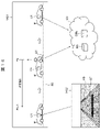
- FIG. 2 is a diagram showing an example of a scene in which structures on the road surface are detected using the external world recognition system according to this embodiment.
- the external world recognition system performs information aggregation processing and information distribution processing.
- the information aggregation process when a structure on the road surface is detected while the information providing vehicle C1 is traveling, the position information of the structure ST on the road surface is transmitted to the server NS, and the information is aggregated by the server NS.
- FIG. 2(a) is a diagram showing an example of information aggregation, and shows a scene in which a structure ST on the road surface is detected while driving in the daytime. If the three-dimensional measurement device of the information providing vehicle C1 is, for example, a stereo camera, the structure ST on the road surface can be easily and accurately detected during travel in bright daytime hours.
- the three-dimensional shape of the road surface unevenness is calculated by the stereo camera, the road surface structure ST is detected, and the relative position and height (shape) of the road surface structure ST with respect to the information providing vehicle C1 are calculated. is estimated. Then, the self-position information of the information providing vehicle C1 measured by the self-position measuring device 315 and the position information of the structure ST on the road surface are transmitted to the server NS by the communication device and stored in the server database DBs as driving experience information. . The position information of the structure ST on the road surface is stored separately for each structure ST on the road surface.
- the server NS receives the position information of the road surface structure ST from a plurality of information providing vehicles C1.
- the server NS aggregates the positional information of the structures ST on the road surface received from the plurality of information providing vehicles C1, and recalculates the positional information for each structure ST on the road surface. In this recalculation, statistical processing is performed to reduce errors in the position information and improve the accuracy of the position information.
- FIG. 2(b) is a diagram showing an example of information distribution, showing a scene in which a structure on the road surface is detected while driving at night.
- the stereo camera of the information-using vehicle C2 may have a low detection success rate and detection accuracy for the structure ST on the road surface, which is the object to be detected, when the vehicle is traveling in the dark at night.
- the stereo camera detects the structures on the road surface based on the positional information.
- the image processing method of the image processing unit for detecting objects is determined, and the structure ST on the road surface is detected by the determined image processing method.
- the detection algorithm such as performing highly accurate image recognition by narrowing the area where image processing is performed by the stereo camera.
- the detection parameters are changed such as by narrowing the range for detecting the peak height position of road unevenness and increasing the threshold value.
- the information-using vehicle C2 does not use the recognition result of the image recognition.
- vehicle control such as warning to passengers, suspension pressure, deceleration, steering, etc. is performed using the position information of the road surface structure ST distributed from the server NS.
- FIG. 3 is a functional block diagram of the information providing vehicle C1, the information using vehicle C2, and the server NS that constitute the external world recognition system of this embodiment.
- the information providing vehicle C1 provides information by passing over the stereo camera 312, which is an example of a three-dimensional measuring device that measures the three-dimensional shape of the road surface and detects structures on the road surface, and the structures ST on the road surface.
- Information is exchanged between a G sensor 313 that detects vehicle vibration applied to the vehicle C1, a self-position measuring device (position information acquisition means) 315 that measures the self coordinate position in the world coordinate system such as a GPS navigation device, and the server NS. It has a road-to-vehicle communication device 317 for transmitting and receiving.
- the information-using vehicle C2 has a stereo camera 322, a self-position measuring device (self-position measuring unit) 325, a road-to-vehicle communication device 324, and a G sensor 323. Further, based on the detection result of the stereo camera 322, A vehicle control device 326 that performs automatic brake control and inter-vehicle distance control ACC, a human-machine interface 327 that warns vehicle occupants, a vehicle route generation device 328 that generates a route to a destination, and information-using vehicle C2. It has a vehicle database DBc that stores information such as the coordinate position and the position and size of the structure ST on the road surface.
- the stereo camera 322 has a pair of left and right in-vehicle cameras that capture images in front of the vehicle, and a camera control unit that performs image processing of the in-vehicle cameras and captured images.
- the camera control section has hardware such as a CPU and a memory, and a software program executed by the hardware, and implements the control functions of the following sections through cooperation between the hardware and software.
- the camera control unit of the stereo camera 322 includes an image processing unit that performs image processing for detecting structures on the road surface from images captured by the vehicle-mounted camera, and based on the position information of the structures on the road surface ST received from the server NS. and an image processing method determination unit that changes the image processing method of the image processing unit.
- the server NS includes a communication device 302 that transmits and receives information to and from the road-to-vehicle communication device 317 of the information providing vehicle C1 and to and from the road-to-vehicle communication device 324 of the information-using vehicle C2.
- Statistical analysis of the server database DBs that collects and stores the position information of the provided road surface structure ST in a readable manner and the big data that includes vehicle information and traffic information stored in the server database DBs, It has a data analysis device 303 that generates driving experience information and maps it on a road-related map.
- FIG. 4 is a flowchart for explaining the content of information processing in the information providing vehicle and the server, and shows the content of processing for providing information from the information providing vehicle C1 to the server NS.
- the image pickup unit of the stereo camera 312 picks up an image in front of the vehicle to obtain a picked-up image (S401), and the image processing unit of the stereo camera 312 performs image processing on the picked-up image to generate a parallax image.
- the unevenness of the road surface which is a three-dimensional shape in front of the vehicle, is measured, and the structure ST on the road surface is detected based on the measurement results (S402).
- the stereo camera 312 acquires three-dimensional shapes such as speed bumps and road edge shapes on the road surface, road unevenness data, etc., and information on the positions of the structures ST on the road surface through image processing by the image processing unit.
- the image processing unit of the stereo camera 312 coordinates-transforms the position of the structure ST on the road surface obtained by image processing from the position relative to the own vehicle to the coordinate position of the world coordinate system. Specifically, position information in the world coordinate system corresponding to the imaging position of the own vehicle measured by the self-position measuring device 315 is acquired (S403), and position information in the world coordinate system of the structure ST on the road surface is generated. (S404). Then, the information providing vehicle C1 uses the road-vehicle communication device 317 to transmit the position information of the structure ST on the road surface after the coordinate conversion to the server NS.
- the server NS stores in the server database DBs the positional information of the plurality of road surface structures ST transmitted from the plurality of information providing vehicles C1 or from the same information providing vehicle C1 (S405).
- the server NS stores the position information of the structure ST on the road surface in the server database DBs
- the server NS recalculates the traffic experience information on the map at a predetermined timing and updates it to the latest information.
- the server NS receives the positional information of a plurality of structures ST on the road surface from the information providing vehicle C1
- the server NS organizes the information by adding or deleting the information, collects the information on the same position as the same information, and stores it in the server database. Store in DBs.
- the server NS statistically analyzes the positional information of the structures ST on the road surface transmitted from the plurality of information providing vehicles C1 and stored in the server database DBs as big data by the data analysis device 303, and creates and updates the driving experience information. , is mapped onto a road-related map, and stored in the server database DBs as traffic experience information on the map (S406).
- FIG. 5 is a flowchart for explaining a normal image processing method in a stereo camera, and shows an example of processing performed by the stereo camera of the information providing vehicle C1.
- a pair of left and right captured images are captured by the imaging unit of the stereo camera 312 (S501), and a parallax image is generated from the pair of captured images (S502). Then, an image processing area for image processing is set in the parallax image (S503).
- an image processing area for image processing is set in the parallax image (S503).
- an area on the tire traveling path through which the left and right tires of the information providing vehicle C1 pass is set as an image processing area.
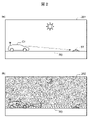
- FIG. 8 is a diagram showing an example of setting an image processing area in a parallax image, and is a diagram explaining a method of setting the image processing area.
- a parallax image 801 generated by imaging the front of the vehicle with a stereo camera shows a traveling road surface 811 of a road R0 and white lines 812 on both left and right sides thereof.
- Processing areas 821 and 822 are set along the vehicle traveling path. The processing areas 821 and 822 are set so as to extend in the depth direction (advance direction) with a predetermined width on the tire travel path through which the left and right tires pass as the vehicle travel path.
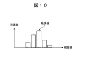
- FIG. 10 is a diagram for explaining a method of searching in the lateral direction to determine the parallax of unevenness of the road surface.
- the lateral search is performed over the entire depth direction of the processing areas 821 and 822 .
- the parallax values for each lateral search calculated in S504 are arranged in the depth direction of the processing area, and the peak position of the unevenness height of the road surface is calculated (S505). For example, a peak position whose height from the road surface reference plane has a value greater than a predetermined determination threshold value can be determined as the position of the structure on the road surface ST.
- a process of analyzing the stability of peak position determination is performed (S506).
- this stability analysis processing it is determined whether or not the peak position moves according to the movement of the own vehicle.
- the distance between the own vehicle and the structure ST on the road surface is calculated (S507), and the final output is produced (S508).
- S508 a process of outputting a warning to the occupants and an emergency braking signal to the vehicle control device is performed, and the vehicle control device controls the warning and emergency braking, but is not limited to this.
- the vehicle control device may issue an alarm or an emergency brake.
- FIG. 6 is a flow chart explaining the contents of information processing in the server NS and the information-using vehicle C2.
- the information-using vehicle C2 measures its own position with the self-position measuring device 325, and transmits the self-position information to the server NS (S601).
- the server NS searches the server database DBs and extracts the position information of structures on the road existing around the self-position of the information-using vehicle C2 (S602). . Then, the position information is distributed to the information-using vehicle C2 that has provided the self-position information.
- the information-using vehicle C2 When the information-using vehicle C2 receives the position information of the structures ST existing on the road surface around its own position from the server NS, it stores it in the vehicle database DBc (S603). Then, the stereo camera 322 picks up an image in front of the vehicle, acquires the picked-up image (S604), and performs image processing using the position information of the structure on the road surface ST received from the server NS stored in the vehicle database DBc. A structure ST on the road surface is detected (S605).
- the image processing method is determined based on the position information of the structure ST on the road surface received from the server NS. For example, first, a process of searching the vehicle database DBc using position information of structures on the road surface around the self-position measured by the self-position measuring device 325 is performed. When the road surface structure ST, which is the object to be detected, exists in the vicinity of the self position, the image processing method determination unit of the stereo camera 322 changes at least one of the image processing algorithm and parameters. done.
- the stereo camera 322 performs image processing using the changed algorithm and parameters, and detects the structure ST on the road surface.
- the stereo camera 322 changes the algorithm or parameters based on the position information of the structure ST on the road surface received from the server NS, analyzes the image processing area corresponding to the position in detail, and adjusts the detection accuracy. .
- the information-using vehicle C2 performs vehicle control using the detection result of the structure ST on the road surface by the stereo camera 322 (S606).
- vehicle control process of S606 for example, at least one of adjustment of the vehicle speed passing the road surface structure ST, route setting, and warning to the occupant is performed.
- the vehicle control device 326 searches the vehicle database DBc for information on the road surface structure ST around the self-position measured by the self-position measuring device 325, and searches the vehicle database DBc for information on the road surface structure ST that is stored corresponding to the road surface structure ST. When it is determined that the speed of the own vehicle exceeds the speed information, deceleration control is performed.
- the speed is decelerated to a speed at which the speed bump can be passed safely or comfortably, or the upper limit speed of the inter-vehicle distance control ACC is set. Change to a speed that you can safely or comfortably pass.
- the vehicle route generation device 328 sets a route so that the information-using vehicle C2 passes through a road or lane on which it can travel safely or comfortably.
- the human-machine interface 327 determines that the speed of the information-using vehicle C2 is excessive, it sounds a warning alarm or displays a warning on the monitor to warn the occupants.
- the damping value may be adjusted to suppress the behavior of the vehicle when passing through a speed bump.
- FIG. 7 is a flowchart for explaining the processing by the stereo camera of the information-using vehicle C2. The description of the configuration similar to that of the flowchart shown in FIG. 5 will be omitted.
- the stereo camera 322 changes the image processing method according to whether or not the structure ST on the road surface exists around its own position.
- the stereo camera 322 performs normal image processing using the same algorithm and parameters as those of the information providing vehicle C1 when the structure ST on the road surface does not exist around its own position.
- image processing is performed by changing at least one of the image processing algorithm and parameters as compared with the case where the road surface structure ST does not exist.
- FIG. 9 is a diagram for explaining an image processing method using position information, and shows an example of narrowing down the image processing area.
- the image processing method determining unit of the stereo camera 322 performs a process of narrowing down the image processing area of road unevenness based on the positional information of the road surface structure ST received from the server NS.
- a second image processing area 911 corresponding to the position of the structure ST on the road surface on the tire traveling path , 912 is performed.
- the self-position of the vehicle estimated by receiving radio waves from GPS or base stations, the update cycle of GPS information, the vehicle speed at that time, the position information of the road surface structure ST received from the server NS, the position information of the road surface structure ST received from the server NS, map estimation error (depending on radio wave conditions and the number of detected base stations), information transmission in the in-vehicle communication environment, and time-world coordinate transformation (imaging and Captured by a camera by converting positional information of an object into a three-dimensional to two-dimensional coordinate system that considers time-varying information such as position measurement and vehicle speed, and the coordinate system of the map and the imaging coordinate system of the camera.
- the second image processing areas 911 and 912 are set shorter in length in the depth direction than the first image processing areas 821 and 822, and have a size and shape that cover the road surface structure ST in the parallax image. there is In this way, by narrowing down the image processing area to make it smaller, the image processing load can be reduced. Therefore, more detailed image processing can be performed in a short time with limited hardware resources, and the structure ST on the road surface, which is the object to be detected, can be detected with high accuracy.
- FIG. 11 is a diagram showing the peak detection results of road surface irregularities, showing the detected values of the road surface height in the depth direction of the tire traveling path.
- the horizontal axis is the distance (m) in the depth direction
- the vertical axis is the road surface height (cm) detected by the stereo camera 322 .
- the image processing method determination unit of the stereo camera 322 determines the peak position of the road unevenness in the first detection range set along the depth direction of the tire travel path when the structure ST on the road surface does not exist around the self position. However, when the structure ST on the road surface exists around the self position, the image processing algorithm or parameters of the image processing unit are changed, and a second detection range corresponding to the position of the structure ST on the road surface on the tire traveling path is detected. , the peak position of road unevenness is determined (S505A).
- the image processing method determination unit of the stereo camera 322 sets the determination threshold for determining the peak position of road surface unevenness in the second detection range to be higher than the determination threshold for determining the peak position of road surface unevenness in the first detection range.
- a large value is set (S505A).
- a process of outputting an alarm or emergency braking signal to the vehicle control device, or a process of outputting only information on the distance between the own vehicle and the structure ST on the road surface is performed. Further, it is determined whether or not the reliability of the captured image captured by the stereo camera 322 is equal to or higher than the threshold. For example, when the reliability is lower than the threshold value due to the weather or external light conditions, the processing in S501 to S507 is skipped, and the final output is made based on the position information of the structure ST on the road surface distributed from the server NS. Based on the output, vehicle control such as warning to passengers, suspension pressure, deceleration, and steering is performed.
- step S509A for calculating verification information of the structure ST on the road surface is provided.
- the stereo camera 322 converts the position of the structure ST on the road surface detected by the image processing into the coordinate position of the world coordinate system using the self-position information obtained by the self-position measuring device 325. , acquires information on the position where the behavior of the vehicle is detected when the vehicle passes over the structure ST on the road surface.
- the process of converting the position of the structure ST on the road surface into the world coordinates is based on the distance to the structure ST on the road surface detected by image processing, (1) the vehicle speed at the time of imaging, and (2) the imaging unit of the stereo camera 322. (3) self-location information by the self-location measurement device 325; (4) acquisition timing of self-location information by the self-location measurement device 325; (5) communication delay speed of in-vehicle equipment; Time-world coordinate conversion processing converts position information into a three-dimensional to two-dimensional coordinate system, taking into consideration time-varying information such as imaging, position measurement, and vehicle speed, as well as the coordinate system of the map and the coordinate system captured by the camera. is.
- the behavior of the vehicle when the vehicle passes over the structure ST on the road surface can be detected by the stereo camera 322 by detecting the vertical movement of the captured image, and by the vehicle-mounted sensors such as the G sensor, pitching, vertical acceleration, A change in suspension pressure may be detected.
- the position of the road surface structure ST detected by the stereo camera 322 of the information using vehicle C2 is verified from the own vehicle behavior, and the verification information is transmitted to the server NS.
- the server NS can improve the estimation accuracy of the position of the road surface structure ST using the verification information.
- FIG. 13 is a flow chart for explaining the processing contents of the external world recognition system in the second embodiment
- FIG. 14 is a diagram showing an example of a situation in which the processing shown in FIG. 13 is performed.
- a characteristic feature of this embodiment is that although the information providing vehicle C1 cannot detect the structure ST on the road surface with the stereo camera 312, it detects vehicle vibration in the vertical direction due to passing over the structure ST on the road surface. By detecting the vibration, the server NS performs image processing using an image obtained by picking up the vibration detection position.
- the stereo camera 312 of the information providing vehicle C1 acquires captured images captured during travel and stores them in the vehicle database (S1301). Then, for example, when the G sensor 313 detects vibration equal to or greater than a preset threshold for detecting vertical vehicle vibration due to passing over the road surface structure ST (S1302), the self-position measuring device detects The position information of the vibration detection point Pn is acquired based on the self-position information (S1303).
- the method of detecting vehicle vibration is not limited to the G sensor 313. For example, vertical movement of images captured by the stereo camera 312, pitching by an in-vehicle sensor such as a gyro sensor, vertical acceleration, and changes in suspension pressure are used. good too.
- the stereo camera 312 searches the inside of the vehicle database and extracts the captured image of the vibration detection point Pn from the captured images stored in the vehicle database (S1304).
- an image captured when t time goes back from the time when the vehicle vibration in the vertical direction is detected to the position Pn-1 where the stereo camera 312 captures the image of the vibration detection point Pn. is extracted as an image in which the vibration detection point Pn is captured.
- the road-to-vehicle communication device 317 receives from the stereo camera 312 the information of the vibration detection point Pn and the imaged image of the point, and transmits the information to the server NS.
- the data analysis device 303 detects the structure ST on the road surface from the captured image of the vibration detection point Pn.
- image processing is performed (S1305).
- the image processing performed by the server NS differs from the image processing performed by the stereo camera 312 in terms of processing content, and is more detailed and advanced than the image processing performed in the stereo camera 312 .
- the server NS does not have processing time restrictions and has higher specifications than the stereo camera 312 and abundant hardware and software resources. Image processing of content can be performed. Therefore, it is possible to detect the road surface structure ST that could not be detected by the stereo camera 312, and to verify the reason why the stereo camera 312 could not detect it.
- the server NS stores the detection result of the road surface structure ST by the image processing of the data analysis device 303 and the position information of the vibration detection point Pn in the server database DBs (S1306).
- the position information is analyzed and recalculated (S1307).
- the structure ST on the road surface which could not be detected by the stereo camera 312
- the structure ST on the road surface can be detected by the image processing in the server NS, and the road surface stored in the server database DBs can be detected.
- the accuracy of the position information of the upper structure ST can be made higher.
- the image processing for verification is performed in the server NS.
- Image processing for verification may be performed in the server NS also when the structure ST on the road surface is detected by .
- the case of the information providing vehicle C1 has been described as an example. may be used to perform image processing in the server NS.
- FIG. 15 is a flowchart for explaining the processing contents of the external world recognition system in the third embodiment, and shows an analysis method based on the information on the position of structures on the road surface and vehicle vibration.
- a characteristic feature of this embodiment is that, in addition to the positional information of the structure ST on the road surface, information about the degree of influence on vehicle vibration when the vehicle actually passes is stored in the server, and the information-using vehicle C2 detects the road surface. It is used for vehicle control when passing over the upper structure ST.
- the information providing vehicle C1 acquires a captured image (S1501), and performs image processing to detect the structure ST on the road surface, determine the distance to the structure ST on the road surface, and the height of the structure ST from the road surface reference plane. is measured (S1502).
- the road surface reference plane can be obtained, for example, from the average position of road unevenness in the depth direction.
- the information providing vehicle C1 uses the G sensor 323 to detect vibration when it passes over the structure ST on the road surface (S1503), and acquires position information of the vibration detection point (S1504).
- the degree of influence on the vehicle vibration is calculated based on the magnitude of the vibration detected by the G sensor 323, and the position information of the structure ST on the road surface, the position of the vibration detection point, and the information on the degree of influence on the vehicle vibration are obtained.
- the information is sent to the server NS, and the server NS stores this information in the server database DBs (S1505).
- the server NS aggregates the position information of the road surface structure ST stored in the server database DBs, the position of the vibration detection point, and the degree of influence on the vehicle vibration, and the data analysis device 303 statistically analyzes the big data. , update the driving experience information, map it on the road-related map, and create the traffic experience information on the map.
- the server NS After storing the position information of the road surface structure ST in the server database DBs, the server NS recalculates the traffic experience information on the map at a predetermined timing in order to update the information to the latest information (S1506).
- the server NS When the server NS receives the self-position information from the information providing vehicle C1, the server NS uses the position information of the structure ST existing on the road surface around the self-position of the information-using vehicle C2 and the information on the degree of influence on the vehicle vibration. Send to vehicle C2.
- the information-using vehicle C2 slows down the running speed and adjusts the suspension based on the position information of the road surface structures ST existing around its own position and the information on the degree of influence on the vehicle vibration so as to reduce the vibration of the vehicle. It performs vehicle control such as damping force adjustment.
- the information on the degree of influence of the vehicle vibration by the structure ST on the road surface can be provided to the information-using vehicle C2. can be performed, and the passenger's riding comfort can be improved.
- C1 Information providing vehicle C2 Information using vehicle (own vehicle) NS server (external server) DBs Server database DBc Vehicle database ST On-road structure 322 Stereo camera 323 G sensor 324 Road-to-vehicle communication device (vehicle communication unit) 325 self-position measuring devices 821, 822 first image processing areas 911, 912 second image processing areas
Landscapes
- Engineering & Computer Science (AREA)
- Physics & Mathematics (AREA)
- General Physics & Mathematics (AREA)
- Computing Systems (AREA)
- Life Sciences & Earth Sciences (AREA)
- Analytical Chemistry (AREA)
- Chemical & Material Sciences (AREA)
- Atmospheric Sciences (AREA)
- Health & Medical Sciences (AREA)
- Operations Research (AREA)
- Multimedia (AREA)
- Signal Processing (AREA)
- Computer Networks & Wireless Communication (AREA)
- Biomedical Technology (AREA)
- General Health & Medical Sciences (AREA)
- Theoretical Computer Science (AREA)
- Business, Economics & Management (AREA)
- Accounting & Taxation (AREA)
- Development Economics (AREA)
- Economics (AREA)
- General Business, Economics & Management (AREA)
- Traffic Control Systems (AREA)
- Length Measuring Devices By Optical Means (AREA)
- Image Analysis (AREA)
Priority Applications (4)
| Application Number | Priority Date | Filing Date | Title |
|---|---|---|---|
| DE112022001520.9T DE112022001520T5 (de) | 2021-06-18 | 2022-02-09 | Aussenerkennungssystem |
| JP2023529480A JP7646834B2 (ja) | 2021-06-18 | 2022-02-09 | 外界認識システム |
| CN202280032688.4A CN117396933A (zh) | 2021-06-18 | 2022-02-09 | 外界识别系统 |
| JP2025034611A JP2025102782A (ja) | 2021-06-18 | 2025-03-05 | 外界認識システム |
Applications Claiming Priority (2)
| Application Number | Priority Date | Filing Date | Title |
|---|---|---|---|
| JP2021-101340 | 2021-06-18 | ||
| JP2021101340 | 2021-06-18 |
Publications (1)
| Publication Number | Publication Date |
|---|---|
| WO2022264492A1 true WO2022264492A1 (ja) | 2022-12-22 |
Family
ID=84526955
Family Applications (1)
| Application Number | Title | Priority Date | Filing Date |
|---|---|---|---|
| PCT/JP2022/005011 Ceased WO2022264492A1 (ja) | 2021-06-18 | 2022-02-09 | 外界認識システム |
Country Status (4)
| Country | Link |
|---|---|
| JP (2) | JP7646834B2 (https=) |
| CN (1) | CN117396933A (https=) |
| DE (1) | DE112022001520T5 (https=) |
| WO (1) | WO2022264492A1 (https=) |
Cited By (2)
| Publication number | Priority date | Publication date | Assignee | Title |
|---|---|---|---|---|
| CN118168606A (zh) * | 2024-05-11 | 2024-06-11 | 四川瞪羚腾光科技有限公司 | 一种车载移动测量的视觉引导方法及系统 |
| WO2025197282A1 (ja) * | 2024-03-18 | 2025-09-25 | 三菱自動車工業株式会社 | 車両周辺画像の画像認識システム |
Families Citing this family (1)
| Publication number | Priority date | Publication date | Assignee | Title |
|---|---|---|---|---|
| DE102024200468B3 (de) * | 2024-01-18 | 2025-06-05 | Volkswagen Aktiengesellschaft | Steuergerät für ein Kraftfahrzeug und Verfahren eines Servers zum Erstellen von Kartendaten |
Citations (3)
| Publication number | Priority date | Publication date | Assignee | Title |
|---|---|---|---|---|
| JP2008249480A (ja) * | 2007-03-30 | 2008-10-16 | Aisin Aw Co Ltd | 画像認識装置及び画像認識方法 |
| EP3611068A1 (en) * | 2018-08-16 | 2020-02-19 | Continental Automotive GmbH | Driving assistance method and device, and vehicle |
| WO2020036039A1 (ja) * | 2018-08-13 | 2020-02-20 | 日立オートモティブシステムズ株式会社 | ステレオカメラ装置 |
Family Cites Families (6)
| Publication number | Priority date | Publication date | Assignee | Title |
|---|---|---|---|---|
| JP2010287044A (ja) | 2009-06-11 | 2010-12-24 | Isuzu Motors Ltd | 道路情報提供装置およびナビゲーション装置 |
| JP5776545B2 (ja) * | 2011-12-28 | 2015-09-09 | 富士通株式会社 | 路面調査プログラム及び路面調査装置 |
| JP2015229433A (ja) * | 2014-06-05 | 2015-12-21 | 太平洋工業株式会社 | 路面状態検出装置及び路面状態検出システム |
| JP6981305B2 (ja) * | 2018-02-27 | 2021-12-15 | トヨタ自動車株式会社 | 情報処理装置、画像配信システム、情報処理方法、及びプログラム |
| JP7172619B2 (ja) * | 2018-04-25 | 2022-11-16 | トヨタ自動車株式会社 | 路面状態推定装置及び路面状態推定方法 |
| JP2020194468A (ja) * | 2019-05-30 | 2020-12-03 | アイシン・エィ・ダブリュ株式会社 | 路面状態特定システム、路面状態特定装置及びコンピュータプログラム |
-
2022
- 2022-02-09 CN CN202280032688.4A patent/CN117396933A/zh active Pending
- 2022-02-09 WO PCT/JP2022/005011 patent/WO2022264492A1/ja not_active Ceased
- 2022-02-09 JP JP2023529480A patent/JP7646834B2/ja active Active
- 2022-02-09 DE DE112022001520.9T patent/DE112022001520T5/de active Pending
-
2025
- 2025-03-05 JP JP2025034611A patent/JP2025102782A/ja active Pending
Patent Citations (3)
| Publication number | Priority date | Publication date | Assignee | Title |
|---|---|---|---|---|
| JP2008249480A (ja) * | 2007-03-30 | 2008-10-16 | Aisin Aw Co Ltd | 画像認識装置及び画像認識方法 |
| WO2020036039A1 (ja) * | 2018-08-13 | 2020-02-20 | 日立オートモティブシステムズ株式会社 | ステレオカメラ装置 |
| EP3611068A1 (en) * | 2018-08-16 | 2020-02-19 | Continental Automotive GmbH | Driving assistance method and device, and vehicle |
Cited By (2)
| Publication number | Priority date | Publication date | Assignee | Title |
|---|---|---|---|---|
| WO2025197282A1 (ja) * | 2024-03-18 | 2025-09-25 | 三菱自動車工業株式会社 | 車両周辺画像の画像認識システム |
| CN118168606A (zh) * | 2024-05-11 | 2024-06-11 | 四川瞪羚腾光科技有限公司 | 一种车载移动测量的视觉引导方法及系统 |
Also Published As
| Publication number | Publication date |
|---|---|
| JP2025102782A (ja) | 2025-07-08 |
| CN117396933A (zh) | 2024-01-12 |
| DE112022001520T5 (de) | 2024-01-11 |
| JP7646834B2 (ja) | 2025-03-17 |
| JPWO2022264492A1 (https=) | 2022-12-22 |
Similar Documents
| Publication | Publication Date | Title |
|---|---|---|
| US10384679B2 (en) | Travel control method and travel control apparatus | |
| US11970183B2 (en) | AV path planning with calibration information | |
| JP5761162B2 (ja) | 車両位置推定装置 | |
| JP6219312B2 (ja) | 道路の車線の車線交通路内の車両の位置を決定する方法、並びに2つの車両間の整列及び衝突リスクを検知する方法 | |
| CN110087964B (zh) | 车辆控制系统、车辆控制方法及存储介质 | |
| US11507107B2 (en) | Map information system | |
| CN106996793A (zh) | 地图更新判定系统 | |
| JP7147442B2 (ja) | 地図情報システム | |
| JP7646834B2 (ja) | 外界認識システム | |
| US20200073405A1 (en) | Vehicle navigation and control | |
| JPWO2018225596A1 (ja) | 情報処理装置 | |
| JP2019203823A (ja) | 走行計画生成装置、走行計画生成方法、及び制御プログラム | |
| JP7170637B2 (ja) | 車両制御システム、車両制御方法、およびプログラム | |
| CN114779790A (zh) | 识别障碍物方法、装置、车辆、服务器、存储介质及芯片 | |
| US20220234589A1 (en) | Surface guided vehicle behavior | |
| US20180329421A1 (en) | Road link information updating device and vehicle control system | |
| KR20210029323A (ko) | 정밀 지도를 이용한 센서 퓨전의 인지 성능 향상을 위한 장치 및 방법 | |
| CN115205365A (zh) | 车辆距离检测方法、装置、车辆、可读存储介质及芯片 | |
| JP2020175893A (ja) | 自動運転システム、自動運転装置、自動運転方法 | |
| US12271998B2 (en) | Spatially and temporally consistent ground modelling with information fusion | |
| JP2018106490A (ja) | 自動運転装置 | |
| JP2018198004A (ja) | 通信装置、通信システム、及び通信方法 | |
| CN115082886B (zh) | 目标检测的方法、装置、存储介质、芯片及车辆 | |
| JP2023122597A (ja) | 情報処理装置、情報処理方法及びプログラム | |
| CN115220449A (zh) | 路径规划的方法、装置、存储介质、芯片及车辆 |
Legal Events
| Date | Code | Title | Description |
|---|---|---|---|
| 121 | Ep: the epo has been informed by wipo that ep was designated in this application |
Ref document number: 22824493 Country of ref document: EP Kind code of ref document: A1 |
|
| WWE | Wipo information: entry into national phase |
Ref document number: 2023529480 Country of ref document: JP |
|
| WWE | Wipo information: entry into national phase |
Ref document number: 202280032688.4 Country of ref document: CN |
|
| WWE | Wipo information: entry into national phase |
Ref document number: 112022001520 Country of ref document: DE |
|
| WWE | Wipo information: entry into national phase |
Ref document number: 202317080651 Country of ref document: IN |
|
| 122 | Ep: pct application non-entry in european phase |
Ref document number: 22824493 Country of ref document: EP Kind code of ref document: A1 |
|
| WWG | Wipo information: grant in national office |
Ref document number: 202317080651 Country of ref document: IN |