WO2022264428A1 - Terminal, and radio communication method - Google Patents
Terminal, and radio communication method Download PDFInfo
- Publication number
- WO2022264428A1 WO2022264428A1 PCT/JP2021/023273 JP2021023273W WO2022264428A1 WO 2022264428 A1 WO2022264428 A1 WO 2022264428A1 JP 2021023273 W JP2021023273 W JP 2021023273W WO 2022264428 A1 WO2022264428 A1 WO 2022264428A1
- Authority
- WO
- WIPO (PCT)
- Prior art keywords
- tboms
- terminal
- information
- slots
- transmission
- Prior art date
Links
- 238000000034 method Methods 0.000 title claims abstract description 161
- 238000004891 communication Methods 0.000 title claims description 51
- 230000005540 biological transmission Effects 0.000 claims abstract description 143
- 238000010586 diagram Methods 0.000 description 22
- 238000012545 processing Methods 0.000 description 15
- 230000006870 function Effects 0.000 description 10
- 230000011664 signaling Effects 0.000 description 9
- 238000004364 calculation method Methods 0.000 description 7
- 238000013468 resource allocation Methods 0.000 description 7
- 238000010187 selection method Methods 0.000 description 7
- 230000008054 signal transmission Effects 0.000 description 7
- 101100243399 Caenorhabditis elegans pept-2 gene Proteins 0.000 description 5
- 238000005516 engineering process Methods 0.000 description 5
- 230000003595 spectral effect Effects 0.000 description 5
- 238000010295 mobile communication Methods 0.000 description 4
- 230000008569 process Effects 0.000 description 4
- 101100189913 Caenorhabditis elegans pept-1 gene Proteins 0.000 description 3
- MKYBYDHXWVHEJW-UHFFFAOYSA-N N-[1-oxo-1-(2,4,6,7-tetrahydrotriazolo[4,5-c]pyridin-5-yl)propan-2-yl]-2-[[3-(trifluoromethoxy)phenyl]methylamino]pyrimidine-5-carboxamide Chemical compound O=C(C(C)NC(=O)C=1C=NC(=NC=1)NCC1=CC(=CC=C1)OC(F)(F)F)N1CC2=C(CC1)NN=N2 MKYBYDHXWVHEJW-UHFFFAOYSA-N 0.000 description 3
- NIPNSKYNPDTRPC-UHFFFAOYSA-N N-[2-oxo-2-(2,4,6,7-tetrahydrotriazolo[4,5-c]pyridin-5-yl)ethyl]-2-[[3-(trifluoromethoxy)phenyl]methylamino]pyrimidine-5-carboxamide Chemical compound O=C(CNC(=O)C=1C=NC(=NC=1)NCC1=CC(=CC=C1)OC(F)(F)F)N1CC2=C(CC1)NN=N2 NIPNSKYNPDTRPC-UHFFFAOYSA-N 0.000 description 3
- 125000004122 cyclic group Chemical group 0.000 description 3
- 238000013507 mapping Methods 0.000 description 3
- VZSRBBMJRBPUNF-UHFFFAOYSA-N 2-(2,3-dihydro-1H-inden-2-ylamino)-N-[3-oxo-3-(2,4,6,7-tetrahydrotriazolo[4,5-c]pyridin-5-yl)propyl]pyrimidine-5-carboxamide Chemical compound C1C(CC2=CC=CC=C12)NC1=NC=C(C=N1)C(=O)NCCC(N1CC2=C(CC1)NN=N2)=O VZSRBBMJRBPUNF-UHFFFAOYSA-N 0.000 description 2
- 230000009471 action Effects 0.000 description 2
- 230000002776 aggregation Effects 0.000 description 2
- 238000004220 aggregation Methods 0.000 description 2
- 239000000969 carrier Substances 0.000 description 2
- 230000008859 change Effects 0.000 description 2
- 230000008878 coupling Effects 0.000 description 2
- 238000010168 coupling process Methods 0.000 description 2
- 238000005859 coupling reaction Methods 0.000 description 2
- 230000003247 decreasing effect Effects 0.000 description 2
- 230000007774 longterm Effects 0.000 description 2
- 230000003287 optical effect Effects 0.000 description 2
- OHVLMTFVQDZYHP-UHFFFAOYSA-N 1-(2,4,6,7-tetrahydrotriazolo[4,5-c]pyridin-5-yl)-2-[4-[2-[[3-(trifluoromethoxy)phenyl]methylamino]pyrimidin-5-yl]piperazin-1-yl]ethanone Chemical compound N1N=NC=2CN(CCC=21)C(CN1CCN(CC1)C=1C=NC(=NC=1)NCC1=CC(=CC=C1)OC(F)(F)F)=O OHVLMTFVQDZYHP-UHFFFAOYSA-N 0.000 description 1
- HMUNWXXNJPVALC-UHFFFAOYSA-N 1-[4-[2-(2,3-dihydro-1H-inden-2-ylamino)pyrimidin-5-yl]piperazin-1-yl]-2-(2,4,6,7-tetrahydrotriazolo[4,5-c]pyridin-5-yl)ethanone Chemical compound C1C(CC2=CC=CC=C12)NC1=NC=C(C=N1)N1CCN(CC1)C(CN1CC2=C(CC1)NN=N2)=O HMUNWXXNJPVALC-UHFFFAOYSA-N 0.000 description 1
- LDXJRKWFNNFDSA-UHFFFAOYSA-N 2-(2,4,6,7-tetrahydrotriazolo[4,5-c]pyridin-5-yl)-1-[4-[2-[[3-(trifluoromethoxy)phenyl]methylamino]pyrimidin-5-yl]piperazin-1-yl]ethanone Chemical compound C1CN(CC2=NNN=C21)CC(=O)N3CCN(CC3)C4=CN=C(N=C4)NCC5=CC(=CC=C5)OC(F)(F)F LDXJRKWFNNFDSA-UHFFFAOYSA-N 0.000 description 1
- WZFUQSJFWNHZHM-UHFFFAOYSA-N 2-[4-[2-(2,3-dihydro-1H-inden-2-ylamino)pyrimidin-5-yl]piperazin-1-yl]-1-(2,4,6,7-tetrahydrotriazolo[4,5-c]pyridin-5-yl)ethanone Chemical compound C1C(CC2=CC=CC=C12)NC1=NC=C(C=N1)N1CCN(CC1)CC(=O)N1CC2=C(CC1)NN=N2 WZFUQSJFWNHZHM-UHFFFAOYSA-N 0.000 description 1
- JQMFQLVAJGZSQS-UHFFFAOYSA-N 2-[4-[2-(2,3-dihydro-1H-inden-2-ylamino)pyrimidin-5-yl]piperazin-1-yl]-N-(2-oxo-3H-1,3-benzoxazol-6-yl)acetamide Chemical compound C1C(CC2=CC=CC=C12)NC1=NC=C(C=N1)N1CCN(CC1)CC(=O)NC1=CC2=C(NC(O2)=O)C=C1 JQMFQLVAJGZSQS-UHFFFAOYSA-N 0.000 description 1
- IHCCLXNEEPMSIO-UHFFFAOYSA-N 2-[4-[2-(2,3-dihydro-1H-inden-2-ylamino)pyrimidin-5-yl]piperidin-1-yl]-1-(2,4,6,7-tetrahydrotriazolo[4,5-c]pyridin-5-yl)ethanone Chemical compound C1C(CC2=CC=CC=C12)NC1=NC=C(C=N1)C1CCN(CC1)CC(=O)N1CC2=C(CC1)NN=N2 IHCCLXNEEPMSIO-UHFFFAOYSA-N 0.000 description 1
- YLZOPXRUQYQQID-UHFFFAOYSA-N 3-(2,4,6,7-tetrahydrotriazolo[4,5-c]pyridin-5-yl)-1-[4-[2-[[3-(trifluoromethoxy)phenyl]methylamino]pyrimidin-5-yl]piperazin-1-yl]propan-1-one Chemical compound N1N=NC=2CN(CCC=21)CCC(=O)N1CCN(CC1)C=1C=NC(=NC=1)NCC1=CC(=CC=C1)OC(F)(F)F YLZOPXRUQYQQID-UHFFFAOYSA-N 0.000 description 1
- CONKBQPVFMXDOV-QHCPKHFHSA-N 6-[(5S)-5-[[4-[2-(2,3-dihydro-1H-inden-2-ylamino)pyrimidin-5-yl]piperazin-1-yl]methyl]-2-oxo-1,3-oxazolidin-3-yl]-3H-1,3-benzoxazol-2-one Chemical compound C1C(CC2=CC=CC=C12)NC1=NC=C(C=N1)N1CCN(CC1)C[C@H]1CN(C(O1)=O)C1=CC2=C(NC(O2)=O)C=C1 CONKBQPVFMXDOV-QHCPKHFHSA-N 0.000 description 1
- DFGKGUXTPFWHIX-UHFFFAOYSA-N 6-[2-[4-[2-(2,3-dihydro-1H-inden-2-ylamino)pyrimidin-5-yl]piperazin-1-yl]acetyl]-3H-1,3-benzoxazol-2-one Chemical compound C1C(CC2=CC=CC=C12)NC1=NC=C(C=N1)N1CCN(CC1)CC(=O)C1=CC2=C(NC(O2)=O)C=C1 DFGKGUXTPFWHIX-UHFFFAOYSA-N 0.000 description 1
- AFCARXCZXQIEQB-UHFFFAOYSA-N N-[3-oxo-3-(2,4,6,7-tetrahydrotriazolo[4,5-c]pyridin-5-yl)propyl]-2-[[3-(trifluoromethoxy)phenyl]methylamino]pyrimidine-5-carboxamide Chemical compound O=C(CCNC(=O)C=1C=NC(=NC=1)NCC1=CC(=CC=C1)OC(F)(F)F)N1CC2=C(CC1)NN=N2 AFCARXCZXQIEQB-UHFFFAOYSA-N 0.000 description 1
- 101150069124 RAN1 gene Proteins 0.000 description 1
- 101100355633 Salmo salar ran gene Proteins 0.000 description 1
- 230000006978 adaptation Effects 0.000 description 1
- 238000003491 array Methods 0.000 description 1
- 239000003795 chemical substances by application Substances 0.000 description 1
- 230000007423 decrease Effects 0.000 description 1
- 230000001934 delay Effects 0.000 description 1
- 230000009977 dual effect Effects 0.000 description 1
- 239000000835 fiber Substances 0.000 description 1
- 238000001914 filtration Methods 0.000 description 1
- 239000006249 magnetic particle Substances 0.000 description 1
- 238000007726 management method Methods 0.000 description 1
- 230000007246 mechanism Effects 0.000 description 1
- 238000012986 modification Methods 0.000 description 1
- 230000004048 modification Effects 0.000 description 1
- 230000002093 peripheral effect Effects 0.000 description 1
- 230000011218 segmentation Effects 0.000 description 1
- 238000013519 translation Methods 0.000 description 1
- 230000001960 triggered effect Effects 0.000 description 1
Images


Classifications
-
- H—ELECTRICITY
- H04—ELECTRIC COMMUNICATION TECHNIQUE
- H04W—WIRELESS COMMUNICATION NETWORKS
- H04W72/00—Local resource management
- H04W72/04—Wireless resource allocation
- H04W72/044—Wireless resource allocation based on the type of the allocated resource
- H04W72/0446—Resources in time domain, e.g. slots or frames
-
- H—ELECTRICITY
- H04—ELECTRIC COMMUNICATION TECHNIQUE
- H04W—WIRELESS COMMUNICATION NETWORKS
- H04W72/00—Local resource management
- H04W72/12—Wireless traffic scheduling
- H04W72/1263—Mapping of traffic onto schedule, e.g. scheduled allocation or multiplexing of flows
- H04W72/1268—Mapping of traffic onto schedule, e.g. scheduled allocation or multiplexing of flows of uplink data flows
Definitions
- the present disclosure relates to terminals and wireless communication methods.
- LTE Long Term Evolution
- UMTS Universal Mobile Telecommunication System
- LTE-A Long Term Evolution-Advanced
- FAA Future Radio Access
- 5G 5th generation mobile communication system
- 5G+ 5th generation mobile communication system
- New-RAT Radio Access Technology
- NR Radio
- NR considers how to handle blocks of information (e.g., transport blocks (TB)) that are transmitted over multiple radio resources (e.g., physical uplink shared channels assigned to multiple slots).
- blocks of information e.g., transport blocks (TB)
- radio resources e.g., physical uplink shared channels assigned to multiple slots.
- One aspect of the present disclosure provides a terminal and wireless communication method capable of determining an appropriate size for blocks of information to be transmitted over multiple wireless resources.
- a terminal multiplies a second size of an information block to be transmitted in a physical uplink shared channel in one time resource unit by a coefficient, and the physical a control unit for determining a first size of an information block to be transmitted in a transmission scheme for transmitting information via an uplink shared channel; and transmitting an information block having the first size in units of the plurality of time resources. and a transmission unit for
- a wireless communication method spans a plurality of time resource units by multiplying a second size of an information block transmitted in a physical uplink shared channel in one time resource unit by a coefficient. determining a first size of an information block to be transmitted in a transmission scheme for transmitting information over the physical uplink shared channel, and transmitting the information block having the first size in the plurality of time resource units; .
- FIG. 4 is a diagram showing an example of PUSCH allocation by TBoMS; 1 is a diagram showing an example of a radio communication system according to an embodiment; FIG. 2 is a block diagram showing an example of the configuration of a base station according to one embodiment; FIG. 1 is a block diagram showing an example of a configuration of a terminal according to one embodiment; FIG. FIG. 10 is a diagram showing an example of determination method 1; FIG. 4 is a diagram illustrating an example of repeated transmission of TBoMS; FIG. 10 is a diagram showing an example of bit selection in selection method 1 of transmission method 2; FIG. 10 is a diagram showing an example of bit selection in selection method 1 of transmission method 2; FIG.
- FIG. 4 is a diagram showing an example of the relationship between RV ids and TBoMS transmission opportunities;
- FIG. 11 is a diagram showing an example of bit selection in transmission method 3;
- FIG. 11 is a diagram showing an example of bit selection in transmission method 3; It is a figure which shows an example of the hardware configuration of the base station and terminal which concern on one Embodiment.
- Non-Patent Document 2 Physical Uplink shared channels allocated to multiple slots, specifically, TB processing over multi-slot PUSCH (PUSCH (Physical Uplink Shared Channel) for processing transport blocks (TB) via PUSCH (Physical Uplink Shared Channel) It has been agreed to study a method for determining time resources for TBoMS (Non-Patent Document 2).
- PUSCH Physical Uplink Shared Channel
- PUSCH Physical Uplink Shared Channel
- TBoMS can be interpreted as a technique for transmitting one transport block using multiple slots.
- FIG. 1 is a diagram showing an example of PUSCH allocation by TBoMS. Specifically, FIG. 1 shows an example of PUSCH allocation by TBoMS according to Type A repetition like TDRA (Time Domain Resource Allocation) and Type B repetition like TDRA. Note that Type A, B may mean Repetition type A, B.
- Type A, B may mean Repetition type A, B.
- TBoMS can have the following advantages.
- the coding rate (code rate) decreases. • The gain of channel coding is improved by lengthening the code sequence. ⁇ Compared to the case of transmitting multiple TB, the amount of upper layer headers can be reduced.
- TBS size of TB
- N RE number of REs
- N info number of information bits
- TBS corresponding to PUSCH allocated across multiple slots (which may be consecutive). For example, by determining the appropriate TBS, it is possible to achieve the specified target code rate even when transmitting TBoMS. In other words, by determining the appropriate TBS, the actual code rate during TBoMS transmission can be brought closer to the specified target code rate. Also, by determining an appropriate TBS, the efficiency of coverage extension by TBoMS can be improved.
- FIG. 2 is a diagram showing an example of the radio communication system 10 according to the embodiment.
- the radio communication system 10 may be a radio communication system according to New Radio (NR).
- the radio communication system 10 includes a Next Generation-Radio Access Network 20 (hereinafter referred to as NG-RAN 20) and a terminal 200.
- NG-RAN 20 Next Generation-Radio Access Network 20
- the wireless communication system 10 may be a wireless communication system conforming to a scheme called 5G, Beyond 5G, 5G Evolution, or 6G.
- NG-RAN 20 includes base stations 100 (base station 100A and base station 100B). Note that the number of base stations 100 and the number of terminals 200 are not limited to the example shown in FIG.
- the NG-RAN 20 includes multiple NG-RAN Nodes, specifically gNBs (or ng-eNBs), and is connected to a 5G-compliant core network (5GC, not shown). Note that the NG-RAN 20 and 5GC may simply be referred to as a "network”.
- the base station 100 may also be called an NG-RAN Node, ng-eNB, eNodeB (eNB), or gNodeB (gNB).
- Terminal 200 may be called User Equipment (UE).
- base station 100 may be regarded as a device included in a network to which terminal 200 connects.
- the base station 100 performs wireless communication with the terminal 200.
- the wireless communication performed complies with NR.
- At least one of the base station 100 and the terminal 200 uses Massive MIMO (Multiple-Input Multiple-Output) to generate beams (BM) with higher directivity by controlling radio signals transmitted from a plurality of antenna elements. You can respond.
- at least one of base station 100 and terminal 200 may support carrier aggregation (CA) in which multiple component carriers (CC) are bundled and used.
- CA carrier aggregation
- CC component carriers
- at least one of the base station 100 and the terminal 200 may support dual connectivity (DC), etc., in which communication is performed between the terminal 200 and each of the plurality of base stations 100 .
- CA carrier aggregation
- DC dual connectivity
- the wireless communication system 10 may support multiple frequency bands.
- wireless communication system 10 supports Frequency Ranges (FR) 1 and FR2.
- the frequency bands of each FR are, for example, as follows. ⁇ FR1: 410MHz to 7.125GHz ⁇ FR2: 24.25GHz to 52.6GHz
- FR1 Sub-Carrier Spacing (SCS) of 15 kHz, 30 kHz or 60 kHz may be used, and a bandwidth (BW) of 5 MHz to 100 MHz may be used.
- SCS Sub-Carrier Spacing
- BW bandwidth
- FR2 is, for example, a higher frequency than FR1.
- FR2 may use an SCS of 60 kHz or 120 kHz and a bandwidth (BW) of 50 MHz to 400 MHz.
- FR2 may include a 240 kHz SCS.
- the wireless communication system 10 may support a frequency band higher than the FR2 frequency band.
- the wireless communication system 10 in this embodiment can support frequency bands exceeding 52.6 GHz and up to 114.25 GHz.
- Cyclic Prefix-Orthogonal Frequency Division Multiplexing CP-OFDM
- DFT-S-OFDM Discrete Fourier Transform - Spread - Orthogonal Frequency Division Multiplexing
- SCS Sub-Carrier Spacing
- DFT-S-OFDM may be applied to both uplink and downlink, or may be applied to either one.
- the wireless communication system may support CE (Coverage Enhancement) that expands the coverage of the cells (or physical channels) formed by the base station 100 .
- Coverage enhancement may provide mechanisms for increasing the success rate of reception of various physical channels.
- the base station 100 supports repeated transmission of downlink signals (for example, signals using PDSCH (Physical Downlink Shared Channel)).
- terminal 200 supports repeated transmission of an uplink signal (eg, PUSCH (Physical Uplink Shared Channel)).
- PDSCH Physical Downlink Shared Channel
- PUSCH Physical Uplink Shared Channel
- a time division duplex (TDD) slot configuration pattern may be set.
- DDDSU downlink (DL) symbol
- S DL/uplink (UL) or guard symbol
- U UL symbol
- channel estimation of PUSCH can be performed using a demodulation reference signal (DMRS) for each slot.
- DMRS demodulation reference signal
- Such channel estimation may be called joint channel estimation. Alternatively, it may be called by another name such as cross-slot channel estimation.
- Terminal 200 may transmit DMRS assigned to (spanning over) multiple slots so that base station 100 can perform joint channel estimation using DMRS.
- TB processing over multi-slot PUSCH which processes transport blocks (TB) via PUSCHs assigned to multiple slots, may be applied for coverage extension.
- the number of allocated symbols can be the same in each slot, as in Time Domain Resource Allocation (TDRA) for PUSCH Repetition type A, or as in TDRA for PUSCH Repetition type B (details below). Additionally, the number of symbols assigned to each slot may be different.
- TDRA Time Domain Resource Allocation
- PUSCH Repetition type B PUSCH Repetition type B
- TDRA may be interpreted as resource allocation in the PUSCH time domain specified in 3GPP TS38.214.
- the PUSCH TDRA may be interpreted as defined by a radio resource control layer (RRC) information element (IE), specifically PDSCH-Config or PDSCH-ConfigCommon.
- RRC radio resource control layer
- TDRA may also be interpreted as resource allocation in the time domain of PUSCH specified by Downlink Control Information (DCI).
- DCI Downlink Control Information
- base station 100 and terminal 200 are examples of functions related to the present embodiment.
- Base station 100 and terminal 200 may have functions not shown.
- the functional division and/or the name of the functional unit are not limited as long as the function executes the operation according to the present embodiment.
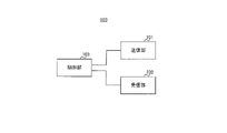
- FIG. 3 is a block diagram showing an example of the configuration of base station 100 according to this embodiment.
- Base station 100 includes, for example, transmitter 101 , receiver 102 , and controller 103 .
- Base station 100 wirelessly communicates with terminal 200 (see FIG. 4).
- the transmission section 101 transmits a downlink (DL) signal to the terminal 200 .
- the transmitter 101 transmits a DL signal under the control of the controller 103 .
- a DL signal may include, for example, a downlink data signal and control information (eg, Downlink Control Information (DCI)). Also, the DL signal may include information (for example, UL grant) indicating scheduling regarding signal transmission of terminal 200 . Also, the DL signal may include higher layer control information (for example, Radio Resource Control control information). Also, the DL signal may include a reference signal.
- DCI Downlink Control Information
- the DL signal may include information (for example, UL grant) indicating scheduling regarding signal transmission of terminal 200 .
- the DL signal may include higher layer control information (for example, Radio Resource Control control information).
- the DL signal may include a reference signal.
- Channels used for transmitting DL signals include, for example, data channels and control channels.
- the data channel may include a PDSCH (Physical Downlink Shared Channel)
- the control channel may include a PDCCH (Physical Downlink Control Channel).
- base station 100 transmits control information to terminal 200 using PDCCH, and transmits downlink data signals using PDSCH.
- reference signals included in DL signals include demodulation reference signals (DMRS), phase tracking reference signals (PTRS), channel state information-reference signals (CSI-RS), sounding reference signals (SRS ), and Positioning Reference Signal (PRS) for position information.
- DMRS demodulation reference signals
- PTRS phase tracking reference signals
- CSI-RS channel state information-reference signals
- SRS sounding reference signals
- PRS Positioning Reference Signal
- reference signals such as DMRS and PTRS are used for demodulation of downlink data signals and transmitted using PDSCH.
- the receiving unit 102 receives an uplink (UL) signal transmitted from the terminal 200.
- the receiving unit 102 receives the UL signal under the control of the control unit 103.
- the control unit 103 controls the communication operation of the base station 100, including the transmission processing of the transmission unit 101 and the reception processing of the reception unit 102.
- control unit 103 acquires information such as data and control information from the upper layer and outputs it to the transmission unit 101 .
- Control section 103 also outputs the data received from receiving section 102, control information, and the like to an upper layer.
- control unit 103 determines that the terminal 200 applies TBoMS
- the control unit 103 controls transmission of control information regarding TBoMS application to the terminal 200 .
- the control section 103 controls reception of the uplink signal to which TBoMS is applied.
- the control unit 103 receives PUSCH signals of a plurality of slots and configures a transport block.
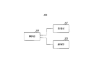
- FIG. 4 is a block diagram showing an example of the configuration of terminal 200 according to this embodiment.
- Terminal 200 includes, for example, receiver 201 , transmitter 202 , and controller 203 .
- the terminal 200 wirelessly communicates with the base station 100, for example.
- the receiving unit 201 receives the DL signal transmitted from the base station 100.
- the receiver 201 receives a DL signal under the control of the controller 203 .
- the transmission unit 202 transmits the UL signal to the base station 100.
- the transmitter 202 transmits UL signals under the control of the controller 203 .
- the UL signal may include, for example, an uplink data signal and control information. For example, information about the processing capability of terminal 200 (eg, UE capability) may be included. Also, the UL signal may include a reference signal.
- Channels used to transmit UL signals include, for example, data channels and control channels.
- the data channel includes PUSCH (Physical Uplink Shared Channel)
- the control channel includes PUCCH (Physical Uplink Control Channel).
- terminal 200 receives control information from base station 100 using PUCCH, and transmits uplink data signals using PUSCH.
- the reference signal included in the UL signal may include at least one of DMRS, PTRS, CSI-RS, SRS, and PRS, for example.
- reference signals such as DMRS and PTRS are used for demodulation of uplink data signals and transmitted using PUSCH.
- the control unit 203 controls communication operations of the terminal 200, including reception processing in the reception unit 201 and transmission processing in the transmission unit 202.
- control unit 203 acquires information such as data and control information from the upper layer and outputs it to the transmission unit 202 . Also, the control unit 203 outputs, for example, the data and control information received from the receiving unit 201 to the upper layer.
- the control unit 203 controls transmission of uplink signals to which TBoMS is applied.
- the control unit 203 may control signal transmission to which TBoMS is applied based on control information acquired from the base station 100 .
- the control unit 203 determines a transport block size (TBS) to be transmitted in TBoMS, and controls transmission of a TB having the determined TBS using PUSCH of a plurality of slots.
- TBS transport block size
- the channels used for DL signal transmission and the channels used for UL signal transmission are not limited to the above examples.
- the channel used for DL signal transmission and the channel used for UL signal transmission may include RACH (Random Access Channel) and PBCH (Physical Broadcast Channel).
- RACH may be used, for example, to transmit Downlink Control Information (DCI) containing Random Access Radio Network Temporary Identifier (RA-RNTI).
- DCI Downlink Control Information
- RA-RNTI Random Access Radio Network Temporary Identifier
- TBS ⁇ Regarding the decision of TBS> Determination of a TBS corresponding to a TB spanning multiple slots will be described below. For example, for determination of TBS, at least one of the following three TBS calculation methods may be applied.
- N RE When calculating the number of REs (N RE ), we expand to the number of REs in multiple slots rather than in one slot.
- N RE (N′ RE ) may be calculated as in Equation (1) below.
- N RB SC indicates the number of subcarriers per resource block
- N sh symb indicates the number of symbols in slot units
- N PRB DMRS indicates the number used for DMRS in slot units.
- N PRB oh indicate the number of overheads.
- each variable may be changed to the number of REs spanning multiple slots.
- N PRB oh in equation (1) may be calculated by either:
- the number of undivided actual repetitions may be multiplied.
- ⁇ (Opt 2-2-2) Multiply the nominal repetition number.
- different parameters set by PDSCH-ServingCellConfig may be used instead of xOverhead.
- N PRB oh may be calculated based on the added parameter and xOverhead, both slot symbol numbers.
- different parameters may be set when TBoMS is applied and when not applied.
- N sh symb N PRB DMRS
- (Opt 1) Multiply the actual repetition number. In this case, the number of undivided actual repetitions may be multiplied.
- ⁇ TBS calculation method 2 Calculate N RE based on SLIV of TDRA, and calculate N info according to TDRA.
- calculation method 2 any of the following methods may be applied.
- ⁇ (Opt 1) Multiply the number of actual repetitions. In this case, the number of actual repetitions without segmentation may be multiplied.
- the actual repetition is the repetition to be finally transmitted, and the nominal repetition may be interpreted as the repetition notified/assigned to the terminal by the base station.
- the following factors can change actual repetition and nominal repetition:
- the nominal repetition may be excluded.
- the nominal repetition may be split at the slot boundary and turned into two actual repetitions.
- ⁇ TBS calculation method 3> Add the given parameters.
- the parameter may be notified using DCI and/or higher layer signaling.
- K a predetermined parameter (K) may be added when calculating the value of N info , as shown in Equation (2) below.
- K may be a value (scaling factor) that multiplies the N info value by K, but is not necessarily limited to this purpose.
- a scaling factor may also be referred to as a scaling value.
- N RE indicates the number of REs
- R indicates the coding rate
- Qm indicates the modulation level
- v indicates the number of MIMO layers.
- the right-hand side of equation (2) indicates that the size of the TB to be transmitted in the PUSCH of one slot is multiplied by the scaling factor K.
- the TBS of the TBoMS transmission is calculated by multiplying the size of the TB to be transmitted in the PUSCH of one slot by the scaling factor K.
- a scaling factor may be added in calculating N info , but the present disclosure is not limited to this.
- a scaling factor may be applied to the number of REs allocated within one slot.
- the number of REs allocated in one slot may be multiplied by K times by a scaling factor.
- a scaling factor may also be applied to the quantized intermediate variables.
- the quantized intermediate variable Ninfo' may be multiplied K times by a scaling factor.
- the scaling factor K may be an integer greater than 1. A method of determining the scaling factor will be described below. Note that determination of the scaling factor may be understood as an example of determination of the TBS.
- the scaling factor may be determined, for example, based on at least one of the following determination methods.
- the scaling factor is determined based on at least one of the number of slots assigned to the TBoMS and the number of slots that can be assigned by the TBoMS.
- the scaling factor is decided based on RRC and/or MAC CE.
- the scaling factor is determined based on DCI.
- the scaling factor is determined based on the notified information and the number of allocated slots.
- decision method 5 the method to be applied among the above decision methods 1 to 4 is set by control information (eg, RRC).
- control information eg, RRC
- terminal capability information eg, UE capability
- determination method 6 terminal capability information (eg, UE capability) regarding the applicability of determination methods 1 to 5 above is notified.
- Determination method 1 Determined from the number of TBoMS slots
- the terminal determines the scaling factor based on at least one of the number of allocated slots for the TBoMS and the number of slots that can be allocated by the TBoMS.
- the scaling factors are determined based on the following method examples 1-1 to 1-4.
- the terminal determines the number designated for the TBoMS allocation slots indicated by each row index in the TDRA list set by RRC as the scaling factor.
- the "number of designated slots for TBoMS assignment" may correspond to "the number of (candidate) slots to which the TBoMS is assigned”.
- the “specified number of allocated slots for TBoMS” may correspond to the number of slots configured (specified) by control information (eg, RRC and/or DCI).
- the number of repetitions (number of repetitions) indicated in the TDRA list may be determined as the number specified for the allocated slots of TBoMS. In other words, the number of repetitions indicated in the TDRA list may be used (or reused) for the number of slots assigned to the TBoMS.
- the terminal may determine which of TBoMS and repetition should be applied to perform signal transmission based on information related to communication control. For example, information related to communication control may be set by at least one of RRC, MAC CE, DCI, and UE capability.
- the terminal may perform scaling using the scaling factor for TBS determination when applying TBoMS. In this case, the terminal does not need to perform scaling using the scaling factor when TBoMS is not applied (for example, when repetition is applied).
- the number of slots to which TBoMS can be allocated is the scaling factor.
- the number of slots that can be assigned to TBoMS is the number of slots that cannot be assigned to TBoMS due to overlap with the number of slots specified for TBoMS assignment (the number of slots set by control information) and other resources. and may be determined based on For example, "the number of slots to which TBoMS can be allocated" is a number equal to or less than the number designated as the allocation slots of TBoMS (the number of slots set by control information).
- the “number of slots to which TBoMS can be allocated” may be the number obtained by subtracting the number of slots that cannot be allocated to TBoMS due to overlapping with other resources, etc. from the number designated as slots to be allocated to TBoMS. For example, if the number of slots allocated for TBoMS is set to be 4 by DCI, and one of the four slots set is designated as DL, the number of slots to which TBoMS can be allocated is , 3.
- TDD-UL-DL-Configcommon For example, TDD-UL-DL-Configcommon, TDD-UL-DL-ConfigurationDedicated, etc.
- the number of slots to which TBoMS can be assigned is determined to be the scaling factor. For example, signals received before DCI may consider RRC, UL CI (Cancel Indication), and dynamic SFI (Slot Format Indication) in DCI format 2-0.
- the scaling factor is determined to be the number of slots to which the TBoMS can be assigned, determined based on signals received prior to the first slot to transmit the TBoMS. For example, signals received before the first slot to transmit TBoMS may consider RRC, UL CI, and dynamic SFI in DCI format 2-0.
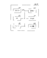
- FIG. 5 as an example, method example 1-3 and method example 1-4 will be described.
- FIG. 5 is a diagram showing an example of determination method 1.
- slot #1 to slot #6 are shown, DCI is transmitted in slot #1, and TBoMS transmission is performed in slots #3 to slot #6.
- the DCI for slot #1 contains information to allocate TBoMS. In other words, DCI in slot #1 allocates TBoMS. Also, in the example of FIG. 5, the first slot for transmitting TBoMS is slot #3.
- the DCI for assigning TBoMS is the DCI for slot #1, so the number of slots to which TBoMS can be assigned is determined based on the signal received before the DCI for slot #1. . The determined number of allocatable slots is then determined to be the scaling factor.
- the slot in which TBoMS is first transmitted is slot #3, so the number of slots to which TBoMS can be assigned is determined based on the signals received before slot #3. The determined number of allocatable slots is then determined to be the scaling factor.
- the number of slots designated for TBoMS allocation or the number of slots to which TBoMS can be allocated is the scaling factor. Not limited. It may be determined that the scaling factor is a value obtained by a predetermined process based on the number of assigned slots for the TBoMS or the number of slots to which the TBoMS can be assigned. For example, the scaling factor may be the number of assigned slots for the TBoMS or the number of slots to which the TBoMS can be assigned divided by X. In this case, X may be set according to a predetermined rule or may be set by RRC.
- scheduling signals for other carriers may be considered.
- a scheduling signal for CA Carrier Aggregation
- Decision method 2 Determined based on RRC and/or MAC CE
- the terminal determines the scaling factor based on RRC settings and/or MAC (Media Access Control) CE (Control element).
- a parameter for setting the scaling factor may be added to the PUSCH-Config IE of RRC.
- the terminal may determine the scaling factor based on parameters added to the RRC PUSCH-Config IE.
- the scaling factor determined based on the RRC settings may be set according to the number of designated slots for TBoMS allocation and/or the number of slots to which TBoMS can be allocated. For example, a scaling factor may be set when the number of slots assigned to the TBoMS is "1" and when the number of slots assigned to the TBoMS is "2".
- a parameter added to the PUSCH-Config IE of RRC may be set according to the number of allocated slots of TBoMS.
- the number assigned to the TBoMS allocation slots may be associated with a scaling factor or a parameter that sets the scaling factor.
- Method 2-2 Decision based on MAC CE
- the MAC CE specified parameter is the scaling factor used to determine the TBS.
- a scaling factor specified in MAC CE may be applied.
- the scaling factor specified by MAC CE may be set according to the number specified for TBoMS allocation slots.
- the MAC CE may specify a scaling factor that is set according to the number of slots assigned to TBoMS.
- the number assigned to the TBoMS allocation slots may be associated with a scaling factor or a parameter that sets the scaling factor.
- the scaling factor set by RRC may be activated or deactivated by MAC CE. In other words, whether to use the scaling factor set by RRC may be set by MAC CE. Alternatively, scaling factor candidates may be configured by RRC, and scaling factors to be applied among the candidates may be configured by MAC CE. In this case, the scaling factor set by RRC and activated or deactivated by MAC CE may be set according to the number of allocated slots of TBoMS.
- the terminal determines the scaling factor based on DCI.
- the scaling factor may be signaled by a field (eg, bit field) storing information included in the DCI.
- the scaling factor may be notified by an FDRA (Frequency Domain Resource Allocation) bit field.
- FDRA Frequency Domain Resource Allocation
- One or more bits of the FDRA field may be used to signal scaling factors.
- the number of RBs for transmitting TBoMS may be limited.
- Bits used for reporting scaling factors may be reserved by limiting RBs.
- Uplink resource allocation type 1 or/and 2 may be applicable.
- the TDRA bit field may signal the scaling factor.
- a scaling factor corresponding to each row index in the TDRA list may be set according to a predetermined rule and/or RRC setting. Then the scaling factor set to the row index specified by the TDRA field may be used.
- a scaling factor may be set in PUSCH-Allocation of the PUSCH-TimeDomainResourceAllocation IE.
- a scaling factor may be set apart from the number specified for the TBoMS allocation slots.
- the scaling factor may be notified based on the MCS (Modulation and Coding Scheme) bit field.
- MCS Modulation and Coding Scheme
- one or more bits of the MCS bit field may indicate the MCS and the remaining one or more bits may indicate the scaling factor.
- the upper one or more bits of the MCS bit field may indicate the MCS, and the remaining lower one or more bits may indicate the scaling factor.
- the lower one or more bits of the MCS bit field may indicate the MCS, and the upper remaining one or more bits may indicate the scaling factor.
- the upper (or lower) 3 bits of the MCS bit field may be used for MCS notification, and the lower (or upper) 2 bits may be used for scaling factor notification.
- the scaling factor is notified based on the MCS bit field, the MCS that can be selected in TBoMS transmission may be restricted. Bits used for signaling the scaling factor may be reserved by limiting the selectable MCS.
- an MCS index with a low index may be selectable in a default MCS table that shows the relationship between multiple MCSs and indexes associated with each MCS.
- the MCS index with a high index may be restricted. For example, if 3 bits are used for MCS notification, 8 MCS indices with low indices may be selectable.
- a low MCS index for example, low spectral efficiency
- a high MCS index eg, high spectral efficiency
- a low MCS index eg, low spectral efficiency
- the MCS index with a low index or the MCS index with a high index is not limited to being selectable.
- selectable MCS indexes and restrictive MCS indexes may be arranged randomly, or selectable MCS indexes or restrictive MCS indexes may be arranged at regular intervals (for example, alternately).
- the selectable MCS index and the limiting MCS index may be fixed, statically or dynamically changed.
- the above-mentioned default MCS table may be regarded as an MCS table used when no scaling factor is notified, or as an MCS table used when TBoMS transmission is not performed, for example.
- the default MCS table is not limited to an example in which selectable MCS indexes and restricted MCS indexes are set.
- an MCS table for TBoMS transmission may be set, and the MCS table for TBoMS transmission may be referenced in the TBoMS transmission.
- the MCS table when TBoMS transmission is performed may be distinguished from the MCS table when TBoMS is not performed (or when the scaling factor is not notified).
- the scaling factor is notified by the FDRA bit field, TDRA bit field, or MCS bit field of DCI is shown, but in DCI, the scaling factor is notified by a bit field different from these bit fields.
- the scaling factor is notified by one bid field is shown, but the scaling factor may be notified by a plurality of bit fields.
- a scaling factor may be signaled by a combination of bits in each of multiple bit fields.
- the scaling factor is notified by the FDRA bit field, TDRA bit field, or MCS bit field specified in DCI, but the bit field for notifying the scaling factor is specified in DCI. may be
- the scaling factor may be notified by a bit field for notifying the scaling factor (a bit field dedicated to the scaling factor).
- the number of bits and the number of bit fields used for notifying the scaling factors described above are examples, and the present disclosure is not limited thereto.
- the number of bits and the number of bit fields may be fixed, dynamically or statically set. For example, this setting may be performed by higher layer control information.
- Decision method 4 Determined based on the notified information and the number of allocated slots
- the terminal determines the scaling factor based on the notified information and/or the number of allocated slots.
- the terminal may determine the scaling factor by combining the number of slots to be assigned by PUSCH and information set by RRC and/or information notified by DCI.
- the number of slots assigned to PUSCH is not particularly limited.
- the number of slots to allocate for PUSCH may correspond to "the number of slots to which TBoMS can be allocated" indicated by the determination method 1 described above, or to the "number of designated slots for allocation of TBoMS".
- the number of slots allocated for PUSCH corresponds to the number of slots determined by at least one of the examples 1-1 to 1-4 of the determination method 1 described above.
- the information set by RRC is not particularly limited.
- the information set by RRC may correspond to the information indicated in determination method 2 above.
- the information notified by DCI is not particularly limited.
- the information notified by DCI may correspond to the information indicated in determination method 3 described above.
- the scaling factor is determined by adding (or subtracting) the notified information (eg, value) to the number of slots allocated by PUSCH.
- the scaling factor may be determined by dividing (or multiplying) the number of slots to allocate for PUSCH with the signaled information (eg, value).
- scaling factors for example, scaling factor index
- the terminal when information about the scaling factor (e.g., scaling factor index) is notified by the DCI, the terminal refers to Table 1 to determine the scaling reference value (scaling reference value), and the number of slots to allocate for PUSCH and scaling A scaling reference value may be added to determine the scaling factor.
- scaling factor index e.g., scaling factor index
- Determination method 5 RRC setting for scaling factor
- the method applied to determine the scaling factor is set by a predetermined rule and/or RRC.
- the terminal determines a method to be applied among determination methods 1 to 4, and determines a scaling factor using the determined method.
- the method applied to determine the scaling factor may be determined based on the UE capabilities.
- a terminal reports information indicating a determination method supported by the terminal (for example, a determination method usable by the terminal) using UE capability. If the terminal supports determination method 3, the terminal reports information indicating support for determination method 3 by UE capability. Then, the terminal receives notification of the scaling factor based on the determination method 3 and determines the scaling factor. In this case, a terminal that does not support determination method 3 may determine the scaling factor based on determination method 1 or 2.
- a terminal that supports a determination method other than determination method 3 may report information indicating the supported determination method (for example, determination methods 1 and/or 2) using the UE capability.
- the method applied to determine the scaling factor may be determined based on RRC configuration.
- information (eg, parameters) regarding scaling factors may be configured.
- Information (eg, parameters) about the scaling factor may indicate at least one of determination methods 1-3.
- the terminal may identify the determination method to use based on the information about the scaling factor, and determine the scaling factor based on the determined determination method.
- Method Example 5-3 Combination
- the method examples 5-1 and 5-2 described above may be combined.
- a terminal reports information indicating one or more determination methods supported by the terminal using UE capabilities.
- the base station that received the report identifies the determination method to be used from one or more determination methods indicated by the UE capability, and configures RRC based on the determined determination method (e.g., notification of information on the scaling factor). I do.
- the terminal may identify a determination method to use from among one or more determination methods supported by the terminal, and determine the scaling factor based on the determined determination method.
- a terminal may report information about the TBS determination of TBoMS by UE capability.
- the information reported by UE capability may be information indicating the terminal's capability for TBS determination in TBoMS.
- the terminal may report information related to determination methods 1 to 5 described above by UE capability.
- information indicating whether or not the terminal is applicable to at least one of determination methods 1 to 5 described above may be reported by UE capability.
- information indicating whether or not at least one of the examples of each method shown in determination method 1 to determination method 5 described above is applicable may be reported by the UE capability.
- the applicability of each example of determination methods 1 to 5 may be reported, or the applicability of multiple methods (or examples of methods) may be collectively reported. .
- the terminal may report the maximum value of the scaling factor by UE capability.
- the maximum scaling factor value may be the maximum scaling factor value supported by the terminal or the maximum scaling factor value usable by the terminal.
- the terminal may report information about the frequencies supported by the terminal through UE capability.
- the reporting method is not particularly limited.
- the terminal may collectively report whether each frequency is compatible.
- the terminal may report whether or not it is compatible as a terminal.
- the terminal may individually report whether it is compatible with each frequency.
- the terminal may individually report whether or not it can handle FR1 and FR2.
- the terminal may report information indicating that FR1 is capable of supporting and FR2 is not capable of supporting through UE capability.
- the terminal may report whether it can handle each SCS.
- the terminal may report whether or not it supports frequencies different from FR1 and FR2. Also, at least one of FR1 and FR2 may be subdivided, and whether or not the terminal is compatible may be reported for each subdivided. For example, if FR2 is subdivided into sub-labeled frequencies such as FR2-1 and FR2-2, even if the device's compatibility with each subdivided FR2-1 and FR2-2 is reported, good.
- the terminal may report information about the duplexing scheme (for example, TDD and/or FDD) that the terminal supports by UE capability. For example, the terminal may collectively report whether or not it supports each of the duplex modes.
- the duplexing scheme for example, TDD and/or FDD
- the scaling factor used to determine the TBS in TBoMS can be determined to be an appropriate value, so the TB in TBoMS can be determined to have an appropriate size.
- the TB in TBoMS can be determined to be an appropriate size, resource utilization efficiency can be improved.
- the determination of the TBS in the TBoMS transmission described above is not limited to the example applied to the determination of the TBS in one TBoMS transmission.
- it may be applied to TBS determination in repeated transmissions of TBoMS.
- TBoMS and repeated transmission may be combined as a method of transmitting one TB.
- Transmission method 1 For example, the terminal may repeatedly transmit TBoMS. Repeated transmissions of TBoMS may be referred to as "TBoMS with repetitions,” for example.
- FIG. 6 is a diagram showing an example of repeated transmission of TBoMS.
- FIG. 6 shows an example of two repeated transmissions of TBoMS in six slots from slot #1 to slot #6.
- slot #1 to slot #3 in FIG. 6 one TBoMS transmission (single TBoMS) is performed.
- one TBoMS transmission is performed in slot #4 to slot #6.
- a TBoMS block in one slot is indicated as a TBoMS unit.
- TBoMS unit #1 and TBoMS unit #2 indicate different TBoMS transmissions.
- each TBoMS unit #1 of slot #1 to slot #3 may correspond to different information (for example, sequence).
- each TBoMS unit #2 of slot #4 to slot #6 may correspond to different information (for example, sequence).
- a terminal may repeatedly transmit TBoMS using multiple slots. For example, the terminal may determine whether or not to repeatedly transmit TBoMS according to the following conditions.
- RRC setting may be set by parameters of the PUSCH-Config IE, for example.
- application of TBoMS, application of repeated transmission, and application of repeated transmission of TBoMS may each be set (designated) by setting RRC.
- a row index is specified in which both the number of repetitions of the TDRA list and the number of slots assigned to the TBoMS are set. Designation of the row index of the TDRA list is performed by DCI, for example.
- the terminal may decide to repeatedly transmit TBoMS when one of the conditions 1 to 5 described above is satisfied. Alternatively, the terminal may decide to repeatedly transmit TBoMS when two or more of conditions 1 to 5 are satisfied.
- the terminal may perform continuous bit selection in bit selection for repeated transmission of TBoMS. For example, the starting point of bit selection may be determined such that the LDPC-encoded bit sequence is continuously bit-selected.
- the starting position of bit selection in a certain slot #n may be the position of the bit next to the last bit of bit selection in a slot before slot #n in which PUSCH is transmitted.
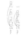
- FIGS. 7A and 7B are diagrams showing an example of bit selection in selection method 1 of transmission method 2.
- FIG. 7A shows bit selection when rate matching is performed on a slot-by-slot basis
- FIG. ) shows an example of bit selection.
- the starting position of bit selection for slot #4 is earlier than slot #4 and is the last position of bit selection in slot #3 where PUSCH is transmitted (TBoMS transmission is performed).
- the position of the bit following the bit is performed.
- the start positions may be determined so that the start positions of bit selection in each repetition transmission (each repetition) are evenly spaced.
- the starting position of the first repetition is determined according to the RV (redundancy version).
- the start positions of repetitions other than the first repetition may be determined based on the sequence length extracted in bit selection of a specific repetition (hereinafter, “specific sequence length”).
- specific sequence length the sequence length extracted in bit selection of a specific repetition
- the bit sequence bit selection start position to be transmitted in the k-th repetition (k is an integer of 2 or more and n or less, n is the number of repetitions, and an integer of 2 or more) is transmitted in the k-1th repetition It may be a position shifted by a specific sequence length from the bit selection start position of the bit sequence. In this case, the bit selection start position is determined at intervals corresponding to a specific sequence length.
- the specific repetition may be the first repetition or the repetition for transmitting the transmission bit sequence with the shortest sequence length.
- the specific repetition in this case may be the repetition of transmitting the transmission bit sequence with the longest sequence length.
- the specific sequence length may be determined based on sequence lengths extracted in each of a plurality of repetition bit selections. For example, it may be the average, maximum, or minimum sequence length extracted in each of bit selections of a plurality of repetitions.
- Transmission method 3 Bit selection method 2 for repeated transmission of TBoMS
- the terminal may apply the id of the RV in each TBoMS transmission occasion based on predetermined rules and/or parameters set by RRC.
- the terminal may apply the RV id in one TBoMS transmission opportunity.
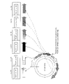
- FIG. 8 is a diagram showing an example of the relationship between RV ids and TBoMS transmission opportunities.
- FIG. 8 shows an example of each relationship from Option 1 (Opt 1) to Option 4 (Opt 4). Note that examples of the relationship between RV ids and TBoMS transmission opportunities are not limited to these. For example, when Opt 1 in FIG. 8 is applied, each RV id of TBoMS follows in order of 0, 2, 3, 1, 0, 2, .
- FIG. 9 shows an example in which each RV id of TBoMS is 0 and 2.
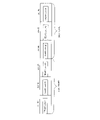
- FIGS. 9A and 9B are diagrams showing examples of bit selection in transmission method 3.
- FIG. Similar to FIGS. 7A and 7B, FIGS. 9A and 9B show an example of two repeated TBoMS transmissions performed in slot #1 to slot #6.
- 9A and 9B show the relationship between the bits transmitted in each slot and the bit positions in the circular buffer. Note that the circular buffer may store a bit sequence corresponding to one TB.
- FIG. 9A shows bit selection when rate matching is performed on a slot-by-slot basis
- FIG. 9B shows an example of bit selection.
- Transmission method 4 RRC setting regarding rate matching in repeated transmission of TBoMS
- the terminal may determine a method of determining the id of the RV in each transmission occasion of TBoMS based on predetermined rules and/or parameters set by RRC.
- the terminal determines which of transmission method 2 and transmission method 3 regarding repeated transmission of TBoMS is to be applied.
- the RV id determination method may be determined based on the UE capability. For example, if the terminal supports bit selection indicated by transmission method 2 (eg, continuous bit selection over repetition), the terminal may report information indicating support for bit selection indicated by transmission method 2 using the UE capability. The terminal may then determine the id of the RV based on the bit selection shown in transmission method 2. If the terminal does not support the bit selection shown in transmission method 2, the terminal may apply the bit selection shown in transmission method 3.
- bit selection indicated by transmission method 2 eg, continuous bit selection over repetition
- Example 4-2 of how to determine the transmission method Determined according to RRC settings
- how the RV id is determined may be determined based on the RRC configuration.
- information (eg, parameters) regarding how to determine the id of the RV may be set.
- the information (for example, parameters) on how to determine the id of the RV may indicate at least one of the bit selection shown in transmission method 2 and the method shown in transmission method 3 described above.
- the terminal may identify the method to use based on information about how to determine the id of the RV, and determine the id of the RV based on the identified method.
- the method shown in transmission method 3 is applied, and if the id of the RV is not set by RRC, the method shown in transmission method 2 Bit selection may be applied.
- Example 4-3 of transmission method determination method combination
- Examples 4-1 and 4-2 described above may be combined.
- the terminal reports one or more determination methods supported by the terminal through the UE capability.
- the base station that received the report identifies the determination method to be used from among one or more determination methods indicated in the UE capability, and performs RRC settings based on the determined determination method (for example, regarding the RV id determination method information).
- the terminal may identify the determination method to be used from among one or more determination methods supported by the terminal, and determine the id of the RV based on the determined determination method.
- a terminal may report information about repeated transmission of TBoMS by UE capability.
- the information reported by UE capability may be information indicating the terminal's capability for repeated transmission of TBoMS.
- the terminal may report information related to transmission methods 1 to 5 of the TBoMS repeated transmission described above by UE capability.
- the following information may be reported by the UE capability.
- information indicating whether or not a terminal is applicable to at least one of transmission methods 1 to 4 of repeated TBoMS transmission described above may be reported by UE capability.
- information indicating whether or not at least one of the examples of each method shown in TBoMS repeated transmission transmission method 1 to transmission method 4 described above is applicable may be reported by the UE capability.
- the applicability of each example of TBoMS repeated transmission transmission methods 1 to 4 may be reported, or the applicability of a plurality of methods (or examples of methods) may be summarized, may be reported.
- the terminal may report the maximum number of slots to which TBoMS is allocated by the UE capability.
- the maximum number of slots to allocate TBoMS may be the maximum number of slots to allocate TBoMS supported by the terminal, or the maximum number of slots to allocate TBoMS that the terminal can use.
- the terminal may report the maximum total number of slots allocated in repeated transmission of TBoMS by UE capability.
- the maximum total number of slots allocated in repeated transmission of TBoMS may be the maximum total number of slots allocated in repeated transmission of TBoMS supported by the terminal, or the maximum number of slots allocated in repeated transmission of TBoMS supported by the terminal. It may be the maximum total number of slots allocated in repeated transmissions.
- the terminal may report the maximum number of repeated transmissions by UE capability.
- the maximum number of repeat transmissions may be the maximum number of repeat transmissions supported by the terminal, or the maximum number of repeat transmissions available to the terminal.
- the terminal may report information about the frequencies supported by the terminal through UE capability.
- the reporting method is not particularly limited.
- the terminal may collectively report whether each frequency is compatible.
- the terminal may report whether or not it is compatible as a terminal.
- the terminal may individually report whether it is compatible with each frequency.
- the terminal may individually report whether or not it can handle FR1 and FR2.
- the terminal may report information indicating that FR1 is capable of supporting and FR2 is not capable of supporting through UE capability.
- the terminal may report whether it can handle each SCS.
- the terminal may report whether or not it supports frequencies different from FR1 and FR2. Also, at least one of FR1 and FR2 may be subdivided, and whether or not the terminal is compatible may be reported for each subdivided. For example, if FR2 is subdivided into sub-labeled frequencies such as FR2-1 and FR2-2, even if the device's compatibility with each subdivided FR2-1 and FR2-2 is reported, good.
- the terminal may report information about the duplexing scheme (for example, TDD and/or FDD) that the terminal supports by UE capability. For example, the terminal may collectively report whether or not it supports each of the duplex modes.
- the duplexing scheme for example, TDD and/or FDD
- TBoMS can be repeatedly transmitted, so the data transmission efficiency can be improved.
- coverage can be extended efficiently.
- the number of slots assigned to TBoMS and repetition transmission may be controlled. For example, in environments where the gain provided by TBoMS is relatively large (eg, when the desired data rate is relatively low), the number of iterations may be decreased and the number of assigned slots for TBoMS increased. Also, for example, in an environment where the gain obtained by repeated transmission is relatively large (for example, when the desired data rate is relatively high), the number of repetitions is increased and the number of allocated slots for TBoMS is decreased. good. Through such control, the respective gains of TBoMS and repeated transmission can be obtained efficiently. It should be noted that the adjustment of the number of allocated slots for TBoMS and the number of repetitions may be performed by the base station.
- TBoMS may be applied in transmission on a channel different from PUSCH.
- TBoMS may be applied to a combination of multiple channels.
- repeated transmission of TBoMS similarly, repeated transmission of TBoMS may be applied to transmission on a channel different from PUSCH, or repeated transmission of TBoMS may be applied to transmission on a channel different from PUSCH for a combination of a plurality of channels. may be applied.
- TBoMS may be applied to downlink signals, or repeated transmission of TBoMS may be applied.
- slot indicates an example of the time unit of radio resources, but the present disclosure is not limited to this.
- Slot may be read as terms such as “minislot”, “frame”, “subframe”, “interval”, or "TTI”.
- transport block indicates an example of a block unit of information, but the present disclosure is not limited to this.
- Transport block is interchanged with other terms such as "information block”, “packet”, “codeword”, “code block”, “sequence”, “encoded sequence”, or “subsequence”. good too.
- each functional block may be implemented using one device that is physically or logically coupled, or directly or indirectly using two or more devices that are physically or logically separated (e.g. , wired, wireless, etc.) and may be implemented using these multiple devices.
- a functional block may be implemented by combining software in the one device or the plurality of devices.
- Functions include judging, determining, determining, calculating, calculating, processing, deriving, examining, searching, checking, receiving, transmitting, outputting, accessing, resolving, selecting, choosing, establishing, comparing, assuming, expecting, assuming, Broadcasting, notifying, communicating, forwarding, configuring, reconfiguring, allocating, mapping, assigning, etc.
- a functional block (component) that makes transmission work is called a transmitting unit or transmitter.
- the implementation method is not particularly limited.
- a base station, a terminal, etc. may function as a computer that performs processing of the wireless communication method of the present disclosure.
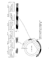
- FIG. 10 is a diagram illustrating an example of hardware configurations of a base station and terminals according to an embodiment of the present disclosure.
- the base station 100 and terminal 200 described above may be physically configured as a computer device including a processor 1001, a memory 1002, a storage 1003, a communication device 1004, an input device 1005, an output device 1006, a bus 1007, and the like.
- base station 100 and terminal 200 can be read as a circuit, device, unit, or the like.
- the hardware configuration of base station 100 and terminal 200 may be configured to include one or more of each device shown in the figure, or may be configured without some devices.
- Each function of the base station 100 and the terminal 200 is implemented by loading predetermined software (programs) onto hardware such as the processor 1001 and memory 1002 so that the processor 1001 performs calculations and controls communication by the communication device 1004. , and controlling at least one of reading and writing of data in the memory 1002 and the storage 1003 .
- the processor 1001 for example, operates an operating system and controls the entire computer.
- the processor 1001 may be configured by a central processing unit (CPU) including an interface with peripheral devices, a control device, an arithmetic device, registers, and the like.
- CPU central processing unit
- the control unit 103 and the control unit 203 described above may be implemented by the processor 1001 .
- the processor 1001 reads programs (program codes), software modules, data, etc. from at least one of the storage 1003 and the communication device 1004 to the memory 1002, and executes various processes according to them.
- programs program codes
- software modules software modules
- data etc.
- the program a program that causes a computer to execute at least part of the operations described in the above embodiments is used.
- the control unit 103 of the base station 100 or the control unit 203 of the terminal 200 may be implemented by a control program stored in the memory 1002 and operating in the processor 1001, and other functional blocks may be implemented in the same way. good.
- FIG. Processor 1001 may be implemented by one or more chips.
- the program may be transmitted from a network via an electric communication line.
- the memory 1002 is a computer-readable recording medium, and is composed of at least one of, for example, ROM (Read Only Memory), EPROM (Erasable Programmable ROM), EEPROM (Electrically Erasable Programmable ROM), RAM (Random Access Memory), etc. may be
- ROM Read Only Memory
- EPROM Erasable Programmable ROM
- EEPROM Electrical Erasable Programmable ROM
- RAM Random Access Memory
- the memory 1002 may also be called a register, cache, main memory (main storage device), or the like.
- the memory 1002 can store executable programs (program code), software modules, etc. for implementing a wireless communication method according to an embodiment of the present disclosure.
- the storage 1003 is a computer-readable recording medium, for example, an optical disc such as a CD-ROM (Compact Disc ROM), a hard disk drive, a flexible disc, a magneto-optical disc (for example, a compact disc, a digital versatile disc, a Blu-ray disk), smart card, flash memory (eg, card, stick, key drive), floppy disk, magnetic strip, and/or the like.
- Storage 1003 may also be called an auxiliary storage device.
- the storage medium described above may be, for example, a database, server, or other suitable medium including at least one of memory 1002 and storage 1003 .
- the communication device 1004 is hardware (transmitting/receiving device) for communicating between computers via at least one of a wired network and a wireless network, and is also called a network device, a network controller, a network card, a communication module, or the like.
- the communication device 1004 includes a high-frequency switch, a duplexer, a filter, a frequency synthesizer, etc., in order to realize at least one of, for example, frequency division duplex (FDD) and time division duplex (TDD). may consist of For example, the transmitting unit 101, the receiving unit 102, the receiving unit 201, the transmitting unit 202, etc. described above may be realized by the communication device 1004.
- the input device 1005 is an input device (for example, keyboard, mouse, microphone, switch, button, sensor, etc.) that receives input from the outside.
- the output device 1006 is an output device (eg, display, speaker, LED lamp, etc.) that outputs to the outside. Note that the input device 1005 and the output device 1006 may be integrated (for example, a touch panel).
- Each device such as the processor 1001 and the memory 1002 is connected by a bus 1007 for communicating information.
- the bus 1007 may be configured using a single bus, or may be configured using different buses between devices.
- the base station 100 and the terminal 200 include hardware such as microprocessors, digital signal processors (DSPs), ASICs (Application Specific Integrated Circuits), PLDs (Programmable Logic Devices), and FPGAs (Field Programmable Gate Arrays). , and part or all of each functional block may be implemented by the hardware.
- processor 1001 may be implemented using at least one of these pieces of hardware.
- notification of information includes physical layer signaling (e.g., DCI (Downlink Control Information), UCI (Uplink Control Information)), higher layer signaling (e.g., RRC (Radio Resource Control) signaling, MAC (Medium Access Control) signaling, It may be implemented by broadcast information (MIB (Master Information Block), SIB (System Information Block)), other signals, or a combination thereof.
- RRC signaling may also be called an RRC message, and may be, for example, an RRC connection setup message, an RRC connection reconfiguration message, or the like.
- Each aspect/embodiment described in the present disclosure includes LTE (Long Term Evolution), LTE-A (LTE-Advanced), SUPER 3G, IMT-Advanced, 4G (4th generation mobile communication system), 5G (5th generation mobile communication system), FRA (Future Radio Access), NR (New Radio), W-CDMA (registered trademark), GSM (registered trademark), CDMA2000, UMB (Ultra Mobile Broadband), IEEE 802.11 (Wi-Fi (registered trademark) )), IEEE 802.16 (WiMAX®), IEEE 802.20, UWB (Ultra-WideBand), Bluetooth®, and other suitable systems and extended It may be applied to at least one of the next generation systems. Also, a plurality of systems may be applied in combination (for example, a combination of at least one of LTE and LTE-A and 5G, etc.).
- Base station operation Certain operations that are described in this disclosure as being performed by a base station may also be performed by its upper node in some cases.
- various operations performed for communication with a terminal may be performed by the base station and other network nodes other than the base station (e.g. MME or S-GW, etc. (including but not limited to).
- MME or S-GW network nodes other than the base station
- the case where there is one network node other than the base station is exemplified above, it may be a combination of a plurality of other network nodes (for example, MME and S-GW).
- (input/output direction) Information and the like can be output from the upper layer (or lower layer) to the lower layer (or higher layer). It may be input and output via multiple network nodes.
- Input/output information and the like may be stored in a specific location (for example, memory), or may be managed using a management table. Input/output information and the like can be overwritten, updated, or appended. The output information and the like may be deleted. The entered information and the like may be transmitted to another device.
- the determination may be made by a value represented by one bit (0 or 1), by a true/false value (Boolean: true or false), or by numerical comparison (for example, a predetermined value).
- Software whether referred to as software, firmware, middleware, microcode, hardware description language or otherwise, includes instructions, instruction sets, code, code segments, program code, programs, subprograms, and software modules. , applications, software applications, software packages, routines, subroutines, objects, executables, threads of execution, procedures, functions, and the like.
- software, instructions, information, etc. may be transmitted and received via a transmission medium.
- the software uses at least one of wired technology (coaxial cable, fiber optic cable, twisted pair, digital subscriber line (DSL), etc.) and wireless technology (infrared, microwave, etc.) to website, Wired and/or wireless technologies are included within the definition of transmission medium when sent from a server or other remote source.
- wired technology coaxial cable, fiber optic cable, twisted pair, digital subscriber line (DSL), etc.
- wireless technology infrared, microwave, etc.
- Information, signal Information, signals, etc. described in this disclosure may be represented using any of a variety of different technologies.
- data, instructions, commands, information, signals, bits, symbols, chips, etc. may refer to voltages, currents, electromagnetic waves, magnetic fields or magnetic particles, light fields or photons, or any of these. may be represented by a combination of
- the channel and/or symbols may be signaling.
- a signal may also be a message.
- a component carrier may also be called a carrier frequency, a cell, a frequency carrier, or the like.
- system As used in this disclosure, the terms “system” and “network” are used interchangeably.
- radio resources may be indexed.
- Base station wireless base station
- base station radio base station
- radio base station fixed station
- NodeB nodeB
- eNodeB eNodeB
- gNodeB gNodeB
- a base station may also be referred to by terms such as macrocell, small cell, femtocell, picocell, and the like.
- a base station can accommodate one or more (eg, three) cells.
- the overall coverage area of the base station can be partitioned into multiple smaller areas, each smaller area being associated with a base station subsystem (e.g., an indoor small base station (RRH: Communication services can also be provided by Remote Radio Head)).
- RRH indoor small base station
- the terms "cell” or “sector” refer to part or all of the coverage area of at least one of the base stations and base station subsystems that serve communication within such coverage.
- terminal In this disclosure, terms such as “Mobile Station (MS),” “user terminal,” “User Equipment (UE),” “terminal,” etc. may be used interchangeably. .
- a mobile station is defined by those skilled in the art as a subscriber station, mobile unit, subscriber unit, wireless unit, remote unit, mobile device, wireless device, wireless communication device, remote device, mobile subscriber station, access terminal, mobile terminal, wireless It may also be called a terminal, remote terminal, handset, user agent, mobile client, client, or some other suitable term.
- At least one of a base station and a mobile station may be called a transmitter, a receiver, a communication device, and the like. At least one of the base station and the mobile station may be a device mounted on a mobile object, the mobile object itself, or the like.
- the mobile object may be a vehicle (e.g., car, airplane, etc.), an unmanned mobile object (e.g., drone, self-driving car, etc.), or a robot (manned or unmanned ).
- at least one of the base station and the mobile station includes devices that do not necessarily move during communication operations.
- at least one of the base station and the mobile station may be an IoT (Internet of Things) device such as a sensor.
- IoT Internet of Things
- the base station in the present disclosure may be read as a user terminal.
- communication between a base station and a user terminal is replaced with communication between multiple user terminals (for example, D2D (Device-to-Device), V2X (Vehicle-to-Everything), etc.)
- terminal 200 may have the functions of base station 100 described above.
- words such as "up” and “down” may be replaced with words corresponding to inter-terminal communication (for example, "side”).
- uplink channels, downlink channels, etc. may be read as side channels.
- a terminal in the present disclosure may be read as a base station.
- the base station 100 may have the functions that the terminal 200 described above has.
- determining may encompass a wide variety of actions.
- “Judgement”, “determining” are, for example, judging, calculating, computing, processing, deriving, investigating, looking up, searching, inquiring (eg, lookup in a table, database, or other data structure), ascertaining as “judged” or “determined”, and the like.
- "judgment” and “determination” are used for receiving (e.g., receiving information), transmitting (e.g., transmitting information), input, output, access (accessing) (for example, accessing data in memory) may include deeming that a "judgment” or “decision” has been made.
- judgment and “decision” are considered to be “judgment” and “decision” by resolving, selecting, choosing, establishing, comparing, etc. can contain.
- judgment and “decision” may include considering that some action is “judgment” and “decision”.
- judgment (decision) may be read as “assuming”, “expecting”, “considering”, or the like.
- connection means any direct or indirect connection or coupling between two or more elements, It can include the presence of one or more intermediate elements between two elements being “connected” or “coupled.” Couplings or connections between elements may be physical, logical, or a combination thereof. For example, “connection” may be read as "access”.
- two elements are defined using at least one of one or more wires, cables, and printed electrical connections and, as some non-limiting and non-exhaustive examples, in the radio frequency domain. , electromagnetic energy having wavelengths in the microwave and optical (both visible and invisible) regions, and the like.
- the reference signal may be abbreviated as RS (Reference Signal), or may be referred to as Pilot according to the applicable standard.
- a radio frame may consist of one or more frames in the time domain. Each frame or frames in the time domain may be referred to as a subframe. A subframe may also consist of one or more slots in the time domain. A subframe may be a fixed time length (eg, 1 ms) independent of numerology.
- a numerology may be a communication parameter that applies to the transmission and/or reception of a signal or channel. Numerology, for example, subcarrier spacing (SCS), bandwidth, symbol length, cyclic prefix length, transmission time interval (TTI), number of symbols per TTI, radio frame configuration, transmission and reception specific filtering operations performed by the receiver in the frequency domain, specific windowing operations performed by the transceiver in the time domain, and/or the like.
- SCS subcarrier spacing
- TTI transmission time interval
- radio frame configuration for example, transmission and reception specific filtering operations performed by the receiver in the frequency domain, specific windowing operations performed by the transceiver in the time domain, and/or the like.
- a slot may consist of one or more symbols (OFDM (Orthogonal Frequency Division Multiplexing) symbol, SC-FDMA (Single Carrier Frequency Division Multiple Access) symbol, etc.) in the time domain.
- a slot may be a unit of time based on numerology.
- a slot may contain multiple mini-slots. Each minislot may consist of one or more symbols in the time domain. A minislot may also be referred to as a subslot. A minislot may consist of fewer symbols than a slot.
- PDSCH (or PUSCH) transmitted in time units larger than minislots may be referred to as PDSCH (or PUSCH) mapping type A.
- PDSCH (or PUSCH) transmitted using minislots may be referred to as PDSCH (or PUSCH) mapping type B.
- Radio frames, subframes, slots, minislots and symbols all represent time units when transmitting signals. Radio frames, subframes, slots, minislots and symbols may be referred to by other corresponding designations.
- one subframe may be called a Transmission Time Interval (TTI)
- TTI Transmission Time Interval
- TTI Transmission Time Interval
- TTI Transmission Time Interval
- one slot or one minislot may be called a TTI.
- TTI Transmission Time Interval
- at least one of the subframe and TTI may be a subframe (1 ms) in existing LTE, a period shorter than 1 ms (eg, 1-13 symbols), or a period longer than 1 ms may be Note that the unit representing the TTI may be called a slot, mini-slot, or the like instead of a subframe.
- TTI refers to, for example, the minimum scheduling time unit in wireless communication.
- a base station performs scheduling to allocate radio resources (frequency bandwidth, transmission power, etc. that can be used by each user terminal) to each user terminal on a TTI basis.
- radio resources frequency bandwidth, transmission power, etc. that can be used by each user terminal
- a TTI may be a transmission time unit such as a channel-encoded data packet (transport block), code block, or codeword, or may be a processing unit such as scheduling and link adaptation. Note that when a TTI is given, the time interval (for example, the number of symbols) in which transport blocks, code blocks, codewords, etc. are actually mapped may be shorter than the TTI.
- one or more TTIs may be the minimum scheduling time unit. Also, the number of slots (the number of mini-slots) constituting the minimum time unit of the scheduling may be controlled.
- a TTI having a time length of 1 ms may be called a normal TTI (TTI in LTE Rel. 8-12), normal TTI, long TTI, normal subframe, normal subframe, long subframe, slot, or the like.
- a TTI that is shorter than a normal TTI may be called a shortened TTI, a short TTI, a partial or fractional TTI, a shortened subframe, a short subframe, a minislot, a subslot, a slot, and the like.
- the long TTI (e.g., normal TTI, subframe, etc.) may be replaced with a TTI having a time length exceeding 1 ms
- the short TTI e.g., shortened TTI, etc.
- a TTI having the above TTI length may be read instead.
- a resource block is a resource allocation unit in the time domain and the frequency domain, and may include one or more consecutive subcarriers in the frequency domain.
- the number of subcarriers included in the RB may be the same regardless of the neumerology, eg twelve.
- the number of subcarriers included in an RB may be determined based on neumerology.
- the time domain of an RB may include one or more symbols and may be 1 slot, 1 minislot, 1 subframe, or 1 TTI long.
- One TTI, one subframe, etc. may each consist of one or more resource blocks.
- One or more RBs are physical resource blocks (PRBs), sub-carrier groups (SCGs), resource element groups (REGs), PRB pairs, RB pairs, etc. may be called.
- PRBs physical resource blocks
- SCGs sub-carrier groups
- REGs resource element groups
- PRB pairs RB pairs, etc. may be called.
- a resource block may be composed of one or more resource elements (RE: Resource Element).
- RE Resource Element
- 1 RE may be a radio resource region of 1 subcarrier and 1 symbol.
- a bandwidth part (which may also be called a bandwidth part) represents a subset of contiguous common resource blocks (RBs) for a certain numerology in a certain carrier. good.
- the common RB may be identified by an RB index based on the common reference point of the carrier.
- PRBs may be defined in a BWP and numbered within that BWP.
- the BWP may include a BWP for UL (UL BWP) and a BWP for DL (DL BWP).
- UL BWP UL BWP
- DL BWP DL BWP
- One or multiple BWPs may be configured for a UE within one carrier.
- At least one of the configured BWPs may be active, and the UE may not expect to transmit or receive a given signal/channel outside the active BWP.
- BWP bitmap
- radio frames, subframes, slots, minislots and symbols described above are only examples.
- the number of subframes contained in a radio frame the number of slots per subframe or radio frame, the number of minislots contained within a slot, the number of symbols and RBs contained in a slot or minislot, the number of Configurations such as the number of subcarriers, the number of symbols in a TTI, the symbol length, the cyclic prefix (CP) length, etc.
- CP cyclic prefix
- a and B are different may mean “A and B are different from each other.”
- the term may also mean that "A and B are different from C”.
- Terms such as “separate,” “coupled,” etc. may also be interpreted in the same manner as “different.”
- notification of predetermined information is not limited to being performed explicitly, but may be performed implicitly (for example, not notifying the predetermined information). good too.
- One aspect of the present disclosure is useful for mobile communication systems.
Abstract
Description
例えば、3GPP Release-17では、NRにおけるカバレッジ拡張(CE: Coverage Enhancement)について検討することが合意されている(非特許文献1)。 <Knowledge leading to this disclosure>
For example, in 3GPP Release-17, it is agreed to study coverage enhancement (CE: Coverage Enhancement) in NR (Non-Patent Document 1).
・符号系列が長くなることによって、チャネルコーディングのゲインが向上する。
・複数TBを送信する場合に比べて上位レイヤのヘッダー量を削減できる。 - Since resources are allocated across multiple slots, the coding rate (code rate) decreases.
• The gain of channel coding is improved by lengthening the code sequence.
・Compared to the case of transmitting multiple TB, the amount of upper layer headers can be reduced.
図2は、実施の形態に係る無線通信システム10の一例を示した図である。無線通信システム10は、New Radio(NR)に従った無線通信システムであってよい。無線通信システム10は、Next Generation-Radio Access Network20(以下、NG-RAN20)、及び、端末200を含む。 <Example of wireless communication system>
FIG. 2 is a diagram showing an example of the
・FR1:410MHz~7.125GHz
・FR2:24.25GHz~52.6GHz The
・FR1: 410MHz to 7.125GHz
・FR2: 24.25GHz to 52.6GHz
図3は、本実施の形態に係る基地局100の構成の一例を示すブロック図である。基地局100は、例えば、送信部101と、受信部102と、制御部103と、を含む。基地局100は、端末200(図4参照)と無線によって通信する。 <Configuration of base station>
FIG. 3 is a block diagram showing an example of the configuration of
図4は、本実施の形態に係る端末200の構成の一例を示すブロック図である。端末200は、例えば、受信部201と、送信部202と、制御部203と、を含む。端末200は、例えば、基地局100と無線によって通信する。 <Device configuration>
FIG. 4 is a block diagram showing an example of the configuration of
以下では、複数スロットに跨がるTBに対応したTBSの決定について説明する。例えば、TBSの決定について、以下の3つのTBS算出方法の何れか少なくとも1つが適用されてよい。 <Regarding the decision of TBS>
Determination of a TBS corresponding to a TB spanning multiple slots will be described below. For example, for determination of TBS, at least one of the following three TBS calculation methods may be applied.
RE数(NRE)を計算する際、1スロットでなく複数スロットでのRE数に拡張する。
例えば、次の式(1)のように、NRE(N'RE)が計算されてよい。

When calculating the number of REs (N RE ), we expand to the number of REs in multiple slots rather than in one slot.
For example, N RE (N′ RE ) may be calculated as in Equation (1) below.
・(Opt 1-1):PDSCH-ServingCellConfigによって設定したxOverheadを各スロットに割当
・(Opt 1-2):PDSCH-ServingCellConfig で設定したxOverheadをTBoMSが適用されるスロット数で除した値を各スロットにおいてNPRB ohとして設定
この場合、ceilまたはfloorによって商が整数に整えられてもよい。
・(Opt 1-3):新しいパラメータを追加し、TBoMS使用時には、当該パラメータに基づいてNPRB ohに決定
・(Opt 1-4):新しいパラメータを追加し、TBoMS使用時には、当該パラメータとxOverheadとに基づいてNPRB ohに決定
・(Opt 2): TBoMSが適用されるスロット・シンボル数に基づいてNPRB ohを設定
・(Opt 2-1):リソースが割り当てられるスロット数をxOverheadに乗算(Type A repetition like TDRA)
・(Opt 2-2):繰り返し送信数(繰り返し数)をxOverheadに乗算(Type B repetition like TDRA)
・(Opt 2-2-1):actual repetition数を乗算する。
この場合、分割されていないactual repetitionの数が乗算されてもよい。
・(Opt 2-2-2):nominal repetition数を乗算する。
・(Opt 2-3):TDRAのSLIVと割り当てるシンボル数、割り当てた全シンボル数とxOverheadに応じて計算
例えば、(xOverhead) × (全シンボル数) / (TDRAのSLIVと割り当てるシンボル数)によって計算されてもよい。 ・(Opt 1): Set the same N PRB oh for all slots ・(Opt 1-1): Assign xOverhead set by PDSCH-ServingCellConfig to each slot ・(Opt 1-2): xOverhead set by PDSCH-ServingCellConfig is divided by the number of slots to which TBoMS is applied and set as N PRB oh in each slot. In this case, the quotient may be rounded to an integer by ceil or floor.
・(Opt 1-3): Add a new parameter, and when using TBoMS, determine N PRB oh based on this parameter ・(Opt 1-4): Add a new parameter, and when using TBoMS, this parameter and xOverhead (Opt 2): Set N PRB oh based on the number of slot symbols where TBoMS is applied (Opt 2-1): Multiply xOverhead by the number of slots to which resources are allocated (Type A repetition like TDRA)
・(Opt 2-2): Multiply the number of repeated transmissions (number of repetitions) by xOverhead (Type B repetition like TDRA)
• (Opt 2-2-1): Multiply the number of actual repetitions.
In this case, the number of undivided actual repetitions may be multiplied.
・(Opt 2-2-2): Multiply the nominal repetition number.
・(Opt 2-3): Calculated according to SLIV of TDRA and number of symbols to be allocated, total number of symbols to be allocated and xOverhead For example, calculated by (xOverhead) × (total number of symbols) / (SLIV of TDRA and number of symbols to be allocated) may be
この場合、TDD pattern、SFI、CIを考慮してシンボル(RE)数が計算されてもよい。
・(Alt 2): リソースを割り当てられるスロット数を乗算(Type A repetition like TDRA)
・(Alt 3): 繰り返し数を乗算(Type B repetition like TDRA)
・(Opt 1):actual repetition数を乗算する。
この場合、分割されていないactual repetitionの数が乗算されてもよい。
・(Opt 2):nominal repetition数を乗算する。 (Alt 1): Change to the number of symbols (RE) of all resources to which resources are allocated In this case, the number of symbols (RE) may be calculated in consideration of the TDD pattern, SFI, and CI.
・(Alt 2): Multiply the number of slots allocated for resources (Type A repetition like TDRA)
・(Alt 3): Multiply the number of repetitions (Type B repetition like TDRA)
• (Opt 1): Multiply the actual repetition number.
In this case, the number of undivided actual repetitions may be multiplied.
• (Opt 2): Multiply the nominal repetition number.
TDRAのSLIVに基づいてNREを計算し、TDRAに応じてNinfoを計算する。算出方法2については、以下の方法の何れかが適用されてよい。 <
Calculate N RE based on SLIV of TDRA, and calculate N info according to TDRA. As for
所定のパラメータを追加する。例えば、DCI及び/又は上位レイヤのシグナリングを利用して当該パラメータが通知されてよい。 <
Add the given parameters. For example, the parameter may be notified using DCI and/or higher layer signaling.

例えば、端末は、TBoMSの割当スロットに指定された数、及び、TBoMSが割り当て可能なスロット数の何れか少なくとも1つに基づいて、スケーリングファクタを決定する。例えば、以下の方法の例1-1~例1-4に基づいてスケーリングファクタが決定される。 (Determination method 1: Determined from the number of TBoMS slots)
For example, the terminal determines the scaling factor based on at least one of the number of allocated slots for the TBoMS and the number of slots that can be allocated by the TBoMS. For example, the scaling factors are determined based on the following method examples 1-1 to 1-4.
端末は、RRCによって設定されたTDRA listの各row indexに示される、TBoMSの割当スロットに指定された数を、スケーリングファクタに決定する。なお、「TBoMSの割当スロットに指定された数」は、「TBoMSが割り当てられる(候補の)スロット数」に対応してよい。「TBoMSの割当スロットに指定された数」は、制御情報(例えば、RRC及び/又はDCI)によって設定される(指定される)スロット数に対応してよい。 (Method example 1-1)
The terminal determines the number designated for the TBoMS allocation slots indicated by each row index in the TDRA list set by RRC as the scaling factor. Note that the "number of designated slots for TBoMS assignment" may correspond to "the number of (candidate) slots to which the TBoMS is assigned". The “specified number of allocated slots for TBoMS” may correspond to the number of slots configured (specified) by control information (eg, RRC and/or DCI).
RRC configuration及び/又はTBoMSを割り当てるDCIの情報に基づいて決定した、TBoMSを割当可能なスロット数が、スケーリングファクタである、と決定する。なお、「TBoMSを割当可能なスロット数」は、TBoMSの割当スロットに指定された数(制御情報によって設定されるスロット数)と、他のリソースとの重なりなどによってTBoMSに割り当てることができないスロット数とに基づいて決定されてよい。例えば、「TBoMSを割当可能なスロット数」は、TBoMSの割当スロットに指定された数(制御情報によって設定されるスロット数)以下の数である。「TBoMSを割当可能なスロット数」は、TBoMSの割当スロットに指定された数から、他のリソースとの重なりなどによってTBoMSに割り当てることができないスロット数を差し引いた数であってよい。例えば、DCIによってTBoMSの割当スロットに指定された数が4である、と設定され、設定された4つのスロットのうち、1つのスロットがDLに指定された場合、TBoMSを割当可能なスロット数は、3である。 (Method example 1-2)
It is determined that the number of slots to which TBoMS can be allocated, which is determined based on the RRC configuration and/or DCI information for allocating TBoMS, is the scaling factor. The number of slots that can be assigned to TBoMS is the number of slots that cannot be assigned to TBoMS due to overlap with the number of slots specified for TBoMS assignment (the number of slots set by control information) and other resources. and may be determined based on For example, "the number of slots to which TBoMS can be allocated" is a number equal to or less than the number designated as the allocation slots of TBoMS (the number of slots set by control information). The “number of slots to which TBoMS can be allocated” may be the number obtained by subtracting the number of slots that cannot be allocated to TBoMS due to overlapping with other resources, etc. from the number designated as slots to be allocated to TBoMS. For example, if the number of slots allocated for TBoMS is set to be 4 by DCI, and one of the four slots set is designated as DL, the number of slots to which TBoMS can be allocated is , 3.
TBoMSを割り当てるDCIよりも前に受信した信号に基づいて決定したTBoMSを割当可能なスロット数が、スケーリングファクタである、と決定する。例えば、DCIよりも前に受信した信号は、RRC、UL CI(Cancel Indication)、及び、dynamic SFI(Slot Format Indication) in DCI format 2-0 を考慮してもよい。 (Method example 1-3)
The number of slots to which TBoMS can be assigned, determined based on signals received prior to DCI for assigning TBoMS, is determined to be the scaling factor. For example, signals received before DCI may consider RRC, UL CI (Cancel Indication), and dynamic SFI (Slot Format Indication) in DCI format 2-0.
TBoMSを送信する最初のスロットよりも前に受信した信号に基づいて決定したTBoMSを割当可能なスロット数が、スケーリングファクタである、と決定する。例えば、TBoMSを送信する最初のスロットよりも前に受信した信号は、RRC、UL CI、及び、dynamic SFI in DCI format 2-0 を考慮してもよい。 (Method example 1-4)
The scaling factor is determined to be the number of slots to which the TBoMS can be assigned, determined based on signals received prior to the first slot to transmit the TBoMS. For example, signals received before the first slot to transmit TBoMS may consider RRC, UL CI, and dynamic SFI in DCI format 2-0.
例えば、端末は、RRCの設定、及び/又は、MAC(Media Access Control) CE(Control element)に基づいて、スケーリングファクタを決定する。 (Decision method 2: Determined based on RRC and/or MAC CE)
For example, the terminal determines the scaling factor based on RRC settings and/or MAC (Media Access Control) CE (Control element).
例えば、RRCのPUSCH-Config IEに、スケーリングファクタを設定するパラメータが追加されてよい。端末は、RRCのPUSCH-Config IEに追加されたパタメータに基づいて、スケーリングファクタを決定してよい。なお、この場合、RRCの設定に基づいて決定されるスケーリングファクタは、TBoMSの割当スロットに指定された数及び/又はTBoMSを割当可能なスロット数に応じて設定されてもよい。例えば、TBoMSの割当スロットに指定された数が「1」の場合と、TBoMSの割当スロットに指定された数が「2」の場合とで、それぞれ、スケーリングファクタが設定されてもよい。例えば、RRCのPUSCH-Config IEに追加されるパラメータが、TBoMSの割当スロットに指定された数に応じて設定されてよい。例えば、TBoMSの割当スロットに指定された数と、スケーリングファクタ、又は、スケーリングファクタを設定するパラメータとが、関連付けられてもよい。 (Method example 2-1: Decision based on RRC setting)
For example, a parameter for setting the scaling factor may be added to the PUSCH-Config IE of RRC. The terminal may determine the scaling factor based on parameters added to the RRC PUSCH-Config IE. In this case, the scaling factor determined based on the RRC settings may be set according to the number of designated slots for TBoMS allocation and/or the number of slots to which TBoMS can be allocated. For example, a scaling factor may be set when the number of slots assigned to the TBoMS is "1" and when the number of slots assigned to the TBoMS is "2". For example, a parameter added to the PUSCH-Config IE of RRC may be set according to the number of allocated slots of TBoMS. For example, the number assigned to the TBoMS allocation slots may be associated with a scaling factor or a parameter that sets the scaling factor.
例えば、MAC CEで指定されたパラメータがTBSの決定に用いるスケーリングファクタである、と決定されてよい。別言すると、MAC CEで指定されたスケーリングファクタが適用されてよい。 (Method example 2-2: Decision based on MAC CE)
For example, it may be determined that the MAC CE specified parameter is the scaling factor used to determine the TBS. In other words, a scaling factor specified in MAC CE may be applied.
例えば、端末は、DCIに基づいて、スケーリングファクタを決定する。例えば、スケーリングファクタは、DCIに含まれる情報を格納する領域(例えば、bit field)によって通知されてよい。 (Decision method 3: Determined based on DCI)
For example, the terminal determines the scaling factor based on DCI. For example, the scaling factor may be signaled by a field (eg, bit field) storing information included in the DCI.
例えば、FDRA(Frequency Domain Resource Allocation) bit fieldによって、スケーリングファクタが通知されてよい。FDRA fieldの1つ以上のビットがスケーリングファクタの通知に使用されてよい。この場合、TBoMSを送信する場合のRB数が制限されてもよい。RBが制限されることによってスケーリングファクタの通知に使用するビットが確保されてもよい。また、周波数割当において、Uplink resource allocation type 1 or/and 2 のみ適用可能としてもよい。 (Method example 3-1: Determined based on FDRA bit field)
For example, the scaling factor may be notified by an FDRA (Frequency Domain Resource Allocation) bit field. One or more bits of the FDRA field may be used to signal scaling factors. In this case, the number of RBs for transmitting TBoMS may be limited. Bits used for reporting scaling factors may be reserved by limiting RBs. Also, in frequency allocation, only Uplink
例えば、TDRA bit fieldによって、スケーリングファクタが通知されてよい。所定のルール及び/又はRRCの設定によって、TDRA listの各row indexに対応するスケーリングファクタが設定されてよい。そして、TDRA fieldによって指定されたrow indexに設定されたスケーリングファクタが、使用されてよい。例えば、PUSCH-TimeDomainResourceAllocation IEのPUSCH-Allocationにスケーリングファクタが設定されてもよい。TDRA bit fieldにおいて、TBoMSの割当スロットに指定された数とは別にスケーリングファクタが設定されてもよい。 (Method example 3-2: Determined based on TDRA bit field)
For example, the TDRA bit field may signal the scaling factor. A scaling factor corresponding to each row index in the TDRA list may be set according to a predetermined rule and/or RRC setting. Then the scaling factor set to the row index specified by the TDRA field may be used. For example, a scaling factor may be set in PUSCH-Allocation of the PUSCH-TimeDomainResourceAllocation IE. In the TDRA bit field, a scaling factor may be set apart from the number specified for the TBoMS allocation slots.
例えば、MCS(Modulation and Coding Scheme) bit fieldに基づいて、スケーリングファクタが通知されてよい。例えば、MCS bit fieldの1以上のビットがMCSを示し、残りの1以上のビットがスケーリングファクタを示してもよい。例えば、MCS bit fieldの上位の1以上のビットがMCSを示し、下位の残りの1以上のビットがスケーリングファクタを示してもよい。例えば、MCS bit fieldの下位の1以上のビットがMCSを示し、上位の残りの1以上のビットがスケーリングファクタを示してもよい。例えば, MCS bit fieldの上位の(又は下位の)3bitがMCSの通知に使用され、下位の(又は上位の)2bitがスケーリングファクタの通知に使用されてもよい。 (Method example 3-3: Determined based on MCS bit field)
For example, the scaling factor may be notified based on the MCS (Modulation and Coding Scheme) bit field. For example, one or more bits of the MCS bit field may indicate the MCS and the remaining one or more bits may indicate the scaling factor. For example, the upper one or more bits of the MCS bit field may indicate the MCS, and the remaining lower one or more bits may indicate the scaling factor. For example, the lower one or more bits of the MCS bit field may indicate the MCS, and the upper remaining one or more bits may indicate the scaling factor. For example, the upper (or lower) 3 bits of the MCS bit field may be used for MCS notification, and the lower (or upper) 2 bits may be used for scaling factor notification.
また、上述では、DCIに規定されたFDRA bit field、TDRA bit field、又は、MCS bit fieldによってスケーリングファクタが通知される例を示したが、スケーリングファクタを通知するためのbit fieldが、DCIにおいて規定されてもよい。スケーリングファクタを通知するためのbit field(スケーリングファクタ専用のbit field)によってスケーリングファクタが通知されてもよい。 (Method Example 3-4: Variation)
Also, in the above example, the scaling factor is notified by the FDRA bit field, TDRA bit field, or MCS bit field specified in DCI, but the bit field for notifying the scaling factor is specified in DCI. may be The scaling factor may be notified by a bit field for notifying the scaling factor (a bit field dedicated to the scaling factor).
例えば、端末は、通知された情報及び/又は割当スロット数に基づいて、スケーリングファクタを決定する。 (Decision method 4: Determined based on the notified information and the number of allocated slots)
For example, the terminal determines the scaling factor based on the notified information and/or the number of allocated slots.

例えば、端末は、上述した決定方法1~決定方法4の中で、スケーリングファクタの決定に適用される方法が、所定のルール、及び/又は、RRCによって設定される。決定方法5において、端末は、決定方法1~決定方法4の中で適用される方法を決定し、決定した方法を用いて、スケーリングファクタを決定する。 (Determination method 5: RRC setting for scaling factor)
For example, in the terminal, among the
例えば、スケーリングファクタの決定に適用される方法が、UE capabilityに基づいて決定されてもよい。例えば、端末は、端末がサポートする決定方法(例えば、端末が使用可能な決定方法)を示す情報を、UE capabilityによって報告する。端末は、決定方法3をサポートする場合、決定方法3をサポートすることを示す情報を、UE capabilityによって報告する。そして、端末は、決定方法3に基づくスケーリングファクタの通知をうけて、スケーリングファクタの決定を行う。この場合、決定方法3をサポートしない端末は、決定方法1又は2に基づいて、スケーリングファクタを決定してもよい。なお、決定方法3以外の決定方法をサポートする端末が、サポートする決定方法(例えば、決定方法1及び/または2)を示す情報を、UE capabilityによって報告してもよい。 (Method example 5-1: Determined according to UE capability)
For example, the method applied to determine the scaling factor may be determined based on the UE capabilities. For example, a terminal reports information indicating a determination method supported by the terminal (for example, a determination method usable by the terminal) using UE capability. If the terminal supports
例えば、スケーリングファクタの決定に適用される方法が、RRCの設定に基づいて決定されてもよい。例えば, PUSCH-Config IEにおいて、スケーリングファクタに関する情報(例えば、パラメータ)が設定されてよい。スケーリングファクタに関する情報(例えば、パラメータ)は、決定方法1~3の何れか少なくとも1つを示してよい。例えば、端末は、スケーリングファクタに関する情報に基づいて、使用する決定方法を特定し、特定した決定方法に基づいて、スケーリングファクタを決定してもよい。 (Method example 5-2: Determined according to RRC settings)
For example, the method applied to determine the scaling factor may be determined based on RRC configuration. For example, in the PUSCH-Config IE, information (eg, parameters) regarding scaling factors may be configured. Information (eg, parameters) about the scaling factor may indicate at least one of determination methods 1-3. For example, the terminal may identify the determination method to use based on the information about the scaling factor, and determine the scaling factor based on the determined determination method.
例えば、上述した方法の例5-1と例5-2とが組み合わされてもよい。例えば、端末は、端末がサポートする1つ以上の決定方法を示す情報を、UE capabilityによって報告する。報告を受けた基地局は、UE capabilityに示される1つ以上の決定方法の中から、使用する決定方法を特定し、特定した決定方法に基づくRRCの設定(例えば、スケーリングファクタに関する情報の通知)を行う。端末は、RRCの設定に基づいて、端末がサポートする1つ以上の決定方法の中から、使用する決定方法を特定し、特定した決定方法に基づいて、スケーリングファクタを決定してもよい。 (Method Example 5-3: Combination)
For example, the method examples 5-1 and 5-2 described above may be combined. For example, a terminal reports information indicating one or more determination methods supported by the terminal using UE capabilities. The base station that received the report identifies the determination method to be used from one or more determination methods indicated by the UE capability, and configures RRC based on the determined determination method (e.g., notification of information on the scaling factor). I do. Based on the RRC configuration, the terminal may identify a determination method to use from among one or more determination methods supported by the terminal, and determine the scaling factor based on the determined determination method.
端末は、TBoMSのTBSの決定に関する情報を、UE capabilityによって報告してもよい。例えば、UE capabilityによって報告される情報は、TBoMSのTBSの決定に関する端末の能力を示す情報であってよい。 (Determination method 6: Notification of UE capability)
A terminal may report information about the TBS determination of TBoMS by UE capability. For example, the information reported by UE capability may be information indicating the terminal's capability for TBS determination in TBoMS.
例えば、端末は、TBoMSを繰り返し送信してもよい。TBoMSの繰り返し送信は、例えば、「TBoMS with repetitions」と称されてもよい。 (Transmission method 1)
For example, the terminal may repeatedly transmit TBoMS. Repeated transmissions of TBoMS may be referred to as "TBoMS with repetitions," for example.
端末が、TBoMSの繰り返し送信をサポートしている。 (Condition 1)
The terminal supports repeated transmission of TBoMS.
RRCの設定によって、TBoMSの繰り返し送信がenableとされている。なお、このRRCの設定は、例えば、PUSCH-Config IEのパラメータによって設定されてよい。例えば、RRCの設定によって、TBoMSの適用、繰り返し送信の適用、及び、TBoMSの繰り返し送信の適用のそれぞれが設定(指定)されてもよい。 (Condition 2)
Repeated transmission of TBoMS is enabled by RRC settings. Note that this RRC setting may be set by parameters of the PUSCH-Config IE, for example. For example, application of TBoMS, application of repeated transmission, and application of repeated transmission of TBoMS may each be set (designated) by setting RRC.
TDRA listの繰り返し数とTBoMSの割当スロットに指定された数とがどちらも設定されているrow indexが指定される。TDRA listのrow indexの指定は、例えば、DCIによって行われる。 (Condition 3)
A row index is specified in which both the number of repetitions of the TDRA list and the number of slots assigned to the TBoMS are set. Designation of the row index of the TDRA list is performed by DCI, for example.
RRCによって繰り返し数が設定されており、TDRA listのTBoMSの割当スロットに指定された数が設定されているrow indexが指定される。TDRA listのrow indexの指定は、例えば、DCIによって行われる。なお、ここで指定されるrow indexには、TDRA listの繰り返し数が設定されていなくてよい。 (Condition 4)
The number of repetitions is set by RRC, and the row index set to the number of slots allocated for TBoMS in the TDRA list is specified. Designation of the row index of the TDRA list is performed by DCI, for example. Note that the number of repetitions of the TDRA list may not be set for the row index specified here.
RRCによって繰り返し数と、TBoMSの割当スロットに指定された数との両方が設定されている。 (Condition 5)
Both the number of repetitions and the number of allocated slots of TBoMS are set by RRC.
端末は、TBoMSの繰り返し送信のビット選択(bit selection)において、連続したビット選択(continuous bit selection)を実行してもよい。例えば、LDPC符号化されたビット系列が連続してビット選択されるように、ビット選択の開始位置(starting point)が決定されてよい。 (Transmission method 2:
The terminal may perform continuous bit selection in bit selection for repeated transmission of TBoMS. For example, the starting point of bit selection may be determined such that the LDPC-encoded bit sequence is continuously bit-selected.
例えば、或るスロット#nにおけるビット選択の開始位置は、PUSCHが送信され、スロット#nよりも前のスロットにおけるビット選択の最後のビットの次のビットの位置であってよい。 (Selection method 1)
For example, the starting position of bit selection in a certain slot #n may be the position of the bit next to the last bit of bit selection in a slot before slot #n in which PUSCH is transmitted.
例えば、各繰り返し送信(各repetition)におけるビット選択の開始位置が、等間隔となるように、開始位置が決定されてよい。 (Selection method 2)
For example, the start positions may be determined so that the start positions of bit selection in each repetition transmission (each repetition) are evenly spaced.
TBoMSの繰り返し送信では、端末は、所定のルール及び/又はRRCによって設定されたパラメータに基づいて、TBoMSの送信機会(transmission occasion)のそれぞれにおけるRVのidを適用してよい。 (Transmission method 3:
In TBoMS repeated transmission, the terminal may apply the id of the RV in each TBoMS transmission occasion based on predetermined rules and/or parameters set by RRC.
TBoMSの繰り返し送信では、端末は、所定のルール及び/又はRRCによって設定されたパラメータに基づいて、TBoMSの送信機会(transmission occasion)のそれぞれにおけるRVのidの決定方法を判断してよい。 (Transmission method 4: RRC setting regarding rate matching in repeated transmission of TBoMS)
In repeated transmission of TBoMS, the terminal may determine a method of determining the id of the RV in each transmission occasion of TBoMS based on predetermined rules and/or parameters set by RRC.
例えば、RVのidの決定方法がUE capabilityに基づいて決定されてよい。例えば、端末は、送信方法2に示すビット選択(例えば、continuous bit selection over repetition)をサポートする場合、送信方法2に示すビット選択をサポートすることを示す情報をUE capabilityによって報告してもよい。そして、端末は、送信方法2に示すビット選択に基づいて、RVのidを決定してよい。なお、端末は、送信方法2に示すビット選択をサポートしない場合は、送信方法3に示すビット選択を適用してもよい。 (Example 4-1 of how to determine the transmission method: Determined according to UE capability)
For example, the RV id determination method may be determined based on the UE capability. For example, if the terminal supports bit selection indicated by transmission method 2 (eg, continuous bit selection over repetition), the terminal may report information indicating support for bit selection indicated by
例えば、RVのidの決定方法が、RRCの設定に基づいて決定されてもよい。例えば, PUSCH-Config IEにおいて、RVのidの決定方法に関する情報(例えば、パラメータ)が設定されてよい。RVのidの決定方法に関する情報(例えば、パラメータ)は、上述した、送信方法2に示すビット選択と、送信方法3に示す方法との少なくとも1つを示してよい。例えば、端末は、RVのidの決定方法に関する情報に基づいて、使用する方法を特定し、特定した方法に基づいて、RVのidを決定してもよい。例えば、送信方法3に示す方法が使用するRVのidがRRCによって設定されている場合、送信方法3に示す方法が適用され、RVのidがRRCによって設定されていない場合、送信方法2に示すビット選択が適用されてよい。 (Example 4-2 of how to determine the transmission method: Determined according to RRC settings)
For example, how the RV id is determined may be determined based on the RRC configuration. For example, in the PUSCH-Config IE, information (eg, parameters) regarding how to determine the id of the RV may be set. The information (for example, parameters) on how to determine the id of the RV may indicate at least one of the bit selection shown in
例えば、上述した例4-1と例4-2とが組み合わされてもよい。例えば、端末は、端末がサポートする1つ以上の決定方法を、UE capabilityによって報告する。報告を受けた基地局は、UE capabilityに示される1つ以上の決定方法の中から、使用する決定方法を特定し、特定した決定方法に基づくRRCの設定(例えば、RVのidの決定方法に関する情報の通知)を行う。端末は、RRCの設定に基づいて、端末がサポートする1つ以上の決定方法の中から、使用する決定方法を特定し、特定した決定方法に基づいて、RVのidを決定してもよい。 (Example 4-3 of transmission method determination method: combination)
For example, Examples 4-1 and 4-2 described above may be combined. For example, the terminal reports one or more determination methods supported by the terminal through the UE capability. The base station that received the report identifies the determination method to be used from among one or more determination methods indicated in the UE capability, and performs RRC settings based on the determined determination method (for example, regarding the RV id determination method information). Based on the RRC configuration, the terminal may identify the determination method to be used from among one or more determination methods supported by the terminal, and determine the id of the RV based on the determined determination method.
端末は、TBoMSの繰り返し送信に関する情報を、UE capabilityによって報告してもよい。例えば、UE capabilityによって報告される情報は、TBoMSの繰り返し送信に関する端末の能力を示す情報であってよい。 (Transmission method 5: Notification of UE capability)
A terminal may report information about repeated transmission of TBoMS by UE capability. For example, the information reported by UE capability may be information indicating the terminal's capability for repeated transmission of TBoMS.
なお、上記実施形態の説明に用いたブロック図は、機能単位のブロックを示している。これらの機能ブロック(構成部)は、ハードウェア及びソフトウェアの少なくとも一方の任意の組み合わせによって実現される。また、各機能ブロックの実現方法は特に限定されない。すなわち、各機能ブロックは、物理的又は論理的に結合した1つの装置を用いて実現されてもよいし、物理的又は論理的に分離した2つ以上の装置を直接的又は間接的に(例えば、有線、無線などを用いて)接続し、これら複数の装置を用いて実現されてもよい。機能ブロックは、上記1つの装置又は上記複数の装置にソフトウェアを組み合わせて実現されてもよい。 (Hardware configuration)
It should be noted that the block diagrams used in the description of the above embodiments show blocks in units of functions. These functional blocks (components) are realized by any combination of at least one of hardware and software. Also, the method of implementing each functional block is not particularly limited. That is, each functional block may be implemented using one device that is physically or logically coupled, or directly or indirectly using two or more devices that are physically or logically separated (e.g. , wired, wireless, etc.) and may be implemented using these multiple devices. A functional block may be implemented by combining software in the one device or the plurality of devices.
情報の通知は、本開示において説明した態様/実施形態に限られず、他の方法を用いて行われてもよい。例えば、情報の通知は、物理レイヤシグナリング(例えば、DCI(Downlink Control Information)、UCI(Uplink Control Information))、上位レイヤシグナリング(例えば、RRC(Radio Resource Control)シグナリング、MAC(Medium Access Control)シグナリング、報知情報(MIB(Master Information Block)、SIB(System Information Block)))、その他の信号又はこれらの組み合わせによって実施されてもよい。また、RRCシグナリングは、RRCメッセージと呼ばれてもよく、例えば、RRC接続セットアップ(RRC Connection Setup)メッセージ、RRC接続再構成(RRC Connection Reconfiguration)メッセージなどであってもよい。 (notification of information, signaling)
Notification of information is not limited to the aspects/embodiments described in this disclosure, and may be performed using other methods. For example, notification of information includes physical layer signaling (e.g., DCI (Downlink Control Information), UCI (Uplink Control Information)), higher layer signaling (e.g., RRC (Radio Resource Control) signaling, MAC (Medium Access Control) signaling, It may be implemented by broadcast information (MIB (Master Information Block), SIB (System Information Block)), other signals, or a combination thereof. RRC signaling may also be called an RRC message, and may be, for example, an RRC connection setup message, an RRC connection reconfiguration message, or the like.
本開示において説明した各態様/実施形態は、LTE(Long Term Evolution)、LTE-A(LTE-Advanced)、SUPER 3G、IMT-Advanced、4G(4th generation mobile communication system)、5G(5th generation mobile communication system)、FRA(Future Radio Access)、NR(New Radio)、W-CDMA(登録商標)、GSM(登録商標)、CDMA2000、UMB(Ultra Mobile Broadband)、IEEE 802.11(Wi-Fi(登録商標))、IEEE 802.16(WiMAX(登録商標))、IEEE 802.20、UWB(Ultra-WideBand)、Bluetooth(登録商標)、その他の適切なシステムを利用するシステム及びこれらに基づいて拡張された次世代システムの少なくとも一つに適用されてもよい。また、複数のシステムが組み合わされて(例えば、LTE及びLTE-Aの少なくとも一方と5Gとの組み合わせ等)適用されてもよい。 (Applicable system)
Each aspect/embodiment described in the present disclosure includes LTE (Long Term Evolution), LTE-A (LTE-Advanced), SUPER 3G, IMT-Advanced, 4G (4th generation mobile communication system), 5G (5th generation mobile communication system), FRA (Future Radio Access), NR (New Radio), W-CDMA (registered trademark), GSM (registered trademark), CDMA2000, UMB (Ultra Mobile Broadband), IEEE 802.11 (Wi-Fi (registered trademark) )), IEEE 802.16 (WiMAX®), IEEE 802.20, UWB (Ultra-WideBand), Bluetooth®, and other suitable systems and extended It may be applied to at least one of the next generation systems. Also, a plurality of systems may be applied in combination (for example, a combination of at least one of LTE and LTE-A and 5G, etc.).
本開示において説明した各態様/実施形態の処理手順、シーケンス、フローチャートなどは、矛盾の無い限り、順序を入れ替えてもよい。例えば、本開示において説明した方法については、例示的な順序を用いて様々なステップの要素を提示しており、提示した特定の順序に限定されない。 (Processing procedure, etc.)
The processing procedures, sequences, flowcharts, etc. of each aspect/embodiment described in this disclosure may be rearranged as long as there is no contradiction. For example, the methods described in this disclosure present elements of the various steps using a sample order, and are not limited to the specific order presented.
本開示において基地局によって行われるとした特定動作は、場合によってはその上位ノード(upper node)によって行われることもある。基地局を有する1つ又は複数のネットワークノード(network nodes)からなるネットワークにおいて、端末との通信のために行われる様々な動作は、基地局及び基地局以外の他のネットワークノード(例えば、MME又はS-GWなどが考えられるが、これらに限られない)の少なくとも1つによって行われ得ることは明らかである。上記において基地局以外の他のネットワークノードが1つである場合を例示したが、複数の他のネットワークノードの組み合わせ(例えば、MME及びS-GW)であってもよい。 (Base station operation)
Certain operations that are described in this disclosure as being performed by a base station may also be performed by its upper node in some cases. In a network consisting of one or more network nodes with a base station, various operations performed for communication with a terminal may be performed by the base station and other network nodes other than the base station (e.g. MME or S-GW, etc. (including but not limited to). Although the case where there is one network node other than the base station is exemplified above, it may be a combination of a plurality of other network nodes (for example, MME and S-GW).
情報等(※「情報、信号」の項目参照)は、上位レイヤ(又は下位レイヤ)から下位レイヤ(又は上位レイヤ)へ出力され得る。複数のネットワークノードを介して入出力されてもよい。 (input/output direction)
Information and the like (*see the item “information, signal”) can be output from the upper layer (or lower layer) to the lower layer (or higher layer). It may be input and output via multiple network nodes.
入出力された情報等は特定の場所(例えば、メモリ)に保存されてもよいし、管理テーブルを用いて管理してもよい。入出力される情報等は、上書き、更新、又は追記され得る。出力された情報等は削除されてもよい。入力された情報等は他の装置へ送信されてもよい。 (Handling of input/output information, etc.)
Input/output information and the like may be stored in a specific location (for example, memory), or may be managed using a management table. Input/output information and the like can be overwritten, updated, or appended. The output information and the like may be deleted. The entered information and the like may be transmitted to another device.
判定は、1ビットで表される値(0か1か)によって行われてもよいし、真偽値(Boolean:true又はfalse)によって行われてもよいし、数値の比較(例えば、所定の値との比較)によって行われてもよい。 (Determination method)
The determination may be made by a value represented by one bit (0 or 1), by a true/false value (Boolean: true or false), or by numerical comparison (for example, a predetermined value).
ソフトウェアは、ソフトウェア、ファームウェア、ミドルウェア、マイクロコード、ハードウェア記述言語と呼ばれるか、他の名称で呼ばれるかを問わず、命令、命令セット、コード、コードセグメント、プログラムコード、プログラム、サブプログラム、ソフトウェアモジュール、アプリケーション、ソフトウェアアプリケーション、ソフトウェアパッケージ、ルーチン、サブルーチン、オブジェクト、実行可能ファイル、実行スレッド、手順、機能などを意味するよう広く解釈されるべきである。 (software)
Software, whether referred to as software, firmware, middleware, microcode, hardware description language or otherwise, includes instructions, instruction sets, code, code segments, program code, programs, subprograms, and software modules. , applications, software applications, software packages, routines, subroutines, objects, executables, threads of execution, procedures, functions, and the like.
本開示において説明した情報、信号などは、様々な異なる技術のいずれかを使用して表されてもよい。例えば、上記の説明全体に渡って言及され得るデータ、命令、コマンド、情報、信号、ビット、シンボル、チップなどは、電圧、電流、電磁波、磁界若しくは磁性粒子、光場若しくは光子、又はこれらの任意の組み合わせによって表されてもよい。 (information, signal)
Information, signals, etc. described in this disclosure may be represented using any of a variety of different technologies. For example, data, instructions, commands, information, signals, bits, symbols, chips, etc. that may be referred to throughout the above description may refer to voltages, currents, electromagnetic waves, magnetic fields or magnetic particles, light fields or photons, or any of these. may be represented by a combination of
本開示において使用する「システム」及び「ネットワーク」という用語は、互換的に使用される。 ("system", "network")
As used in this disclosure, the terms "system" and "network" are used interchangeably.
また、本開示において説明した情報、パラメータなどは、絶対値を用いて表されてもよいし、所定の値からの相対値を用いて表されてもよいし、対応する別の情報を用いて表されてもよい。例えば、無線リソースはインデックスによって指示されるものであってもよい。 (parameter, channel name)
In addition, the information, parameters, etc. described in the present disclosure may be expressed using absolute values, may be expressed using relative values from a predetermined value, or may be expressed using other corresponding information. may be represented. For example, radio resources may be indexed.
本開示においては、「基地局(BS:Base Station)」、「無線基地局」、「固定局(fixed station)」、「NodeB」、「eNodeB(eNB)」、「gNodeB(gNB)」、「アクセスポイント(access point)」、「送信ポイント(transmission point)」、「受信ポイント(reception point)」、「送受信ポイント(transmission/reception point)」、「セル」、「セクタ」、「セルグループ」、「キャリア」、「コンポーネントキャリア」などの用語は、互換的に使用され得る。基地局は、マクロセル、スモールセル、フェムトセル、ピコセルなどの用語で呼ばれる場合もある。 (Base station (wireless base station))
In the present disclosure, "base station (BS)", "radio base station", "fixed station", "NodeB", "eNodeB (eNB)", "gNodeB (gNB)", ""accesspoint","transmissionpoint","receptionpoint","transmission/receptionpoint","cell","sector","cellgroup", Terms such as "carrier" and "component carrier" may be used interchangeably. A base station may also be referred to by terms such as macrocell, small cell, femtocell, picocell, and the like.
本開示においては、「移動局(MS:Mobile Station)」、「ユーザ端末(user terminal)」、「ユーザ装置(UE:User Equipment)」、「端末」などの用語は、互換的に使用され得る。 (terminal)
In this disclosure, terms such as “Mobile Station (MS),” “user terminal,” “User Equipment (UE),” “terminal,” etc. may be used interchangeably. .
基地局及び移動局の少なくとも一方は、送信装置、受信装置、通信装置などと呼ばれてもよい。なお、基地局及び移動局の少なくとも一方は、移動体に搭載されたデバイス、移動体自体などであってもよい。当該移動体は、乗り物(例えば、車、飛行機など)であってもよいし、無人で動く移動体(例えば、ドローン、自動運転車など)であってもよいし、ロボット(有人型又は無人型)であってもよい。なお、基地局及び移動局の少なくとも一方は、必ずしも通信動作時に移動しない装置も含む。例えば、基地局及び移動局の少なくとも一方は、センサなどのIoT(Internet of Things)機器であってもよい。 (base station/mobile station)
At least one of a base station and a mobile station may be called a transmitter, a receiver, a communication device, and the like. At least one of the base station and the mobile station may be a device mounted on a mobile object, the mobile object itself, or the like. The mobile object may be a vehicle (e.g., car, airplane, etc.), an unmanned mobile object (e.g., drone, self-driving car, etc.), or a robot (manned or unmanned ). Note that at least one of the base station and the mobile station includes devices that do not necessarily move during communication operations. For example, at least one of the base station and the mobile station may be an IoT (Internet of Things) device such as a sensor.
本開示で使用する「判断(determining)」、「決定(determining)」という用語は、多種多様な動作を包含する場合がある。「判断」、「決定」は、例えば、判定(judging)、計算(calculating)、算出(computing)、処理(processing)、導出(deriving)、調査(investigating)、探索(looking up、search、inquiry)(例えば、テーブル、データベース又は別のデータ構造での探索)、確認(ascertaining)した事を「判断」「決定」したとみなす事などを含み得る。また、「判断」、「決定」は、受信(receiving)(例えば、情報を受信すること)、送信(transmitting)(例えば、情報を送信すること)、入力(input)、出力(output)、アクセス(accessing)(例えば、メモリ中のデータにアクセスすること)した事を「判断」「決定」したとみなす事などを含み得る。また、「判断」、「決定」は、解決(resolving)、選択(selecting)、選定(choosing)、確立(establishing)、比較(comparing)などした事を「判断」「決定」したとみなす事を含み得る。つまり、「判断」「決定」は、何らかの動作を「判断」「決定」したとみなす事を含み得る。また、「判断(決定)」は、「想定する(assuming)」、「期待する(expecting)」、「みなす(considering)」などで読み替えられてもよい。 (Term meaning and interpretation)
As used in this disclosure, the terms "determining" and "determining" may encompass a wide variety of actions. "Judgement", "determining" are, for example, judging, calculating, computing, processing, deriving, investigating, looking up, searching, inquiring (eg, lookup in a table, database, or other data structure), ascertaining as "judged" or "determined", and the like. Also, "judgment" and "determination" are used for receiving (e.g., receiving information), transmitting (e.g., transmitting information), input, output, access (accessing) (for example, accessing data in memory) may include deeming that a "judgment" or "decision" has been made. In addition, "judgment" and "decision" are considered to be "judgment" and "decision" by resolving, selecting, choosing, establishing, comparing, etc. can contain. In other words, "judgment" and "decision" may include considering that some action is "judgment" and "decision". Also, "judgment (decision)" may be read as "assuming", "expecting", "considering", or the like.
参照信号は、RS(Reference Signal)と略称することもでき、適用される標準によってパイロット(Pilot)と呼ばれてもよい。 (reference signal)
The reference signal may be abbreviated as RS (Reference Signal), or may be referred to as Pilot according to the applicable standard.
本開示において使用する「に基づいて」という記載は、別段に明記されていない限り、「のみに基づいて」を意味しない。言い換えれば、「に基づいて」という記載は、「のみに基づいて」と「に少なくとも基づいて」の両方を意味する。 (meaning "based on")
As used in this disclosure, the phrase "based on" does not mean "based only on," unless expressly specified otherwise. In other words, the phrase "based on" means both "based only on" and "based at least on."
本開示において使用する「第1の」、「第2の」などの呼称を使用した要素へのいかなる参照も、それらの要素の量又は順序を全般的に限定しない。これらの呼称は、2つ以上の要素間を区別する便利な方法として本開示において使用され得る。したがって、第1及び第2の要素への参照は、2つの要素のみが採用され得ること、又は何らかの形で第1の要素が第2の要素に先行しなければならないことを意味しない。 ("first", "second")
Any reference to elements using the "first,""second," etc. designations used in this disclosure does not generally limit the quantity or order of those elements. These designations may be used in this disclosure as a convenient method of distinguishing between two or more elements. Thus, reference to a first and second element does not imply that only two elements can be employed or that the first element must precede the second element in any way.
上記の各装置の構成における「部」を、「手段」、「回路」、「デバイス」等に置き換えてもよい。 (means)
The "unit" in the configuration of each device described above may be replaced with "means", "circuit", "device", or the like.
本開示において、「含む(include)」、「含んでいる(including)」及びそれらの変形が使用されている場合、これらの用語は、用語「備える(comprising)」と同様に、包括的であることが意図される。さらに、本開示において使用されている用語「又は(or)」は、排他的論理和ではないことが意図される。 (open format)
Where "include,""including," and variations thereof are used in this disclosure, these terms are inclusive, as is the term "comprising." is intended. Furthermore, the term "or" as used in this disclosure is not intended to be an exclusive OR.
本開示において説明した各態様/実施形態は単独で用いてもよいし、組み合わせて用いてもよいし、実行に伴って切り替えて用いてもよい。また、所定の情報の通知(例えば、「Xであること」の通知)は、明示的に行うものに限られず、暗黙的(例えば、当該所定の情報の通知を行わない)ことによって行われてもよい。 (Variation of mode, etc.)
Each aspect/embodiment described in the present disclosure may be used alone, may be used in combination, or may be used by switching according to execution. In addition, the notification of predetermined information (for example, notification of “being X”) is not limited to being performed explicitly, but may be performed implicitly (for example, not notifying the predetermined information). good too.
20 NG-RAN
100 基地局
200 端末
101,202 送信部
102,201 受信部
103,203 制御部 10
100
Claims (6)
- 1つの時間リソース単位における物理上りリンク共有チャネルにおいて送信する情報ブロックの第2のサイズに係数を乗算することによって、複数の時間リソース単位に跨がる前記物理上りリンク共有チャネルを介して情報を送信する送信方式において送信される情報ブロックの第1のサイズを決定する制御部と、
前記第1のサイズを有する情報ブロックを、前記複数の時間リソース単位において送信する送信部と、
を備える端末。 Transmitting information over said physical uplink shared channel over a plurality of time resource units by multiplying a second size of an information block to be transmitted in said physical uplink shared channel in one time resource unit by a factor. a control unit that determines a first size of an information block to be transmitted in a transmission scheme that
a transmission unit that transmits the information block having the first size in the plurality of time resource units;
terminal with - 前記制御部は、前記送信方式に使用するために割り当てられる前記時間リソース単位の数を、前記係数に決定する、
請求項1に記載の端末。 The control unit determines the number of the time resource units allocated for use in the transmission scheme as the coefficient.
A terminal according to claim 1 . - 前記制御部は、前記送信方式に使用可能な前記時間リソース単位の数を、前記係数に決定する、
請求項1に記載の端末。 The control unit determines the number of the time resource units that can be used for the transmission scheme as the coefficient.
A terminal according to claim 1 . - 前記制御部は、前記送信方式に係る制御情報に基づいて、前記係数に決定する、
請求項1に記載の端末。 The control unit determines the coefficient based on control information related to the transmission method.
A terminal according to claim 1 . - 前記制御情報は、Radio Resource Control(RRC)、Media Access Control Control Element(MAC CE)、及び、Downlink Control Information(DCI)の少なくとも1つに含まれる、
請求項4に記載の端末。 The control information is included in at least one of Radio Resource Control (RRC), Media Access Control Element (MAC CE), and Downlink Control Information (DCI).
A terminal according to claim 4. - 1つの時間リソース単位における物理上りリンク共有チャネルにおいて送信する情報ブロックの第2のサイズに係数を乗算することによって、複数の時間リソース単位に跨がる前記物理上りリンク共有チャネルを介して情報を送信する送信方式において送信される情報ブロックの第1のサイズを決定し、
前記第1のサイズを有する情報ブロックを、前記複数の時間リソース単位において送信する、
無線通信方法。 Transmitting information over said physical uplink shared channel over a plurality of time resource units by multiplying a second size of an information block to be transmitted in said physical uplink shared channel in one time resource unit by a factor. determining a first size of an information block to be transmitted in a transmission scheme that
transmitting information blocks having the first size in the plurality of time resource units;
wireless communication method.
Priority Applications (4)
| Application Number | Priority Date | Filing Date | Title |
|---|---|---|---|
| JP2023529183A JPWO2022264428A5 (en) | 2021-06-18 | Terminal, wireless communication method and wireless communication system | |
| PCT/JP2021/023273 WO2022264428A1 (en) | 2021-06-18 | 2021-06-18 | Terminal, and radio communication method |
| CN202180099503.7A CN117501774A (en) | 2021-06-18 | 2021-06-18 | Terminal and wireless communication method |
| EP21946102.7A EP4358612A1 (en) | 2021-06-18 | 2021-06-18 | Terminal, and radio communication method |
Applications Claiming Priority (1)
| Application Number | Priority Date | Filing Date | Title |
|---|---|---|---|
| PCT/JP2021/023273 WO2022264428A1 (en) | 2021-06-18 | 2021-06-18 | Terminal, and radio communication method |
Publications (1)
| Publication Number | Publication Date |
|---|---|
| WO2022264428A1 true WO2022264428A1 (en) | 2022-12-22 |
Family
ID=84526023
Family Applications (1)
| Application Number | Title | Priority Date | Filing Date |
|---|---|---|---|
| PCT/JP2021/023273 WO2022264428A1 (en) | 2021-06-18 | 2021-06-18 | Terminal, and radio communication method |
Country Status (3)
| Country | Link |
|---|---|
| EP (1) | EP4358612A1 (en) |
| CN (1) | CN117501774A (en) |
| WO (1) | WO2022264428A1 (en) |
-
2021
- 2021-06-18 CN CN202180099503.7A patent/CN117501774A/en active Pending
- 2021-06-18 EP EP21946102.7A patent/EP4358612A1/en active Pending
- 2021-06-18 WO PCT/JP2021/023273 patent/WO2022264428A1/en active Application Filing
Non-Patent Citations (3)
| Title |
|---|
| "New WID on NR coverage enhancements", RP-202928, 3GPP TSG RAN MEETING #90E, 3GPP, December 2020 (2020-12-01) |
| "RANI Chairman's Notes", 3GPP TSG RAN WG1 MEETING #104-E E-MEETING, 3GPP, February 2021 (2021-02-01) |
| LG ELECTRONICS: "Discussions on TB processing over multi-slot PUSCH", 3GPP DRAFT; R1-2105489, 3RD GENERATION PARTNERSHIP PROJECT (3GPP), MOBILE COMPETENCE CENTRE ; 650, ROUTE DES LUCIOLES ; F-06921 SOPHIA-ANTIPOLIS CEDEX ; FRANCE, vol. RAN WG1, no. e-Meeting; 20210510 - 20210527, 12 May 2021 (2021-05-12), Mobile Competence Centre ; 650, route des Lucioles ; F-06921 Sophia-Antipolis Cedex ; France , XP052011474 * |
Also Published As
| Publication number | Publication date |
|---|---|
| EP4358612A1 (en) | 2024-04-24 |
| JPWO2022264428A1 (en) | 2022-12-22 |
| CN117501774A (en) | 2024-02-02 |
Similar Documents
| Publication | Publication Date | Title |
|---|---|---|
| JP7230060B2 (en) | Terminal, wireless communication method, base station and system | |
| JPWO2020066025A1 (en) | Terminals, wireless communication methods, base stations and systems | |
| JP7305763B2 (en) | Terminal, wireless communication method, base station and system | |
| JP2023116728A (en) | terminal | |
| WO2021171594A1 (en) | Terminal | |
| JP7308942B2 (en) | Terminal, wireless communication method, base station and system | |
| WO2023007565A1 (en) | Terminal and wireless communication method | |
| WO2022264428A1 (en) | Terminal, and radio communication method | |
| WO2021161396A1 (en) | Terminal, wireless communication method, and base station | |
| WO2022264429A1 (en) | Terminal and wireless communication method | |
| WO2023281677A1 (en) | Terminal and wireless communication method | |
| WO2023053393A1 (en) | Terminal and wireless communication method | |
| WO2023017571A1 (en) | Terminal and wireless communication method | |
| WO2023281608A1 (en) | Terminal and radio communication method | |
| WO2022244501A1 (en) | Terminal and wireless communication method | |
| WO2022201401A1 (en) | Terminal and radio base station | |
| WO2022201403A1 (en) | Terminal and wireless communication method | |
| WO2023013005A1 (en) | Terminal and wireless communication method | |
| WO2022201404A1 (en) | Terminal | |
| WO2023012903A1 (en) | Terminal and wireless communication method | |
| WO2023286284A1 (en) | Terminal and communication method | |
| WO2023021862A1 (en) | Terminal, and radio communication method | |
| WO2023037479A1 (en) | Terminal and wireless communication method | |
| WO2023021711A1 (en) | Terminal and wireless communication method | |
| WO2023007564A1 (en) | Terminal and radio communication method |
Legal Events
| Date | Code | Title | Description |
|---|---|---|---|
| 121 | Ep: the epo has been informed by wipo that ep was designated in this application |
Ref document number: 21946102 Country of ref document: EP Kind code of ref document: A1 |
|
| WWE | Wipo information: entry into national phase |
Ref document number: 2023529183 Country of ref document: JP |
|
| WWE | Wipo information: entry into national phase |
Ref document number: 2021946102 Country of ref document: EP |
|
| NENP | Non-entry into the national phase |
Ref country code: DE |
|
| ENP | Entry into the national phase |
Ref document number: 2021946102 Country of ref document: EP Effective date: 20240118 |