WO2023021711A1 - Terminal and wireless communication method - Google Patents
Terminal and wireless communication method Download PDFInfo
- Publication number
- WO2023021711A1 WO2023021711A1 PCT/JP2021/030692 JP2021030692W WO2023021711A1 WO 2023021711 A1 WO2023021711 A1 WO 2023021711A1 JP 2021030692 W JP2021030692 W JP 2021030692W WO 2023021711 A1 WO2023021711 A1 WO 2023021711A1
- Authority
- WO
- WIPO (PCT)
- Prior art keywords
- sps
- pdsch
- slot
- terminal
- harq
- Prior art date
Links
- 238000004891 communication Methods 0.000 title claims description 66
- 238000000034 method Methods 0.000 title claims description 34
- 230000005540 biological transmission Effects 0.000 claims abstract description 92
- 238000013468 resource allocation Methods 0.000 claims abstract description 24
- 230000011664 signaling Effects 0.000 claims description 12
- 208000034188 Stiff person spectrum disease Diseases 0.000 description 308
- 229920010524 Syndiotactic polystyrene Polymers 0.000 description 308
- 208000012112 ischiocoxopodopatellar syndrome Diseases 0.000 description 308
- 238000002490 spark plasma sintering Methods 0.000 description 308
- 238000010586 diagram Methods 0.000 description 54
- 230000004913 activation Effects 0.000 description 23
- 230000006870 function Effects 0.000 description 12
- 238000012545 processing Methods 0.000 description 12
- 101100264655 Enterobacteria phage T4 y12B gene Proteins 0.000 description 10
- 101100264657 Enterobacteria phage T4 y12D gene Proteins 0.000 description 10
- 238000001514 detection method Methods 0.000 description 10
- 230000009849 deactivation Effects 0.000 description 9
- 230000001174 ascending effect Effects 0.000 description 7
- 238000005516 engineering process Methods 0.000 description 7
- 238000013507 mapping Methods 0.000 description 7
- 102100022430 Melanocyte protein PMEL Human genes 0.000 description 6
- 108091058557 SILV Proteins 0.000 description 6
- 230000004044 response Effects 0.000 description 6
- 230000009977 dual effect Effects 0.000 description 5
- 230000008054 signal transmission Effects 0.000 description 5
- 239000000969 carrier Substances 0.000 description 3
- 125000004122 cyclic group Chemical group 0.000 description 3
- 238000010295 mobile communication Methods 0.000 description 3
- 230000008569 process Effects 0.000 description 3
- 230000009471 action Effects 0.000 description 2
- 230000000694 effects Effects 0.000 description 2
- 230000007774 longterm Effects 0.000 description 2
- 230000003287 optical effect Effects 0.000 description 2
- 101100346656 Drosophila melanogaster strat gene Proteins 0.000 description 1
- 101000741965 Homo sapiens Inactive tyrosine-protein kinase PRAG1 Proteins 0.000 description 1
- 102100038659 Inactive tyrosine-protein kinase PRAG1 Human genes 0.000 description 1
- 230000006978 adaptation Effects 0.000 description 1
- 230000002776 aggregation Effects 0.000 description 1
- 238000004220 aggregation Methods 0.000 description 1
- 238000004458 analytical method Methods 0.000 description 1
- 238000003491 array Methods 0.000 description 1
- 230000006399 behavior Effects 0.000 description 1
- 230000008859 change Effects 0.000 description 1
- 239000003795 chemical substances by application Substances 0.000 description 1
- 230000008878 coupling Effects 0.000 description 1
- 238000010168 coupling process Methods 0.000 description 1
- 238000005859 coupling reaction Methods 0.000 description 1
- 230000001934 delay Effects 0.000 description 1
- 230000001419 dependent effect Effects 0.000 description 1
- 238000011156 evaluation Methods 0.000 description 1
- 239000000835 fiber Substances 0.000 description 1
- 238000001914 filtration Methods 0.000 description 1
- 239000006249 magnetic particle Substances 0.000 description 1
- 238000007726 management method Methods 0.000 description 1
- 238000012986 modification Methods 0.000 description 1
- 230000004048 modification Effects 0.000 description 1
- 230000002093 peripheral effect Effects 0.000 description 1
- 238000013519 translation Methods 0.000 description 1
Images


Classifications
-
- H—ELECTRICITY
- H04—ELECTRIC COMMUNICATION TECHNIQUE
- H04W—WIRELESS COMMUNICATION NETWORKS
- H04W72/00—Local resource management
- H04W72/04—Wireless resource allocation
-
- H—ELECTRICITY
- H04—ELECTRIC COMMUNICATION TECHNIQUE
- H04W—WIRELESS COMMUNICATION NETWORKS
- H04W72/00—Local resource management
- H04W72/12—Wireless traffic scheduling
Definitions
- the present disclosure relates to terminals and wireless communication methods.
- LTE Long Term Evolution
- FAA Future Radio Access
- 5G 5th generation mobile communication system
- 5G+ 5th generation mobile communication system
- New-RAT Radio Access Technology
- NR Radio
- Non-Patent Document 1 various wireless technologies and network architectures are being studied in order to meet the requirements of realizing a throughput of 10 Gbps or more and keeping the delay in the wireless section to 1 ms or less (for example, Non-Patent Document 1). .
- CG PUSCH Configured Grant Physical Uplink Sched Channel
- Non-Patent Document 2 CG PUSCH
- Type 1 CG PUSCH Transmission parameters for Type 1 CG PUSCH are provided by "configuredGrantConfig”, “pusch-Config”, and “rrc-ConfiguredUplinkGrant”. Activation/deactivation of Type 1 CG PUSCH depends on RRC-configuration and does not depend on Downlink Control Information (DCI).
- DCI Downlink Control Information
- Type 2 CG PUSCH Transmission parameters for Type 2 CG PUSCH are provided by "configuredGrantConfig”, “pusch-Config", and "activation DCI”. Activation and deactivation of Type 2 CG PUSCH depends on RRC-configuration and DCI. One DCI can activate one CG PUSCH and can deactivate multiple CG PUSCHs.
- Release 16 defines the configuration of SPS PDSCH (Semi-Persistent Scheduling Downlink Shared Channel) (for example, Non-Patent Document 2).
- Transmission parameters for SPS PDSCH are provided by 'sps-Config' and 'Activation DCI'. Activation and deactivation of SPS PDSCH are dependent on DCI.
- NR is considering various technologies for methods called Ultra-Reliable and Low Latency Communications (URLLC) and Industrial Internet of Things (IIoT).
- URLLC Ultra-Reliable and Low Latency Communications
- IIoT Industrial Internet of Things
- Extended Reality such as Virtual Reality (VR) and Mixed Reality (MX) was examined, and XR scenarios, requirements, Key Performance Indicators (KPIs) and Evaluation methods are being considered.
- KPIs Key Performance Indicators
- the target requirements of XR are to consider capacity, latency (delay), mobility, and energy saving aspects.
- One aspect of the present disclosure is to provide a terminal and a wireless communication method that perform CG PUSCH communication suitable for large-capacity communication.
- a terminal includes a receiving unit that receives transmission cycle setting information in an uplink signal and individual time domain resource allocation information in a plurality of uplink channels that transmit the uplink signal, and for each transmission cycle: and a control unit that allocates the plurality of uplink channels to resources based on the individual time domain resource allocation information.
- a wireless communication method receives transmission cycle setting information in an uplink signal and individual time domain resource allocation information in a plurality of uplink channels for transmitting the uplink signal, and for each transmission cycle and allocating the plurality of uplink channels to resources based on the individual time domain resource allocation information.
- a terminal includes a receiving unit that receives transmission cycle setting information in an uplink signal and individual time domain resource allocation information in a plurality of uplink channels that transmit the uplink signal, and for each transmission cycle: a control unit that determines a leading uplink channel in one slot based on the time domain resource allocation information, and determines a trailing uplink channel in the one slot to fit within a rear boundary of the one slot; have
- a wireless communication method receives transmission cycle setting information in an uplink signal and individual time domain resource allocation information in a plurality of uplink channels for transmitting the uplink signal, and for each transmission cycle , the leading uplink channel in one slot is determined based on the time domain resource allocation information, and the trailing uplink channel in the one slot is determined so as to fit within the rear boundary of the one slot.
- FIG. 4 is a diagram showing an example of PUCCH carrier switching;
- FIG. 4 is a diagram illustrating an outline of Type 1 HARQ-ACK CB;
- FIG. 4 is a diagram illustrating an outline of Type 2 HARQ-ACK CB;
- FIG. 10 is a diagram illustrating an example of generation of Type 1 HARQ-ACK CB;
- FIG. 10 is a diagram illustrating an example of generation of Type 1 HARQ-ACK CB;
- FIG. 10 is a diagram illustrating an example of generation of Type 1 HARQ-ACK CB;
- FIG. 10 is a diagram illustrating an example of determination of candidate PDSCH reception opportunities in Step A-2;
- FIG. 4 is a diagram showing an example of PUCCH carrier switching;
- FIG. 4 is a diagram illustrating an outline of Type 1 HARQ-ACK CB;
- FIG. 4 is a diagram illustrating an outline of Type 2 HARQ-ACK CB;
- FIG. 10 is a diagram illustrating an example of generation of Type
- FIG. 4 is a diagram illustrating an example of HARQ-ACK ordering in Type 1 HARQ-ACK CB of SPS PDSCH;
- FIG. 10 is a diagram illustrating an example of CG PUSCH;
- FIG. 4 is a diagram illustrating an example of SPS PDSCH;
- FIG. 10 is a diagram illustrating a setting example of TDRA;
- FIG. 10 is a diagram showing an example of multiple SLIVs in the TDRA table;
- FIG. 10 is a diagram illustrating an example of Alt.1-1;
- FIG. 10 is a diagram illustrating an example of Alt.1-2A;
- FIG. 10 is a diagram illustrating an example of Alt.1-2B-1;
- FIG. 10 is a diagram illustrating an example of Alt.1-2B-2;
- URLLC will consider enhancements to terminal feedback for Hybrid Automatic Repeat request-Acknowledgment (HARQ-ACK).
- HARQ-ACK is an example of information related to acknowledgment (eg, acknowledgment) for data received by the terminal.
- HARQ-ACK is an example of information related to acknowledgment (eg, acknowledgment) for data received by the terminal.
- PUCCH carrier switching may be called by another name such as carrier switching for control information transmission.
- PUCCH carrier switching is a technique applied when a base station communicates through multiple cells. Dual connectivity, which is an example of communication via multiple cells, and PUCCH carrier switching will be described below.
- FIG. 1 is a diagram illustrating an example of dual connectivity (DC).
- base station 10-1 may be a Master Node (MN).
- Base station 10-2 may be a secondary node (SN).
- DC bundles carriers between different base stations.
- the base station 10-1 communicates with the terminal 20 via a primary cell (Pcell) and a secondary cell (Scell).
- Pcell primary cell
- Scell secondary cell
- terminal 20 has established an RRC connection with base station 10-1.
- the uplink control information received by the Pcell of the base station 10-1 (for example, Uplink Control Information: UCI) is notified to the base station 10-2 via a backhaul link (for example, a wired or wireless link connecting the base station 10-1 and the base station 10-2), and Scell under the base station 10-2
- a backhaul link for example, a wired or wireless link connecting the base station 10-1 and the base station 10-2
- Scell under the base station 10-2 It is difficult to reflect this in the scheduling of Therefore, in the DC, in addition to the Pcell of the base station 10-1, one carrier under the control of the base station 10-2 may be set as the Primary Scell (PScell), and PUCCH transmission may be supported by the PScell.
- PScell Primary Scell
- terminal 20 transmits UCI to base station 10-2 via PScell.
- the terminal 20 sets Scell in addition to Pcell for the base station 10-1. Also, the terminal 20 sets Scell in addition to PScell for the base station 10-2.
- the terminal 20 transmits the UCI of each carrier under the control of the base station 10-1 on the PUCCH of the Pcell. Also, the terminal 20 transmits the UCI of each carrier under the control of the base station 10-2 on PUCCH of the PScell.
- a cell group (CG) under the base station 10-1 may be called a Master Cell-Group (MCG).
- a cell group under the base station 10-2 may be called a Secondary Cell-Group (SCG).
- terminal 20 may transmit PUCCH via Pcell, PScell, and/or PUCCH-Scell. Generally, it is not assumed that terminal 20 transmits PUCCH via Scell other than Pcell, PScell, and PUCCH-Scell.
- PUCCH carrier switching is being investigated as a method of reducing HARQ-ACK feedback latency in Time Division Duplex (TDD) schemes.
- FIG. 2 is a diagram showing an example of PUCCH carrier switching.
- the base station and the terminal are communicating via cell 1 and cell 2.
- FIG. 2 cell 1 is Pcell and cell 2 is Scell.
- the example of FIG. 2 also shows downlink (DL) slots and uplink (UL) slots in each cell.
- the terminal receives data (receives Physical Downlink shared Channel (PDSCH)) at the timing of S101.
- the terminal attempts to transmit HARQ-ACK for the data received in S101 at the timing of S102, but at the timing of S102, the cell 1 slot is a downlink (DL) slot. Therefore, when the terminal transmits HARQ-ACK in cell1, the transmission of HARQ-ACK is suspended until the transmission timing of PUCCH in the uplink (UL) slot (for example, the timing of S103 in FIG. 2).
- HARQ-ACK transmission latency increases.
- the PUCCH transmission timing in the uplink (UL) slot may be referred to as a PUCCH transmission opportunity.
- the slot of cell 2 is the UL slot at the timing of S102.
- the terminal can transmit HARQ-ACK for the data received in S101 at the PUCCH transmission opportunity of cell 2 at the timing of S102, the latency of HARQ-ACK transmission can be reduced.
- URLLC particularly requires low delay in the radio section. Therefore, in 3GPP, as an extension of the URLLC technique, PUCCH carrier switching, in which a terminal switches the carrier for PUCCH transmission, is under consideration.
- the "same timing" may be completely the same timing, or may be a time resource (for example, one or more symbols (a resource in time units shorter than a symbol) may be the same or overlap.
- PUCCH carrier switching means that when the terminal attempts to transmit PUCCH at a specific transmission timing of Pcell (may be PScell or PUCCH-Scell), Pcell (may be PScell or PUCCH-Scell ) is a DL slot, the terminal selects a cell that transmits PUCCH from Pcell (may be PScell or PUCCH-Scell) from the specific transmission timing Any Scell out of one or more Scells whose timing slot is the UL slot (in the case of PScells, Scells other than PScells, and in the case of PUCCH-Scells, other than PUCCH-Scells Scell).
- the specific transmission timing unit is not limited to the slot.
- the specific transmission timing may be timing in units of subframes or timing in units of symbols.
- the first method is a method in which the base station dynamically instructs the terminal of the carrier for PUCCH transmission.
- a second method is a method in which a base station semi-statically configures a carrier for transmitting PUCCH to a terminal. It should be noted that, in the following embodiments, "transmitting PUCCH” and “transmitting PUCCH” may mean transmitting uplink control information via PUCCH.
- the terminal may notify the base station of terminal capability information (UE capability) that defines information about the capability of the terminal regarding PUCCH transmission.
- UE capability terminal capability information
- switching settings for transmission of control information may be, for example, switching resources (for example, carriers or cells) used for transmission of control information. Switching resources used for transmitting control information may be referred to as "PUCCH carrier switching.” Also, as the terminal capability information of the terminal, information indicating application of dynamic PUCCH carrier switching and/or semi-static PUCCH carrier switching may be specified. .
- the configuration operation of semi-static PUCCH carrier switching may be based on the RRC that sets the PUCCH cell timing pattern for PUCCH cells to which semi-static PUCCH carrier switching is applied. Also, configured behavior of quasi-static PUCCH carrier switching may be supported between cells of different neumerologies.
- PUCCH resource configuration may be per UL BWP (Uplink Bandwidth Part) (eg, per candidate cell and per UL BWP of that candidate cell).
- UL BWP Uplink Bandwidth Part
- the K1 value (offset) from PDSCH to HARQ-ACK may be interpreted based on the neumerology of the dynamically indicated target PUCCH cell.
- the control information may be control information for scheduling PUCCH, such as Downlink control information (DCI). Numerology may also be understood as slots or Subcarrier Spacing (SCS).
- HARQ-ACK CB terminal HARQ-ACK Codebook
- Type 1 HARQ-ACK CB may also be referred to as semi-static HARQ-ACK CB.
- a Type 2 HARQ-ACK CB may be referred to as a dynamic HARQ-ACK CB.
- a terminal may be instructed by higher layer signaling, eg, RRC, whether to apply Type 1 HARQ-ACK CB or Type 2 HARQ-ACK CB.
- FIG. 3 is a diagram explaining the outline of Type 1 HARQ-ACK CB. "scheduled" shown in FIG. 3 indicates a slot scheduled by DCI, for example. CC indicates Component Carrier.
- Type 1 HARQ-ACK CB the terminal generates HARQ-ACK bits for PDSCH regardless of whether there is a scheduled slot (PDSCH). For example, the terminal may configure NACK in non-scheduled PDSCHs, as shown in the "HARQ-ACK codebook" in FIG.
- FIG. 4 is a diagram explaining the outline of Type 2 HARQ-ACK CB.
- (x, y) shown in FIG. 4 indicates a slot scheduled by DCI, for example.
- x corresponds to the C-DAI value and y corresponds to the T-DAI value.
- DAI stands for Downlink assignment index.
- DAI indicates, for example, a scheduled PDSCH allocation where HARQ-ACK is bundled with HARQ-ACK CB.
- Type 2 HARQ-ACK CB the terminal generates HARQ-ACK bits for the scheduled PDSCH.
- the terminal may set HARQ-ACK for the scheduled PDSCH as shown in the "HARQ-ACK codebook" of FIG.
- C-DAI is counted up from 1.
- C-DAI is repeated 1->2->3->0->... for a 2-bit field, for example.
- C-DAI is counted up for each DCI reception opportunity of each CC for each slot, and is counted up from the final value of the previous slot even if the slot changes.
- T-DAI indicates the final value of C-DAI for each slot.
- Type 1 HARQ-ACK CB> 5 6, and 7 are diagrams illustrating examples of generation of Type 1 HARQ-ACK CB.
- FIG. 5 it is assumed that the numerology of the serving cell and the PUCCH cell are the same.
- the set of K1 offset from PDSCH to HARQ-ACK is ⁇ 1, 2, 3, 4 ⁇ .
- the terminal may generate HARQ-ACK CB based on Step A, Step A-1, Step A-2, and Step B below.
- the terminal determines HARQ-ACK occasions for candidate PDSCH receptions. For example, the terminal determines the n+4 slot of the PUCCH cell in FIG. For example, the terminal determines the n+5 slot of the PUCCH cell in FIG.
- the terminal determines PDSCH slot windows based on the K1 set. For example, the terminal interprets the K1 set in the neumerology of the PUCCH cell to determine the PDSCH slot window shown in the dotted frame in FIG. 5 or FIG.
- the terminal determines a candidate PDSCH reception occasion in each slot for each K1. For example, the terminal determines candidate PDSCH reception opportunities in each slot, as shown in FIG .
- candidate PDSCH reception opportunities are related to the set RI (Row index) of the Time Domain Resource Allocation (TDRA) table, as described in FIG.
- TDRA Time Domain Resource Allocation
- candidate PDSCH reception opportunities in the TDRA table that overlap with the UL configured by TDD-UL-DL-ConfigurationCommon and TDD-UL-DL-ConfigDedicated are excluded.
- candidate PDSCH reception opportunities that overlap in the time domain are determined based on specific rules.
- the terminal may determine (generate) a HARQ-ACK (HARQ-ACK information bits, HARQ-ACK CB) for each element of the determined candidate PDSCH reception opportunities. For example, the terminal may generate the following Type 1 HARQ-ACK CB in the total number of HARQ-ACK information bits O ACK .
- FIG. 8 is a diagram explaining an example of determination of candidate PDSCH reception opportunities in Step A-2.
- the table shown in the upper left of FIG. 8 shows an example of TDRA.
- K0 indicates the offset between the DCI slot and the PDSCH slot.
- Start indicates the starting symbol in the slot, and
- Length indicates the length from Start (number of symbols assigned to PDSCH).
- Mapping Type relates to a mapping type that includes information about symbols that can be set as starting symbols of PDSCH within a slot.
- FIG. 8 shows the slot format.
- the last two symbols are semi-statically configured as UL.
- the candidate PDSCH reception opportunities based on RI 0-8 of TDRA shown in the upper left of FIG. 8 are as shown in the upper right of FIG. However, candidate PDSCH reception opportunities in the TDRA table that overlap with the UL are excluded.
- candidate PDSCH reception opportunities for RI2, RI3, and RI8 that overlap with UL are excluded, and the candidate PDSCH reception opportunities in a certain slot are as shown in the lower right of FIG. That is, HARQ-ACKs in RI2, RI3, and RI8 are excluded from the generated set of HARQ-ACK CBs.
- the candidate PDSCH reception opportunities are determined based on certain rules.
- the SPS HARQ-ACK CB may be regarded as the HARQ-ACK CB in the SPS PDSCH.
- the transmission cycle is set by RRC.
- the transmission timing (K1) of HARQ-ACK of SPS PDSCH is set by RRC, for example.
- SPS PDSCH for example, is activated and deactivated by DCI.
- DCI that deactivates SPS PDSCH may be referred to as deactivation DCI.
- the terminal also sends HARQ-ACK for deactivation DCI.
- HARQ-ACKs may be ordered as follows.
- FIG. 9 is a diagram explaining an example of HARQ-ACK ordering in Type 1 HARQ-ACK CB of SPS PDSCH.
- HARQ-ACKs of SPS PDSCH are arranged in ascending order of DL slot numbers in each SPS configuration index of each serving cell index.
- the SPS PDSCH HARQ-ACKs are then ordered in ascending order of SPS configuration index at each serving cell index.
- the SPS PDSCH HARQ-ACKs are then ordered in ascending order of serving cell index.
- HARQ-ACKs may be ordered in the same way as the Type 1 HARQ-ACK CB described above.
- Type 2 HARQ-ACK CB when HARQ-ACK of SPS PDSCH reception is multiplexed with HARQ-ACK of dynamically scheduled PDSCH reception and/or HARQ-ACK of deactivation DCI, SPS PDSCH reception The HARQ-ACK(bits) is appended (following in time) the HARQ-ACK(bits) of the dynamically scheduled PDSCH reception and/or the HARQ-ACK(bits) of the deactivation DCI.
- the current SPS PDSCH and CG PUSCH may not be able to fully support XR services. For example, it may not fully support XR services with larger payload sizes.
- a terminal receives multiple SPS PDSCHs in an SPS cycle (every SPS cycle).
- a terminal appropriately processes HARQ-ACK CBs when receiving multiple SPS PDSCHs in an SPS cycle.
- CG PUSCH multiple PUSCH transmissions are defined in a CG period (grant period) (each CG period).
- CG period grant period
- the current CG PUSCH lacks flexibility and may not be able to fully support XR services.
- FIG. 10 is a diagram explaining an example of CG PUSCH.
- the parameters cg-nrofSlots and cg-nrofPUSCH-InSlot are provided to the terminal by higher layers.
- cg-nrofSlots indicates the number of consecutive slots allocated in the set CG period.
- cg-nrofPUSCH-InSlot indicates the number of consecutive PUSCH allocations within a slot.
- a CG period (a period during which CG PUSCH is transmitted, eg, 3 slots shown in FIG. 10) is repeated in the set CG period.
- the initial PUSCH allocation is based on higher layer settings based on TDRA or TS38.321 in Type 1 CG PUSCH. Alternatively, the initial PUSCH allocation is based on UL grants received on DCI for Type 2 CG PUSCH. The remaining PUSCH allocations have the same length and mapping type as the first PUSCH. Each PUSCH is added after the previous PUSCH without gaps.
- the current CG PUSCH lacks flexibility.
- PUSCH cannot be transmitted in gaps between slots (for example, double-headed arrow A1 shown in FIG. 10). Therefore, it may not be fully compatible with XR services.
- a terminal flexibly deals with gaps between slots in CG PUSCH. Also, the terminal flexibly deals with gaps between slots in the SPS PDSCH.
- a terminal may receive multiple SPS PDSCHs in the SPS cycle of the configured SPS PDSCH.
- a terminal may receive one or more SPS PDSCHs in the slots assigned in the SPS period.
- the slots allocated in the SPS period may be consecutive.
- FIG. 11 is a diagram explaining an example of the SPS PDSCH.
- the parameters sps-nrofSlots and sps-nrofPDSCH-InSlot may be provided to the terminal by higher layers, such as RRC.
- the parameters sps-nrofSlots and sps-nrofPDSCH-InSlot may be included in the SPS-Config information element of RRC, for example.
- sps-nrofSlots may indicate the number of consecutive slots for SPS PDSCH transmission allocated in the set SPS period.
- sps-nrofPDSCH-InSlot may indicate the number of consecutive SPS PDSCH allocations in a slot.
- the SPS period (period for receiving SPS PDSCH, eg, 3 slots shown in FIG. 11) is repeated in the set SPS period.
- multiple SPS PDSCH receptions in (every) SPS cycle may be referred to as multiple PDSCHs.
- Multiple CG PUSCH transmissions in (every) CG period may be referred to as multiple PUSCHs. Both or one of multiple PDSCHs and multiple PUSCHs may be applied to the terminal.
- Multiple PDSCHs may be supported for one SPS periodicity.
- Multiple PUSCHs may be supported for one CG periodicity.
- Separate (different) TDRAs may be indicated or set in each of a plurality of SPS PDSCHs in one SPS period.
- a separate TDRA may be indicated or set for each of a plurality of CG PUSCHs in one CG cycle.
- Type 1 CG PUSCH In the case of Type 1 CG PUSCH, multiple TDRAs may be set for one multiple PUSCHs setting.
- FIG. 12 is a diagram explaining a setting example of TDRA.
- multiple TDRAs may be set based on the RRC parameters for setting one multiple PUSCHs, as shown in the underlined part of FIG.
- Type 2 CG PUSCH multiple TDRAs may be indicated by activation DCI of CG PUSCH for one multiple PUSCH setting.
- SPS PDSCH multiple TDRAs may be indicated by activation DCI of SPS PDSCH for one multiple PDSCH configuration.
- One TDRA field of the activation DCI may indicate the RI of the TDRA table with at least one RI, which is a TDRA table with multiple Strat and length Indicator Values (SLIVs).
- SIVs Strat and length Indicator Values
- FIG. 13 is a diagram showing an example of multiple SLIVs in the TDRA table.
- mapping type is omitted.
- one RI in the TDRA table may have multiple SLIVs.
- the terminal may refer to the TDRA table based on the RI notified by the activation DCI and determine (acquire) the SLIV of multiple CG PUSCHs of multiple PUSCHs.
- the terminal may refer to the TDRA table based on the RI notified by the activation DCI and determine the SLIV of multiple SPS PDSCHs of multiple PDSCHs.
- Alt.1 there is no effect (change) on activation DCI of CG PUSCH. Also, Alt.1 can reuse the TDRA table (enhanced in Rel-17) for multiple PUSCHs scheduling.
- Alt.1 has no effect on SPS PDSCH activation DCI.
- Alt.1 also allows reuse of the TDRA table (enhanced in Rel-17) for multiple PDSCHs scheduling.
- a plurality of TDRA fields may be included in activation DCI of CG PUSCH.
- Each of the multiple TDRA fields may indicate the RI of a TDRA table with only one SLIV in each row.
- one SLVI indicated by each RI of multiple TDRA fields may indicate the SLIV of each CG PUSCH in the CG period.
- the SPS PDSCH activation DCI may contain multiple TDRA fields. Each of the multiple TDRA fields may indicate the RI of a TDRA table with only one SLIV in each row.
- one SLVI indicated by each RI of multiple TDRA fields may indicate the SLIV of each SPS PDSCH in the SPS period.
- the TDRA table for single multiple PUSCHs scheduling can be reused.
- the TDRA table for single multiple PDSCHs scheduling can be reused.
- TDRA may be indicated and/or set for the first SPS PDSCH in one SPS period.
- TDRA may be indicated and/or set for the first CG PUSCH in one CG period.
- the TDRA of subsequent SPS PDSCHs may be determined based on the TDRA of the first SPS PDSCH and the number of SPS PDSCHs in one cycle.
- the TDRA of subsequent CG PUSCHs may be determined based on the TDRA of the first CG PUSCH and the number of CG PUSCHs in one period.
- TDRAs of multiple PDSCHs may be allocated on a slot basis.
- a TDRA of multiple PUSCHs may be allocated on a slot basis.
- the SPS PDSCH resource allocation may be the same in each slot.
- the number of SPS PDSCH slots in one period may be indicated by activation DCI (if present) or may be configured by RRC.
- the number of SPS PDSCHs may be configured for each configured SPS or commonly for all configured SPSs.
- the CG PUSCH resource allocation may be the same in each slot.
- the number of CG PUSCH slots in one period may be indicated by activation DCI (if present) or may be set by RRC.
- the number of CG PUSCHs may be configured for each configured CG or commonly for all configured CGs.
- One SPS PDSCH may be allocated in one slot.
- One CG PUSCH may be assigned in one slot.
- FIG. 14 is a diagram explaining an example of Alt.1-1.
- the terminal receives three SPS PDSCHs in the set SPS cycle.
- the terminal receives one SPS PDSCH in one slot.
- TDRA may be indicated or set for the SPS PDSCH in the first slot (eg, the leftmost slot in FIG. 14).
- the TDRA in the SPS PDSCH of the first slot may be applied to the SPS PDSCH of the remaining slots.
- Multiple SPS PDSCHs may be allocated in one slot.
- Multiple CG PUSCHs may be allocated in one slot.
- the number of multiple SPS PDSCHs in one slot may be explicitly indicated and/or configured.
- the number of multiple CG PUSCHs in one slot may be explicitly indicated and/or set.
- each SPS PDSCH may be the same as the length of the first SPS PDSCH.
- the length of each CG PUSCH may be the same as the length of the first CG PUSCH.
- FIG. 15 is a diagram explaining an example of Alt.1-2A.
- the number of consecutive slots for SPS PDSCH transmission allocated in the set SPS cycle is three.
- a terminal receives two SPS PDSCHs in each slot.
- the number of multiple SPS PDSCHs in one slot may be explicitly indicated and/or set.
- the number “2” of multiple SPS PDSCHs in one slot shown in FIG. 15 may be explicitly indicated and/or set by higher layer parameters such as DCI or RRC.
- the length of the SPS PDSCH shown in FIG. 15 may be the same as the length of the first SPS PDSCH.
- the number of SPS PDSCHs in one slot may be implicitly determined as the maximum allowed number of PDSCHs in a slot, assuming that the length of the PDSCH is equal to the length of the first PDSCH.
- the number of multiple CG PUSCHs in one slot may be implicitly determined as the maximum allowed number of PUSCHs in a slot, assuming that the PUSCH length is equal to the initial PUSCH length.
- the last SPS PDSCH in a slot may be shorter than the length of the first SPS PDSCH.
- the last CG PUSCH in a slot may be shorter than the length of the first CG PUSCH.
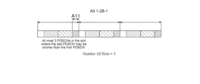
- FIG. 16 is a diagram explaining an example of Alt.1-2B-1.
- the number of consecutive slots for SPS PDSCH transmission allocated in the set SPS cycle is three.
- the terminal determines the maximum number of SPS PDSCHs allowed in the time domain in one slot based on the length of the SPS PDSCH and the length of the slot, May be implicitly determined.
- the maximum allowed number in a slot of SPS PDSCH is three.
- the length of the first SPS PDSCH in one slot and the length of the second SPS PDSCH are the same, but the length of the last SPS PDSCH in one slot may be shorter than the length of the other SPS PDSCHs. .
- the terminal may allocate the first SPS PDSCH to the slot based on TDRA.
- the terminal may continuously allocate SPS PDSCHs of the same length as the first SPS PDSCH so as to fit in the slot.
- the terminal may allocate an SPS PDSCH having a length shorter than the initial SPS PDSCH in resources (symbols) in which the consecutive SPS PDSCHs of the slots do not fit (for example, double-headed arrow A11 portion shown in FIG. 16).
- the last SPS PDSCH in a slot may be longer than the length of the first SPS PDSCH.
- the last CG PUSCH in a slot may be longer than the length of the first CG PUSCH.
- FIG. 17 is a diagram explaining an example of Alt.1-2B-2.
- the number of consecutive slots for SPS PDSCH transmission allocated in the set SPS period is two.
- the terminal determines the maximum number of SPS PDSCHs allowed in the time domain in one slot based on the length of the SPS PDSCH and the length of the slot, May be implicitly determined.
- the maximum allowed number in a slot of SPS PDSCH is two.
- the length of the second SPS PDSCH in one slot (the last SPS PDSCH in one slot) may be longer than the length of other SPS PDSCHs.
- the terminal may allocate the first SPS PDSCH to the slot based on TDRA.
- the terminal may continuously allocate SPS PDSCHs of the same length as the first SPS PDSCH so as to fit in the slot.
- the terminal uses the last SPS PDSCH (in the example of FIG. 17, the second SPS PDSCH). may be longer than other SPS PDSCHs.
- the last remaining symbols shorter than the length of the first SPS PDSCH in the slot may be dropped.
- the last remaining symbols shorter than the length of the first CG PUSCH in the slot may be dropped.
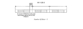
- FIG. 18 is a diagram explaining an example of Alt.1-2B-3.
- the number of consecutive slots for SPS PDSCH transmission allocated in the set SPS cycle is three.
- the terminal determines the maximum number of SPS PDSCHs allowed in the time domain in one slot based on the length of the SPS PDSCH and the length of the slot, May be implicitly determined.
- the maximum allowed number in a slot of SPS PDSCH is two.
- the terminal may drop the SPS PDSCH in resources shorter than the SPS PDSCH in one slot.
- the terminal may allocate the first SPS PDSCH to the slot based on TDRA.
- the terminal may continuously allocate SPS PDSCHs of the same length as the first SPS PDSCH so as to fit in the slot.
- the terminal does not need to drop (assign) SPS PDSCHs in resources (symbols) in which the consecutive SPS PDSCHs of the slots do not fit (for example, double-headed arrow A31 portion shown in FIG. 18).
- Multiple SPS PDSCHs may be allocated consecutively based on the TDRA in one period.
- Multiple CG PUSCHs may be allocated consecutively based on the TDRA in one period.
- multiple SPS PDSCHs may be allocated consecutively across slots like PUSCH-repetition type B.
- multiple CG PUSCHs may be allocated consecutively across slots.
- the nominal SPS PDSCH may be split into two actual PDSCHs, similar to PUSCH-repetition type B. If the CG PUSCH allocated by the TDRA spans slots, the nominal CG PUSCH may be split into two actual PUSCHs, similar to PUSCH-repetition type B.
- the number of SPS PDSCH and CG PUSCH may be counted based on Alt.2-1 or Alt.2-2 below.
- the number of SPS PDSCHs may be counted based on the nominal SPS PDSCH.
- the number of CG PUSCHs may be counted based on the nominal SPS PDSCH.
- FIG. 19 is a diagram explaining an example of Alt.2-1.
- a line A31a shown in FIG. 19 indicates a slot boundary.
- the number of SPS PDSCHs is counted based on the nominal SPS PDSCH. That is, the number of SPS PDSCHs is counted before one SPS PDSCH is divided by slots. For example, an SPS PDSCH divided at slot boundaries is counted as one.
- nominal SPS PDSCHs are allocated to resources as shown in FIG.
- the terminal decodes the nominal SPS PDSCH assigned to the resource.
- the number of SPS PDSCHs may be counted based on the actual SPS PDSCH.
- the number of CG PUSCHs may be counted based on the actual SPS PDSCH.
- FIG. 20 is a diagram explaining an example of Alt.2-2.
- a line A31b shown in FIG. 20 indicates a slot boundary.
- Alt.2-2 counts the number of SPS PDSCHs based on the actual SPS PDSCHs. That is, the number of SPS PDSCHs is counted after one SPS PDSCH is divided by slots. For example, SPS PDSCHs divided at slot boundaries are counted as two. Therefore, when the number of SPS PDSCHs in an SPS cycle is 4 and one SPS PDSCH spans slots, the actual SPS PDSCH is allocated to resources as shown in FIG. The terminal decodes the actual SPS PDSCH assigned to the resource.
- the number of SPS PDSCHs transmitted in the SPS period may be indicated by activation DCI (if present) or may be set by RRC.
- the number of SPS PDSCHs may be configured for each configured SPS or commonly for all configured SPSs.
- the number of CG PUSCHs transmitted in a CG period may be indicated by activation DCI (if present) or set by RRC.
- the number of CG PUSCHs may be set for each set CG or commonly for all set CGs.
- Parameters other than TDRA apply to multiple PDSCH, such as Frequency Domain Resource Allocation (FDRA), Modulation Coding Scheme (MCS), Redundancy Version (RV), Transmission Configuration Indication (TCI) state, or SRS resource indicator (SRI).
- FDRA Frequency Domain Resource Allocation
- MCS Modulation Coding Scheme
- RV Redundancy Version
- TCI Transmission Configuration Indication
- SRI SRS resource indicator
- FDRA Frequency Domain Resource Allocation
- MCS Modulation Coding Scheme
- RV Redundancy Version
- TCI Transmission Configuration Indication
- SRI SRS resource indicator
- the above parameters may be commonly indicated and/or commonly set for all SPS PDSCHs in one SPS cycle.
- the above parameters may be commonly indicated and/or commonly set for all CG PUSCHs in one CG cycle.
- the above parameters may be individually indicated and/or individually set for all SPS PDSCHs in one SPS period.
- the above parameters may be indicated and/or set individually for all CG PUSCHs in one CG cycle.
- rrc-ConfiguredUplinkGrant may be used for individual setting of the above parameters.
- rrc-ConfiguredUplinkGrant may be used for individual setting of the above parameters.
- separate fields for the above parameters may be included in the CG activation DCI and the SPS activation DCI.
- ⁇ Proposal 4> Actual transmission of PDSCH (reception in the terminal) may occur in all SPS PDSCHs or may be performed in some SPS PDSCHs in one SPS cycle. Actual transmission of PUSCH may be performed in all CG PUSCHs or in some CG PUSCHs in one CG period.
- the terminal may receive PDSCHs in 6 SPS PDSCHs of multiple PDSCHs shown in FIG. good too.
- the number of actual receptions in one SPS period and the number of actual transmissions in one CG period may be determined according to Alt.1 or Alt.2 below.
- the number of actual receptions in one SPS period may be determined by blind detection.
- the number of actual transmissions in one CG period may be determined by blind detection.
- the terminal may not perform blind detection on the SPS PDSCH following the certain SPS PDSCH.
- blind detection determination if the base station determines that there is no actual transmission on a CG PUSCH, the base station may not perform blind detection on the CG PUSCH following a CG PUSCH.
- the terminal determines that there is no actual reception in the second SPS PDSCH from the left end of the nine SPS PDSCHs of multiple PDSCHs shown in FIG. You don't have to perform number brand detection.
- the number of actual receptions in one SPS period may be signaled by control information included in the first SPS PDSCH in the SPS period.
- the number of actual transmissions in one CG period may be signaled by control information included in the first CG PUSCH in the CG period.
- the control information contained in the first SPS PDSCH in an SPS period may indicate that there are N actual PDSCH receptions in this SPS period.
- N may be a number less than or equal to the maximum number of SPS PDSCHs included in one SPS period.
- the terminal may not perform blind detection on the (N+1)-th SPS PDSCH included in one SPS period when N is less than the maximum number of SPS PDSCHs.
- the control information included in the first CG PUSCH in a CG period may indicate that there are N actual PUSCH transmissions in this CG period.
- N may be a number equal to or less than the maximum number of CG PUSCHs included in one CG period.
- the base station may not perform blind detection in the (N+1)-th PUSCH included in one CG period when N is less than the maximum number of CG PUSCHs.
- the terminal may blindly detect the SPS PDSCH at all SPS PDSCH reception opportunities. Note that even if the terminal determines that there is no actual reception in a certain SPS PDSCH in one SPS period, the terminal performs blind detection on the remaining SPS PDSCHs.
- Actual transmission may not occur in all CG PUSCHs of one CG cycle. For example, even though many CG PUSCH candidates are set in one slot in response to an XR service request, there may be cases where actual reception does not occur at a certain timing.
- the base station may blindly detect the CG PUSCH at all CG PUSCH reception opportunities. Note that even if the base station determines that there is no actual transmission in a certain CG PUSCH in one CG period, it blind-detects the remaining CG PUSCH.
- Proposal 5 describes HARQ-ACK feedback in one SPS period of multiple PDSCHs.
- HARQ-ACK timing ⁇ Alt.1>
- the timing of HARQ-ACK reporting may be determined separately for each SPS PDSCH. Therefore, HARQ-ACKs exist for the number of SPS PDSCHs, and a plurality of K1s may also exist.
- K1 may be indicated to the terminal by the activation DCI of each configured SPS PDSCH. Also, one K1 may be commonly applied in each SPS PDSCH that is indicated to the terminal by the activation DCI and configured.
- HARQ-ACK feedback for multiple SPS PDSCHs in one SPS period may be reported in one PUCCH.
- HARQ-ACKs of nine SPS PDSCHs shown in FIG. 16 may be reported in one PUCCH.
- the PUCCH transmission timing may be determined based on K1 indicated by the activation DCI and the first or last SPS PDSCH slot of the SPS period.
- FIG. 21 is a diagram illustrating an example of HARQ-ACK ordering in Type 1 HARQ-ACK CB of multiple PDSCHs.
- HARQ-ACKs of SPS PDSCHs in multiple PDSCHs are arranged in ascending order of starting symbols (numbers) of SPS PDSCHs in each DL slot number of each SPS configuration index in each serving cell index.
- the SPS PDSCH HARQ-ACKs are then ordered in ascending order of DL slot number at each SPS configuration index for each serving cell index.
- the SPS PDSCH HARQ-ACKs are then ordered in ascending order of SPS configuration index in each serving cell index.
- the SPS PDSCH HARQ-ACKs are then ordered in ascending order of serving cell index.
- HARQ-ACKs may be ordered in the same way as the Type 1 HARQ-ACK CB described above.
- Type 2 HARQ-ACK CB when HARQ-ACK of SPS PDSCH reception is multiplexed with HARQ-ACK of dynamically scheduled PDSCH reception and/or HARQ-ACK of deactivation DCI, SPS PDSCH reception The HARQ-ACK(bits) is appended (following in time) the HARQ-ACK(bits) of the dynamically scheduled PDSCH reception and/or the HARQ-ACK(bits) of the deactivation DCI.
- Type 1 HARQ-ACK feedback in SPS PDSCH and dynamic PDSCH of multiple PDSCHs If individual TDRA is indicated and/or set for each SPS PDSCH (for example, see Opt.1 of Proposal 2), Type 1
- the HARQ-ACK CB generation procedure may follow the generation procedure in Rel.-15 or Rel.-16. Also, the Type 1 HARQ-ACK CB generation procedure may follow the HARQ-ACK CB generation procedure for multi-PDSCH scheduling under discussion in Rel.-17.
- Opt.1 or Opt.2 may be applied.
- Multiple candidate PDSCH reception opportunities in one SLIV may be determined as follows.
- FIG. 22 is a diagram illustrating an example of candidate PDSCH reception opportunities.
- the number N of multiple candidate PDSCH reception opportunities for one SLIV may be determined by the maximum number of SPS PDSCHs in one slot. good.
- the number N of candidate PDSCH reception opportunities may be 3 if the timing of HARQ-ACK reporting is determined individually for each SPS PDSCH.
- the number of multiple candidate PDSCH reception opportunities for one SLIV is the maximum number of SPS PDSCHs in one SPS cycle may be determined by
- the number of candidate PDSCH reception opportunities may be nine.
- One candidate PDSCH reception opportunity in one SLIV may be determined as follows.
- the PDSCH slot set (PDSCH slot window) may be extended or the K1 set may be extended.
- the PDSCH slot set or K1 set may be expanded based on the maximum number of PDSCH slots in one SPS period.
- the PDSCH slot set or K1 set consists of "maximum number of PDSCH slots in one SPS period" and "maximum number of PDSCH slots for multiple PDSCH scheduling by one DCI". may be expanded based on the maximum value between
- FIG. 23 is a diagram explaining an example of an extended PDSCH slot set.
- One SPS cycle includes multiple SPS PDSCHs.
- the PDSCH slot set may be extended as indicated by dotted line frame A41a in FIG.
- a dotted line frame A41b in FIG. 23 indicates, for example, a PDSCH slot set obtained from the value of K1 of the first SPS PDSCH in one SPS cycle.
- a candidate PDSCH reception opportunity in each candidate PDSCH slot after the K1 extension may be determined based on the set of SLIVs for each row of the TDRA table.
- Opt.2-1 of Proposal 5 is the case of slot-based multiple PDSCHs in which one PDSCH is included in one slot, and HARQ-ACK for multiple SPS PDSCHs in one SPS period is 1 applied when reported on one PUCCH.
- Opt.2-1 of Proposal 5 is applied to the Alt.1-1 case of Opt.2 of Proposal 2 (see, for example, FIG. 14).
- the PDSCH slot set may be extended and each row of the TDRA table may be extended.
- Step 1 The PDSCH slot set or K1 set is extended in the same manner as Step 1 of Opt.2-1 above.
- SLIV may be extended assuming that the SLIV of the original TDRA table is the first PDSCH (SPS PDSCH) of one slot. SLIVs of PDSCHs following the first PDSCH in the same slot may be added to the TDRA table row.
- SPS PDSCH first PDSCH
- FIG. 24 is a diagram explaining an extension example of SLIV.
- the table shown in the lower left of FIG. 24 shows the original TDRA table.
- the original TDRA table contains the SILV of the first PDSCH in one slot.
- the table shown in the lower right of Fig. 24 shows the extended TDRA table.
- the extended TDRA table includes the SILV of the PDSCH following the first PDSCH in addition to the SILV of the first PDSCH in one slot.
- Candidate PDSCH reception opportunities in each candidate PDSCH slot after K1 extension may be determined based on the SLIV set for each row of the extended TDRA table.
- Opt.2-2 of Proposal 5 is the case of slot-based multiple PDSCH in which multiple PDSCHs are included in one slot, and HARQ-ACK for multiple SPS PDSCHs in one SPS period is 1 applied when reported on one PUCCH.
- Opt.2-2 of Proposal 5 is applied to the Alt.1-2 case of Opt.2 of Proposal 2 (see, for example, FIG. 15).
- SLIV may be extended in each row of the TDRA table.
- SLIV may be extended assuming that SLIV is the first PDSCH of one SPS period.
- the SLIVs of the PDSCHs following the first PDSCH in one SPS period may be added to the TDRA table rows assuming the maximum number of SPS PDSCHs in one SPS period.
- FIG. 25 is a diagram explaining an extension example of SLIV.
- the table shown in the lower left of FIG. 25 shows the original TDRA table.
- the original TDRA table contains the SILV of the first PDSCH in one slot.
- the table shown in the lower right of FIG. 25 shows the expanded TDRA table.
- the extended TDRA table includes the SILV of the first PDSCH in one SPS period as well as the SILV of the PDSCHs following the first PDSCH.
- the determination of candidate PDSCH slots and candidate PDSCH reception opportunities may follow the multiple PDSCH scheduling determination of Rel.-17.
- Opt.2-3 of Proposal 5 is applied to the case of slot-based multiple PDSCHs in which one PDSCH is included in one slot and to the case of slot-based multiple PDSCH in which one slot includes multiple PDSCHs. be.
- Opt.2-3 of Proposal 5 is applied to Alt.1 and Alt.2 of Opt.2 of Proposal 2 (see, eg, FIGS. 14-18).
- the UE capability indicating the capability of the UE may include the following information indicating the capability of the UE. Note that the information indicating the capabilities of the UE may correspond to information defining the capabilities of the UE.
- the radio communication system includes base station 10 shown in FIG.26 and terminal 20 shown in FIG.27.
- the number of base stations 10 and the number of terminals 20 are not particularly limited.
- the wireless communication system may be a wireless communication system according to New Radio (NR).
- NR New Radio
- the wireless communication system may be a wireless communication system according to a scheme called URLLC and/or IIoT.
- the wireless communication system may be a wireless communication system that conforms to a system called 5G, Beyond 5G, 5G Evolution, or 6G.
- the base station 10 may be called an NG-RAN Node, ng-eNB, eNodeB (eNB), or gNodeB (gNB).
- the terminal 20 may be called User Equipment (UE).
- the base station 10 may be regarded as a device included in the network to which the terminal 20 connects.
- the radio communication system may include Next Generation-Radio Access Network (NG-RAN).
- NG-RAN includes multiple NG-RAN Nodes, specifically gNBs (or ng-eNBs), and is connected to a 5G-compliant core network (5GC, not shown).
- 5GC 5G-compliant core network
- NG-RAN and 5GC may be simply referred to as "networks”.
- the base station 10 performs wireless communication with the terminal 20.
- the wireless communication performed complies with NR.
- At least one of the base station 10 and the terminal 20 uses Massive MIMO (Multiple-Input Multiple-Output) to generate beams (BM) with higher directivity by controlling radio signals transmitted from a plurality of antenna elements. You can respond.
- at least one of the base station 10 and the terminal 20 may support carrier aggregation (CA) that uses multiple component carriers (CC) in a bundle.
- CA carrier aggregation
- CC component carriers
- at least one of the base station 10 and the terminal 20 may support dual connectivity (DC), etc., in which communication is performed between the terminal 20 and each of the plurality of base stations 10 .
- a wireless communication system may support multiple frequency bands.
- a wireless communication system supports Frequency Ranges (FR) 1 and FR2.
- the frequency bands of each FR are, for example, as follows. ⁇ FR1: 410MHz to 7.125GHz ⁇ FR2: 24.25GHz to 52.6GHz
- FR1 Sub-Carrier Spacing (SCS) of 15 kHz, 30 kHz or 60 kHz may be used, and a bandwidth (BW) of 5 MHz to 100 MHz may be used.
- SCS Sub-Carrier Spacing
- BW bandwidth
- FR2 is, for example, a higher frequency than FR1.
- FR2 may use an SCS of 60 kHz or 120 kHz and a bandwidth (BW) of 50 MHz to 400 MHz.
- FR2 may include a 240 kHz SCS.
- the wireless communication system in this embodiment may support a frequency band higher than the frequency band of FR2.
- the wireless communication system in this embodiment can support frequency bands exceeding 52.6 GHz and up to 114.25 GHz.
- Such high frequency bands may be referred to as "FR2x.”
- Cyclic Prefix-Orthogonal Frequency Division Multiplexing CP-OFDM
- DFT-S-OFDM Discrete Fourier Transform - Spread - Orthogonal Frequency Division Multiplexing
- SCS Sub-Carrier Spacing
- DFT-S-OFDM may be applied to both uplink and downlink, or may be applied to either one.
- a time division duplex (TDD) slot configuration pattern may be set.
- slots for transmitting downlink (DL) signals, slots for transmitting uplink (UL) signals, slots in which DL signals, UL signals and guard symbols are mixed, and signals to be transmitted are flexible
- a pattern may be defined that indicates the order of two or more of the slots to be changed to .
- channel estimation of PUSCH can be performed using a demodulation reference signal (DMRS) for each slot.
- DMRS demodulation reference signal
- Such channel estimation may be called joint channel estimation. Alternatively, it may be called by another name such as cross-slot channel estimation.
- the terminal 20 may transmit the DMRS assigned to each of the multiple slots so that the base station 10 can perform joint channel estimation using DMRS.
- an enhanced function may be added to the feedback function from the terminal 20 to the base station 10.
- enhanced functionality of terminal feedback for HARQ-ACK may be added.
- the configurations of the base station 10 and the terminal 20 will be explained. It should be noted that the configurations of the base station 10 and the terminal 20 described below are examples of functions related to the present embodiment.
- the base station 10 and terminal 20 may have functions not shown. Also, the functional division and/or the name of the functional unit are not limited as long as the function executes the operation according to the present embodiment.
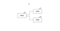
- FIG. 26 is a block diagram showing an example of the configuration of base station 10 according to this embodiment.
- the base station 10 includes a transmitter 101, a receiver 102, and a controller 103, for example.
- the base station 10 wirelessly communicates with the terminal 20 (see FIG. 27).
- the transmission section 101 transmits a downlink (DL) signal to the terminal 20 .
- the transmitter 101 transmits a DL signal under the control of the controller 103 .
- a DL signal may include, for example, a downlink data signal and control information (eg, Downlink Control Information (DCI)).
- DCI Downlink Control Information
- the DL signal may include information (for example, UL grant) indicating scheduling regarding signal transmission of the terminal 20 .
- the DL signal may include higher layer control information (for example, Radio Resource Control (RRC) control information).
- RRC Radio Resource Control
- the DL signal may include a reference signal.
- Channels used for transmitting DL signals include, for example, data channels and control channels.
- the data channel may include a PDSCH (Physical Downlink Shared Channel)
- the control channel may include a PDCCH (Physical Downlink Control Channel).
- the base station 10 transmits control information to the terminal 20 using the PDCCH, and transmits downlink data signals using the PDSCH.
- reference signals included in DL signals include demodulation reference signals (DMRS), phase tracking reference signals (PTRS), channel state information-reference signals (CSI-RS), sounding reference signals (SRS ), and Positioning Reference Signal (PRS) for position information.
- DMRS demodulation reference signals
- PTRS phase tracking reference signals
- CSI-RS channel state information-reference signals
- SRS sounding reference signals
- PRS Positioning Reference Signal
- reference signals such as DMRS and PTRS are used for demodulation of downlink data signals and transmitted using PDSCH.
- the receiving unit 102 receives an uplink (UL) signal transmitted from the terminal 20 .
- the receiver 102 receives UL signals under the control of the controller 103 .
- the control unit 103 controls the communication operation of the base station 10, including the transmission processing of the transmission unit 101 and the reception processing of the reception unit 102.
- control unit 103 acquires information such as data and control information from the upper layer and outputs it to the transmission unit 101 . Also, the control unit 103 outputs the data and control information received from the receiving unit 102 to the upper layer.
- control unit 103 based on the signal received from the terminal 20 (e.g., data and control information, etc.) and / or data and control information obtained from the upper layer, resource (or channel) used for transmission and reception of the DL signal and/or allocates resources used for transmission and reception of UL signals. Information about the allocated resources may be included in control information to be transmitted to the terminal 20 .
- the control unit 103 sets PUCCH resources as an example of allocation of resources used for transmission and reception of UL signals.
- Information related to PUCCH configuration such as the PUCCH cell timing pattern may be notified to the terminal 20 by RRC.
- FIG. 27 is a block diagram showing an example of the configuration of terminal 20 according to this embodiment.
- Terminal 20 includes, for example, receiver 201 , transmitter 202 , and controller 203 .
- the terminal 20 communicates with the base station 10 by radio, for example.
- the receiving unit 201 receives the DL signal transmitted from the base station 10. For example, the receiver 201 receives a DL signal under the control of the controller 203 .
- the transmission unit 202 transmits the UL signal to the base station 10.
- the transmitter 202 transmits UL signals under the control of the controller 203 .
- the UL signal may include, for example, an uplink data signal and control information (eg, UCI).
- control information eg, UCI
- information about the processing capability of terminal 20 eg, UE capability
- the UL signal may include a reference signal.
- Channels used to transmit UL signals include, for example, data channels and control channels.
- the data channel includes PUSCH (Physical Uplink Shared Channel)
- the control channel includes PUCCH (Physical Uplink Control Channel).
- the terminal 20 receives control information from the base station 10 using PUCCH, and transmits uplink data signals using PUSCH.
- the reference signal included in the UL signal may include at least one of DMRS, PTRS, CSI-RS, SRS, and PRS, for example.
- reference signals such as DMRS and PTRS are used for demodulation of uplink data signals and transmitted using an uplink channel (eg, PUSCH).
- the control unit 203 controls communication operations of the terminal 20, including reception processing in the reception unit 201 and transmission processing in the transmission unit 202.
- control unit 203 acquires information such as data and control information from the upper layer and outputs it to the transmission unit 202 . Also, the control unit 203 outputs, for example, the data and control information received from the receiving unit 201 to an upper layer.
- control unit 203 controls transmission of information to be fed back to the base station 10 .
- Information fed back to the base station 10 may include, for example, HARQ-ACK, channel state information (CSI), or scheduling request (SR). good.
- Information to be fed back to the base station 10 may be included in the UCI.
- UCI is transmitted on PUCCH resources.
- the control unit 203 configures PUCCH resources based on configuration information received from the base station 10 (for example, configuration information such as the PUCCH cell timing pattern notified by RRC and/or DCI).
- Control section 203 determines PUCCH resources to be used for transmitting information to be fed back to base station 10 .
- transmission section 202 transmits information to be fed back to base station 10 on PUCCH resources determined by control section 203 .
- the channels used for DL signal transmission and the channels used for UL signal transmission are not limited to the above examples.
- the channel used for DL signal transmission and the channel used for UL signal transmission may include RACH (Random Access Channel) and PBCH (Physical Broadcast Channel).
- RACH may be used, for example, to transmit Downlink Control Information (DCI) containing Random Access Radio Network Temporary Identifier (RA-RNTI).
- DCI Downlink Control Information
- RA-RNTI Random Access Radio Network Temporary Identifier
- the control unit 203 may set the reception cycle of the DL signal based on the cycle setting information.
- Receiving section 201 may receive a DL signal using a plurality of SPS PDSCHs in each set reception cycle.
- the period setting information may be, for example, RRC parameters.
- the receiving section 201 may receive DL signals using multiple SPS PDSCHs in multiple consecutive slots. For example, as shown in FIG. 14, receiving section 201 may receive DL signals using one SPS PDSCH included in each of a plurality of slots. Receiving section 201 may receive DL signals using a plurality of SPS PDSCHs included in each of a plurality of slots, as shown in FIGS. 15 to 18, for example.
- the terminal 20 can perform SPS PDSCH communication suitable for large-capacity communication.
- the receiving section 201 may receive transmission cycle setting information in the UL signal and individual TDRAs in a plurality of CG PUSCHs that transmit the UL signal.
- Control section 203 may allocate CG PUSCH to resources based on individual TDRAs for each transmission cycle of the received configuration information.
- the configuration information may be, for example, RRC parameters.
- the receiving section 201 may receive the TDRA using, for example, higher layer signaling such as RRC signaling.
- RRC signaling may also be referred to as RRC messages or RRC information elements.
- the terminal 20 can perform CG PUSCH communication suitable for large-capacity communication.
- Control section 203 determines the leading CG PUSCH in one slot based on TDRA for each transmission cycle of the received configuration information, and adjusts the trailing CG PUSCH in one slot to fit within the rear boundary of one slot. may decide. For example, as shown in FIGS. 16 and 17, control section 203 determines the leading CG PUSCH in one slot based on TDRA, and places the trailing CG PUSCH in one slot at the rear boundary of one slot. You can decide to fit. Control section 203 may continuously allocate a plurality of CG PUSCHs to resources in one slot.
- the terminal 20 can perform CG PUSCH communication suitable for large-capacity communication.
- the receiving section 201 may receive the DL signal using a plurality of SPS PDSCHs at each set reception cycle, and the transmitting section 202 may transmit a DL signal response signal. Transmitting section 202 may transmit the response signal using one PUCCH.
- the response signal may be, for example, HARQ-ACK.
- the receiving unit 201 and the transmitting unit 202 may be called a communication unit.
- the control unit 203 may determine the number of candidate reception opportunities for multiple SPS PDSCHs based on the maximum number of SPS PDSCHs in one slot. Control section 203 may determine the number of candidate reception opportunities for multiple SPS PDSCHs based on the maximum number of multiple SPS PDSCHs in each reception cycle. Control section 203 may determine a slot set of multiple SPS PDSCHs to which response signals are to be transmitted, based on the maximum number of multiple SPS PDSCHs in each reception cycle.
- terminal 20 can appropriately report HARQ-ACK of SPS PDSCH suitable for large-capacity communication.
- each functional block may be implemented using one device that is physically or logically coupled, or directly or indirectly using two or more devices that are physically or logically separated (e.g. , wired, wireless, etc.) and may be implemented using these multiple devices.
- a functional block may be implemented by combining software in the one device or the plurality of devices.
- Functions include judging, determining, determining, calculating, calculating, processing, deriving, investigating, searching, checking, receiving, transmitting, outputting, accessing, resolving, selecting, choosing, establishing, comparing, assuming, expecting, assuming, Broadcasting, notifying, communicating, forwarding, configuring, reconfiguring, allocating, mapping, assigning, etc. can't
- a functional block (component) that makes transmission work is called a transmitting unit or transmitter.
- the implementation method is not particularly limited.
- a base station, a terminal, etc. may function as a computer that performs processing of the wireless communication method of the present disclosure.
- FIG. 28 is a diagram illustrating an example of hardware configurations of a base station and a terminal according to an embodiment of the present disclosure;
- the base station 10 and terminal 20 described above may be physically configured as a computer device including a processor 1001, a memory 1002, a storage 1003, a communication device 1004, an input device 1005, an output device 1006, a bus 1007, and the like.
- the term "apparatus” can be read as a circuit, device, unit, or the like.
- the hardware configuration of the base station 10 and terminal 20 may be configured to include one or more of each device shown in the figure, or may be configured without some devices.
- Each function of the base station 10 and the terminal 20 is performed by the processor 1001 by loading predetermined software (program) onto hardware such as the processor 1001 and the memory 1002, and the processor 1001 performs calculations and controls communication by the communication device 1004. , and controlling at least one of reading and writing of data in the memory 1002 and the storage 1003 .
- the processor 1001 for example, operates an operating system and controls the entire computer.
- the processor 1001 may be configured by a central processing unit (CPU) including an interface with peripheral devices, a control device, an arithmetic device, registers, and the like.
- CPU central processing unit
- the control unit 103 and the control unit 203 described above may be implemented by the processor 1001 .
- the processor 1001 reads programs (program codes), software modules, data, etc. from at least one of the storage 1003 and the communication device 1004 to the memory 1002, and executes various processes according to them.
- programs program codes
- software modules software modules
- data etc.
- the control unit 203 of the terminal 20 may be implemented by a control program stored in the memory 1002 and running on the processor 1001, and other functional blocks may be similarly implemented.
- FIG. Processor 1001 may be implemented by one or more chips.
- the program may be transmitted from a network via an electric communication line.
- the memory 1002 is a computer-readable recording medium, and is composed of at least one of, for example, ROM (Read Only Memory), EPROM (Erasable Programmable ROM), EEPROM (Electrically Erasable Programmable ROM), and RAM (Random Access Memory). may be
- ROM Read Only Memory
- EPROM Erasable Programmable ROM
- EEPROM Electrical Erasable Programmable ROM
- RAM Random Access Memory
- the memory 1002 may also be called a register, cache, main memory (main storage device), or the like.
- the memory 1002 can store executable programs (program code), software modules, etc. for implementing a wireless communication method according to an embodiment of the present disclosure.
- the storage 1003 is a computer-readable recording medium, for example, an optical disk such as a CD-ROM (Compact Disc ROM), a hard disk drive, a flexible disk, a magneto-optical disk (for example, a compact disk, a digital versatile disk, a Blu-ray disk), smart card, flash memory (eg, card, stick, key drive), floppy disk, magnetic strip, and/or the like.
- Storage 1003 may also be called an auxiliary storage device.
- the storage medium described above may be, for example, a database, server, or other suitable medium including at least one of memory 1002 and storage 1003 .
- the communication device 1004 is hardware (transmitting/receiving device) for communicating between computers via at least one of a wired network and a wireless network, and is also called a network device, a network controller, a network card, a communication module, or the like.
- the communication device 1004 includes a high-frequency switch, a duplexer, a filter, a frequency synthesizer, and the like, for example, to realize at least one of frequency division duplex (FDD) and time division duplex (TDD).
- FDD frequency division duplex
- TDD time division duplex
- the transmitting unit 101 , the receiving unit 102 , the receiving unit 201 , the transmitting unit 202 and the like described above may be implemented by the communication device 1004 .
- the input device 1005 is an input device (for example, keyboard, mouse, microphone, switch, button, sensor, etc.) that receives input from the outside.
- the output device 1006 is an output device (eg, display, speaker, LED lamp, etc.) that outputs to the outside. Note that the input device 1005 and the output device 1006 may be integrated (for example, a touch panel).
- Each device such as the processor 1001 and the memory 1002 is connected by a bus 1007 for communicating information.
- the bus 1007 may be configured using a single bus, or may be configured using different buses between devices.
- the base station 10 and the terminal 20 include hardware such as microprocessors, digital signal processors (DSPs), ASICs (Application Specific Integrated Circuits), PLDs (Programmable Logic Devices), and FPGAs (Field Programmable Gate Arrays). , and part or all of each functional block may be implemented by the hardware.
- processor 1001 may be implemented using at least one of these pieces of hardware.
- Notification of information is not limited to the embodiments described in the present disclosure, and may be performed using other methods.
- notification of information includes physical layer signaling (e.g., DCI (Downlink Control Information), UCI (Uplink Control Information)), higher layer signaling (e.g., RRC (Radio Resource Control) signaling, MAC (Medium Access Control) signaling, It may be implemented by broadcast information (MIB (Master Information Block), SIB (System Information Block)), other signals, or a combination thereof.
- RRC signaling may also be called an RRC message, and may be, for example, an RRC connection setup message, an RRC connection reconfiguration message, or the like.
- Embodiments described in the present disclosure are LTE (Long Term Evolution), LTE-A (LTE-Advanced), SUPER 3G, IMT-Advanced, 4G (4th generation mobile communication system), 5G (5th generation mobile communication system) , FRA (Future Radio Access), NR (new Radio), W-CDMA (registered trademark), GSM (registered trademark), CDMA2000, UMB (Ultra Mobile Broadband), IEEE 802.11 (Wi-Fi (registered trademark)) , IEEE 802.16 (WiMAX®), IEEE 802.20, UWB (Ultra-WideBand), Bluetooth®, other suitable systems and next generations based on these It may be applied to at least one of the systems. Also, a plurality of systems may be applied in combination (for example, a combination of at least one of LTE and LTE-A and 5G, etc.).
- various operations performed for communication with a terminal may be performed by the base station and other network nodes other than the base station (e.g. MME or S-GW, etc. (including but not limited to).
- MME or S-GW network nodes other than the base station
- the case where there is one network node other than the base station is exemplified above, it may be a combination of a plurality of other network nodes (for example, MME and S-GW).
- ⁇ Direction of input/output> Information and the like can be output from a higher layer (or a lower layer) to a lower layer (or a higher layer). It may be input and output via multiple network nodes.
- Input/output information and the like may be stored in a specific location (for example, memory), or may be managed using a management table. Input/output information and the like can be overwritten, updated, or appended. The output information and the like may be deleted. The entered information and the like may be transmitted to another device.
- the determination may be made by a value represented by one bit (0 or 1), by a true/false value (Boolean: true or false), or by numerical comparison (for example, a predetermined value).
- notification of predetermined information is not limited to being performed explicitly, but may be performed implicitly (for example, not notifying the predetermined information). good too.
- Software whether referred to as software, firmware, middleware, microcode, hardware description language or otherwise, includes instructions, instruction sets, code, code segments, program code, programs, subprograms, and software modules. , applications, software applications, software packages, routines, subroutines, objects, executables, threads of execution, procedures, functions, and the like.
- software, instructions, information, etc. may be transmitted and received via a transmission medium.
- the software may use wired technology (coaxial cable, fiber optic cable, twisted pair, Digital Subscriber Line (DSL), etc.) and/or wireless technology (infrared, microwave, etc.) to access websites, Wired and/or wireless technologies are included within the definition of transmission medium when sent from a server or other remote source.
- wired technology coaxial cable, fiber optic cable, twisted pair, Digital Subscriber Line (DSL), etc.
- wireless technology infrared, microwave, etc.
- Information, signals, etc. described in this disclosure may be represented using any of a variety of different technologies.
- data, instructions, commands, information, signals, bits, symbols, chips, etc. may refer to voltages, currents, electromagnetic waves, magnetic fields or magnetic particles, light fields or photons, or any of these. may be represented by a combination of
- the channel and/or symbols may be signaling.
- a signal may also be a message.
- a component carrier may also be referred to as a carrier frequency, cell, frequency carrier, or the like.
- ⁇ Name of parameter and channel> the information, parameters, etc. described in the present disclosure may be expressed using absolute values, may be expressed using relative values from a predetermined value, or may be expressed using other corresponding information. may be represented. For example, radio resources may be indexed.
- Base station In the present disclosure, “base station (BS)”, “radio base station”, “fixed station”, “NodeB”, “eNodeB (eNB)”, “gNodeB (gNB)”, “"accesspoint”,”transmissionpoint”,”receptionpoint”,”transmission/receptionpoint”,”cell”,”sector”,”cellgroup”,” Terms such as “carrier”, “component carrier” may be used interchangeably.
- a base station may also be referred to by terms such as macrocell, small cell, femtocell, picocell, and the like.
- a base station can accommodate one or more (eg, three) cells.
- the overall coverage area of the base station can be partitioned into multiple smaller areas, each smaller area being associated with a base station subsystem (e.g., an indoor small base station (RRH:
- RRH indoor small base station
- the term "cell” or “sector” refers to part or all of the coverage area of at least one of the base stations and base station subsystems serving communication services in this coverage.
- MS Mobile Station
- UE User Equipment
- a mobile station is defined by those skilled in the art as a subscriber station, mobile unit, subscriber unit, wireless unit, remote unit, mobile device, wireless device, wireless communication device, remote device, mobile subscriber station, access terminal, mobile terminal, wireless It may also be called a terminal, remote terminal, handset, user agent, mobile client, client, or some other suitable term.
- At least one of a base station and a mobile station may be called a transmitter, a receiver, a communication device, and the like. At least one of the base station and the mobile station may be a device mounted on a mobile object, the mobile object itself, or the like.
- the mobile object may be a vehicle (e.g., car, airplane, etc.), an unmanned mobile object (e.g., drone, self-driving car, etc.), or a robot (manned or unmanned ).
- at least one of the base station and the mobile station includes devices that do not necessarily move during communication operations.
- at least one of the base station and the mobile station may be an IoT (Internet of Things) device such as a sensor.
- IoT Internet of Things
- the base station in the present disclosure may be read as a terminal.
- the terminal 20 may have the functions of the base station 10 described above.
- words such as "up” and “down” may be replaced with words corresponding to inter-terminal communication (for example, "side").
- uplink channels, downlink channels, etc. may be read as side channels.
- a terminal in the present disclosure may be read as a base station.
- the base station 10 may have the functions of the terminal 20 described above.
- determining may encompass a wide variety of actions.
- “Judgement”, “determining” are, for example, judging, calculating, computing, processing, deriving, investigating, looking up, searching, inquiring (eg, lookup in a table, database, or other data structure), ascertaining as “judged” or “determined”, and the like.
- "judgment” and “decision” are used for receiving (e.g., receiving information), transmitting (e.g., transmitting information), input, output, access (accessing) (for example, accessing data in memory) may include deeming that something has been "determined” or “decided”.
- judgment and “decision” are considered to be “judgment” and “decision” by resolving, selecting, choosing, establishing, comparing, etc. can contain.
- judgment and “decision” may include considering that some action is “judgment” and “decision”.
- judgment (decision) may be read as “assuming”, “expecting”, “considering”, or the like.
- connection means any direct or indirect connection or connection between two or more elements, It can include the presence of one or more intermediate elements between two elements being “connected” or “coupled.” Couplings or connections between elements may be physical, logical, or a combination thereof. For example, “connection” may be read as "access”.
- two elements are defined using at least one of one or more wires, cables, and printed electrical connections and, as some non-limiting and non-exhaustive examples, in the radio frequency domain. , electromagnetic energy having wavelengths in the microwave and optical (both visible and invisible) regions, and the like.
- the reference signal may be abbreviated as RS (Reference Signal), or may be referred to as Pilot according to the applicable standard.
- a radio frame may consist of one or more frames in the time domain. Each frame or frames in the time domain may be referred to as a subframe. A subframe may also consist of one or more slots in the time domain. A subframe may be a fixed time length (eg, 1 ms) independent of numerology.
- a numerology may be a communication parameter that applies to the transmission and/or reception of a signal or channel. Numerology, for example, subcarrier spacing (SCS), bandwidth, symbol length, cyclic prefix length, transmission time interval (TTI), number of symbols per TTI, radio frame structure, transmission and reception specific filtering operations performed by the receiver in the frequency domain, specific windowing operations performed by the transceiver in the time domain, and/or the like.
- SCS subcarrier spacing
- TTI transmission time interval
- number of symbols per TTI radio frame structure
- transmission and reception specific filtering operations performed by the receiver in the frequency domain specific windowing operations performed by the transceiver in the time domain, and/or the like.
- a slot may consist of one or more symbols (OFDM (Orthogonal Frequency Division Multiplexing) symbol, SC-FDMA (Single Carrier Frequency Division Multiple Access) symbol, etc.) in the time domain.
- a slot may be a unit of time based on numerology.
- a slot may contain multiple mini-slots. Each minislot may consist of one or more symbols in the time domain. A minislot may also be referred to as a subslot. A minislot may consist of fewer symbols than a slot.
- PDSCH (or PUSCH) transmitted in time units larger than minislots may be referred to as PDSCH (or PUSCH) mapping type A.
- PDSCH (or PUSCH) transmitted using minislots may be referred to as PDSCH (or PUSCH) mapping type B.
- Radio frames, subframes, slots, minislots and symbols all represent time units when transmitting signals. Radio frames, subframes, slots, minislots and symbols may be referred to by other corresponding designations.
- one subframe may be called a Transmission Time Interval (TTI)
- TTI Transmission Time Interval
- multiple consecutive subframes may be called a TTI
- one slot or minislot may be called a TTI.
- TTI Transmission Time Interval
- at least one of the subframe and TTI may be a subframe (1 ms) in existing LTE, a period shorter than 1 ms (eg, 1-13 symbols), or a period longer than 1 ms may be Note that the unit representing the TTI may be called a slot, mini-slot, or the like instead of a subframe.
- TTI refers to, for example, the minimum scheduling time unit in wireless communication.
- a base station performs scheduling to allocate radio resources (frequency bandwidth, transmission power, etc. that can be used by each user terminal) to each user terminal on a TTI basis.
- radio resources frequency bandwidth, transmission power, etc. that can be used by each user terminal
- a TTI may be a transmission time unit such as a channel-encoded data packet (transport block), code block, or codeword, or may be a processing unit such as scheduling and link adaptation. Note that when a TTI is given, the time interval (for example, the number of symbols) in which transport blocks, code blocks, codewords, etc. are actually mapped may be shorter than the TTI.
- one or more TTIs may be the minimum scheduling time unit. Also, the number of slots (the number of mini-slots) constituting the minimum time unit of the scheduling may be controlled.
- a TTI having a time length of 1 ms may be called a normal TTI (TTI in LTE Rel. 8-12), normal TTI, long TTI, normal subframe, normal subframe, long subframe, slot, or the like.
- TTI that is shorter than a regular TTI may also be called a shortened TTI, a short TTI, a partial or fractional TTI, a shortened subframe, a short subframe, a minislot, a subslot, a slot, and so on.
- the long TTI (e.g., normal TTI, subframe, etc.) may be replaced with a TTI having a time length exceeding 1 ms
- the short TTI e.g., shortened TTI, etc.
- a TTI having the above TTI length may be read instead.
- a resource block is a resource allocation unit in the time domain and the frequency domain, and may include one or more consecutive subcarriers in the frequency domain.
- the number of subcarriers included in the RB may be the same regardless of the neumerology, eg twelve.
- the number of subcarriers included in an RB may be determined based on neumerology.
- the time domain of an RB may include one or more symbols and may be 1 slot, 1 minislot, 1 subframe, or 1 TTI long.
- One TTI, one subframe, etc. may each consist of one or more resource blocks.
- One or more RBs are physical resource blocks (PRBs), sub-carrier groups (SCGs), resource element groups (REGs), PRB pairs, RB pairs, etc. may be called.
- PRBs physical resource blocks
- SCGs sub-carrier groups
- REGs resource element groups
- PRB pairs RB pairs, etc. may be called.
- a resource block may be composed of one or more resource elements (RE: Resource Element).
- RE Resource Element
- 1 RE may be a radio resource region of 1 subcarrier and 1 symbol.
- a bandwidth part (which may also be called a bandwidth part) represents a subset of contiguous common resource blocks (RBs) for a numerology on a carrier. good.
- the common RB may be identified by an RB index based on the common reference point of the carrier.
- PRBs may be defined in a BWP and numbered within that BWP.
- the BWP may include a BWP for UL (UL BWP) and a BWP for DL (DL BWP).
- UL BWP UL BWP
- DL BWP DL BWP
- One or multiple BWPs may be configured for a UE within one carrier.
- At least one of the configured BWPs may be active, and the UE may not expect to transmit or receive a given signal/channel outside the active BWP.
- BWP bitmap
- radio frames, subframes, slots, minislots and symbols described above are only examples.
- the number of subframes contained in a radio frame the number of slots per subframe or radio frame, the number of minislots contained within a slot, the number of symbols and RBs contained in a slot or minislot, the number of Configurations such as the number of subcarriers and the number of symbols in a TTI, symbol length, cyclic prefix (CP) length, etc.
- CP cyclic prefix
- Maximum transmit power as described in this disclosure may mean the maximum value of transmit power, may mean the nominal UE maximum transmit power, or may refer to the rated maximum transmit power ( the rated UE maximum transmit power).
- One aspect of the present disclosure is useful for wireless communication systems.
Abstract
This terminal comprises: a reception unit that receives setting information of the transmission period in an uplink signal and also receives individual time-domain resource allocation information in each of a plurality of uplink channels for which the uplink signal is transmitted; and a control unit that allocates, in each transmission period, the plurality of uplink channels to resources on the basis of the individual time-domain resource allocation information.
Description
本開示は、端末及び無線通信方法に関する。
The present disclosure relates to terminals and wireless communication methods.
Universal Mobile Telecommunication System(UMTS)ネットワークにおいて、更なる高速データレート、低遅延などを目的としてロングタームエボリューション(Long Term Evolution(LTE))が仕様化された。また、LTEからの更なる広帯域化及び高速化を目的として、LTEの後継システムも検討されている。LTEの後継システムには、例えば、LTE-Advanced(LTE-A)、Future Radio Access(FRA)、5th generation mobile communication system(5G)、5G plus(5G+)、Radio Access Technology(New-RAT)、New Radio(NR)などと呼ばれるシステムがある。
In the Universal Mobile Telecommunication System (UMTS) network, Long Term Evolution (LTE) was specified with the aim of achieving even higher data rates and lower delays. In addition, a successor system to LTE is being considered for the purpose of further broadening and speeding up LTE. Successor systems to LTE include, for example, LTE-Advanced (LTE-A), Future Radio Access (FRA), 5th generation mobile communication system (5G), 5G plus (5G+), Radio Access Technology (New-RAT), New There is a system called Radio (NR).
5Gでは、10Gbps以上のスループットを実現しつつ無線区間の遅延を1ms以下にするという要求条件を満たすために、様々な無線技術及びネットワークアーキテクチャの検討が行われている(例えば、非特許文献1)。
In 5G, various wireless technologies and network architectures are being studied in order to meet the requirements of realizing a throughput of 10 Gbps or more and keeping the delay in the wireless section to 1 ms or less (for example, Non-Patent Document 1). .
NRでは、Release 16において、CG PUSCH(Configured Grant Physical Uplink Schered Channel)のコンフィグレーションが規定されている(例えば、非特許文献2)。CG PUSCHには、Type 1 CG PUSCHとType 2 CG PUSCHとがある。
In NR, Release 16 defines the configuration of CG PUSCH (Configured Grant Physical Uplink Sched Channel) (for example, Non-Patent Document 2). CG PUSCH includes Type 1 CG PUSCH and Type 2 CG PUSCH.
Type 1 CG PUSCHの送信パラメータは、「configuredGrantConfig」、「pusch-Config」、及び「rrc-ConfiguredUplinkGrant」によって提供される。Type 1 CG PUSCHの活性化及び非活性化(activation/deactivation)は、RRC-configurationに依存し、Downlink Control Information(DCI)には依存しない。
Transmission parameters for Type 1 CG PUSCH are provided by "configuredGrantConfig", "pusch-Config", and "rrc-ConfiguredUplinkGrant". Activation/deactivation of Type 1 CG PUSCH depends on RRC-configuration and does not depend on Downlink Control Information (DCI).
Type 2 CG PUSCHの送信パラメータは、「configuredGrantConfig」、「pusch-Config」、及び「活性化DCI(activation DCI)」によって提供される。Type 2 CG PUSCHの活性化及び非活性化は、RRC-configuration及びDCIに依存する。1つのDCIは、1つのCG PUSCHを活性化することができ、複数のCG PUSCHを非活性化することができる。
Transmission parameters for Type 2 CG PUSCH are provided by "configuredGrantConfig", "pusch-Config", and "activation DCI". Activation and deactivation of Type 2 CG PUSCH depends on RRC-configuration and DCI. One DCI can activate one CG PUSCH and can deactivate multiple CG PUSCHs.
また、NRでは、Release 16において、SPS PDSCH(Semi-Persistent Scheduling Downlink Shared Channel)のコンフィグレーションが規定されている(例えば、非特許文献2)。SPS PDSCHの送信パラメータは、「sps-Config」及び「活性化DCI」によって提供される。SPS PDSCHの活性化及び非活性化は、DCIに依存する。
Also, in NR, Release 16 defines the configuration of SPS PDSCH (Semi-Persistent Scheduling Downlink Shared Channel) (for example, Non-Patent Document 2). Transmission parameters for SPS PDSCH are provided by 'sps-Config' and 'Activation DCI'. Activation and deactivation of SPS PDSCH are dependent on DCI.
NRでは、Release 17において、Ultra-Reliable and Low Latency Communications(URLLC)及びIndustrial Internet of Things(IIoT)と呼ばれる方式についての様々な技術が検討されている。
In Release 17, NR is considering various technologies for methods called Ultra-Reliable and Low Latency Communications (URLLC) and Industrial Internet of Things (IIoT).
Release 17では、バーチャルリアリティ(VR)、複合現実(mixed reality:MX)等の拡張現実(Extended Reality:XR)について検討され、XRのシナリオ、要件、主要業績評価指標(Key Performance Indicator:KPI)及び評価方法が検討されている。XRの目標とする要件として、容量、レイテンシ(遅延)、可動性、及び省エネの側面を考慮することとされている。
In Release 17, Extended Reality (XR) such as Virtual Reality (VR) and Mixed Reality (MX) was examined, and XR scenarios, requirements, Key Performance Indicators (KPIs) and Evaluation methods are being considered. The target requirements of XR are to consider capacity, latency (delay), mobility, and energy saving aspects.
XRといった大容量通信におけるCG PUSCHの通信については検討の余地がある。
There is room for consideration of CG PUSCH communication in large-capacity communication such as XR.
本開示の一態様は、大容量通信に適したCG PUSCHの通信を行う端末及び無線通信方法を提供することにある。
One aspect of the present disclosure is to provide a terminal and a wireless communication method that perform CG PUSCH communication suitable for large-capacity communication.
本開示の一態様に係る端末は、上り信号における送信周期の設定情報と、前記上り信号を送信する複数の上りチャネルにおける個別の時間領域リソース割り当て情報とを受信する受信部と、前記送信周期ごとに、前記個別の時間領域リソース割り当て情報に基づいて、前記複数の上りチャネルをリソースに割り当てる制御部と、を有する。
A terminal according to an aspect of the present disclosure includes a receiving unit that receives transmission cycle setting information in an uplink signal and individual time domain resource allocation information in a plurality of uplink channels that transmit the uplink signal, and for each transmission cycle: and a control unit that allocates the plurality of uplink channels to resources based on the individual time domain resource allocation information.
本開示の一態様に係る無線通信方法は、上り信号における送信周期の設定情報と、前記上り信号を送信する複数の上りチャネルにおける個別の時間領域リソース割り当て情報とを受信し、前記送信周期ごとに、前記個別の時間領域リソース割り当て情報に基づいて、前記複数の上りチャネルをリソースに割り当てる。
A wireless communication method according to an aspect of the present disclosure receives transmission cycle setting information in an uplink signal and individual time domain resource allocation information in a plurality of uplink channels for transmitting the uplink signal, and for each transmission cycle and allocating the plurality of uplink channels to resources based on the individual time domain resource allocation information.
本開示の一態様に係る端末は、上り信号における送信周期の設定情報と、前記上り信号を送信する複数の上りチャネルにおける個別の時間領域リソース割り当て情報とを受信する受信部と、前記送信周期ごとに、1スロット内の先頭の上りチャネルを前記時間領域リソース割り当て情報に基づいて決定し、前記1スロット内の後尾の上りチャネルを前記1スロットの後方の境界に収まるように決定する制御部と、を有する。
A terminal according to an aspect of the present disclosure includes a receiving unit that receives transmission cycle setting information in an uplink signal and individual time domain resource allocation information in a plurality of uplink channels that transmit the uplink signal, and for each transmission cycle: a control unit that determines a leading uplink channel in one slot based on the time domain resource allocation information, and determines a trailing uplink channel in the one slot to fit within a rear boundary of the one slot; have
本開示の一態様に係る無線通信方法は、上り信号における送信周期の設定情報と、前記上り信号を送信する複数の上りチャネルにおける個別の時間領域リソース割り当て情報とを受信し、前記送信周期ごとに、1スロット内の先頭の上りチャネルを前記時間領域リソース割り当て情報に基づいて決定し、前記1スロット内の後尾の上りチャネルを前記1スロットの後方の境界に収まるように決定する。
A wireless communication method according to an aspect of the present disclosure receives transmission cycle setting information in an uplink signal and individual time domain resource allocation information in a plurality of uplink channels for transmitting the uplink signal, and for each transmission cycle , the leading uplink channel in one slot is determined based on the time domain resource allocation information, and the trailing uplink channel in the one slot is determined so as to fit within the rear boundary of the one slot.
以下、本開示の一態様に係る実施の形態を、図面を参照して説明する。URLLCでは、Hybrid Automatic Repeat request-Acknowledgement(HARQ-ACK)に対する端末のフィードバックの機能強化について検討される。HARQ-ACKは、端末が受信したデータに対する確認応答(例えば、acknowledgement)に関する情報の一例である。これらのURLLCの検討事項に対して、ダイナミック及びセミスタティックなPUCCHキャリア切り替え(PUCCH carrier switching)をサポートすることが合意された。なお、PUCCHキャリア切り替えを、制御情報送信用キャリア切り替えといった他の名称で呼んでもよい。
An embodiment according to one aspect of the present disclosure will be described below with reference to the drawings. URLLC will consider enhancements to terminal feedback for Hybrid Automatic Repeat request-Acknowledgment (HARQ-ACK). HARQ-ACK is an example of information related to acknowledgment (eg, acknowledgment) for data received by the terminal. For these URLLC considerations, it was agreed to support dynamic and semi-static PUCCH carrier switching. Note that PUCCH carrier switching may be called by another name such as carrier switching for control information transmission.
PUCCHキャリア切り替えは、基地局が複数のセルを介して通信する場合に適用される技術である。以下、複数のセルを介した通信の一例であるデュアルコネクティビティと、PUCCHキャリア切り替えとについて説明する。
PUCCH carrier switching is a technique applied when a base station communicates through multiple cells. Dual connectivity, which is an example of communication via multiple cells, and PUCCH carrier switching will be described below.
<デュアルコネクティビティ>
図1は、デュアルコネクティビティ(DC)の例を示す図である。図1の例において、基地局10-1は、Master Node(MN)であってよい。基地局10-2は、Secondary Node(SN)であってよい。図1の例に示すように、DCでは、異なる基地局間のキャリアを束ねる。 <Dual Connectivity>
FIG. 1 is a diagram illustrating an example of dual connectivity (DC). In the example of FIG. 1, base station 10-1 may be a Master Node (MN). Base station 10-2 may be a secondary node (SN). As shown in the example of FIG. 1, DC bundles carriers between different base stations.
図1の例において、基地局10-1は、端末20とプライマリセル(Pcell)及びセカンダリセル(Scell)を介して通信する。図1の例において、端末20は、基地局10-1とRRCコネクションを確立している。
In the example of FIG. 1, the base station 10-1 communicates with the terminal 20 via a primary cell (Pcell) and a secondary cell (Scell). In the example of FIG. 1, terminal 20 has established an RRC connection with base station 10-1.
DCの場合、基地局10-1と基地局10-2との間の通信の遅延が存在し得るため、基地局10-1のPcellで受信した上り制御情報(例えば、Uplink Control Information:UCI)を、バックホールリンク(例えば、基地局10-1と基地局10-2とを接続する有線又は無線リンク)を介して、基地局10-2へ通知し、基地局10-2の配下のScellのスケジューリングに反映させることは困難である。そこで、DCでは、基地局10-1のPcellに加えて、基地局10-2の配下の1つのキャリアをPrimary Scell(PScell)に設定し、PUCCH送信をPScellでサポートしてもよい。この場合、端末20は、PScellを介してUCIを基地局10-2に送信する。
In the case of DC, there may be a communication delay between the base station 10-1 and the base station 10-2, so the uplink control information received by the Pcell of the base station 10-1 (for example, Uplink Control Information: UCI) is notified to the base station 10-2 via a backhaul link (for example, a wired or wireless link connecting the base station 10-1 and the base station 10-2), and Scell under the base station 10-2 It is difficult to reflect this in the scheduling of Therefore, in the DC, in addition to the Pcell of the base station 10-1, one carrier under the control of the base station 10-2 may be set as the Primary Scell (PScell), and PUCCH transmission may be supported by the PScell. In this case, terminal 20 transmits UCI to base station 10-2 via PScell.
図1の例において、端末20は、基地局10-1に対し、Pcellに加えて、Scellを設定している。また、端末20は、基地局10-2に対し、PScellに加えて、Scellを設定している。端末20は、基地局10-1の配下の各キャリアのUCIをPcellのPUCCHで送信する。また、端末20は、基地局10-2の配下の各キャリアのUCIをPScellのPUCCHで送信する。図1の例において、基地局10-1配下のセルグループ(CG)は、Master Cell-Group(MCG)と称されてよい。基地局10-2配下のセルグループは、Secondary Cell-Group(SCG)と称されてよい。
In the example of FIG. 1, the terminal 20 sets Scell in addition to Pcell for the base station 10-1. Also, the terminal 20 sets Scell in addition to PScell for the base station 10-2. The terminal 20 transmits the UCI of each carrier under the control of the base station 10-1 on the PUCCH of the Pcell. Also, the terminal 20 transmits the UCI of each carrier under the control of the base station 10-2 on PUCCH of the PScell. In the example of FIG. 1, a cell group (CG) under the base station 10-1 may be called a Master Cell-Group (MCG). A cell group under the base station 10-2 may be called a Secondary Cell-Group (SCG).
DCが行われている場合に、端末20は、Pcell、PScell、及び/又はPUCCH-Scellを介して、PUCCHの送信を行ってもよい。一般に、端末20がPcell、PScell、及びPUCCH-Scell以外のScellを介して、PUCCHの送信を行うことは想定されていない。
When DC is performed, terminal 20 may transmit PUCCH via Pcell, PScell, and/or PUCCH-Scell. Generally, it is not assumed that terminal 20 transmits PUCCH via Scell other than Pcell, PScell, and PUCCH-Scell.
<PUCCHキャリア切り替え>
PUCCHキャリア切り替えは、Time Division Duplex(TDD)方式において、HARQ-ACKフィードバックのレイテンシの削減方法として検討されている。 <PUCCH carrier switching>
PUCCH carrier switching is being investigated as a method of reducing HARQ-ACK feedback latency in Time Division Duplex (TDD) schemes.
PUCCHキャリア切り替えは、Time Division Duplex(TDD)方式において、HARQ-ACKフィードバックのレイテンシの削減方法として検討されている。 <PUCCH carrier switching>
PUCCH carrier switching is being investigated as a method of reducing HARQ-ACK feedback latency in Time Division Duplex (TDD) schemes.
図2は、PUCCHキャリア切り替えの例を示す図である。図2の例では、基地局と端末とは、cell 1及びcell 2を介して通信を行っている。図2の例では、cell 1はPcellであり、cell 2はScellである。また、図2の例には、各セルにおける、ダウンリンク(DL)のスロットと、アップリンク(UL)のスロットとが示される。
FIG. 2 is a diagram showing an example of PUCCH carrier switching. In the example of FIG. 2, the base station and the terminal are communicating via cell 1 and cell 2. FIG. In the example of FIG. 2, cell 1 is Pcell and cell 2 is Scell. The example of FIG. 2 also shows downlink (DL) slots and uplink (UL) slots in each cell.
図2の例において、端末は、S101のタイミングにおいて、データを受信する(Physical Downlink shared Channel(PDSCH)の受信を行う)。端末は、S101で受信したデータに対するHARQ-ACKをS102のタイミングで送信しようと試みるが、S102のタイミングにおいて、cell 1のスロットは、ダウンリンク(DL)のスロットとなっている。このため、端末がcell1でHARQ-ACKを送信する場合には、アップリンク(UL)のスロットにおけるPUCCHの送信タイミング(例えば、図2のS103のタイミング)までHARQ-ACKの送信を保留するので、HARQ-ACK送信のレイテンシが増加する。なお、アップリンク(UL)のスロットにおけるPUCCHの送信タイミングは、PUCCHの送信機会と称されてもよい。
In the example of FIG. 2, the terminal receives data (receives Physical Downlink shared Channel (PDSCH)) at the timing of S101. The terminal attempts to transmit HARQ-ACK for the data received in S101 at the timing of S102, but at the timing of S102, the cell 1 slot is a downlink (DL) slot. Therefore, when the terminal transmits HARQ-ACK in cell1, the transmission of HARQ-ACK is suspended until the transmission timing of PUCCH in the uplink (UL) slot (for example, the timing of S103 in FIG. 2). HARQ-ACK transmission latency increases. Note that the PUCCH transmission timing in the uplink (UL) slot may be referred to as a PUCCH transmission opportunity.
図2の例では、S102のタイミングにおいて、cell 2のスロットは、ULスロットとなっている。図2の例において、端末がcell 2のS102のタイミングのPUCCHの送信機会においてS101で受信したデータに対するHARQ-ACKを送信することができれば、HARQ-ACK送信のレイテンシを削減することができる。URLLCでは、特に、無線区間における低遅延が要求される。このため、3GPPでは、URLLC技術の拡張として、端末がPUCCHの送信を行うキャリアを切り替えるPUCCHキャリア切り替えが検討されている。
In the example of FIG. 2, the slot of cell 2 is the UL slot at the timing of S102. In the example of FIG. 2, if the terminal can transmit HARQ-ACK for the data received in S101 at the PUCCH transmission opportunity of cell 2 at the timing of S102, the latency of HARQ-ACK transmission can be reduced. URLLC particularly requires low delay in the radio section. Therefore, in 3GPP, as an extension of the URLLC technique, PUCCH carrier switching, in which a terminal switches the carrier for PUCCH transmission, is under consideration.
なお、以下の実施例において、「同じタイミング」とは、完全に同じタイミングであってもよいし、時間リソース(例えば、1又は複数のシンボル(シンボルより短い時間単位のリソースであってもよい)の全部又は一部が同じ又は重複(overlap)することであってもよい。
In the following embodiments, the "same timing" may be completely the same timing, or may be a time resource (for example, one or more symbols (a resource in time units shorter than a symbol) may be the same or overlap.
PUCCHキャリア切り替えとは、端末が、PUCCHの送信をPcell(PScell又はPUCCH-Scellであってもよい)の特定の送信タイミングで行おうとする場合に、Pcell(PScell又はPUCCH-Scellであってもよい)の当該特定の送信タイミングのスロットが、DLスロットとなっているため、PUCCHの送信を行うセルを、端末が、Pcell(PScell又はPUCCH-Scellであってもよい)から、当該特定の送信タイミングと同じタイミングのスロットがULスロットとなっている1又は複数のScellのうちいずれかのScell(PScellの場合には、PScell以外のScellであり、PUCCH-Scellの場合には、PUCCH-Scell以外のScell)に切り替えることであってもよい。なお、本発明の実施例において、特定の送信タイミングの単位はスロットには限定されない。例えば、特定の送信タイミングは、サブフレームを単位とするタイミングであってもよく、シンボルを単位とするタイミングであってもよい。
PUCCH carrier switching means that when the terminal attempts to transmit PUCCH at a specific transmission timing of Pcell (may be PScell or PUCCH-Scell), Pcell (may be PScell or PUCCH-Scell ) is a DL slot, the terminal selects a cell that transmits PUCCH from Pcell (may be PScell or PUCCH-Scell) from the specific transmission timing Any Scell out of one or more Scells whose timing slot is the UL slot (in the case of PScells, Scells other than PScells, and in the case of PUCCH-Scells, other than PUCCH-Scells Scell). In addition, in the embodiment of the present invention, the specific transmission timing unit is not limited to the slot. For example, the specific transmission timing may be timing in units of subframes or timing in units of symbols.
PUCCHキャリア切り替えを実現するための、2つの方法が検討されている。1つ目の方法は、基地局が端末に対して、PUCCHの送信を行うためのキャリアを動的(dynamic)に指示する方法である。2つ目の方法は、基地局が端末に対して、PUCCHの送信を行うためのキャリアを準静的(semi-static)に設定する方法である。なお、以下の実施例において、「PUCCHの送信」及び「PUCCHを送信」とは、PUCCHを介して上り制御情報を送信することであってもよい。
Two methods are being considered to realize PUCCH carrier switching. The first method is a method in which the base station dynamically instructs the terminal of the carrier for PUCCH transmission. A second method is a method in which a base station semi-statically configures a carrier for transmitting PUCCH to a terminal. It should be noted that, in the following embodiments, "transmitting PUCCH" and "transmitting PUCCH" may mean transmitting uplink control information via PUCCH.
端末は、PUCCH送信に関する端末の能力に関する情報を規定する端末能力情報(UE capability)を、基地局へ通知してもよい。
The terminal may notify the base station of terminal capability information (UE capability) that defines information about the capability of the terminal regarding PUCCH transmission.
例えば、端末の端末能力情報として、端末が、制御情報の送信に関する設定を切り替えることをサポートするか否かを示す情報が規定されてもよい。制御情報の送信に関する設定を切り替えることは、例えば、制御情報の送信に用いるリソース(例えば、キャリア又はセル)を切り替えることであってよい。制御情報の送信に用いるリソースを切り替えることは、「PUCCHキャリア切り替え」と称されてもよい。また、端末の端末能力情報として、動的PUCCHキャリア切り替え(dynamic PUCCH carrier switching)、及び/又は、準静的PUCCHキャリア切り替え(semi-static PUCCH carrier switching)の適用を示す情報が規定されてもよい。
For example, as the terminal capability information of the terminal, information indicating whether or not the terminal supports switching settings related to transmission of control information may be defined. Switching settings for transmission of control information may be, for example, switching resources (for example, carriers or cells) used for transmission of control information. Switching resources used for transmitting control information may be referred to as "PUCCH carrier switching." Also, as the terminal capability information of the terminal, information indicating application of dynamic PUCCH carrier switching and/or semi-static PUCCH carrier switching may be specified. .
準静的PUCCHキャリア切り替えの構成動作(configuration operation)は、準静的PUCCHキャリア切り替えが適用されるPUCCHセルの、PUCCH cell timing patternを設定したRRCに基づいてもよい。また、準静的PUCCHキャリア切り替えの構成動作は、異なるニューメロロジーのセル間において、サポートされてもよい。
The configuration operation of semi-static PUCCH carrier switching may be based on the RRC that sets the PUCCH cell timing pattern for PUCCH cells to which semi-static PUCCH carrier switching is applied. Also, configured behavior of quasi-static PUCCH carrier switching may be supported between cells of different neumerologies.
PUCCHキャリア切り替えにおいて、PUCCHリソースの設定は、UL BWP(Uplink Bandwidth Part)ごと(例えば、候補セル及びその候補セルのUL BWPごと)であってもよい。
In PUCCH carrier switching, PUCCH resource configuration may be per UL BWP (Uplink Bandwidth Part) (eg, per candidate cell and per UL BWP of that candidate cell).
制御情報の動的指示に基づくPUCCHキャリア切り替えの場合、PDSCHからHARQ-ACKへのK1値(オフセット)は、動的に指示されるターゲットPUCCHセルのニューメロロジーに基づいて解釈されてもよい。なお、制御情報は、Downlink control information(DCI)といった、PUCCHをスケジューリングする制御情報であってもよい。また、ニューメロロジーは、スロット又はSubcarrier Spacing(SCS)と捉えてもよい。
In the case of PUCCH carrier switching based on dynamic indication of control information, the K1 value (offset) from PDSCH to HARQ-ACK may be interpreted based on the neumerology of the dynamically indicated target PUCCH cell. Note that the control information may be control information for scheduling PUCCH, such as Downlink control information (DCI). Numerology may also be understood as slots or Subcarrier Spacing (SCS).
URLLCでは、端末のHARQ-ACK Codebook(HARQ-ACK CB)フィードバックの機能強化について検討される。以下、Type 1 HARQ-ACK CB及びType 2 HARQ-ACK CBの概要を説明する(詳細は非特許文献1を参照)。
At URLLC, enhancements to terminal HARQ-ACK Codebook (HARQ-ACK CB) feedback will be considered. An outline of Type 1 HARQ-ACK CB and Type 2 HARQ-ACK CB will be described below (see Non-Patent Document 1 for details).
なお、Type 1 HARQ-ACK CBは、semi-static HARQ-ACK CBと称されてもよい。Type 2 HARQ-ACK CBは、dynamic HARQ-ACK CBと称されてもよい。端末は、Type 1 HARQ-ACK CB及びType 2 HARQ-ACK CBのいずれを適用するかを、例えば、RRCといった上位レイヤシグナリングによって指示されてもよい。
Type 1 HARQ-ACK CB may also be referred to as semi-static HARQ-ACK CB. A Type 2 HARQ-ACK CB may be referred to as a dynamic HARQ-ACK CB. A terminal may be instructed by higher layer signaling, eg, RRC, whether to apply Type 1 HARQ-ACK CB or Type 2 HARQ-ACK CB.
<Type 1 HARQ-ACK CB>
図3は、Type 1 HARQ-ACK CBの概要を説明する図である。図3に示す「scheduled」は、例えば、DCIによってスケジューリングされたスロットを示す。CCは、Component Carrierを示す。 <Type 1 HARQ-ACK CB>
FIG. 3 is a diagram explaining the outline ofType 1 HARQ-ACK CB. "scheduled" shown in FIG. 3 indicates a slot scheduled by DCI, for example. CC indicates Component Carrier.
図3は、Type 1 HARQ-ACK CBの概要を説明する図である。図3に示す「scheduled」は、例えば、DCIによってスケジューリングされたスロットを示す。CCは、Component Carrierを示す。 <
FIG. 3 is a diagram explaining the outline of
Type 1 HARQ-ACK CBにおいては、端末は、スケジュールされたスロット(PDSCH)が存在するか否かに関係なく、PDSCHのHARQ-ACKビットを生成する。例えば、端末は、図3の「HARQ-ACK codebook」に示すように、スケジューリングされていないPDSCHにおいては、NACKを設定してもよい。
In Type 1 HARQ-ACK CB, the terminal generates HARQ-ACK bits for PDSCH regardless of whether there is a scheduled slot (PDSCH). For example, the terminal may configure NACK in non-scheduled PDSCHs, as shown in the "HARQ-ACK codebook" in FIG.
<Type 2 HARQ-ACK CB>
図4は、Type 2 HARQ-ACK CBの概要を説明する図である。図4に示す(x,y)は、例えば、DCIによってスケジューリングされたスロットを示す。xはC-DAI値に対応し、yはT-DAI値に対応する。DAIは、Downlink assignment indexの略である。DAIは、例えば、HARQ-ACK CBにHARQ-ACKがバンドルされる、スケジュールされたPDSCHの割り当てを示す。 <Type 2 HARQ-ACK CB>
FIG. 4 is a diagram explaining the outline ofType 2 HARQ-ACK CB. (x, y) shown in FIG. 4 indicates a slot scheduled by DCI, for example. x corresponds to the C-DAI value and y corresponds to the T-DAI value. DAI stands for Downlink assignment index. DAI indicates, for example, a scheduled PDSCH allocation where HARQ-ACK is bundled with HARQ-ACK CB.
図4は、Type 2 HARQ-ACK CBの概要を説明する図である。図4に示す(x,y)は、例えば、DCIによってスケジューリングされたスロットを示す。xはC-DAI値に対応し、yはT-DAI値に対応する。DAIは、Downlink assignment indexの略である。DAIは、例えば、HARQ-ACK CBにHARQ-ACKがバンドルされる、スケジュールされたPDSCHの割り当てを示す。 <
FIG. 4 is a diagram explaining the outline of
Type 2 HARQ-ACK CBにおいては、端末は、スケジュールされたPDSCHに対し、HARQ-ACKビットを生成する。例えば、端末は、図4の「HARQ-ACK codebook」に示すように、スケジューリングされたPDSCHに関して、HARQ-ACKを設定してもよい。
In Type 2 HARQ-ACK CB, the terminal generates HARQ-ACK bits for the scheduled PDSCH. For example, the terminal may set HARQ-ACK for the scheduled PDSCH as shown in the "HARQ-ACK codebook" of FIG.
なお、C-DAIは、1からカウントアップされる。C-DAIは、例えば、2ビットフィールドの場合、1->2->3->0->…と繰り返される。C-DAIは、スロットごとに各CCのDCI受信機会ごとにカウントアップされ、スロットが変わっても前スロットの最終値からカウントアップされる。T-DAIは、各スロットのC-DAIの最終値を示す。
In addition, C-DAI is counted up from 1. C-DAI is repeated 1->2->3->0->... for a 2-bit field, for example. C-DAI is counted up for each DCI reception opportunity of each CC for each slot, and is counted up from the final value of the previous slot even if the slot changes. T-DAI indicates the final value of C-DAI for each slot.
次に、Type 1 HARQ-ACK CBの生成例について説明する。
Next, an example of generating a Type 1 HARQ-ACK CB will be explained.
<Type 1 HARQ-ACK CB 生成>
図5、図6、及び図7は、Type 1 HARQ-ACK CBの生成例を説明する図である。図5では、サービングセルのニューメロロジーと、PUCCHセルのニューメロロジーとが同じであることを想定している。図5では、K1(PDSCHからHARQ-ACKへのオフセット)のセットは、{1,2,3,4}である。 <GenerateType 1 HARQ-ACK CB>
5, 6, and 7 are diagrams illustrating examples of generation ofType 1 HARQ-ACK CB. In FIG. 5, it is assumed that the numerology of the serving cell and the PUCCH cell are the same. In FIG. 5, the set of K1 (offset from PDSCH to HARQ-ACK) is {1, 2, 3, 4}.
図5、図6、及び図7は、Type 1 HARQ-ACK CBの生成例を説明する図である。図5では、サービングセルのニューメロロジーと、PUCCHセルのニューメロロジーとが同じであることを想定している。図5では、K1(PDSCHからHARQ-ACKへのオフセット)のセットは、{1,2,3,4}である。 <Generate
5, 6, and 7 are diagrams illustrating examples of generation of
図6では、サービングセルのニューメロロジーと、PUCCHセルのニューメロロジーとが異なることを想定している。図6では、K1のセットは、{1,2,3,4,5}である。
In Figure 6, it is assumed that the numerology of the serving cell and the numerology of the PUCCH cell are different. In FIG. 6, the set of K1 is {1,2,3,4,5}.
端末は、下記のStep A、Step A-1、Step A-2、及びStep Bに基づいて、HARQ-ACK CBを生成してもよい。
The terminal may generate HARQ-ACK CB based on Step A, Step A-1, Step A-2, and Step B below.
・Step A
端末は、候補PDSCH受信(candidate PDSCH reception)のHARQ-ACK機会(HARQ-ACK occasion)を決定する。例えば、端末は、図5においては、PUCCH cellのn+4のスロットを決定する。例えば、端末は、図6においては、PUCCH cellのn+5のスロットを決定する。 ・Step A
The terminal determines HARQ-ACK occasions for candidate PDSCH receptions. For example, the terminal determines the n+4 slot of the PUCCH cell in FIG. For example, the terminal determines the n+5 slot of the PUCCH cell in FIG.
・Step A-1
端末は、K1セットに基づいて、PDSCHスロットウィンドウを決定する。例えば、端末は、K1セットをPUCCHセルのニューメロロジーにおいて解釈し、図5又は図6の点線枠に示すPDSCHスロットウィンドウを決定する。 ・Step A-1
The terminal determines PDSCH slot windows based on the K1 set. For example, the terminal interprets the K1 set in the neumerology of the PUCCH cell to determine the PDSCH slot window shown in the dotted frame in FIG. 5 or FIG.
・Step A-2
端末は、各K1に対し、各スロットにおける候補PDSCH受信機会(candidate PDSCH reception occasion)を決定する。例えば、端末は、図7のMA,cに示すように、各スロットにおける候補PDSCH受信機会を決定する。 ・Step A-2
The terminal determines a candidate PDSCH reception occasion in each slot for each K1. For example, the terminal determines candidate PDSCH reception opportunities in each slot, as shown in FIG .
なお、候補PDSCH受信機会は、図8において説明するが、Time Domain Resource Allocation(TDRA)テーブルのセットRI(Row index)に関連する。TDD-UL-DL-ConfigurationCommon及びTDD-UL-DL-ConfigDedicatedによって設定されたULと重複するTDRAテーブル内の候補PDSCH受信機会は除外される。時間領域においてオーバーラップする候補PDSCH受信機会においては、候補PDSCH受信機会は、特定のルールに基づいて決定される。
Note that the candidate PDSCH reception opportunities are related to the set RI (Row index) of the Time Domain Resource Allocation (TDRA) table, as described in FIG. Candidate PDSCH reception opportunities in the TDRA table that overlap with the UL configured by TDD-UL-DL-ConfigurationCommon and TDD-UL-DL-ConfigDedicated are excluded. For candidate PDSCH reception opportunities that overlap in the time domain, candidate PDSCH reception opportunities are determined based on specific rules.
・Step B
端末は、決定した候補PDSCH受信機会の各要素におけるHARQ-ACK(HARQ-ACK情報ビット、HARQ-ACK CB)を決定(生成)してもよい。例えば、端末は、HARQ-ACK情報ビットの総数OACKにおいて、次のType 1 HARQ-ACK CBを生成してもよい。 ・Step B
The terminal may determine (generate) a HARQ-ACK (HARQ-ACK information bits, HARQ-ACK CB) for each element of the determined candidate PDSCH reception opportunities. For example, the terminal may generate the followingType 1 HARQ-ACK CB in the total number of HARQ-ACK information bits O ACK .
端末は、決定した候補PDSCH受信機会の各要素におけるHARQ-ACK(HARQ-ACK情報ビット、HARQ-ACK CB)を決定(生成)してもよい。例えば、端末は、HARQ-ACK情報ビットの総数OACKにおいて、次のType 1 HARQ-ACK CBを生成してもよい。 ・Step B
The terminal may determine (generate) a HARQ-ACK (HARQ-ACK information bits, HARQ-ACK CB) for each element of the determined candidate PDSCH reception opportunities. For example, the terminal may generate the following

図8は、Step A-2の候補PDSCH受信機会の決定例を説明する図である。図8の左上に示す表は、TDRAの例を示す。K0は、DCIのスロットとPDSCHのスロットとのオフセットを示す。Startは、スロット内の開始シンボルを示し、Lengthは、Startからの長さ(PDSCHに割り当てられるシンボル数)を示す。Mapping Typeは、スロット内のPDSCHの開始シンボルとして、設定可能なシンボルに関する情報を含むマッピング種別に関連する。
FIG. 8 is a diagram explaining an example of determination of candidate PDSCH reception opportunities in Step A-2. The table shown in the upper left of FIG. 8 shows an example of TDRA. K0 indicates the offset between the DCI slot and the PDSCH slot. Start indicates the starting symbol in the slot, and Length indicates the length from Start (number of symbols assigned to PDSCH). Mapping Type relates to a mapping type that includes information about symbols that can be set as starting symbols of PDSCH within a slot.
図8の右上には、スロットフォーマットが示してある。図8に示すスロットフォーマットの例では、最後の2シンボルが、準静的にULとして構成されている。
The upper right of FIG. 8 shows the slot format. In the example slot format shown in FIG. 8, the last two symbols are semi-statically configured as UL.
図8の左上に示すTDRAのRI 0-8に基づく候補PDSCH受信機会は、図8の右上に示すようになる。ただし、ULと重複するTDRAテーブル内の候補PDSCH受信機会は、除外される。
The candidate PDSCH reception opportunities based on RI 0-8 of TDRA shown in the upper left of FIG. 8 are as shown in the upper right of FIG. However, candidate PDSCH reception opportunities in the TDRA table that overlap with the UL are excluded.
従って、ULと重複するRI2、RI3、及びRI8の候補PDSCH受信機会は除外され、或るスロットにおける候補PDSCH受信機会は、図8の右下に示すようになる。すなわち、RI2、RI3、及びRI8におけるHARQ-ACKは、HARQ-ACK CBの生成セットから除外される。
Therefore, candidate PDSCH reception opportunities for RI2, RI3, and RI8 that overlap with UL are excluded, and the candidate PDSCH reception opportunities in a certain slot are as shown in the lower right of FIG. That is, HARQ-ACKs in RI2, RI3, and RI8 are excluded from the generated set of HARQ-ACK CBs.
時間領域においてオーバーラップする候補PDSCH受信機会においては、特定のルールに基づいて候補PDSCH受信機会が決定される。従って、最終的な候補PDSCH受信機会は、図8の左下に示すようになり、或るスロットにおけるMA,cは、MA,c = {0,1,2,3}となる。
Among the candidate PDSCH reception opportunities that overlap in the time domain, the candidate PDSCH reception opportunities are determined based on certain rules. The final candidate PDSCH reception opportunities are therefore as shown in the bottom left of FIG. 8, where M A,c in a slot becomes M A,c = {0,1,2,3}.
次に、SPS HARQ-ACK CBの生成例について説明する。なお、SPS HARQ-ACK CBは、SPS PDSCHにおけるHARQ-ACKのCBと捉えてもよい。SPS PDSCHは、例えば、送信周期がRRCによって設定される。また、SPS PDSCHのHARQ-ACKの送信タイミング(K1)は、例えば、RRCによって設定される。SPS PDSCHは、例えば、DCIによって活性化され、また、非活性化される。以下では、SPS PDSCHを非活性化するDCIを、deactivation DCIと称することがある。端末は、deactivation DCIに対してもHARQ-ACKを送信する。
Next, an example of generating SPS HARQ-ACK CB will be explained. Note that the SPS HARQ-ACK CB may be regarded as the HARQ-ACK CB in the SPS PDSCH. For SPS PDSCH, for example, the transmission cycle is set by RRC. Also, the transmission timing (K1) of HARQ-ACK of SPS PDSCH is set by RRC, for example. SPS PDSCH, for example, is activated and deactivated by DCI. Hereinafter, DCI that deactivates SPS PDSCH may be referred to as deactivation DCI. The terminal also sends HARQ-ACK for deactivation DCI.
<HARQ-ACKの順序>
SPS PDSCH受信のみにおけるType 1 HARQ-ACK CBにおいては、HARQ-ACKは、次のように順序付けされてもよい。 <Order of HARQ-ACK>
ForType 1 HARQ-ACK CB in SPS PDSCH reception only, HARQ-ACKs may be ordered as follows.
SPS PDSCH受信のみにおけるType 1 HARQ-ACK CBにおいては、HARQ-ACKは、次のように順序付けされてもよい。 <Order of HARQ-ACK>
For
図9は、SPS PDSCHのType 1 HARQ-ACK CBにおけるHARQ-ACKの順序付けの一例を説明する図である。SPS PDSCHのHARQ-ACKは、各サービングセルインデックスの、各SPS設定インデックス(SPS configuration index)において、DLスロット番号の昇順において並べられる。それから、SPS PDSCHのHARQ-ACKは、各サービングセルインデックスにおいて、SPS設定インデックスの昇順において並べられる。それから、SPS PDSCHのHARQ-ACKは、サービングセルインデックスの昇順において並べられる。
FIG. 9 is a diagram explaining an example of HARQ-ACK ordering in Type 1 HARQ-ACK CB of SPS PDSCH. HARQ-ACKs of SPS PDSCH are arranged in ascending order of DL slot numbers in each SPS configuration index of each serving cell index. The SPS PDSCH HARQ-ACKs are then ordered in ascending order of SPS configuration index at each serving cell index. The SPS PDSCH HARQ-ACKs are then ordered in ascending order of serving cell index.
SPS PDSCH受信におけるType 2 HARQ-ACK CBにおいては、HARQ-ACKは、上記したType 1 HARQ-ACK CBと同様に順序付けされてもよい。なお、Type 2 HARQ-ACK CBでは、SPS PDSCH受信のHARQ-ACKが、動的にスケジューリングされたPDSCH受信のHARQ-ACK及び/又はdeactivation DCIのHARQ-ACKと多重される場合、SPS PDSCH受信のHARQ-ACK(ビット)は、動的にスケジューリングされたPDSCH受信のHARQ-ACK(ビット)及び/又はdeactivation DCIのHARQ-ACK(ビット)に続いて(時間的に続いて)付加される。
In the Type 2 HARQ-ACK CB in SPS PDSCH reception, HARQ-ACKs may be ordered in the same way as the Type 1 HARQ-ACK CB described above. In Type 2 HARQ-ACK CB, when HARQ-ACK of SPS PDSCH reception is multiplexed with HARQ-ACK of dynamically scheduled PDSCH reception and/or HARQ-ACK of deactivation DCI, SPS PDSCH reception The HARQ-ACK(bits) is appended (following in time) the HARQ-ACK(bits) of the dynamically scheduled PDSCH reception and/or the HARQ-ACK(bits) of the deactivation DCI.
<分析>
上述したように、Release 17では、XRが検討され、XRの目標とする要件として、容量、レイテンシ、可動性、及び省エネの側面を考慮することとされている。そのため、XRのサービスにSPS PDSCH及び/又はCG PUSCHを適用することが想定され、1つのXRパケット送信に、複数のSPS及び/又は複数のCGを用いることが想定される。 <Analysis>
As mentioned above, in Release 17, XR is being considered and the target requirements for XR are to consider aspects of capacity, latency, mobility, and energy efficiency. Therefore, it is assumed that SPS PDSCH and/or CG PUSCH will be applied to XR services, and multiple SPSs and/or multiple CGs will be used for transmission of one XR packet.
しかし、現状のSPS PDSCH及びCG PUSCHでは、XRのサービスに対し十分に対応できない可能性がある。例えば、より大きなペイロードサイズのXRサービスに十分に対応できない可能性がある。
However, the current SPS PDSCH and CG PUSCH may not be able to fully support XR services. For example, it may not fully support XR services with larger payload sizes.
例えば、設定されたSPS送信周期(端末においては受信周期、以下、単にSPS周期と称する)において、SPS PDSCHが1つ送信されることが規定される。そのため、現状のSPS PDSCHは、XRサービスに十分に対応できない可能性がある。本実施の形態においては、端末は、SPS周期において(SPS周期ごとに)、複数のSPS PDSCHを受信する。本実施の形態においては、端末は、SPS周期において、複数のSPS PDSCHを受信する場合のHARQ-ACK CBを適切に処理する。
For example, it is stipulated that one SPS PDSCH is transmitted in a set SPS transmission cycle (receiving cycle for terminals, hereinafter simply referred to as SPS cycle). Therefore, the current SPS PDSCH may not fully support XR services. In this embodiment, a terminal receives multiple SPS PDSCHs in an SPS cycle (every SPS cycle). In the present embodiment, a terminal appropriately processes HARQ-ACK CBs when receiving multiple SPS PDSCHs in an SPS cycle.
また、CG PUSCHにおいては、CG周期(grant周期)において(CG周期ごとに)、複数のPUSCH送信が規定される。しかし、現状のCG PUSCHでは、柔軟性に欠け、XRサービスに十分に対応できない可能性がある。
Also, in CG PUSCH, multiple PUSCH transmissions are defined in a CG period (grant period) (each CG period). However, the current CG PUSCH lacks flexibility and may not be able to fully support XR services.
図10は、CG PUSCHの一例を説明する図である。上位レイヤによって、パラメータcg-nrofSlots及びcg-nrofPUSCH-InSlotが端末に提供される。cg-nrofSlotsは、設定されたCG周期において割り当てられた、連続するスロットの数を示す。cg-nrofPUSCH-InSlotは、スロット内において連続するPUSCH割り当ての数を示す。図10には、cg-nrofSlots = 3、cg-nrofSlots = 2の例が示してある。CG期間(CG PUSCHが送信される期間、例えば、図10に示す3スロット)は、設定されたCG周期において繰り返される。
FIG. 10 is a diagram explaining an example of CG PUSCH. The parameters cg-nrofSlots and cg-nrofPUSCH-InSlot are provided to the terminal by higher layers. cg-nrofSlots indicates the number of consecutive slots allocated in the set CG period. cg-nrofPUSCH-InSlot indicates the number of consecutive PUSCH allocations within a slot. FIG. 10 shows an example of cg-nrofSlots = 3 and cg-nrofSlots = 2. A CG period (a period during which CG PUSCH is transmitted, eg, 3 slots shown in FIG. 10) is repeated in the set CG period.
最初のPUSCH割り当ては、Type 1 CG PUSCHにおけるTDRA又はTS38.321に基づく上位レイヤ設定に基づく。又は、最初のPUSCH割り当ては、Type 2 CG PUSCHのDCIにおいて受信したUL許可に基づく。残りのPUSCH割り当ては、最初のPUSCHと同じ長さ及びマッピングタイプを有する。各PUSCHは、隙間なく前のPUSCHの後に追加される。
The initial PUSCH allocation is based on higher layer settings based on TDRA or TS38.321 in Type 1 CG PUSCH. Alternatively, the initial PUSCH allocation is based on UL grants received on DCI for Type 2 CG PUSCH. The remaining PUSCH allocations have the same length and mapping type as the first PUSCH. Each PUSCH is added after the previous PUSCH without gaps.
しかし、現状のCG PUSCHでは、柔軟性に欠ける。例えば、現状のCG PUSCHでは、スロット間のギャップ(例えば、図10に示す両矢印A1の部分)において、PUSCHを送信できない。そのため、XRサービスに十分に対応できない可能性がある。本実施の形態においては、端末は、CG PUSCHにおけるスロット間のギャップに対し、柔軟に対応する。また、端末は、SPS PDSCHにおけるスロット間のギャップに対し、柔軟に対応する。
However, the current CG PUSCH lacks flexibility. For example, in the current CG PUSCH, PUSCH cannot be transmitted in gaps between slots (for example, double-headed arrow A1 shown in FIG. 10). Therefore, it may not be fully compatible with XR services. In this embodiment, a terminal flexibly deals with gaps between slots in CG PUSCH. Also, the terminal flexibly deals with gaps between slots in the SPS PDSCH.
<提案1>
端末は、設定されたSPS PDSCHのSPS周期において、複数のSPS PDSCHを受信してもよい。端末は、SPS周期において割り当てられたスロットにおいて、1以上のSPS PDSCHを受信してもよい。SPS周期において割り当てられたスロットは、連続してもよい。 <Proposal 1>
A terminal may receive multiple SPS PDSCHs in the SPS cycle of the configured SPS PDSCH. A terminal may receive one or more SPS PDSCHs in the slots assigned in the SPS period. The slots allocated in the SPS period may be consecutive.
端末は、設定されたSPS PDSCHのSPS周期において、複数のSPS PDSCHを受信してもよい。端末は、SPS周期において割り当てられたスロットにおいて、1以上のSPS PDSCHを受信してもよい。SPS周期において割り当てられたスロットは、連続してもよい。 <
A terminal may receive multiple SPS PDSCHs in the SPS cycle of the configured SPS PDSCH. A terminal may receive one or more SPS PDSCHs in the slots assigned in the SPS period. The slots allocated in the SPS period may be consecutive.
図11は、SPS PDSCHの一例を説明する図である。例えば、RRCといった上位レイヤによって、パラメータsps-nrofSlots及びsps-nrofPDSCH-InSlotが端末に提供されてもよい。パラメータsps-nrofSlots及びsps-nrofPDSCH-InSlotは、例えば、RRCのSPS-Config information elementに含まれてもよい。
FIG. 11 is a diagram explaining an example of the SPS PDSCH. For example, the parameters sps-nrofSlots and sps-nrofPDSCH-InSlot may be provided to the terminal by higher layers, such as RRC. The parameters sps-nrofSlots and sps-nrofPDSCH-InSlot may be included in the SPS-Config information element of RRC, for example.
sps-nrofSlotsは、設定されたSPS周期において割り当てられた、SPS PDSCHの送信が連続するスロットの数を示してもよい。sps-nrofPDSCH-InSlotは、スロット内において連続するSPS PDSCHの割り当て数を示してもよい。図11には、sps-nrofSlots = 3、sps-nrofPDSCHSlot = 2の例が示してある。SPS期間(SPS PDSCHを受信する期間、例えば、図11に示す3スロット)は、設定されたSPS周期において繰り返される。
sps-nrofSlots may indicate the number of consecutive slots for SPS PDSCH transmission allocated in the set SPS period. sps-nrofPDSCH-InSlot may indicate the number of consecutive SPS PDSCH allocations in a slot. FIG. 11 shows an example of sps-nrofSlots = 3 and sps-nrofPDSCHSlot = 2. The SPS period (period for receiving SPS PDSCH, eg, 3 slots shown in FIG. 11) is repeated in the set SPS period.
以下では、SPS周期(ごと)における複数のSPS PDSCH受信を、multiple PDSCHsと称することがある。CG周期(ごと)における複数のCG PUSCH送信を、multiple PUSCHsと称することがある。端末には、multiple PDSCHs及びmultiple PUSCHsの両方又は一方が適用されてもよい。
In the following, multiple SPS PDSCH receptions in (every) SPS cycle may be referred to as multiple PDSCHs. Multiple CG PUSCH transmissions in (every) CG period may be referred to as multiple PUSCHs. Both or one of multiple PDSCHs and multiple PUSCHs may be applied to the terminal.
<提案2>
1つのSPS周期(one SPS periodicity)に対してmultiple PDSCHsがサポートされてもよい。1つのCG周期(one CG periodicity)に対してmultiple PUSCHsがサポートされてもよい。 <Proposal 2>
Multiple PDSCHs may be supported for one SPS periodicity. Multiple PUSCHs may be supported for one CG periodicity.
1つのSPS周期(one SPS periodicity)に対してmultiple PDSCHsがサポートされてもよい。1つのCG周期(one CG periodicity)に対してmultiple PUSCHsがサポートされてもよい。 <
Multiple PDSCHs may be supported for one SPS periodicity. Multiple PUSCHs may be supported for one CG periodicity.
<Opt.1>
1つのSPS周期における複数のSPS PDSCH各々において、個別の(異なる)TDRAが指示又は設定されてもよい。1つのCG周期における複数のCG PUSCHの各々において、個別のTDRAが指示又は設定されてもよい。 <Opt.1>
Separate (different) TDRAs may be indicated or set in each of a plurality of SPS PDSCHs in one SPS period. A separate TDRA may be indicated or set for each of a plurality of CG PUSCHs in one CG cycle.
・Type 1 CG PUSCHについて
Type 1 CG PUSCHの場合、1つのmultiple PUSCHsの設定に対し、複数のTDRAが設定されてもよい。 -Type 1 CG PUSCH In the case of Type 1 CG PUSCH, multiple TDRAs may be set for one multiple PUSCHs setting.
Type 1 CG PUSCHの場合、1つのmultiple PUSCHsの設定に対し、複数のTDRAが設定されてもよい。 -
図12は、TDRAの設定例を説明する図である。Type 1 CG PUSCHの場合、1つのmultiple PUSCHsの設定には、図12の下線部分に示すように、RRCパラメータに基づいて、複数のTDRAが設定されてもよい。
FIG. 12 is a diagram explaining a setting example of TDRA. In the case of Type 1 CG PUSCH, multiple TDRAs may be set based on the RRC parameters for setting one multiple PUSCHs, as shown in the underlined part of FIG.
・Type 2 CG PUSCH及びSPS PDSCHについて
Type 2 CG PUSCHの場合、1つのmultiple PUSCHsの設定に対し、複数のTDRAが、CG PUSCHのactivation DCIによって指示されてもよい。SPS PDSCHの場合、1つのmultiple PDSCHsの設定に対し、複数のTDRAが、SPS PDSCHのactivation DCIによって指示されてもよい。 -Type 2 CG PUSCH and SPS PDSCH In the case of Type 2 CG PUSCH, multiple TDRAs may be indicated by activation DCI of CG PUSCH for one multiple PUSCH setting. In the case of SPS PDSCH, multiple TDRAs may be indicated by activation DCI of SPS PDSCH for one multiple PDSCH configuration.
Type 2 CG PUSCHの場合、1つのmultiple PUSCHsの設定に対し、複数のTDRAが、CG PUSCHのactivation DCIによって指示されてもよい。SPS PDSCHの場合、1つのmultiple PDSCHsの設定に対し、複数のTDRAが、SPS PDSCHのactivation DCIによって指示されてもよい。 -
<Alt.1>
activation DCIの1つのTDRAフィールドは、複数のStrat and length Indicator Value(SLIV)を有するTDRAテーブルであって、少なくとも1つのRIを有するTDRAテーブルのRIを示してもよい。 <Alt.1>
One TDRA field of the activation DCI may indicate the RI of the TDRA table with at least one RI, which is a TDRA table with multiple Strat and length Indicator Values (SLIVs).
図13は、TDRAテーブルの複数のSLIVの例を示した図である。図13では、mapping typeを省略している。図13に示すように、TDRAテーブルの1つのRIは、複数のSLIVを有してもよい。例えば、RI #kは、{S=2, L=5}, {S=7, L=5}の2つのSLIVを有してもよい。
FIG. 13 is a diagram showing an example of multiple SLIVs in the TDRA table. In FIG. 13, mapping type is omitted. As shown in FIG. 13, one RI in the TDRA table may have multiple SLIVs. For example, RI #k may have two SLIVs of {S=2, L=5}, {S=7, L=5}.
端末は、activation DCIによって通知されたRIに基づいて、TDRAテーブルを参照し、multiple PUSCHsの複数のCG PUSCHのSLIVを決定(取得)してもよい。
The terminal may refer to the TDRA table based on the RI notified by the activation DCI and determine (acquire) the SLIV of multiple CG PUSCHs of multiple PUSCHs.
端末は、activation DCIによって通知されたRIに基づいて、TDRAテーブルを参照し、multiple PDSCHsの複数のSPS PDSCHのSLIVを決定してもよい。
The terminal may refer to the TDRA table based on the RI notified by the activation DCI and determine the SLIV of multiple SPS PDSCHs of multiple PDSCHs.
Alt.1では、CG PUSCHのactivation DCIへの影響(変更)がない。また、Alt.1では、multiple PUSCHsスケジューリングのためのTDRAテーブル(enhanced in Rel-17)が再利用できる。
In Alt.1, there is no effect (change) on activation DCI of CG PUSCH. Also, Alt.1 can reuse the TDRA table (enhanced in Rel-17) for multiple PUSCHs scheduling.
Alt.1では、SPS PDSCHのactivation DCIへの影響がない。また、Alt.1では、multiple PDSCHsスケジューリングのためのTDRAテーブル(enhanced in Rel-17)が再利用できる。
Alt.1 has no effect on SPS PDSCH activation DCI. Alt.1 also allows reuse of the TDRA table (enhanced in Rel-17) for multiple PDSCHs scheduling.
<Alt.2>
CG PUSCHのactivation DCIには、複数のTDRAフィールドが含まれてもよい。複数のTDRAフィールドの各々は、各行においてSLIVを1つしか持たないTDRAテーブルのRIを示してもよい。 <Alt.2>
A plurality of TDRA fields may be included in activation DCI of CG PUSCH. Each of the multiple TDRA fields may indicate the RI of a TDRA table with only one SLIV in each row.
CG PUSCHのactivation DCIには、複数のTDRAフィールドが含まれてもよい。複数のTDRAフィールドの各々は、各行においてSLIVを1つしか持たないTDRAテーブルのRIを示してもよい。 <Alt.2>
A plurality of TDRA fields may be included in activation DCI of CG PUSCH. Each of the multiple TDRA fields may indicate the RI of a TDRA table with only one SLIV in each row.
例えば、複数のTDRAフィールドの各RIが示す1つのSLVIは、CG期間における各CG PUSCHのSLIVを示してもよい。
For example, one SLVI indicated by each RI of multiple TDRA fields may indicate the SLIV of each CG PUSCH in the CG period.
SPS PDSCHのactivation DCIには、複数のTDRAフィールドが含まれてもよい。複数のTDRAフィールドの各々は、各行においてSLIVを1つしか持たないTDRAテーブルのRIを示してもよい。
The SPS PDSCH activation DCI may contain multiple TDRA fields. Each of the multiple TDRA fields may indicate the RI of a TDRA table with only one SLIV in each row.
例えば、複数のTDRAフィールドの各RIが示す1つのSLVIは、SPS期間における各SPS PDSCHのSLIVを示してもよい。
For example, one SLVI indicated by each RI of multiple TDRA fields may indicate the SLIV of each SPS PDSCH in the SPS period.
Alt.2では、シングルmultiple PUSCHsスケジューリングのためのTDRAテーブルが再利用できる。
In Alt.2, the TDRA table for single multiple PUSCHs scheduling can be reused.
Alt.2では、シングルmultiple PDSCHsスケジューリングのためのTDRAテーブルが再利用できる。
In Alt.2, the TDRA table for single multiple PDSCHs scheduling can be reused.
<Opt.2>
1つのSPS周期において、最初のSPS PDSCHに対し、TDRAが指示及び又は設定されてもよい。1つのCG周期において、最初のCG PUSCHに対し、TDRAが指示及び又は設定されてもよい。 <Opt.2>
TDRA may be indicated and/or set for the first SPS PDSCH in one SPS period. TDRA may be indicated and/or set for the first CG PUSCH in one CG period.
1つのSPS周期において、最初のSPS PDSCHに対し、TDRAが指示及び又は設定されてもよい。1つのCG周期において、最初のCG PUSCHに対し、TDRAが指示及び又は設定されてもよい。 <Opt.2>
TDRA may be indicated and/or set for the first SPS PDSCH in one SPS period. TDRA may be indicated and/or set for the first CG PUSCH in one CG period.
後続のSPS PDSCHのTDRAは、最初のSPS PDSCHにおけるTDRAと、1つの周期におけるSPS PDSCHの数とに基づいて決定されてもよい。後続のCG PUSCHのTDRAは、最初のCG PUSCHにおけるTDRAと、1つの周期におけるCG PUSCHの数とに基づいて決定されてもよい。
The TDRA of subsequent SPS PDSCHs may be determined based on the TDRA of the first SPS PDSCH and the number of SPS PDSCHs in one cycle. The TDRA of subsequent CG PUSCHs may be determined based on the TDRA of the first CG PUSCH and the number of CG PUSCHs in one period.
<Alt.1>
スロットベースにおいて、multiple PDSCHのTDRAが割り当てられてもよい。スロットベースにおいて、multiple PUSCHのTDRAが割り当てられてもよい。 <Alt.1>
TDRAs of multiple PDSCHs may be allocated on a slot basis. A TDRA of multiple PUSCHs may be allocated on a slot basis.
スロットベースにおいて、multiple PDSCHのTDRAが割り当てられてもよい。スロットベースにおいて、multiple PUSCHのTDRAが割り当てられてもよい。 <Alt.1>
TDRAs of multiple PDSCHs may be allocated on a slot basis. A TDRA of multiple PUSCHs may be allocated on a slot basis.
例えば、SPS PDSCHリソース割り当ては、各スロットにおいて同じであってもよい。1つの周期におけるSPS PDSCHのスロット数は、activation DCI(存在する場合)によって示されてもよいし、RRCによって設定されてもよい。RRCによって設定される場合、SPS PDSCHの数は、設定されたSPSごとに、又は、設定された全てのSPSに対して共通に設定されてもよい。
For example, the SPS PDSCH resource allocation may be the same in each slot. The number of SPS PDSCH slots in one period may be indicated by activation DCI (if present) or may be configured by RRC. When configured by RRC, the number of SPS PDSCHs may be configured for each configured SPS or commonly for all configured SPSs.
例えば、CG PUSCHリソース割り当ては、各スロットにおいて同じであってもよい。1つの周期におけるCG PUSCHのスロット数は、activation DCI(存在する場合)によって示されてもよいし、RRCによって設定されてもよい。RRCによって設定される場合、CG PUSCHの数は、設定されたCGごとに、又は、設定された全てのCGに対して共通に設定されてもよい。
For example, the CG PUSCH resource allocation may be the same in each slot. The number of CG PUSCH slots in one period may be indicated by activation DCI (if present) or may be set by RRC. When configured by RRC, the number of CG PUSCHs may be configured for each configured CG or commonly for all configured CGs.
<Alt.1-1>
1つのスロットにおいて、1つのSPS PDSCHが割り当てられてもよい。1つのスロットにおいて、1つのCG PUSCHが割り当てられてもよい。 <Alt.1-1>
One SPS PDSCH may be allocated in one slot. One CG PUSCH may be assigned in one slot.
1つのスロットにおいて、1つのSPS PDSCHが割り当てられてもよい。1つのスロットにおいて、1つのCG PUSCHが割り当てられてもよい。 <Alt.1-1>
One SPS PDSCH may be allocated in one slot. One CG PUSCH may be assigned in one slot.
図14は、Alt.1-1の一例を説明する図である。図14の例では、端末は、設定されたSPS周期において、3つのSPS PDSCHを受信する。図14の例では、端末は、1つのスロットにおいて、1つのSPS PDSCHを受信する。
FIG. 14 is a diagram explaining an example of Alt.1-1. In the example of FIG. 14, the terminal receives three SPS PDSCHs in the set SPS cycle. In the example of FIG. 14, the terminal receives one SPS PDSCH in one slot.
最初のスロット(例えば、図14の左端のスロット)のSPS PDSCHに対し、TDRAが指示又は設定されてもよい。残りのスロットのSPS PDSCHに対し、最初のスロットのSPS PDSCHにおけるTDRAが適用されてもよい。
TDRA may be indicated or set for the SPS PDSCH in the first slot (eg, the leftmost slot in FIG. 14). The TDRA in the SPS PDSCH of the first slot may be applied to the SPS PDSCH of the remaining slots.
図14では、SPS PDSCHについて説明したが、CG PUSCHにおいても同様である。
In FIG. 14, the SPS PDSCH has been explained, but the same applies to the CG PUSCH.
<Alt.1-2>
1つのスロットにおいて、複数のSPS PDSCHが割り当てられてもよい。1つのスロットにおいて、複数のCG PUSCHが割り当てられてもよい。 <Alt.1-2>
Multiple SPS PDSCHs may be allocated in one slot. Multiple CG PUSCHs may be allocated in one slot.
1つのスロットにおいて、複数のSPS PDSCHが割り当てられてもよい。1つのスロットにおいて、複数のCG PUSCHが割り当てられてもよい。 <Alt.1-2>
Multiple SPS PDSCHs may be allocated in one slot. Multiple CG PUSCHs may be allocated in one slot.
<Alt.1-2A>
1つのスロット内の複数のSPS PDSCHの数は、明示的に指示及び/又は設定されてもよい。1つのスロット内の複数のCG PUSCHの数は、明示的に指示及び/又は設定されてもよい。 <Alt.1-2A>
The number of multiple SPS PDSCHs in one slot may be explicitly indicated and/or configured. The number of multiple CG PUSCHs in one slot may be explicitly indicated and/or set.
1つのスロット内の複数のSPS PDSCHの数は、明示的に指示及び/又は設定されてもよい。1つのスロット内の複数のCG PUSCHの数は、明示的に指示及び/又は設定されてもよい。 <Alt.1-2A>
The number of multiple SPS PDSCHs in one slot may be explicitly indicated and/or configured. The number of multiple CG PUSCHs in one slot may be explicitly indicated and/or set.
各SPS PDSCHの長さは、最初のSPS PDSCHの長さと同じであってもよい。各CG PUSCHの長さは、最初のCG PUSCHの長さと同じであってもよい。
The length of each SPS PDSCH may be the same as the length of the first SPS PDSCH. The length of each CG PUSCH may be the same as the length of the first CG PUSCH.
図15は、Alt.1-2Aの一例を説明する図である。図15の例では、設定されたSPS周期において割り当てられた、SPS PDSCHの送信が連続するスロットの数は、3である。端末は、各スロットにおいて、2つのSPS PDSCHを受信する。
FIG. 15 is a diagram explaining an example of Alt.1-2A. In the example of FIG. 15, the number of consecutive slots for SPS PDSCH transmission allocated in the set SPS cycle is three. A terminal receives two SPS PDSCHs in each slot.
1つのスロット内の複数のSPS PDSCHの数は、明示的に指示及び/又は設定されてもよい。例えば、図15に示す1つのスロット内の複数のSPS PDSCHの数「2」は、DCI又はRRCといった上位レイヤのパラメータによって明示的に指示及び/又は設定されてもよい。また、図15に示すSPS PDSCHの長さは、最初のSPS PDSCHの長さと同じであってもよい。
The number of multiple SPS PDSCHs in one slot may be explicitly indicated and/or set. For example, the number “2” of multiple SPS PDSCHs in one slot shown in FIG. 15 may be explicitly indicated and/or set by higher layer parameters such as DCI or RRC. Also, the length of the SPS PDSCH shown in FIG. 15 may be the same as the length of the first SPS PDSCH.
図15では、SPS PDSCHについて説明したが、CG PUSCHにおいても同様である。
In Fig. 15, the SPS PDSCH was explained, but the same applies to the CG PUSCH.
<Alt.1-2B>
1つのスロット内の複数のSPS PDSCHの数は、PDSCHの長さが最初のPDSCHの長さと等しいと想定して、スロット内のPDSCHの最大許容数として暗黙的に決定されてもよい。1つのスロット内の複数のCG PUSCHの数は、PUSCHの長さが最初のPUSCHの長さと等しいと想定して、スロット内のPUSCHの最大許容数として暗黙的に決定されてもよい。 <Alt.1-2B>
The number of SPS PDSCHs in one slot may be implicitly determined as the maximum allowed number of PDSCHs in a slot, assuming that the length of the PDSCH is equal to the length of the first PDSCH. The number of multiple CG PUSCHs in one slot may be implicitly determined as the maximum allowed number of PUSCHs in a slot, assuming that the PUSCH length is equal to the initial PUSCH length.
<Alt.1-2B-1>
スロット内の最後のSPS PDSCHは、最初のSPS PDSCHの長さよりも短くてもよい。スロット内の最後のCG PUSCHは、最初のCG PUSCHの長さよりも短くてもよい。 <Alt.1-2B-1>
The last SPS PDSCH in a slot may be shorter than the length of the first SPS PDSCH. The last CG PUSCH in a slot may be shorter than the length of the first CG PUSCH.
スロット内の最後のSPS PDSCHは、最初のSPS PDSCHの長さよりも短くてもよい。スロット内の最後のCG PUSCHは、最初のCG PUSCHの長さよりも短くてもよい。 <Alt.1-2B-1>
The last SPS PDSCH in a slot may be shorter than the length of the first SPS PDSCH. The last CG PUSCH in a slot may be shorter than the length of the first CG PUSCH.
図16は、Alt.1-2B-1の一例を説明する図である。図16の例では、設定されたSPS周期において割り当てられた、SPS PDSCHの送信が連続するスロットの数は、3である。
FIG. 16 is a diagram explaining an example of Alt.1-2B-1. In the example of FIG. 16, the number of consecutive slots for SPS PDSCH transmission allocated in the set SPS cycle is three.
端末は、PDSCHの長さが最初のPDSCHの長さと等しいと想定して、1つのスロット内のSPS PDSCHの時間領域における最大許容数を、SPS PDSCHの長さと、スロットの長さとに基づいて、暗黙的に決定してもよい。図16の例では、SPS PDSCHのスロット内の最大許容数は、3である。1スロット内の1番目のSPS PDSCHと、2番目のSPS PDSCHとの長さは同じであるが、1スロット内の最後のSPS PDSCHの長さは、他のSPS PDSCHの長さより短くてもよい。
Assuming that the length of the PDSCH is equal to the length of the first PDSCH, the terminal determines the maximum number of SPS PDSCHs allowed in the time domain in one slot based on the length of the SPS PDSCH and the length of the slot, May be implicitly determined. In the example of FIG. 16, the maximum allowed number in a slot of SPS PDSCH is three. The length of the first SPS PDSCH in one slot and the length of the second SPS PDSCH are the same, but the length of the last SPS PDSCH in one slot may be shorter than the length of the other SPS PDSCHs. .
例えば、端末は、TDRAに基づいて、最初のSPS PDSCHをスロットに割り当ててもよい。端末は、最初のSPS PDSCHと同じ長さのSPS PDSCHを連続して、前記スロットに収まるよう割り当ててもよい。端末は、前記スロットの連続したSPS PDSCHが収まらなかったリソース(シンボル)においては(例えば、図16に示す両矢印A11部分)、最初のSPS PDSCHより短い長さのSPS PDSCHを割り当ててもよい。
For example, the terminal may allocate the first SPS PDSCH to the slot based on TDRA. The terminal may continuously allocate SPS PDSCHs of the same length as the first SPS PDSCH so as to fit in the slot. The terminal may allocate an SPS PDSCH having a length shorter than the initial SPS PDSCH in resources (symbols) in which the consecutive SPS PDSCHs of the slots do not fit (for example, double-headed arrow A11 portion shown in FIG. 16).
図16では、SPS PDSCHについて説明したが、CG PUSCHにおいても同様である。
In Fig. 16, the SPS PDSCH was explained, but the same applies to the CG PUSCH.
<Alt.1-2B-2>
スロット内の最後のSPS PDSCHは、最初のSPS PDSCHの長さより長くてもよい。スロット内の最後のCG PUSCHは、最初のCG PUSCHの長さより長くてもよい。 <Alt.1-2B-2>
The last SPS PDSCH in a slot may be longer than the length of the first SPS PDSCH. The last CG PUSCH in a slot may be longer than the length of the first CG PUSCH.
スロット内の最後のSPS PDSCHは、最初のSPS PDSCHの長さより長くてもよい。スロット内の最後のCG PUSCHは、最初のCG PUSCHの長さより長くてもよい。 <Alt.1-2B-2>
The last SPS PDSCH in a slot may be longer than the length of the first SPS PDSCH. The last CG PUSCH in a slot may be longer than the length of the first CG PUSCH.
図17は、Alt.1-2B-2の一例を説明する図である。図17の例では、設定されたSPS周期において割り当てられた、SPS PDSCHの送信が連続するスロットの数は、2である。
FIG. 17 is a diagram explaining an example of Alt.1-2B-2. In the example of FIG. 17, the number of consecutive slots for SPS PDSCH transmission allocated in the set SPS period is two.
端末は、PDSCHの長さが最初のPDSCHの長さと等しいと想定して、1つのスロット内のSPS PDSCHの時間領域における最大許容数を、SPS PDSCHの長さと、スロットの長さとに基づいて、暗黙的に決定してもよい。図17の例では、SPS PDSCHのスロット内の最大許容数は、2である。1スロット内の2番目のSPS PDSCH(1スロット内の最後のSPS PDSCH)の長さは、他のSPS PDSCHの長さより長くてもよい。
Assuming that the length of the PDSCH is equal to the length of the first PDSCH, the terminal determines the maximum number of SPS PDSCHs allowed in the time domain in one slot based on the length of the SPS PDSCH and the length of the slot, May be implicitly determined. In the example of FIG. 17, the maximum allowed number in a slot of SPS PDSCH is two. The length of the second SPS PDSCH in one slot (the last SPS PDSCH in one slot) may be longer than the length of other SPS PDSCHs.
例えば、端末は、TDRAに基づいて、最初のSPS PDSCHをスロットに割り当ててもよい。端末は、最初のSPS PDSCHと同じ長さのSPS PDSCHを連続して、前記スロットに収まるよう割り当ててもよい。端末は、前記スロットの連続したSPS PDSCHが収まらなかったリソース(シンボル)においては(例えば、図17に示す両矢印A21部分)、最後のSPS PDSCH(図17の例では、2番目のSPS PDSCH)の長さを他のSPS PDSCHより長くしてもよい。
For example, the terminal may allocate the first SPS PDSCH to the slot based on TDRA. The terminal may continuously allocate SPS PDSCHs of the same length as the first SPS PDSCH so as to fit in the slot. In the resource (symbol) in which the consecutive SPS PDSCHs of the slot did not fit (for example, the double arrow A21 part shown in FIG. 17), the terminal uses the last SPS PDSCH (in the example of FIG. 17, the second SPS PDSCH). may be longer than other SPS PDSCHs.
図17では、SPS PDSCHについて説明したが、CG PUSCHにおいても同様である。
In Fig. 17, the SPS PDSCH was explained, but the same applies to the CG PUSCH.
<Alt.1-2B-3>
スロット内の最初のSPS PDSCHの長さより短い最後の残りのシンボルは、ドロップされてもよい。スロット内の最初のCG PUSCHの長さより短い最後の残りのシンボルは、ドロップされてもよい。 <Alt.1-2B-3>
The last remaining symbols shorter than the length of the first SPS PDSCH in the slot may be dropped. The last remaining symbols shorter than the length of the first CG PUSCH in the slot may be dropped.
図18は、Alt.1-2B-3の一例を説明する図である。図18の例では、設定されたSPS周期において割り当てられた、SPS PDSCHの送信が連続するスロットの数は、3である。
FIG. 18 is a diagram explaining an example of Alt.1-2B-3. In the example of FIG. 18, the number of consecutive slots for SPS PDSCH transmission allocated in the set SPS cycle is three.
端末は、PDSCHの長さが最初のPDSCHの長さと等しいと想定して、1つのスロット内のSPS PDSCHの時間領域における最大許容数を、SPS PDSCHの長さと、スロットの長さとに基づいて、暗黙的に決定してもよい。図18の例では、SPS PDSCHのスロット内の最大許容数は、2である。端末は、1スロット内のSPS PDSCHより短いリソースにおいては、SPS PDSCHをドロップしてもよい。
Assuming that the length of the PDSCH is equal to the length of the first PDSCH, the terminal determines the maximum number of SPS PDSCHs allowed in the time domain in one slot based on the length of the SPS PDSCH and the length of the slot, May be implicitly determined. In the example of FIG. 18, the maximum allowed number in a slot of SPS PDSCH is two. The terminal may drop the SPS PDSCH in resources shorter than the SPS PDSCH in one slot.
例えば、端末は、TDRAに基づいて、最初のSPS PDSCHをスロットに割り当ててもよい。端末は、最初のSPS PDSCHと同じ長さのSPS PDSCHを連続して、前記スロットに収まるよう割り当ててもよい。端末は、前記スロットの連続したSPS PDSCHが収まらなかったリソース(シンボル)においては(例えば、図18に示す両矢印A31部分)、SPS PDSCHをドロップ(割り当て)しなくてもよい。
For example, the terminal may allocate the first SPS PDSCH to the slot based on TDRA. The terminal may continuously allocate SPS PDSCHs of the same length as the first SPS PDSCH so as to fit in the slot. The terminal does not need to drop (assign) SPS PDSCHs in resources (symbols) in which the consecutive SPS PDSCHs of the slots do not fit (for example, double-headed arrow A31 portion shown in FIG. 18).
図18では、SPS PDSCHについて説明したが、CG PUSCHにおいても同様である。
In Fig. 18, the SPS PDSCH has been explained, but the same applies to the CG PUSCH.
<Alt.2>
1つの周期において、複数のSPS PDSCHがTDRAに基づいて連続して割り当てられてもよい。1つの周期において、複数のCG PUSCHがTDRAに基づいて連続して割り当てられてもよい。 <Alt.2>
Multiple SPS PDSCHs may be allocated consecutively based on the TDRA in one period. Multiple CG PUSCHs may be allocated consecutively based on the TDRA in one period.
1つの周期において、複数のSPS PDSCHがTDRAに基づいて連続して割り当てられてもよい。1つの周期において、複数のCG PUSCHがTDRAに基づいて連続して割り当てられてもよい。 <Alt.2>
Multiple SPS PDSCHs may be allocated consecutively based on the TDRA in one period. Multiple CG PUSCHs may be allocated consecutively based on the TDRA in one period.
例えば、PUSCH-repetition type Bのように、スロットを跨って、複数のSPS PDSCHが連続して割り当てられてもよい。例えば、PUSCH-repetition type Bのように、スロットを跨って、複数のCG PUSCHが連続して割り当てられてもよい。これにより、低遅延通信を実現できる。
For example, multiple SPS PDSCHs may be allocated consecutively across slots like PUSCH-repetition type B. For example, like PUSCH-repetition type B, multiple CG PUSCHs may be allocated consecutively across slots. Thereby, low-delay communication can be realized.
TDRAによって割り当てられたSPS PDSCHがスロットを跨ぐ場合、PUSCH-repetition type Bと同様に、ノミナルSPS PDSCHは、2つのアクチュアルPDSCHに分割されてもよい。TDRAによって割り当てられたCG PUSCHがスロットを跨ぐ場合、PUSCH-repetition type Bと同様に、ノミナルCG PUSCHは、2つのアクチュアルPUSCHに分割されてもよい。
If the SPS PDSCH allocated by the TDRA spans slots, the nominal SPS PDSCH may be split into two actual PDSCHs, similar to PUSCH-repetition type B. If the CG PUSCH allocated by the TDRA spans slots, the nominal CG PUSCH may be split into two actual PUSCHs, similar to PUSCH-repetition type B.
SPS PDSCH及びCG PUSCHの数は、次のAlt.2-1又はAlt.2-2に基づいてカウントされてもよい。
The number of SPS PDSCH and CG PUSCH may be counted based on Alt.2-1 or Alt.2-2 below.
<Alt.2-1>
SPS PDSCHの数は、ノミナルSPS PDSCHに基づいてカウントされてもよい。CG PUSCHの数は、ノミナルSPS PDSCHに基づいてカウントされてもよい。 <Alt.2-1>
The number of SPS PDSCHs may be counted based on the nominal SPS PDSCH. The number of CG PUSCHs may be counted based on the nominal SPS PDSCH.
SPS PDSCHの数は、ノミナルSPS PDSCHに基づいてカウントされてもよい。CG PUSCHの数は、ノミナルSPS PDSCHに基づいてカウントされてもよい。 <Alt.2-1>
The number of SPS PDSCHs may be counted based on the nominal SPS PDSCH. The number of CG PUSCHs may be counted based on the nominal SPS PDSCH.
図19は、Alt.2-1の一例を説明する図である。図19に示す線A31aは、スロット境界を示す。図19において、SPS周期におけるSPS PDSCHの数は、4とする(sps-nrofSlots=4とする)。
FIG. 19 is a diagram explaining an example of Alt.2-1. A line A31a shown in FIG. 19 indicates a slot boundary. In FIG. 19, the number of SPS PDSCHs in the SPS cycle is 4 (sps-nrofSlots=4).
Alt.2-1では、ノミナルSPS PDSCHに基づいて、SPS PDSCHの数がカウントされる。すなわち、SPS PDSCHの数は、SPS PDSCHの1つがスロットによって分割される前の状態においてカウントされる。例えば、スロット境界で分割されているSPS PDSCHは、1つとカウントされる。
In Alt.2-1, the number of SPS PDSCHs is counted based on the nominal SPS PDSCH. That is, the number of SPS PDSCHs is counted before one SPS PDSCH is divided by slots. For example, an SPS PDSCH divided at slot boundaries is counted as one.
従って、SPS周期におけるSPS PDSCHの数が4であって、1つのSPS PDSCHがスロットを跨ぐ場合、ノミナルSPS PDSCHは、図19に示すように、リソースに割り当てられる。端末は、リソースに割り当てられたノミナルSPS PDSCHをデコードする。
Therefore, when the number of SPS PDSCHs in an SPS cycle is 4 and one SPS PDSCH straddles slots, nominal SPS PDSCHs are allocated to resources as shown in FIG. The terminal decodes the nominal SPS PDSCH assigned to the resource.
図19では、SPS PDSCHについて説明したが、CG PUSCHにおいても同様である。
In Fig. 19, the SPS PDSCH was explained, but the same applies to the CG PUSCH.
<Alt.2-2>
SPS PDSCHの数は、アクチュアルSPS PDSCHに基づいてカウントされてもよい。CG PUSCHの数は、アクチュアルSPS PDSCHに基づいてカウントされてもよい。 <Alt.2-2>
The number of SPS PDSCHs may be counted based on the actual SPS PDSCH. The number of CG PUSCHs may be counted based on the actual SPS PDSCH.
SPS PDSCHの数は、アクチュアルSPS PDSCHに基づいてカウントされてもよい。CG PUSCHの数は、アクチュアルSPS PDSCHに基づいてカウントされてもよい。 <Alt.2-2>
The number of SPS PDSCHs may be counted based on the actual SPS PDSCH. The number of CG PUSCHs may be counted based on the actual SPS PDSCH.
図20は、Alt.2-2の一例を説明する図である。図20に示す線A31bは、スロット境界を示す。図20において、SPS周期におけるSPS PDSCHの数は、4とする(sps-nrofSlots=4とする)。
FIG. 20 is a diagram explaining an example of Alt.2-2. A line A31b shown in FIG. 20 indicates a slot boundary. In FIG. 20, the number of SPS PDSCHs in the SPS cycle is 4 (sps-nrofSlots=4).
Alt.2-2では、アクチュアルSPS PDSCHに基づいて、SPS PDSCHの数がカウントされる。すなわち、SPS PDSCHの数は、SPS PDSCHの1つがスロットによって分割された後の状態においてカウントされる。例えば、スロット境界で分割されているSPS PDSCHは、2つとカウントされる。
従って、SPS周期におけるSPS PDSCHの数が4であって、1つのSPS PDSCHがスロットを跨ぐ場合、アクチュアルSPS PDSCHは、図20に示すように、リソースに割り当てられる。端末は、リソースに割り当てられたアクチュアルSPS PDSCHをデコードする。 Alt.2-2 counts the number of SPS PDSCHs based on the actual SPS PDSCHs. That is, the number of SPS PDSCHs is counted after one SPS PDSCH is divided by slots. For example, SPS PDSCHs divided at slot boundaries are counted as two.
Therefore, when the number of SPS PDSCHs in an SPS cycle is 4 and one SPS PDSCH spans slots, the actual SPS PDSCH is allocated to resources as shown in FIG. The terminal decodes the actual SPS PDSCH assigned to the resource.
図20では、SPS PDSCHについて説明したが、CG PUSCHにおいても同様である。
In FIG. 20, the SPS PDSCH has been explained, but the same applies to the CG PUSCH.
なお、提案1のAlt.2において、SPS周期において送信されるSPS PDSCHの数は、activation DCI(存在する場合)によって指示されてもよいし、RRCによって設定されてもよい。SPS PDSCHの数がRRCによって設定される場合、SPS PDSCHの数は、設定されたSPSごとに、又は、設定された全てのSPSに対して共通に設定されてもよい。
In Alt.2 of Proposal 1, the number of SPS PDSCHs transmitted in the SPS period may be indicated by activation DCI (if present) or may be set by RRC. When the number of SPS PDSCHs is configured by RRC, the number of SPS PDSCHs may be configured for each configured SPS or commonly for all configured SPSs.
また、提案1のAlt.2において、CG周期において送信されるCG PUSCHの数は、activation DCI(存在する場合)によって指示されてもよいし、RRCによって設定されてもよい。CG PUSCHの数がRRCによって設定される場合、CG PUSCHの数は、設定されたCGごとに、又は、設定された全てのCGに対して共通に設定されてもよい。
Also, in Alt.2 of Proposal 1, the number of CG PUSCHs transmitted in a CG period may be indicated by activation DCI (if present) or set by RRC. When the number of CG PUSCHs is set by RRC, the number of CG PUSCHs may be set for each set CG or commonly for all set CGs.
<提案3>
multiple PDSCHには、例えば、Frequency Domain Resource Allocation(FDRA)、Modulation Coding Scheme(MCS)、Redundancy Version(RV)、Transmission Configuration Indication(TCI) state、又はSRS resource indicator(SRI)といったTDRA以外のパラメータが適用されてもよい。multiple PUSCHsには、例えば、FDRA、MCS、RV、TCI state、又はSRIといったTDRA以外のパラメータが適用されてもよい。 <Proposal 3>
Parameters other than TDRA apply to multiple PDSCH, such as Frequency Domain Resource Allocation (FDRA), Modulation Coding Scheme (MCS), Redundancy Version (RV), Transmission Configuration Indication (TCI) state, or SRS resource indicator (SRI). may be Parameters other than TDRA, such as FDRA, MCS, RV, TCI state, or SRI, may be applied to multiple PUSCHs.
multiple PDSCHには、例えば、Frequency Domain Resource Allocation(FDRA)、Modulation Coding Scheme(MCS)、Redundancy Version(RV)、Transmission Configuration Indication(TCI) state、又はSRS resource indicator(SRI)といったTDRA以外のパラメータが適用されてもよい。multiple PUSCHsには、例えば、FDRA、MCS、RV、TCI state、又はSRIといったTDRA以外のパラメータが適用されてもよい。 <
Parameters other than TDRA apply to multiple PDSCH, such as Frequency Domain Resource Allocation (FDRA), Modulation Coding Scheme (MCS), Redundancy Version (RV), Transmission Configuration Indication (TCI) state, or SRS resource indicator (SRI). may be Parameters other than TDRA, such as FDRA, MCS, RV, TCI state, or SRI, may be applied to multiple PUSCHs.
<Opt.1>
上記パラメータは、1つのSPS周期における全てのSPS PDSCHに対し、共通に指示がされ及び/又は共通に設定がされてもよい。上記パラメータは、1つのCG周期における全てのCG PUSCHに対し、共通に指示がされ及び/又は共通に設定がされてもよい。 <Opt.1>
The above parameters may be commonly indicated and/or commonly set for all SPS PDSCHs in one SPS cycle. The above parameters may be commonly indicated and/or commonly set for all CG PUSCHs in one CG cycle.
<Opt.2>
上記パラメータは、1つのSPS周期における全てのSPS PDSCHに対し、個別に指示がされ及び/又は個別に設定がされてもよい。上記パラメータは、1つのCG周期における全てのCG PUSCHに対し、個別に指示がされ及び/又は個別に設定がされてもよい。 <Opt.2>
The above parameters may be individually indicated and/or individually set for all SPS PDSCHs in one SPS period. The above parameters may be indicated and/or set individually for all CG PUSCHs in one CG cycle.
Type 1 CG PUSCHにおいては、上記パラメータの個別設定には、rrc-ConfiguredUplinkGrantが用いられてもよい。Type 1 CG PUSCH及びSPS PDSCHにおいては、上記パラメータの個別のフィールドが、CGのactivation DCI及びSPSのactivation DCIに含まれてもよい。
For Type 1 CG PUSCH, rrc-ConfiguredUplinkGrant may be used for individual setting of the above parameters. For Type 1 CG PUSCH and SPS PDSCH, separate fields for the above parameters may be included in the CG activation DCI and the SPS activation DCI.
<提案4>
PDSCHのアクチュアル送信(端末においては受信)は、1つのSPS周期において、全てのSPS PDSCHにおいて発生してもよいし、一部のSPS PDSCHにおいて行われてもよい。PUSCHのアクチュアル送信は、1つのCG周期において、全てのCG PUSCHにおいて行われてもよいし、一部のCG PUSCHにおいて行われてもよい。 <Proposal 4>
Actual transmission of PDSCH (reception in the terminal) may occur in all SPS PDSCHs or may be performed in some SPS PDSCHs in one SPS cycle. Actual transmission of PUSCH may be performed in all CG PUSCHs or in some CG PUSCHs in one CG period.
PDSCHのアクチュアル送信(端末においては受信)は、1つのSPS周期において、全てのSPS PDSCHにおいて発生してもよいし、一部のSPS PDSCHにおいて行われてもよい。PUSCHのアクチュアル送信は、1つのCG周期において、全てのCG PUSCHにおいて行われてもよいし、一部のCG PUSCHにおいて行われてもよい。 <
Actual transmission of PDSCH (reception in the terminal) may occur in all SPS PDSCHs or may be performed in some SPS PDSCHs in one SPS cycle. Actual transmission of PUSCH may be performed in all CG PUSCHs or in some CG PUSCHs in one CG period.
<Opt.1>
アクチュアル受信は、SPS周期における全てのSPS PDSCHにおいて発生してもよいし、SPS周期における最初の特定のSPS PDSCHにおいて発生してもよい。アクチュアル送信は、CG周期における全てのCG PUSCHにおいて発生してもよいし、CG周期における最初の特定のCG PUSCHにおいて発生してもよい。 <Opt.1>
Actual reception may occur on all SPS PDSCHs in the SPS period, or may occur on the first specific SPS PDSCH in the SPS period. Actual transmission may occur on all CG PUSCHs in the CG period, or may occur on the first specific CG PUSCH in the CG period.
例えば、端末は、図15に示すmultiple PDSCHsの6つのSPS PDSCHにおいて、PDSCHを受信してもよいし、図15に示す6つのSPS PDSCHのうち、左端に示すSPS PDSCHにおいて、PDSCHを受信してもよい。
For example, the terminal may receive PDSCHs in 6 SPS PDSCHs of multiple PDSCHs shown in FIG. good too.
1つのSPS周期におけるアクチュアル受信の数及び1つのCG周期におけるアクチュアル送信の数は、次のAlt.1又はAlt.2に従って決定されてもよい。
The number of actual receptions in one SPS period and the number of actual transmissions in one CG period may be determined according to Alt.1 or Alt.2 below.
<Alt.1>
1つのSPS周期におけるアクチュアル受信の数は、ブラインド検出によって決定されてもよい。1つのCG周期におけるアクチュアル送信の数は、ブラインド検出によって決定されてもよい。 <Alt.1>
The number of actual receptions in one SPS period may be determined by blind detection. The number of actual transmissions in one CG period may be determined by blind detection.
1つのSPS周期におけるアクチュアル受信の数は、ブラインド検出によって決定されてもよい。1つのCG周期におけるアクチュアル送信の数は、ブラインド検出によって決定されてもよい。 <Alt.1>
The number of actual receptions in one SPS period may be determined by blind detection. The number of actual transmissions in one CG period may be determined by blind detection.
ブラインド検出による決定では、或るSPS PDSCHにおいてアクチュアル受信がないと決定した場合、端末は、或るSPS PDSCHに続くSPS PDSCHにおいて、ブラインド検出を実行しなくてもよい。ブラインド検出による決定では、或るCG PUSCHにおいてアクチュアル送信がないと決定した場合、基地局は、或るCG PUSCHに続くCG PUSCHにおいて、ブラインド検出を実行しなくてもよい。
In the determination by blind detection, if it is determined that there is no actual reception on a certain SPS PDSCH, the terminal may not perform blind detection on the SPS PDSCH following the certain SPS PDSCH. In blind detection determination, if the base station determines that there is no actual transmission on a CG PUSCH, the base station may not perform blind detection on the CG PUSCH following a CG PUSCH.
例えば、端末は、図16に示すmultiple PDSCHsの9つのSPS PDSCHのうち、左端から2つ目のSPS PDSCHにおいて、アクチュアル受信がないと決定した場合、3つ目以降のSPS PDSCHにおいては、アクチュアル受信数のブランド検出を実行しなくてもよい。
For example, when the terminal determines that there is no actual reception in the second SPS PDSCH from the left end of the nine SPS PDSCHs of multiple PDSCHs shown in FIG. You don't have to perform number brand detection.
<Alt.2>
1つのSPS周期におけるアクチュアル受信の数は、SPS周期における最初のSPS PDSCHに含まれる制御情報によって通知されてもよい。1つのCG周期におけるアクチュアル送信の数は、CG周期における最初のCG PUSCHに含まれる制御情報によって通知されてもよい。 <Alt.2>
The number of actual receptions in one SPS period may be signaled by control information included in the first SPS PDSCH in the SPS period. The number of actual transmissions in one CG period may be signaled by control information included in the first CG PUSCH in the CG period.
SPS周期における最初のSPS PDSCHに含まれる制御情報は、このSPS周期において、N個のアクチュアルPDSCH受信があることを示してもよい。Nは、1つのSPS周期に含まれる最大のSPS PDSCH数以下の数であってもよい。端末は、Nが最大のSPS PDSCH数よりも小さい場合、1つのSPS周期に含まれる(N+1)番目のSPS PDSCHにおいて、ブラインド検出を実行しなくてもよい。
The control information contained in the first SPS PDSCH in an SPS period may indicate that there are N actual PDSCH receptions in this SPS period. N may be a number less than or equal to the maximum number of SPS PDSCHs included in one SPS period. The terminal may not perform blind detection on the (N+1)-th SPS PDSCH included in one SPS period when N is less than the maximum number of SPS PDSCHs.
CG周期における最初のCG PUSCHに含まれる制御情報は、このCG周期において、N個のアクチュアルPUSCH送信があることを示してもよい。Nは、1つのCG周期に含まれる最大のCG PUSCH数以下の数であってもよい。基地局は、Nが最大のCG PUSCH数よりも小さい場合、1つのCG周期に含まれる(N+1)番目のPUSCHにおいて、ブラインド検出を実行しなくてもよい。
The control information included in the first CG PUSCH in a CG period may indicate that there are N actual PUSCH transmissions in this CG period. N may be a number equal to or less than the maximum number of CG PUSCHs included in one CG period. The base station may not perform blind detection in the (N+1)-th PUSCH included in one CG period when N is less than the maximum number of CG PUSCHs.
<Opt.2>
1つのSPS周期の全てのSPS PDSCHにおいて、アクチュアル受信が発生しない場合がある。例えば、XRサービスの要求に応じて、1スロット内に多くのSPS PDSCH候補が設定されたものの(例えば、図16を参照)、或るタイミングでは、アクチュアル受信が発生しない場合も想定される。 <Opt.2>
Actual reception may not occur in all SPS PDSCHs in one SPS period. For example, even though many SPS PDSCH candidates are set in one slot in response to the XR service request (see, for example, FIG. 16), it is assumed that actual reception does not occur at a certain timing.
そこで、端末は、全てのSPS PDSCHの受信機会において、SPS PDSCHをブラインド検出してもよい。なお、端末は、1つのSPS周期における或るSPS PDSCHにおいて、アクチュアル受信がないと決定した場合であっても、残りのSPS PDSCHをブラインド検出する。
Therefore, the terminal may blindly detect the SPS PDSCH at all SPS PDSCH reception opportunities. Note that even if the terminal determines that there is no actual reception in a certain SPS PDSCH in one SPS period, the terminal performs blind detection on the remaining SPS PDSCHs.
1つのCG周期の全てのCG PUSCHにおいて、アクチュアル送信が発生しない場合がある。例えば、XRサービスの要求に応じて、1スロット内に多くのCG PUSCH候補が設定されたものの、或るタイミングでは、アクチュアル受信が発生しない場合も想定される。
Actual transmission may not occur in all CG PUSCHs of one CG cycle. For example, even though many CG PUSCH candidates are set in one slot in response to an XR service request, there may be cases where actual reception does not occur at a certain timing.
そこで、基地局は、全てのCG PUSCHの受信機会において、CG PUSCHをブラインド検出してもよい。なお、基地局は、1つのCG周期における或るCG PUSCHにおいて、アクチュアル送信がないと決定した場合であっても、残りのCG PUSCHをブラインド検出する。
Therefore, the base station may blindly detect the CG PUSCH at all CG PUSCH reception opportunities. Note that even if the base station determines that there is no actual transmission in a certain CG PUSCH in one CG period, it blind-detects the remaining CG PUSCH.
<提案5>
提案5においては、multiple PDSCHsの1つのSPS周期におけるHARQ-ACKフィードバックについて説明する。 <Proposal 5>
Proposal 5 describes HARQ-ACK feedback in one SPS period of multiple PDSCHs.
提案5においては、multiple PDSCHsの1つのSPS周期におけるHARQ-ACKフィードバックについて説明する。 <
・HARQ-ACKタイミングについて
<Alt.1>
HARQ-ACK報告のタイミングは、SPS PDSCHごとに個別に決定されてもよい。従って、HARQ-ACKは、SPS PDSCH数分存在し、K1も複数存在してもよい。 ・HARQ-ACK timing <Alt.1>
The timing of HARQ-ACK reporting may be determined separately for each SPS PDSCH. Therefore, HARQ-ACKs exist for the number of SPS PDSCHs, and a plurality of K1s may also exist.
<Alt.1>
HARQ-ACK報告のタイミングは、SPS PDSCHごとに個別に決定されてもよい。従って、HARQ-ACKは、SPS PDSCH数分存在し、K1も複数存在してもよい。 ・HARQ-ACK timing <Alt.1>
The timing of HARQ-ACK reporting may be determined separately for each SPS PDSCH. Therefore, HARQ-ACKs exist for the number of SPS PDSCHs, and a plurality of K1s may also exist.
K1は、設定された各SPS PDSCHのactivation DCIによって端末に指示されてもよい。また、1つのK1が、activation DCIによって端末に指示され、設定された各SPS PDSCHにおいて、共通に適用されてもよい。
K1 may be indicated to the terminal by the activation DCI of each configured SPS PDSCH. Also, one K1 may be commonly applied in each SPS PDSCH that is indicated to the terminal by the activation DCI and configured.
<Alt.2>
1つのSPS周期における複数のSPS PDSCHのHARQ-ACKフィードバックは、1つのPUCCHで報告されてもよい。例えば、図16に示す9つのSPS PDSCHのHARQ-ACKは、1つのPUCCHにおいて報告されてもよい。PUCCHの送信タイミングは、activation DCIによって指示されたK1と、SPS期間の最初又は最後のSPS PDSCHスロットに基づいて決定されてもよい。 <Alt.2>
HARQ-ACK feedback for multiple SPS PDSCHs in one SPS period may be reported in one PUCCH. For example, HARQ-ACKs of nine SPS PDSCHs shown in FIG. 16 may be reported in one PUCCH. The PUCCH transmission timing may be determined based on K1 indicated by the activation DCI and the first or last SPS PDSCH slot of the SPS period.
・multiple PDSCHsのSPS PDSCHのみを有するType 1 HARQ-ACK CB及びType 2 HARQ-ACK CBについて
図21は、multiple PDSCHsのType 1 HARQ-ACK CBにおけるHARQ-ACKの順序付けの一例を説明する図である。multiple PDSCHsにおけるSPS PDSCHのHARQ-ACKは、各サービングセルインデックスにおける各SPS設定インデックスの、各DLスロット番号において、SPS PDSCHのスターティングシンボル(番号)の昇順において並べられる。それから、SPS PDSCHのHARQ-ACKは、各サービングセルインデックスの、各SPS設定インデックスにおいて、DLスロット番号の昇順において並べられる。それから、SPS PDSCHのHARQ-ACKは、各サービングセルインデックスにおいて、SPS設定インデックスの昇順において並べられる。それから、SPS PDSCHのHARQ-ACKは、サービングセルインデックスの昇順において並べられる。 - AboutType 1 HARQ-ACK CB and Type 2 HARQ-ACK CB having only SPS PDSCH of multiple PDSCHs FIG. 21 is a diagram illustrating an example of HARQ-ACK ordering in Type 1 HARQ-ACK CB of multiple PDSCHs. . HARQ-ACKs of SPS PDSCHs in multiple PDSCHs are arranged in ascending order of starting symbols (numbers) of SPS PDSCHs in each DL slot number of each SPS configuration index in each serving cell index. The SPS PDSCH HARQ-ACKs are then ordered in ascending order of DL slot number at each SPS configuration index for each serving cell index. The SPS PDSCH HARQ-ACKs are then ordered in ascending order of SPS configuration index in each serving cell index. The SPS PDSCH HARQ-ACKs are then ordered in ascending order of serving cell index.
図21は、multiple PDSCHsのType 1 HARQ-ACK CBにおけるHARQ-ACKの順序付けの一例を説明する図である。multiple PDSCHsにおけるSPS PDSCHのHARQ-ACKは、各サービングセルインデックスにおける各SPS設定インデックスの、各DLスロット番号において、SPS PDSCHのスターティングシンボル(番号)の昇順において並べられる。それから、SPS PDSCHのHARQ-ACKは、各サービングセルインデックスの、各SPS設定インデックスにおいて、DLスロット番号の昇順において並べられる。それから、SPS PDSCHのHARQ-ACKは、各サービングセルインデックスにおいて、SPS設定インデックスの昇順において並べられる。それから、SPS PDSCHのHARQ-ACKは、サービングセルインデックスの昇順において並べられる。 - About
SPS PDSCH受信におけるType 2 HARQ-ACK CBにおいては、HARQ-ACKは、上記したType 1 HARQ-ACK CBと同様に順序付けされてもよい。なお、Type 2 HARQ-ACK CBでは、SPS PDSCH受信のHARQ-ACKが、動的にスケジューリングされたPDSCH受信のHARQ-ACK及び/又はdeactivation DCIのHARQ-ACKと多重される場合、SPS PDSCH受信のHARQ-ACK(ビット)は、動的にスケジューリングされたPDSCH受信のHARQ-ACK(ビット)及び/又はdeactivation DCIのHARQ-ACK(ビット)に続いて(時間的に続いて)付加される。
In the Type 2 HARQ-ACK CB in SPS PDSCH reception, HARQ-ACKs may be ordered in the same way as the Type 1 HARQ-ACK CB described above. In Type 2 HARQ-ACK CB, when HARQ-ACK of SPS PDSCH reception is multiplexed with HARQ-ACK of dynamically scheduled PDSCH reception and/or HARQ-ACK of deactivation DCI, SPS PDSCH reception The HARQ-ACK(bits) is appended (following in time) the HARQ-ACK(bits) of the dynamically scheduled PDSCH reception and/or the HARQ-ACK(bits) of the deactivation DCI.
・multiple PDSCHsのSPS PDSCHとdynamic PDSCHとにおけるType 1 HARQ-ACKフィードバックについて
SPS PDSCHごとに個別のTDRAが指示及び/又は設定されている場合(例えば、提案2のOpt.1を参照)、Type 1 HARQ-ACK CBの生成手順は、Rel.-15又はRel.-16における生成手順に従ってもよい。また、Type 1 HARQ-ACK CBの生成手順は、Rel.-17で議論中のmulti-PDSCH schedulingに対するHARQ-ACK CBの生成手順に従ってもよい。 - RegardingType 1 HARQ-ACK feedback in SPS PDSCH and dynamic PDSCH of multiple PDSCHs If individual TDRA is indicated and/or set for each SPS PDSCH (for example, see Opt.1 of Proposal 2), Type 1 The HARQ-ACK CB generation procedure may follow the generation procedure in Rel.-15 or Rel.-16. Also, the Type 1 HARQ-ACK CB generation procedure may follow the HARQ-ACK CB generation procedure for multi-PDSCH scheduling under discussion in Rel.-17.
SPS PDSCHごとに個別のTDRAが指示及び/又は設定されている場合(例えば、提案2のOpt.1を参照)、Type 1 HARQ-ACK CBの生成手順は、Rel.-15又はRel.-16における生成手順に従ってもよい。また、Type 1 HARQ-ACK CBの生成手順は、Rel.-17で議論中のmulti-PDSCH schedulingに対するHARQ-ACK CBの生成手順に従ってもよい。 - Regarding
最初のSPS PDSCHのTDRAのみが指示及び/又は設定されている場合(例えば、提案2のOpt.2を参照)、次のOpt.1又はOpt.2が適用されてもよい。
If only the TDRA of the first SPS PDSCH is indicated and/or set (see, for example, Opt.2 of Proposal 2), the following Opt.1 or Opt.2 may be applied.
<Opt.1>
1つのSLIVにおける複数の候補PDSCH受信機会は、次のように決定されてもよい。 <Opt.1>
Multiple candidate PDSCH reception opportunities in one SLIV may be determined as follows.
1つのSLIVにおける複数の候補PDSCH受信機会は、次のように決定されてもよい。 <Opt.1>
Multiple candidate PDSCH reception opportunities in one SLIV may be determined as follows.
図22は、候補PDSCH受信機会の一例を説明する図である。
FIG. 22 is a diagram illustrating an example of candidate PDSCH reception opportunities.
(1)HARQ-ACK報告のタイミングがSPS PDSCHごとに個別に決定される場合、1つのSLIVの複数の候補PDSCH受信機会の数Nは、1スロット内のSPS PDSCHの最大数によって決定されてもよい。
(1) If the timing of HARQ-ACK reporting is determined individually for each SPS PDSCH, the number N of multiple candidate PDSCH reception opportunities for one SLIV may be determined by the maximum number of SPS PDSCHs in one slot. good.
例えば、図16の例において、HARQ-ACK報告のタイミングがSPS PDSCHごとに個別に決定される場合、候補PDSCH受信機会の数Nは、3であってもよい。
For example, in the example of FIG. 16, the number N of candidate PDSCH reception opportunities may be 3 if the timing of HARQ-ACK reporting is determined individually for each SPS PDSCH.
(2)1つのSPS周期における複数のSPS PDSCHのHARQ-ACKが1つのPUCCHで報告される場合、1つのSLIVに対する複数の候補PDSCH受信機会の数は、1つのSPS周期におけるSPS PDSCHの最大数によって決定されてもよい。
(2) When HARQ-ACK of multiple SPS PDSCHs in one SPS cycle is reported in one PUCCH, the number of multiple candidate PDSCH reception opportunities for one SLIV is the maximum number of SPS PDSCHs in one SPS cycle may be determined by
例えば、図16の例において、1つのSPS周期における複数のSPS PDSCHのHARQ-ACKが1つのPUCCHで報告される場合、候補PDSCH受信機会の数は、9であってもよい。
For example, in the example of FIG. 16, if HARQ-ACKs of multiple SPS PDSCHs in one SPS period are reported on one PUCCH, the number of candidate PDSCH reception opportunities may be nine.
<Opt.2>
1つのSLIVにおける1つの候補PDSCH受信機会は、次のように決定されてもよい。 <Opt.2>
One candidate PDSCH reception opportunity in one SLIV may be determined as follows.
1つのSLIVにおける1つの候補PDSCH受信機会は、次のように決定されてもよい。 <Opt.2>
One candidate PDSCH reception opportunity in one SLIV may be determined as follows.
<Opt.2-1>
PDSCHスロットセット(PDSCHスロットウィンドウ)が拡張され又はK1セットが拡張されてもよい。 <Opt.2-1>
The PDSCH slot set (PDSCH slot window) may be extended or the K1 set may be extended.
PDSCHスロットセット(PDSCHスロットウィンドウ)が拡張され又はK1セットが拡張されてもよい。 <Opt.2-1>
The PDSCH slot set (PDSCH slot window) may be extended or the K1 set may be extended.
・Step 1
multiple PDSCHスケジューリングが有効化又は設定されていない場合、PDSCHスロットセット又はK1セットは、1つのSPS周期でのPDSCHスロットの最大数に基づいて拡張されてもよい。 ・Step 1
If multiple PDSCH scheduling is not enabled or configured, the PDSCH slot set or K1 set may be expanded based on the maximum number of PDSCH slots in one SPS period.
multiple PDSCHスケジューリングが有効化又は設定されていない場合、PDSCHスロットセット又はK1セットは、1つのSPS周期でのPDSCHスロットの最大数に基づいて拡張されてもよい。 ・
If multiple PDSCH scheduling is not enabled or configured, the PDSCH slot set or K1 set may be expanded based on the maximum number of PDSCH slots in one SPS period.
multiple PDSCHスケジューリングが有効化又は設定されている場合、PDSCHスロットセット又はK1セットは、「1つのSPS周期におけるPDSCHスロットの最大数」と「1つのDCIによるmultiple PDSCHスケジューリングのPDSCHスロットの最大数」との間の最大値に基づいて拡張されてもよい。
When multiple PDSCH scheduling is enabled or configured, the PDSCH slot set or K1 set consists of "maximum number of PDSCH slots in one SPS period" and "maximum number of PDSCH slots for multiple PDSCH scheduling by one DCI". may be expanded based on the maximum value between
図23は、拡張されたPDSCHスロットセットの一例を説明する図である。1つのSPS周期には、複数のSPS PDSCHが含まれる。複数のSPS PDSCHのそれぞれにおいてK1が設定(拡張)されている場合、PDSCHスロットセットは、図23の点線枠A41aに示すように拡張されてもよい。なお、図23の点線枠A41bは、例えば、1つのSPS周期における最初のSPS PDSCHのK1の値から求まるPDSCHスロットセットを示す。
FIG. 23 is a diagram explaining an example of an extended PDSCH slot set. One SPS cycle includes multiple SPS PDSCHs. When K1 is set (extended) in each of a plurality of SPS PDSCHs, the PDSCH slot set may be extended as indicated by dotted line frame A41a in FIG. A dotted line frame A41b in FIG. 23 indicates, for example, a PDSCH slot set obtained from the value of K1 of the first SPS PDSCH in one SPS cycle.
・Step 2
K1拡張後の各候補PDSCHスロットにおける候補PDSCH受信機会は、TDRAテーブルの各行のSLIVのセットに基づいて決定されてもよい。 ・Step 2
A candidate PDSCH reception opportunity in each candidate PDSCH slot after the K1 extension may be determined based on the set of SLIVs for each row of the TDRA table.
K1拡張後の各候補PDSCHスロットにおける候補PDSCH受信機会は、TDRAテーブルの各行のSLIVのセットに基づいて決定されてもよい。 ・
A candidate PDSCH reception opportunity in each candidate PDSCH slot after the K1 extension may be determined based on the set of SLIVs for each row of the TDRA table.
なお、提案5のOpt.2-1は、1つのスロットに1つのPDSCHが含まれるスロットベースのmultiple PDSCHsの場合であって、かつ、1つのSPS周期の複数のSPS PDSCHに対するHARQ-ACKが1つのPUCCHにおいて報告される場合に適用される。例えば、提案5のOpt.2-1は、提案2のOpt.2のAlt.1-1のケース(例えば、図14を参照)に適用される。
In addition, Opt.2-1 of Proposal 5 is the case of slot-based multiple PDSCHs in which one PDSCH is included in one slot, and HARQ-ACK for multiple SPS PDSCHs in one SPS period is 1 applied when reported on one PUCCH. For example, Opt.2-1 of Proposal 5 is applied to the Alt.1-1 case of Opt.2 of Proposal 2 (see, for example, FIG. 14).
<Opt.2-2>
PDSCHスロットセットが拡張され、TDRAテーブルの各行が拡張されてもよい。 <Opt.2-2>
The PDSCH slot set may be extended and each row of the TDRA table may be extended.
PDSCHスロットセットが拡張され、TDRAテーブルの各行が拡張されてもよい。 <Opt.2-2>
The PDSCH slot set may be extended and each row of the TDRA table may be extended.
・Step 1
PDSCHスロットセット又はK1セットは、上記のOpt.2-1のStep 1と同様に拡張される。 ・Step 1
The PDSCH slot set or K1 set is extended in the same manner asStep 1 of Opt.2-1 above.
PDSCHスロットセット又はK1セットは、上記のOpt.2-1のStep 1と同様に拡張される。 ・
The PDSCH slot set or K1 set is extended in the same manner as
・Step 2
TDRAテーブルの各行について、オリジナルのTDRAテーブルのSLIVが、1つのスロットの最初のPDSCH(SPS PDSCH)であると想定して、SLIVが拡張されてもよい。同じスロット内の最初のPDSCHに続くPDSCHのSLIVが、TDRAテーブルの行に追加されてもよい。 ・Step 2
For each row of the TDRA table, SLIV may be extended assuming that the SLIV of the original TDRA table is the first PDSCH (SPS PDSCH) of one slot. SLIVs of PDSCHs following the first PDSCH in the same slot may be added to the TDRA table row.
TDRAテーブルの各行について、オリジナルのTDRAテーブルのSLIVが、1つのスロットの最初のPDSCH(SPS PDSCH)であると想定して、SLIVが拡張されてもよい。同じスロット内の最初のPDSCHに続くPDSCHのSLIVが、TDRAテーブルの行に追加されてもよい。 ・
For each row of the TDRA table, SLIV may be extended assuming that the SLIV of the original TDRA table is the first PDSCH (SPS PDSCH) of one slot. SLIVs of PDSCHs following the first PDSCH in the same slot may be added to the TDRA table row.
図24は、SLIVの拡張例を説明する図である。図24の左下に示す表は、オリジナルのTDRAテーブルを示す。オリジナルのTDRAテーブルでは、1スロット内の最初のPDSCHのSILVが含まれる。
FIG. 24 is a diagram explaining an extension example of SLIV. The table shown in the lower left of FIG. 24 shows the original TDRA table. The original TDRA table contains the SILV of the first PDSCH in one slot.
図24の右下に示す表は、拡張されたTDRAテーブルを示す。拡張されたTDRAテーブルでは、1スロット内の最初のPDSCHのSILVに加え、最初のPDSCHに続くPDSCHのSILVが含まれる。
The table shown in the lower right of Fig. 24 shows the extended TDRA table. The extended TDRA table includes the SILV of the PDSCH following the first PDSCH in addition to the SILV of the first PDSCH in one slot.
例えば、拡張されたTDRAテーブルのRI #kにおけるSLIV {S=2,L=5}は、図24の矢印A42aに示すSPS PDSCHのSLIVを示す。SLIV {S=7,L=5}は、図24の矢印A42bに示すSPS PDSCHのSLIVを示す。SLIV {S=12,L=2}は、図24の矢印A42cに示すSPS PDSCHのSLIVを示す。
For example, SLIV {S=2, L=5} in RI #k of the extended TDRA table indicates SLIV of SPS PDSCH indicated by arrow A42a in FIG. SLIV {S=7, L=5} indicates SLIV of SPS PDSCH indicated by arrow A42b in FIG. SLIV {S=12, L=2} indicates SLIV of SPS PDSCH indicated by arrow A42c in FIG.
・Step 3
K1拡張後の各候補PDSCHスロットにおける候補PDSCH受信機会は、拡張されたTDRAテーブルの各行のSLIVセットに基づいて決定されてもよい。 ・Step 3
Candidate PDSCH reception opportunities in each candidate PDSCH slot after K1 extension may be determined based on the SLIV set for each row of the extended TDRA table.
K1拡張後の各候補PDSCHスロットにおける候補PDSCH受信機会は、拡張されたTDRAテーブルの各行のSLIVセットに基づいて決定されてもよい。 ・
Candidate PDSCH reception opportunities in each candidate PDSCH slot after K1 extension may be determined based on the SLIV set for each row of the extended TDRA table.
なお、提案5のOpt.2-2は、1つのスロットに複数のPDSCHが含まれるスロットベースのmultiple PDSCHの場合であって、かつ、1つのSPS周期の複数のSPS PDSCHに対するHARQ-ACKが1つのPUCCHにおいて報告される場合に適用される。例えば、提案5のOpt.2-2は、提案2のOpt.2のAlt.1-2のケース(例えば、図15を参照)に適用される。
In addition, Opt.2-2 of Proposal 5 is the case of slot-based multiple PDSCH in which multiple PDSCHs are included in one slot, and HARQ-ACK for multiple SPS PDSCHs in one SPS period is 1 applied when reported on one PUCCH. For example, Opt.2-2 of Proposal 5 is applied to the Alt.1-2 case of Opt.2 of Proposal 2 (see, for example, FIG. 15).
<Opt.2-3>
TDRAテーブルの各行において、SLIVが拡張されてもよい。 <Opt.2-3>
SLIV may be extended in each row of the TDRA table.
TDRAテーブルの各行において、SLIVが拡張されてもよい。 <Opt.2-3>
SLIV may be extended in each row of the TDRA table.
・Step 1
TDRAテーブルの各行について、SLIVが1つのSPS周期の最初のPDSCHであると想定して、SLIVが拡張されてもよい。1つのSPS周期における最初のPDSCHに続くPDSCHのSLIVは、1つのSPS周期におけるSPS PDSCHの最大数を想定して、TDRAテーブルの行に追加されてもよい。 ・Step 1
For each row in the TDRA table, SLIV may be extended assuming that SLIV is the first PDSCH of one SPS period. The SLIVs of the PDSCHs following the first PDSCH in one SPS period may be added to the TDRA table rows assuming the maximum number of SPS PDSCHs in one SPS period.
TDRAテーブルの各行について、SLIVが1つのSPS周期の最初のPDSCHであると想定して、SLIVが拡張されてもよい。1つのSPS周期における最初のPDSCHに続くPDSCHのSLIVは、1つのSPS周期におけるSPS PDSCHの最大数を想定して、TDRAテーブルの行に追加されてもよい。 ・
For each row in the TDRA table, SLIV may be extended assuming that SLIV is the first PDSCH of one SPS period. The SLIVs of the PDSCHs following the first PDSCH in one SPS period may be added to the TDRA table rows assuming the maximum number of SPS PDSCHs in one SPS period.
図25は、SLIVの拡張例を説明する図である。図25の左下に示す表は、オリジナルのTDRAテーブルを示す。オリジナルのTDRAテーブルでは、1スロット内の最初のPDSCHのSILVが含まれる。
FIG. 25 is a diagram explaining an extension example of SLIV. The table shown in the lower left of FIG. 25 shows the original TDRA table. The original TDRA table contains the SILV of the first PDSCH in one slot.
図25の右下に示す表は、拡張されたTDRAテーブルを示す。拡張されたTDRAテーブルでは、1つのSPS周期における最初のPDSCHのSILVに加え、最初のPDSCHに続くPDSCHのSILVが含まれる。
The table shown in the lower right of FIG. 25 shows the expanded TDRA table. The extended TDRA table includes the SILV of the first PDSCH in one SPS period as well as the SILV of the PDSCHs following the first PDSCH.
例えば、拡張されたTDRAテーブルのRI #kにおけるSLIV {K0=2,S=2,L=5}は、図25の矢印A43aに示すSPS PDSCHのSLIVを示す。SLIV {K0=2,S=7,L=5}は、図25の矢印A43bに示すSPS PDSCHのSLIVを示す。SLIV {K0=2,S=12,L=2}は、図25の矢印A43cに示すSPS PDSCHのSLIVを示す。SLIV {K0=3,S=0,L=3}は、図25の矢印A43dに示すSPS PDSCHのSLIVを示す。SLIV {K0=3,S=3,L=5}は、図25の矢印A43eに示すSPS PDSCHのSLIVを示す。
For example, SLIV {K0=2, S=2, L=5} in RI #k of the expanded TDRA table indicates SLIV of SPS PDSCH indicated by arrow A43a in FIG. SLIV {K0=2, S=7, L=5} indicates SLIV of SPS PDSCH indicated by arrow A43b in FIG. SLIV {K0=2, S=12, L=2} indicates SLIV of SPS PDSCH indicated by arrow A43c in FIG. SLIV {K0=3, S=0, L=3} indicates SLIV of SPS PDSCH indicated by arrow A43d in FIG. SLIV {K0=3, S=3, L=5} indicates SLIV of SPS PDSCH indicated by arrow A43e in FIG.
・Step 2
候補PDSCHスロットと候補PDSCH受信機会の決定は、Rel.-17のmultiple PDSCHスケジューリングの決定に従ってもよい。 ・Step 2
The determination of candidate PDSCH slots and candidate PDSCH reception opportunities may follow the multiple PDSCH scheduling determination of Rel.-17.
候補PDSCHスロットと候補PDSCH受信機会の決定は、Rel.-17のmultiple PDSCHスケジューリングの決定に従ってもよい。 ・
The determination of candidate PDSCH slots and candidate PDSCH reception opportunities may follow the multiple PDSCH scheduling determination of Rel.-17.
なお、提案5のOpt.2-3は、1つのスロットに1つのPDSCHが含まれるスロットベースのmultiple PDSCHsの場合及び1つのスロットに複数のPDSCHが含まれるスロットベースのmultiple PDSCHの場合に適用される。例えば、提案5のOpt.2-3は、提案2のOpt.2のAlt.1及びAlt.2(例えば、図14-図18を参照)に適用される。
In addition, Opt.2-3 of Proposal 5 is applied to the case of slot-based multiple PDSCHs in which one PDSCH is included in one slot and to the case of slot-based multiple PDSCH in which one slot includes multiple PDSCHs. be. For example, Opt.2-3 of Proposal 5 is applied to Alt.1 and Alt.2 of Opt.2 of Proposal 2 (see, eg, FIGS. 14-18).
<バリエーション>
複数の提案のどれが適用されるか、複数のオプションのどれが適用されるか、及び/又は、複数の選択肢のどれが適用されるかについては、以下の方法で決定されてよい。 <Variation>
Which of the multiple proposals applies, which of the multiple options applies, and/or which of the multiple options applies may be determined in the following manner.
複数の提案のどれが適用されるか、複数のオプションのどれが適用されるか、及び/又は、複数の選択肢のどれが適用されるかについては、以下の方法で決定されてよい。 <Variation>
Which of the multiple proposals applies, which of the multiple options applies, and/or which of the multiple options applies may be determined in the following manner.
・上位レイヤのパラメータによって設定される。
・UEがUE capability(ies)として報告する。
・仕様書に記載されている。
・上位レイヤパラメータの設定と、報告されたUE capabilityとを基に決定される。
・上記の決定の2つ以上の組み合わせによって決定される。
・スロットは、サブスロットに置き換えられてもよい。 • Set by upper layer parameters.
- The UE reports as UE capability(ies).
- Described in the specifications.
• Determined based on higher layer parameter settings and reported UE capabilities.
• Determined by a combination of two or more of the above determinations.
• Slots may be replaced by sub-slots.
<UE capability>
UEの能力を示すUE capabilityでは、以下のUEの能力を示す情報が含まれてよい。なお、UEの能力を示す情報は、UEの能力を定義する情報に相当してよい。 <UE capabilities>
The UE capability indicating the capability of the UE may include the following information indicating the capability of the UE. Note that the information indicating the capabilities of the UE may correspond to information defining the capabilities of the UE.
・UEが1つのCG周期において連続する複数のCG PUSCHをサポートするかどうかを定義する情報
・UEが1つのSPS周期においてスロットベースの複数のSPS PDSCHをサポートするかどうかを定義する情報
・UEが1つのSPS周期において連続する複数のSPS PDSCHをサポートするかどうかを定義する情報
・UEが1つのCG周期における各CG PUSCHに対して、個別のTDRA指示/設定を有するmultiple PUSCHsをサポートするかどうかを定義する情報
・UEが1つのCG周期における各SPS PDSCHに対して、個別のTDRA指示/設定を有するmultiple PDSCHsをサポートするかどうかを定義する情報
・UEが1つのSPS周期における複数のSPS PDSCHのいずれのPDSCHの機会に、アクチュアル送信の受信をサポートするかどうかを定義する情報
・UEが1つのCG周期における複数のCG PUSCHのいずれのPUSCHの機会に、アクチュアル送信をサポートするかどうかを定義する情報
・UEが1つのSPS周期における異なるSPS PDSCHに対して、個別のHARQ-ACKフィードバック決定をサポートするかどうかを定義する情報
・UEが1つのPUCCHを用いて、1つのSPS周期における異なるSPS PDSCHのHARQ-ACKを報告する機能をサポートするかどうかを定義する情報 - Information defining whether the UE supports multiple consecutive CG PUSCHs in one CG period - Information defining whether the UE supports multiple slot-based SPS PDSCHs in one SPS period Information defining whether to support multiple consecutive SPS PDSCHs in one SPS period Whether the UE supports multiple PUSCHs with individual TDRA indication/configuration for each CG PUSCH in one CG period Information defining whether the UE supports multiple PDSCHs with separate TDRA indications/settings for each SPS PDSCH in one CG period Information defining whether the UE supports multiple SPS PDSCHs in one SPS period Information that defines whether to support the reception of actual transmission on any PDSCH opportunity ・Defines whether the UE supports actual transmission on any PUSCH opportunity of multiple CG PUSCHs in one CG period - Information defining whether the UE supports separate HARQ-ACK feedback decisions for different SPS PDSCHs in one SPS period - The UE uses one PUCCH for different SPSs in one SPS period Information defining whether to support the ability to report HARQ-ACK on PDSCH
<無線通信システムの例>
本実施の形態に係る無線通信システムは、図26に示す基地局10と、図27に示す端末20とを含む。基地局10の数及び端末20の数は、特に限定されない。例えば、図1に示したように、2つの基地局10(基地局10-1と基地局10-2)が1つの端末20と通信を行うシステムであってもよい。無線通信システムは、New Radio(NR)に従った無線通信システムであってよい。例示的に、無線通信システムは、URLLC及び/又はIIoTと呼ばれる方式に従った無線通信システムであってよい。 <Example of wireless communication system>
The radio communication system according to this embodiment includesbase station 10 shown in FIG.26 and terminal 20 shown in FIG.27. The number of base stations 10 and the number of terminals 20 are not particularly limited. For example, as shown in FIG. 1, a system in which two base stations 10 (base station 10-1 and base station 10-2) communicate with one terminal 20 may be used. The wireless communication system may be a wireless communication system according to New Radio (NR). Exemplarily, the wireless communication system may be a wireless communication system according to a scheme called URLLC and/or IIoT.
本実施の形態に係る無線通信システムは、図26に示す基地局10と、図27に示す端末20とを含む。基地局10の数及び端末20の数は、特に限定されない。例えば、図1に示したように、2つの基地局10(基地局10-1と基地局10-2)が1つの端末20と通信を行うシステムであってもよい。無線通信システムは、New Radio(NR)に従った無線通信システムであってよい。例示的に、無線通信システムは、URLLC及び/又はIIoTと呼ばれる方式に従った無線通信システムであってよい。 <Example of wireless communication system>
The radio communication system according to this embodiment includes
なお、無線通信システムは、5G、Beyond 5G、5G Evolution或いは6Gと呼ばれる方式に従った無線通信システムでもよい。
The wireless communication system may be a wireless communication system that conforms to a system called 5G, Beyond 5G, 5G Evolution, or 6G.
基地局10は、NG-RAN Node、ng-eNB、eNodeB(eNB)、又は、gNodeB(gNB)と呼ばれてもよい。端末20は、User Equipment(UE)と呼ばれてもよい。また、基地局10は、端末20が接続するネットワークに含まれる装置と捉えてもよい。
The base station 10 may be called an NG-RAN Node, ng-eNB, eNodeB (eNB), or gNodeB (gNB). The terminal 20 may be called User Equipment (UE). Also, the base station 10 may be regarded as a device included in the network to which the terminal 20 connects.
無線通信システムは、Next Generation-Radio Access Network(以下、NG-RAN)を含んでもよい。NG-RANは、複数のNG-RAN Node、具体的には、gNB(又はng-eNB)を含み、5Gに従ったコアネットワーク(5GC、不図示)と接続される。なお、NG-RAN及び5GCは、単に「ネットワーク」と表現されてもよい。
The radio communication system may include Next Generation-Radio Access Network (NG-RAN). NG-RAN includes multiple NG-RAN Nodes, specifically gNBs (or ng-eNBs), and is connected to a 5G-compliant core network (5GC, not shown). Note that NG-RAN and 5GC may be simply referred to as "networks".
基地局10は、端末20と無線通信を実行する。例えば、実行される無線通信は、NRに従う。基地局10及び端末20の少なくとも一方は、複数のアンテナ素子から送信される無線信号を制御することによって、より指向性の高いビーム(BM)を生成するMassive MIMO(Multiple-Input Multiple-Output)に対応してもよい。また、基地局10及び端末20の少なくとも一方は、複数のコンポーネントキャリア(CC)を束ねて用いるキャリアアグリゲーション(CA)に対応してもよい。また、基地局10及び端末20の少なくとも一方は、端末20と複数の基地局10それぞれとの間において通信を行うデュアルコネクティビティ(DC)などに対応してもよい。
The base station 10 performs wireless communication with the terminal 20. For example, the wireless communication performed complies with NR. At least one of the base station 10 and the terminal 20 uses Massive MIMO (Multiple-Input Multiple-Output) to generate beams (BM) with higher directivity by controlling radio signals transmitted from a plurality of antenna elements. You can respond. In addition, at least one of the base station 10 and the terminal 20 may support carrier aggregation (CA) that uses multiple component carriers (CC) in a bundle. Also, at least one of the base station 10 and the terminal 20 may support dual connectivity (DC), etc., in which communication is performed between the terminal 20 and each of the plurality of base stations 10 .
無線通信システムは、複数の周波数帯に対応してよい。例えば、無線通信システムは、Frequency Range(FR)1及びFR2に対応する。各FRの周波数帯は、例えば、次のとおりである。
・FR1:410MHz~7.125GHz
・FR2:24.25GHz~52.6GHz A wireless communication system may support multiple frequency bands. For example, a wireless communication system supports Frequency Ranges (FR) 1 and FR2. The frequency bands of each FR are, for example, as follows.
・FR1: 410MHz to 7.125GHz
・FR2: 24.25GHz to 52.6GHz
FR1では、15kHz、30kHz又は60kHzのSub-Carrier Spacing(SCS)が用いられ、5MHz~100MHzの帯域幅(BW)が用いられてもよい。FR2は、例えば、FR1よりも高い周波数である。FR2では、60kHz又は120kHzのSCSが用いられ、50MHz~400MHzの帯域幅(BW)が用いられてもよい。また、FR2では、240kHzのSCSが含まれてもよい。
In FR1, Sub-Carrier Spacing (SCS) of 15 kHz, 30 kHz or 60 kHz may be used, and a bandwidth (BW) of 5 MHz to 100 MHz may be used. FR2 is, for example, a higher frequency than FR1. FR2 may use an SCS of 60 kHz or 120 kHz and a bandwidth (BW) of 50 MHz to 400 MHz. Also, FR2 may include a 240 kHz SCS.
本実施の形態における無線通信システムは、FR2の周波数帯よりも高い周波数帯に対応してもよい。例えば、本実施の形態における無線通信システムは、52.6GHzを超え、114.25GHzまでの周波数帯に対応し得る。このような高周波数帯は、「FR2x」と呼ばれてもよい。
The wireless communication system in this embodiment may support a frequency band higher than the frequency band of FR2. For example, the wireless communication system in this embodiment can support frequency bands exceeding 52.6 GHz and up to 114.25 GHz. Such high frequency bands may be referred to as "FR2x."
また、上述した例よりも大きなSub-Carrier Spacing(SCS)を有するCyclic Prefix-Orthogonal Frequency Division Multiplexing(CP-OFDM)/Discrete Fourier Transform - Spread - Orthogonal Frequency Division Multiplexing(DFT-S-OFDM)が適用されてもよい。また、DFT-S-OFDMは、上りリンクと下りリンクとの両方に適用されてもよいし、何れか一方に適用されてもよい。
Also, Cyclic Prefix-Orthogonal Frequency Division Multiplexing (CP-OFDM)/Discrete Fourier Transform - Spread - Orthogonal Frequency Division Multiplexing (DFT-S-OFDM) with larger Sub-Carrier Spacing (SCS) than the above example is applied. may Also, DFT-S-OFDM may be applied to both uplink and downlink, or may be applied to either one.
無線通信システムでは、時分割複信(TDD)のスロット設定パータン(Slot Configuration pattern)が設定されてよい。例えば、スロット設定パータンにおいて、下りリンク(DL)信号を送信するスロット、上りリンク(UL)信号を送信するスロット、DL信号とUL信号とガードシンボルとが混在するスロット、及び、送信する信号がflexibleに変更されるスロットの中の2つ以上のスロットの順を示すパータンが、規定されてよい。
In a wireless communication system, a time division duplex (TDD) slot configuration pattern may be set. For example, in the slot setting pattern, slots for transmitting downlink (DL) signals, slots for transmitting uplink (UL) signals, slots in which DL signals, UL signals and guard symbols are mixed, and signals to be transmitted are flexible A pattern may be defined that indicates the order of two or more of the slots to be changed to .
また、無線通信システムでは、スロット毎に復調用参照信号(DMRS)を用いてPUSCH(又はPUCCH(Physical Uplink Control Channel))のチャネル推定を実行できるが、さらに、複数スロットにそれぞれ割り当てられたDMRSを用いてPUSCH(又はPUCCH)のチャネル推定を実行できる。このようなチャネル推定は、Joint channel estimationと呼ばれてもよい。或いは、cross-slot channel estimationなど、別の名称で呼ばれてもよい。
Further, in a wireless communication system, channel estimation of PUSCH (or PUCCH (Physical Uplink Control Channel)) can be performed using a demodulation reference signal (DMRS) for each slot. can be used to perform channel estimation for PUSCH (or PUCCH). Such channel estimation may be called joint channel estimation. Alternatively, it may be called by another name such as cross-slot channel estimation.
端末20は、基地局10がDMRSを用いたJoint channel estimationを実行できるように、複数スロットにおいて、複数スロットのそれぞれに割り当てられたDMRSを送信してよい。
The terminal 20 may transmit the DMRS assigned to each of the multiple slots so that the base station 10 can perform joint channel estimation using DMRS.
また、無線通信システムでは、基地局10に対する端末20からのフィードバック機能に強化された機能が追加されてよい。例えば、HARQ-ACKに対する端末のフィードバックの強化された機能が追加されてよい。
In addition, in the wireless communication system, an enhanced function may be added to the feedback function from the terminal 20 to the base station 10. For example, enhanced functionality of terminal feedback for HARQ-ACK may be added.
次に、基地局10及び端末20の構成について説明する。なお、以下に説明する基地局10及び端末20の構成は、本実施の形態に関連する機能の一例を示すものである。基地局10及び端末20には、図示しない機能を有してもよい。また、本実施の形態に係る動作を実行する機能であれば、機能区分、及び/又は、機能部の名称は限定されない。
Next, the configurations of the base station 10 and the terminal 20 will be explained. It should be noted that the configurations of the base station 10 and the terminal 20 described below are examples of functions related to the present embodiment. The base station 10 and terminal 20 may have functions not shown. Also, the functional division and/or the name of the functional unit are not limited as long as the function executes the operation according to the present embodiment.
<基地局の構成>
図26は、本実施の形態に係る基地局10の構成の一例を示すブロック図である。基地局10は、例えば、送信部101と、受信部102と、制御部103と、を含む。基地局10は、端末20(図27参照)と無線によって通信する。 <Configuration of base station>
FIG. 26 is a block diagram showing an example of the configuration ofbase station 10 according to this embodiment. The base station 10 includes a transmitter 101, a receiver 102, and a controller 103, for example. The base station 10 wirelessly communicates with the terminal 20 (see FIG. 27).
図26は、本実施の形態に係る基地局10の構成の一例を示すブロック図である。基地局10は、例えば、送信部101と、受信部102と、制御部103と、を含む。基地局10は、端末20(図27参照)と無線によって通信する。 <Configuration of base station>
FIG. 26 is a block diagram showing an example of the configuration of
送信部101は、下りリンク(downlink(DL))信号を端末20へ送信する。例えば、送信部101は、制御部103による制御の下に、DL信号を送信する。
The transmission section 101 transmits a downlink (DL) signal to the terminal 20 . For example, the transmitter 101 transmits a DL signal under the control of the controller 103 .
DL信号には、例えば、下りリンクのデータ信号、及び、制御情報(例えば、Downlink Control Information(DCI))が含まれてよい。また、DL信号には、端末20の信号送信に関するスケジューリングを示す情報(例えば、ULグラント)が含まれてよい。また、DL信号には、上位レイヤの制御情報(例えば、Radio Resource Control(RRC)の制御情報)が含まれてもよい。また、DL信号には、参照信号が含まれてもよい。
A DL signal may include, for example, a downlink data signal and control information (eg, Downlink Control Information (DCI)). In addition, the DL signal may include information (for example, UL grant) indicating scheduling regarding signal transmission of the terminal 20 . Also, the DL signal may include higher layer control information (for example, Radio Resource Control (RRC) control information). Also, the DL signal may include a reference signal.
DL信号の送信に使用されるチャネルには、例えば、データチャネルと制御チャネルとが含まれる。例えば、データチャネルには、PDSCH(Physical Downlink Shared Channel)が含まれ、制御チャネルには、PDCCH(Physical Downlink Control Channel)が含まれてよい。例えば、基地局10は、端末20に対して、PDCCHを用いて、制御情報を送信し、PDSCHを用いて、下りリンクのデータ信号を送信する。
Channels used for transmitting DL signals include, for example, data channels and control channels. For example, the data channel may include a PDSCH (Physical Downlink Shared Channel), and the control channel may include a PDCCH (Physical Downlink Control Channel). For example, the base station 10 transmits control information to the terminal 20 using the PDCCH, and transmits downlink data signals using the PDSCH.
DL信号に含まれる参照信号には、例えば、復調用参照信号(Demodulation Reference Signal(DMRS))、Phase Tracking Reference Signal(PTRS)、Channel State Information-Reference Signal(CSI-RS)、Sounding Reference Signal(SRS)、及び位置情報用のPositioning Reference Signal(PRS)のいずれか少なくとも1つが含まれてよい。例えば、DMRS、PTRS等の参照信号は、下りリンクのデータ信号の復調のために使用され、PDSCHを用いて送信される。
Examples of reference signals included in DL signals include demodulation reference signals (DMRS), phase tracking reference signals (PTRS), channel state information-reference signals (CSI-RS), sounding reference signals (SRS ), and Positioning Reference Signal (PRS) for position information. For example, reference signals such as DMRS and PTRS are used for demodulation of downlink data signals and transmitted using PDSCH.
受信部102は、端末20から送信された上りリンク(uplink(UL))信号を受信する。例えば、受信部102は、制御部103による制御の下に、UL信号を受信する。
The receiving unit 102 receives an uplink (UL) signal transmitted from the terminal 20 . For example, the receiver 102 receives UL signals under the control of the controller 103 .
制御部103は、送信部101の送信処理、及び、受信部102の受信処理を含む、基地局10の通信動作を制御する。
The control unit 103 controls the communication operation of the base station 10, including the transmission processing of the transmission unit 101 and the reception processing of the reception unit 102.
例えば、制御部103は、上位レイヤからデータ及び制御情報といった情報を取得し、送信部101へ出力する。また、制御部103は、受信部102から受信したデータ及び制御情報等を上位レイヤへ出力する。
For example, the control unit 103 acquires information such as data and control information from the upper layer and outputs it to the transmission unit 101 . Also, the control unit 103 outputs the data and control information received from the receiving unit 102 to the upper layer.
例えば、制御部103は、端末20から受信した信号(例えば、データ及び制御情報等)及び/又は上位レイヤから取得したデータ及び制御情報等に基づいて、DL信号の送受信に用いるリソース(又はチャネル)及び/又はUL信号の送受信に用いるリソースの割り当てを行う。割り当てたリソースに関する情報は、端末20に送信する制御情報に含まれてよい。
For example, the control unit 103, based on the signal received from the terminal 20 (e.g., data and control information, etc.) and / or data and control information obtained from the upper layer, resource (or channel) used for transmission and reception of the DL signal and/or allocates resources used for transmission and reception of UL signals. Information about the allocated resources may be included in control information to be transmitted to the terminal 20 .
制御部103は、UL信号の送受信に用いるリソースの割り当ての一例として、PUCCHリソースを設定する。PUCCHセルタイミングパターン等のPUCCHの設定に関する情報(PUCCHの設定情報)は、RRCによって端末20に通知されてよい。
The control unit 103 sets PUCCH resources as an example of allocation of resources used for transmission and reception of UL signals. Information related to PUCCH configuration (PUCCH configuration information) such as the PUCCH cell timing pattern may be notified to the terminal 20 by RRC.
<端末の構成>
図27は、本実施の形態に係る端末20の構成の一例を示すブロック図である。端末20は、例えば、受信部201と、送信部202と、制御部203と、を含む。端末20は、例えば、基地局10と無線によって通信する。 <Device configuration>
FIG. 27 is a block diagram showing an example of the configuration ofterminal 20 according to this embodiment. Terminal 20 includes, for example, receiver 201 , transmitter 202 , and controller 203 . The terminal 20 communicates with the base station 10 by radio, for example.
図27は、本実施の形態に係る端末20の構成の一例を示すブロック図である。端末20は、例えば、受信部201と、送信部202と、制御部203と、を含む。端末20は、例えば、基地局10と無線によって通信する。 <Device configuration>
FIG. 27 is a block diagram showing an example of the configuration of
受信部201は、基地局10から送信されたDL信号を受信する。例えば、受信部201は、制御部203による制御の下に、DL信号を受信する。
The receiving unit 201 receives the DL signal transmitted from the base station 10. For example, the receiver 201 receives a DL signal under the control of the controller 203 .
送信部202は、UL信号を基地局10へ送信する。例えば、送信部202は、制御部203による制御の下に、UL信号を送信する。
The transmission unit 202 transmits the UL signal to the base station 10. For example, the transmitter 202 transmits UL signals under the control of the controller 203 .
UL信号には、例えば、上りリンクのデータ信号、及び、制御情報(例えば、UCI)が含まれてよい。例えば、端末20の処理能力に関する情報(例えば、UE capability)が含まれてよい。また、UL信号には、参照信号が含まれてもよい。
The UL signal may include, for example, an uplink data signal and control information (eg, UCI). For example, information about the processing capability of terminal 20 (eg, UE capability) may be included. Also, the UL signal may include a reference signal.
UL信号の送信に使用されるチャネルには、例えば、データチャネルと制御チャネルとが含まれる。例えば、データチャネルには、PUSCH(Physical Uplink Shared Channel)が含まれ、制御チャネルには、PUCCH(Physical Uplink Control Channel)が含まれる。例えば、端末20は、基地局10から、PUCCHを用いて、制御情報を受信し、PUSCHを用いて、上りリンクのデータ信号を送信する。
Channels used to transmit UL signals include, for example, data channels and control channels. For example, the data channel includes PUSCH (Physical Uplink Shared Channel), and the control channel includes PUCCH (Physical Uplink Control Channel). For example, the terminal 20 receives control information from the base station 10 using PUCCH, and transmits uplink data signals using PUSCH.
UL信号に含まれる参照信号には、例えば、DMRS、PTRS、CSI-RS、SRS、及び、PRSのいずれか少なくとも1つが含まれてよい。例えば、DMRS、PTRS等の参照信号は、上りリンクのデータ信号の復調のために使用され、上りリンクチャネル(例えば、PUSCH)を用いて送信される。
The reference signal included in the UL signal may include at least one of DMRS, PTRS, CSI-RS, SRS, and PRS, for example. For example, reference signals such as DMRS and PTRS are used for demodulation of uplink data signals and transmitted using an uplink channel (eg, PUSCH).
制御部203は、受信部201における受信処理、及び、送信部202における送信処理を含む、端末20の通信動作を制御する。
The control unit 203 controls communication operations of the terminal 20, including reception processing in the reception unit 201 and transmission processing in the transmission unit 202.
例えば、制御部203は、上位レイヤからデータ及び制御情報といった情報を取得し、送信部202へ出力する。また、制御部203は、例えば、受信部201から受信したデータ及び制御情報等を上位レイヤへ出力する。
For example, the control unit 203 acquires information such as data and control information from the upper layer and outputs it to the transmission unit 202 . Also, the control unit 203 outputs, for example, the data and control information received from the receiving unit 201 to an upper layer.
例えば、制御部203は、基地局10へフィードバックする情報の送信を制御する。基地局10へフィードバックする情報は、例えば、HARQ-ACKを含んでもよいし、チャネル状態情(Channel. State Information(CSI))を含んでもよいし、スケジューリング要求(Scheduling Request(SR))を含んでもよい。基地局10へフィードバックする情報は、UCIに含まれてよい。UCIは、PUCCHのリソースにおいて送信される。
For example, the control unit 203 controls transmission of information to be fed back to the base station 10 . Information fed back to the base station 10 may include, for example, HARQ-ACK, channel state information (CSI), or scheduling request (SR). good. Information to be fed back to the base station 10 may be included in the UCI. UCI is transmitted on PUCCH resources.
制御部203は、基地局10から受信した設定情報(例えば、RRCによって通知されたPUCCHセルタイミングパターン等の設定情報及び/又はDCI)に基づいて、PUCCHリソースを設定する。制御部203は、基地局10へフィードバックする情報の送信に使用するPUCCHリソースを決定する。送信部202は、制御部203の制御により、制御部203が決定したPUCCHリソースにおいて、基地局10へフィードバックする情報を送信する。
The control unit 203 configures PUCCH resources based on configuration information received from the base station 10 (for example, configuration information such as the PUCCH cell timing pattern notified by RRC and/or DCI). Control section 203 determines PUCCH resources to be used for transmitting information to be fed back to base station 10 . Under the control of control section 203 , transmission section 202 transmits information to be fed back to base station 10 on PUCCH resources determined by control section 203 .
なお、DL信号の送信に使用されるチャネル及びUL信号の送信に使用されるチャネルは、上述した例に限定されない。例えば、DL信号の送信に使用されるチャネル及びUL信号の送信に使用されるチャネルには、RACH(Random Access Channel)及びPBCH(Physical Broadcast Channel)が含まれてよい。RACHは、例えば、Random Access Radio Network Temporary Identifier(RA-RNTI)を含むDownlink Control Information (DCI)の送信に用いられてよい。
Note that the channels used for DL signal transmission and the channels used for UL signal transmission are not limited to the above examples. For example, the channel used for DL signal transmission and the channel used for UL signal transmission may include RACH (Random Access Channel) and PBCH (Physical Broadcast Channel). RACH may be used, for example, to transmit Downlink Control Information (DCI) containing Random Access Radio Network Temporary Identifier (RA-RNTI).
制御部203は、周期設定情報に基づいて、DL信号の受信周期を設定してもよい。受信部201は、設定された受信周期ごとに、DL信号を複数のSPS PDSCHを用いて受信してもよい。周期設定情報は、例えば、RRCパラメータであってもよい。
The control unit 203 may set the reception cycle of the DL signal based on the cycle setting information. Receiving section 201 may receive a DL signal using a plurality of SPS PDSCHs in each set reception cycle. The period setting information may be, for example, RRC parameters.
受信部201は、例えば、図14-図18に示したように、連続する複数のスロットにおいて、DL信号を複数のSPS PDSCHを用いて受信してもよい。受信部201は、例えば、図14に示したように、複数のスロット各々に含まれる1つのSPS PDSCHを用いて、DL信号を受信してもよい。受信部201は、例えば、図15-図18に示したように、複数のスロット各々に含まれる複数のSPS PDSCH用いて、DL信号を受信してもよい。
For example, as shown in FIGS. 14 to 18, the receiving section 201 may receive DL signals using multiple SPS PDSCHs in multiple consecutive slots. For example, as shown in FIG. 14, receiving section 201 may receive DL signals using one SPS PDSCH included in each of a plurality of slots. Receiving section 201 may receive DL signals using a plurality of SPS PDSCHs included in each of a plurality of slots, as shown in FIGS. 15 to 18, for example.
以上の構成により、端末20は、大容量通信に適したSPS PDSCHの通信を行うことができる。
With the above configuration, the terminal 20 can perform SPS PDSCH communication suitable for large-capacity communication.
受信部201は、UL信号における送信周期の設定情報と、UL信号を送信する複数のCG PUSCHにおける個別のTDRAとを受信してもよい。制御部203は、受信した設定情報の送信周期ごとに、個別のTDRAに基づいて、CG PUSCHをリソースに割り当ててもよい。設定情報は、例えば、RRCパラメータであってもよい。
The receiving section 201 may receive transmission cycle setting information in the UL signal and individual TDRAs in a plurality of CG PUSCHs that transmit the UL signal. Control section 203 may allocate CG PUSCH to resources based on individual TDRAs for each transmission cycle of the received configuration information. The configuration information may be, for example, RRC parameters.
受信部201は、例えば、RRCシグナリングといった上位レイヤシグナリングを用いて、TDRAを受信してもよい。RRCシグナリングは、RRCメッセージ又はRRC情報要素と称されてもよい。
The receiving section 201 may receive the TDRA using, for example, higher layer signaling such as RRC signaling. RRC signaling may also be referred to as RRC messages or RRC information elements.
以上の構成により、端末20は、大容量通信に適したCG PUSCHの通信を行うことができる。
With the above configuration, the terminal 20 can perform CG PUSCH communication suitable for large-capacity communication.
制御部203は、受信した設定情報の送信周期ごとに、1スロット内の先頭のCG PUSCHをTDRAに基づいて決定し、1スロット内の後尾のCG PUSCHを1スロットの後方の境界に収まるように決定してもよい。例えば、制御部203は、図16及び図17に示したように、1スロット内の先頭のCG PUSCHをTDRAに基づいて決定し、1スロット内の後尾のCG PUSCHを1スロットの後方の境界に収まるように決定してもよい。制御部203は、1スロット内において、複数のCG PUSCHを連続してリソースに割り当ててもよい。
Control section 203 determines the leading CG PUSCH in one slot based on TDRA for each transmission cycle of the received configuration information, and adjusts the trailing CG PUSCH in one slot to fit within the rear boundary of one slot. may decide. For example, as shown in FIGS. 16 and 17, control section 203 determines the leading CG PUSCH in one slot based on TDRA, and places the trailing CG PUSCH in one slot at the rear boundary of one slot. You can decide to fit. Control section 203 may continuously allocate a plurality of CG PUSCHs to resources in one slot.
以上の構成により、端末20は、大容量通信に適したCG PUSCHの通信を行うことができる。
With the above configuration, the terminal 20 can perform CG PUSCH communication suitable for large-capacity communication.
受信部201は、設定された受信周期ごとに、DL信号を複数のSPS PDSCHを用いて受信し、送信部202は、DL信号の応答信号を送信してもよい。送信部202は、応答信号を1つのPUCCHを用いて送信してもよい。応答信号は、例えば、HARQ-ACKであってもよい。受信部201及び送信部202は、通信部と称されてもよい。
The receiving section 201 may receive the DL signal using a plurality of SPS PDSCHs at each set reception cycle, and the transmitting section 202 may transmit a DL signal response signal. Transmitting section 202 may transmit the response signal using one PUCCH. The response signal may be, for example, HARQ-ACK. The receiving unit 201 and the transmitting unit 202 may be called a communication unit.
制御部203は、複数のSPS PDSCHにおける候補受信機会の数を、1スロット内のSPS PDSCHの最大数に基づいて決定してもよい。制御部203は、複数のSPS PDSCHの候補受信機会の数を、受信周期ごとにおける複数のSPS PDSCHの最大数に基づいて決定してもよい。制御部203は、受信周期ごとにおける複数のSPS PDSCHの最大数に基づいて、応答信号の送信対象となる複数のSPS PDSCHのスロットセットを決定してもよい。
The control unit 203 may determine the number of candidate reception opportunities for multiple SPS PDSCHs based on the maximum number of SPS PDSCHs in one slot. Control section 203 may determine the number of candidate reception opportunities for multiple SPS PDSCHs based on the maximum number of multiple SPS PDSCHs in each reception cycle. Control section 203 may determine a slot set of multiple SPS PDSCHs to which response signals are to be transmitted, based on the maximum number of multiple SPS PDSCHs in each reception cycle.
以上の構成により、端末20は、大容量通信に適したSPS PDSCHのHARQ-ACKを適切に報告できる。
With the above configuration, terminal 20 can appropriately report HARQ-ACK of SPS PDSCH suitable for large-capacity communication.
以上、本開示について説明した。
This concludes the explanation of the present disclosure.
<ハードウェア構成等>
なお、上記実施形態の説明に用いたブロック図は、機能単位のブロックを示している。これらの機能ブロック(構成部)は、ハードウェア及びソフトウェアの少なくとも一方の任意の組み合わせによって実現される。また、各機能ブロックの実現方法は特に限定されない。すなわち、各機能ブロックは、物理的又は論理的に結合した1つの装置を用いて実現されてもよいし、物理的又は論理的に分離した2つ以上の装置を直接的又は間接的に(例えば、有線、無線などを用いて)接続し、これら複数の装置を用いて実現されてもよい。機能ブロックは、上記1つの装置又は上記複数の装置にソフトウェアを組み合わせて実現されてもよい。 <Hardware configuration, etc.>
It should be noted that the block diagrams used in the description of the above embodiments show blocks in units of functions. These functional blocks (components) are realized by any combination of at least one of hardware and software. Also, the method of implementing each functional block is not particularly limited. That is, each functional block may be implemented using one device that is physically or logically coupled, or directly or indirectly using two or more devices that are physically or logically separated (e.g. , wired, wireless, etc.) and may be implemented using these multiple devices. A functional block may be implemented by combining software in the one device or the plurality of devices.
機能には、判断、決定、判定、計算、算出、処理、導出、調査、探索、確認、受信、送信、出力、アクセス、解決、選択、選定、確立、比較、想定、期待、見做し、報知(broadcasting)、通知(notifying)、通信(communicating)、転送(forwarding)、構成(configuring)、再構成(reconfiguring)、割り当て(allocating、mapping)、割り振り(assigning)などがあるが、これらに限られない。たとえば、送信を機能させる機能ブロック(構成部)は、送信部(transmitting unit)や送信機(transmitter)と呼称される。いずれも、上述したとおり、実現方法は特に限定されない。
Functions include judging, determining, determining, calculating, calculating, processing, deriving, investigating, searching, checking, receiving, transmitting, outputting, accessing, resolving, selecting, choosing, establishing, comparing, assuming, expecting, assuming, Broadcasting, notifying, communicating, forwarding, configuring, reconfiguring, allocating, mapping, assigning, etc. can't For example, a functional block (component) that makes transmission work is called a transmitting unit or transmitter. In either case, as described above, the implementation method is not particularly limited.
例えば、本開示の一実施の形態における基地局、端末などは、本開示の無線通信方法の処理を行うコンピュータとして機能してもよい。図28は、本開示の一実施の形態に係る基地局及び端末のハードウェア構成の一例を示す図である。上述の基地局10及び端末20は、物理的には、プロセッサ1001、メモリ1002、ストレージ1003、通信装置1004、入力装置1005、出力装置1006、バス1007などを含むコンピュータ装置として構成されてもよい。
For example, a base station, a terminal, etc. according to an embodiment of the present disclosure may function as a computer that performs processing of the wireless communication method of the present disclosure. FIG. 28 is a diagram illustrating an example of hardware configurations of a base station and a terminal according to an embodiment of the present disclosure; The base station 10 and terminal 20 described above may be physically configured as a computer device including a processor 1001, a memory 1002, a storage 1003, a communication device 1004, an input device 1005, an output device 1006, a bus 1007, and the like.
なお、以下の説明では、「装置」という文言は、回路、デバイス、ユニットなどに読み替えることができる。基地局10及び端末20のハードウェア構成は、図に示した各装置を1つ又は複数含むように構成されてもよいし、一部の装置を含まずに構成されてもよい。
In the following explanation, the term "apparatus" can be read as a circuit, device, unit, or the like. The hardware configuration of the base station 10 and terminal 20 may be configured to include one or more of each device shown in the figure, or may be configured without some devices.
基地局10及び端末20における各機能は、プロセッサ1001、メモリ1002などのハードウェア上に所定のソフトウェア(プログラム)を読み込ませることによって、プロセッサ1001が演算を行い、通信装置1004による通信を制御したり、メモリ1002及びストレージ1003におけるデータの読み出し及び書き込みの少なくとも一方を制御したりすることによって実現される。
Each function of the base station 10 and the terminal 20 is performed by the processor 1001 by loading predetermined software (program) onto hardware such as the processor 1001 and the memory 1002, and the processor 1001 performs calculations and controls communication by the communication device 1004. , and controlling at least one of reading and writing of data in the memory 1002 and the storage 1003 .
プロセッサ1001は、例えば、オペレーティングシステムを動作させてコンピュータ全体を制御する。プロセッサ1001は、周辺装置とのインターフェース、制御装置、演算装置、レジスタなどを含む中央処理装置(CPU:Central Processing Unit)によって構成されてもよい。例えば、上述の制御部103及び制御部203などは、プロセッサ1001によって実現されてもよい。
The processor 1001, for example, operates an operating system and controls the entire computer. The processor 1001 may be configured by a central processing unit (CPU) including an interface with peripheral devices, a control device, an arithmetic device, registers, and the like. For example, the control unit 103 and the control unit 203 described above may be implemented by the processor 1001 .
また、プロセッサ1001は、プログラム(プログラムコード)、ソフトウェアモジュール、データなどを、ストレージ1003及び通信装置1004の少なくとも一方からメモリ1002に読み出し、これらに従って各種の処理を実行する。プログラムとしては、上述の実施の形態において説明した動作の少なくとも一部をコンピュータに実行させるプログラムが用いられる。例えば、端末20の制御部203は、メモリ1002に格納され、プロセッサ1001において動作する制御プログラムによって実現されてもよく、他の機能ブロックについても同様に実現されてもよい。上述の各種処理は、1つのプロセッサ1001によって実行される旨を説明してきたが、2以上のプロセッサ1001により同時又は逐次に実行されてもよい。プロセッサ1001は、1以上のチップによって実装されてもよい。なお、プログラムは、電気通信回線を介してネットワークから送信されても良い。
Also, the processor 1001 reads programs (program codes), software modules, data, etc. from at least one of the storage 1003 and the communication device 1004 to the memory 1002, and executes various processes according to them. As the program, a program that causes a computer to execute at least part of the operations described in the above embodiments is used. For example, the control unit 203 of the terminal 20 may be implemented by a control program stored in the memory 1002 and running on the processor 1001, and other functional blocks may be similarly implemented. Although it has been explained that the above-described various processes are executed by one processor 1001, they may be executed simultaneously or sequentially by two or more processors 1001. FIG. Processor 1001 may be implemented by one or more chips. Note that the program may be transmitted from a network via an electric communication line.
メモリ1002は、コンピュータ読み取り可能な記録媒体であり、例えば、ROM(Read Only Memory)、EPROM(Erasable Programmable ROM)、EEPROM(Electrically Erasable Programmable ROM)、RAM(Random Access Memory)などの少なくとも1つによって構成されてもよい。メモリ1002は、レジスタ、キャッシュ、メインメモリ(主記憶装置)などと呼ばれてもよい。メモリ1002は、本開示の一実施の形態に係る無線通信方法を実施するために実行可能なプログラム(プログラムコード)、ソフトウェアモジュールなどを保存することができる。
The memory 1002 is a computer-readable recording medium, and is composed of at least one of, for example, ROM (Read Only Memory), EPROM (Erasable Programmable ROM), EEPROM (Electrically Erasable Programmable ROM), and RAM (Random Access Memory). may be The memory 1002 may also be called a register, cache, main memory (main storage device), or the like. The memory 1002 can store executable programs (program code), software modules, etc. for implementing a wireless communication method according to an embodiment of the present disclosure.
ストレージ1003は、コンピュータ読み取り可能な記録媒体であり、例えば、CD-ROM(Compact Disc ROM)などの光ディスク、ハードディスクドライブ、フレキシブルディスク、光磁気ディスク(例えば、コンパクトディスク、デジタル多用途ディスク、Blu-ray(登録商標)ディスク)、スマートカード、フラッシュメモリ(例えば、カード、スティック、キードライブ)、フロッピー(登録商標)ディスク、磁気ストリップなどの少なくとも1つによって構成されてもよい。ストレージ1003は、補助記憶装置と呼ばれてもよい。上述の記憶媒体は、例えば、メモリ1002及びストレージ1003の少なくとも一方を含むデータベース、サーバその他の適切な媒体であってもよい。
The storage 1003 is a computer-readable recording medium, for example, an optical disk such as a CD-ROM (Compact Disc ROM), a hard disk drive, a flexible disk, a magneto-optical disk (for example, a compact disk, a digital versatile disk, a Blu-ray disk), smart card, flash memory (eg, card, stick, key drive), floppy disk, magnetic strip, and/or the like. Storage 1003 may also be called an auxiliary storage device. The storage medium described above may be, for example, a database, server, or other suitable medium including at least one of memory 1002 and storage 1003 .
通信装置1004は、有線ネットワーク及び無線ネットワークの少なくとも一方を介してコンピュータ間の通信を行うためのハードウェア(送受信デバイス)であり、例えばネットワークデバイス、ネットワークコントローラ、ネットワークカード、通信モジュールなどともいう。通信装置1004は、例えば周波数分割複信(FDD:Frequency Division Duplex)及び時分割複信(TDD:Time Division Duplex)の少なくとも一方を実現するために、高周波スイッチ、デュプレクサ、フィルタ、周波数シンセサイザなどを含んで構成されてもよい。例えば、上述の送信部101、受信部102、受信部201、及び送信部202などは、通信装置1004によって実現されてもよい。
The communication device 1004 is hardware (transmitting/receiving device) for communicating between computers via at least one of a wired network and a wireless network, and is also called a network device, a network controller, a network card, a communication module, or the like. The communication device 1004 includes a high-frequency switch, a duplexer, a filter, a frequency synthesizer, and the like, for example, to realize at least one of frequency division duplex (FDD) and time division duplex (TDD). may consist of For example, the transmitting unit 101 , the receiving unit 102 , the receiving unit 201 , the transmitting unit 202 and the like described above may be implemented by the communication device 1004 .
入力装置1005は、外部からの入力を受け付ける入力デバイス(例えば、キーボード、マウス、マイクロフォン、スイッチ、ボタン、センサなど)である。出力装置1006は、外部への出力を実施する出力デバイス(例えば、ディスプレイ、スピーカー、LEDランプなど)である。なお、入力装置1005及び出力装置1006は、一体となった構成(例えば、タッチパネル)であってもよい。
The input device 1005 is an input device (for example, keyboard, mouse, microphone, switch, button, sensor, etc.) that receives input from the outside. The output device 1006 is an output device (eg, display, speaker, LED lamp, etc.) that outputs to the outside. Note that the input device 1005 and the output device 1006 may be integrated (for example, a touch panel).
また、プロセッサ1001、メモリ1002などの各装置は、情報を通信するためのバス1007によって接続される。バス1007は、単一のバスを用いて構成されてもよいし、装置間ごとに異なるバスを用いて構成されてもよい。
Each device such as the processor 1001 and the memory 1002 is connected by a bus 1007 for communicating information. The bus 1007 may be configured using a single bus, or may be configured using different buses between devices.
また、基地局10及び端末20は、マイクロプロセッサ、デジタル信号プロセッサ(DSP:Digital Signal Processor)、ASIC(Application Specific Integrated Circuit)、PLD(Programmable Logic Device)、FPGA(Field Programmable Gate Array)などのハードウェアを含んで構成されてもよく、当該ハードウェアにより、各機能ブロックの一部又は全てが実現されてもよい。例えば、プロセッサ1001は、これらのハードウェアの少なくとも1つを用いて実装されてもよい。
In addition, the base station 10 and the terminal 20 include hardware such as microprocessors, digital signal processors (DSPs), ASICs (Application Specific Integrated Circuits), PLDs (Programmable Logic Devices), and FPGAs (Field Programmable Gate Arrays). , and part or all of each functional block may be implemented by the hardware. For example, processor 1001 may be implemented using at least one of these pieces of hardware.
<情報の通知、シグナリング>
情報の通知は、本開示において説明した実施の形態に限られず、他の方法を用いて行われてもよい。例えば、情報の通知は、物理レイヤシグナリング(例えば、DCI(Downlink Control Information)、UCI(Uplink Control Information))、上位レイヤシグナリング(例えば、RRC(Radio Resource Control)シグナリング、MAC(Medium Access Control)シグナリング、報知情報(MIB(Master Information Block)、SIB(System Information Block)))、その他の信号又はこれらの組み合わせによって実施されてもよい。また、RRCシグナリングは、RRCメッセージと呼ばれてもよく、例えば、RRC接続セットアップ(RRC Connection Setup)メッセージ、RRC接続再構成(RRC Connection Reconfiguration)メッセージなどであってもよい。 <Notification of information, signaling>
Notification of information is not limited to the embodiments described in the present disclosure, and may be performed using other methods. For example, notification of information includes physical layer signaling (e.g., DCI (Downlink Control Information), UCI (Uplink Control Information)), higher layer signaling (e.g., RRC (Radio Resource Control) signaling, MAC (Medium Access Control) signaling, It may be implemented by broadcast information (MIB (Master Information Block), SIB (System Information Block)), other signals, or a combination thereof. RRC signaling may also be called an RRC message, and may be, for example, an RRC connection setup message, an RRC connection reconfiguration message, or the like.
<適用システム>
本開示において説明した実施の形態は、LTE(Long Term Evolution)、LTE-A(LTE-Advanced)、SUPER 3G、IMT-Advanced、4G(4th generation mobile communication system)、5G(5th generation mobile communication system)、FRA(Future Radio Access)、NR(new Radio)、W-CDMA(登録商標)、GSM(登録商標)、CDMA2000、UMB(Ultra Mobile Broadband)、IEEE 802.11(Wi-Fi(登録商標))、IEEE 802.16(WiMAX(登録商標))、IEEE 802.20、UWB(Ultra-WideBand)、Bluetooth(登録商標)、その他の適切なシステムを利用するシステム及びこれらに基づいて拡張された次世代システムの少なくとも一つに適用されてもよい。また、複数のシステムが組み合わされて(例えば、LTE及びLTE-Aの少なくとも一方と5Gとの組み合わせ等)適用されてもよい。 <Applicable system>
Embodiments described in the present disclosure are LTE (Long Term Evolution), LTE-A (LTE-Advanced), SUPER 3G, IMT-Advanced, 4G (4th generation mobile communication system), 5G (5th generation mobile communication system) , FRA (Future Radio Access), NR (new Radio), W-CDMA (registered trademark), GSM (registered trademark), CDMA2000, UMB (Ultra Mobile Broadband), IEEE 802.11 (Wi-Fi (registered trademark)) , IEEE 802.16 (WiMAX®), IEEE 802.20, UWB (Ultra-WideBand), Bluetooth®, other suitable systems and next generations based on these It may be applied to at least one of the systems. Also, a plurality of systems may be applied in combination (for example, a combination of at least one of LTE and LTE-A and 5G, etc.).
<処理手順等>
本開示において説明した各態様/実施形態の処理手順、シーケンス、フローチャートなどは、矛盾の無い限り、順序を入れ替えてもよい。例えば、本開示において説明した方法については、例示的な順序を用いて様々なステップの要素を提示しており、提示した特定の順序に限定されない。 <Processing procedure, etc.>
The processing procedures, sequences, flowcharts, etc. of each aspect/embodiment described in this disclosure may be rearranged as long as there is no contradiction. For example, the methods described in this disclosure present elements of the various steps using a sample order, and are not limited to the specific order presented.
<基地局の動作>
本開示において基地局によって行われるとした特定動作は、場合によってはその上位ノード(upper node)によって行われることもある。基地局を有する1つ又は複数のネットワークノード(network nodes)からなるネットワークにおいて、端末との通信のために行われる様々な動作は、基地局及び基地局以外の他のネットワークノード(例えば、MME又はS-GWなどが考えられるが、これらに限られない)の少なくとも1つによって行われ得ることは明らかである。上記において基地局以外の他のネットワークノードが1つである場合を例示したが、複数の他のネットワークノードの組み合わせ(例えば、MME及びS-GW)であってもよい。 <Base station operation>
Certain operations that are described in this disclosure as being performed by a base station may also be performed by its upper node in some cases. In a network consisting of one or more network nodes with a base station, various operations performed for communication with a terminal may be performed by the base station and other network nodes other than the base station (e.g. MME or S-GW, etc. (including but not limited to). Although the case where there is one network node other than the base station is exemplified above, it may be a combination of a plurality of other network nodes (for example, MME and S-GW).
<入出力の方向>
情報等(<情報、信号>の項目参照)は、上位レイヤ(又は下位レイヤ)から下位レイヤ(又は上位レイヤ)へ出力され得る。複数のネットワークノードを介して入出力されてもよい。 <Direction of input/output>
Information and the like (see the item <information, signal>) can be output from a higher layer (or a lower layer) to a lower layer (or a higher layer). It may be input and output via multiple network nodes.
<入出力された情報等の扱い>
入出力された情報等は特定の場所(例えば、メモリ)に保存されてもよいし、管理テーブルを用いて管理してもよい。入出力される情報等は、上書き、更新、又は追記され得る。出力された情報等は削除されてもよい。入力された情報等は他の装置へ送信されてもよい。 <Handling of input/output information, etc.>
Input/output information and the like may be stored in a specific location (for example, memory), or may be managed using a management table. Input/output information and the like can be overwritten, updated, or appended. The output information and the like may be deleted. The entered information and the like may be transmitted to another device.
<判定方法>
判定は、1ビットで表される値(0か1か)によって行われてもよいし、真偽値(Boolean:true又はfalse)によって行われてもよいし、数値の比較(例えば、所定の値との比較)によって行われてもよい。 <Determination method>
The determination may be made by a value represented by one bit (0 or 1), by a true/false value (Boolean: true or false), or by numerical comparison (for example, a predetermined value).
<態様のバリエーション等>
本開示において説明した各態様/実施形態は単独で用いてもよいし、組み合わせて用いてもよいし、実行に伴って切り替えて用いてもよい。また、所定の情報の通知(例えば、「Xであること」の通知)は、明示的に行うものに限られず、暗黙的(例えば、当該所定の情報の通知を行わない)ことによって行われてもよい。 <Variation of mode, etc.>
Each aspect/embodiment described in the present disclosure may be used alone, may be used in combination, or may be used by switching according to execution. In addition, the notification of predetermined information (for example, notification of “being X”) is not limited to being performed explicitly, but may be performed implicitly (for example, not notifying the predetermined information). good too.
以上、本開示について詳細に説明したが、当業者にとっては、本開示が本開示中に説明した実施形態に限定されるものではないということは明らかである。本開示は、請求の範囲の記載により定まる本開示の趣旨及び範囲を逸脱することなく修正及び変更態様として実施することができる。したがって、本開示の記載は、例示説明を目的とするものであり、本開示に対して何ら制限的な意味を有するものではない。
Although the present disclosure has been described in detail above, it is clear to those skilled in the art that the present disclosure is not limited to the embodiments described in the present disclosure. The present disclosure can be practiced with modifications and variations without departing from the spirit and scope of the present disclosure as defined by the claims. Accordingly, the description of the present disclosure is for illustrative purposes and is not meant to be limiting in any way.
<ソフトウェア>
ソフトウェアは、ソフトウェア、ファームウェア、ミドルウェア、マイクロコード、ハードウェア記述言語と呼ばれるか、他の名称で呼ばれるかを問わず、命令、命令セット、コード、コードセグメント、プログラムコード、プログラム、サブプログラム、ソフトウェアモジュール、アプリケーション、ソフトウェアアプリケーション、ソフトウェアパッケージ、ルーチン、サブルーチン、オブジェクト、実行可能ファイル、実行スレッド、手順、機能などを意味するよう広く解釈されるべきである。 <Software>
Software, whether referred to as software, firmware, middleware, microcode, hardware description language or otherwise, includes instructions, instruction sets, code, code segments, program code, programs, subprograms, and software modules. , applications, software applications, software packages, routines, subroutines, objects, executables, threads of execution, procedures, functions, and the like.
また、ソフトウェア、命令、情報などは、伝送媒体を介して送受信されてもよい。例えば、ソフトウェアが、有線技術(同軸ケーブル、光ファイバケーブル、ツイストペア、デジタル加入者回線(DSL:Digital Subscriber Line)など)及び無線技術(赤外線、マイクロ波など)の少なくとも一方を使用してウェブサイト、サーバ、又は他のリモートソースから送信される場合、これらの有線技術及び無線技術の少なくとも一方は、伝送媒体の定義内に含まれる。
In addition, software, instructions, information, etc. may be transmitted and received via a transmission medium. For example, the software may use wired technology (coaxial cable, fiber optic cable, twisted pair, Digital Subscriber Line (DSL), etc.) and/or wireless technology (infrared, microwave, etc.) to access websites, Wired and/or wireless technologies are included within the definition of transmission medium when sent from a server or other remote source.
<情報、信号>
本開示において説明した情報、信号などは、様々な異なる技術のいずれかを使用して表されてもよい。例えば、上記の説明全体に渡って言及され得るデータ、命令、コマンド、情報、信号、ビット、シンボル、チップなどは、電圧、電流、電磁波、磁界若しくは磁性粒子、光場若しくは光子、又はこれらの任意の組み合わせによって表されてもよい。 <Information, signal>
Information, signals, etc. described in this disclosure may be represented using any of a variety of different technologies. For example, data, instructions, commands, information, signals, bits, symbols, chips, etc. that may be referred to throughout the above description may refer to voltages, currents, electromagnetic waves, magnetic fields or magnetic particles, light fields or photons, or any of these. may be represented by a combination of
なお、本開示において説明した用語及び本開示の理解に必要な用語については、同一の又は類似する意味を有する用語と置き換えてもよい。例えば、チャネル及びシンボルの少なくとも一方は信号(シグナリング)であってもよい。また、信号はメッセージであってもよい。また、コンポーネントキャリア(CC:Component Carrier)は、キャリア周波数、セル、周波数キャリアなどと呼ばれてもよい。
The terms explained in this disclosure and terms necessary for understanding this disclosure may be replaced with terms having the same or similar meanings. For example, the channel and/or symbols may be signaling. A signal may also be a message. A component carrier (CC) may also be referred to as a carrier frequency, cell, frequency carrier, or the like.
<システム、ネットワーク>
本開示において使用する「システム」及び「ネットワーク」という用語は、互換的に使用される。 <System, Network>
As used in this disclosure, the terms "system" and "network" are used interchangeably.
本開示において使用する「システム」及び「ネットワーク」という用語は、互換的に使用される。 <System, Network>
As used in this disclosure, the terms "system" and "network" are used interchangeably.
<パラメータ、チャネルの名称>
また、本開示において説明した情報、パラメータなどは、絶対値を用いて表されてもよいし、所定の値からの相対値を用いて表されてもよいし、対応する別の情報を用いて表されてもよい。例えば、無線リソースはインデックスによって指示されるものであってもよい。 <Name of parameter and channel>
In addition, the information, parameters, etc. described in the present disclosure may be expressed using absolute values, may be expressed using relative values from a predetermined value, or may be expressed using other corresponding information. may be represented. For example, radio resources may be indexed.
上述したパラメータに使用する名称はいかなる点においても限定的な名称ではない。さらに、これらのパラメータを使用する数式等は、本開示で明示的に開示したものと異なる場合もある。様々なチャネル(例えば、PUCCH、PDCCHなど)及び情報要素は、あらゆる好適な名称によって識別できるので、これらの様々なチャネル及び情報要素に割り当てている様々な名称は、いかなる点においても限定的な名称ではない。
The names used for the parameters described above are not restrictive names in any respect. Further, the formulas, etc., using these parameters may differ from those expressly disclosed in this disclosure. Since the various channels (e.g., PUCCH, PDCCH, etc.) and information elements can be identified by any suitable name, the various names assigned to these various channels and information elements are in no way restrictive names. isn't it.
<基地局>
本開示においては、「基地局(BS:Base Station)」、「無線基地局」、「固定局(fixed station)」、「NodeB」、「eNodeB(eNB)」、「gNodeB(gNB)」、「アクセスポイント(access point)」、「送信ポイント(transmission point)」、「受信ポイント(reception point)、「送受信ポイント(transmission/reception point)」、「セル」、「セクタ」、「セルグループ」、「キャリア」、「コンポーネントキャリア」などの用語は、互換的に使用され得る。基地局は、マクロセル、スモールセル、フェムトセル、ピコセルなどの用語で呼ばれる場合もある。 <Base station>
In the present disclosure, "base station (BS)", "radio base station", "fixed station", "NodeB", "eNodeB (eNB)", "gNodeB (gNB)", ""accesspoint","transmissionpoint","receptionpoint","transmission/receptionpoint","cell","sector","cellgroup"," Terms such as "carrier", "component carrier" may be used interchangeably. A base station may also be referred to by terms such as macrocell, small cell, femtocell, picocell, and the like.
基地局は、1つ又は複数(例えば、3つ)のセルを収容することができる。基地局が複数のセルを収容する場合、基地局のカバレッジエリア全体は複数のより小さいエリアに区分でき、各々のより小さいエリアは、基地局サブシステム(例えば、屋内用の小型基地局(RRH:Remote Radio Head)によって通信サービスを提供することもできる。「セル」又は「セクタ」という用語は、このカバレッジにおいて通信サービスを行う基地局及び基地局サブシステムの少なくとも一方のカバレッジエリアの一部又は全体を指す。
A base station can accommodate one or more (eg, three) cells. When a base station accommodates multiple cells, the overall coverage area of the base station can be partitioned into multiple smaller areas, each smaller area being associated with a base station subsystem (e.g., an indoor small base station (RRH: The term "cell" or "sector" refers to part or all of the coverage area of at least one of the base stations and base station subsystems serving communication services in this coverage. point to
<移動局>
本開示においては、「移動局(MS:Mobile Station)」、「ユーザ端末(user terminal)」、「ユーザ装置(UE:User Equipment)」、「端末」などの用語は、互換的に使用され得る。 <Mobile station>
In this disclosure, terms such as “Mobile Station (MS),” “user terminal,” “User Equipment (UE),” “terminal,” etc. may be used interchangeably. .
本開示においては、「移動局(MS:Mobile Station)」、「ユーザ端末(user terminal)」、「ユーザ装置(UE:User Equipment)」、「端末」などの用語は、互換的に使用され得る。 <Mobile station>
In this disclosure, terms such as “Mobile Station (MS),” “user terminal,” “User Equipment (UE),” “terminal,” etc. may be used interchangeably. .
移動局は、当業者によって、加入者局、モバイルユニット、加入者ユニット、ワイヤレスユニット、リモートユニット、モバイルデバイス、ワイヤレスデバイス、ワイヤレス通信デバイス、リモートデバイス、モバイル加入者局、アクセス端末、モバイル端末、ワイヤレス端末、リモート端末、ハンドセット、ユーザエージェント、モバイルクライアント、クライアント、又はいくつかの他の適切な用語で呼ばれる場合もある。
A mobile station is defined by those skilled in the art as a subscriber station, mobile unit, subscriber unit, wireless unit, remote unit, mobile device, wireless device, wireless communication device, remote device, mobile subscriber station, access terminal, mobile terminal, wireless It may also be called a terminal, remote terminal, handset, user agent, mobile client, client, or some other suitable term.
<基地局/移動局>
基地局及び移動局の少なくとも一方は、送信装置、受信装置、通信装置などと呼ばれてもよい。なお、基地局及び移動局の少なくとも一方は、移動体に搭載されたデバイス、移動体自体などであってもよい。当該移動体は、乗り物(例えば、車、飛行機など)であってもよいし、無人で動く移動体(例えば、ドローン、自動運転車など)であってもよいし、ロボット(有人型又は無人型)であってもよい。なお、基地局及び移動局の少なくとも一方は、必ずしも通信動作時に移動しない装置も含む。例えば、基地局及び移動局の少なくとも一方は、センサなどのIoT(Internet of Things)機器であってもよい。 <Base station/mobile station>
At least one of a base station and a mobile station may be called a transmitter, a receiver, a communication device, and the like. At least one of the base station and the mobile station may be a device mounted on a mobile object, the mobile object itself, or the like. The mobile object may be a vehicle (e.g., car, airplane, etc.), an unmanned mobile object (e.g., drone, self-driving car, etc.), or a robot (manned or unmanned ). Note that at least one of the base station and the mobile station includes devices that do not necessarily move during communication operations. For example, at least one of the base station and the mobile station may be an IoT (Internet of Things) device such as a sensor.
また、本開示における基地局は、端末で読み替えてもよい。例えば、基地局及び端末間の通信を、複数の端末間の通信(例えば、D2D(Device-to-Device)、V2X(Vehicle-to-Everything)などと呼ばれてもよい)に置き換えた構成について、本開示の実施の形態を適用してもよい。この場合、上述の基地局10が有する機能を端末20が有する構成としてもよい。また、「上り」及び「下り」などの文言は、端末間通信に対応する文言(例えば、「サイド(side)」)で読み替えられてもよい。例えば、上りチャネル、下りチャネルなどは、サイドチャネルで読み替えられてもよい。
Also, the base station in the present disclosure may be read as a terminal. For example, regarding a configuration in which communication between a base station and a terminal is replaced with communication between a plurality of terminals (for example, D2D (Device-to-Device), V2X (Vehicle-to-Everything), etc.) , the embodiments of the present disclosure may be applied. In this case, the terminal 20 may have the functions of the base station 10 described above. Also, words such as "up" and "down" may be replaced with words corresponding to inter-terminal communication (for example, "side"). For example, uplink channels, downlink channels, etc. may be read as side channels.
同様に、本開示における端末は、基地局で読み替えてもよい。この場合、上述の端末20が有する機能を基地局10が有する構成としてもよい。
Similarly, a terminal in the present disclosure may be read as a base station. In this case, the base station 10 may have the functions of the terminal 20 described above.
<用語の意味、解釈>
本開示で使用する「判断(determining)」、「決定(determining)」という用語は、多種多様な動作を包含する場合がある。「判断」、「決定」は、例えば、判定(judging)、計算(calculating)、算出(computing)、処理(processing)、導出(deriving)、調査(investigating)、探索(looking up、search、inquiry)(例えば、テーブル、データベース又は別のデータ構造での探索)、確認(ascertaining)した事を「判断」「決定」したとみなす事などを含み得る。また、「判断」、「決定」は、受信(receiving)(例えば、情報を受信すること)、送信(transmitting)(例えば、情報を送信すること)、入力(input)、出力(output)、アクセス(accessing)(例えば、メモリ中のデータにアクセスすること)した事を「判断」「決定」したとみなす事などを含み得る。また、「判断」、「決定」は、解決(resolving)、選択(selecting)、選定(choosing)、確立(establishing)、比較(comparing)などした事を「判断」「決定」したとみなす事を含み得る。つまり、「判断」「決定」は、何らかの動作を「判断」「決定」したとみなす事を含み得る。また、「判断(決定)」は、「想定する(assuming)」、「期待する(expecting)」、「みなす(considering)」などで読み替えられてもよい。 <Meaning and Interpretation of Terms>
As used in this disclosure, the terms "determining" and "determining" may encompass a wide variety of actions. "Judgement", "determining" are, for example, judging, calculating, computing, processing, deriving, investigating, looking up, searching, inquiring (eg, lookup in a table, database, or other data structure), ascertaining as "judged" or "determined", and the like. Also, "judgment" and "decision" are used for receiving (e.g., receiving information), transmitting (e.g., transmitting information), input, output, access (accessing) (for example, accessing data in memory) may include deeming that something has been "determined" or "decided". In addition, "judgment" and "decision" are considered to be "judgment" and "decision" by resolving, selecting, choosing, establishing, comparing, etc. can contain. In other words, "judgment" and "decision" may include considering that some action is "judgment" and "decision". Also, "judgment (decision)" may be read as "assuming", "expecting", "considering", or the like.
「接続された(connected)」、「結合された(coupled)」という用語、又はこれらのあらゆる変形は、2又はそれ以上の要素間の直接的又は間接的なあらゆる接続又は結合を意味し、互いに「接続」又は「結合」された2つの要素間に1又はそれ以上の中間要素が存在することを含むことができる。要素間の結合又は接続は、物理的なものであっても、論理的なものであっても、或いはこれらの組み合わせであってもよい。例えば、「接続」は「アクセス」で読み替えられてもよい。本開示で使用する場合、2つの要素は、1又はそれ以上の電線、ケーブル及びプリント電気接続の少なくとも一つを用いて、並びにいくつかの非限定的かつ非包括的な例として、無線周波数領域、マイクロ波領域及び光(可視及び不可視の両方)領域の波長を有する電磁エネルギーなどを用いて、互いに「接続」又は「結合」されると考えることができる。
The terms "connected," "coupled," or any variation thereof mean any direct or indirect connection or connection between two or more elements, It can include the presence of one or more intermediate elements between two elements being "connected" or "coupled." Couplings or connections between elements may be physical, logical, or a combination thereof. For example, "connection" may be read as "access". As used in this disclosure, two elements are defined using at least one of one or more wires, cables, and printed electrical connections and, as some non-limiting and non-exhaustive examples, in the radio frequency domain. , electromagnetic energy having wavelengths in the microwave and optical (both visible and invisible) regions, and the like.
<参照信号>
参照信号は、RS(Reference Signal)と略称することもでき、適用される標準によってパイロット(Pilot)と呼ばれてもよい。 <Reference signal>
The reference signal may be abbreviated as RS (Reference Signal), or may be referred to as Pilot according to the applicable standard.
参照信号は、RS(Reference Signal)と略称することもでき、適用される標準によってパイロット(Pilot)と呼ばれてもよい。 <Reference signal>
The reference signal may be abbreviated as RS (Reference Signal), or may be referred to as Pilot according to the applicable standard.
<「に基づいて」の意味>
本開示において使用する「に基づいて」という記載は、別段に明記されていない限り、「のみに基づいて」を意味しない。言い換えれば、「に基づいて」という記載は、「のみに基づいて」と「に少なくとも基づいて」の両方を意味する。 <Meaning of "based on">
As used in this disclosure, the phrase "based on" does not mean "based only on," unless expressly specified otherwise. In other words, the phrase "based on" means both "based only on" and "based at least on."
<「第1の」、「第2の」>
本開示において使用する「第1の」、「第2の」などの呼称を使用した要素へのいかなる参照も、それらの要素の量又は順序を全般的に限定しない。これらの呼称は、2つ以上の要素間を区別する便利な方法として本開示において使用され得る。したがって、第1及び第2の要素への参照は、2つの要素のみが採用され得ること、又は何らかの形で第1の要素が第2の要素に先行しなければならないことを意味しない。 <“First”, “Second”>
Any reference to elements using the "first,""second," etc. designations used in this disclosure does not generally limit the quantity or order of those elements. These designations may be used in this disclosure as a convenient method of distinguishing between two or more elements. Thus, reference to a first and second element does not imply that only two elements can be employed or that the first element must precede the second element in any way.
<手段>
上記の各装置の構成における「手段」を、「部」、「回路」、「デバイス」等に置き換えてもよい。 <Means>
The “means” in the configuration of each device described above may be replaced with “unit”, “circuit”, “device”, or the like.
上記の各装置の構成における「手段」を、「部」、「回路」、「デバイス」等に置き換えてもよい。 <Means>
The “means” in the configuration of each device described above may be replaced with “unit”, “circuit”, “device”, or the like.
<オープン形式>
本開示において、「含む(include)」、「含んでいる(including)」及びそれらの変形が使用されている場合、これらの用語は、用語「備える(comprising)」と同様に、包括的であることが意図される。さらに、本開示において使用されている用語「又は(or)」は、排他的論理和ではないことが意図される。 <Open format>
Where "include,""including," and variations thereof are used in this disclosure, these terms are inclusive, as is the term "comprising." is intended. Furthermore, the term "or" as used in this disclosure is not intended to be an exclusive OR.
<TTI等の時間単位、RBなどの周波数単位、無線フレーム構成>
無線フレームは時間領域において1つ又は複数のフレームによって構成されてもよい。時間領域において1つ又は複数の各フレームはサブフレームと呼ばれてもよい。サブフレームは更に時間領域において1つ又は複数のスロットによって構成されてもよい。サブフレームは、ニューメロロジー(numerology)に依存しない固定の時間長(例えば、1ms)であってもよい。 <Time unit such as TTI, frequency unit such as RB, radio frame configuration>
A radio frame may consist of one or more frames in the time domain. Each frame or frames in the time domain may be referred to as a subframe. A subframe may also consist of one or more slots in the time domain. A subframe may be a fixed time length (eg, 1 ms) independent of numerology.
ニューメロロジーは、ある信号又はチャネルの送信及び受信の少なくとも一方に適用される通信パラメータであってもよい。ニューメロロジーは、例えば、サブキャリア間隔(SCS:SubCarrier Spacing)、帯域幅、シンボル長、サイクリックプレフィックス長、送信時間間隔(TTI:Transmission Time Interval)、TTIあたりのシンボル数、無線フレーム構成、送受信機が周波数領域において行う特定のフィルタリング処理、送受信機が時間領域において行う特定のウィンドウイング処理などの少なくとも1つを示してもよい。
A numerology may be a communication parameter that applies to the transmission and/or reception of a signal or channel. Numerology, for example, subcarrier spacing (SCS), bandwidth, symbol length, cyclic prefix length, transmission time interval (TTI), number of symbols per TTI, radio frame structure, transmission and reception specific filtering operations performed by the receiver in the frequency domain, specific windowing operations performed by the transceiver in the time domain, and/or the like.
スロットは、時間領域において1つ又は複数のシンボル(OFDM(Orthogonal Frequency Division Multiplexing)シンボル、SC-FDMA(Single Carrier Frequency Division Multiple Access)シンボル等)で構成されてもよい。スロットは、ニューメロロジーに基づく時間単位であってもよい。
A slot may consist of one or more symbols (OFDM (Orthogonal Frequency Division Multiplexing) symbol, SC-FDMA (Single Carrier Frequency Division Multiple Access) symbol, etc.) in the time domain. A slot may be a unit of time based on numerology.
スロットは、複数のミニスロットを含んでもよい。各ミニスロットは、時間領域において1つ又は複数のシンボルによって構成されてもよい。また、ミニスロットは、サブスロットと呼ばれてもよい。ミニスロットは、スロットよりも少ない数のシンボルによって構成されてもよい。ミニスロットより大きい時間単位で送信されるPDSCH(又はPUSCH)は、PDSCH(又はPUSCH)マッピングタイプAと呼ばれてもよい。ミニスロットを用いて送信されるPDSCH(又はPUSCH)は、PDSCH(又はPUSCH)マッピングタイプBと呼ばれてもよい。
A slot may contain multiple mini-slots. Each minislot may consist of one or more symbols in the time domain. A minislot may also be referred to as a subslot. A minislot may consist of fewer symbols than a slot. PDSCH (or PUSCH) transmitted in time units larger than minislots may be referred to as PDSCH (or PUSCH) mapping type A. PDSCH (or PUSCH) transmitted using minislots may be referred to as PDSCH (or PUSCH) mapping type B.
無線フレーム、サブフレーム、スロット、ミニスロット及びシンボルは、いずれも信号を伝送する際の時間単位を表す。無線フレーム、サブフレーム、スロット、ミニスロット及びシンボルは、それぞれに対応する別の呼称が用いられてもよい。
Radio frames, subframes, slots, minislots and symbols all represent time units when transmitting signals. Radio frames, subframes, slots, minislots and symbols may be referred to by other corresponding designations.
例えば、1サブフレームは送信時間間隔(TTI:Transmission Time Interval)と呼ばれてもよいし、複数の連続したサブフレームがTTIと呼ばれてよいし、1スロット又は1ミニスロットがTTIと呼ばれてもよい。つまり、サブフレーム及びTTIの少なくとも一方は、既存のLTEにおけるサブフレーム(1ms)であってもよいし、1msより短い期間(例えば、1-13シンボル)であってもよいし、1msより長い期間であってもよい。なお、TTIを表す単位は、サブフレームではなくスロット、ミニスロットなどと呼ばれてもよい。
For example, one subframe may be called a Transmission Time Interval (TTI), multiple consecutive subframes may be called a TTI, and one slot or minislot may be called a TTI. may That is, at least one of the subframe and TTI may be a subframe (1 ms) in existing LTE, a period shorter than 1 ms (eg, 1-13 symbols), or a period longer than 1 ms may be Note that the unit representing the TTI may be called a slot, mini-slot, or the like instead of a subframe.
ここで、TTIは、例えば、無線通信におけるスケジューリングの最小時間単位のことをいう。例えば、LTEシステムでは、基地局が各ユーザ端末に対して、無線リソース(各ユーザ端末において使用することが可能な周波数帯域幅、送信電力など)を、TTI単位で割り当てるスケジューリングを行う。なお、TTIの定義はこれに限られない。
Here, TTI refers to, for example, the minimum scheduling time unit in wireless communication. For example, in the LTE system, a base station performs scheduling to allocate radio resources (frequency bandwidth, transmission power, etc. that can be used by each user terminal) to each user terminal on a TTI basis. Note that the definition of TTI is not limited to this.
TTIは、チャネル符号化されたデータパケット(トランスポートブロック)、コードブロック、コードワードなどの送信時間単位であってもよいし、スケジューリング、リンクアダプテーションなどの処理単位となってもよい。なお、TTIが与えられたとき、実際にトランスポートブロック、コードブロック、コードワードなどがマッピングされる時間区間(例えば、シンボル数)は、当該TTIよりも短くてもよい。
A TTI may be a transmission time unit such as a channel-encoded data packet (transport block), code block, or codeword, or may be a processing unit such as scheduling and link adaptation. Note that when a TTI is given, the time interval (for example, the number of symbols) in which transport blocks, code blocks, codewords, etc. are actually mapped may be shorter than the TTI.
なお、1スロット又は1ミニスロットがTTIと呼ばれる場合、1以上のTTI(すなわち、1以上のスロット又は1以上のミニスロット)が、スケジューリングの最小時間単位となってもよい。また、当該スケジューリングの最小時間単位を構成するスロット数(ミニスロット数)は制御されてもよい。
When one slot or one minislot is called a TTI, one or more TTIs (that is, one or more slots or one or more minislots) may be the minimum scheduling time unit. Also, the number of slots (the number of mini-slots) constituting the minimum time unit of the scheduling may be controlled.
1msの時間長を有するTTIは、通常TTI(LTE Rel.8-12におけるTTI)、ノーマルTTI、ロングTTI、通常サブフレーム、ノーマルサブフレーム、ロングサブフレーム、スロットなどと呼ばれてもよい。通常TTIより短いTTIは、短縮TTI、ショートTTI、部分TTI(partial又はfractional TTI)、短縮サブフレーム、ショートサブフレーム、ミニスロット、サブスロット、スロットなどと呼ばれてもよい。
A TTI having a time length of 1 ms may be called a normal TTI (TTI in LTE Rel. 8-12), normal TTI, long TTI, normal subframe, normal subframe, long subframe, slot, or the like. A TTI that is shorter than a regular TTI may also be called a shortened TTI, a short TTI, a partial or fractional TTI, a shortened subframe, a short subframe, a minislot, a subslot, a slot, and so on.
なお、ロングTTI(例えば、通常TTI、サブフレームなど)は、1msを超える時間長を有するTTIで読み替えてもよいし、ショートTTI(例えば、短縮TTIなど)は、ロングTTIのTTI長未満かつ1ms以上のTTI長を有するTTIで読み替えてもよい。
Note that the long TTI (e.g., normal TTI, subframe, etc.) may be replaced with a TTI having a time length exceeding 1 ms, and the short TTI (e.g., shortened TTI, etc.) is less than the TTI length of the long TTI and 1 ms A TTI having the above TTI length may be read instead.
リソースブロック(RB)は、時間領域及び周波数領域のリソース割当単位であり、周波数領域において、1つ又は複数個の連続した副搬送波(subcarrier)を含んでもよい。RBに含まれるサブキャリアの数は、ニューメロロジーに関わらず同じであってもよく、例えば12であってもよい。RBに含まれるサブキャリアの数は、ニューメロロジーに基づいて決定されてもよい。
A resource block (RB) is a resource allocation unit in the time domain and the frequency domain, and may include one or more consecutive subcarriers in the frequency domain. The number of subcarriers included in the RB may be the same regardless of the neumerology, eg twelve. The number of subcarriers included in an RB may be determined based on neumerology.
また、RBの時間領域は、1つ又は複数個のシンボルを含んでもよく、1スロット、1ミニスロット、1サブフレーム、又は1TTIの長さであってもよい。1TTI、1サブフレームなどは、それぞれ1つ又は複数のリソースブロックで構成されてもよい。
Also, the time domain of an RB may include one or more symbols and may be 1 slot, 1 minislot, 1 subframe, or 1 TTI long. One TTI, one subframe, etc. may each consist of one or more resource blocks.
なお、1つ又は複数のRBは、物理リソースブロック(PRB:Physical RB)、サブキャリアグループ(SCG:Sub-Carrier Group)、リソースエレメントグループ(REG:Resource Element Group)、PRBペア、RBペアなどと呼ばれてもよい。
One or more RBs are physical resource blocks (PRBs), sub-carrier groups (SCGs), resource element groups (REGs), PRB pairs, RB pairs, etc. may be called.
また、リソースブロックは、1つ又は複数のリソースエレメント(RE:Resource Element)によって構成されてもよい。例えば、1REは、1サブキャリア及び1シンボルの無線リソース領域であってもよい。
Also, a resource block may be composed of one or more resource elements (RE: Resource Element). For example, 1 RE may be a radio resource region of 1 subcarrier and 1 symbol.
帯域幅部分(BWP:Bandwidth Part)(部分帯域幅などと呼ばれてもよい)は、あるキャリアにおいて、あるニューメロロジー用の連続する共通RB(common resource blocks)のサブセットのことを表してもよい。ここで、共通RBは、当該キャリアの共通参照ポイントを基準としたRBのインデックスによって特定されてもよい。PRBは、あるBWPで定義され、当該BWP内で番号付けされてもよい。
A bandwidth part (BWP) (which may also be called a bandwidth part) represents a subset of contiguous common resource blocks (RBs) for a numerology on a carrier. good. Here, the common RB may be identified by an RB index based on the common reference point of the carrier. PRBs may be defined in a BWP and numbered within that BWP.
BWPには、UL用のBWP(UL BWP)と、DL用のBWP(DL BWP)とが含まれてもよい。UEに対して、1キャリア内に1つ又は複数のBWPが設定されてもよい。
The BWP may include a BWP for UL (UL BWP) and a BWP for DL (DL BWP). One or multiple BWPs may be configured for a UE within one carrier.
設定されたBWPの少なくとも1つがアクティブであってもよく、UEは、アクティブなBWPの外で所定の信号/チャネルを送受信することを想定しなくてもよい。なお、本開示における「セル」、「キャリア」などは、「BWP」で読み替えられてもよい。
At least one of the configured BWPs may be active, and the UE may not expect to transmit or receive a given signal/channel outside the active BWP. Note that "cell", "carrier", etc. in the present disclosure may be read as "BWP".
上述した無線フレーム、サブフレーム、スロット、ミニスロット及びシンボルなどの構造は例示に過ぎない。例えば、無線フレームに含まれるサブフレームの数、サブフレーム又は無線フレームあたりのスロットの数、スロット内に含まれるミニスロットの数、スロット又はミニスロットに含まれるシンボル及びRBの数、RBに含まれるサブキャリアの数、並びにTTI内のシンボル数、シンボル長、サイクリックプレフィックス(CP:Cyclic Prefix)長などの構成は、様々に変更することができる。
The structures such as radio frames, subframes, slots, minislots and symbols described above are only examples. For example, the number of subframes contained in a radio frame, the number of slots per subframe or radio frame, the number of minislots contained within a slot, the number of symbols and RBs contained in a slot or minislot, the number of Configurations such as the number of subcarriers and the number of symbols in a TTI, symbol length, cyclic prefix (CP) length, etc. can be varied.
<最大送信電力>
本開示に記載の「最大送信電力」は、送信電力の最大値を意味してもよいし、公称最大送信電力(the nominal UE maximum transmit power)を意味してもよいし、定格最大送信電力(the rated UE maximum transmit power)を意味してもよい。 <Maximum transmission power>
“Maximum transmit power” as described in this disclosure may mean the maximum value of transmit power, may mean the nominal UE maximum transmit power, or may refer to the rated maximum transmit power ( the rated UE maximum transmit power).
<冠詞>
本開示において、例えば、英語でのa、an及びtheのように、翻訳により冠詞が追加された場合、本開示は、これらの冠詞の後に続く名詞が複数形であることを含んでもよい。 <article>
In this disclosure, where articles have been added by translation, such as a, an, and the in English, the disclosure may include the plural nouns following these articles.
本開示において、例えば、英語でのa、an及びtheのように、翻訳により冠詞が追加された場合、本開示は、これらの冠詞の後に続く名詞が複数形であることを含んでもよい。 <article>
In this disclosure, where articles have been added by translation, such as a, an, and the in English, the disclosure may include the plural nouns following these articles.
<「異なる」>
本開示において、「AとBが異なる」という用語は、「AとBが互いに異なる」ことを意味してもよい。なお、当該用語は、「AとBがそれぞれCと異なる」ことを意味してもよい。「離れる」、「結合される」などの用語も、「異なる」と同様に解釈されてもよい。 <"Different">
In the present disclosure, the term "A and B are different" may mean "A and B are different from each other." The term may also mean that "A and B are different from C". Terms such as "separate,""coupled," etc. may also be interpreted in the same manner as "different."
本開示の一態様は、無線通信システムに有用である。
One aspect of the present disclosure is useful for wireless communication systems.
10 基地局
20 端末
101,202 送信部
102,201 受信部
103,203 制御部 10base station 20 terminal 101, 202 transmitter 102, 201 receiver 103, 203 controller
20 端末
101,202 送信部
102,201 受信部
103,203 制御部 10
Claims (6)
- 上り信号における送信周期の設定情報と、前記上り信号を送信する複数の上りチャネルにおける個別の時間領域リソース割り当て情報とを受信する受信部と、
前記送信周期ごとに、前記個別の時間領域リソース割り当て情報に基づいて、前記複数の上りチャネルをリソースに割り当てる制御部と、
を有する端末。 a receiving unit that receives transmission cycle setting information in uplink signals and individual time domain resource allocation information in a plurality of uplink channels for transmitting the uplink signals;
a control unit that allocates the plurality of uplink channels to resources based on the individual time domain resource allocation information for each transmission cycle;
terminal with - 前記受信部は、上位レイヤシグナリングを用いて、前記個別の時間領域リソース割り当て情報を受信する、
請求項1に記載の端末。 the receiving unit receives the individual time domain resource allocation information using higher layer signaling;
A terminal according to claim 1 . - 上り信号における送信周期の設定情報と、前記上り信号を送信する複数の上りチャネルにおける個別の時間領域リソース割り当て情報とを受信する受信部と、
前記送信周期ごとに、1スロット内の先頭の上りチャネルを前記時間領域リソース割り当て情報に基づいて決定し、前記1スロット内の後尾の上りチャネルを前記1スロットの後方の境界に収まるように決定する制御部と、
を有する端末。 a receiving unit that receives transmission cycle setting information in uplink signals and individual time domain resource allocation information in a plurality of uplink channels for transmitting the uplink signals;
For each transmission cycle, the leading uplink channel in one slot is determined based on the time domain resource allocation information, and the trailing uplink channel in the one slot is determined so as to fit within the rear boundary of the one slot. a control unit;
terminal with - 前記制御部は、前記1スロット内において、前記複数の上りチャネルを連続してリソースに割り当てる、
請求項3に記載の端末。 The control unit continuously allocates the plurality of uplink channels to resources in the one slot,
A terminal according to claim 3. - 上り信号における送信周期の設定情報と、前記上り信号を送信する複数の上りチャネルにおける個別の時間領域リソース割り当て情報とを受信し、
前記送信周期ごとに、前記個別の時間領域リソース割り当て情報に基づいて、前記複数の上りチャネルをリソースに割り当てる、
無線通信方法。 receiving transmission cycle configuration information for uplink signals and individual time domain resource allocation information for a plurality of uplink channels for transmitting the uplink signals;
Allocating the plurality of uplink channels to resources based on the individual time domain resource allocation information for each transmission cycle;
wireless communication method. - 上り信号における送信周期の設定情報と、前記上り信号を送信する複数の上りチャネルにおける個別の時間領域リソース割り当て情報とを受信し、
前記送信周期ごとに、1スロット内の先頭の上りチャネルを前記時間領域リソース割り当て情報に基づいて決定し、前記1スロット内の後尾の上りチャネルを前記1スロットの後方の境界に収まるように決定する、
無線通信方法。 receiving transmission cycle configuration information for uplink signals and individual time domain resource allocation information for a plurality of uplink channels for transmitting the uplink signals;
For each transmission cycle, the leading uplink channel in one slot is determined based on the time domain resource allocation information, and the trailing uplink channel in the one slot is determined so as to fit within the rear boundary of the one slot. ,
wireless communication method.
Priority Applications (2)
| Application Number | Priority Date | Filing Date | Title |
|---|---|---|---|
| PCT/JP2021/030692 WO2023021711A1 (en) | 2021-08-20 | 2021-08-20 | Terminal and wireless communication method |
| JP2023542175A JPWO2023021711A1 (en) | 2021-08-20 | 2021-08-20 |
Applications Claiming Priority (1)
| Application Number | Priority Date | Filing Date | Title |
|---|---|---|---|
| PCT/JP2021/030692 WO2023021711A1 (en) | 2021-08-20 | 2021-08-20 | Terminal and wireless communication method |
Publications (1)
| Publication Number | Publication Date |
|---|---|
| WO2023021711A1 true WO2023021711A1 (en) | 2023-02-23 |
Family
ID=85240368
Family Applications (1)
| Application Number | Title | Priority Date | Filing Date |
|---|---|---|---|
| PCT/JP2021/030692 WO2023021711A1 (en) | 2021-08-20 | 2021-08-20 | Terminal and wireless communication method |
Country Status (2)
| Country | Link |
|---|---|
| JP (1) | JPWO2023021711A1 (en) |
| WO (1) | WO2023021711A1 (en) |
Citations (3)
| Publication number | Priority date | Publication date | Assignee | Title |
|---|---|---|---|---|
| WO2019193732A1 (en) * | 2018-04-05 | 2019-10-10 | 株式会社Nttドコモ | Transmission device and reception device |
| WO2021066154A1 (en) * | 2019-10-03 | 2021-04-08 | シャープ株式会社 | Terminal device, base station device, and communication method |
| WO2021066133A1 (en) * | 2019-10-03 | 2021-04-08 | シャープ株式会社 | Terminal device, base station device, and communication method |
-
2021
- 2021-08-20 WO PCT/JP2021/030692 patent/WO2023021711A1/en active Application Filing
- 2021-08-20 JP JP2023542175A patent/JPWO2023021711A1/ja active Pending
Patent Citations (3)
| Publication number | Priority date | Publication date | Assignee | Title |
|---|---|---|---|---|
| WO2019193732A1 (en) * | 2018-04-05 | 2019-10-10 | 株式会社Nttドコモ | Transmission device and reception device |
| WO2021066154A1 (en) * | 2019-10-03 | 2021-04-08 | シャープ株式会社 | Terminal device, base station device, and communication method |
| WO2021066133A1 (en) * | 2019-10-03 | 2021-04-08 | シャープ株式会社 | Terminal device, base station device, and communication method |
Non-Patent Citations (2)
| Title |
|---|
| QUALCOMM INCORPORATED: "uplink enhancements for URLLC in unlicensed controlled environments", 3GPP DRAFT; R1-2006801, 3RD GENERATION PARTNERSHIP PROJECT (3GPP), MOBILE COMPETENCE CENTRE ; 650, ROUTE DES LUCIOLES ; F-06921 SOPHIA-ANTIPOLIS CEDEX ; FRANCE, vol. RAN WG1, no. e-Meeting; 20200817 - 20200828, 8 August 2020 (2020-08-08), Mobile Competence Centre ; 650, route des Lucioles ; F-06921 Sophia-Antipolis Cedex ; France , XP051918251 * |
| ZTE, SANECHIPS: "Discussion on configured grant for NR-U", 3GPP DRAFT; R1-1905954 CONFIGURED GRANT, 3RD GENERATION PARTNERSHIP PROJECT (3GPP), MOBILE COMPETENCE CENTRE ; 650, ROUTE DES LUCIOLES ; F-06921 SOPHIA-ANTIPOLIS CEDEX ; FRANCE, vol. RAN WG1, no. Reno, USA; 20190513 - 20190517, 4 May 2019 (2019-05-04), Mobile Competence Centre ; 650, route des Lucioles ; F-06921 Sophia-Antipolis Cedex ; France , XP051707996 * |
Also Published As
| Publication number | Publication date |
|---|---|
| JPWO2023021711A1 (en) | 2023-02-23 |
Similar Documents
| Publication | Publication Date | Title |
|---|---|---|
| WO2022163559A1 (en) | Terminal, wireless communication method, and base station | |
| WO2023007565A1 (en) | Terminal and wireless communication method | |
| WO2023012914A1 (en) | Terminal and radio communication method | |
| JP7301957B2 (en) | Terminal, communication system and communication method | |
| WO2023021711A1 (en) | Terminal and wireless communication method | |
| WO2023021710A1 (en) | Terminal and wireless communication method | |
| WO2023021712A1 (en) | Terminal and wireless communication method | |
| WO2023053433A1 (en) | Terminal and communication method | |
| WO2023053434A1 (en) | Terminal and communication method | |
| WO2023281677A1 (en) | Terminal and wireless communication method | |
| WO2023037479A1 (en) | Terminal and wireless communication method | |
| WO2023013005A1 (en) | Terminal and wireless communication method | |
| WO2023021862A1 (en) | Terminal, and radio communication method | |
| WO2023281608A1 (en) | Terminal and radio communication method | |
| WO2023017571A1 (en) | Terminal and wireless communication method | |
| WO2022208817A1 (en) | Wireless base station and user equipment | |
| WO2022190287A1 (en) | Terminal, wireless communication system, and wireless communication method | |
| WO2023017621A1 (en) | Terminal and wireless communication method | |
| WO2023012955A1 (en) | Terminal and wireless communication method | |
| WO2022249721A1 (en) | Terminal, wireless communication system, and wireless communication method | |
| WO2022195787A1 (en) | Terminal, wireless communication system and wireless communication method | |
| WO2023286261A1 (en) | Terminal and wireless communication method | |
| WO2023286262A1 (en) | Terminal and wireless communication method | |
| WO2023053393A1 (en) | Terminal and wireless communication method | |
| WO2023012956A1 (en) | Terminal and wireless communication method |
Legal Events
| Date | Code | Title | Description |
|---|---|---|---|
| 121 | Ep: the epo has been informed by wipo that ep was designated in this application |
Ref document number: 21954277 Country of ref document: EP Kind code of ref document: A1 |
|
| WWE | Wipo information: entry into national phase |
Ref document number: 2023542175 Country of ref document: JP |
|
| NENP | Non-entry into the national phase |
Ref country code: DE |