WO2022201401A1 - Terminal and radio base station - Google Patents
Terminal and radio base station Download PDFInfo
- Publication number
- WO2022201401A1 WO2022201401A1 PCT/JP2021/012416 JP2021012416W WO2022201401A1 WO 2022201401 A1 WO2022201401 A1 WO 2022201401A1 JP 2021012416 W JP2021012416 W JP 2021012416W WO 2022201401 A1 WO2022201401 A1 WO 2022201401A1
- Authority
- WO
- WIPO (PCT)
- Prior art keywords
- repetition
- slots
- channel
- uplink channel
- dmrs
- Prior art date
Links
- 230000005540 biological transmission Effects 0.000 claims abstract description 69
- 238000004891 communication Methods 0.000 description 48
- 238000000034 method Methods 0.000 description 42
- 238000010586 diagram Methods 0.000 description 21
- 238000012545 processing Methods 0.000 description 19
- 230000011664 signaling Effects 0.000 description 15
- 101100243401 Caenorhabditis elegans pept-3 gene Proteins 0.000 description 12
- 230000006870 function Effects 0.000 description 12
- 101100189913 Caenorhabditis elegans pept-1 gene Proteins 0.000 description 9
- 238000005457 optimization Methods 0.000 description 9
- 238000013468 resource allocation Methods 0.000 description 8
- 101100243399 Caenorhabditis elegans pept-2 gene Proteins 0.000 description 7
- 230000006399 behavior Effects 0.000 description 7
- VZSRBBMJRBPUNF-UHFFFAOYSA-N 2-(2,3-dihydro-1H-inden-2-ylamino)-N-[3-oxo-3-(2,4,6,7-tetrahydrotriazolo[4,5-c]pyridin-5-yl)propyl]pyrimidine-5-carboxamide Chemical compound C1C(CC2=CC=CC=C12)NC1=NC=C(C=N1)C(=O)NCCC(N1CC2=C(CC1)NN=N2)=O VZSRBBMJRBPUNF-UHFFFAOYSA-N 0.000 description 6
- NIPNSKYNPDTRPC-UHFFFAOYSA-N N-[2-oxo-2-(2,4,6,7-tetrahydrotriazolo[4,5-c]pyridin-5-yl)ethyl]-2-[[3-(trifluoromethoxy)phenyl]methylamino]pyrimidine-5-carboxamide Chemical compound O=C(CNC(=O)C=1C=NC(=NC=1)NCC1=CC(=CC=C1)OC(F)(F)F)N1CC2=C(CC1)NN=N2 NIPNSKYNPDTRPC-UHFFFAOYSA-N 0.000 description 6
- AFCARXCZXQIEQB-UHFFFAOYSA-N N-[3-oxo-3-(2,4,6,7-tetrahydrotriazolo[4,5-c]pyridin-5-yl)propyl]-2-[[3-(trifluoromethoxy)phenyl]methylamino]pyrimidine-5-carboxamide Chemical compound O=C(CCNC(=O)C=1C=NC(=NC=1)NCC1=CC(=CC=C1)OC(F)(F)F)N1CC2=C(CC1)NN=N2 AFCARXCZXQIEQB-UHFFFAOYSA-N 0.000 description 6
- YLZOPXRUQYQQID-UHFFFAOYSA-N 3-(2,4,6,7-tetrahydrotriazolo[4,5-c]pyridin-5-yl)-1-[4-[2-[[3-(trifluoromethoxy)phenyl]methylamino]pyrimidin-5-yl]piperazin-1-yl]propan-1-one Chemical compound N1N=NC=2CN(CCC=21)CCC(=O)N1CCN(CC1)C=1C=NC(=NC=1)NCC1=CC(=CC=C1)OC(F)(F)F YLZOPXRUQYQQID-UHFFFAOYSA-N 0.000 description 4
- 125000004122 cyclic group Chemical group 0.000 description 4
- 238000005516 engineering process Methods 0.000 description 4
- 230000008569 process Effects 0.000 description 4
- 230000008054 signal transmission Effects 0.000 description 4
- 101100274486 Mus musculus Cited2 gene Proteins 0.000 description 3
- 101100533725 Mus musculus Smr3a gene Proteins 0.000 description 3
- 101150096622 Smr2 gene Proteins 0.000 description 3
- 238000013507 mapping Methods 0.000 description 3
- 238000010295 mobile communication Methods 0.000 description 3
- HMUNWXXNJPVALC-UHFFFAOYSA-N 1-[4-[2-(2,3-dihydro-1H-inden-2-ylamino)pyrimidin-5-yl]piperazin-1-yl]-2-(2,4,6,7-tetrahydrotriazolo[4,5-c]pyridin-5-yl)ethanone Chemical compound C1C(CC2=CC=CC=C12)NC1=NC=C(C=N1)N1CCN(CC1)C(CN1CC2=C(CC1)NN=N2)=O HMUNWXXNJPVALC-UHFFFAOYSA-N 0.000 description 2
- 235000008694 Humulus lupulus Nutrition 0.000 description 2
- MKYBYDHXWVHEJW-UHFFFAOYSA-N N-[1-oxo-1-(2,4,6,7-tetrahydrotriazolo[4,5-c]pyridin-5-yl)propan-2-yl]-2-[[3-(trifluoromethoxy)phenyl]methylamino]pyrimidine-5-carboxamide Chemical compound O=C(C(C)NC(=O)C=1C=NC(=NC=1)NCC1=CC(=CC=C1)OC(F)(F)F)N1CC2=C(CC1)NN=N2 MKYBYDHXWVHEJW-UHFFFAOYSA-N 0.000 description 2
- 230000009471 action Effects 0.000 description 2
- 230000002776 aggregation Effects 0.000 description 2
- 238000004220 aggregation Methods 0.000 description 2
- 230000008878 coupling Effects 0.000 description 2
- 238000010168 coupling process Methods 0.000 description 2
- 238000005859 coupling reaction Methods 0.000 description 2
- 230000009977 dual effect Effects 0.000 description 2
- 230000000694 effects Effects 0.000 description 2
- 230000006872 improvement Effects 0.000 description 2
- 238000012986 modification Methods 0.000 description 2
- 230000004048 modification Effects 0.000 description 2
- 101150071746 Pbsn gene Proteins 0.000 description 1
- 230000006978 adaptation Effects 0.000 description 1
- 239000000969 carrier Substances 0.000 description 1
- 230000008859 change Effects 0.000 description 1
- 239000003795 chemical substances by application Substances 0.000 description 1
- 238000012937 correction Methods 0.000 description 1
- 238000005562 fading Methods 0.000 description 1
- 239000000835 fiber Substances 0.000 description 1
- 238000001914 filtration Methods 0.000 description 1
- 230000007774 longterm Effects 0.000 description 1
- 239000006249 magnetic particle Substances 0.000 description 1
- 238000007726 management method Methods 0.000 description 1
- 230000007246 mechanism Effects 0.000 description 1
- 239000000203 mixture Substances 0.000 description 1
- 230000003287 optical effect Effects 0.000 description 1
- 230000002093 peripheral effect Effects 0.000 description 1
- 230000004044 response Effects 0.000 description 1
- 230000011218 segmentation Effects 0.000 description 1
- 238000013519 translation Methods 0.000 description 1
Images


Classifications
-
- H—ELECTRICITY
- H04—ELECTRIC COMMUNICATION TECHNIQUE
- H04L—TRANSMISSION OF DIGITAL INFORMATION, e.g. TELEGRAPHIC COMMUNICATION
- H04L5/00—Arrangements affording multiple use of the transmission path
- H04L5/0001—Arrangements for dividing the transmission path
- H04L5/0003—Two-dimensional division
- H04L5/0005—Time-frequency
- H04L5/0007—Time-frequency the frequencies being orthogonal, e.g. OFDM(A), DMT
- H04L5/0012—Hopping in multicarrier systems
-
- H—ELECTRICITY
- H04—ELECTRIC COMMUNICATION TECHNIQUE
- H04L—TRANSMISSION OF DIGITAL INFORMATION, e.g. TELEGRAPHIC COMMUNICATION
- H04L25/00—Baseband systems
- H04L25/02—Details ; arrangements for supplying electrical power along data transmission lines
- H04L25/0202—Channel estimation
-
- H—ELECTRICITY
- H04—ELECTRIC COMMUNICATION TECHNIQUE
- H04L—TRANSMISSION OF DIGITAL INFORMATION, e.g. TELEGRAPHIC COMMUNICATION
- H04L5/00—Arrangements affording multiple use of the transmission path
- H04L5/003—Arrangements for allocating sub-channels of the transmission path
- H04L5/0044—Arrangements for allocating sub-channels of the transmission path allocation of payload
-
- H—ELECTRICITY
- H04—ELECTRIC COMMUNICATION TECHNIQUE
- H04L—TRANSMISSION OF DIGITAL INFORMATION, e.g. TELEGRAPHIC COMMUNICATION
- H04L5/00—Arrangements affording multiple use of the transmission path
- H04L5/003—Arrangements for allocating sub-channels of the transmission path
- H04L5/0048—Allocation of pilot signals, i.e. of signals known to the receiver
- H04L5/0051—Allocation of pilot signals, i.e. of signals known to the receiver of dedicated pilots, i.e. pilots destined for a single user or terminal
Definitions
- the present disclosure relates to terminals and radio base stations that support coverage extension.
- the 3rd Generation Partnership Project (3GPP) has specified the 5th generation mobile communication system (also called 5G, New Radio (NR) or Next Generation (NG)), and the next generation specification called Beyond 5G, 5G Evolution or 6G We are also proceeding with 5G, 5G Evolution or 6G We are also proceeding with 5G, 5G Evolution or 6G We are also proceeding with 5G, 5G Evolution or 6G We are also proceeding with 5G, 5G Evolution or 6G We are also proceeding with 5G, 5G Evolution or 6G
- Non-Patent Document 1 For example, in 3GPP Release-17, it was agreed to consider coverage enhancement (CE: Coverage Enhancement) in NR (Non-Patent Document 1).
- DDDSU downlink (DL) symbol
- S DL/uplink (UL) or guard symbol
- U UL symbol
- TDD time division duplex
- UL channel Physical Uplink Shared Channel
- DMRS demodulation reference signal
- the following disclosure is made in view of this situation, and a terminal and a radio that can more efficiently perform channel estimation of uplink channels such as PUSCH using DMRS that can exist in multiple slots
- the purpose is to provide a base station.
- One aspect of the present disclosure is a transmitting unit (radio signal transmitting/receiving unit 210) that repeatedly transmits an uplink channel in a specific period of multiple slots or more, and a control unit (control unit 270) that controls transmission of the uplink channel. and the control unit is a terminal (UE 200) that causes the uplink channel to hop in the frequency direction in units of the specific period.
- One aspect of the present disclosure includes a transmission unit (radio signal transmission/reception unit 210) that repeatedly transmits an uplink channel a specific number of times, and a control unit (control unit 270) that controls transmission of the uplink channel.
- a unit is a terminal (UE 200) that hops the uplink channel in the frequency direction in units of the specific number of times.
- One aspect of the present disclosure uses a receiving unit (radio signal transmitting/receiving unit 210) that receives an uplink channel that is repeatedly transmitted from a terminal within a specific period, and demodulation reference signals allocated to a plurality of slots, A control unit (control unit 270) that performs channel estimation of the uplink channels assigned to a plurality of slots, and the receiving unit hops the uplink channels in the frequency direction in units of the specific period.
- a receiving radio base station gNB100
- One aspect of the present disclosure uses a receiving unit (radio signal transmitting/receiving unit 210) that receives an uplink channel that is repeatedly transmitted a specific number of times from a terminal, and demodulation reference signals that are assigned to a plurality of slots. and a control unit (control unit 270) that performs channel estimation of the uplink channel assigned to the slot of the above, and the receiving unit receives the uplink channel hopped in the frequency direction in units of the specific number of times.
- radio base station gNB100
- FIG. 1 is an overall schematic configuration diagram of a radio communication system 10.
- FIG. 2 is a diagram showing a configuration example of radio frames, subframes and slots used in the radio communication system 10.
- FIG. 3 is a functional block configuration diagram of gNB100 and UE200.
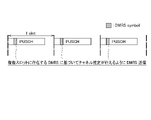
- FIG. 4 is a diagram showing an arrangement example (part 1) of DMRSs used for joint channel estimation.
- FIG. 5 is a diagram showing an arrangement example (part 2) of DMRSs used for joint channel estimation.
- FIG. 6 is a diagram showing an example of UL channel repetition according to operation example 1-1 (Opt 3).
- FIG. 7 is a diagram illustrating an example of UL channel repetition according to operation example 1-1 (Opt 4).
- FIG. 8 is a diagram illustrating an example of UL channel Repetition according to Operation Example 1-2 (Opt 3, 4).
- FIG. 9 is a diagram illustrating an example of UL channel repetition according to operation example 1-2 (Opt 5).
- FIG. 10 is a diagram illustrating an example of UL channel Repetition according to operation example 1-3 (Alt 1, 2).
- FIG. 11 is a diagram illustrating an example of UL channel Repetition according to operation example 1-3 (Alt 3, 4).
- FIG. 12 is a diagram showing an arrangement example (part 1) of PUSCH DMRSs used for joint channel estimation according to operation example 2-1 (Alt 1, 2).
- FIG. 13 is a diagram illustrating an arrangement example of PUCCH DMRSs used for joint channel estimation according to operation example 2-1 (Alt 1).
- FIG. 14 is a diagram illustrating an arrangement example (part 2) of PUSCH DMRSs used for joint channel estimation according to operation example 2-1 (Alt 2).
- FIG. 15 is a diagram illustrating an arrangement example (part 3) of PUSCH DMRSs used for joint channel estimation according to operation example 2-1 (Alt 2).
- FIG. 16 is a diagram illustrating an arrangement example of DMRSs used for joint channel estimation according to operation example 2-2 (Opt 3).
- FIG. 17 is a diagram showing an example of the hardware configuration of gNB100 and UE200.
- FIG. 1 is an overall schematic configuration diagram of a radio communication system 10 according to the present embodiment.
- the radio communication system 10 is a radio communication system according to 5G New Radio (NR), and includes a Next Generation-Radio Access Network 20 (hereinafter NG-RAN 20 and terminals 200 (User Equipment 200, hereinafter UE 200).
- NG-RAN 20 Next Generation-Radio Access Network 20
- UE 200 User Equipment 200
- the wireless communication system 10 may be a wireless communication system according to a system called Beyond 5G, 5G Evolution, or 6G.
- NG-RAN 20 includes a radio base station 100 (hereinafter gNB 100).
- gNB 100 radio base station 100
- the specific configuration of the radio communication system 10 including the number of gNBs and UEs is not limited to the example shown in FIG.
- NG-RAN 20 actually includes multiple NG-RAN Nodes, specifically gNBs (or ng-eNBs), and is connected to a 5G-compliant core network (5GC, not shown). Note that NG-RAN 20 and 5GC may simply be referred to as a "network”.
- gNBs or ng-eNBs
- 5GC 5G-compliant core network
- the gNB100 is an NR-compliant radio base station and performs NR-compliant radio communication with the UE200.
- gNB100 and UE200 control radio signals transmitted from multiple antenna elements to generate beams with higher directivity Massive MIMO, carrier aggregation (CA) that uses multiple component carriers (CC) in a bundle, And dual connectivity (DC) in which communication is performed simultaneously between the UE and multiple NG-RAN Nodes, etc., can be supported.
- Massive MIMO Massive MIMO
- CA carrier aggregation
- CC component carriers
- DC dual connectivity
- the wireless communication system 10 supports FR1 and FR2.
- the frequency bands of each FR are as follows.
- FR1 410MHz to 7.125GHz
- FR2 24.25 GHz to 52.6 GHz
- SCS Sub-Carrier Spacing
- BW bandwidth
- FR2 is a higher frequency than FR1 and may use an SCS of 60 or 120 kHz (240 kHz may be included) and a bandwidth (BW) of 50-400 MHz.
- the wireless communication system 10 may also support a higher frequency band than the FR2 frequency band. Specifically, the wireless communication system 10 may support frequency bands above 52.6 GHz and up to 114.25 GHz.
- Cyclic Prefix-Orthogonal Frequency Division Multiplexing CP-OFDM
- DFT-S-OFDM Discrete Fourier Transform-Spread
- SCS Sub-Carrier Spacing
- DFT-S-OFDM may be applied not only to the uplink (UL) but also to the downlink (DL).
- FIG. 2 shows a configuration example of radio frames, subframes and slots used in the radio communication system 10.
- one slot consists of 14 symbols, and the larger (wider) the SCS, the shorter the symbol period (and slot period). Note that the number of symbols forming one slot does not necessarily have to be 14 symbols (for example, 28 or 56 symbols). Also, the number of slots per subframe may vary depending on the SCS. Additionally, the SCS may be wider than 240kHz (eg, 480kHz, 960kHz, as shown in Figure 2).
- time direction (t) shown in FIG. 2 may also be referred to as the time domain, time domain, symbol period, symbol time, or the like.
- the frequency direction may also be called frequency domain, frequency domain, resource block, resource block group, subcarrier, BWP (Bandwidth part), subchannel, common frequency resource, and the like.
- the radio communication system 10 can support coverage enhancement (CE: Coverage Enhancement) that expands the coverage of cells (or physical channels) formed by the gNB 100.
- Coverage enhancement may provide mechanisms for increasing the success rate of reception of various physical channels.
- gNB 100 can support repeated transmission of PDSCH (Physical Downlink Shared Channel), and UE 200 can support repeated transmission of PUSCH (Physical Uplink Shared Channel).
- PDSCH Physical Downlink Shared Channel
- PUSCH Physical Uplink Shared Channel
- a time division duplex (TDD) slot configuration pattern may be set.
- DDDSU downlink (DL) symbol
- S DL/uplink (UL) or guard symbol
- U UL symbol
- D indicates a slot containing all DL symbols
- S indicates a slot containing a mixture of DL, UL, and guard symbols (G).
- U indicates a slot containing all UL symbols.
- channel estimation of PUSCH can be performed using a demodulation reference signal (DMRS) for each slot.
- DMRS demodulation reference signal
- Such channel estimation may be called joint channel estimation. Alternatively, it may be called by another name such as cross-slot channel estimation.
- the UE 200 can transmit DMRS assigned to (spanning) multiple slots so that the gNB 100 can perform joint channel estimation using DMRS.
- TB processing over multi-slot PUSCH which processes transport blocks (TB) via PUSCHs assigned to multiple slots, may be applied for coverage extension.
- the number of allocated symbols can be the same in each slot, as in Time Domain Resource Allocation (TDRA) of PUSCH Repetition type A (details below), or PUSCH Repetition type B (details below) ), the number of symbols allocated to each slot may be different.
- TDRA Time Domain Resource Allocation
- TDRA may be interpreted as resource allocation in the PUSCH time domain specified in 3GPP TS38.214.
- the PUSCH TDRA may be interpreted as defined by a radio resource control layer (RRC) information element (IE), specifically PDSCH-Config or PDSCH-ConfigCommon.
- RRC radio resource control layer
- TDRA may also be interpreted as resource allocation in the time domain of PUSCH specified by Downlink Control Information (DCI).
- DCI Downlink Control Information
- FIG. 3 is a functional block configuration diagram of gNB100 and UE200.
- the UE 200 includes a radio signal transmission/reception unit 210, an amplifier unit 220, a modem unit 230, a control signal/reference signal processing unit 240, an encoding/decoding unit 250, a data transmission/reception unit 260, and a control unit 270. .
- FIG. 3 shows only main functional blocks related to the description of the embodiment, and that the UE 200 (gNB 100) has other functional blocks (for example, power supply section, etc.). Also, FIG. 3 shows the functional block configuration of the UE 200, and please refer to FIG. 17 for the hardware configuration.
- the radio signal transmitting/receiving unit 210 transmits/receives radio signals according to NR.
- the radio signal transmitting/receiving unit 210 controls radio (RF) signals transmitted from multiple antenna elements to generate beams with higher directivity. It can support aggregation (CA), dual connectivity (DC) in which communication is performed simultaneously between the UE and two NG-RAN Nodes, and the like.
- CA aggregation
- DC dual connectivity
- the radio signal transmitting/receiving unit 210 may transmit a physical uplink shared channel.
- the radio signal transmitting/receiving unit 210 may constitute a transmitting unit.
- the radio signal transmitting/receiving unit 210 may transmit PUSCH toward the network (gNB 100).
- the radio signal transmitting/receiving unit 210 may support repeated transmission (Repetition) of PUSCH.
- Repetition type A may be interpreted as a form in which the PUSCH allocated within the slot is repeatedly transmitted. That is, PUSCH is 14 symbols or less, and there is no possibility of being allocated across multiple slots (adjacent slots).
- Repetition type B may be interpreted as repeated transmission of PUSCH to which 15 or more PUSCH symbols may be allocated. In the present embodiment, allocation of such PUSCH across multiple slots may be allowed.
- the radio signal transmitting/receiving unit 210 may repeatedly transmit an uplink channel (UL channel) in a specific period of a plurality of slots or more.
- the uplink channel may include a physical uplink shared channel (PUSCH) and a physical uplink control channel (PUCCH).
- PUSCH physical uplink shared channel
- PUCCH physical uplink control channel
- a shared channel may also be referred to as a data channel.
- a specific period of multiple slots or more may be interpreted as a period related to PUSCH (or PUCCH) repetition.
- the specific period may be indicated by the number of Repetitions, or may be the time during which a specified number of Repetitions are executed.
- the radio signal transmitting/receiving unit 210 may repeatedly transmit the UL channel a specific number of times. Specifically, radio signal transmitting/receiving section 210 may repeatedly transmit PUSCH (or PUCCH) multiple times.
- the specific period and/or the specific number of times may be indicated by signaling from the network (the upper layer of RRC or the lower layer such as DCI, the same applies hereinafter), or may be preset in the UE 200. .
- the amplifier section 220 is configured by a PA (Power Amplifier)/LNA (Low Noise Amplifier) and the like. Amplifier section 220 amplifies the signal output from modem section 230 to a predetermined power level. In addition, amplifier section 220 amplifies the RF signal output from radio signal transmission/reception section 210 .
- PA Power Amplifier
- LNA Low Noise Amplifier
- the modulation/demodulation unit 230 executes data modulation/demodulation, transmission power setting, resource block allocation, etc. for each predetermined communication destination (gNB 100, etc.).
- the modem unit 230 may apply Cyclic Prefix-Orthogonal Frequency Division Multiplexing (CP-OFDM)/Discrete Fourier Transform-Spread (DFT-S-OFDM). Also, DFT-S-OFDM may be used not only for uplink (UL) but also for downlink (DL).
- the control signal/reference signal processing unit 240 executes processing related to various control signals transmitted and received by the UE 200 and processing related to various reference signals transmitted and received by the UE 200.
- control signal/reference signal processing unit 240 receives various control signals transmitted from the gNB 100 via a predetermined control channel, for example, radio resource control layer (RRC) control signals. Also, the control signal/reference signal processing unit 240 transmits various control signals to the gNB 100 via a predetermined control channel.
- RRC radio resource control layer
- the control signal/reference signal processing unit 240 executes processing using reference signals (RS) such as Demodulation Reference Signal (DMRS) and Phase Tracking Reference Signal (PTRS).
- RS reference signals
- DMRS Demodulation Reference Signal
- PTRS Phase Tracking Reference Signal
- a DMRS is a known reference signal (pilot signal) between a terminal-specific base station and a terminal for estimating the fading channel used for data demodulation.
- PTRS is a terminal-specific reference signal for estimating phase noise, which is a problem in high frequency bands.
- reference signals may include Channel State Information-Reference Signal (CSI-RS), Sounding Reference Signal (SRS), and Positioning Reference Signal (PRS) for position information.
- CSI-RS Channel State Information-Reference Signal
- SRS Sounding Reference Signal
- PRS Positioning Reference Signal
- control channels include PDCCH (Physical Downlink Control Channel), PUCCH (Physical Uplink Control Channel), RACH (Random Access Channel, Downlink Control Information (DCI) including Random Access Radio Network Temporary Identifier (RA-RNTI)), and Physical Broadcast Channel (PBCH) etc. may be included.
- PDCCH Physical Downlink Control Channel
- PUCCH Physical Uplink Control Channel
- RACH Random Access Channel
- DCI Downlink Control Information
- RA-RNTI Random Access Radio Network Temporary Identifier
- PBCH Physical Broadcast Channel
- data channels include PDSCH (Physical Downlink Shared Channel) and PUSCH (Physical Uplink Shared Channel).
- Data may refer to data transmitted over a data channel.
- control signal/reference signal processing unit 240 may transmit the capability information of the UE 200 regarding allocation of the physical uplink shared channel (PUSCH) to the network.
- the control signal/reference signal processing unit 240 may configure a transmitting unit that transmits capability information.
- control signal/reference signal processing unit 240 can transmit UE Capability Information related to PUSCH allocation (which may include repetition) to the gNB 100. Details of UE Capability Information will be described later.
- the encoding/decoding unit 250 performs data segmentation/concatenation, channel coding/decoding, etc. for each predetermined communication destination (gNB 100 or other gNB).
- the encoding/decoding unit 250 divides the data output from the data transmission/reception unit 260 into pieces of a predetermined size, and performs channel coding on the divided data. Also, encoding/decoding section 250 decodes the data output from modem section 230 and concatenates the decoded data.
- the data transmission/reception unit 260 executes transmission/reception of Protocol Data Unit (PDU) and Service Data Unit (SDU). Specifically, the data transmitting/receiving unit 260 performs PDU/SDU in multiple layers (medium access control layer (MAC), radio link control layer (RLC), packet data convergence protocol layer (PDCP), etc.). Assemble/disassemble etc. The data transmission/reception unit 260 also performs data error correction and retransmission control based on hybrid ARQ (Hybrid automatic repeat request).
- hybrid ARQ Hybrid automatic repeat request
- the control unit 270 controls each functional block that configures the UE200.
- the control unit 270 controls transmission of UL channels, specifically PUSCH and PUCCH.
- control unit 270 can hop the UL channel in the frequency direction in units of a specific period of more than a plurality of slots. Hopping in the frequency direction of the UL channel may be called frequency hopping, and frequency hopping in units of a specific period of multiple slots or more may be called inter-slot frequency hopping. . Note that hopping may mean that the frequency resource to be used changes. In short, it may mean that the subcarrier, resource block, resource block group, BWP, etc. are changed.
- control unit 270 may cause the UL channel to hop in the frequency direction in units of a specific number of times indicating the number of repeated transmissions of the UL channel. Specifically, the control unit 270 may perform frequency hopping in units of the number of repeated transmissions (repetition number) of the designated UL channel, in other words, every predetermined number of repetitions.
- the control unit 270 if the transmission of the UL channel (PUSCH and PUCCH) overlaps (may be expressed as a case of collision), the UL channel (Repetition may be )
- the UL channel (Repetition may be )
- a frequency hopping pattern using allocatable resources that avoids duplication may be determined.
- the control unit 270 can assign avoiding overlap at the first Repetition of the UL channel, specifically at the transmission timing of the first Repetition.
- a hopping pattern using resources may be determined.
- control unit 270 may set a hopping pattern related to UL channel repetition as described above, based on signaling from the network.
- the control unit 270 may determine the allocation of DMRS transmitted on the UL channel, specifically the PUSCH, based on the PUSCH repetition state, that is, the number of repetitions, the repetition period, and the like.
- control unit 270 may transmit the same DMRS symbol (OFDM symbol) for each predetermined number of repetitions. Also, the control unit 270 may set a DMRS symbol (OFDM symbol) to be used for each predetermined number of repetitions.
- OFDM symbol DMRS symbol
- the gNB 100 may also be provided with the functions related to DMRS transmission/reception and control described above.
- the gNB 100 (radio signal transmitting/receiving unit 210) may configure a receiving unit that receives UL channels repeatedly transmitted from the UE 200 within a specific period.
- the radio signal transmitting/receiving unit 210 of the gNB 100 may receive the UL channel hopped in the frequency direction in units of the specific period.
- the gNB 100 may receive from the UE 200 a specific number of repeated transmissions, that is, a UL channel (for example, PUSCH) on which Repetition is performed.
- the gNB 100 may receive the UL channel hopped in the frequency direction in units of the specific number of times.
- the gNB 100 configures a control unit that performs channel estimation (Joint channel estimation) of UL channels allocated to multiple slots, for example PUSCH, using DMRS allocated to multiple slots. good.
- the gNB 100 may perform joint channel estimation of UL channels (for example, PUSCH) allocated to the multiple slots using DMRS allocated to the multiple slots.
- UL channels for example, PUSCH
- the gNB 100 uses the DMRS assigned to multiple slots, the initial access of the UE 200, specifically, the UL channel in the random access procedure (Joint channel estimation) may be performed. .
- joint channel estimation may be interpreted as a technique of performing channel estimation based on (assigned) DMRS present in multiple slots.
- Fig. 4 shows a DMRS arrangement example (part 1) used for joint channel estimation.
- the UE 200 may transmit DMRS symbols between specific PUSCHs, between PUCCHs, or between PUSCHs and PUCCHs so that the gNB 100 can perform joint channel estimation.
- the UE 200 may transmit DMRS symbols whose transmission power and phase do not change between slots.
- Fig. 5 shows an arrangement example (2) of DMRS used for joint channel estimation.
- UE 200 may determine resources to be used for DMRS transmission by any of the following methods.
- DMRSs When using individual DMRS allocation DMRSs may be allocated to DMRS resources allocated to each PUSCH before the PUSCHs are integrated.
- Operation example 1 (3.3.1) Operation example 1-1
- operations related to frequency hopping (Type A repetition like TDRA and PUCCH) will be described.
- the UE 200 may determine the hopping pattern of the UL channel from among the following hopping patterns according to rules (settings) specified by the network (radio base station) or defined in advance.
- the UL channel may mean either PUSCH or PUCCH (same below).
- the UL channel may include repeated PUSCH or PUCCH.
- the UE 200 may determine any of the following hopping patterns when applying Type A repetition-like TDRA or using PUCCH.
- the number of slots may be the number of slots actually allocated by Repetition, or the number of slots before the Repetition resource is dropped.
- Fig. 6 shows an example of UL channel repetition according to operation example 1-1 (Opt 3).
- each frame in the time (t) direction may be interpreted as corresponding to a slot (although it may be a symbol or the like) (same below).
- hop duration may be expressed in terms such as duration hop, hopping duration, duration per hop, etc., and may be indicated by the length of time or the number of repetitions.
- (Opt 4): frequency hopping every X slots (Opt 4-1): Duration per hop is notified from the network For example, it is notified that duration per hop X number of slots, and frequency hopping may be performed for each X slot.
- the time window size may be a time domain to which joint channel estimation is applicable, may be a slot unit, or may be another time domain unit such as a symbol (hereinafter the same).
- Operation example 1-2 In this operation example, operations related to frequency hopping (Type B repetition like TDRA) will be described.
- the UE 200 may determine the hopping pattern of the UL channel from among the following hopping patterns according to rules specified by the network (radio base station) or defined in advance.
- the UE 200 may determine any of the following hopping patterns.
- FIG. 8 shows an example of UL channel repetition according to operation example 1-2 (Opt 3, 4). Specifically, the upper side of FIG. 8 shows an example of UL channel repetition for Opt 3, and the lower side of FIG. 8 shows an example of UL channel repetition for Opt 4.
- ⁇ (Opt 5): Frequency hopping every X Repetition (Opt 5-1): Duration per hop is notified from the network For example, the UE 200 may notify duration per hop X number of repetitions, and perform frequency hopping every X repetitions.
- Fig. 9 shows an example of UL channel repetition according to operation example 1-2 (Opt 5).
- frequency hopping may be performed every three slots.
- the hopping timing may be within a slot (in the middle) instead of at the slot boundary.
- FIG. 10 shows an example of UL channel repetition according to operation example 1-3 (Alt 1, 2).
- Joint channel estimation is applied (on the radio base station side) to UE 200, and repetition resources of UL channels (eg, PUSCH) collide with different resources (eg, resources for PUCCH) (which may be called overlap). If so, one of the following hopping patterns may apply:
- the hopping pattern may be applied on a slot-by-slot basis without considering the case where resources are dropped. For example, a similar hopping pattern may be maintained even if the Repetition resource is dropped a second time (see upper part of FIG. 10, the dropped Repetition resource is indicated by the dotted line frame).
- a hopping pattern may be applied based on resources used for transmission of each repetition. For example, if the second Repetition resource is dropped, the hopping pattern may be applied except for the dropped resource (see the bottom of FIG. 10, since the dropped Repetition resource (dotted frame) is excluded, the slot The resources in the frequency direction after #3 are different from Alt. 1).
- Alt 1 and 2 may be set separately when a hopping pattern as described later is applied, or when the number of repeated transmissions is specified based on the number of allocatable resources.
- FIG. 11 shows an example of UL channel Repetition according to operation example 1-3 (Alt 3, 4).
- allocatable resources may be determined according to the reason for collision. For example, symbols of TDD pattern, SS/PBCH block (Synchronization Signal/Physical Broadcast Channel blocks) may be considered, but collision with repeated transmission of SFI (Slot Format Indication)/CI (Cancel Indication)/PUCCH is not considered. may be assumed. Alternatively, the drop of Repetition resources known to the radio base station (gNB 100) may be considered, but the drop that the radio base station cannot determine may not be considered.
- allocatable resources may be determined according to the reason for time collision. Similar to Alt 3, for example, symbols of TDD pattern and SS/PBCH block may be considered, but collision with repeated transmission of SFI/CI/PUCCH may not be considered.
- the drop of Repetition resources known to the radio base station may be considered, but the drop that the radio base station cannot determine may not be considered.
- the UE 200 may operate as follows.
- the UE 200 may determine the following behavior during frequency hopping.
- ⁇ hopping pattern to select - Behavior when a drop occurs when frequency hopping is applied Such behavior can be determined using higher layer (for example, RRC, the same shall apply hereinafter) signaling, or according to predefined rules (settings). good.
- the UE 200 may set the hopping pattern by any of the following methods.
- the UE 200 may apply any of the following methods.
- ⁇ (Alt 1) Set different hopping patterns for when joint channel estimation is applied and when not applied
- ⁇ (Alt 2) Set a common hopping pattern for when joint channel estimation is applied and when not applied do
- Operation example 1-4-1 the UE 200 may determine the above-described behavior during frequency hopping based on the following information regarding PUSCH repetition frequency hopping.
- DCI - (Opt 1-1) Explicit frequency hopping-related information by DCI field
- higher-layer signaling is used to link (associate) the frequency hopping-related information with the DCI field.
- a predefined rule (setting) may be followed.
- frequency hopping-related information information elements Add frequency hopping-related information information elements to the TDRA table in the upper layer, determined by DCI (Opt 1-3): Implicit frequency hopping-related information by DCI fields
- the DCI field may be associated with frequency hopping-related information.
- frequency hopping-related information may be associated with a CCE (Control channel element) index in which a DCI for resource allocation is allocated.
- CCE Control channel element
- a hopping pattern may be selected based on frequency hopping-related information received in RRC.
- Operation example 1-4-2 the UE 200 may determine the above-described behavior during frequency hopping based on the following information regarding PUCCH repetition frequency hopping.
- frequency hopping-related information may be associated with the PUCCH resource indicator.
- frequency hopping-related information may be associated with a CCE index in which a DCI for resource allocation is arranged.
- the linking method may be notified by upper layer signaling, or may be determined by a predetermined rule.
- ⁇ (Opt 2) MAC CE (Control Element)
- ⁇ (Opt 3) Upper layer signal
- ⁇ (Opt 4) Determine hopping pattern based on predetermined rules good.
- the UE 200 may determine resources to be used for DMRS transmission based on any of the following methods.
- the UE 200 may determine the number of OFDM symbols to use for DMRS during repeated transmission based on any of the following methods. Note that this method may be applied when the same number of OFDM symbols for DMRS is transmitted every X repetitions (X repetition).
- ⁇ (Alt 1) Determine whether or not to transmit (or not transmit) DMRS every X repetitions
- ⁇ (Alt 2) Determine the number of DMRS OFDM symbols to be used every X repetitions In this case, the value of X is It can be any number from "1" to the total number of repeated transmissions. Repetition may be read as slot (same below).
- FIG. 12 shows an arrangement example (part 1) of PUSCH DMRS used for joint channel estimation according to operation example 2-1 (Alt 1, 2).
- the number of DMRS OFDM symbols may be determined (Alt 1), or the number of DMRS OFDM symbols is determined (Alt 2) for each repetition (unit) of PUSCH. good too.
- the UE 200 may determine whether or not to set Repetition that does not transmit DMRS, based on a predetermined rule, DCI, MAC CE, or RRC.
- the presence or absence of DMRS transmission during PUSCH transmission may be determined as follows.
- whether or not to transmit DMRS during PUCCH transmission may be determined as follows.
- the UE 200 may determine how many repetitions DMRS is to be transmitted (or not to be transmitted) based on a predetermined rule, DCI, MAC CE, or RRC.
- FIG. 13 shows an arrangement example of PUCCH DMRS used for joint channel estimation according to operation example 2-1 (Alt 1). Specifically, FIG. 13 shows an example in which DMRS is transmitted every two slots in the case of PUCCH Format 3,4. PF3, 4 is called a long format, and may have 4 to 14 symbols.
- the UE 200 may determine how many repetitions the same number of DMRS OFDM symbols should be transmitted based on a predetermined rule, higher layer signaling, or DCI. In this case, the UE 200 may operate as follows.
- multiple DMRS OFDM symbols separately and refer to them every X repetitions
- multiple DMRS configurations may be set and the UE 200 may apply them every X repetitions.
- the ratio of the number of DMRSOFDM symbols for each repetition to the number of DMRS OFDM symbols set by RRC may be determined.
- the UE 200 is notified from the network (gNB 100), based on the Pattern index (0, 1, 2) associated with the pattern of the number of DMRS OFDM symbols, the number of DMRS OFDM symbols in PUSCH
- the Pattern index (0, 1, 2) associated with the pattern of the number of DMRS OFDM symbols
- the number of DMRS OFDM symbols in PUSCH An example of determining placement is shown. More specifically, FIG. 15 shows an example in which Pattern index 2 is notified and two DMRS OFDM symbols are sequentially arranged in slots, one after another.
- the UE 200 may determine OFDM symbol positions for DMRS when joint channel estimation is applied, based on any of the following methods.
- (Opt 2) Determining DMRS OFDM symbol positions based on resources in multiple slots For example, DMRSs may be transmitted evenly in two slots.
- (Opt 3) Determine DMRS OFDM symbol positions based on resources to which joint channel estimation is applied. In some cases, the other operation examples described above may be combined. Also, the UE 200 may determine the DMRS OFDM symbol position based on a predetermined rule, higher layer signaling, or DCI.
- FIG. 16 shows an example of DMRS arrangement used for joint channel estimation according to operation example 2-2 (Opt 3). As shown in FIG. 16, similar DMRS OFDM symbol positions may be assigned according to the range to which joint channel estimation is applied (Rep #0-2, Rep #3-5).
- the UE 200 may receive joint channel estimation for Msg3initial transmission related information based on any of the following methods or combinations. In this case, settings related to joint channel estimation may differ depending on the frequency (band) used by the UE.
- PUSCH-ConfigCommon IE Information Element
- RACH-ConfigCommon IE defined in the RRC layer
- Msg3 is a random access channel (RACH) procedure message
- PUSCH may be used to transmit Msg3.
- Msg1 may be transmitted via PRACH (Physical Random Access Channel). Msg1 may be called PRACH Preamble. Msg2 may be transmitted via PDSCH. Msg2 may be called RAR (Random Access Response). Msg3 may be called RRC Connection Request. Msg4 may be called RRC Connection Setup.
- PRACH Physical Random Access Channel
- Msg1 may be called PRACH Preamble.
- Msg2 may be transmitted via PDSCH.
- Msg2 may be called RAR (Random Access Response).
- Msg3 may be called RRC Connection Request.
- Msg4 may be called RRC Connection Setup.
- Enhanced UE is notified by transmitting a RAR with a MAC configuration different from that of a normal UE
- Enhanced UE may mean a UE that supports joint channel estimation.
- Alt 2 Notification using TDRA of UL grant (grant) For example, add an information element related to channel estimation across multiple slots to the TDRA table set in RRC, the information is selected by DCI you can
- Implicit notification using UL grant information For example, it may be linked to a TPC (Transmit Power Control) command or MCS (Modulation and Coding Scheme).
- the linking method may be set according to a predetermined rule or network (radio base station).
- related information may be linked to TDRA, TPC command or MCS.
- the linking method may be set according to a predetermined rule or network (radio base station).
- RNTI for DCI with CRC scrambled by Enhanced UE may be used.
- RNTI for Enhanced UE may be assigned by RAR.
- Joint channel estimation-related information may also be notified by DCI for Enhanced UE.
- the UE 200 may report (notify) to the network (radio base station) whether or not to apply joint channel estimation when transmitting Msg3, or whether to apply joint channel estimation, based on any of the following methods.
- ⁇ (Opt 2) Report independently of the applicability (or request) of repeated transmission of Msg3 ⁇ (Opt 2-1): Assign a different initial bandwidth depending on the applicability (or request) ⁇ (Opt 2 -2): Use different RACH preambles depending on applicability (or requirements) - (Opt 2-3): Use different RACH occasions depending on applicability (or requirements) - (Opt 2-4): Use a specific OCC (Orthogonal Cover Code) pattern in Msg1, which is repeated as applicable (or requested)
- OCC Orthogonal Cover Code
- the UE 200 may report the following contents as UE Capability Information to the network regarding joint channel estimation.
- the target may be the PUSCH and PUCCH collectively or individually.
- the UE 200 may report the corresponding (supported) frequency (FR or band) by any of the following methods.
- the UE 200 may report the supported duplexing scheme by any of the following methods.
- demodulation reference signals used for channel estimation of PUSCH (or PUCCH) have been described, but reference signals used for channel estimation of physical channels such as PUSCH (or PUCCH) For example, other reference signals may be used.
- configure, activate, update, indicate, enable, specify, and select may be read interchangeably. good.
- link, associate, correspond, and map may be read interchangeably to allocate, assign, monitor. , map, may also be read interchangeably.
- each functional block may be implemented using one device physically or logically coupled, or directly or indirectly using two or more physically or logically separate devices (e.g. , wired, wireless, etc.) and may be implemented using these multiple devices.
- a functional block may be implemented by combining software in the one device or the plurality of devices.
- Functions include judging, determining, determining, calculating, calculating, processing, deriving, investigating, searching, checking, receiving, transmitting, outputting, accessing, resolving, selecting, choosing, establishing, comparing, assuming, expecting, assuming, Broadcasting, notifying, communicating, forwarding, configuring, reconfiguring, allocating, mapping, assigning, etc. can't
- a functional block (component) that performs transmission is called a transmitting unit or transmitter.
- the implementation method is not particularly limited.
- FIG. 17 is a diagram showing an example of the hardware configuration of the device.
- the device may be configured as a computer device including a processor 1001, a memory 1002, a storage 1003, a communication device 1004, an input device 1005, an output device 1006, a bus 1007, and the like.
- the term "apparatus” can be read as a circuit, device, unit, or the like.
- the hardware configuration of the device may be configured to include one or more of each device shown in the figure, or may be configured without some of the devices.
- Each functional block of the device (see FIG. 3) is realized by any hardware element of the computer device or a combination of the hardware elements.
- each function of the device is implemented by causing the processor 1001 to perform calculations, controlling communication by the communication device 1004, and controlling the It is realized by controlling at least one of data reading and writing in 1002 and storage 1003 .
- a processor 1001 operates an operating system and controls the entire computer.
- the processor 1001 may be configured by a central processing unit (CPU) including interfaces with peripheral devices, a control unit, an arithmetic unit, registers, and the like.
- CPU central processing unit
- the processor 1001 reads programs (program codes), software modules, data, etc. from at least one of the storage 1003 and the communication device 1004 to the memory 1002, and executes various processes according to them.
- programs program codes
- software modules software modules
- data etc.
- the various processes described above may be executed by one processor 1001, or may be executed by two or more processors 1001 simultaneously or sequentially.
- Processor 1001 may be implemented by one or more chips. Note that the program may be transmitted from a network via an electric communication line.
- the memory 1002 is a computer-readable recording medium, and is composed of at least one of Read Only Memory (ROM), Erasable Programmable ROM (EPROM), Electrically Erasable Programmable ROM (EEPROM), Random Access Memory (RAM), etc. may be
- ROM Read Only Memory
- EPROM Erasable Programmable ROM
- EEPROM Electrically Erasable Programmable ROM
- RAM Random Access Memory
- the memory 1002 may also be called a register, cache, main memory (main storage device), or the like.
- the memory 1002 can store programs (program code), software modules, etc. capable of executing a method according to an embodiment of the present disclosure.
- the storage 1003 is a computer-readable recording medium, for example, an optical disc such as a Compact Disc ROM (CD-ROM), a hard disk drive, a flexible disc, a magneto-optical disc (for example, a compact disc, a digital versatile disc, a Blu-ray disk), smart card, flash memory (eg, card, stick, key drive), floppy disk, magnetic strip, and/or the like.
- Storage 1003 may also be referred to as an auxiliary storage device.
- the recording medium described above may be, for example, a database, server, or other suitable medium including at least one of memory 1002 and storage 1003 .
- the communication device 1004 is hardware (transmitting/receiving device) for communicating between computers via at least one of a wired network and a wireless network, and is also called a network device, a network controller, a network card, a communication module, or the like.
- the communication device 1004 includes a high-frequency switch, duplexer, filter, frequency synthesizer, etc., for realizing at least one of frequency division duplex (FDD) and time division duplex (TDD).
- FDD frequency division duplex
- TDD time division duplex
- the input device 1005 is an input device (for example, keyboard, mouse, microphone, switch, button, sensor, etc.) that receives input from the outside.
- the output device 1006 is an output device (eg, display, speaker, LED lamp, etc.) that outputs to the outside. Note that the input device 1005 and the output device 1006 may be integrated (for example, a touch panel).
- each device such as the processor 1001 and the memory 1002 is connected by a bus 1007 for communicating information.
- the bus 1007 may be configured using a single bus, or may be configured using different buses between devices.
- the device includes hardware such as a microprocessor, digital signal processor (DSP), application specific integrated circuit (ASIC), programmable logic device (PLD), field programmable gate array (FPGA), etc.
- DSP digital signal processor
- ASIC application specific integrated circuit
- PLD programmable logic device
- FPGA field programmable gate array
- notification of information is not limited to the aspects/embodiments described in the present disclosure, and may be performed using other methods.
- the notification of information may include physical layer signaling (e.g., Downlink Control Information (DCI), Uplink Control Information (UCI), higher layer signaling (e.g., RRC signaling, Medium Access Control (MAC) signaling, broadcast information (Master Information Block (MIB), System Information Block (SIB), other signals, or combinations thereof, and RRC signaling may also be referred to as RRC messages, e.g., RRC Connection Setup ) message, RRC Connection Reconfiguration message, or the like.
- DCI Downlink Control Information
- UCI Uplink Control Information
- RRC signaling e.g., RRC signaling, Medium Access Control (MAC) signaling, broadcast information (Master Information Block (MIB), System Information Block (SIB), other signals, or combinations thereof
- RRC signaling may also be referred to as RRC messages, e.g., RRC Connection Setup ) message, R
- LTE Long Term Evolution
- LTE-A LTE-Advanced
- SUPER 3G IMT-Advanced
- 4G 4th generation mobile communication system
- 5G 5th generation mobile communication system
- Future Radio Access FAA
- New Radio NR
- W-CDMA registered trademark
- GSM registered trademark
- CDMA2000 Code Division Multiple Access 2000
- UMB Ultra Mobile Broadband
- IEEE 802.11 Wi-Fi (registered trademark)
- IEEE 802.16 WiMAX®
- IEEE 802.20 Ultra-WideBand (UWB), Bluetooth®, other suitable systems, and/or next-generation systems enhanced therefrom.
- a plurality of systems may be applied in combination (for example, a combination of at least one of LTE and LTE-A and 5G).
- a specific operation that is performed by a base station in the present disclosure may be performed by its upper node in some cases.
- various operations performed for communication with a terminal may be performed by the base station and other network nodes other than the base station (e.g. MME or S-GW, etc., but not limited to).
- MME or S-GW network nodes
- the case where there is one network node other than the base station is exemplified above, it may be a combination of a plurality of other network nodes (for example, MME and S-GW).
- Information, signals can be output from a higher layer (or a lower layer) to a lower layer (or a higher layer). It may be input and output via multiple network nodes.
- Input/output information may be stored in a specific location (for example, memory) or managed using a management table. Input and output information may be overwritten, updated, or appended. The output information may be deleted. The entered information may be transmitted to other devices.
- the determination may be made by a value represented by one bit (0 or 1), by a true/false value (Boolean: true or false), or by numerical comparison (for example, a predetermined value).
- notification of predetermined information is not limited to being performed explicitly, but may be performed implicitly (for example, not notifying the predetermined information). good too.
- Software whether referred to as software, firmware, middleware, microcode, hardware description language or otherwise, includes instructions, instruction sets, code, code segments, program code, programs, subprograms, and software modules. , applications, software applications, software packages, routines, subroutines, objects, executables, threads of execution, procedures, functions, and the like.
- software, instructions, information, etc. may be transmitted and received via a transmission medium.
- the Software uses wired technology (coaxial cable, fiber optic cable, twisted pair, Digital Subscriber Line (DSL), etc.) and/or wireless technology (infrared, microwave, etc.) to access websites, Wired and/or wireless technologies are included within the definition of transmission medium when sent from a server or other remote source.
- wired technology coaxial cable, fiber optic cable, twisted pair, Digital Subscriber Line (DSL), etc.
- wireless technology infrared, microwave, etc.
- data, instructions, commands, information, signals, bits, symbols, chips, etc. may refer to voltages, currents, electromagnetic waves, magnetic fields or magnetic particles, light fields or photons, or any of these. may be represented by a combination of
- the channel and/or symbols may be signaling.
- a signal may also be a message.
- a component carrier may also be called a carrier frequency, a cell, a frequency carrier, or the like.
- system and “network” used in this disclosure are used interchangeably.
- information, parameters, etc. described in the present disclosure may be expressed using absolute values, may be expressed using relative values from a predetermined value, or may be expressed using other corresponding information.
- radio resources may be indexed.
- base station BS
- radio base station fixed station
- NodeB NodeB
- eNodeB eNodeB
- gNodeB gNodeB
- a base station may also be referred to by terms such as macrocell, small cell, femtocell, picocell, and the like.
- a base station can accommodate one or more (eg, three) cells (also called sectors). When a base station accommodates multiple cells, the overall coverage area of the base station can be partitioned into multiple smaller areas, each smaller area corresponding to a base station subsystem (e.g., a small indoor base station (Remote Radio)). Head: RRH) can also provide communication services.
- a base station subsystem e.g., a small indoor base station (Remote Radio)
- Head: RRH can also provide communication services.
- cell refers to part or all of the coverage area of at least one of a base station and base station subsystem that provides communication services in this coverage.
- MS Mobile Station
- UE User Equipment
- a mobile station is defined by those skilled in the art as a subscriber station, mobile unit, subscriber unit, wireless unit, remote unit, mobile device, wireless device, wireless communication device, remote device, mobile subscriber station, access terminal, mobile terminal, wireless It may also be called a terminal, remote terminal, handset, user agent, mobile client, client, or some other suitable term.
- At least one of the base station and mobile station may be called a transmitting device, a receiving device, a communication device, or the like.
- At least one of the base station and the mobile station may be a device mounted on a mobile object, the mobile object itself, or the like.
- the mobile body may be a vehicle (e.g., car, airplane, etc.), an unmanned mobile body (e.g., drone, self-driving car, etc.), or a robot (manned or unmanned ).
- at least one of the base station and the mobile station includes devices that do not necessarily move during communication operations.
- at least one of the base station and mobile station may be an Internet of Things (IoT) device such as a sensor.
- IoT Internet of Things
- the base station in the present disclosure may be read as a mobile station (user terminal, hereinafter the same).
- communication between a base station and a mobile station is replaced with communication between multiple mobile stations (for example, Device-to-Device (D2D), Vehicle-to-Everything (V2X), etc.)
- the mobile station may have the functions that the base station has.
- words such as "up” and “down” may be replaced with words corresponding to inter-terminal communication (for example, "side”).
- uplink channels, downlink channels, etc. may be read as side channels.
- a radio frame may consist of one or more frames in the time domain. Each frame or frames in the time domain may be referred to as a subframe. A subframe may also consist of one or more slots in the time domain. A subframe may be a fixed time length (eg, 1 ms) independent of numerology.
- a numerology may be a communication parameter that applies to the transmission and/or reception of a signal or channel. Numerology, for example, subcarrier spacing (SCS), bandwidth, symbol length, cyclic prefix length, transmission time interval (TTI), number of symbols per TTI, radio frame structure, transmission and reception specific filtering operations performed by the receiver in the frequency domain, specific windowing operations performed by the transceiver in the time domain, and/or the like.
- SCS subcarrier spacing
- TTI transmission time interval
- number of symbols per TTI radio frame structure
- transmission and reception specific filtering operations performed by the receiver in the frequency domain specific windowing operations performed by the transceiver in the time domain, and/or the like.
- a slot may consist of one or more symbols (Orthogonal Frequency Division Multiplexing (OFDM) symbols, Single Carrier Frequency Division Multiple Access (SC-FDMA) symbols, etc.) in the time domain.
- OFDM Orthogonal Frequency Division Multiplexing
- SC-FDMA Single Carrier Frequency Division Multiple Access
- a slot may be a unit of time based on numerology.
- a slot may contain multiple mini-slots. Each minislot may consist of one or more symbols in the time domain. A minislot may also be referred to as a subslot. A minislot may consist of fewer symbols than a slot.
- a PDSCH (or PUSCH) that is transmitted in time units larger than a minislot may be referred to as PDSCH (or PUSCH) mapping type A.
- PDSCH (or PUSCH) transmitted using minislots may be referred to as PDSCH (or PUSCH) mapping type B.
- Radio frames, subframes, slots, minislots and symbols all represent time units when transmitting signals. Radio frames, subframes, slots, minislots and symbols may be referred to by other corresponding designations.
- one subframe may be called a transmission time interval (TTI)
- TTI transmission time interval
- multiple consecutive subframes may be called a TTI
- one slot or one minislot may be called a TTI. That is, at least one of the subframe and TTI may be a subframe (1ms) in existing LTE, may be a period shorter than 1ms (eg, 1-13 symbols), or a period longer than 1ms may be Note that the unit representing the TTI may be called a slot, minislot, or the like instead of a subframe.
- TTI refers to, for example, the minimum scheduling time unit in wireless communication.
- a base station performs scheduling to allocate radio resources (frequency bandwidth, transmission power, etc. that can be used by each user terminal) to each user terminal on a TTI basis.
- radio resources frequency bandwidth, transmission power, etc. that can be used by each user terminal
- the TTI may be a transmission time unit for channel-encoded data packets (transport blocks), code blocks, codewords, etc., or may be a processing unit for scheduling, link adaptation, etc. Note that when a TTI is given, the time interval (for example, the number of symbols) in which transport blocks, code blocks, codewords, etc. are actually mapped may be shorter than the TTI.
- one slot or one minislot is called a TTI
- one or more TTIs may be the minimum scheduling time unit.
- the number of slots (the number of mini-slots) constituting the minimum time unit of the scheduling may be controlled.
- a TTI with a time length of 1 ms may be called a normal TTI (TTI in LTE Rel.8-12), normal TTI, long TTI, normal subframe, normal subframe, long subframe, slot, etc.
- TTI that is shorter than a regular TTI may also be called a shortened TTI, a short TTI, a partial or fractional TTI, a shortened subframe, a short subframe, a minislot, a subslot, a slot, and so on.
- long TTI for example, normal TTI, subframe, etc.
- short TTI for example, shortened TTI, etc.
- a TTI having a TTI length greater than or equal to this value may be read as a replacement.
- a resource block is a resource allocation unit in the time domain and frequency domain, and may include one or more consecutive subcarriers in the frequency domain.
- the number of subcarriers included in an RB may be the same regardless of neurology, and may be 12, for example.
- the number of subcarriers included in an RB may be determined based on neumerology.
- the time domain of an RB may include one or more symbols and may be 1 slot, 1 minislot, 1 subframe, or 1 TTI long.
- One TTI, one subframe, etc. may each consist of one or more resource blocks.
- One or more RBs are physical resource blocks (Physical RB: PRB), sub-carrier groups (SCG), resource element groups (REG), PRB pairs, RB pairs, etc. may be called.
- PRB Physical resource blocks
- SCG sub-carrier groups
- REG resource element groups
- PRB pairs RB pairs, etc.
- a resource block may be composed of one or more resource elements (Resource Element: RE).
- RE resource elements
- 1 RE may be a radio resource region of 1 subcarrier and 1 symbol.
- a Bandwidth Part (which may also be called a Bandwidth Part) represents a subset of contiguous common resource blocks (RBs) for a neumerology in a carrier. good.
- the common RB may be identified by an RB index based on the common reference point of the carrier.
- PRBs may be defined in a BWP and numbered within that BWP.
- BWP may include BWP for UL (UL BWP) and BWP for DL (DL BWP).
- BWP may include BWP for UL (UL BWP) and BWP for DL (DL BWP).
- One or more BWPs may be configured in one carrier for a UE.
- At least one of the configured BWPs may be active, and the UE may not expect to transmit or receive a given signal/channel outside the active BWP.
- BWP bitmap
- radio frames, subframes, slots, minislots and symbols described above are only examples.
- the number of subframes included in a radio frame the number of slots per subframe or radio frame, the number of minislots included in a slot, the number of symbols and RBs included in a slot or minislot, the number of Configurations such as the number of subcarriers and the number of symbols in a TTI, symbol length, cyclic prefix (CP) length, etc.
- CP cyclic prefix
- connection means any direct or indirect connection or coupling between two or more elements, It can include the presence of one or more intermediate elements between two elements being “connected” or “coupled.” Couplings or connections between elements may be physical, logical, or a combination thereof. For example, “connection” may be read as "access”.
- two elements are defined using at least one of one or more wires, cables and printed electrical connections and, as some non-limiting and non-exhaustive examples, in the radio frequency domain. , electromagnetic energy having wavelengths in the microwave and light (both visible and invisible) regions, and the like.
- the reference signal can also be abbreviated as Reference Signal (RS), and may also be called Pilot depending on the applicable standard.
- RS Reference Signal
- any reference to elements using the "first,” “second,” etc. designations used in this disclosure does not generally limit the quantity or order of those elements. These designations may be used in this disclosure as a convenient method of distinguishing between two or more elements. Thus, references to first and second elements do not imply that only two elements may be employed therein or that the first element must precede the second element in any way.
- determining and “determining” used in this disclosure may encompass a wide variety of actions.
- “Judgement” and “determination” are, for example, judging, calculating, computing, processing, deriving, investigating, looking up, searching, inquiring (eg, lookup in a table, database, or other data structure), ascertaining as “judged” or “determined”, and the like.
- "judgment” and “determination” are used for receiving (e.g., receiving information), transmitting (e.g., transmitting information), input, output, access (accessing) (for example, accessing data in memory) may include deeming that a "judgment” or “decision” has been made.
- judgment and “decision” are considered to be “judgment” and “decision” by resolving, selecting, choosing, establishing, comparing, etc. can contain.
- judgment and “decision” may include considering that some action is “judgment” and “decision”.
- judgment (decision) may be read as “assuming”, “expecting”, “considering”, or the like.
- a and B are different may mean “A and B are different from each other.”
- the term may also mean that "A and B are different from C”.
- Terms such as “separate,” “coupled,” etc. may also be interpreted in the same manner as “different.”
- Radio communication system 20 NG-RAN 100 gNB 200UE 210 radio signal transmission/reception unit 220 amplifier unit 230 modulation/demodulation unit 240 control signal/reference signal processing unit 250 encoding/decoding unit 260 data transmission/reception unit 270 control unit 1001 processor 1002 memory 1003 storage 1004 communication device 1005 input device 1006 output device 1007 bus
Abstract
Description
図1は、本実施形態に係る無線通信システム10の全体概略構成図である。無線通信システム10は、5G New Radio(NR)に従った無線通信システムであり、Next Generation-Radio Access Network 20(以下、NG-RAN20、及び端末200(User Equipment 200、以下、UE200)を含む。 (1) Overall Schematic Configuration of Radio Communication System FIG. 1 is an overall schematic configuration diagram of a
・FR2:24.25 GHz~52.6 GHz
FR1では、15, 30または60kHzのSub-Carrier Spacing(SCS)が用いられ、5~100MHzの帯域幅(BW)が用いられてもよい。FR2は、FR1よりも高周波数であり、60または120kHz(240kHzが含まれてもよい)のSCSが用いられ、50~400MHzの帯域幅(BW)が用いられてもよい。 ・FR1: 410MHz to 7.125GHz
・FR2: 24.25 GHz to 52.6 GHz
In FR1, a Sub-Carrier Spacing (SCS) of 15, 30 or 60 kHz may be used and a bandwidth (BW) of 5-100 MHz may be used. FR2 is a higher frequency than FR1 and may use an SCS of 60 or 120 kHz (240 kHz may be included) and a bandwidth (BW) of 50-400 MHz.
次に、無線通信システム10の機能ブロック構成について説明する。具体的には、UE200の機能ブロック構成について説明する。図3は、gNB100及びUE200の機能ブロック構成図である。 (2) Functional Block Configuration of Radio Communication System Next, the functional block configuration of the
次に、無線通信システム10の動作について説明する。具体的には、カバレッジ拡張の性能(coverage performance)を目的とした上りリンクチャネルのチャネル推定に関する動作について説明する。 (3) Operation of Radio Communication System Next, the operation of the
上述したように、Joint channel estimationとは、複数のスロットに存在する(割り当てられた)DMRSに基づいてチャネル推定を行う技術と解釈されてよい。 (3.1) Premise As described above, joint channel estimation may be interpreted as a technique of performing channel estimation based on (assigned) DMRS present in multiple slots.
PUSCHが統合される前の各PUSCHに割り当てられるDMRSリソースにDMRSが配置されてよい。 - (Option (Opt) 1): When using individual DMRS allocation DMRSs may be allocated to DMRS resources allocated to each PUSCH before the PUSCHs are integrated.
図5に示すように、複数スロットによるチャネル推定が適用されるリソース内において、DMRSが等間隔に送信(配置)されてよい。 (Opt 2): Determine DMRS resources according to resources to which joint channel estimation is applied As shown in FIG. placement).
以下では、次の動作例について説明する。 (3.2) Outline of Operation The following operation example will be described below.
・(動作例1-1):frequency hopping(Type A repetition like TDRA and PUCCH)
・(動作例1-2):frequency hopping(Type B repetition like TDRA)
・(動作例1-3):Repetitionリソースのドロップ時のhopping pattern
・(動作例1-4):frequency hoppingの挙動決定方法
・(動作例1-4-1):PUSCH Repetition frequency hopping通知方法
・(動作例1-4-2):PUCCH Repetition frequency hopping通知方法
・(動作例2):DMRSの最適化(optimization)
・(動作例2-1):DMRS粒度(granularity)最適化
・(動作例2-2):DMRS位置(position)最適化
・(動作例3):Msg3PUSCHへの適用
・(動作例3-1):Msg3でのJoint channel estimation適用可否
・(動作例4):UE capabilityの通知 (Operation example 1): frequency hopping considering joint channel estimation
・(Operation example 1-1): frequency hopping (Type A repetition like TDRA and PUCCH)
・(Operation example 1-2): frequency hopping (Type B repetition like TDRA)
・(Operation example 1-3): Hopping pattern when dropping Repetition resource
・(Operation example 1-4): Frequency hopping behavior determination method ・(Operation example 1-4-1): PUSCH Repetition frequency hopping notification method ・(Operation example 1-4-2): PUCCH Repetition frequency hopping notification method ・(Operation example 2): DMRS optimization
・(Operation example 2-1): DMRS granularity optimization ・(Operation example 2-2): DMRS position optimization ・(Operation example 3): Application to Msg3PUSCH ・(Operation example 3-1 ): Applicability of joint channel estimation in Msg3 ・(Operation example 4): Notification of UE capability
(3.3.1)動作例1-1
本動作例では、frequency hopping(Type A repetition like TDRA and PUCCH)に関する動作について説明する。 (3.3) Operation example 1
(3.3.1) Operation example 1-1
In this operation example, operations related to frequency hopping (Type A repetition like TDRA and PUCCH) will be described.
・(Opt 2):スロット内においてfrequency hopping
・(Opt 3):Repetition送信内で1度のみfrequency hopping
・(Opt 3-1):繰り返し送信数に基づいて一意のホップ期間(hop duration)を計算
この場合、ULチャネルの繰り返し送信数に基づいて、frequency hoppingを行わないようにしてもよい。また、Repetition数は、実際に割り当てるRepetition数でもよいし、Repetitionリソースのドロップ前のRepetition数でもよい。なお、Repetitionリソースのドロップとは、当該Repetitionリソースが他のULチャネル或いはDLチャネルのリソースと衝突(割り当てが重複すること)によって、割り当てられないリソース(時間リソース及び/または周波数リソース)と解釈されてよい。 ・(Opt 1): Frequency hopping for each slot
・(Opt 2): frequency hopping within the slot
・(Opt 3): Frequency hopping only once in Repetition transmission
(Opt 3-1): Calculate a unique hop duration based on the number of repeated transmissions In this case, frequency hopping may be disabled based on the number of repeated transmissions of the UL channel. Also, the number of repetitions may be the number of repetitions actually allocated, or the number of repetitions before the repetition resource is dropped. Note that the repetition resource drop is interpreted as a resource (time resource and/or frequency resource) that is not allocated due to collision (overlapping allocation) of the repetition resource with another UL channel or DL channel resource. good.
例えば、UE200は、duration per hop = X slot 数(X repetition 数)をネットワークに通知し、X repetition送信(X回のrepetition送信、以下同)後、frequency hoppingしてもよい。或いは、ネットワークが当該通知をUE200に対して行い、UE200は、当該通知に基づいて動作してもよい(以下同)。 (Opt 3-2): Notification of slot position for frequency hopping For example, the
・(Opt 4-1):duration per hopがネットワークから通知される
例えば、duration per hop = X slot数と通知され、X slot毎にfrequency hoppingしてよい。 (Opt 4): frequency hopping every X slots
(Opt 4-1): Duration per hop is notified from the network For example, it is notified that duration per hop = X number of slots, and frequency hopping may be performed for each X slot.
例えば、Time window sizeが3スロットの場合、3スロット毎にfrequency hoppingしてよい。Time window sizeは、Joint channel estimationが適用可能な時間領域であってよく、スロットを単位としてもよいし、シンボルなど、他の時間領域の単位でもよい(以下同)。 (Opt 4-2): Determine the hopping pattern based on the number of slots (or the number of symbols) to which joint channel estimation is applied. For example, if the time window size is 3 slots, frequency hopping is performed every 3 slots. good. The time window size may be a time domain to which joint channel estimation is applicable, may be a slot unit, or may be another time domain unit such as a symbol (hereinafter the same).
・(Opt 4-4):繰り返し送信数とJoint channel estimationが適用されるスロット数(シンボル数でもよい)に基づいてhopping patternを決定する
図7は、動作例1-1(Opt 4)に係るULチャネルのRepetitionの例を示す。図7に示すように、2スロット毎にfrequency hopping(X = 2)してよい。 (Opt 4-3): Determine the duration per hop based on the number of repeated transmissions. (Opt 4-4): Based on the number of repeated transmissions and the number of slots (or number of symbols) to which joint channel estimation is applied. Determining a hopping pattern FIG. 7 shows an example of UL channel repetition according to operation example 1-1 (Opt 4). As shown in FIG. 7, frequency hopping (X=2) may be performed every two slots.
本動作例では、frequency hopping(Type B repetition like TDRA)に関する動作について説明する。 (3.3.2) Operation example 1-2
In this operation example, operations related to frequency hopping (Type B repetition like TDRA) will be described.
・(Opt 2):Repetition毎にfrequency hopping
・(Opt 3):Repetition送信内で1度のみfrequency hopping
・(Opt 4):Xスロット毎にfrequency hopping
図8は、動作例1-2(Opt 3, 4)に係るULチャネルのRepetitionの例を示す。具体的には、図8の上側は、Opt 3に係るULチャネルのRepetitionの例を示し、図8の下側は、Opt 4に係るULチャネルのRepetitionの例を示す。 ・(Opt 1): Frequency hopping for each slot
・(Opt 2): Frequency hopping for each Repetition
・(Opt 3): Frequency hopping only once in Repetition transmission
(Opt 4): frequency hopping every X slots
FIG. 8 shows an example of UL channel repetition according to operation example 1-2 (
・(Opt 5-1):duration per hopがネットワークから通知される
例えば、UE200は、duration per hop = X repetition数として通知し、X repetition毎にfrequency hoppingしてよい。 ・(Opt 5): Frequency hopping every X Repetition
(Opt 5-1): Duration per hop is notified from the network For example, the
例えば、Time window sizeが3スロットの場合、3スロット毎にfrequency hoppingしてよい。 (Opt 5-2): Determine the hopping pattern based on the number of slots (or the number of symbols) to which joint channel estimation is applied. For example, if the time window size is 3 slots, frequency hopping is performed every 3 slots. good.
本動作例では、Repetitionリソースのドロップ時のhopping patternに関する動作について説明する。図10は、動作例1-3(Alt 1, 2)に係るULチャネルのRepetitionの例を示す。 (3.3.3) Operation example 1-3
In this operation example, the operation related to the hopping pattern when dropping the Repetition resource will be explained. FIG. 10 shows an example of UL channel repetition according to operation example 1-3 (
この場合、リソースがドロップされる場合を考慮せずにスロット単位でhopping patternが適用されてよい。例えば、2回目のRepetitionリソースがドロップされた場合でも、同様のhopping patternが維持されてもよい(図10の上側参照、ドロップされたRepetitionリソースを点線枠で示す)。 (Alt 1): Apply hopping pattern without considering resource collision In this case, the hopping pattern may be applied on a slot-by-slot basis without considering the case where resources are dropped. For example, a similar hopping pattern may be maintained even if the Repetition resource is dropped a second time (see upper part of FIG. 10, the dropped Repetition resource is indicated by the dotted line frame).
この場合、各Repetitionの送信に用いられるリソースに基づいてhopping patternが適用されてよい。例えば、2回目のRepetitionリソースがドロップされた場合、ドロップされたリソースを除いてhopping patternが適用されてよい(図10の下側参照、ドロップされたRepetitionリソース(点線枠)が除かれるため、スロット#3以降の周波数方向のリソースがAlt. 1と異なっている)。 (Alt 2): Apply a hopping pattern based on resources actually transmitted In this case, a hopping pattern may be applied based on resources used for transmission of each repetition. For example, if the second Repetition resource is dropped, the hopping pattern may be applied except for the dropped resource (see the bottom of FIG. 10, since the dropped Repetition resource (dotted frame) is excluded, the slot The resources in the frequency direction after #3 are different from Alt. 1).
この場合、衝突理由に応じて割り当て可能なリソースが決定されてもよい。例えば、TDD pattern , SS/PBCH block (Synchronization Signal/ Physical Broadcast Channel blocks)のシンボルは考慮されてよいが、SFI (Slot Format Indication) / CI (Cancel Indication) / PUCCHの繰り返し送信との衝突は考慮しないとされてもよい。或いは、無線基地局(gNB100)が既知であるRepetitionリソースのドロップは考慮されてよいが、無線基地局が判断できないドロップは考慮されなくてもよい。 (Alt 3): Apply a hopping pattern based on allocable repetition resources at the time of resource allocation In this case, allocatable resources may be determined according to the reason for collision. For example, symbols of TDD pattern, SS/PBCH block (Synchronization Signal/Physical Broadcast Channel blocks) may be considered, but collision with repeated transmission of SFI (Slot Format Indication)/CI (Cancel Indication)/PUCCH is not considered. may be assumed. Alternatively, the drop of Repetition resources known to the radio base station (gNB 100) may be considered, but the drop that the radio base station cannot determine may not be considered.
この場合、時衝突理由に応じて割り当て可能なリソースが決定されてもよい。Alt 3と同様に、例えば、TDD pattern , SS/PBCH blockのシンボルは考慮されてよいが、SFI / CI / PUCCHの繰り返し送信との衝突は考慮しないとされてもよい。或いは、無線基地局が既知であるRepetitionリソースのドロップは考慮されてよいが、無線基地局が判断できないドロップは考慮されなくてもよい。 (Alt 4): Apply a hopping pattern to allocatable Repetition resources at the time of transmission of the first Repetition In this case, allocatable resources may be determined according to the reason for time collision. Similar to
本動作例では、frequency hoppingの挙動決定方法、具体的には、PUSCH Repetition frequency hoppingの通知方法、及びPUCCH Repetition frequency hopping通知方法に関する動作について説明する。 (3.3.4) Operation example 1-4
In this operation example, a frequency hopping behavior determination method, more specifically, a PUSCH repetition frequency hopping notification method and a PUCCH repetition frequency hopping notification method will be described.
・frequency hopping適用時にドロップが発生した場合の挙動
このような挙動の決定は、上位レイヤ(例えば、RRC、以下同)のシグナリングが用いられてもよいし、予め規定されたルール(設定)に従ってもよい。 ・hopping pattern to select
- Behavior when a drop occurs when frequency hopping is applied Such behavior can be determined using higher layer (for example, RRC, the same shall apply hereinafter) signaling, or according to predefined rules (settings). good.
・Type A like repetition TDRAと、Type B like repetition TDRAとで別々または共通のパラメータを設定する
・Type B like repetition TDRAのhop durationを、スロット数とRepetition数とで別々または共通のパラメータを設定する
さらに、UE200は、hopping patternを設定する際、次の何れかの方法を適用してもよい。 ・Set the number of slots to which joint channel estimation is applied and hop duration parameters separately or in common ・Set parameters separately or in common for Type A like repetition TDRA and Type B like repetition TDRA ・Type B like Set separate or common parameters for the number of slots and the number of repetitions for the hop duration of repetition TDRA Further, when setting the hopping pattern, the
・(Alt 2):Joint channel estimationを適用する場合と適用しない場合に共通なhopping patternを設定する ・(Alt 1): Set different hopping patterns for when joint channel estimation is applied and when not applied ・(Alt 2): Set a common hopping pattern for when joint channel estimation is applied and when not applied do
本動作例では、UE200は、PUSCH Repetitionfrequency hoppingに関して、以下の情報に基づいて、上述したfrequency hopping時の挙動を決定してよい。 (3.3.4.1) Operation example 1-4-1
In this operation example, the
・(Opt 1-1):DCIのフィールドによる明示的(explicit)なfrequency hopping関連情報
この場合、frequency hopping関連情報とDCIフィールドとの紐づけ(対応付け)は、上位レイヤのシグナリングが用いられてもよいし、予め規定されたルール(設定)に従ってもよい。 ・(Opt 1): DCI
- (Opt 1-1): Explicit frequency hopping-related information by DCI field In this case, higher-layer signaling is used to link (associate) the frequency hopping-related information with the DCI field. Alternatively, a predefined rule (setting) may be followed.
・(Opt 1-3):DCIのフィールドによる暗黙的(implicit)frequency hopping関連情報
例えば、DCIのフィールドにfrequency hopping関連情報が紐づけられてもよい。或いは、リソース割り当て用のDCIが配置されるCCE (Control channel element) indexにfrequency hopping関連情報が紐づけられてもよい。 (Opt 1-2): Add frequency hopping-related information information elements to the TDRA table in the upper layer, determined by DCI (Opt 1-3): Implicit frequency hopping-related information by DCI fields For example, the DCI field may be associated with frequency hopping-related information. Alternatively, frequency hopping-related information may be associated with a CCE (Control channel element) index in which a DCI for resource allocation is allocated.
・(Opt 3):上位レイヤ信号
例えば、RRCにおいて受信したfrequency hopping関連情報に基づいて、hopping patternが選択されてよい。 ・(Opt 2): MAC CE (Control Element)
(Opt 3): higher layer signal For example, a hopping pattern may be selected based on frequency hopping-related information received in RRC.
例えば、複数スロットを用いたチャネル推定の場合、hopping patternの何れかのオプションが指定されてもよい。 (Opt 4): Determination of hopping pattern based on predetermined rules For example, in the case of channel estimation using multiple slots, any option of the hopping pattern may be specified.
本動作例では、UE200は、PUCCH Repetitionfrequency hoppingに関して、以下の情報に基づいて、上述したfrequency hopping時の挙動を決定してよい。 (3.3.4.2) Operation example 1-4-2
In this operation example, the
・(Opt 1-1):DCIのフィールドによる明示的(explicit)なfrequency hopping関連情報
・(Opt 1-2):上位レイヤにおいて、PUCCHリソースにfrequency hopping関連情報の情報要素を追加し、DCIによって決定
・(Opt 1-3):DCIのフィールドによる暗黙的(implicit)frequency hopping関連情報
例えば、PUCCH resource indicatorにfrequency hopping関連情報が紐づけられてもよい。或いは、リソース割り当て用のDCIが配置されるCCE indexにfrequency hopping関連情報が紐づけられてもよい。この場合、紐づけ方法は、上位レイヤのシグナリングによる通知でもよいし、所定のルールによって決定されてもよい。 ・(Opt 1): DCI
- (Opt 1-1): Explicit frequency hopping related information by DCI field - (Opt 1-2): In the upper layer, add an information element of frequency hopping related information to the PUCCH resource, and use DCI Decision (Opt 1-3): Implicit frequency hopping-related information by DCI field For example, frequency hopping-related information may be associated with the PUCCH resource indicator. Alternatively, frequency hopping-related information may be associated with a CCE index in which a DCI for resource allocation is arranged. In this case, the linking method may be notified by upper layer signaling, or may be determined by a predetermined rule.
・(Opt 3):上位レイヤ信号
・(Opt 4):所定のルールに基づいて、hopping patternを決定
例えば、複数スロットを用いたチャネル推定の場合、hopping patternの何れかのオプションが指定されてもよい。 ・(Opt 2): MAC CE (Control Element)
・(Opt 3): Upper layer signal ・(Opt 4): Determine hopping pattern based on predetermined rules good.
本動作例では、DMRSの最適化(optimization)に関する動作について説明する。 (3.4) Operation example 2
In this operation example, operations related to DMRS optimization will be described.
・(Opt 2):Joint channel estimationが適用されるリソースに合わせてDMRSの時間リソースを決定する
・(Opt 2-1):リソース毎にDMRSのOFDMし乗る数を決定し、既存の方法に従ってDMRS時間リソース(位置)を決定する
・(Opt 2-1-1):スロット毎にDMRSを送信するOFDMシンボル数を決定
・(Opt 2-1-2):Repetition毎にDMRSを送信するOFDMシンボル数を決定
・(Opt 2-2):既存の方法に従ってDMRSを送信するOFDMシンボル数を決定し、Joint channel estimationが適用されるリソースに合わせてDMRS用のOFDMシンボル位置を決定
・(Opt 2-3):Joint channel estimationが適用されるリソースに合わせてDMRSを送信するOFDMシンボル数/OFDMシンボル位置を決定
なお、上述した動作は、Type A repetition like TDRA(以下、Type A)及びType B repetition like TDRA(Type B)の少なくても何れかに適用されてよい。DMRS Optimizationは、Type AとType Bとで別々に設定されてもよいし、共通に設定されてもよい。また、DMRS Optimizationは、PUSCHとPUCCHとで別々に設定されてもよいし、共通に設定されてもよい。 (Opt 1): Determine DMRS time resources according to the existing method specified in the 3GPP specifications (Opt 2): Determine DMRS time resources according to the resources to which Joint channel estimation is applied ( Opt 2-1): Determine the number of DMRS OFDM on each resource, and determine the DMRS time resource (position) according to existing methods (Opt 2-1-1): OFDM transmitting DMRS per slot Determine the number of symbols ・(Opt 2-1-2): Determine the number of OFDM symbols to transmit DMRS for each Repetition ・(Opt 2-2): Determine the number of OFDM symbols to transmit DMRS according to the existing method, Determine OFDM symbol positions for DMRS according to resources to which channel estimation is applied (Opt 2-3): Determine the number of OFDM symbols to transmit DMRS/OFDM symbol positions according to resources to which joint channel estimation is applied Note that the above-described operation may be applied to at least one of Type A repetition like TDRA (hereinafter referred to as Type A) and Type B repetition like TDRA (Type B). DMRS Optimization may be set separately for Type A and Type B, or may be set in common. Also, DMRS Optimization may be set separately for PUSCH and PUCCH, or may be set in common.
本動作例では、DMRS粒度(granularity)の最適化に関する動作について説明する。 (3.4.1) Operation example 2-1
In this operation example, operations related to optimization of DMRS granularity will be described.
・(Alt 2):X repetition毎に使用するDMRS OFDMシンボル数を決定
この場合、Xの値は、「1」から合計繰り返し送信数までの何れかの数字であってよい。なお、Repetitionは、スロットに読み替えてもよい(以下同)。 ・(Alt 1): Determine whether or not to transmit (or not transmit) DMRS every X repetitions ・(Alt 2): Determine the number of DMRS OFDM symbols to be used every X repetitions In this case, the value of X is It can be any number from "1" to the total number of repeated transmissions. Repetition may be read as slot (same below).
例えば、DMRS Configurationを複数設定しておき、UE200は、X repetition毎に適用してもよい。具体例を挙げると、(繰り返し送信の序数) mod X = 0, 1, …, (X-1)毎にDMRS OFDMシンボル数が設定されてもよい。 - Set multiple DMRS OFDM symbols separately and refer to them every X repetitions For example, multiple DMRS configurations may be set and the
例えば、RRCによって設定されたDMRS OFDMシンボル数に対する各RepetitionのDMRSOFDMシンボル数の比が決定されてもよい。 - Determine the number of DMRSOFDM symbols for each repetition based on the ratio (or difference) For example, the ratio of the number of DMRSOFDM symbols for each repetition to the number of DMRS OFDM symbols set by RRC may be determined.
図15は、動作例2-1(Alt 2)に係るJoint channel estimationに用いられるPUSCH DMRSの配置例(その3)を示す。 - Multiple patterns of the number of DMRS OFDM symbols are set, and one of the patterns is selected. show.
本動作例では、DMRS位置(position)の最適化に関する動作について説明する。 (3.4.2) Operation example 2-2
In this operation example, operations related to optimization of the DMRS position will be described.
例えば、全Repetitionのリソース内において均等になるようにDMRSが送信されてよい。 (Opt 1): Determining DMRS OFDM symbol positions based on resources of multiple repetitions For example, DMRSs may be transmitted evenly within resources of all repetitions.
例えば、2スロット内において均等になるようにDMRSが送信されてよい。 (Opt 2): Determining DMRS OFDM symbol positions based on resources in multiple slots For example, DMRSs may be transmitted evenly in two slots.
・(Opt 4):3GPPの仕様に規定された既存の方法に従って各Repetition送信時のDMRSOFDMシンボルを決定
この場合、上述した別の動作例が組み合わされてもよい。また、UE200は、所定のルール、上位レイヤのシグナリングまたはDCIに基づいて、DMRS OFDMシンボル位置を決定してもよい。 (Opt 3): Determine DMRS OFDM symbol positions based on resources to which joint channel estimation is applied. In some cases, the other operation examples described above may be combined. Also, the
本動作例では、Msg3PUSCHへの適用に関する動作について説明する。 (3.5) Operation example 3
In this operation example, operations related to application to Msg3PUSCH will be described.
例えば、RRCレイヤにおいて規定されるPUSCH-ConfigCommon IE (Information Element)またはRACH-ConfigCommon IEなどが用いられてよい。なお、Msg3は、ランダムアクセスチャネル(RACH(Random Access Channel)手順のメッセージであり、Msg3の送信にはPUSCHが用いられてよい。 - Notification to
次の何れかの方法が適用されてよい。 - Notification to
Enhanced UEとは、Joint channel estimationをサポートしているUEを意味してよい。 (Alt 1): Enhanced UE is notified by transmitting a RAR with a MAC configuration different from that of a normal UE Enhanced UE may mean a UE that supports joint channel estimation.
例えば、RRCにおいて設定されるTDRA tableに複数スロットに跨がるチャネル推定に関する情報要素を追加し、当該情報が、DCIによって選択されてよい。 - (Alt 2): Notification using TDRA of UL grant (grant) For example, add an information element related to channel estimation across multiple slots to the TDRA table set in RRC, the information is selected by DCI you can
例えば、TPC (Transmit Power Control) commandまたはMCS(Modulation and Coding Scheme)に紐づけられてもよい。この場合、所定のルールまたネットワーク(無線基地局)によって紐づけ方法が設定されてもよい。 (Alt 3): Implicit notification using UL grant information For example, it may be linked to a TPC (Transmit Power Control) command or MCS (Modulation and Coding Scheme). In this case, the linking method may be set according to a predetermined rule or network (radio base station).
また、上位レイヤのシグナリングによる通知では、PUSCH-ConfigCommon information element TDRA tableにJoint channel estimation関連の情報が追加されてもよい。 (Alt 4): Notification using reserved bits In addition, in notification by higher layer signaling, joint channel estimation-related information may be added to the PUSCH-ConfigCommon information element TDRA table.
・(Alt 2):HARQ process number, New data indicatorの予約ビット(reserved bits)を用いてJoint channel estimation関連情報を通知
・(Alt 3):DCIによって通知される情報によって暗黙的に通知
例えば、TDRA、TPC commandまたはMCSに関連情報が紐づけられてもよい。この場合、所定のルールまたネットワーク(無線基地局)によって紐づけ方法が設定されてもよい。 ・(Alt 1): Implicitly notify joint channel estimation-related information according to the CCE index where DCI is allocated ・(Alt 2): Joint using reserved bits of HARQ process number, New data indicator Notification of channel estimation related information (Alt 3): Implicit notification by information notified by DCI For example, related information may be linked to TDRA, TPC command or MCS. In this case, the linking method may be set according to a predetermined rule or network (radio base station).
本動作例では、Msg3でのJoint channel estimation適用可否に関する動作について説明する。 (3.5.1) Operation example 3-1
In this operation example, the operation regarding the applicability of joint channel estimation in Msg3 will be described.
Msg3の繰り返し送信を行う場合、Joint channel estimationを適用可能などが含まれてよい。 • (Opt 1): Report along with the applicability (or request) of repeated transmission of Msg3 When repeating transmission of Msg3, the possibility of applying Joint channel estimation may be included.
・(Opt 2-1):適用可否(または要求)に応じてそれぞれ異なるinitial bandwidthを割り当てる
・(Opt 2-2):適用可否(または要求)に応じてそれぞれ異なるRACH preambleを用いる
・(Opt 2-3):適用可否(または要求)に応じてそれぞれ異なるRACH occasionを用いる
・(Opt 2-4):適用可否(または要求)に応じて繰り返し送信されるMsg1において、特定のOCC(Orthogonal Cover Code)パターンを使用 ・(Opt 2): Report independently of the applicability (or request) of repeated transmission of Msg3 ・(Opt 2-1): Assign a different initial bandwidth depending on the applicability (or request) ・(Opt 2 -2): Use different RACH preambles depending on applicability (or requirements) - (Opt 2-3): Use different RACH occasions depending on applicability (or requirements) - (Opt 2-4): Use a specific OCC (Orthogonal Cover Code) pattern in Msg1, which is repeated as applicable (or requested)
本動作例では、UE capabilityの通知に関する動作について説明する。 (3.6) Operation example 4
In this operation example, an operation related to notification of UE capability will be described.
・Joint channel estimationを実行できるDMRS送信の最大Repetition数
・Enhanced frequency hopping patternの適用可否
・DMRS optimizationの各動作の適用可否
・Msg3 PUSCHへのJoint channel estimation適用可否
UE200は、対応(サポート)する周波数(FRまたはバンドでもいい)について、次の何れかの方法によって報告してよい。 ・Maximum number of DMRS transmission slots for which joint channel estimation can be performed ・Maximum number of DMRS transmission repetitions for which joint channel estimation can be performed ・Applicability of enhanced frequency hopping pattern ・Applicability of each operation of DMRS optimization ・Joint channel to Msg3 PUSCH Applicability of estimation The
・周波数毎の対応可否
・FR1/FR2毎の対応可否
・SCS毎の対応可否
また、UE200は、対応する複信方式について、次の何れかの方法によって報告してよい。 ・Possibility of support for all frequencies at once (possibility of support as a mobile station)
- Compatibility for each frequency - Compatibility for each FR1/FR2 - Compatibility for each SCS In addition, the
・複信方式毎(TDD/FDD)の対応可否 ・Supportability as UE ・Supportability for each duplex method (TDD/FDD)
上述した実施形態によれば、以下の作用効果が得られる。具体的には、上述した動作例1~4に係るUE200(及びgNB100)によれば、複数スロットに存在し得るDMRSを用いたPUSCH(またはPUCCH)のJoint channel estimationが適用される場合において、チャネル推定をさらに効率的に実行し得る。 (4) Functions and Effects According to the above-described embodiment, the following functions and effects are obtained. Specifically, according to the UE 200 (and gNB 100) according to the operation examples 1 to 4 described above, when joint channel estimation of PUSCH (or PUCCH) using DMRS that can exist in multiple slots is applied, the channel Estimation can be performed more efficiently.
以上、実施形態について説明したが、当該実施形態の記載に限定されるものではなく、種々の変形及び改良が可能であることは、当業者には自明である。 (5) Other Embodiments Although the embodiments have been described above, it is obvious to those skilled in the art that the present invention is not limited to the description of the embodiments, and that various modifications and improvements are possible.
無線フレームは時間領域において1つまたは複数のフレームによって構成されてもよい。時間領域において1つまたは複数の各フレームはサブフレームと呼ばれてもよい。サブフレームはさらに時間領域において1つまたは複数のスロットによって構成されてもよい。サブフレームは、ニューメロロジー(numerology)に依存しない固定の時間長(例えば、1ms)であってもよい。 Similarly, mobile stations in the present disclosure may be read as base stations. In this case, the base station may have the functions that the mobile station has.
A radio frame may consist of one or more frames in the time domain. Each frame or frames in the time domain may be referred to as a subframe. A subframe may also consist of one or more slots in the time domain. A subframe may be a fixed time length (eg, 1 ms) independent of numerology.
20 NG-RAN
100 gNB
200 UE
210 無線信号送受信部
220 アンプ部
230 変復調部
240 制御信号・参照信号処理部
250 符号化/復号部
260 データ送受信部
270 制御部
1001 プロセッサ
1002 メモリ
1003 ストレージ
1004 通信装置
1005 入力装置
1006 出力装置
1007 バス 10
100 gNB
200UE
210 radio signal transmission/
Claims (6)
- 複数スロット以上の特定期間において、上りリンクチャネルを繰り返し送信する送信部と、
前記上りリンクチャネルの送信を制御する制御部と
を備え、
前記制御部は、前記特定期間を単位として、前記上りリンクチャネルを周波数方向においてホッピングさせる端末。 a transmission unit that repeatedly transmits an uplink channel in a specific period of multiple slots or more;
A control unit that controls transmission of the uplink channel,
A terminal in which the control unit causes the uplink channel to hop in a frequency direction in units of the specific period. - 上りリンクチャネルを特定回数、繰り返し送信する送信部と、
前記上りリンクチャネルの送信を制御する制御部と
を備え、
前記制御部は、前記特定回数を単位として、前記上りリンクチャネルを周波数方向においてホッピングさせる端末。 a transmitter that repeatedly transmits an uplink channel a specific number of times;
A control unit that controls transmission of the uplink channel,
A terminal in which the control unit causes the uplink channel to hop in a frequency direction in units of the specific number of times. - 前記制御部は、前記上りリンクチャネル上において送信される復調用参照信号の割り当てを、前記上りリンクチャネルの繰り返しの状態に基づいて決定する請求項1または2に記載の端末。 The terminal according to claim 1 or 2, wherein the control unit determines allocation of demodulation reference signals transmitted on the uplink channel based on the repetition state of the uplink channel.
- 端末から特定期間内において繰り返し送信される上りリンクチャネルを受信する受信部と、
複数のスロットに割り当てられた復調用参照信号を用いて、前記複数のスロットに割り当てられた前記上りリンクチャネルのチャネル推定を実行する制御部と
を備え、
前記受信部は、前記特定期間を単位として、周波数方向においてホッピングした前記上りリンクチャネルを受信する無線基地局。 a receiving unit that receives an uplink channel that is repeatedly transmitted from a terminal within a specific period;
A control unit that performs channel estimation of the uplink channel assigned to the plurality of slots using demodulation reference signals assigned to the plurality of slots,
The receiving unit is a radio base station that receives the uplink channel hopped in the frequency direction in units of the specific period. - 端末から特定回数、繰り返し送信される上りリンクチャネルを受信する受信部と、
複数のスロットに割り当てられた復調用参照信号を用いて、前記複数のスロットに割り当てられた前記上りリンクチャネルのチャネル推定を実行する制御部と
を備え、
前記受信部は、前記特定回数を単位として、周波数方向においてホッピングした前記上りリンクチャネルを受信する無線基地局。 a receiving unit that receives an uplink channel that is repeatedly transmitted a specific number of times from a terminal;
A control unit that performs channel estimation of the uplink channel assigned to the plurality of slots using demodulation reference signals assigned to the plurality of slots,
The receiving unit is a radio base station that receives the uplink channel hopped in the frequency direction in units of the specific number of times. - 前記制御部は、複数のスロットに割り当てられた復調用参照信号を用いて、前記端末の初期アクセスにおける前記上りリンクチャネルのチャネル推定を実行する請求項4または5に記載の無線基地局。 The radio base station according to claim 4 or 5, wherein the control unit uses demodulation reference signals assigned to a plurality of slots to perform channel estimation of the uplink channel in initial access of the terminal.
Priority Applications (4)
| Application Number | Priority Date | Filing Date | Title |
|---|---|---|---|
| PCT/JP2021/012416 WO2022201401A1 (en) | 2021-03-24 | 2021-03-24 | Terminal and radio base station |
| JP2023508293A JPWO2022201401A1 (en) | 2021-03-24 | 2021-03-24 | |
| CN202180095659.8A CN117063561A (en) | 2021-03-24 | 2021-03-24 | Terminal and wireless base station |
| EP21933011.5A EP4319367A1 (en) | 2021-03-24 | 2021-03-24 | Terminal and radio base station |
Applications Claiming Priority (1)
| Application Number | Priority Date | Filing Date | Title |
|---|---|---|---|
| PCT/JP2021/012416 WO2022201401A1 (en) | 2021-03-24 | 2021-03-24 | Terminal and radio base station |
Publications (1)
| Publication Number | Publication Date |
|---|---|
| WO2022201401A1 true WO2022201401A1 (en) | 2022-09-29 |
Family
ID=83395403
Family Applications (1)
| Application Number | Title | Priority Date | Filing Date |
|---|---|---|---|
| PCT/JP2021/012416 WO2022201401A1 (en) | 2021-03-24 | 2021-03-24 | Terminal and radio base station |
Country Status (4)
| Country | Link |
|---|---|
| EP (1) | EP4319367A1 (en) |
| JP (1) | JPWO2022201401A1 (en) |
| CN (1) | CN117063561A (en) |
| WO (1) | WO2022201401A1 (en) |
-
2021
- 2021-03-24 EP EP21933011.5A patent/EP4319367A1/en active Pending
- 2021-03-24 WO PCT/JP2021/012416 patent/WO2022201401A1/en active Application Filing
- 2021-03-24 JP JP2023508293A patent/JPWO2022201401A1/ja active Pending
- 2021-03-24 CN CN202180095659.8A patent/CN117063561A/en active Pending
Non-Patent Citations (7)
| Title |
|---|
| 3GPP TS38.101-4 |
| 3GPP TS38.214 |
| 3GPP: "New WID on NR coverage enhancements", 3GPP TSG RAN MEETING #90E, December 2020 (2020-12-01) |
| HUAWEI, HISILICON: "Discussion on multicast support for IDLE/INACTIVE UEs", 3GPP DRAFT; R1-2007564, 3RD GENERATION PARTNERSHIP PROJECT (3GPP), MOBILE COMPETENCE CENTRE ; 650, ROUTE DES LUCIOLES ; F-06921 SOPHIA-ANTIPOLIS CEDEX ; FRANCE, vol. RAN WG1, no. E-meeting; 20201026 - 20201113, 24 October 2020 (2020-10-24), Mobile Competence Centre ; 650, route des Lucioles ; F-06921 Sophia-Antipolis Cedex ; France , XP051946416 * |
| LENOVO, MOTOROLA MOBILITY: "Enhancements for TB processing over multi-slot PUSCH", 3GPP DRAFT; R1-2101002, 3RD GENERATION PARTNERSHIP PROJECT (3GPP), MOBILE COMPETENCE CENTRE ; 650, ROUTE DES LUCIOLES ; F-06921 SOPHIA-ANTIPOLIS CEDEX ; FRANCE, vol. RAN WG1, no. e-meeting; 20210125 - 20210205, 19 January 2021 (2021-01-19), Mobile Competence Centre ; 650, route des Lucioles ; F-06921 Sophia-Antipolis Cedex ; France , XP051971337 * |
| SAMSUNG: "Joint channel estimation for PUSCH", 3GPP DRAFT; R1-2101223, 3RD GENERATION PARTNERSHIP PROJECT (3GPP), MOBILE COMPETENCE CENTRE ; 650, ROUTE DES LUCIOLES ; F-06921 SOPHIA-ANTIPOLIS CEDEX ; FRANCE, vol. RAN WG1, no. e-Meeting; 20210125 - 20210205, 19 January 2021 (2021-01-19), Mobile Competence Centre ; 650, route des Lucioles ; F-06921 Sophia-Antipolis Cedex ; France , XP051971436 * |
| ZTE CORPORATION: "Discussion on joint channel estimation for PUSCH", 3GPP DRAFT; R1-2100097, 3RD GENERATION PARTNERSHIP PROJECT (3GPP), MOBILE COMPETENCE CENTRE ; 650, ROUTE DES LUCIOLES ; F-06921 SOPHIA-ANTIPOLIS CEDEX ; FRANCE, vol. RAN WG1, no. e-Meeting; 20210125 - 20210205, 19 January 2021 (2021-01-19), Mobile Competence Centre ; 650, route des Lucioles ; F-06921 Sophia-Antipolis Cedex ; France , XP051970802 * |
Also Published As
| Publication number | Publication date |
|---|---|
| JPWO2022201401A1 (en) | 2022-09-29 |
| EP4319367A1 (en) | 2024-02-07 |
| CN117063561A (en) | 2023-11-14 |
Similar Documents
| Publication | Publication Date | Title |
|---|---|---|
| US20220256375A1 (en) | Terminal | |
| WO2020261463A1 (en) | Terminal | |
| WO2022079876A1 (en) | Terminal | |
| WO2021171594A1 (en) | Terminal | |
| US20220394529A1 (en) | Terminal | |
| US20230163915A1 (en) | Terminal | |
| WO2022201401A1 (en) | Terminal and radio base station | |
| WO2022244501A1 (en) | Terminal and wireless communication method | |
| WO2022201403A1 (en) | Terminal and wireless communication method | |
| WO2022239081A1 (en) | Terminal and wireless communication method | |
| WO2022239080A1 (en) | Terminal and radio communication method | |
| WO2022201404A1 (en) | Terminal | |
| WO2022239082A1 (en) | Terminal and wireless communication method | |
| EP4280788A1 (en) | Wireless base station and terminal | |
| WO2023022184A1 (en) | Terminal and wireless communication method | |
| WO2022244097A1 (en) | Terminal and wireless communication method | |
| WO2022195787A1 (en) | Terminal, wireless communication system and wireless communication method | |
| WO2022249721A1 (en) | Terminal, wireless communication system, and wireless communication method | |
| WO2022079861A1 (en) | Terminal | |
| WO2022190377A1 (en) | Terminal, wireless communication system, and wireless communication method | |
| EP4132144A1 (en) | Terminal | |
| WO2022244504A1 (en) | Terminal, wireless communication system, and wireless communication method | |
| WO2023013004A1 (en) | Terminal | |
| WO2022215271A1 (en) | Terminal, wireless communication system, and wireless communication method | |
| WO2023026968A1 (en) | Terminal, wireless communication system, and wireless communication method |
Legal Events
| Date | Code | Title | Description |
|---|---|---|---|
| 121 | Ep: the epo has been informed by wipo that ep was designated in this application |
Ref document number: 21933011 Country of ref document: EP Kind code of ref document: A1 |
|
| WWE | Wipo information: entry into national phase |
Ref document number: 202180095659.8 Country of ref document: CN Ref document number: 2023508293 Country of ref document: JP |
|
| WWE | Wipo information: entry into national phase |
Ref document number: 2021933011 Country of ref document: EP |
|
| NENP | Non-entry into the national phase |
Ref country code: DE |
|
| ENP | Entry into the national phase |
Ref document number: 2021933011 Country of ref document: EP Effective date: 20231024 |