WO2022264243A1 - 生体分子分析方法、生体分子分析試薬及び生体分子分析デバイス - Google Patents
生体分子分析方法、生体分子分析試薬及び生体分子分析デバイス Download PDFInfo
- Publication number
- WO2022264243A1 WO2022264243A1 PCT/JP2021/022614 JP2021022614W WO2022264243A1 WO 2022264243 A1 WO2022264243 A1 WO 2022264243A1 JP 2021022614 W JP2021022614 W JP 2021022614W WO 2022264243 A1 WO2022264243 A1 WO 2022264243A1
- Authority
- WO
- WIPO (PCT)
- Prior art keywords
- biomolecule
- concentration
- nanopore
- electrode
- ammonium sulfate
- Prior art date
- Legal status (The legal status is an assumption and is not a legal conclusion. Google has not performed a legal analysis and makes no representation as to the accuracy of the status listed.)
- Ceased
Links
Images



Classifications
-
- C—CHEMISTRY; METALLURGY
- C12—BIOCHEMISTRY; BEER; SPIRITS; WINE; VINEGAR; MICROBIOLOGY; ENZYMOLOGY; MUTATION OR GENETIC ENGINEERING
- C12Q—MEASURING OR TESTING PROCESSES INVOLVING ENZYMES, NUCLEIC ACIDS OR MICROORGANISMS; COMPOSITIONS OR TEST PAPERS THEREFOR; PROCESSES OF PREPARING SUCH COMPOSITIONS; CONDITION-RESPONSIVE CONTROL IN MICROBIOLOGICAL OR ENZYMOLOGICAL PROCESSES
- C12Q1/00—Measuring or testing processes involving enzymes, nucleic acids or microorganisms; Compositions therefor; Processes of preparing such compositions
- C12Q1/68—Measuring or testing processes involving enzymes, nucleic acids or microorganisms; Compositions therefor; Processes of preparing such compositions involving nucleic acids
- C12Q1/6869—Methods for sequencing
-
- C—CHEMISTRY; METALLURGY
- C12—BIOCHEMISTRY; BEER; SPIRITS; WINE; VINEGAR; MICROBIOLOGY; ENZYMOLOGY; MUTATION OR GENETIC ENGINEERING
- C12M—APPARATUS FOR ENZYMOLOGY OR MICROBIOLOGY; APPARATUS FOR CULTURING MICROORGANISMS FOR PRODUCING BIOMASS, FOR GROWING CELLS OR FOR OBTAINING FERMENTATION OR METABOLIC PRODUCTS, i.e. BIOREACTORS OR FERMENTERS
- C12M1/00—Apparatus for enzymology or microbiology
- C12M1/42—Apparatus for the treatment of microorganisms or enzymes with electrical or wave energy, e.g. magnetism, sonic waves
-
- G—PHYSICS
- G01—MEASURING; TESTING
- G01N—INVESTIGATING OR ANALYSING MATERIALS BY DETERMINING THEIR CHEMICAL OR PHYSICAL PROPERTIES
- G01N27/00—Investigating or analysing materials by the use of electric, electrochemical, or magnetic means
- G01N27/02—Investigating or analysing materials by the use of electric, electrochemical, or magnetic means by investigating impedance
-
- G—PHYSICS
- G01—MEASURING; TESTING
- G01N—INVESTIGATING OR ANALYSING MATERIALS BY DETERMINING THEIR CHEMICAL OR PHYSICAL PROPERTIES
- G01N27/00—Investigating or analysing materials by the use of electric, electrochemical, or magnetic means
- G01N27/02—Investigating or analysing materials by the use of electric, electrochemical, or magnetic means by investigating impedance
- G01N27/04—Investigating or analysing materials by the use of electric, electrochemical, or magnetic means by investigating impedance by investigating resistance
-
- G—PHYSICS
- G01—MEASURING; TESTING
- G01N—INVESTIGATING OR ANALYSING MATERIALS BY DETERMINING THEIR CHEMICAL OR PHYSICAL PROPERTIES
- G01N33/00—Investigating or analysing materials by specific methods not covered by groups G01N1/00 - G01N31/00
- G01N33/48—Biological material, e.g. blood, urine; Haemocytometers
- G01N33/483—Physical analysis of biological material
- G01N33/487—Physical analysis of biological material of liquid biological material
- G01N33/48707—Physical analysis of biological material of liquid biological material by electrical means
- G01N33/48721—Investigating individual macromolecules, e.g. by translocation through nanopores
Definitions
- the present disclosure relates to biomolecular analysis methods, biomolecular analysis reagents, and biomolecular analysis devices.
- next-generation DNA sequencers attention is focused on methods that directly and electrically measure DNA base sequences without performing extension reactions or fluorescent labeling. Specifically, research and development of a nanopore DNA sequencing method are being actively pursued. This method is a method of directly measuring DNA strands without using reagents to determine base sequences.
- the base sequence is measured by measuring the blocking current generated when the DNA strand passes through the pores (hereinafter referred to as "nanopores") formed in the thin film. Since the blocking current varies depending on the individual base species contained in the DNA strand, the base species can be sequentially identified by measuring the blocking current amount.
- the information of the DNA strand is obtained directly, so the length of the base to be read is not limited to the elongation activity of the enzyme. It is possible to decipher long strands of DNA, and modifications to DNA strands can also be deciphered directly.
- a biomolecule analysis device used for analyzing DNA in a nanopore DNA sequencing method generally includes first and second liquid reservoirs filled with an electrolyte solution, and the first and second liquid reservoirs. and a first electrode provided in the first liquid tank and a second electrode provided in the second liquid tank.
- a biomolecular analysis device can also be configured as an array device.
- An array device is a device having a plurality of sets of liquid chambers separated by thin films.
- the first liquid tank is a common tank
- the second liquid tank is a plurality of individual tanks. In this case, electrodes are arranged in each of the common tank and the individual tanks.
- an ionic current flows through the nanopore according to the nanopore diameter.
- a potential gradient is formed in the nanopore according to the applied voltage.
- a biomolecule such as DNA
- the biomolecule analyzer has a measurement unit that measures an ion current (blockage signal) flowing between the first and second electrodes provided in the biomolecule analysis device. Sequence information of biomolecules is obtained based on the value of the current (blocking signal).
- the blockage signal generated by DNA blocking the nanopore is generated depending on the blockage inside the nanopore and the substances staying at the nanopore entrance and exit. Therefore, the resolution of the DNA strand is determined by the resistance inside this nanopore and the resistance components at the entrance and exit of the nanopore.
- DNA is analyzed as it is in a chain.
- an enzyme may be placed at the entrance of the nanopore to control the rate of passage of DNA through the nanopore, and this enzyme may also be one of the blockade resistance components.
- the coiled DNA at the entrance and exit of the nanopore also changes the resistance components at the entrance and exit of the nanopore. A change in blockage signal amount due to these resistance components hinders detection of a change amount in the current signal according to the kind of base.
- a method of decomposing DNA into nucleotides and determining the base type one by one based on the blockage amount of each nucleotide instead of analyzing the chained DNA is conceived. be done.
- Non-Patent Document 1 describes measuring the degree of separation of nucleotides in a KCl solution using a bio-nanopore.
- Non-Patent Document 2 describes confirming the degree of signal separation by allowing nucleotides to pass through nanopores.
- Non-Patent Document 1 describes measurements using bionanopores, but does not discuss solid nanopores.
- Non-Patent Document 2 the degree of separation of the blockage signal as a result of counting nucleotides in solid nanopores is low, so it is expected that it will be difficult to convert the blockage signal into a nucleotide species when a single base passes through the nanopore. be done.
- the present disclosure provides a technique for improving the ability to distinguish biomolecules in solid nanopores.
- the biomolecule analysis method of the present disclosure includes a thin film having nanopores with a diameter in the range of ⁇ 20% of the diameter of the biomolecule, a first liquid chamber and a second liquid chamber separated by the thin film, and the first A biomolecule analysis device comprising: a first electrode arranged in a liquid tank; a second electrode arranged in the second liquid tank; and a biopolymer decomposition mechanism for decomposing a biopolymer into the biomolecules.
- the measurement solution contains ammonium ions and sulfate ions characterized by comprising
- FIG. 4 is a schematic cross-sectional view showing another configuration of the biomolecule analyzer; 4 is a graph showing the results of Experimental Example 1.
- FIG. 4 is a graph showing the results of Experimental Example 1.
- FIG. 7 is a graph showing the results of Experimental Example 2.
- FIG. 7 is a graph showing the results of Experimental Example 2.
- FIG. 7 is a graph showing the results of Experimental Example 2.
- FIG. 7 is a graph showing the results of Experimental Example 2.
- FIG. 9 is a graph showing the results of Experimental Example 3.
- FIG. 9 is a graph showing the results of Experimental Example 3.
- FIG. 9 is a graph showing the results of Experimental Example 3.
- biomolecule refers to, for example, nucleotides and analogs thereof that constitute nucleic acids (DNA, RNA, PNA, etc.), and amino acids that constitute proteins and modifications thereof, whether natural or artificial. I don't mind.
- analysis of biomolecules refers to characteristic analysis of biomolecules. Characterization of biomolecules includes, for example, analysis of sequence order of nucleic acid monomers (sequencing), determination of nucleic acid length, detection of single nucleotide polymorphisms, structural polymorphisms in biomolecules (copy number polymorphism, insertions, deletions, etc.).
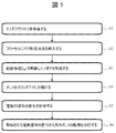
- FIG. 1 is a flow chart showing the biomolecule analysis method according to the first embodiment.
- nucleic acids are used as an example of a biopolymer and nucleotides are measured as an example of a biomolecule will be described.
- Step S1 Preparation of biomolecule analyzer
- a biomolecule analyzer including a solid-state nanopore device (biomolecular analysis device).
- a nanopore device can be fabricated by providing a thin film in which nanopores are to be formed and placing the thin film in a flow cell. As a result, liquid reservoirs are formed on both sides of the thin film.
- a first electrode is arranged in one liquid tank (first liquid tank), and a second electrode is arranged in the other liquid tank (second liquid tank).
- a power supply that applies a voltage is connected between the first and second electrodes of such a nanopore device.
- the operator installs an ammeter that measures the current between the first electrode and the second electrode.
- the biomolecule analyzer is prepared.
- the biomolecule analyzer of this embodiment is provided with a biopolymer decomposing unit that is arranged upstream of the thin film in which nanopores are formed.
- the biopolymer decomposing unit has a channel through which the biopolymer flows, and decomposes the biopolymer into monomers (biomolecules) in the channel.
- Substances capable of degrading biopolymers such as biopolymer-degrading enzymes (exonucleases and analogues thereof), high-concentration acids (pyrophosphoric acid, hydrochloric acid, etc.), are placed in the channels.
- the biopolymer decomposing unit may be configured to irradiate the channel with a laser beam capable of decomposing the biopolymer.
- Step S2 encapsulation of nanopore-forming solution
- the operator fills the first liquid tank and the second liquid tank with a nanopore-forming solution (electrolyte solution) for opening nanopores from the supply port of the flow cell.
- a nanopore-forming solution electrophilic solution
- Step S3 Opening of nanopores
- the operator drives the power supply to apply a voltage for nanopore opening between the first electrode and the second electrode, and by dielectric breakdown, nanopores with a predetermined diameter are formed in the thin film.
- Step S4 Biopolymer decomposition
- the operator drives the power supply to apply a voltage for analysis between the first electrode and the second electrode, and the measurement solution containing the biological polymer (nucleic acid) to be measured is injected from the sample inlet. to be enclosed.
- the biopolymer migrates in the channel and is decomposed into biomolecules (nucleotides) when passing through the biopolymer decomposition section, and each biomolecule (nucleotide) is introduced into the first liquid tank.
- Step S5 Measurement
- the operator measures changes in electrical signals (current values) from the first electrode and the second electrode using an ammeter.
- Step S6 analysis of biomolecules
- biomolecules are analyzed based on changes in electrical signals, for example, by a computer device.
- the electrical signal changes depending on the type of monomer (type of base), so it is possible to determine the sequence based on the pattern of the electrical signal. Details of such methods are disclosed in the literature (AH Laszlo, et al., Nature Biotechnology 32, 829, 2015).
- the present inventor unexpectedly found that when using a measurement solution containing ammonium ions as electrolyte cations and sulfate ions as anions, When the nanopore diameter is 1.4 nm or more, the nucleotide-derived signal cannot be confirmed, whereas when the nanopore diameter is smaller than 1 nm, the nucleotide-derived signal begins to be clearly confirmed, and the four types of nucleotides that constitute the biopolymer. We found that the amount of sequestration was distinctly different.
- the biomolecule by using a nanopore having a diameter of ⁇ 20% or less of the diameter of the biomolecule (specifically, for example, a diameter of 1 nm or less) and using an electrolyte solution containing ammonium ions and sulfate ions as the measurement solution, the biomolecule It was found that the ability to distinguish between
- the measurement solution (hereinafter sometimes simply referred to as "electrolyte solution”) contains ammonium ions (NH 4 + ) as electrolyte cations and sulfate ions ( SO 4 2- ). That is, the electrolyte of the electrolytic solution produces ammonium ions as cations and sulfate ions as anions.
- electrolyte solution contains ammonium ions (NH 4 + ) as electrolyte cations and sulfate ions ( SO 4 2- ). That is, the electrolyte of the electrolytic solution produces ammonium ions as cations and sulfate ions as anions.
- Both the nanopore-forming solution and the metering solution can also contain ammonium ions and sulfate ions.
- ammonium sulfate can be used as the electrolyte (salt) that generates ammonium ions and sulfate ions.
- Sulfate salts and ammonium salts that ionize in solvents can also be used as electrolytes.
- Sulfates include, for example, magnesium sulfate, sodium sulfate, potassium sulfate, copper sulfate, and iron sulfate.
- ammonium salts include ammonium chloride and ammonium carbonate.
- the electrolyte solution may contain ions other than ammonium ions and sulfate ions. Cations can be selected, for example, from any metal ion. However, monovalent metal ions such as potassium ions may promote bond dissociation of dangling bonds on the SiN surface. Divalent metal ions have a certain effect in reducing noise superimposed on the baseline current, but when present in high concentrations, they cause reactions with other ions to form precipitates. Therefore, when the electrolyte solution contains cations other than ammonium ions, it is necessary to appropriately adjust the type and concentration thereof.
- the anion can be selected depending on compatibility with the electrode material.
- the anions contained in the electrolyte solution can be halide ions (chloride ions, bromide ions, iodide ions).
- the anion may be an organic anion represented by glutamate ion and the like.
- the electrolyte solution can coexist with ammonium sulfate or electrolytes (salts) other than sulfates and ammonium salts.
- electrolytes include, for example, KCl, NaCl, LiCl, CsCl, and the like.
- ferricyanide and ferrocyanide may coexist.
- the electrolyte solution in the first liquid tank contains a substrate and a buffer suitable for driving the molecular motor. Let It is also possible to mix a buffering agent for stabilization of biomolecules.
- MgSO 4 , MgCl 2 , Tween (registered trademark), HEPES, Tris-HCl, EDTA, glycerol, etc. can be mixed as buffers.
- solvent for the electrolyte solution a solvent that can stably disperse biomolecules, does not dissolve the electrodes in the solvent, and does not interfere with electron exchange with the electrodes can be used.
- Solvents for the electrolyte solution include, for example, water, alcohols (methanol, ethanol, isopropanol, etc.), acetic acid, acetone, acetonitrile, dimethylformamide, dimethylsulfoxide and the like. Water is typically used when nucleic acids are to be measured as biomolecules.
- the lower limit of the electrolyte concentration can be set to 0.01M.
- the ammonium sulfate concentration can be 0.01 M or more and the saturation concentration or less, depending on the case, 0.01 M or more and 4 M or less, or 0.01 M or more. It can be 2M or less.
- the ratio of the ammonium sulfate concentration to the total salt concentration can be 5% or more and less than 100%.
- the ratio of ammonium sulfate concentration to total salt concentration can be 25% or more and less than 100%, or 50% or more and less than 100%.
- the ratio of the sulfate ion concentration to the total anion concentration can be 5% or more and less than 100%.
- the ratio of sulfate ion concentration to total anion concentration can be 25% or more and less than 100%, or 50% or more and less than 100%.
- the ratio of the ammonium ion concentration to the total concentration of cations can be 5% or more and less than 100%.
- the ratio of ammonium ion concentration to total cation concentration can be 25% or more and less than 100%, or 50% or more and less than 100%.
- Nanopores can be formed not only by dielectric breakdown, but also by microfabrication or processing using a TEM device in advance.
- the operator assembles the nanopore device using a thin film in which nanopores are formed in advance, and steps S2 and S3 are not performed.
- the nanopore-forming solution contains ammonium ions (NH 4 + ) as electrolyte cations and sulfate ions (SO 4 2 ⁇ ) as anions, similarly to the measurement solution described above.
- NH 4 + ammonium ions
- SO 4 2 ⁇ sulfate ions
- the biomolecule analysis method uses a nanopore device having nanopores with a diameter of ⁇ 20% or less of the diameter of the biomolecule, and the measurement solution contains ammonium ions as cations and anions contains sulfate ions as Other than that, it can be carried out using the same equipment, steps and conditions as the conventional method.
- the measurement solution contains ammonium ions as cations and anions contains sulfate ions as Other than that, it can be carried out using the same equipment, steps and conditions as the conventional method.
- the measurement solution it is possible to reduce the variability in the amount of sequestration signal derived from biomolecules (nucleotides) passing through the nanopore, and the type of passing biomolecules (nucleotides) can be detected with high signal-to-noise. It can be determined by the ratio.
- nanopores with a diameter of ⁇ 10% or less of the diameter of the biomolecule variations in the amount of blocking signal derived from the biomolecule can be further reduced.
- blockage signals derived from nucleotides can be detected. At this time, since the variance of the blocked signal amounts derived from various nucleotides is reduced, determination of each nucleotide type is facilitated.
- the biomolecular analysis reagent of the present disclosure can be provided as a measurement consumable, and contains the electrolyte of the electrolyte solution described above as a component. That is, when the biomolecular analysis reagent in the biomolecular analysis kit is made into a solution, it contains an ammonium ion as a cation and a sulfate ion as an anion. Biomolecular analysis reagents are used as measurement reagents (optionally nanopore-forming reagents and measurement reagents). Also, a biomolecule analysis device (nanopore device) is provided as a measurement consumable, and includes nanopores having the dimensions described above as constituent elements.
- a biomolecule analysis device can be provided in a state in which nanopores of 1 nm or less are formed in advance.
- the biomolecular analysis device can be provided in the state of only a thin film, and nanopores of 1 nm or less are formed after being set in the biomolecular analysis device immediately before measurement.
- the biomolecule analysis kit of the present disclosure can be provided together with a manual that describes the procedure for use, the amount of use, and the like.
- the biomolecular analysis reagents may be provided in a ready-to-use state (nanopore-forming solution and measurement solution described above), or may be provided as a concentrated solution for dilution with a suitable solvent at the time of use, or It may also be in a solid state (eg, powder, etc.) for reconstitution with a suitable solvent at the time of use.
- the form and preparation of such biomolecular analytical reagents can be understood by those skilled in the art.
- the biomolecule analysis device may be provided in contact with the biomolecule analysis reagent, or may be set in the biomolecule analysis apparatus immediately before measurement and then contacted with the reagent.
- the nanopore-forming reagent is used to form nanopores by dielectric breakdown by applying a voltage between the two liquid reservoirs formed on both sides of the thin film.
- a measurement reagent is used in passing biomolecules through the nanopore and measuring the current flowing through the nanopore (blockage current).
- the electrolyte concentration of the nanopore-forming reagent and the electrolyte concentration of the measurement reagent may be the same or different.
- the nanopore-forming reagent may be of conventional composition.
- the biomolecular analysis kit contains a biomolecular analysis reagent, which, when used as a measurement solution, produces ammonium ions as cations and sulfate ions as anions.
- Nanopores of 1 nm can be formed in the thin film of the biomolecular analysis device using the nanopore forming solution.
- FIG. 2A is a schematic cross-sectional view showing the configuration of the biomolecule analyzer 1 according to the first embodiment.
- the biomolecule analyzer 1 decomposes a biopolymer in a pretreatment mechanism (biopolymer decomposition mechanism), and measures the properties of the decomposed biomolecules by measuring the ion current using the blocking current method. be.
- the biomolecule analyzer 1 includes a nanopore device 100, an ammeter 106, a power supply 107, a computer 108 and a biopolymer decomposition mechanism 110.
- the nanopore device 100 includes a thin film 102 having nanopores 101 formed therein, a first liquid reservoir 104A and a second liquid reservoir 104B, a first electrode 105A and a second electrode 105B.
- the first liquid tank 104A and the second liquid tank 104B are arranged so as to be in contact with the thin film 102 with the thin film 102 interposed therebetween, and are filled with an electrolytic solution 103 inside.
- a first electrode 105A is provided in the first liquid tank 104A
- a second electrode 105B is provided in the second liquid tank 104B.
- the nanopore device 100 of FIG. 2A shows a state in which nanopores 101 are formed in a thin film 102, and biomolecules 109, which are products decomposed by a biopolymer decomposition mechanism 110, are sequentially introduced into the nanopores 101.
- the biomolecule 109 may be any object to be measured that changes its electrical properties, particularly its resistance value, when passing through the nanopore, and typically includes single-stranded DNA, double-stranded DNA, RNA, and PNA (peptide nucleic acid). Examples include nucleotides, protein-constituting amino acids, and modified versions thereof (eg, nucleotide analogues).
- the biomolecule 109 needs to pass through the nanopore according to its sequence.
- transportation by electrophoresis can be adopted, but a solvent flow generated by a pressure potential difference or the like may also be used.
- the electrolyte solution 103 is the aforementioned nanopore forming solution or measurement solution.
- the capacity of the electrolyte solution 103 is, for example, on the order of microliters or milliliters.
- a power supply 107 applies a predetermined voltage between the first electrode 105A and the second electrode 105B.
- a voltage is applied between the first electrode 105A and the second electrode 105B, a potential difference is generated between both surfaces of the thin film 102 on which the nanopores 101 are formed, causing the upper first liquid chamber 104A (cis chamber) to Dissolved biomolecules 109 are migrated in the direction of the second liquid tank 104B (trans tank) positioned below.
- the ammeter 106 measures the ion current (blockage signal) flowing between the first electrode 105A and the second electrode 105B, and outputs the measured value to the computer 108.
- the ammeter 106 has an amplifier that amplifies the current flowing between the electrodes by applying a voltage, and an ADC (Analog to Digital Converter) (not shown).
- a detected value which is the output of the ADC, is output to the computer 108 .
- the computer 108 controls the voltage applied by the power supply 107 to the first electrode 105A and the second electrode 105B.
- the computer 108 also analyzes the biomolecules 109 based on the detected current value from the ammeter 106 . More specifically, the computer 108 acquires the sequence information of the biomolecule 109 based on the ion current (blockage signal) value.
- the most influential nanopore measurement method in which the technology of the present disclosure is effective is the method of measuring the blocking current as described above, but it is also possible to add the following method to supplement the information.
- One is to provide a pair of electrodes in addition to the first electrode 105A and the second electrode 105B in the vicinity of the nanopore, apply a voltage between the pair of electrodes, and generate a tunnel current when biomolecules pass through.
- a FET device is provided in a nanopore membrane and the signal change of the transistor obtained by the device is measured.
- Raman scattered light is generated by irradiating light and generating a near-field.
- optical signals such as absorption, reflection, and fluorescence characteristics of light irradiated near the nanopore.
- the computer 108 typically includes an ion current measuring device, an analog-to-digital output conversion device, a data processing device, a data display output device, and an input/output auxiliary device.
- the ion current measuring device is equipped with a current-voltage conversion type high-speed amplifier circuit.
- a data processing device includes an arithmetic unit, a temporary memory device, and a non-volatile memory device. External noise can be reduced by covering the nanopore device 100 with a Faraday cage.
- the ammeter 106, the power supply 107 and the computer 108 may be configured integrally with the nanopore device 100 instead of being separate members from the nanopore device 100.
- the thin film 102 in which the nanopore 101 is formed is a thin film (solid pore) made of a material that can be formed by semiconductor microfabrication technology.
- materials that can be formed by semiconductor microfabrication technology include silicon nitride (SiN), silicon oxide (SiO 2 ), silicon oxynitride (SiON), hafnium oxide (HfO 2 ), molybdenum disulfide (MoS 2 ), and graphene.
- the thickness of thin film 102 can be from 1 ⁇ (Angstroms) to 200 nm, optionally from 1 ⁇ to 100 nm, or from 1 ⁇ to 50 nm, and specifically, for example, about 5 nm.
- the area of the thin film 102 is an area in which two or more nanopores 101 are difficult to form when the nanopores 101 are formed by voltage application, and can be an area that is allowable in terms of strength. As an example, the area can be about 100-500 nm 2 , for example. Further, by setting the film thickness of the thin film 102 to a film thickness that enables the formation of nanopores 101 having an effective film thickness equivalent to one base, it is possible to achieve single-base resolution of DNA. As an example, the film thickness can be on the order of 7 nm or less. Note that the thin film 102 may have a structure in which both sides are sandwiched by other thin films having through holes. Just do it.
- An appropriate dimension (diameter) of the nanopore 101 can be selected according to the type of the biomolecule 109 to be analyzed.
- the diameter of the nanopore 101 is designed to be ⁇ 20% of the diameter of the biomolecule 109 which is the measurement object.
- the dimensions of the nanopore 101 can be, for example, 0.7 nm to 1.0 nm.
- the depth of the nanopore 101 can be adjusted by adjusting the thickness of the thin film 102.
- the depth of the nanopore 101 can be two or more times the depth of the biomolecule 109 (monomer unit), optionally three or more times, or five or more times as large.
- the depth of the nanopore 101 can be three or more bases, eg, about 1 nm or more.
- the shape of the nanopore 101 is basically circular, but can also be elliptical or polygonal.
- the thin films 102 having nanopores 101 can be arranged regularly.
- the intervals at which the thin films 102 are arranged can be 0.1 ⁇ m to 1 mm, or 1 ⁇ m to 700 ⁇ m, depending on the electrodes used and the capabilities of the electrical measurement system.
- the method for forming the nanopores 101 in the thin film 102 is not particularly limited.
- electron beam irradiation by a transmission electron microscope (TEM) or dielectric breakdown by voltage (pulse voltage, etc.) application can be used.
- the method of forming the nanopore 101 is described, for example, in “Itaru Yanagi et al., Sci. Rep. 4, 5000 (2014)” or "A. J. Storm et al., Nat. Mat. 2 (2003)”. method can be used.
- the first liquid tank 104A and the second liquid tank 104B which can contain the measurement solution that contacts the thin film 102, can be appropriately provided with materials, shapes, and sizes that do not affect the measurement of blockage current.
- a measurement solution is injected so as to come into contact with the thin film 102 that partitions the first liquid tank 104A and the second liquid tank 104B.
- the first electrode 105A and the second electrode 105B can be made of a material capable of undergoing an electron transfer reaction (Faraday reaction) with the electrolyte in the measurement solution, typically silver halide or halogen made of alkaline silver. From the standpoint of potential stability and reliability, silver or silver-silver chloride can be used.
- Faraday reaction electron transfer reaction
- the first electrode 105A and the second electrode 105B may be made of a material that serves as polarized electrodes, such as gold or platinum.
- a substance capable of assisting the electron transfer reaction such as potassium ferricyanide or potassium ferrocyanide, can be added to the measurement solution in order to ensure a stable ion current.
- a substance capable of undergoing an electron transfer reaction such as ferrocene, can be immobilized on the polarized electrode surface.
- the structure of the first electrode 105A and the second electrode 105B may be entirely composed of the above material, or the above material may be coated on the surface of the base material (copper, aluminum, etc.).
- the shape of the first electrode 105A and the second electrode 105B is not particularly limited, but a shape that increases the surface area in contact with the measurement solution can be adopted.
- the first electrode 105A and the second electrode 105B are joined with wiring to send an electrical signal to the measuring circuit (ammeter 106).
- the biomolecule analyzer 1 includes the above configuration as elements.
- the nanopore-type biomolecule analyzer 1 described above can be provided together with an instruction manual that describes the procedure for use, the amount of use, and the like. Such forms and preparations can be understood by those skilled in the art.
- the nanopore device 100 may be provided in a ready-to-use state in which nanopores are formed, or may be provided in a state in which the nanopores are formed at the recipient.
- the biomolecule analyzer includes a biopolymer decomposition mechanism, and biomolecules (nucleotides), which are decomposition products of biopolymers (nucleic acids), are transported to the liquid tank above the thin film.
- the electrolyte solution enclosed on both sides of the thin film contains ammonium ions as cations and sulfate ions as anions.
- the diameter of the nanopore through which the biomolecule (nucleotide) to be measured passes is adjusted to ⁇ 20% of the diameter of the biomolecule (nucleotide). This makes it possible to reduce variations in the amount of sequestration signal derived from biomolecules passing through the nanopore, and to determine the type of passing biomolecules with a high signal-to-noise ratio.
- pretreatment of the biopolymer Prior to introducing the biopolymer into the biopolymer degradation mechanism 110, pretreatment of the biopolymer can be performed.
- the pretreatment process will be described using the case where the biopolymer is DNA as an example.
- a pretreatment for example, linearization and single stranding of DNA are performed.
- FIG. 2B is a schematic diagram showing the flow from the pretreatment and decomposition of the DNA polymer until it becomes measurable with the nanopore.
- the flow of DNA linearization in the pretreatment chip 10 is shown in the upper left part of FIG. 2B.
- the pretreatment chip 10 has a sample recovery section 11, a microchannel 12 and a nanochannel 13, which form one continuous channel.
- DNA extracted from cells, for example, is collected in the sample collection unit 11 .
- the extracted DNA has a three-dimensional structure and is in a coiled state (Gaussian coil).
- the DNA changes into a state of being elongated by passing through the nanochannel 13 (for example, submicron order).
- the pretreatment chip 10 has a plurality of channels (three in FIG. 2B) arranged in parallel.
- DNA single-strand formation is shown in the upper center of Figure 2B.
- Single-stranding of DNA can be carried out, for example, by a reaction using a single-strand-degrading enzyme 15 arranged in the nanochannel 13, as shown in the middle middle part of FIG. 2B.
- the single-stranded DNA passes through the several-nanometer channel 14 and is introduced into the biological polymer decomposition mechanism 110 .
- DNA can be made single-stranded by passing through a nanochannel 14 having a diameter equal to or smaller than that of a double strand and equal to or larger than that of a single strand without using an enzyme. can.
- the single-stranded DNA that has passed through the nanochannel 14 passes through the biopolymer degradation mechanism 110 to become nucleated from the end, and in the order of cleavage, by diffusion and electrophoresis. It passes through the nanopore 101.
- the biopolymer degradation mechanism 110 is again populated with enzymes capable of single-strand binding and nucleotide degradation. Alternatively, a high concentration of hydrochloric acid is retained.
- the biological polymer decomposition mechanism 110 is configured to be able to irradiate DNA with laser light.
- one thin film 102 has only one nanopore 101 .
- FIG. 3 is a schematic cross-sectional view showing the configuration of the biomolecule analyzer 2.
- FIG. 3 the same components as those of the biomolecule analyzer 1 shown in FIG. 2A are denoted by the same reference numerals, and redundant explanations are omitted.
- the biomolecule analyzer 2 differs from the biomolecule analyzer 1 in FIG. 2A in that it includes a nanopore device 200, which is an array device.
- thin film 102A has a plurality of nanopores 101
- second liquid reservoir 104B under thin film 102A is divided into a plurality of spaces by partition walls (specifically, side walls of thin film 102C).
- partition walls specifically, side walls of thin film 102C.
- Thin films 102B and 102C that fix thin film 102A are provided with through holes at positions corresponding to nanopores 101, and the side walls of the through holes of thin film 102C form a plurality of spaces (individual tanks).
- a second electrode 105B is provided in each of the plurality of spaces.
- the first liquid tank 104A is also divided into individual spaces by partition walls 111 and insulated so that the biopolymers are not mixed. Therefore, the current flowing through each nanopore 101 can be measured independently.
- An individual biopolymer decomposition mechanism 110 is provided in each first liquid tank 104A.
- the nanopore-forming solution or measurement solution may be the one described above.
- the types of nucleotides that pass through the nanopore can be determined with high accuracy. Since the biomolecule analyzer 2 can perform measurements in parallel, it is possible to perform monomer sequence analysis of biomolecules at a very high throughput while maintaining high analysis accuracy.
- biomolecular analysis method, biomolecular analysis reagent, and biomolecular analysis device can be used, for example, for analysis of biomolecules composed of nucleic acids, and for testing, diagnosis, treatment, drug discovery, basic research, etc. using the analysis. useful in the field.
- a thin film was produced by a semiconductor microfabrication technique in the following procedure. First, Si 3 N 4 /polySi/Si 3 N 4 were deposited in the order of 5 nm/150 nm/100 nm on the surface of an 8-inch Si wafer with a thickness of 725 mm. A film of Si 3 N 4 was formed to a thickness of 105 nm on the back surface of the Si wafer.
- the polySi of the intermediate layer may be SiO.
- Si 3 N 4 on the uppermost Si wafer surface was removed by reactive ion etching in a 500 nm square area.
- Si 3 N 4 on the back surface of the Si wafer was removed by reactive ion etching in a 1038 ⁇ m square area.
- the Si substrate exposed by etching was further etched with TMAH (Tetramethylammonium hydroxide).
- TMAH Tetramethylammonium hydroxide
- the wafer surface was covered with a protective film (ProTEK (registered trademark) B3primer and ProTEK (registered trademark) B3, manufactured by Brewer Science) to prevent etching of polySi on the surface side.
- the exposed polySi layer of 500 nm square was removed with an NH 4 OH solution.
- a partition with an exposed Si 3 N 4 thin film having a thickness of 5 nm was obtained.
- Hydrophilization can also be carried out under conditions of 10 W, 20 sc
- the voltage is applied not only during the formation of the nanopore, but also during the measurement of the ion current flowing through the nanopore after the nanopore is formed.
- the lower liquid tank is called a cis tank
- the upper liquid tank is called a trans tank.
- the voltage Vcis applied to the electrode on the cis tank side is set to 0 V
- the voltage Vtrans is applied to the electrode on the trans tank side.
- the voltage Vtrans is generated by a pulse generator (eg 41501B SMU AND Pulse Generator Expander, manufactured by Agilent Technologies).
- the current value after pulse application can be read with an ammeter (eg 4156B PRECISION SEMICONDUCTOR ANALYZER, manufactured by Agilent Technologies).
- an ammeter eg 4156B PRECISION SEMICONDUCTOR ANALYZER, manufactured by Agilent Technologies.
- the diameter of the nanopore can be estimated from the ion current value.
- Table 1 shows criteria for condition selection.
- n-th pulse voltage application time t n (where n>2 is an integer) is determined by the following equation.
- Example 1 Change in Nanopore Diameter
- nanopores were formed using 0.5 M (NH 4 ) 2 SO 4 +0.5 M KCl + 10 mM Tris-HCl solution (pH 7.5) as the nanopore forming solution.
- the pore conductivity obtained with this nanopore-forming solution was 1.94 nS, and the nanopore diameter converted to an effective film thickness of 3.5 nm was 0.94 nm.
- the effective film thickness was obtained based on the base current value dependence of the blockage amount when measuring dsDNA, assuming that the effective diameter of dsDNA was 2.5 nm.
- the nanopore-forming solution is discharged, and the cis tank is replaced with a solution of 0.2 M (NH 4 ) 2 SO 4 + 1x enzyme buffer (pH 7.5) + Tween (registered trademark) 20 (no Mg) as a measurement solution,
- the trans bath was replaced with a 0.5M (NH 4 ) 2 SO 4 +0.5M MgSO 4 +10 mM Tris-HCl (pH 7.5) solution.
- the change in baseline current over time was measured.
- 100 ⁇ M dNTP was added and the time change of ion current (blockage signal amount) was measured.
- the results are shown in FIG. 4A.
- Comparative example 1 the blocked signal amount of the dNTP-derived signal was compared when nanopores of sizes different from those in Example 1 were formed. Specifically, a nanopore having a conductivity of 5.74 nS was formed with the nanopore-forming solution, and the diameter of the nanopore calculated assuming an effective film thickness of 3.5 nm was 1.72 nm. In the same manner as in Example 1, except that the diameter of the nanopore was changed, the change over time of the baseline current and the change over time of the ion current after addition of 100 ⁇ M dNTP were measured. The results are shown in Figure 4B.
- (result) 4A is a graph showing baseline current after addition of 100 ⁇ M dNTPs in Example 1.
- FIG. 4A As shown in FIG. 4A, in Example 1, the distribution of the blockade signal amount derived from dNTPs was Ib to 90 pA (LPF 2 kHz), and a clear signal thought to be derived from dNTPs was obtained.
- FIG. 4B is a graph showing the ion current after addition of 100 ⁇ M dNTP in Comparative Example 1.
- FIG. 4B in Comparative Example 1, the distribution of the amount of blockage signal derived from dNTPs was from Ib to 60 pA (LPF 2 kHz), and only signals considered to be derived from noise in the base current were acquired. From this, by using an ammonium sulfate solution as a measurement solution as in Example 1 and having a nanopore diameter of 1 nm or less (0.94 nm), compared to the case of greater than 1 nm as in Comparative Example 1, It was found that the dNTP-derived blocked signal level was stable and a clear signal could be detected without being buried in noise.
- Example 2 Change of measurement solution
- Example 2 nanopores with a diameter of about 0.9 nm were formed using 0.5 M (NH 4 ) 2 SO 4 +0.5 M KCl + 10 mM Tris-HCl solution (pH 7.5) as the nanopore forming solution.
- the time change of the current value after adding 100 ⁇ M dCTP was measured without replacing with another solution.
- the time change of the baseline current was measured. The results are shown in Figure 5B.
- Comparative example 2 In Comparative Example 2, after forming nanopores with a diameter of about 0.9 nm in the same manner as in Example 2, the nanopore-forming solution was discharged and replaced with a 1M KCl solution as a measurement solution. After replacement with the measurement solution, the time change of the current value after addition of 100 ⁇ M dCTP was measured. The results are shown in FIG. 5A.
- (result) 5A shows the time change of the current value after addition of 100 ⁇ M dCTP in 1 M KCl in Comparative Example 2.
- FIG. 5A it can be seen that the current values range from about 0.05 to 0.55 nA.
- FIG. 5B shows changes in current values over time after addition of 100 ⁇ M dCTP in 0.5 M (NH 4 ) 2 SO 4 +0.5 KCl+10 mM Tris-HCl solution (pH 7.5) in Example 2. As shown in FIG. 5B, it can be seen that the current values range from about 0.04 to 0.3 nA. From FIGS. 5A and 5B, it can be seen that Example 2 has a narrower range of current values and less variation than Comparative Example 2.
- FIG. 5B shows changes in current values over time after addition of 100 ⁇ M dCTP in 0.5 M (NH 4 ) 2 SO 4 +0.5 KCl+10 mM Tris-HCl solution (pH 7.5) in Example 2. As shown in FIG. 5B, it can be seen that the current values range from about 0.04 to 0.3 nA. From FIGS. 5A and 5B, it can be seen that Example 2 has a narrower range of current values and less variation than Comparative Example 2.
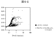
- FIG. 5C is a scatter diagram of the amount of dCTP-derived blocking signal and the blocking time obtained in Example 2 and Comparative Example 2. As shown in FIG. 5C, it was confirmed that the amount of sequestration in Example 2 was clearly smaller than the amount of sequestration in Comparative Example 2.
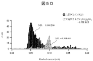
- 5D is a histogram of sequestration amounts in Example 2 and Comparative Example 2.
- FIG. 5D in the 0.5 M (NH 4 ) 2 SO 4 + 0.5 KCl + 10 mM Tris-HCl solution (pH 7.5) used in Example 2, the sequestration amount of 1 MdCTP in Comparative Example 2 had a small variance. I know it will be. In addition, it can be seen that the variance of the amount of blockage is about 6 times smaller than the difference.
- Example 3 In a nanopore device fabricated under the same conditions as in Example 1, after nanopore formation, 0.5 M (NH 4 ) 2 SO 4 + 0.5 M KCl solution was used as a measurement solution, and 100 ⁇ M dCTP, dATP, dTTP, or dGTP was added. The amount of blockage signal was compared by sequentially replacing the solutions. The results are shown in Figure 6B.
- Comparative Example 3 Using measurement solutions each containing dGTP, dATP, dTTP, and dCTP under the conditions described in Non-Patent Document 2, the blockage signal levels were compared. Specifically, the conditions of Comparative Example 3 are the same as those of Example 3, except that nanopores were formed using a TEM apparatus and 1M KCl was used as the measurement solution. The results are shown in FIG. 6A.
- (result) 6A is a scatter diagram and a histogram of the amount of blocking signal derived from each nucleotide in Comparative Example 3.
- FIG. 6A As shown in FIG. 6A, the histograms of the amount of sequestration derived from each nucleotide overlap each other, indicating no clear separation.
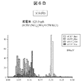
- FIG. 6B shows a histogram of sequestration amounts when counting nucleotides in 0.5 M (NH 4 ) 2 SO 4 +0.5 M KCl in Example 3.
- the peak position of the histogram distribution of each nucleotide is clearly different, and the overlap of the distributions is small.
- 0.5M (NH 4 ) 2 SO 4 + 0.5M KCl was used as the measurement solution, but measurement at a salt concentration higher than this concentration is also possible, and clearer separation can be expected. can.
- the present disclosure is not limited to the embodiments described above, and includes various modifications.
- the above-described embodiments have been described in detail in order to explain the present disclosure in an easy-to-understand manner, and do not necessarily include all the configurations described.
- part of an embodiment can be replaced with the configuration of another embodiment.
- the configuration of another embodiment can be added to the configuration of one embodiment.
- a part of the configuration of each embodiment can be added, deleted or replaced with a part of the configuration of another embodiment.
Landscapes
- Chemical & Material Sciences (AREA)
- Life Sciences & Earth Sciences (AREA)
- Health & Medical Sciences (AREA)
- Engineering & Computer Science (AREA)
- Physics & Mathematics (AREA)
- General Health & Medical Sciences (AREA)
- Biomedical Technology (AREA)
- Biochemistry (AREA)
- Immunology (AREA)
- Analytical Chemistry (AREA)
- Organic Chemistry (AREA)
- General Physics & Mathematics (AREA)
- Pathology (AREA)
- Wood Science & Technology (AREA)
- Zoology (AREA)
- Bioinformatics & Cheminformatics (AREA)
- Proteomics, Peptides & Aminoacids (AREA)
- Biophysics (AREA)
- Molecular Biology (AREA)
- Electrochemistry (AREA)
- Biotechnology (AREA)
- Medicinal Chemistry (AREA)
- Chemical Kinetics & Catalysis (AREA)
- Nanotechnology (AREA)
- Microbiology (AREA)
- Spectroscopy & Molecular Physics (AREA)
- Food Science & Technology (AREA)
- Urology & Nephrology (AREA)
- Hematology (AREA)
- General Engineering & Computer Science (AREA)
- Genetics & Genomics (AREA)
- Sustainable Development (AREA)
- Investigating Or Analyzing Materials By The Use Of Electric Means (AREA)
Abstract
本開示の生体分子分析方法は、生体分子の直径の±20%の範囲の直径を有するナノポアを有する薄膜と、前記薄膜により隔てられる第1の液槽及び第2の液槽と、前記第1の液槽に配置される第1の電極と、前記第2の液槽に配置される第2の電極と、生体ポリマを前記生体分子に分解する生体ポリマ分解機構と、を備える生体分子分析デバイスを準備することと、前記生体ポリマ分解機構において生体ポリマを前記生体分子に分解することと、前記第1の液槽及び前記第2の液槽に計測溶液が封入された状態で、前記第1の電極及び前記第2の電極間に電圧を印加して、前記第1の電極及び前記第2の電極間に流れる電流を計測することと、を含み、前記計測溶液は、アンモニウムイオン及び硫酸イオンを含むことを特徴とする。
Description
本開示は、生体分子分析方法、生体分子分析試薬及び生体分子分析デバイスに関する。
次世代DNAシーケンサの分野では、伸長反応や蛍光ラベルを行うことなく、DNAの塩基配列を電気的に直接計測する方法が注目されている。具体的には、ナノポアDNAシーケング方式の研究開発が活発に進められている。この方式は、試薬を用いることなくDNA鎖を直接計測し、塩基配列を決定する方式である。
ナノポアDNAシーケンシング方式では、薄膜に形成された細孔(以下「ナノポア」という。)をDNA鎖が通過することで生じる封鎖電流を計測することにより、塩基配列を計測する。DNA鎖に含まれる個々の塩基種の違いにより封鎖電流が変化するので、封鎖電流量を計測することで塩基種を順次同定することができる。この方式では、蛍光標識した基質を酵素の伸長活性により取り込み解析する方式とは異なり、直接DNA鎖の情報を取得することになるため、その読み取り塩基長さは酵素の伸長活性に限定されず原理的に長鎖のDNA解読が可能であり、DNA鎖への修飾も直接解読することができる。
ナノポアDNAシーケンシング方式においてDNAを分析する際に使用する生体分子分析デバイスは、一般的に、電解質溶液が満たされている第1及び第2の液槽と、その第1及び第2の液槽を仕切る薄膜と、第1の液槽に設けられる第1の電極及び第2の液槽に設けられる第2の電極とを備える。生体分子分析デバイスは、アレイデバイスとして構成することもできる。アレイデバイスは、薄膜によって仕切られる液室の組を複数個備えるデバイスをいう。例えば第1の液槽を共通槽とし、第2の液槽を複数個の個別槽とする。この場合、共通槽と個別槽の各々に電極を配置する。
この構成において、第1の液槽と第2の液槽の間に電圧が印加されると、ナノポアにはナノポア径に応じたイオン電流(ベースライン電流)が流れる。また、ナノポアには、印加した電圧に応じた電位勾配が形成される。DNAなどの生体分子を第1の液槽に導入すると、拡散及び電位勾配に応じて、生体分子がナノポアを介して第2の液槽へ搬送される。このとき、ナノポアを封鎖する、各核酸の封鎖率に応じて生体分子内の分析が実施される。なお、生体分子分析装置は、生体分子分析デバイスに設けられた第1及び第2の電極の間に流れるイオン電流(封鎖信号)を測定する測定部を有し、測定部は、測定されたイオン電流(封鎖信号)の値に基づいて生体分子の配列情報を取得する。
ナノポアをDNAが閉塞することによって発生する封鎖信号は、ナノポア内部の封鎖、並びにナノポア入口及び出口に滞留する物質に依存して発生する。したがって、DNA鎖の分解能は、このナノポア内部の抵抗、並びにナノポアの入口及び出口の抵抗成分によって決定される。ここで、ナノポアDNAシーケンシングにおいてはDNAを鎖のまま解析することが前提とされている。しかしながら、DNAのナノポア通過速度を制御するためにナノポア入口に酵素を配置する場合があり、この酵素も封鎖抵抗成分の一つとなりうる。また、DNAがナノポアの入口及び出口でコイル状をとることによってもナノポアの入口及び出口の抵抗成分が変化する。これらの抵抗成分に起因する封鎖信号量の変化は、塩基の種類に応じた電流信号の変化量を検出する際の妨げになる。
抵抗成分に起因する封鎖信号量の変化を避けるために、鎖状のDNAを解析するのではなく、ヌクレオチドに分解して各ヌクレオチドの封鎖量に基づいて一塩基ずつ塩基種を決定する手法が考えられる。
非特許文献1には、バイオナノポアを用いてKCl溶液にてヌクレオチドの分離度を計測することが記載されている。一方、非特許文献2には、ヌクレオチドをナノポアに通過させて信号の分離度を確かめることが記載されている。
Clark, J. et al., Nature Nanotechnology, DOI: 10.1038/NNANO.2009.12
Yang, H. et al., J. Phys. Chem. B 2018, 122, 7929-7935
ところで、固体ナノポアはLSIとの親和性が高いことから、高集積化が期待されている。また、固体ナノポアはデバイス保管期間を長期化できることから、低コスト化実現への期待が高い。非特許文献1においては、バイオナノポアを用いた計測について記載されており、固体ナノポアについては検討がなされていない。
非特許文献2においては、固体ナノポアでヌクレオチドを計測した結果の封鎖信号の分離度が低いため、一塩基がナノポアを通過した際の封鎖信号をヌクレオチド種に変換することが困難であることが予想される。
そこで、本開示は、固体ナノポアにおける生体分子の識別能を向上する技術を提供する。
本開示の生体分子分析方法は、生体分子の直径の±20%の範囲の直径を有するナノポアを有する薄膜と、前記薄膜により隔てられる第1の液槽及び第2の液槽と、前記第1の液槽に配置される第1の電極と、前記第2の液槽に配置される第2の電極と、生体ポリマを前記生体分子に分解する生体ポリマ分解機構と、を備える生体分子分析デバイスを準備することと、前記生体ポリマ分解機構において生体ポリマを前記生体分子に分解することと、前記第1の液槽及び前記第2の液槽に計測溶液が封入された状態で、前記第1の電極及び前記第2の電極間に電圧を印加して、前記第1の電極及び前記第2の電極間に流れる電流を計測することと、を含み、前記計測溶液は、アンモニウムイオン及び硫酸イオンを含むことを特徴とする。
本開示に関連する更なる特徴は、本明細書の記述、添付図面から明らかになるものである。また、本開示の態様は、要素及び多様な要素の組み合わせ及び以降の詳細な記述と添付される請求の範囲の様態により達成され実現される。本明細書の記述は典型的な例示に過ぎず、本開示の請求の範囲又は適用例を如何なる意味に於いても限定するものではない。
本開示の技術によれば、固体ナノポアにおける生体分子の識別能を向上することができる。上記以外の課題、構成及び効果は、以下の実施形態の説明により明らかにされる。
以下、図面に基づいて、本開示の実施形態を説明する。なお、添付の図面は、本開示の原理に則った具体的な実施形態を示しているが、それらは本開示の技術の理解のためのものであり、決して本開示の技術を限定的に解釈するためのものではない。
本開示において「生体分子」とは、例えば、核酸(DNA、RNA、PNAなど)を構成するヌクレオチド及びそのアナログ、並びに、タンパク質を構成するアミノ酸及びその改変体を指し、天然物か人工物かを問わない。
また、本開示において、生体分子の「分析」とは、生体分子の特性解析を指す。生体分子の特性解析には、例えば、核酸のモノマの配列順序の分析(配列決定)、核酸の長さの決定、一塩基多型の検出、生体分子中の構造多型(コピー数多型、挿入、欠失など)の検出などがある。
[生体分子分析方法]
図1は、第1の実施形態に係る生体分子分析方法を示すフローチャートである。以下、生体ポリマの一例として核酸を用い、生体分子の一例としてヌクレオチドを計測する場合について説明する場合がある。
図1は、第1の実施形態に係る生体分子分析方法を示すフローチャートである。以下、生体ポリマの一例として核酸を用い、生体分子の一例としてヌクレオチドを計測する場合について説明する場合がある。
(ステップS1:生体分子分析装置の準備)
ステップS1において、作業者は、ソリッドステート式のナノポアデバイス(生体分子分析デバイス)を備える生体分子分析装置を準備する。具体的には、例えば、ナノポアデバイスは、ナノポアが形成されるべき薄膜を備え、フローセルに薄膜を設置することにより作製することができる。これにより、薄膜の両側にそれぞれ液槽が形成される。一方の液槽(第1の液槽)に第1の電極を配置し、他方の液槽(第2の液槽)に第2の電極を配置する。このようなナノポアデバイスの第1の電極及び第2の電極の間に電圧を印加する電源を接続する。また、作業者は、第1の電極及び第2の電極間の電流を計測する電流計を設置する。これにより、生体分子分析装置が準備される。
ステップS1において、作業者は、ソリッドステート式のナノポアデバイス(生体分子分析デバイス)を備える生体分子分析装置を準備する。具体的には、例えば、ナノポアデバイスは、ナノポアが形成されるべき薄膜を備え、フローセルに薄膜を設置することにより作製することができる。これにより、薄膜の両側にそれぞれ液槽が形成される。一方の液槽(第1の液槽)に第1の電極を配置し、他方の液槽(第2の液槽)に第2の電極を配置する。このようなナノポアデバイスの第1の電極及び第2の電極の間に電圧を印加する電源を接続する。また、作業者は、第1の電極及び第2の電極間の電流を計測する電流計を設置する。これにより、生体分子分析装置が準備される。
本実施形態の生体分子分析装置には、ナノポアが形成される薄膜より上流側に配置される生体ポリマ分解部が設けられる。生体ポリマ分解部は、生体ポリマが流れる流路を有し、流路中で生体ポリマをモノマ(生体分子)に分解する。流路には、例えば生体ポリマの分解酵素(エキソヌクレアーゼ及びその類似物など)、高濃度の酸(ピロリン酸若しくは塩酸など)など、生体ポリマを分解可能な物質が配置されている。代替的に、生体ポリマ分解部は、流路に生体ポリマを分解可能なレーザ光が照射されるように構成されていてもよい。
(ステップS2:ナノポア形成溶液の封入)
ステップS2において、作業者は、フローセルの供給口から、第1の液槽及び第2の液槽にナノポア開孔用のナノポア形成溶液(電解質溶液)を封入する。
ステップS2において、作業者は、フローセルの供給口から、第1の液槽及び第2の液槽にナノポア開孔用のナノポア形成溶液(電解質溶液)を封入する。
(ステップS3:ナノポアの開孔)
ステップS3において、作業者は、電源を駆動して第1の電極及び第2の電極間にナノポア開孔用の電圧を印加し、絶縁破壊により、所定の直径のナノポアを薄膜に形成する。
ステップS3において、作業者は、電源を駆動して第1の電極及び第2の電極間にナノポア開孔用の電圧を印加し、絶縁破壊により、所定の直径のナノポアを薄膜に形成する。
(ステップS4:生体ポリマの分解)
ステップS4において、作業者は、電源を駆動して第1の電極及び第2の電極間に分析用の電圧を印加し、サンプル注入口から計測対象である生体ポリマ(核酸)が含まれる計測溶液を封入する。その後、生体ポリマは流路内を泳動し、生体ポリマ分解部を通過する際に生体分子(ヌクレオチド)に分解され、各生体分子(ヌクレオチド)は、第1の液槽に導入される。
ステップS4において、作業者は、電源を駆動して第1の電極及び第2の電極間に分析用の電圧を印加し、サンプル注入口から計測対象である生体ポリマ(核酸)が含まれる計測溶液を封入する。その後、生体ポリマは流路内を泳動し、生体ポリマ分解部を通過する際に生体分子(ヌクレオチド)に分解され、各生体分子(ヌクレオチド)は、第1の液槽に導入される。
(ステップS5:計測)
ステップS5において、作業者は、電流計により、第1の電極及び第2の電極からの電気的信号(電流値)の変化を計測する。
ステップS5において、作業者は、電流計により、第1の電極及び第2の電極からの電気的信号(電流値)の変化を計測する。
(ステップS6:生体分子の分析)
ステップS6において、例えばコンピュータ装置により、電気的信号の変化に基づいて、生体分子を分析する。生体分子がナノポアを通過する際にモノマ種別(塩基種別)によって電気的信号が変化するため、その電気的信号のパターンによって配列決定を行うことが可能である。このような方法の詳細は文献(A.H. Laszlo, et al., Nature Biotechnology 32, 829, 2015)に開示されている。
ステップS6において、例えばコンピュータ装置により、電気的信号の変化に基づいて、生体分子を分析する。生体分子がナノポアを通過する際にモノマ種別(塩基種別)によって電気的信号が変化するため、その電気的信号のパターンによって配列決定を行うことが可能である。このような方法の詳細は文献(A.H. Laszlo, et al., Nature Biotechnology 32, 829, 2015)に開示されている。
(ナノポア径及び電解質溶液について)
本発明者は、ヌクレオチドの分析に用いられる電解質溶液について鋭意検討を行った結果、予想外にも、電解質のカチオンとしてアンモニウムイオンを含み、かつアニオンとして硫酸イオンを含む計測溶液を用いた場合に、ナノポア径が1.4nm以上ではヌクレオチド由来の信号が確認できないのに対し、ナノポア径を1nmよりも小さくすると、ヌクレオチド由来の信号が明瞭に確認され始め、かつ生体ポリマを構成する4種ヌクレオチド由来の封鎖量が明瞭に異なることを見出した。すなわち、生体分子の直径の±20%以下の直径を有する(具体的には、例えば直径1nm以下の)ナノポアを用い、計測溶液としてアンモニウムイオン及び硫酸イオンを含む電解質溶液を用いることにより、生体分子の識別能を向上できることが見出された。
本発明者は、ヌクレオチドの分析に用いられる電解質溶液について鋭意検討を行った結果、予想外にも、電解質のカチオンとしてアンモニウムイオンを含み、かつアニオンとして硫酸イオンを含む計測溶液を用いた場合に、ナノポア径が1.4nm以上ではヌクレオチド由来の信号が確認できないのに対し、ナノポア径を1nmよりも小さくすると、ヌクレオチド由来の信号が明瞭に確認され始め、かつ生体ポリマを構成する4種ヌクレオチド由来の封鎖量が明瞭に異なることを見出した。すなわち、生体分子の直径の±20%以下の直径を有する(具体的には、例えば直径1nm以下の)ナノポアを用い、計測溶液としてアンモニウムイオン及び硫酸イオンを含む電解質溶液を用いることにより、生体分子の識別能を向上できることが見出された。
したがって、本実施形態の生体分子分析方法において、計測溶液(以下、単に「電解質溶液」という場合がある)は、電解質のカチオンとしてアンモニウムイオン(NH4
+)を含み、かつ、アニオンとして硫酸イオン(SO4
2-)を含む。すなわち、電解質溶液の電解質は、カチオンとしてアンモニウムイオンを生成し、アニオンとして硫酸イオンを生成するものである。ナノポア形成溶液及び計測溶液の両方が、アンモニウムイオン及び硫酸イオンを含むこともできる。
アンモニウムイオン及び硫酸イオンを生成する電解質(塩)としては、例えば硫酸アンモニウムを用いることができる。また、電解質として、溶媒中で電離する硫酸塩及びアンモニウム塩を用いることもできる。硫酸塩としては、例えば硫酸マグネシウム、硫酸ナトリウム、硫酸カリウム、硫酸銅、硫酸鉄などが挙げられる。アンモニウム塩としては、例えば塩化アンモニウム、炭酸アンモニウムなどが挙げられる。
電気伝導度を確保するために、電解質溶液は、アンモニウムイオン及び硫酸イオン以外のイオンを含んでいてもよい。カチオンは、例えば任意の金属イオンから選択することができる。ただし、例えばカリウムイオン等の一価の金属イオン類は、SiN表面の未結合手の結合乖離を促進する虞がある。また、二価の金属イオンは、ベースライン電流に重畳されるノイズの低減に一定の効果はあるが、高濃度に存在すると他イオンと反応して沈殿を生成させる原因となる。したがって、電解質溶液にアンモニウムイオン以外のカチオンを含める場合は、その種類及び濃度を適切に調整する必要がある。アニオンは、電極材質との相性によって選定することができる。例えば電極材質としてハロゲン化銀を用いた場合、電解質溶液に含まれるアニオンは、ハロゲン化物イオン(塩化物イオン、臭化物イオン、ヨウ化物イオン)とすることができる。あるいは、アニオンは、グルタミン酸イオン等に代表される有機アニオン類であってもよい。
すなわち、電解質溶液には、硫酸アンモニウム、若しくは、硫酸塩及びアンモニウム塩以外の電解質(塩)を共存させることができる。このような電解質には、例えばKCl、NaCl、LiCl、CsClなどが挙げられる。電極にプラチナやAuを用いる際にはフェリシアン、フェロシアンを共存させてもよい。また、生体分子の任意の搬送制御を行う場合の一つの手段として分子モータを用いる場合には、第1の液槽の電解質溶液には、基質と、分子モータの駆動に適したバッファとを共存させる。生体分子の安定化のため、緩衝剤を混在させることも可能である。一般には緩衝剤としてMgSO4、MgCl2、Tween(登録商標)、HEPES、Tris-HCl、EDTA、グリセロールなどを混在させることができる。
電解質溶液の溶媒としては、生体分子を安定に分散可能であり、かつ電極が溶媒に溶解せず、電極との電子授受を阻害しない溶媒を用いることができる。電解質溶液の溶媒として、例えば、水、アルコール類(メタノール、エタノール、イソプロパノールなど)、酢酸、アセトン、アセトニトリル、ジメチルホルムアミド、ジメチルスルホキシドなどが挙げられる。生体分子として核酸を測定対象とする場合、典型的には水が用いられる。
電解質濃度の下限を設けることで、信号対ノイズ比(SNR)を向上することができる。具体的には、例えば電解質濃度の下限を0.01Mとすることができる。一方、電解質濃度の上限を妨げる要件はなく、飽和濃度まで許容することができる。すなわち、電解質溶液が電解質(塩)として硫酸アンモニウムのみを含む場合、硫酸アンモニウム濃度は、0.01M以上飽和濃度以下とすることができ、場合に応じて、0.01M以上4M以下、又は0.01M以上2M以下とすることができる。
電解質溶液が電解質(塩)として硫酸アンモニウム及び他の塩を含む場合、塩濃度の合計に対する硫酸アンモニウム濃度の割合は、5%以上100%未満とすることができる。場合に応じて、塩濃度の合計に対する硫酸アンモニウム濃度の割合は、25%以上100%未満、又は50%以上100%未満とすることができる。
電解質溶液が電解質として硫酸塩、アンモニウム塩及び他の塩を含む場合、アニオン濃度の合計に対する硫酸イオン濃度の割合は、5%以上100%未満とすることができる。場合に応じて、アニオン濃度の合計に対する硫酸イオン濃度の割合は、25%以上100%未満、又は50%以上100%未満とすることができる。また、カチオンの濃度の合計に対するアンモニウムイオン濃度の割合は、5%以上100%未満とすることができる。場合に応じて、カチオン濃度の合計に対するアンモニウムイオン濃度の割合は、25%以上100%未満、又は50%以上100%未満とすることができる。
ナノポアは、絶縁破壊に限らず、予め微細加工やTEM装置を用いた加工などにより形成することもできる。この場合、上述のステップS1において、作業者は、予めナノポアが形成された薄膜を用いてナノポアデバイスを組み立て、ステップS2及びS3は実施しない。
また、ステップS2及びS3で用いたナノポア形成溶液を計測溶液に置換することなく、ナノポア形成溶液を用いて計測することも可能である。この場合、ナノポア形成溶液は、上述の計測溶液と同様に、電解質のカチオンとしてアンモニウムイオン(NH4
+)を含み、かつ、アニオンとして硫酸イオン(SO4
2-)を含む。また一方で、上述のステップS4のように生体分子にとってより好適な計測溶液に置換することで、より正確に生体分子の解析を実現できる。
(まとめ)
以上のように、本実施形態に係る生体分子分析方法は、生体分子の直径の±20%以下の直径を有するナノポアを有するナノポアデバイスを用い、計測溶液が、カチオンとしてアンモニウムイオンを含み、かつアニオンとして硫酸イオンを含む。それ以外は、従来法と同じ装置、工程及び条件を使用して実施することができる。このような計測溶液を使用することによって、ナノポアを通過する生体分子(ヌクレオチド)由来の封鎖信号量のばらつきを低減することができ、通過している生体分子(ヌクレオチド)の種類を高い信号対ノイズ比で判定することができる。また、生体分子の直径の±10%以下の直径のナノポアを用いることにより、生体分子由来の封鎖信号量のばらつきをより低減することができる。特に、直径が1nm以下のナノポアによりヌクレオチドを計測することで、ヌクレオチド由来の封鎖信号を検出することができる。このとき、各種ヌクレオチド由来の封鎖信号量の分散が低減されるため、各ヌクレオチド種の判定が容易となる。
以上のように、本実施形態に係る生体分子分析方法は、生体分子の直径の±20%以下の直径を有するナノポアを有するナノポアデバイスを用い、計測溶液が、カチオンとしてアンモニウムイオンを含み、かつアニオンとして硫酸イオンを含む。それ以外は、従来法と同じ装置、工程及び条件を使用して実施することができる。このような計測溶液を使用することによって、ナノポアを通過する生体分子(ヌクレオチド)由来の封鎖信号量のばらつきを低減することができ、通過している生体分子(ヌクレオチド)の種類を高い信号対ノイズ比で判定することができる。また、生体分子の直径の±10%以下の直径のナノポアを用いることにより、生体分子由来の封鎖信号量のばらつきをより低減することができる。特に、直径が1nm以下のナノポアによりヌクレオチドを計測することで、ヌクレオチド由来の封鎖信号を検出することができる。このとき、各種ヌクレオチド由来の封鎖信号量の分散が低減されるため、各ヌクレオチド種の判定が容易となる。
[生体分子分析試薬及び生体分子分析デバイス]
本開示の生体分子分析試薬は計測用消耗品として提供することができ、上述した電解質溶液の電解質を構成要素として含む。すなわち、生体分子分析キットの内、生体分子分析試薬は溶液とした場合、カチオンとしてアンモニウムイオンを含み、かつアニオンとして硫酸イオンを含む。生体分子分析試薬は、計測試薬(場合に応じて、ナノポア形成用試薬及び計測試薬)として使用される。また、生体分子分析デバイス(ナノポアデバイス)は計測用消耗品として提供され、上述した寸法のナノポアを構成要素として含む。生体分子分析デバイスは、あらかじめ1nm以下のナノポアが形成された状態で提供することができる。あるいは、生体分子分析デバイスは、薄膜のみの状態で提供することができ、計測直前に生体分子分析装置にセットされた後に、1nm以下のナノポアが形成される。
本開示の生体分子分析試薬は計測用消耗品として提供することができ、上述した電解質溶液の電解質を構成要素として含む。すなわち、生体分子分析キットの内、生体分子分析試薬は溶液とした場合、カチオンとしてアンモニウムイオンを含み、かつアニオンとして硫酸イオンを含む。生体分子分析試薬は、計測試薬(場合に応じて、ナノポア形成用試薬及び計測試薬)として使用される。また、生体分子分析デバイス(ナノポアデバイス)は計測用消耗品として提供され、上述した寸法のナノポアを構成要素として含む。生体分子分析デバイスは、あらかじめ1nm以下のナノポアが形成された状態で提供することができる。あるいは、生体分子分析デバイスは、薄膜のみの状態で提供することができ、計測直前に生体分子分析装置にセットされた後に、1nm以下のナノポアが形成される。
本開示の生体分子分析キットは、使用手順及び使用量などを記載した説明書と共に提供され得る。生体分子分析試薬は、即時使用可能な状態(上述のナノポア形成溶液及び計測溶液)で提供されてもよいし、使用時に適当な溶媒で希釈するための濃縮液として提供されてもよいし、あるいは使用時に適当な溶媒で再構成するための固形状態(例えば粉末など)であってもよい。そのような生体分子分析試薬の形態及び調製は、当業者であれば理解することができる。生体分子分析デバイスは、生体分子分析試薬に接した状態で提供されてもよいし、計測直前に生体分子分析装置にセットされてから試薬に接してもよい。
ナノポア形成用試薬は、薄膜の両側に形成された2つの液槽間に電圧を印加して絶縁破壊によりナノポアを形成する際に使用される。計測試薬は、ナノポアに生体分子を通過させ、ナノポアを流れる電流(封鎖電流)を測定する際に使用される。ナノポア形成用試薬の電解質の濃度と、計測試薬の電解質の濃度とは、同じであってもよいし異なっていてもよい。また、ナノポア形成用試薬は従来の組成の試薬であってもよい。これらの試薬及びデバイスは、ナノポア形成用試薬及び計測試薬及びデバイスのセットとして使用者に提供されてもよいし、それぞれ別個に提供されてもよい。
(まとめ)
以上のように、本実施形態に係る生体分子分析キットには生体分子分析試薬が含まれており、計測溶液とした場合に、カチオンとしてアンモニウムイオンを生成し、かつアニオンとして硫酸イオンを生成する。生体分子分析デバイスの薄膜には、ナノポア形成溶液により1nmのナノポアを作製することができる。このような生体分子分析用キットを使用することによって、ナノポアを通過する生体分子(ヌクレオチド)由来の封鎖信号量のばらつきを低減することができ、通過している生体分子(ヌクレオチド)の種類を高い信号対ノイズ比で判定することができる。
以上のように、本実施形態に係る生体分子分析キットには生体分子分析試薬が含まれており、計測溶液とした場合に、カチオンとしてアンモニウムイオンを生成し、かつアニオンとして硫酸イオンを生成する。生体分子分析デバイスの薄膜には、ナノポア形成溶液により1nmのナノポアを作製することができる。このような生体分子分析用キットを使用することによって、ナノポアを通過する生体分子(ヌクレオチド)由来の封鎖信号量のばらつきを低減することができ、通過している生体分子(ヌクレオチド)の種類を高い信号対ノイズ比で判定することができる。
[生体分子分析装置]
図2Aは、第1の実施形態に係る生体分子分析装置1の構成を示す概略断面図である。生体分子分析装置1は、前処理機構(生体ポリマ分解機構)において生体ポリマを分解し、封鎖電流方式にてイオン電流を測定することで、分解してできた生体分子の特性を計測する装置である。
図2Aは、第1の実施形態に係る生体分子分析装置1の構成を示す概略断面図である。生体分子分析装置1は、前処理機構(生体ポリマ分解機構)において生体ポリマを分解し、封鎖電流方式にてイオン電流を測定することで、分解してできた生体分子の特性を計測する装置である。
図2Aに示すように、生体分子分析装置1は、ナノポアデバイス100、電流計106、電源107、コンピュータ108及び生体ポリマ分解機構110を備える。ナノポアデバイス100は、ナノポア101が形成された薄膜102、第1の液槽104A及び第2の液槽104B、第1の電極105A及び第2の電極105Bを備える。第1の液槽104A及び第2の液槽104Bは、薄膜102を挟んで薄膜102と接するように配置され、その内部に電解質溶液103が満たされている。第1の電極105Aは第1の液槽104Aに設けられ、第2の電極105Bは第2の液槽104Bに設けられる。
図2Aのナノポアデバイス100は、薄膜102にナノポア101が形成され、生体ポリマ分解機構110により分解されてできた産物である生体分子109が順次ナノポア101に導入される状態が示されている。
生体分子109は、ナノポア通過時に電気的特性、特に抵抗値を変化させる測定対象物であれば良く、典型的には一本鎖DNA、二本鎖DNA、RNA、PNA(ペプチド核酸)を構成するヌクレオチド、タンパク質を構成するアミノ酸、又はこれらの改変体(例えば、ヌクレオチドアナログ)などである。ナノポアデバイス100において、生体ポリマを構成するヌクレオチド配列を解析する際には、生体分子109はその配列に応じてナノポアを通過する必要がある。生体分子109にナノポア101を通過させる手段としては、電気泳動による搬送を採用することができるが、圧力ポテンシャル差などで発生させた溶媒流であってもよい。
電解質溶液103は、前述のナノポア形成溶液又は計測溶液である。電解質溶液103の容量は、例えばマイクロリットルオーダー又はミリリットルオーダーである。
電源107は、第1の電極105A及び第2の電極105B間に所定の電圧を印加する。第1の電極105A及び第2の電極105B間に電圧が印加されると、ナノポア101が形成された薄膜102の両面の間に電位差が生じ、上側の第1の液槽104A(cis槽)に溶解している生体分子109が、下側に位置する第2の液槽104B(trans槽)の方向に泳動される。
電流計106は、第1の電極105A及び第2の電極105B間に流れるイオン電流(封鎖信号)を計測し、計測値をコンピュータ108に出力する。電流計106は、電圧の印加によって電極間に流れる電流を増幅するアンプと、ADC(Analog to Digital Converter)とを有している(図示せず)。ADCの出力である検出値がコンピュータ108に出力される。
コンピュータ108は、電源107による第1の電極105A及び第2の電極105Bへの印加電圧を制御する。また、コンピュータ108は、電流計106からの電流の検出値に基づいて、生体分子109を分析する。より具体的には、コンピュータ108は、イオン電流(封鎖信号)の値に基づいて生体分子109の配列情報を取得する。
本開示の技術が効果を発揮する最も有力なナノポア計測方式は、上記のように封鎖電流を計測する方式であるが、情報を補填するために、以下の方法を追加することも可能である。一つは、第1の電極105A及び第2の電極105B以外にもう一対の電極をナノポア近傍に設け、該一対の電極の間に電圧を印加し、生体分子が通過した際に発生するトンネル電流の変化を計測する方法である。その他に、FETデバイスをナノポアメンブレンに設け、デバイスで取得されるトランジスタの信号変化を計測する方法がある。また、ナノポア近傍に金又は銀で作製されたボウタイを形成したり、金又は銀の微粒子二量体を配置したりした上で、光を照射して近接場を発生することでラマン散乱光を計測する方法がある。そのほかにも、ナノポア近傍に照射された光の吸収、反射、蛍光特性などの光学的信号を計測することも可能である。
コンピュータ108は、典型的には、イオン電流計測装置、アナログデジタル出力変換装置、データ処理装置、データ表示出力装置及び入出力補助装置を備える。イオン電流計測装置には電流電圧変換型の高速増幅回路が搭載される。データ処理装置には演算装置、一時記憶装置、不揮発性記憶装置が搭載される。ナノポアデバイス100をファラデーケージで覆うことで、外部ノイズを低減することができる。
なお、図2Aに示すように、電流計106、電源107及びコンピュータ108をナノポアデバイス100に対して別部材とするのではなく、ナノポアデバイス100と一体構成としても良い。
以下では、前述した生体分子分析装置1の作製方法について説明する。いわゆる封鎖電流方式で生体分子の分析に用いられる生体分子分析装置の基本的な構成自体は当技術分野で既知であり、その構成要素も当業者であれば容易に理解することができる。例えば、米国特許第5795782号、“Scientific Reports 4, 5000, 2014,Akahori, et al.”、“Nanotechnology 25(27):275501, 2014,Yanagi, et al.”、“Scientific Reports, 5, 14656, 2015,Goto, et al.”、“Scientific Reports 5, 16640, 2015”に具体的なデバイスが開示されている。
ナノポア101が形成される薄膜102は、半導体微細加工技術で形成できる材質からなる薄膜(ソリッドポア)である。半導体微細加工技術で形成できる材質としては、例えば窒化ケイ素(SiN)、酸化ケイ素(SiO2)、酸窒化ケイ素(SiON)、酸化ハフニウム(HfO2)、二硫化モリブデン(MoS2)、グラフェンなどがある。薄膜102の厚さは、1Å(オングストローム)~200nmとすることができ、場合に応じて1Å~100nm、又は1Å~50nmとすることができ、具体的には例えば約5nmとすることができる。
薄膜102の面積は、電圧の印加によるナノポア101の形成の際に2個以上のナノポア101が形成され難い面積であり、かつ、強度上許容される面積とすることができる。一例として、当該面積は、例えば100~500nm2程度とすることができる。また、薄膜102の膜厚は、一塩基相当の実効膜厚を有するナノポア101を形成可能な膜厚とすることによって、DNAの一塩基分解能を達成することができる。一例として、膜厚は7nm程度かそれ以下とすることができる。なお、薄膜102は、貫通孔を有する他の薄膜によって両面が挟まれた構造であってもよく、この場合は、両面側の貫通孔によって露出する薄膜102の面積を、上記のように設定すればよい。
ナノポア101の寸法(径)は、分析対象である生体分子109の種類に応じて適切な寸法を選択することができる。ナノポア101の直径は、計測対象物である生体分子109の直径の±20%に設計される。一例として、DNAを構成するヌクレオチドを計測する場合、ナノポア101の寸法は、例えば0.7nm~1.0nmとすることができる。
ナノポア101の深さは、薄膜102の厚さを調整することにより調整することができる。ナノポア101の深さは、生体分子109(モノマ単位)の2倍以上とすることができ、場合に応じて3倍以上、又は5倍以上の大きさとすることができる。例えば生体分子109がヌクレオチドから構成されている場合には、ナノポア101の深さは、塩基3個以上の大きさ、例えば約1nm以上とすることができる。ナノポア101の形状は、基本的には円形であるが、楕円形や多角形とすることも可能である。
ナノポア101を有する薄膜102を複数枚備えるアレイ型の装置構成の場合には、ナノポア101を有する薄膜102を規則的に配列することができる。複数の薄膜102を配置する間隔は、使用する電極、電気測定系の能力に応じて、0.1μm~1mm、又は1μm~700μmとすることができる。
なお、薄膜102中にナノポア101を形成する方法に特に限定はなく、例えば透過型電子顕微鏡(TEM)などによる電子ビーム照射や、電圧(パルス電圧など)印加による絶縁破壊などを用いることができる。ナノポア101を形成する方法は、例えば“Itaru Yanagi et al., Sci. Rep. 4, 5000 (2014)”又は“A. J. Storm et al., Nat. Mat. 2 (2003)”に記載されている方法を使用することができる。
上下2つの液槽に設けられた電極に電源から電圧が印加されると、ナノポアの近傍に電場が生じ、液中で負に帯電した生体分子は、ナノポア内を通過する。その際、前述した封鎖電流Ibが流れる。
薄膜102に接触する計測溶液を収納できる第1の液槽104A及び第2の液槽104Bは、封鎖電流の測定に影響を及ぼさない材質、形状及び大きさで、適宜設けることができる。これらの第1の液槽104A及び第2の液槽104Bを仕切る薄膜102に接液するように計測溶液が注入される。
第1の電極105A及び第2の電極105Bは、計測溶液中の電解質と電子授受反応(ファラデー反応)を行うことが可能な材質で作製することができ、典型的には、ハロゲン化銀又はハロゲン化アルカリ銀で作製される。電位安定性及び信頼性の観点からは、銀又は銀塩化銀を使用することができる。
第1の電極105A及び第2の電極105Bは、分極電極となる材質で作製されてもよく、例えば金や白金などで作製されてもよい。その場合、安定的なイオン電流を確保するために計測溶液に電子授受反応を補助することができる物質、例えばフェリシアン化カリウム又はフェロシアン化カリウムなどを添加することができる。あるいは、電子授受反応を行うことが可能な物質、例えばフェロセン類をその分極電極表面に固定化することもできる。
第1の電極105A及び第2の電極105Bの構造は、全てが前記材質で構成されていてもよく、あるいは前記材質が下地材(銅、アルミニウムなど)の表面に被覆されていてもよい。第1の電極105A及び第2の電極105Bの形状は特に限定されるものではないが、計測溶液と接液する表面積が大きくなる形状を採用することができる。第1の電極105A及び第2の電極105Bは配線と接合されて、測定回路(電流計106)へと電気的信号が送られる。
生体分子分析装置1は、上記の構成を要素として含む。上述のナノポア方式の生体分子分析装置1は、使用手順や使用量などを記載した説明書と共に提供され得る。そのような形態及び調製は、当業者であれば理解することができる。ナノポアデバイス100に関しても同様に、即時使用可能な状態でナノポアが形成されている状態で提供されてもよいし、提供先で形成される状態で提供されてもよい。
(まとめ)
以上のように、本実施形態に係る生体分子分析装置は、生体ポリマ分解機構を備え、生体ポリマ(核酸)の分解産物である生体分子(ヌクレオチド)が薄膜の上部の液槽に搬送される。また、薄膜の両側に封入される電解質溶液が、カチオンとしてアンモニウムイオンを含み、かつアニオンとして硫酸イオンを含む。さらに、計測対象である生体分子(ヌクレオチド)が通過するナノポアの直径は生体分子(ヌクレオチド)の直径の±20%に調整されている。これにより、ナノポアを通過する生体分子由来の封鎖信号量のばらつきを低減することができ、通過している生体分子の種類を高い信号対ノイズ比で判定することができる。
以上のように、本実施形態に係る生体分子分析装置は、生体ポリマ分解機構を備え、生体ポリマ(核酸)の分解産物である生体分子(ヌクレオチド)が薄膜の上部の液槽に搬送される。また、薄膜の両側に封入される電解質溶液が、カチオンとしてアンモニウムイオンを含み、かつアニオンとして硫酸イオンを含む。さらに、計測対象である生体分子(ヌクレオチド)が通過するナノポアの直径は生体分子(ヌクレオチド)の直径の±20%に調整されている。これにより、ナノポアを通過する生体分子由来の封鎖信号量のばらつきを低減することができ、通過している生体分子の種類を高い信号対ノイズ比で判定することができる。
[前処理から計測までのフロー]
生体ポリマを生体ポリマ分解機構110に導入する前に、生体ポリマの前処理を実施することができる。以下では、生体ポリマがDNAである場合を例として、前処理工程を説明する。前処理としては、例えばDNAの直鎖化及び一本鎖化が実施される。
生体ポリマを生体ポリマ分解機構110に導入する前に、生体ポリマの前処理を実施することができる。以下では、生体ポリマがDNAである場合を例として、前処理工程を説明する。前処理としては、例えばDNAの直鎖化及び一本鎖化が実施される。
図2Bは、DNAポリマを前処理及び分解した後にナノポアにて計測可能となるまでのフローを示す模式図である。図2Bの左側上段には、前処理チップ10におけるDNAの直鎖化のフローが示されている。前処理チップ10は、サンプル回収部11、マイクロ流路12及びナノ流路13を有し、これらが連続して1本の流路を形成する。サンプル回収部11には、例えば細胞から抽出されたDNAが回収されている。抽出されたDNAは、立体構造をとりコイリングしている状態(ガウシアンコイル)である。DNAは、マイクロ流路12を通過することで、夾雑物を取り除くと同時に、ある程度引き延ばされた状態となる。その後、DNAは、ナノ流路13(例えばサブミクロンオーダー)を通過することで、一本に引き延ばされた状態に変化する。図2Bの左側下段に示すように、前処理チップ10には、流路が複数(図2Bでは3つ)並列して設けられている。
図2Bの中央上段には、DNAの一本鎖化のフローが示されている。DNAの一本鎖化は、例えば、図2Bの中央中段に示すように、ナノ流路13に配置された片鎖分解酵素15を用いた反応により実施することができる。一本鎖化したDNAは、数ナノメートルの流路14を通過して、生体ポリマ分解機構110に導入される。あるいは、図2Bの中央下段に示すように、酵素を用いずに、二本鎖の直径以下一本鎖の直径以上のナノ流路14を通過させることによって、DNAを一本鎖化することもできる。
その後、図2Bの右側に示すように、ナノ流路14を通過した一本鎖DNAは生体ポリマ分解機構110を通過することで、末端からヌクレオチド化し、切断された順番に、拡散及び電気泳動によってナノポア101を通過する。上述のように、生体ポリマ分解機構110には、再度一本鎖結合及びヌクレオチド分解可能な酵素が配置されている。あるいは、高濃度の塩酸が保持されている。あるいは、生体ポリマ分解機構110は、DNAにレーザ光を照射可能に構成されている。
[アレイデバイス]
図2Aに例示した生体分子分析装置1のナノポアデバイス100は、1つの薄膜102が1つのナノポア101のみを有している。しかしながら、これはあくまでも一例であり、薄膜102に複数個のナノポア101を形成し、複数個のナノポア101の各々の領域を隔壁で分離して構成されるアレイデバイスとすることも可能である。そこで、以下においては、アレイデバイスの構成例について説明する。
図2Aに例示した生体分子分析装置1のナノポアデバイス100は、1つの薄膜102が1つのナノポア101のみを有している。しかしながら、これはあくまでも一例であり、薄膜102に複数個のナノポア101を形成し、複数個のナノポア101の各々の領域を隔壁で分離して構成されるアレイデバイスとすることも可能である。そこで、以下においては、アレイデバイスの構成例について説明する。
図3は、生体分子分析装置2の構成を示す概略断面図である。図3において、図2Aに示した生体分子分析装置1と同一の構成要素については同一の符号を付しているので、重複する説明は省略する。図3に示すように、生体分子分析装置2は、アレイデバイスであるナノポアデバイス200を備える点で、図2Aの生体分子分析装置1と異なっている。
ナノポアデバイス200においては、薄膜102Aが複数のナノポア101を有しており、薄膜102Aの下の第2の液槽104Bが隔壁(具体的には薄膜102Cの側壁)により複数の空間に分割されている。薄膜102Aを固定する薄膜102B及び102Cにおいて、ナノポア101に対応する位置に貫通穴が設けられ、薄膜102Cの貫通穴の側壁により、複数の空間(個別槽)が形成されている。複数の空間の各々には、第2の電極105Bが設けられている。第1の液槽104Aも、各生体ポリマが混在しないように隔壁111によって個別の空間に分割され、絶縁されている。このため、各ナノポア101を流れる電流を独立に計測することができる。各第1の液槽104Aには個別の生体ポリマ分解機構110が設けられている。
ナノポア形成溶液又は計測溶液(電解質溶液103)は上述のものを用いればよい。これにより、ナノポアを通過するヌクレオチドの種類を高い判定精度で決定することができる。生体分子分析装置2では並列して計測を行うことができるため、高い解析精度を保持したまま、非常に高いスループットで生体分子のモノマ配列解析を行うことが可能となる。
本開示に係る生体分子分析方法、生体分子分析試薬及び生体分子分析デバイスは、例えば核酸から構成される生体分子の分析、並びにその分析を利用する試験、診断、治療、創薬、基礎研究などの分野に有用である。
以下、実施例を用いて本開示の技術をより詳細に説明するが、本開示の技術はこれら実施例に限定されるものではない。
[生体分子分析装置の準備]
各実施例において、図2Aに示した構成の単一ポアの生体分子分析装置を使用することとする。まず、以下のようにしてナノポアデバイスを作製した。
各実施例において、図2Aに示した構成の単一ポアの生体分子分析装置を使用することとする。まず、以下のようにしてナノポアデバイスを作製した。
以下の手順で、半導体微細加工技術により薄膜を作製した。まず、厚さ725mmの8インチSiウエハの表面に、Si3N4/polySi/Si3N4をそれぞれ膜厚5nm/150nm/100nmの順に成膜した。また、Siウエハの裏面に、Si3N4を105nm成膜した。なお、中間層のpolySiはSiOであってもよい。
次に、Siウエハ表面最上部のSi3N4を500nm四方で反応性イオンエッチングにより除去した。同様に、Siウエハ裏面のSi3N4を1038μm四方で反応性イオンエッチングにより除去した。裏面については更に、エッチングにより露出したSi基板をTMAH(Tetramethylammonium hydroxide)により更にエッチングした。Siエッチングの間は、表面側のpolySiのエッチングを防ぐため、ウエハ表面を保護膜(ProTEK(登録商標)B3primer及びProTEK(登録商標)B3、Brewer Science社製)で覆った。
次に、当該保護膜を取り除いた後、500nm四方で露出しているpolySi層をNH4OH溶液で取り除いた。これにより、膜厚5nmのSi3N4薄膜が露出した仕切り体が得られた。SiOが犠牲層に選択された場合は、BHF溶液(HF:NH4F=1:60)によるエッチングにより薄膜が露出される。この段階では、薄膜にナノポアは設けられていない。
以下の手順でナノポアを形成した。上記の仕切り体を生体分子分析デバイス等にセットする前に、ピラニア溶液(H2SO4:H2O2=3:1)に3分間浸漬することでSi3N4薄膜を親水化した。浸漬後は5分以上純水にて流水洗浄を行った。親水化はAr/O2 plasma(サムコ社製)により、10W、20sccm、20Pa、45secの条件でも実施可能である。次に、生体分子分析デバイスに仕切り体をセットした。その後、薄膜を挟む上下の液槽を、ナノポア形成溶液で満たし、各液槽のそれぞれに電極を導入した。電極としては銀塩化銀電極を用いた。ナノポア形成溶液の溶媒としては水を用いた。
電圧の印加は、ナノポアの形成時だけでなく、ナノポアが形成された後にナノポアを介して流れるイオン電流の計測時にも行われる。ここでは、下側に位置する液槽をcis槽と呼び、上側に位置する液槽をtrans槽と呼ぶ。また、cis槽側の電極に印加する電圧Vcisを0Vに設定し、trans槽側の電極に電圧Vtransを印加する。電圧Vtransは、パルス発生器(例えば41501B SMU AND Pulse Generator Expander、アジレントテクノロジーズ社製)により発生する。
パルス印加後の電流値は、電流計(例えば4156B PRECISION SEMICONDUCTOR ANALYZER、アジレントテクノロジーズ社製)で読み取ることができる。パルス電圧の印加前に形成されたナノポアの直径に応じて電流値条件(閾値電流)を選択し、順次、ナノポアの直径を大きくしつつ、目的とする直径を得ることができる。
ナノポアの直径は、イオン電流値から見積もることができる。条件選択の基準は表1の通りである。

ここで、n番目のパルス電圧印加時間tn(ただし、n>2の整数。)は、次式で決定される。

[実験例1:ナノポアの直径の変更]
(実施例1)
実施例1において、ナノポア形成溶液として、0.5M (NH4)2SO4+0.5M KCl+10mM Tris-HCl溶液(pH7.5)を用いて、ナノポアを形成した。このナノポア形成溶液で取得されたポア導電率は1.94nSであり、実効膜厚3.5nmとして換算されたナノポアの直径は0.94nmであった。ここで、実効膜厚は、dsDNAを計測した際の封鎖量のベース電流値依存性に基づき、dsDNAの実効直径を2.5nmであるとして求めた。その後、ナノポア形成溶液を排出し、計測溶液として、cis槽を0.2M(NH4)2SO4+1x酵素buffer(pH7.5)+Tween(登録商標)20の溶液(Mg無)に置換し、trans槽を0.5M(NH4)2SO4+0.5M MgSO4+10mM Tris-HCl(pH7.5)溶液に置換した。上記計測溶液に置換後、ベースライン電流の時間変化を計測した。その後、100μM dNTPを添加してイオン電流(封鎖信号量)の時間変化を計測した。結果を図4Aに示す。
(実施例1)
実施例1において、ナノポア形成溶液として、0.5M (NH4)2SO4+0.5M KCl+10mM Tris-HCl溶液(pH7.5)を用いて、ナノポアを形成した。このナノポア形成溶液で取得されたポア導電率は1.94nSであり、実効膜厚3.5nmとして換算されたナノポアの直径は0.94nmであった。ここで、実効膜厚は、dsDNAを計測した際の封鎖量のベース電流値依存性に基づき、dsDNAの実効直径を2.5nmであるとして求めた。その後、ナノポア形成溶液を排出し、計測溶液として、cis槽を0.2M(NH4)2SO4+1x酵素buffer(pH7.5)+Tween(登録商標)20の溶液(Mg無)に置換し、trans槽を0.5M(NH4)2SO4+0.5M MgSO4+10mM Tris-HCl(pH7.5)溶液に置換した。上記計測溶液に置換後、ベースライン電流の時間変化を計測した。その後、100μM dNTPを添加してイオン電流(封鎖信号量)の時間変化を計測した。結果を図4Aに示す。
(比較例1)
比較例1においては、実施例1とは異なる大きさのナノポアを形成した際のdNTP由来の信号の封鎖信号量を比較した。具体的には、上記ナノポア形成溶液にてナノポア形成後に取得される導電率が5.74nSのナノポアを形成し、実効膜厚3.5nmとして計算されるナノポアの直径は1.72nmであった。ナノポアの直径を変更した以外は実施例1と同様にして、ベースライン電流の時間変化と、100μMのdNTP添加後のイオン電流の時間変化とを計測した。結果を図4Bに示す。
比較例1においては、実施例1とは異なる大きさのナノポアを形成した際のdNTP由来の信号の封鎖信号量を比較した。具体的には、上記ナノポア形成溶液にてナノポア形成後に取得される導電率が5.74nSのナノポアを形成し、実効膜厚3.5nmとして計算されるナノポアの直径は1.72nmであった。ナノポアの直径を変更した以外は実施例1と同様にして、ベースライン電流の時間変化と、100μMのdNTP添加後のイオン電流の時間変化とを計測した。結果を図4Bに示す。
(結果)
図4Aは、実施例1における100μMのdNTP添加後のベースライン電流を示すグラフである。図4Aに示すように、実施例1では、取得されたdNTP由来の封鎖信号量の分布がIb~90pA(LPF 2kHz)であり、dNTP由来と考えられる明瞭な信号が取得された。
図4Aは、実施例1における100μMのdNTP添加後のベースライン電流を示すグラフである。図4Aに示すように、実施例1では、取得されたdNTP由来の封鎖信号量の分布がIb~90pA(LPF 2kHz)であり、dNTP由来と考えられる明瞭な信号が取得された。
図4Bは、比較例1における100μMのdNTP添加後のイオン電流を示すグラフである。図4Bに示すように、比較例1では、取得されたdNTP由来の封鎖信号量の分布がIb~60pA(LPF 2kHz)までと、ベース電流のノイズ由来と考えられる信号のみが取得された。このことから、実施例1のように計測溶液として硫酸アンモニウム溶液を用い、かつナノポアの直径が1nm以下(0.94nm)であることにより、比較例1のように1nmより大きい場合と比較して、dNTP由来の封鎖信号量が安定し、ノイズに埋もれずに明確な信号を検出できることが分かった。
[実験例2:計測溶液の変更]
(実施例2)
実施例2において、ナノポア形成溶液として、0.5M (NH4)2SO4+0.5M KCl+10mM Tris-HCl溶液(pH7.5)を用いて、直径約0.9nmのナノポアを形成した。ここで、別の溶液に置換せずに、100μMのdCTP添加後の電流値の時間変化を計測した。その後、ベースライン電流の時間変化を計測した。結果を図5Bに示す。
(実施例2)
実施例2において、ナノポア形成溶液として、0.5M (NH4)2SO4+0.5M KCl+10mM Tris-HCl溶液(pH7.5)を用いて、直径約0.9nmのナノポアを形成した。ここで、別の溶液に置換せずに、100μMのdCTP添加後の電流値の時間変化を計測した。その後、ベースライン電流の時間変化を計測した。結果を図5Bに示す。
(比較例2)
比較例2においては、実施例2と同様に直径約0.9nmのナノポアを形成後、ナノポア形成溶液を排出し、計測溶液としての1M KCl溶液に置換した。計測溶液に置換後、100μMのdCTP添加後の電流値の時間変化を計測した。結果を図5Aに示す。
比較例2においては、実施例2と同様に直径約0.9nmのナノポアを形成後、ナノポア形成溶液を排出し、計測溶液としての1M KCl溶液に置換した。計測溶液に置換後、100μMのdCTP添加後の電流値の時間変化を計測した。結果を図5Aに示す。
(結果)
図5Aは、比較例2における1M KCl中の100μMのdCTP添加後の電流値の時間変化を示している。図5Aに示すように、電流値が約0.05~0.55nAの範囲にあることが分かる。
図5Aは、比較例2における1M KCl中の100μMのdCTP添加後の電流値の時間変化を示している。図5Aに示すように、電流値が約0.05~0.55nAの範囲にあることが分かる。
図5Bは、実施例2における0.5M (NH4)2SO4+0.5KCl+10mM Tris-HCl溶液(pH7.5)中における100μMのdCTP添加後の電流値の時間変化を示す。図5Bに示すように、電流値が約0.04~0.3nAの範囲にあることが分かる。図5A及び5Bから、比較例2と比較して、実施例2は電流値の範囲が狭く、ばらつきが小さいことが分かる。
図5Cは、実施例2及び比較例2において取得されたdCTP由来の封鎖信号の封鎖量及び封鎖時間の散布図である。図5Cに示すように、実施例2の封鎖量は比較例2の封鎖量よりも明瞭にばらつきが小さいことが確認された。
図5Dは、実施例2及び比較例2における封鎖量のヒストグラムである。図5Dから分かるように、実施例2で用いた0.5M (NH4)2SO4+0.5KCl+10mM Tris-HCl溶液(pH7.5)中では、比較例2の1MdCTPの封鎖量の分散が小さくなることが分かる。また、封鎖量の分散は差分約6倍小さくなることがわかる。
以上の実験例1及び2の結果から、アンモニウムイオン及び硫酸イオンを含む溶液中であっても、ナノポア径を1nm以下にすることでdNTP由来の信号を取得することが可能となることが確認できた。特に、イオン電流計測時において(NH4)2SO4を含む計測溶液を用いることで、dNTP由来の封鎖信号の分散を抑制できることが確認できた。
[実験例3:4種ヌクレオチドの封鎖量比較]
DNAの塩基配列をイオン電流により解析する際、DNAを構成する4種のヌクレオチドの各々がナノポアを通過した際の封鎖量に基づいて塩基を判別する必要がある。しかしながら、従来よく使用されていた1M KCl溶液中では、各種ヌクレオチド由来の封鎖信号分布のオーバーラップが大きく、一分子が通過した際の封鎖信号のみで塩基を判別することは難しいと推定される。
DNAの塩基配列をイオン電流により解析する際、DNAを構成する4種のヌクレオチドの各々がナノポアを通過した際の封鎖量に基づいて塩基を判別する必要がある。しかしながら、従来よく使用されていた1M KCl溶液中では、各種ヌクレオチド由来の封鎖信号分布のオーバーラップが大きく、一分子が通過した際の封鎖信号のみで塩基を判別することは難しいと推定される。
そこで、本実験例においては、4種のヌクレオチドを計測溶液中で各々測定し封鎖信号量の分布を比較することとした。
(実施例3)
実施例1と同じ条件で作製したナノポアデバイスにおいて、ナノポア形成後、計測溶液として0.5M (NH4)2SO4+0.5M KCl溶液を用いて、100μMのdCTP、dATP、dTTP又はdGTPを添加した溶液を順次置換することで封鎖信号量を比較した。結果を図6Bに示す。
実施例1と同じ条件で作製したナノポアデバイスにおいて、ナノポア形成後、計測溶液として0.5M (NH4)2SO4+0.5M KCl溶液を用いて、100μMのdCTP、dATP、dTTP又はdGTPを添加した溶液を順次置換することで封鎖信号量を比較した。結果を図6Bに示す。
(比較例3)
非特許文献2に記載の条件にて、dGTP、dATP、dTTP、dCTPをそれぞれ含む計測溶液を用い、封鎖信号量を比較した。具体的には、比較例3の条件は、TEM装置を用いてナノポアを形成し、計測溶液として1M KClを用いたこと以外は実施例3と同様である。結果を図6Aに示す。
非特許文献2に記載の条件にて、dGTP、dATP、dTTP、dCTPをそれぞれ含む計測溶液を用い、封鎖信号量を比較した。具体的には、比較例3の条件は、TEM装置を用いてナノポアを形成し、計測溶液として1M KClを用いたこと以外は実施例3と同様である。結果を図6Aに示す。
(結果)
図6Aは、比較例3における各ヌクレオチド由来の封鎖信号量の散布図及びヒストグラムである。図6Aに示すように、それぞれのヌクレオチド由来の封鎖量のヒストグラムは相互に値が重畳しており、明瞭に分離が見られないことが分かる。
図6Aは、比較例3における各ヌクレオチド由来の封鎖信号量の散布図及びヒストグラムである。図6Aに示すように、それぞれのヌクレオチド由来の封鎖量のヒストグラムは相互に値が重畳しており、明瞭に分離が見られないことが分かる。
図6Bは、実施例3において0.5M (NH4)2SO4+0.5M KCl中でヌクレオチドを計測した際の封鎖量のヒストグラムを示している。図6Bに示すように、図6Aと比較して、各ヌクレオチドのヒストグラムの分布のピーク位置が明瞭に異なっており、分布のオーバーラップも少ない。実施例3では、計測溶液として0.5M (NH4)2SO4+0.5M KClを用いたが、当該濃度以上の塩濃度での計測も可能であり、より明確な分離を期待することができる。
[変形例]
本開示は、上述した実施形態に限定されるものでなく、様々な変形例を含んでいる。例えば、上述した実施形態は、本開示を分かりやすく説明するために詳細に説明したものであり、必ずしも説明した全ての構成を備える必要はない。また、ある実施形態の一部を他の実施形態の構成に置き換えることができる。また、ある実施形態の構成に他の実施形態の構成を加えることもできる。また、各実施形態の構成の一部について、他の実施形態の構成の一部を追加、削除又は置換することもできる。
本開示は、上述した実施形態に限定されるものでなく、様々な変形例を含んでいる。例えば、上述した実施形態は、本開示を分かりやすく説明するために詳細に説明したものであり、必ずしも説明した全ての構成を備える必要はない。また、ある実施形態の一部を他の実施形態の構成に置き換えることができる。また、ある実施形態の構成に他の実施形態の構成を加えることもできる。また、各実施形態の構成の一部について、他の実施形態の構成の一部を追加、削除又は置換することもできる。
本明細書中で引用した全ての刊行物及び特許文献の内容は、そのまま参照により本明細書中に組み込まれるものとする。
1、2…生体分子分析装置
100、200…ナノポアデバイス
101…ナノポア
102…薄膜
103…電解質溶液
104A…第1の液槽
104B…第2の液槽
105A…第1の電極
105B…第2の電極
106…電流計
107…電源
108…コンピュータ
109…生体分子
110…生体ポリマ分解機構
100、200…ナノポアデバイス
101…ナノポア
102…薄膜
103…電解質溶液
104A…第1の液槽
104B…第2の液槽
105A…第1の電極
105B…第2の電極
106…電流計
107…電源
108…コンピュータ
109…生体分子
110…生体ポリマ分解機構
Claims (20)
- 生体分子の直径の±20%の範囲の直径を有するナノポアを有する薄膜と、前記薄膜により隔てられる第1の液槽及び第2の液槽と、前記第1の液槽に配置される第1の電極と、前記第2の液槽に配置される第2の電極と、生体ポリマを前記生体分子に分解する生体ポリマ分解機構と、を備える生体分子分析デバイスを準備することと、
前記生体ポリマ分解機構において生体ポリマを前記生体分子に分解することと、
前記第1の液槽及び前記第2の液槽に計測溶液が封入された状態で、前記第1の電極及び前記第2の電極間に電圧を印加して、前記第1の電極及び前記第2の電極間に流れる電流を計測することと、を含み、
前記計測溶液は、アンモニウムイオン及び硫酸イオンを含むことを特徴とする生体分子分析方法。 - 前記生体分子分析デバイスを準備する前に、前記第1の液槽及び前記第2の液槽にナノポア形成溶液が封入された状態で、前記第1の電極及び前記第2の電極間に電圧を印加して、前記薄膜に前記ナノポアを形成することをさらに含み、
前記ナノポア形成溶液は、アンモニウムイオン及び硫酸イオンを含むことを特徴とする請求項1記載の生体分子分析方法。 - 前記生体ポリマが核酸であり、前記生体分子がヌクレオチドであり、前記ナノポアの前記直径が1nm以下であることを特徴とする請求項1記載の生体分子分析方法。
- 前記ナノポアの直径が前記生体分子の直径の±10%の範囲であることを特徴とする請求項1記載の生体分子分析方法。
- 前記計測溶液が硫酸アンモニウム溶液であり、
前記硫酸アンモニウムの濃度が0.01M以上飽和濃度以下であることを特徴とする請求項1記載の生体分子分析方法。 - 前記硫酸アンモニウムの濃度が0.1M以上飽和濃度以下であることを特徴とする請求項5記載の生体分子分析方法。
- 前記硫酸アンモニウムの濃度が1M以上飽和濃度以下であることを特徴とする請求項6記載の生体分子分析方法。
- 前記計測溶液は、塩として硫酸アンモニウム及び他の塩を含み、
前記塩の濃度の合計に対する前記硫酸アンモニウムの濃度の割合が、5%以上100%未満であることを特徴とする請求項1記載の生体分子分析方法。 - 前記塩の濃度の合計に対する前記硫酸アンモニウムの濃度の割合が、25%以上100%未満であることを特徴とする請求項8記載の生体分子分析方法。
- 前記塩の濃度の合計に対する前記硫酸アンモニウムの濃度の割合が、50%以上100%未満であることを特徴とする請求項9記載の生体分子分析方法。
- 前記薄膜は、SiN、SiO及びSiのうち少なくとも1つを含むことを特徴とする請求項1記載の生体分子分析方法。
- 生体分子の直径の±20%の範囲の直径を有するナノポアに前記生体分子を通過させて前記生体分子を分析する用途に使用される生体分子分析試薬であって、
アンモニウムイオン及び硫酸イオンを含むことを特徴とする生体分子分析試薬。 - 前記生体分子分析試薬は、さらに前記生体ポリマを前記生体分子に分解する用途に使用されることを特徴とする請求項12記載の生体分子分析試薬。
- 前記生体分子分析試薬は、硫酸アンモニウム溶液であり、
前記硫酸アンモニウムの濃度が0.01M以上飽和濃度以下であることを特徴とする請求項12記載の生体分子分析試薬。 - 前記硫酸アンモニウムの濃度が0.1M以上飽和濃度以下であることを特徴とする請求項14記載の生体分子分析試薬。
- 前記硫酸アンモニウムの濃度が1M以上飽和濃度以下であることを特徴とする請求項15記載の生体分子分析試薬。
- 前記生体分子分析試薬は、塩として硫酸アンモニウム及び他の塩を含み、
前記塩の濃度の合計に対する前記硫酸アンモニウムの濃度の割合が、5%以上100%未満であることを特徴とする請求項12記載の生体分子分析試薬。 - 前記塩の濃度の合計に対する前記硫酸アンモニウムの濃度の割合が、25%以上100%未満であることを特徴とする請求項17記載の生体分子分析試薬。
- 前記塩の濃度の合計に対する前記硫酸アンモニウムの濃度の割合が、50%以上100%未満であることを特徴とする請求項18記載の生体分子分析試薬。
- 生体ポリマを生体分子に分解する生体ポリマ分解機構と、
前記生体分子の直径の±20%の範囲の直径を有するナノポアが形成される薄膜と、
前記薄膜により隔てられ、電解質溶液を収容する第1の液槽及び第2の液槽と、
前記第1の液槽に配置される第1の電極と、
前記第2の液槽に配置される第2の電極と、を備え、
前記電解質溶液が、アンモニウムイオン及び硫酸イオンを含むことを特徴とする生体分子分析デバイス。
Priority Applications (3)
| Application Number | Priority Date | Filing Date | Title |
|---|---|---|---|
| PCT/JP2021/022614 WO2022264243A1 (ja) | 2021-06-15 | 2021-06-15 | 生体分子分析方法、生体分子分析試薬及び生体分子分析デバイス |
| CN202180098027.7A CN117295822A (zh) | 2021-06-15 | 2021-06-15 | 生物体分子分析方法、生物体分子分析试剂和生物体分子分析设备 |
| US18/290,020 US20240287597A1 (en) | 2021-06-15 | 2021-06-15 | Biomolecule analysis method, biomolecule analyzing reagent, and biomolecule analysis device |
Applications Claiming Priority (1)
| Application Number | Priority Date | Filing Date | Title |
|---|---|---|---|
| PCT/JP2021/022614 WO2022264243A1 (ja) | 2021-06-15 | 2021-06-15 | 生体分子分析方法、生体分子分析試薬及び生体分子分析デバイス |
Publications (1)
| Publication Number | Publication Date |
|---|---|
| WO2022264243A1 true WO2022264243A1 (ja) | 2022-12-22 |
Family
ID=84526877
Family Applications (1)
| Application Number | Title | Priority Date | Filing Date |
|---|---|---|---|
| PCT/JP2021/022614 Ceased WO2022264243A1 (ja) | 2021-06-15 | 2021-06-15 | 生体分子分析方法、生体分子分析試薬及び生体分子分析デバイス |
Country Status (3)
| Country | Link |
|---|---|
| US (1) | US20240287597A1 (ja) |
| CN (1) | CN117295822A (ja) |
| WO (1) | WO2022264243A1 (ja) |
Citations (1)
| Publication number | Priority date | Publication date | Assignee | Title |
|---|---|---|---|---|
| WO2020084705A1 (ja) * | 2018-10-24 | 2020-04-30 | 株式会社日立ハイテク | 生体ポリマ分析デバイス及びそれを用いた分析装置、並びに分析方法 |
Family Cites Families (2)
| Publication number | Priority date | Publication date | Assignee | Title |
|---|---|---|---|---|
| JP6261817B2 (ja) * | 2015-05-11 | 2018-01-17 | 株式会社日立製作所 | 分析デバイス及び分析方法 |
| JPWO2022024335A1 (ja) * | 2020-07-31 | 2022-02-03 |
-
2021
- 2021-06-15 CN CN202180098027.7A patent/CN117295822A/zh active Pending
- 2021-06-15 WO PCT/JP2021/022614 patent/WO2022264243A1/ja not_active Ceased
- 2021-06-15 US US18/290,020 patent/US20240287597A1/en active Pending
Patent Citations (1)
| Publication number | Priority date | Publication date | Assignee | Title |
|---|---|---|---|---|
| WO2020084705A1 (ja) * | 2018-10-24 | 2020-04-30 | 株式会社日立ハイテク | 生体ポリマ分析デバイス及びそれを用いた分析装置、並びに分析方法 |
Non-Patent Citations (4)
| Title |
|---|
| AYUB, M. ET AL.: "Nanopore-Based Identification of Individual Nucleotides for Direct RNA Sequencing", NANO LETTERS., vol. 13, 2013, pages 6144 - 6150, XP055167658, DOI: 10.1021/nl403469r * |
| CLARKE, J. ET AL.: "Continuous base identification for single-molecule nanopore DNA sequencing", NATURE NANOTECHNOLOGY., vol. 4, 2009, pages 265 - 270, XP055486302, DOI: 10.1038/nnano.2009.12 * |
| GOTO YUSUKE, MATSUI KAZUMA, YANAGI ITARU, TAKEDA KEN-ICHI: "Silicon nitride nanopore created by dielectric breakdown with a divalent cation: deceleration of translocation speed and identification of single nucleotides", NANOSCALE, ROYAL SOCIETY OF CHEMISTRY, UNITED KINGDOM, vol. 11, no. 30, 1 August 2019 (2019-08-01), United Kingdom , pages 14426 - 14433, XP093017665, ISSN: 2040-3364, DOI: 10.1039/C9NR03563J * |
| GOTO, Y. ET AL.: "Solid-state nanopores towards single-molecule DNA sequencing", JOURNAL OF HUMAN GENETICS., vol. 65, 2020, pages 69 - 77, XP036929931, DOI: 10.1038/s10038-019-0655-8 * |
Also Published As
| Publication number | Publication date |
|---|---|
| US20240287597A1 (en) | 2024-08-29 |
| CN117295822A (zh) | 2023-12-26 |
Similar Documents
| Publication | Publication Date | Title |
|---|---|---|
| US11067562B2 (en) | Method of sequencing multiple copies of a sequence in a circular template | |
| JP4945279B2 (ja) | Dna分析方法および分析装置 | |
| JP6579948B2 (ja) | 生体ポリマを分析するための測定試薬及び分析デバイス | |
| KR102023754B1 (ko) | 생체분자 특성규명용 나노포어 센서 | |
| Krishnakumar et al. | Slowing DNA translocation through a nanopore using a functionalized electrode | |
| CN107683337A (zh) | 微孔电极及分析化学物质的方法 | |
| WO2018131064A1 (ja) | ナノポアを用いた電流計測装置及び電流計測方法 | |
| TWI592661B (zh) | 單分子檢測 | |
| US20130225416A1 (en) | Electronic sequencing | |
| JP7132100B2 (ja) | 生体分子分析装置及び生体分子分析方法 | |
| WO2022264243A1 (ja) | 生体分子分析方法、生体分子分析試薬及び生体分子分析デバイス | |
| US12429449B2 (en) | Biomolecule analysis method, biomolecule analyzing reagent, and biomolecule analysis device | |
| JP4111961B2 (ja) | Dna固定化fetセンサ及びその作製方法 | |
| US20220283110A1 (en) | Device, tunnel current measuring apparatus, nucleic acid sequence reading apparatus, tunnel current measuring method, and nucleic acid sequence reading method | |
| US20260036569A1 (en) | Devices, systems, and methods for processing samples | |
| US20230175056A1 (en) | Composition for nucleic acid analysis, nucleic acid analyzing method, and nucleic acid analyzer | |
| Can et al. | an, Makurat, M | |
| CN117517427A (zh) | 一种基于纳米孔的环状rna疫苗纯度的定量快速检测方法 | |
| Timp et al. | Third Generation DNA Sequencing with a Nanopore | |
| Yi et al. | Performances of an Electrochemical Detector using Prussian blue modified Indium Tin Oxide Electrode |
Legal Events
| Date | Code | Title | Description |
|---|---|---|---|
| 121 | Ep: the epo has been informed by wipo that ep was designated in this application |
Ref document number: 21945923 Country of ref document: EP Kind code of ref document: A1 |
|
| WWE | Wipo information: entry into national phase |
Ref document number: 202180098027.7 Country of ref document: CN |
|
| NENP | Non-entry into the national phase |
Ref country code: DE |
|
| 122 | Ep: pct application non-entry in european phase |
Ref document number: 21945923 Country of ref document: EP Kind code of ref document: A1 |
|
| NENP | Non-entry into the national phase |
Ref country code: JP |