WO2022260047A1 - 3次元表示体、認証体、および形成方法 - Google Patents
3次元表示体、認証体、および形成方法 Download PDFInfo
- Publication number
- WO2022260047A1 WO2022260047A1 PCT/JP2022/022990 JP2022022990W WO2022260047A1 WO 2022260047 A1 WO2022260047 A1 WO 2022260047A1 JP 2022022990 W JP2022022990 W JP 2022022990W WO 2022260047 A1 WO2022260047 A1 WO 2022260047A1
- Authority
- WO
- WIPO (PCT)
- Prior art keywords
- dimensional display
- area
- distance
- image
- region
- Prior art date
Links
- 238000000034 method Methods 0.000 title claims description 24
- 230000015572 biosynthetic process Effects 0.000 title description 2
- 230000010363 phase shift Effects 0.000 claims abstract description 38
- 238000004364 calculation method Methods 0.000 claims description 37
- 239000000463 material Substances 0.000 claims description 32
- 238000005286 illumination Methods 0.000 claims description 18
- 239000003550 marker Substances 0.000 claims description 11
- 239000003086 colorant Substances 0.000 claims description 6
- 238000000149 argon plasma sintering Methods 0.000 claims description 3
- 125000006850 spacer group Chemical group 0.000 claims description 3
- 238000012545 processing Methods 0.000 claims description 2
- 239000010410 layer Substances 0.000 description 65
- 230000000694 effects Effects 0.000 description 19
- 238000010586 diagram Methods 0.000 description 13
- 239000011888 foil Substances 0.000 description 12
- 239000000976 ink Substances 0.000 description 11
- 239000011241 protective layer Substances 0.000 description 11
- 229920005989 resin Polymers 0.000 description 11
- 239000011347 resin Substances 0.000 description 11
- 238000007639 printing Methods 0.000 description 7
- 239000002356 single layer Substances 0.000 description 7
- NIXOWILDQLNWCW-UHFFFAOYSA-M Acrylate Chemical compound [O-]C(=O)C=C NIXOWILDQLNWCW-UHFFFAOYSA-M 0.000 description 6
- 239000012792 core layer Substances 0.000 description 6
- 150000002736 metal compounds Chemical class 0.000 description 6
- 238000000576 coating method Methods 0.000 description 5
- 239000002131 composite material Substances 0.000 description 5
- 230000007613 environmental effect Effects 0.000 description 5
- PXHVJJICTQNCMI-UHFFFAOYSA-N nickel Substances [Ni] PXHVJJICTQNCMI-UHFFFAOYSA-N 0.000 description 5
- 239000000853 adhesive Substances 0.000 description 4
- 230000001070 adhesive effect Effects 0.000 description 4
- 239000011248 coating agent Substances 0.000 description 4
- 238000004519 manufacturing process Methods 0.000 description 4
- 238000012986 modification Methods 0.000 description 4
- 230000004048 modification Effects 0.000 description 4
- 239000011295 pitch Substances 0.000 description 4
- 229920005668 polycarbonate resin Polymers 0.000 description 4
- 239000004431 polycarbonate resin Substances 0.000 description 4
- -1 polyethylene terephthalate Polymers 0.000 description 4
- 229920002635 polyurethane Polymers 0.000 description 4
- 239000004814 polyurethane Substances 0.000 description 4
- 229910052782 aluminium Inorganic materials 0.000 description 3
- 238000003491 array Methods 0.000 description 3
- 238000000151 deposition Methods 0.000 description 3
- 238000005323 electroforming Methods 0.000 description 3
- 238000004049 embossing Methods 0.000 description 3
- 238000005516 engineering process Methods 0.000 description 3
- 230000001815 facial effect Effects 0.000 description 3
- 229910052751 metal Inorganic materials 0.000 description 3
- 239000002184 metal Substances 0.000 description 3
- 239000000203 mixture Substances 0.000 description 3
- 229910052759 nickel Inorganic materials 0.000 description 3
- 239000002985 plastic film Substances 0.000 description 3
- 229920006255 plastic film Polymers 0.000 description 3
- 229920000058 polyacrylate Polymers 0.000 description 3
- 229920005992 thermoplastic resin Polymers 0.000 description 3
- 238000012546 transfer Methods 0.000 description 3
- 239000004743 Polypropylene Substances 0.000 description 2
- GWEVSGVZZGPLCZ-UHFFFAOYSA-N Titan oxide Chemical compound O=[Ti]=O GWEVSGVZZGPLCZ-UHFFFAOYSA-N 0.000 description 2
- 239000005083 Zinc sulfide Substances 0.000 description 2
- XAGFODPZIPBFFR-UHFFFAOYSA-N aluminium Chemical compound [Al] XAGFODPZIPBFFR-UHFFFAOYSA-N 0.000 description 2
- 230000008021 deposition Effects 0.000 description 2
- 238000010894 electron beam technology Methods 0.000 description 2
- 239000000835 fiber Substances 0.000 description 2
- 238000007646 gravure printing Methods 0.000 description 2
- 239000000314 lubricant Substances 0.000 description 2
- 229910001512 metal fluoride Inorganic materials 0.000 description 2
- 229910044991 metal oxide Inorganic materials 0.000 description 2
- 150000004706 metal oxides Chemical class 0.000 description 2
- 229910052976 metal sulfide Inorganic materials 0.000 description 2
- 230000003287 optical effect Effects 0.000 description 2
- 238000005289 physical deposition Methods 0.000 description 2
- 229920003207 poly(ethylene-2,6-naphthalate) Polymers 0.000 description 2
- 239000011112 polyethylene naphthalate Substances 0.000 description 2
- 229920000139 polyethylene terephthalate Polymers 0.000 description 2
- 239000005020 polyethylene terephthalate Substances 0.000 description 2
- 229920000642 polymer Polymers 0.000 description 2
- 229910052709 silver Inorganic materials 0.000 description 2
- 239000000126 substance Substances 0.000 description 2
- 239000000758 substrate Substances 0.000 description 2
- OGIDPMRJRNCKJF-UHFFFAOYSA-N titanium oxide Inorganic materials [Ti]=O OGIDPMRJRNCKJF-UHFFFAOYSA-N 0.000 description 2
- 229910052984 zinc sulfide Inorganic materials 0.000 description 2
- DRDVZXDWVBGGMH-UHFFFAOYSA-N zinc;sulfide Chemical compound [S-2].[Zn+2] DRDVZXDWVBGGMH-UHFFFAOYSA-N 0.000 description 2
- 229920000178 Acrylic resin Polymers 0.000 description 1
- 239000004925 Acrylic resin Substances 0.000 description 1
- 229920002799 BoPET Polymers 0.000 description 1
- VYZAMTAEIAYCRO-UHFFFAOYSA-N Chromium Chemical compound [Cr] VYZAMTAEIAYCRO-UHFFFAOYSA-N 0.000 description 1
- 239000004698 Polyethylene Substances 0.000 description 1
- VYPSYNLAJGMNEJ-UHFFFAOYSA-N Silicium dioxide Chemical compound O=[Si]=O VYPSYNLAJGMNEJ-UHFFFAOYSA-N 0.000 description 1
- BQCADISMDOOEFD-UHFFFAOYSA-N Silver Chemical compound [Ag] BQCADISMDOOEFD-UHFFFAOYSA-N 0.000 description 1
- 229910010413 TiO 2 Inorganic materials 0.000 description 1
- ATJFFYVFTNAWJD-UHFFFAOYSA-N Tin Chemical compound [Sn] ATJFFYVFTNAWJD-UHFFFAOYSA-N 0.000 description 1
- 239000000654 additive Substances 0.000 description 1
- 230000000996 additive effect Effects 0.000 description 1
- 239000012790 adhesive layer Substances 0.000 description 1
- 239000000956 alloy Substances 0.000 description 1
- 229910045601 alloy Inorganic materials 0.000 description 1
- AZDRQVAHHNSJOQ-UHFFFAOYSA-N alumane Chemical group [AlH3] AZDRQVAHHNSJOQ-UHFFFAOYSA-N 0.000 description 1
- PNEYBMLMFCGWSK-UHFFFAOYSA-N aluminium oxide Inorganic materials [O-2].[O-2].[O-2].[Al+3].[Al+3] PNEYBMLMFCGWSK-UHFFFAOYSA-N 0.000 description 1
- 235000013869 carnauba wax Nutrition 0.000 description 1
- 239000004203 carnauba wax Substances 0.000 description 1
- 239000012461 cellulose resin Substances 0.000 description 1
- 238000005234 chemical deposition Methods 0.000 description 1
- 229910052804 chromium Inorganic materials 0.000 description 1
- 239000011651 chromium Substances 0.000 description 1
- 238000004040 coloring Methods 0.000 description 1
- 238000005034 decoration Methods 0.000 description 1
- 238000001035 drying Methods 0.000 description 1
- 238000000609 electron-beam lithography Methods 0.000 description 1
- 238000005538 encapsulation Methods 0.000 description 1
- 239000011521 glass Substances 0.000 description 1
- PCHJSUWPFVWCPO-UHFFFAOYSA-N gold Chemical compound [Au] PCHJSUWPFVWCPO-UHFFFAOYSA-N 0.000 description 1
- 229910052737 gold Inorganic materials 0.000 description 1
- 239000010931 gold Substances 0.000 description 1
- 238000000608 laser ablation Methods 0.000 description 1
- ORUIBWPALBXDOA-UHFFFAOYSA-L magnesium fluoride Chemical compound [F-].[F-].[Mg+2] ORUIBWPALBXDOA-UHFFFAOYSA-L 0.000 description 1
- 229910001635 magnesium fluoride Inorganic materials 0.000 description 1
- 238000007645 offset printing Methods 0.000 description 1
- 239000003921 oil Substances 0.000 description 1
- 239000012188 paraffin wax Substances 0.000 description 1
- 238000005192 partition Methods 0.000 description 1
- 238000002161 passivation Methods 0.000 description 1
- 229920006122 polyamide resin Polymers 0.000 description 1
- 229920001225 polyester resin Polymers 0.000 description 1
- 239000004645 polyester resin Substances 0.000 description 1
- 229920000573 polyethylene Polymers 0.000 description 1
- 229920001155 polypropylene Polymers 0.000 description 1
- 229920001296 polysiloxane Polymers 0.000 description 1
- 239000000843 powder Substances 0.000 description 1
- 239000002243 precursor Substances 0.000 description 1
- 238000003825 pressing Methods 0.000 description 1
- 230000002265 prevention Effects 0.000 description 1
- 238000004080 punching Methods 0.000 description 1
- 238000007650 screen-printing Methods 0.000 description 1
- 229910052814 silicon oxide Inorganic materials 0.000 description 1
- 239000004332 silver Substances 0.000 description 1
- 239000002904 solvent Substances 0.000 description 1
- 238000004544 sputter deposition Methods 0.000 description 1
- 238000003860 storage Methods 0.000 description 1
- 229920001169 thermoplastic Polymers 0.000 description 1
- 229920001187 thermosetting polymer Polymers 0.000 description 1
- 229910052718 tin Inorganic materials 0.000 description 1
- 239000011135 tin Substances 0.000 description 1
- 238000009281 ultraviolet germicidal irradiation Methods 0.000 description 1
- 238000001771 vacuum deposition Methods 0.000 description 1
- 238000007738 vacuum evaporation Methods 0.000 description 1
- 238000012795 verification Methods 0.000 description 1
- 230000000007 visual effect Effects 0.000 description 1
- XLYOFNOQVPJJNP-UHFFFAOYSA-N water Substances O XLYOFNOQVPJJNP-UHFFFAOYSA-N 0.000 description 1
- 239000001993 wax Substances 0.000 description 1
Images


Classifications
-
- G—PHYSICS
- G02—OPTICS
- G02B—OPTICAL ELEMENTS, SYSTEMS OR APPARATUS
- G02B30/00—Optical systems or apparatus for producing three-dimensional [3D] effects, e.g. stereoscopic images
- G02B30/40—Optical systems or apparatus for producing three-dimensional [3D] effects, e.g. stereoscopic images giving the observer of a single two-dimensional [2D] image a perception of depth
-
- B—PERFORMING OPERATIONS; TRANSPORTING
- B42—BOOKBINDING; ALBUMS; FILES; SPECIAL PRINTED MATTER
- B42D—BOOKS; BOOK COVERS; LOOSE LEAVES; PRINTED MATTER CHARACTERISED BY IDENTIFICATION OR SECURITY FEATURES; PRINTED MATTER OF SPECIAL FORMAT OR STYLE NOT OTHERWISE PROVIDED FOR; DEVICES FOR USE THEREWITH AND NOT OTHERWISE PROVIDED FOR; MOVABLE-STRIP WRITING OR READING APPARATUS
- B42D25/00—Information-bearing cards or sheet-like structures characterised by identification or security features; Manufacture thereof
- B42D25/20—Information-bearing cards or sheet-like structures characterised by identification or security features; Manufacture thereof characterised by a particular use or purpose
- B42D25/23—Identity cards
-
- B—PERFORMING OPERATIONS; TRANSPORTING
- B42—BOOKBINDING; ALBUMS; FILES; SPECIAL PRINTED MATTER
- B42D—BOOKS; BOOK COVERS; LOOSE LEAVES; PRINTED MATTER CHARACTERISED BY IDENTIFICATION OR SECURITY FEATURES; PRINTED MATTER OF SPECIAL FORMAT OR STYLE NOT OTHERWISE PROVIDED FOR; DEVICES FOR USE THEREWITH AND NOT OTHERWISE PROVIDED FOR; MOVABLE-STRIP WRITING OR READING APPARATUS
- B42D25/00—Information-bearing cards or sheet-like structures characterised by identification or security features; Manufacture thereof
- B42D25/30—Identification or security features, e.g. for preventing forgery
- B42D25/328—Diffraction gratings; Holograms
-
- B—PERFORMING OPERATIONS; TRANSPORTING
- B42—BOOKBINDING; ALBUMS; FILES; SPECIAL PRINTED MATTER
- B42D—BOOKS; BOOK COVERS; LOOSE LEAVES; PRINTED MATTER CHARACTERISED BY IDENTIFICATION OR SECURITY FEATURES; PRINTED MATTER OF SPECIAL FORMAT OR STYLE NOT OTHERWISE PROVIDED FOR; DEVICES FOR USE THEREWITH AND NOT OTHERWISE PROVIDED FOR; MOVABLE-STRIP WRITING OR READING APPARATUS
- B42D25/00—Information-bearing cards or sheet-like structures characterised by identification or security features; Manufacture thereof
- B42D25/30—Identification or security features, e.g. for preventing forgery
- B42D25/36—Identification or security features, e.g. for preventing forgery comprising special materials
- B42D25/378—Special inks
-
- B—PERFORMING OPERATIONS; TRANSPORTING
- B42—BOOKBINDING; ALBUMS; FILES; SPECIAL PRINTED MATTER
- B42D—BOOKS; BOOK COVERS; LOOSE LEAVES; PRINTED MATTER CHARACTERISED BY IDENTIFICATION OR SECURITY FEATURES; PRINTED MATTER OF SPECIAL FORMAT OR STYLE NOT OTHERWISE PROVIDED FOR; DEVICES FOR USE THEREWITH AND NOT OTHERWISE PROVIDED FOR; MOVABLE-STRIP WRITING OR READING APPARATUS
- B42D25/00—Information-bearing cards or sheet-like structures characterised by identification or security features; Manufacture thereof
- B42D25/40—Manufacture
- B42D25/405—Marking
-
- B—PERFORMING OPERATIONS; TRANSPORTING
- B42—BOOKBINDING; ALBUMS; FILES; SPECIAL PRINTED MATTER
- B42D—BOOKS; BOOK COVERS; LOOSE LEAVES; PRINTED MATTER CHARACTERISED BY IDENTIFICATION OR SECURITY FEATURES; PRINTED MATTER OF SPECIAL FORMAT OR STYLE NOT OTHERWISE PROVIDED FOR; DEVICES FOR USE THEREWITH AND NOT OTHERWISE PROVIDED FOR; MOVABLE-STRIP WRITING OR READING APPARATUS
- B42D25/00—Information-bearing cards or sheet-like structures characterised by identification or security features; Manufacture thereof
- B42D25/40—Manufacture
- B42D25/45—Associating two or more layers
-
- B—PERFORMING OPERATIONS; TRANSPORTING
- B42—BOOKBINDING; ALBUMS; FILES; SPECIAL PRINTED MATTER
- B42D—BOOKS; BOOK COVERS; LOOSE LEAVES; PRINTED MATTER CHARACTERISED BY IDENTIFICATION OR SECURITY FEATURES; PRINTED MATTER OF SPECIAL FORMAT OR STYLE NOT OTHERWISE PROVIDED FOR; DEVICES FOR USE THEREWITH AND NOT OTHERWISE PROVIDED FOR; MOVABLE-STRIP WRITING OR READING APPARATUS
- B42D25/00—Information-bearing cards or sheet-like structures characterised by identification or security features; Manufacture thereof
- B42D25/40—Manufacture
- B42D25/48—Controlling the manufacturing process
-
- G—PHYSICS
- G02—OPTICS
- G02B—OPTICAL ELEMENTS, SYSTEMS OR APPARATUS
- G02B27/00—Optical systems or apparatus not provided for by any of the groups G02B1/00 - G02B26/00, G02B30/00
- G02B27/42—Diffraction optics, i.e. systems including a diffractive element being designed for providing a diffractive effect
- G02B27/4205—Diffraction optics, i.e. systems including a diffractive element being designed for providing a diffractive effect having a diffractive optical element [DOE] contributing to image formation, e.g. whereby modulation transfer function MTF or optical aberrations are relevant
-
- G—PHYSICS
- G02—OPTICS
- G02B—OPTICAL ELEMENTS, SYSTEMS OR APPARATUS
- G02B5/00—Optical elements other than lenses
- G02B5/18—Diffraction gratings
-
- G—PHYSICS
- G02—OPTICS
- G02B—OPTICAL ELEMENTS, SYSTEMS OR APPARATUS
- G02B5/00—Optical elements other than lenses
- G02B5/32—Holograms used as optical elements
-
- G—PHYSICS
- G03—PHOTOGRAPHY; CINEMATOGRAPHY; ANALOGOUS TECHNIQUES USING WAVES OTHER THAN OPTICAL WAVES; ELECTROGRAPHY; HOLOGRAPHY
- G03H—HOLOGRAPHIC PROCESSES OR APPARATUS
- G03H1/00—Holographic processes or apparatus using light, infrared or ultraviolet waves for obtaining holograms or for obtaining an image from them; Details peculiar thereto
- G03H1/02—Details of features involved during the holographic process; Replication of holograms without interference recording
Definitions
- Embodiments of the present invention include, for example, an authentication body attached to cards, passports, visas, etc. and used for verification of authenticity, a three-dimensional display body applicable to the authentication body, and formation of a three-dimensional display body It is about the method.
- ID cards such as passports and driver's licenses are known as authentication bodies that contain personal information. Many ID cards display face information and character information for visual identification of personal information. However, if personal information is simply printed on an authentication medium, it is easily falsified or forged.
- Patent Document 1 describes improving the falsification prevention property of the authenticating body by applying a hologram transfer foil to the authenticating body.
- the anti-counterfeiting technology described in Patent Document 1 is already widely known, and a hologram that emits simple rainbow-colored diffracted light can be easily counterfeited.
- Patent Document 2 describes that personal information is added using a fluorescent light-emitting material so that it is transparent and cannot be seen under visible light observation, but can be seen under ultraviolet light observation.
- Patent Document 3 describes that as a further anti-counterfeiting method, the hologram is irradiated with light of a specific wavelength, and authenticity is verified using the reproduced information displayed on the hologram.
- the reproduction information is designed in advance and is unchanged. Therefore, if a forger knows the reproduction information, there is a risk that a hologram imitating the reproduction information will be produced.
- laser interference holograms and CGH computer generated hologram
- CGH computer generated hologram
- this type of hologram is characterized by appearing to pop out from the medium surface. Illumination with a large light-emitting surface has the drawback that the reproduced image is blurred.
- the display direction of the pattern is only the surface direction on which the face image and personal identification information on the authentication body are drawn, and since it has a reflective layer, the pattern is displayed in the back direction.
- the pattern is displayed in the back direction.
- the present invention has been made in view of the above circumstances, and provides an authentication body that can deter tampering and forgery with a simple configuration that can be visually and machine-readable, and that can be easily determined for authenticity. and a method for forming the three-dimensional display.
- the present invention takes the following measures.
- a first element cell in which personal identification information is recorded and a second element cell containing an authenticator capable of visually recognizing the personal identification information are arranged on a laminate sheet.
- a three-dimensional display body comprising: a first region and a second region formed by arranging a plurality of the first element cells and the second element cells;
- a phase shift structure is formed in each of the first element cell and the second element cell, and the first element cell and the second element cell are formed in the first region and the second region, respectively.
- cells are spaced apart via spacers to form a three-dimensional structure, and the first region and the second region arranged in the three-dimensional structure receive light reflected by the phase shift structure.
- the reproduction point cloud by forms a consistent and integrated three-dimensional image, and the phase shift structure formed in the first element cell separates it from the laminate sheet on the first surface side of the laminate sheet.
- the phase shift structure formed in the second element cell reproduces a second reproduced image spaced apart from the laminate sheet on the second surface side of the laminate sheet.
- a three-dimensional display body characterized by being displayed.
- a first outline area surrounding a first recorded character and a second outline area surrounding a second recorded character are arranged on a laminate sheet.
- a three-dimensional display wherein the first outline area and the second outline area include a plurality of first element cells in which personal identification information is recorded, and an authentication body capable of visually recognizing the personal identification information.
- a phase shift structure is formed by respectively arranging a second element cell including
- a three-dimensional structure is formed by arranging two element cells in a nested manner at a predetermined ratio, and the first contour region and the second contour region are formed from different surface sides of the laminate sheet.
- a reproduced image of the second outline area is reproduced on the first surface side of the laminate sheet, and is visible and is spaced apart from the laminate sheet by the phase shift structure formed in the first element cell.
- a reproduced image of the first contour area is reproduced on the second surface side of the laminate sheet, spaced apart from the laminate sheet, by the phase shift structure formed in the second element cell. It is a three-dimensional display object.
- a third aspect of the present invention is configured by connecting the three-dimensional display body of the first aspect of the present invention and the three-dimensional display body of the second aspect of the present invention, It is a three-dimensional display.
- a first marker is provided on the laminate sheet on which the three-dimensional display body of the first aspect is arranged
- a second marker is provided on the laminate sheet on which the three-dimensional display body of the second aspect is arranged.
- a fifth aspect of the present invention is the three-dimensional display of the fourth aspect, characterized in that the three-dimensional display of the first aspect and the three-dimensional display of the second aspect are superimposed and connected. is the body.
- a sixth aspect of the present invention provides a first distance Z1, which is the distance from the first plane to the first reconstructed image, and a distance from the second plane to the second reconstructed image.
- the three-dimensional display object according to the first aspect is characterized in that a relationship of Z1 ⁇ Z2 is established with a second distance Z2 of .
- a seventh aspect of the present invention provides a first distance Z1, which is the distance from the first plane to the first reconstructed image, and a distance from the second plane to the second reconstructed image.
- the three-dimensional display object according to the first or fifth mode is characterized in that a relationship of Z1>Z2 is established between a second distance Z2 where .
- An eighth aspect of the present invention provides a third distance Z3, which is a distance from the second surface to the reproduced image of the first contour area, and a distance from the first surface to the second contour area.
- the three-dimensional display object according to the second aspect is characterized in that a relationship of Z4 ⁇ Z3 is established with a fourth distance Z4, which is the distance to the reproduced image.
- a ninth aspect of the present invention provides a third distance Z3, which is a distance from the second surface to the reproduced image of the first contour area, and a distance from the first surface to the second contour area.
- the three-dimensional display object according to the second or fifth mode is characterized in that a relationship of Z4>Z3 is established with a fourth distance Z4, which is the distance to the reproduced image.
- the laminate sheet has a recording surface, and the recording surface corresponds to each reproduction point of the first reproduced image and the second reproduced image in a one-to-one correspondence, A calculation element section in which the phase component of light from the reproduction point is calculated, a phase angle recording area in which the phase angle calculated based on the phase component can be recorded, and a phase angle non-recording area in which the phase angle is not recorded. and recording the phase angle in an overlapping area where the calculation element section and the phase angle recording area overlap.
- the laminate sheet is provided with a recording surface, and the recording surface has one-to-one reproduction points of the reproduced image of the first outline area and the reproduced image of the second outline area.
- a calculation element section in which the phase component of light from each reproduction point is calculated;
- a phase angle recording area capable of recording the phase angle calculated based on the phase component;
- a three-dimensional display according to the second aspect characterized in that a phase angle non-recording area is provided, and the phase angle is recorded in an overlapping area where the calculation element section and the phase angle recording area overlap.
- a twelfth aspect of the present invention there are a plurality of computational element sections, the phase component of light from each reproduction point is calculated for each computational element section of the plurality of computational element sections, and the calculated phase
- a thirteenth aspect of the present invention is the three-dimensional display according to any one of the tenth to twelfth aspects, wherein information other than the phase angle is recorded in the phase angle non-recording area. .
- a fourteenth aspect of the present invention is characterized in that the information other than the phase angle is information including at least one of light scattering, reflection, and diffraction characteristics. It is a display body.
- the first area has a gradation value for each color as data of a color image represented by two or more colors
- the second area has a tone value for each color.
- the first contour area has a gradation value for each color as color image data expressed in two or more colors
- the second contour area has a tone value for each color.
- a transparent outer layer base material, a phase shift base material that receives and modulates illumination light, a transparent intermediate base material that receives laser light and develops color, and a core base material are laminated.
- An authentication body comprising a laminated body, wherein at least a part of the core base material has a transparent non-printing part, and any one of claims 1 to 16 is included in the laminated body 10.
- An authentication body characterized by including the three-dimensional display body according to the above item.
- the first region and the second region of the three-dimensional display are visible from the outside of the laminate, according to claim 17. is an authenticator.
- a nineteenth aspect of the present invention is the method for forming the three-dimensional structure in the three-dimensional display according to any one of claims 1 to 16, wherein the three-dimensional display is irradiated from outside the three-dimensional display.
- the three-dimensional structure is formed by processing the first element cells and the second element cells with a laser beam.
- an authentication body that can deter falsification and forgery with a simple configuration that can be visually and machine-readable, and that can easily determine authenticity
- a three-dimensional display body that can be applied to the authentication body, and the three-dimensional It is possible to provide a method of forming a display.
- the first reproduced image spaced apart from the first surface of the laminate sheet (for example, the surface as seen from the observer), but also the first reproduced image of the laminate sheet is reproduced.
- a second reconstructed image can be reconstructed spaced apart from two surfaces (eg, the back surface as viewed by the viewer).
- the second reproduced image in addition to reproducing the first reproduced image away from the surface of the laminate sheet, the second reproduced image is also reproduced away from the back surface. , two reconstruction images are reproduced, and the observer perceives the reproduction distance from the reproduction surface of the second reproduction image to the reproduction surface of the first reproduction image. It is possible to obtain a three-dimensional effect regardless of the position. In addition, anti-counterfeiting property and designability are also improved.
- the three-dimensional display of the second aspect as in the three-dimensional display of the first aspect, two reproduced images are reproduced on the front side and the back side of the laminate sheet, so authentication between them is possible. It is possible to obtain a three-dimensional effect regardless of the position of the body. In addition, anti-counterfeiting property and designability are also improved.
- the three-dimensional display of the third aspect by connecting the three-dimensional display of the first aspect and the three-dimensional display of the second aspect, a three-dimensional effect, anti-counterfeiting effect, And designability is further improved.
- the three-dimensional display of the first aspect and the three-dimensional display of the second aspect are aligned and connected by the markers provided on the laminate sheets respectively. can do.
- the three-dimensional display of the first aspect and the three-dimensional display of the second aspect have the same area and the same shape.
- a marker can be provided at the boundary between the first element cell and the second element cell.
- the back surface of the laminate sheet of the three-dimensional display of the first aspect and the front surface of the laminate sheet of the three-dimensional display of the second aspect are arranged so as to face each other. , can be established as a boundary between the first element cell and the second element cell.
- the three-dimensional display of the first aspect and the three-dimensional display of the second aspect preferably have the same area and the same shape.
- the first reconstructed image is made difficult to blur regardless of the distance, number, and size of the illumination, and conversely, the second reconstructed image is assumed not to be a point light source. can be made unobservable. Furthermore, by reproducing the first reproduced image and the second reproduced image adjacent to each other, the first reproduced image that is visible even under environmental illumination and the second reproduced image that is reproduced for the first time by a point light source are reproduced. They can be played simultaneously.
- the second reproduced image is made difficult to blur regardless of the distance, number, and size of illumination, and the first can be made observable only with a point light source. Furthermore, by reproducing the second reconstructed image and the first reconstructed image adjacently, the second reconstructed image that is visible even under environmental illumination and the first reconstructed image that is reconstructed for the first time by a point light source are reproduced. They can be played simultaneously.
- the fourth reconstructed image is made difficult to blur regardless of the distance, number, and size of illumination, and conversely, the third reconstructed image is made observable only with a point light source.
- the third reproduced image is made observable only with a point light source.
- the third reproduced image is made difficult to blur regardless of the distance, the number, and the size of the illumination, and the can be made observable only with a point light source. Furthermore, by reproducing the third reproduced image and the fourth reproduced image adjacent to each other, the third reproduced image visible even under ambient illumination and the fourth reproduced image reproduced for the first time by a point light source are reproduced. can be played simultaneously.
- the calculation time of the phase angle by the computer can be shortened.
- the 3D display of the 15th and 16th aspects it is possible to have a changing effect by changing the visible range of the personal identification information displayed on the 3D display.
- the authentication bodies of the 17th and 18th aspects by enclosing the three-dimensional display body in the laminate, it is possible to provide an authentication body that is visible on the front and back surfaces of the laminate sheet.
- the first element cell and the second element cell are made of materials having different wavelength absorptances, and for example, an infrared laser with a wavelength of 1064 nm, YVO / YAG laser, fiber laser, or CO 2 laser (gas laser) with a wavelength of 10600 nm can be processed into an arbitrary shape.
- an infrared laser with a wavelength of 1064 nm, YVO / YAG laser, fiber laser, or CO 2 laser (gas laser) with a wavelength of 10600 nm can be processed into an arbitrary shape.
- a single layer or multiple layers of reflective layers such as Al, Ni, Ag, and TiO 2 , these reflective layers can also be processed into arbitrary shapes.
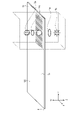
- FIG. 1 is a cross-sectional view (b) of a three-dimensional display body according to the present embodiment, a plan view (a) showing a first region and a first contour region, and a second region and a second contour It is a plan view (c) showing a region.
- FIG. 1A is a cross-sectional view (a) of the three-dimensional display shown in FIG. It is sectional drawing (b) of a display body.
- FIG. 1B is a cross-sectional view showing an example of the positional relationship between the laminate sheet and the adhesion region.
- FIG. 2 is a cross-sectional view (a) showing an example of the detailed configuration on the upper surface side in FIG. 1(b), a plan view (b) identical to FIG.
- FIG. 2A corresponds to FIGS. 2(a) and 2(c), and the first element cell and the second cell shown in FIGS.
- FIG. 10 is a cross-sectional view showing a configuration covered with .
- FIG. 2B is a cross-sectional view showing another example of the positional relationship between the laminate sheet and the adhesion region.
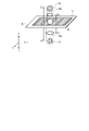
- FIG. 3 is a perspective view showing a state in which a reproduced image is reproduced separately from the front and back surfaces of the authentication body.
- 3A is a perspective view showing the positional relationship of each reproduced image in FIG. 3.
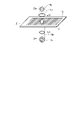
- FIG. FIG. 4 is a diagram showing a reproduced image when the authentication body shown in FIG.
- FIG. 3 is inverted. 4A is a perspective view showing the positional relationship of each reproduced image in FIG. 4.
- FIG. FIG. 5 is a diagram for explaining a method of forming a three-dimensional structure of a three-dimensional display.
- FIG. 6 is a diagram for explaining a method of forming a three-dimensional structure of a three-dimensional display.
- FIG. 7A is a diagram for explaining a method of forming a three-dimensional structure of a three-dimensional display.
- FIG. 7B is a diagram for explaining a method of forming a three-dimensional structure of a three-dimensional display.
- FIG. 8A is a diagram for explaining a method of forming a three-dimensional structure of a three-dimensional display.
- FIG. 8B is a diagram for explaining a method of forming a three-dimensional structure of a three-dimensional display.
- FIG. 9 is a diagram showing an example of a passport produced by transferring a three-dimensional hologram foil to the front and back of a transparent window portion.
- FIG. 10 is a diagram for explaining the phase angle recording area for recording the phase calculated by the CGH.
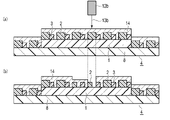
- FIG. 11 is a cross-sectional view (a) of the laminate before the three-dimensional display is included, and a cross-sectional view (b) of the laminate including the three-dimensional display.
- FIG. 1 is a cross-sectional view (b) of a three-dimensional display body according to the present embodiment, a plan view (a) showing a first region and a first contour region, and a second region and a second contour It is a plan view (c) showing a region.
- FIG. 2(a) is a cross-sectional view showing a detailed configuration example of the upper surface side in FIG. 1(b)
- FIG. 2(c) is a cross-sectional view showing a detailed configuration example of the lower surface side in FIG. 1(b).
- 2(b) is the same plan view as FIG. 1(a)
- FIG. 2(d) is the same plan view as FIG. 1(c).
- FIG. 3 is a perspective view showing a state in which a reproduced image is reproduced separately from each of the front and back surfaces of the authentication body.
- FIG. 3 shows a first reproduced image 7a and a reproduced image 11b of the second outline area recorded in the first area 5 and the second outline area 10 of the three-dimensional display body 4 according to the present embodiment. 3 shows a state in which the second reproduced image 7b and the reproduced image 11a of the first outline area recorded in the second area 6 and the first outline area 9 are reproduced from the rear side, respectively.
- the three-dimensional display 4 As shown in the cross-sectional view of FIG. 1B, the three-dimensional display 4 according to the present embodiment has a plurality of first element cells 2 and second element cells 3 on laminate sheets 1a and 1b. will be placed. A laminate sheet 8 is sandwiched between the laminate sheet 1a and the laminate sheet 1b.
- Personal identification information such as biometric information is recorded in the first element cell 2 .
- the second element cell 3 contains an authenticator with which personal identification information can be visually recognized.
- the three-dimensional display 4 has a first region 5 formed by arranging a plurality of first element cells 2 and second element cells 3 (in a top plan view corresponding to FIG. 1B). 1(a)) and a second region 6 (see FIG. 1(c) which is a bottom plan view corresponding to FIG. 1(b)).
- a phase shift structure is formed in each of the first element cell 2 and the second element cell 3 .
- the three-dimensional display 4 has hologram foils 21 and 22 with corresponding patterns on the front and back of a transparent base material such as a laminate sheet 8 with high accuracy.
- a transparent base material such as a laminate sheet 8 with high accuracy.
- An image can also be formed by demetallizing a portion of the front or back surface by laser ablation. As a result, even if there is a slight misalignment between the hologram foil 21 on the front side and the hologram foil 22 on the back side, it can be visually recognized at a glance. .
- FIG. 2(a) is a cross-sectional view showing a detailed configuration example of the upper surface side in FIG. 1(b)
- FIG. 2(c) is a cross-sectional view showing a detailed configuration example of the lower surface side in FIG. 1(b). be.
- the first element cells 2 and the second element cells 3 are nested at a predetermined ratio. arranged in a shape. This forms a three-dimensional structure.
- the first region 5 and the second region 6 arranged in the three-dimensional structure form an integrated cubic region where the reproduction point group by the reflected light of the phase shift structure is consistent.
- An original image is formed and can be viewed from different sides of the laminate sheet 8 .
- the first area 5 is visible from the upper middle of FIG. 1(b)
- the second area 6 is visible from the lower middle of FIG. 1(b).
- Consistency can be defined as the area where one pattern does not contain the other pattern. Consistent means that the patterns on the front and back of the sheet form one motif. Motifs can be letters, symbols, signs and decorations.
- a first character for example, a face
- this character is surrounded by a first outline area 9. .
- a second character for example, the sun
- this character is surrounded by a second outline area 10.
- the first contour region 9 and the second contour region 10 also form phase shift structures by arranging a plurality of first element cells 2 and second element cells 3, respectively.
- the first element cell 2 and the second element cell 3 are A three-dimensional structure is formed by arranging them in a nested manner at a predetermined ratio.
- the first outline area 9 and the second outline area 10 are visible from different sides of the laminate sheet 8 .
- the first contour region 9 is visible from the surface side, which is the upper side in the figure, and can be seen from FIGS. 1(b) and 1(c).
- the second outline region 10 is visible from the back side, which is the lower side in the figure.
- phase shift structure formed in the first element cell 2 As shown in FIG. 2 is reproduced.
- phase shift structure formed in the second element cell 3 a first outline region is formed on the second surface (for example, the back surface, which is the lower side in the drawing) of the laminate sheet 8, spaced apart from the laminate sheet 1b. is reproduced.
- the first reconstructed image 7a and the reconstructed image 11b of the second contour area can be reconstructed so as to overlap each other on the upper side in FIG. Only one of the first reconstructed image 7a and the reconstructed image 11b of the second contour region lacks a three-dimensional effect.
- the three-dimensional display 4 can reproduce the first reproduced image 7a and the reproduced image 11b of the second contour area so as to overlap each other, the observer can feel a doubled sense of depth.
- a portion of the surface formed by the point group of the first region 5 and a portion of the surface formed by the point group of the second region 6 may be parallel. As a result, it is possible to display a multi-layered composite image.
- the second reconstructed image 7b and the reconstructed image 11a of the first contour area can be reconstructed so as to overlap each other on the lower side of FIG. Only one of the second reconstructed image 7b and the reconstructed image 11a of the first contour region lacks a three-dimensional effect. However, since the three-dimensional display 4 can reproduce the second reproduced image 7b and the reproduced image 11a of the first outline area so as to overlap each other, the observer can feel a doubled sense of depth. A portion of the surface formed by the point group of the first contour region 9 and a portion of the surface formed by the point group of the second contour region 10 may be parallel. This makes it possible to display a reproduced image that is multi-layered and combined.
- a first region 5 for reproducing the first reproduced image 7a and a second region 6 composed of diffraction gratings for diffracting light with different pitches and azimuth angles in specific directions. can be arranged adjacently within the three-dimensional display 4 .
- the first areas 5 may each have a plurality of phase angle recording areas.
- the second area 6 may also have a plurality of phase angle recording areas with different recorded diffraction grating pitches, azimuth angles, or both.
- the phase angle recording area will be described later with reference to FIG.
- the three-dimensional display 4 aligns the markers 19 with the first outline area 9 and the second outline area 10 composed of a diffraction grating that diffracts light with different pitches and azimuth angles in specific directions. form adjacently arranged contours 20 .
- the first contour area 9 may also have a phase angle recording area, which will be described later.
- the second contour area 10 may also have a phase angle recording area, described below, in which the pitch of the diffraction grating recorded, the azimuth angle, or both are different.
- the area of the first region 5 and the first contour region 9 can be the same as or larger than the area of the second region 6 and the second contour region 10 .
- the first region 5 and the first contour region 9 and the second region 6 and the second contour region 10 can be arranged adjacent to each other with a predetermined gap.
- the brightness of the reproduced images 7a, 7b, 11a, and 11b becomes darker depending on the area of the phase angle recording area, which will be described later. Therefore, by changing the areas of the first element cells 2 and the second element cells 3 in the first area 5, the first outline area 9, the second area 6, and the second outline area 10, the luminance can be adjusted.
- the first element cell 2 and the second element cell 3 are separated from each other at a distance at which an observer can see them at the same time, They can be spaced apart via spacers, for example nested at a fixed ratio.
- the constant ratio can be the ratio between the number of first element cells 2 and the number of second element cells 3 within a unit area of a computational element partition, which will be described later.
- the first element cell 2 and the second element cell 3 can be of the same size.
- the first element cell 2 and the second element cell 3 can have the same shape.
- the size of the first element cell 2 and the second element cell 3 can be 5 ⁇ m or more and 150 ⁇ m or less. This size can be the length of the short sides of the first element cell 2 and the second element cell 3 . It can also be the length of the short side of the rectangle that circumscribes the first element cell 2 and the second element cell 3 .
- FIG. 1A(a) is a cross-sectional view of the three-dimensional display 4 shown in FIG. 1(b) covered with a single-layer or multilayer reflective layer 14.
- FIG. 1A(a) is a cross-sectional view of the three-dimensional display 4 shown in FIG. 1(b) covered with a single-layer or multilayer reflective layer 14.
- FIG. 2A(a) corresponds to FIGS. 2(a) and 2(c), and the first element cell 2 and the second element cell 3 shown in FIGS. 2(a) and 2(c) are unitized.
- FIG. 4 is a cross-sectional view showing a configuration covered with a layer or multiple layers of reflective layer 14;
- 3A is a perspective view showing the positional relationship of the reproduced images 7a, 7b, 11a, and 11b in FIG.
- the first distance Z1 indicates the distance from the first surface of the laminate sheet 1a (for example, the upper surface in the figure) to the first reproduced image 7a.
- a second distance Z2 indicates the distance from the second surface of the laminate sheet 1b (for example, the lower surface in the figure) to the second reproduced image 7b.
- a third distance Z3 indicates the distance from the second surface of the laminate sheet 1b (for example, the lower surface in the figure) to the reproduced image 11a of the first contour area.
- a fourth distance Z4 indicates a distance from the first surface (for example, the upper surface in the figure) of the laminate sheet 1a to the reproduced image 11b of the second contour area.
- the relationships are Z1 ⁇ Z2 and Z4 ⁇ Z3.
- FIG. 4 is a diagram showing a reproduced image reproduced when the authentication body 100 shown in FIG. 3 is inverted.
- 4A is a perspective view showing the positional relationship between the reproduced images 7a, 7b, 11a, and 11b in FIG.
- FIG 3 and 4 show a first reconstructed image 7a and a second reconstructed image 7b recorded as a structure having a phase shift function between the first region 5 and the second region 6, observed under illumination light. shows what you can do.
- the first reconstructed image 7a and the second reconstructed image 7b recorded as a structure having a phase shift function in the phase angle recording area, which will be described later, are reproduced by illumination.
- the first reconstructed image 7a, the second reconstructed image 7b, the reconstructed image 11a of the first contour area, and the reconstructed image 11b of the second contour area are composed of a plurality of reconstruction points.
- the first reconstructed image 7a, the second reconstructed image 7b, the reconstructed image 11a of the first outline area, and the reconstructed image 11b of the second outline area are displayed as a group of reconstruction points.
- the first reconstructed image 7a represents the face and the second reconstructed image 7b represents the sun. That is, the first reconstructed image 7a and the second reconstructed image 7b may be different. Also, the sizes of the first reconstructed image 7a and the second reconstructed image 7b may be the same or different. For example, the ratio of the areas of the convex hulls of the first reconstructed image 7a and the second reconstructed image 7b can be 1:2 or more and 2:1 or less.
- the size of the first reconstructed image 7a can be made smaller than the size of the second reconstructed image 7b.
- the ratio of the areas of the convex hulls of the first reconstructed image 7a and the second reconstructed image 7b can be 1:10 or more and less than 1:2.
- the first reproduced image 7a is reproduced on the front side of the observer, that is, the front side
- the second reproduced image 7b is reproduced on the back side of the observer.
- FIG. 4 shows the situation on the back side, and the manifestation situation is opposite to the manifestation situation as in FIG. 3 described above.
- the reproduced image 11a of the first contour area is shown in white characters on a black background
- the reproduced image 11b of the second contour area is shown in black characters on a white background. That is, the reconstructed image 11a of the first outline area and the reconstructed image 11b of the second outline area may be different. Further, the reconstructed image 11a of the first outline area and the reconstructed image 11b of the second outline area may be of the same size.
- the ratio of the areas of the convex hulls of the reconstruction image 11a of the first contour region and the reconstruction image 11b of the second contour region is It can be 1:2 or more and 2:1 or less.
- the size of the reconstructed image 11a of the first contour region can be made smaller than the size of the reconstructed image 11b of the second contour region.
- the ratio of the areas of the convex hulls of the reconstructed image 11a of the first contour region and the reconstructed image 11b of the second contour region can be 1:10 or more and less than 1:2.
- the reproduced image 11b of the second contour area is reproduced on the front side, that is, the front side of the observer, and the reproduced image 11a of the first contour area is reproduced on the observer's side. It is played backwards.
- FIG. 4 shows the situation on the back side, and the manifestation situation is opposite to the manifestation situation as in FIG. 3 described above.
- the reproduced image 11b of the contour area of No. 2 is separated from the three-dimensional display body 4 and reproduced in space.
- the structure having a phase shift function reproduces planar reproduced images 7a, 7b, 11a, 11b in space.
- the shape of the reproduced images 7a, 7b, 11a, and 11b can also be curved.
- the stereoscopic effect obtained by the observer is the reproduction distance of the reproduced images, that is, the distance between the centers of the reproduced images 7a, 7b, 11a, and 11b and the surface of the three-dimensional display 4 (Z1, Z2, Z3, Z4).
- the three-dimensional display 4 reproduces the reproduced images 7a, 7b, 11a, and 11b in the space on the front side and the space on the back side of the three-dimensional display 4, respectively. This makes it possible to increase the three-dimensional effect while suppressing blurring of the reproduced images 7a, 7b, 11a, and 11b.
- the reproduction distance Z1 from the three-dimensional display 4 to the first reproduction image 7a is different from the reproduction distance Z2 from the three-dimensional display 4 to the reproduction image 7b. shows an example in which two reproduced images 7a, 7a are reproduced in the direction opposite to that in FIG.
- FIG. 3A shows an example in which the reproduced images 11b and 11b of the first and second outline regions are reproduced on different sides of the three-dimensional display 4, and FIG. 4A shows the three-dimensional display shown in FIG. 3A. 4 is turned upside down, and reproduced images 11a and 11b of the first and second outline regions are reproduced on the opposite side of FIG. 3A.
- Z2 ⁇ Z1. have a relationship of Further, unlike the reproduction distance Z3 from the three-dimensional display 4 to the reproduced image 11a of the first contour area and the reproduction distance Z4 from the three-dimensional display 4 to the reproduced image 11b of the second contour area, Z4 ⁇ It has a relationship of Z3.
- FIG. 4A shows a state in which the three-dimensional display body 4 shown in FIG. 3A is viewed from the back side.
- the relation of ⁇ Z4 is established.
- the three-dimensional display 4 may be constructed so as to reproduce all of the first reproduced image 7a and the second reproduced image 7b on the front side, or conversely, on the back side. can also be constructed so as to reproduce all of the first reproduced image 7a and the second reproduced image 7b on the front side, or conversely, on the back side. can also be constructed so as to reproduce all of the first reproduced image 7a and the second reproduced image 7b on the front side, or conversely, on the back side. can also be constructed so as to reproduce all of the first reproduced image 7a and the second reproduced image 7b on the front side, or conversely, on the back side. can also be constructed so as to reproduce all of the first reproduced image 7a and the second reproduced image 7b on the front side, or conversely, on the back side. can also be constructed so as to reproduce all of the first reproduced image 7a and the second reproduced image 7b on the front side, or conversely, on the back side. can also be constructed so as to reproduce all
- the three-dimensional display 4 is configured so that the reproduced image 11a of the first contour area and the reproduced image 11b of the second contour area are all reproduced on the front side, or vice versa.
- the first reproduced image 7a and the second contour region reproduced image 11b can be visually recognized.
- the reproduced images 7a and 11b become blurred and cannot be visually recognized, while only the second reproduced image 7b and the reproduced image 11a of the first contour area are visually recognized. become able to.
- the first reconstructed image 7a and the reconstructed image 11a of the first contour area are clearly distinguished even if the values of the reconstruction distances Z2 and Z3 and the viewing angle are increased. can be visually recognized. Also, the second reconstructed image 7b and the reconstructed image 11b of the second outline area can be clearly visually recognized. Therefore, the sense of depth can be visually recognized by comparing the first reconstructed image 7a and the second reconstructed image 7b.
- a structure with a phase shift function that reproduces a reproduction point calculates the phase in the structure with a phase shift function by CGH from the optical distance and wavelength of the reproduction point, and shifts the phase of the incident light corresponding to the phase.
- a structure having a phase shift function is recorded in the phase angle recording areas (described later) of the first area 5, the first contour area 9, the second area 6, and the second contour area 10. be.
- a structure having a phase shift function can be recorded as a relief structure or as a modulation of the refractive index in the phase angle recording area described later.
- phase difference When recording the phase difference as a relief structure, it is done as follows. First, a resist plate coated with an electron beam resist on a glass plate is exposed to an electron beam with a dose corresponding to the phase shift amount, and the resist plate is developed to form an uneven surface corresponding to the phase shift amount. Next, a master plate is produced by depositing a metal layer on the uneven surface formed on the resist plate. The nickel shim is then replicated from the master plate by electroforming. By embossing the replicated shim onto a resin-on-carrier film, the relief structure can be recorded in the resin. Thus, a structure having a phase shift function recorded as a relief structure is excellent for mass production.
- the resin embossing the relief structure can be a thermoplastic resin, a curable resin, or a composite of both resins.
- a composite of a thermoplastic resin and a curable resin can record a phase with high accuracy as a relief structure, so that reproduction points can be recorded with high density, and the three-dimensional display 4 on which the relief structure is recorded can be obtained. , it has high tampering resistance because it can be destroyed when it is heated and peeled off from the adherend for tampering.
- a one-sided relief structure is created that includes a first region 5, a first contour region 9, a second region 6 and a second contour region 10.
- the first region 5, the first contour region 9, the second region 6, and the second create two relief structures consisting of one surface including the outline area 10 of , adhere the two relief structures while aligning these two relief structures with respective markers 19, and cut the margins including the markers, Alternatively, it can be achieved by demetalizing, removing, and leaving as a pattern.
- FIGS. 5 and 6, FIGS. 7A and 7B, and FIGS. 8A and 8B a method of forming a three-dimensional structure of the three-dimensional display 4 will be described with reference to FIGS. 5 and 6, FIGS. 7A and 7B, and FIGS. 8A and 8B.
- FIGS. 5 and 6, FIGS. 7A and 7B, and FIGS. 8A and 8B are diagrams for explaining a method of forming a three-dimensional structure of a three-dimensional display.
- the three-dimensional display 4 is irradiated with strong laser light 13a from a laser irradiation device 12a on one side or both sides.
- the first element cells 2 and/or the second element cells 3, which are three-dimensional structures formed of resin, are melted, and the single-layer or multi-layer reflective layer 14 on the laminate sheet 1 evaporates.
- FIG. 5(b), FIG. 7A(b) and FIG. 7B(b) the hologram foil on the front side can be partially demetallized with a laser.
- an infrared laser with a wavelength of 1064 nm, a YVO/YAG laser, a fiber laser, or a CO 2 laser (gas laser) with a wavelength of 10600 nm can be applied.
- the material of the reflective layer 14 can be a metal, a metal compound, or silicon oxide.
- Metal compounds can be metal oxides, metal sulfides, and metal fluorides. These metal compounds are resistant to chemical change and can retain reproduced images recorded in the recording area for a long period of time.
- the metal sulfide can be zinc sulfide.
- the metal oxide can be titanium oxide.
- the metal fluoride can be magnesium fluoride.
- the metal can be aluminum, silver, tin, nickel, chromium, gold, either singly or in alloys. In particular, since aluminum forms a passivation layer, it has high durability and can retain a reproduced image recorded in the recording area for a long period of time.
- a weak laser beam 13b is emitted from a laser irradiation device 12b to one side or both sides to obtain a laser beam shown in FIGS.
- FIGS. 8A(b) and 7B(b) by using materials with different wavelength absorptances, the first element cell 2 and/or the second element cell 3 are left to form a single layer or multiple layers. It is also possible to remove only the reflective layer 14 or to remove only part of the reflective layer 14 .
- a metal compound can be used as a material with different wavelength absorptivity.
- Metal compounds can be zinc sulfide, alumina, titanium oxide. These metal compounds are resistant to chemical change and can retain reproduced images stored in the storage area for a long period of time.
- the effect of the reflective layer 14 can be halved.
- the shape of the reproduced image can be arbitrarily changed or the effect of the reproduced image can be improved. It can also be halved or amplified.
- FIG. 9 is a diagram showing an example of a passport created by transferring a three-dimensional hologram foil to the front and back of the transparent window portion.
- a first face image 41 and a second face image 42 are formed by transferring three-dimensional hologram foil to the front and back of the transparent window portion corresponding to the transparent window portion 23 in FIG. 7A(b). is formed.
- FIG. 10 is a diagram for explaining the phase angle recording area for recording the phase calculated by the CGH.
- the three-dimensional display 4 has a recording surface on the laminate sheet 8 . Pixels are provided on the recording surface, and these pixels are classified into a calculation element section 15, a phase angle recording area 16, and a phase angle non-recording area 17, as described in Patent Document 7.
- a reconstruction image is an image of a plurality of reconstruction points.
- the reproduction point is preferably located at a distance of 5 mm or more and 25 mm or less from the pixel surface in the Z direction.
- the range in which the reproduced image is reproduced in the direction of the viewing angle when the pixel surface is viewed from the reproduction point of interest is called the viewing angle ⁇ .
- the viewing angle direction is the X direction or the Y direction.
- the viewing angle ⁇ from the reproduction point is defined by the following formula (1).
- A asin( ⁇ /2d) (2) is the wavelength of light, d is the arrangement interval of the unit blocks in the viewing angle direction, and m is a real number of 3 or more.
- the wavelength ⁇ of light can be set to 555 nm, which is the maximum relative luminosity of humans in visible light.
- the arrangement interval d can be the center-to-center distance of the unit blocks.
- the arrangement interval d of the unit blocks can be 10 nm or more and 200 nm or less.
- the viewing angle ⁇ is determined by the range in the X direction when the pixel surface is viewed from the reproduction point of interest. is 1/2 of The X direction and the Y direction respectively correspond to the X coordinate axis and the Y coordinate axis of Euclidean coordinates in which one direction in which the pixel surface extends is the X direction and the direction orthogonal to the X direction is the Y direction.
- the viewing angle ⁇ when the viewing angle direction is the Y direction is also defined in the same manner. That is, the viewing angle ⁇ is determined by the range in the Y direction when the relief surface is viewed from the reproduction point of interest, and is defined by the minimum value Ymin in the Y direction, the reproduction point of interest, and the maximum value Ymax in the Y direction. It is 1/2 of the angle 2 ⁇ . Therefore, when the viewing angle direction is the X direction, the unit block arrangement interval d corresponds to the unit block arrangement interval dx in the X direction, and when the viewing angle direction is the Y direction, the first It corresponds to the arrangement interval dy between the element cells 2 and the second element cells 3 in the Y direction.
- the computing element section 15 is generally square or rectangular.
- the computational element section 15 may be a polygon other than a quadrangle, or a circle or an ellipse. Of the polygons, in particular squares, rectangles, but also hexagons are suitable.
- the minimum value (lower limit) of the computational element block 15 in the X direction is Xmin
- the maximum value (upper limit) of the computational element block 15 in the X direction is Let Xmax.
- Ymin be the minimum value of the calculation element section 15 in the Y direction
- Ymax be the maximum value of the calculation element section 15 in the Y direction.
- a unit block When the shape of a unit block is a square or rectangle, it is actually a square or rectangle with rounded corners. Also, a unit block may be merged with an adjacent unit block. In this case, even if the shape of each unit block is a rectangle with rounded corners, the shape of the fused unit blocks will not be a rectangle with rounded corners and will be deformed. does not change.
- the unit blocks are preferably arranged in order. The orderly arrangement may be an arrangement at regular intervals or an arrangement at equal intervals. Typical ordered arrays are square arrays and hexagonal arrays.
- the viewing angle ⁇ is less than A, as is clear from the above formula (1). If light passes through this phase component and is diffracted, in theory no diffraction beyond A will occur. Therefore, when performing hologram calculation using a computer, the upper limit of the calculation range should be the viewing angle ⁇ . By limiting the calculation range in this way, the calculation time can be shortened. Moreover, even if the calculation is performed for a range exceeding the viewing angle ⁇ , the calculation is only for diffraction that does not exist theoretically, and the result only contributes as noise. However, in the above calculation, since the calculation for the range exceeding the viewing angle ⁇ is not performed, noise is not superimposed when the reproduced image is reproduced on the reproduction point.
- Both the phase angle recording area 16 and the phase angle non-recording area 17 each include a plurality of unit blocks.
- the phase angle is calculated by a computer based on the phase component for the unit blocks included in the overlapping area, which is the area overlapping with the calculation element section 15, and the calculated phase angle is Recorded in a unit block included in the overlapping area.
- Computational element sections 15 are respectively defined on the pixel surface in accordance with the viewing angle ⁇ . In this way, the calculation element section 15 is defined independently of the phase angle recording area 16 and the phase angle non-recording area 17. overlaps.
- the calculation element section 15 corresponds to each reproduction point of the reproduced image on a one-to-one basis, and the phase component of light from each reproduction point is calculated. Since there are a plurality of reproduction points, there are also a plurality of calculation element sections 15 which are the same in number as the reproduction points, and the phase component of light from each reproduction point is calculated for each of these plurality of calculation element sections 15 .
- the phase angle recording area 16 is an area capable of recording the phase angle calculated based on the phase component.
- the phase angle non-recording area 17 is an area in which no phase angle is recorded, and is a mirror surface in one example.
- the phase angle is recorded for each calculation element section 15 in an overlapping area where the calculation element section 15 and the phase angle recording area 16 overlap.
- phase angle non-recording area 17 Information other than the phase angle, such as light scattering, reflection, and diffraction characteristics, can be recorded in the phase angle non-recording area 17 .
- FIG. 11 is a cross-sectional view (a) of the layered body 30 before the three-dimensional display body 4 is included, and a cross-sectional view (b) of the layered body 30 with the three-dimensional display body 4 included.
- the overall thickness can be, for example, within the range of 0.18 mm or more and 0.84 mm or less according to JISX6311 and JISX6301 (ISO/IEC7810).
- the laminate 30 includes, from the upper side in the figure, a transparent protective layer 31 which is a transparent outer layer base material, a phase modulation layer 32 which receives illumination light and modulates it, and a transparent intermediate base material which receives laser light and develops color.
- a transparent protective layer 31 which is a transparent outer layer base material
- phase modulation layer 32 which receives illumination light and modulates it
- a transparent intermediate base material which receives laser light and develops color.
- a printed layer 33, a core layer 34 as a core substrate, a printed layer 33, a phase modulation layer 32, and a transparent protective layer 31 are laminated in this order.
- the first area 5 and the second area 6 of the three-dimensional display 4 are visible from outside the laminate 30 .
- the three-dimensional display object 4 By enclosing the three-dimensional display object 4 in the encapsulation portion 25 which is a part of the core layer 34 and is a transparent non-printing portion, the three-dimensional display object 4 is enclosed as shown in FIG. 11(b). A laminated body 30 can be obtained.
- the three-dimensional display 4 can also be formed on a carrier (not shown).
- the three-dimensional representation 4 on a carrier (not shown) can be attached to an adherend (not shown) by hot stamping into the inclusion via adhesive areas 18 as shown in FIGS. 1B and 2B.
- 1B and 2B are cross-sectional views showing an example of the positional relationship between the laminate sheet and the adhesion region.
- the laminate sheet 1 on which the three-dimensional display 4 is arranged is attached, for example, a printed notebook, a printed page, a printed card, etc., via the adhesive area 18 as shown in FIGS. 1B and 2B. Can be attached to the body.
- the adhesive region 18 can also be attached to the adherend by hot stamping.
- the authenticator 100 is a card.
- the card can be an ID card, a license card, or a game card.
- the ID card can be a national ID card, a foreigner residence card, a tax payment card.
- the booklet can be used as a passport.
- a carrier (not shown) can be a plastic film.
- the material of the plastic film can be PET (polyethylene terephthalate), PEN (polyethylene naphthalate), or PP (polypropylene).
- the plastic film may have a coat layer formed by applying a resin.
- the phase modulation layer 32 can be multi-layered.
- the phase modulation layer 32 can have a structure in which an embossed layer, a reflective layer, and a mask layer are laminated in this order. Note that the reflective layer and the mask layer can be omitted.
- the material of the transparent protective layer 31 can be a thermoplastic polymer.
- the material of the embossed layer can be a cured polymer.
- the material of the reflective layer can be inorganic.
- the transparent protective layer 31 and the embossed layer can be formed by coating.
- the reflective layer can be deposited to form a single layer or multiple layers. Deposition can be physical deposition or chemical deposition. Physical deposition can be vacuum evaporation and sputtering.
- the mask layer can be formed by printing ink. Printing can be offset printing, gravure printing, or screen printing.
- the ink can be oil-based ink or water-based ink. Also, the ink may be UV ink.
- the embossed layer can be a single layer or a composite layer.
- the composite layer can consist of a relief layer, an intermediate section and an anchor layer.
- the relief layer can be a cured polymer.
- the anchor layer can be a thermoset polymer.
- the intermediate layer can be a mixture.
- the material of the transparent protective layer 31 can be a mixture of resin and lubricant.
- the resin can be a thermoplastic resin.
- resins can be acrylic resins, polyester resins, polyamide resins, and cellulose resins.
- lubricant polyethylene powder, paraffin wax, silicone, wax such as carnauba wax can be used. These can be formed as a release layer on the substrate layer by a known coating method such as a gravure printing method or a microgravure method.
- the thickness of the release layer can be in the range of 0.5 ⁇ m or more and 5 ⁇ m or less.
- the material of the single-layer embossed layer can be polyacrylate, polyurethane acrylate, or polyacrylic acrylate.
- the material of the relief layer can be polyacrylate, polyurethane acrylate, polyacrylic acrylate.
- the material of the intermediate portion can be a mixture of polyacrylate and polyurethane acrylate.
- the material of the anchor layer can be polyurethane acrylate.
- the transparent protective layer 31, the phase modulation layer 32, the print layer 33, and the core layer 34 in which the three-dimensional display body 4 is enclosed in the encapsulating portion 35 are laminated in this order by heat pressurization, and integrated by thermocompression bonding.
- a laminate 30 as shown in FIG. 11(b) can be formed.
- Laminates 30 can be cards, tags, pages of a booklet. Thereby, a security-labeled authenticator can be formed.
- a reflection scattering layer (not shown), which is an additive element, can also be provided.
- the reflective scattering layer can use functional inks that change color depending on the illumination or viewing angle.
- functional ink for example, optical variable ink, color shift ink and pearl ink can be used.
- the first area 5 can record personal identification data including biometric information.
- the ID card owner's face can be reproduced as the first reproduced image 7a as a color image expressed in two or more colors and having a gradation value for each calculation element section 15 for each color.
- the second area 6 can record other data of personal identification information including biometric information in the first area 5 .
- biometric information for example, hash information related to the ID card owner stored in the first area 5 by having a binarized gradation value for each calculation element section 15 based on the first area 5 can be reproduced as the second reproduced image 7b.
- the first contour area 9 has a gradation value for each calculation element section 15 for each color as color image data expressed in two or more colors. Also, the second outline area 10 has a binarized tone value for each calculation element section 15 based on the first outline area 9 .
- first contour area 9 and the second contour area 10 to record characters of personal identification information including biometric information associated with the first area 5 and the second area 6 .
- the hash information related to the ID card owner recorded in the first area 5 and the second area 6 is reproduced as the reproduced image 11a of the first outline area and the reproduced image 11b of the second outline area. Therefore, it is possible to enhance the designability.
- first contour area 9 and the second contour area 10 can be used for the first area 5 and the second area 6 to prevent forgery.
- the first region 5 and the first outline region 9 are combined, element cells on the region are arranged so as to overlap the two regions, and the counterfeit product is peeled off. It is only necessary to reproduce a reproduced image that can be recognized as a forgery.
- a transparent polycarbonate resin sheet (thickness of 100 ⁇ m) is used, and as the material of the phase modulation layer 32, a transparent polycarbonate resin sheet (thickness of 100 ⁇ m) containing a phase shift structure is used as the material of the printing layer 33.
- a laser coloring polycarbonate resin sheet (100 ⁇ m thick), and a white polycarbonate resin sheet (200 ⁇ m thick) as a material for the core layer 34 .
- the core layer 34 having the three-dimensional display 4 disposed on the portion 25 was laminated in this order, heat-pressed with a plate at 180 degrees, and then cooled. After that, punching was performed to obtain a card of 85 ⁇ 54 mm.
- a plurality of first elements for reproducing a reproduced image 7a representing a facial motif as a group of reproduction points on the front side of the three-dimensional display body 4 at a reproduction distance of Z1 2 mm from the front side of the three-dimensional display body 4.
- a cell 2 and a plurality of reproduced images 7b showing a motif of the sun as a group of reproduction points at a reproduction distance of Z2 2 mm from the back side of the three-dimensional display body 4 on the back side of the three-dimensional display body 4.
- the observer By observing the card to which the three-dimensional display 4 is attached under a point light source, the observer observes the reproduced image of the motif of the face and the reproduced image of the motif of the sun at a distance of 4 mm, thereby obtaining a sense of depth. can feel In addition, under environmental lighting such as a surface light source or indirect lighting, only the reproduced image 7a of the face reproduced at 2 mm from the front surface of the three-dimensional display body 4 was visible on the front side of the three-dimensional display body 4. With this irradiation, a reproduced image 7b of the sun reproduced at 2 mm from the back side of the three-dimensional display 4 was visible on the front side of the three-dimensional display 4. As shown in FIG.
- a master with a relief structure was formed as an uneven surface on the resist plate by electron beam lithography, and after forming a conductive film on the surface of the master by deposition, the shim was replicated by electroforming.
- the three-dimensional display 4 is formed by coating the precursor onto the transparent protective layer 31 so that the thickness after drying becomes 3 ⁇ m, thereby forming an embossed layer.
- a relief structure is formed in the embossed layer by pressing a shim having an uneven surface formed by electroforming on the surface of the embossed layer with heat and UV irradiation, and embossing the uneven surface. .
- a reflective layer of aluminum was formed by vacuum deposition on the surface of the embossed layer on which the relief structure was formed.
- an adhesive was applied onto the reflective layer to form an adhesive layer.
- These coating materials may be diluted with a solvent.
- the laminate 30 containing the three-dimensional display body 4 according to the embodiment of the present invention can be produced satisfactorily.
Abstract
Description
ここで、(λ/2d)≦1である場合、下記の(2)式が得られる。
ただし、λは光の波長、dは単位ブロックの視野角方向における配列間隔、mは3以上の実数である。
Claims (19)
- 個人識別情報が記録された第1の要素セルと、前記個人識別情報を視認可能な認証体を含む第2の要素セルとが、ラミネートシート上に配置されてなる3次元表示体であって、
複数の前記第1の要素セルおよび前記第2の要素セルがそれぞれ配置されることによって形成された、第1の領域と第2の領域とを有し、
前記第1の要素セルと、前記第2の要素セルとに、それぞれ位相シフト構造が形成され、
前記第1の領域および前記第2の領域それぞれにおいて、前記第1の要素セルと前記第2の要素セルとが、スペーサを介して離間して配置されることによって立体構造体が形成され、
前記立体構造体に配置された前記第1の領域および前記第2の領域は、位相シフト構造の反射光による再生点群が一貫性のある一体の三次元像を形成し、
前記第1の要素セルに形成された位相シフト構造により、前記ラミネートシートの第1の面側に、前記ラミネートシートから離間して第1の再生像が再生され、
前記第2の要素セルに形成された位相シフト構造により、前記ラミネートシートの第2の面側に、前記ラミネートシートから離間して第2の再生像が再生されることを特徴とする、3次元表示体。 - 記録された第1のキャラクタを囲む第1の輪郭領域と、記録された第2のキャラクタを囲む第2の輪郭領域とが、ラミネートシート上に配置されてなる3次元表示体であって、
前記第1の輪郭領域および前記第2の輪郭領域には、個人識別情報が記録された複数の第1の要素セルと、前記個人識別情報を視認可能な認証体を含む第2の要素セルとが、それぞれ配置されることによって、それぞれ位相シフト構造が形成され、
前記第1の輪郭領域および前記第2の輪郭領域それぞれにおいて、前記第1の要素セルと前記第2の要素セルとが、所定の比率で入れ子状に配置されることによって立体構造体が形成され、
前記第1の輪郭領域および前記第2の輪郭領域は、前記ラミネートシートのそれぞれ異なる面側から視認可能であり、
前記第1の要素セルに形成された位相シフト構造により、前記ラミネートシートの第1の面側に、前記ラミネートシートから離間して前記第2の輪郭領域の再生像が再生され、
前記第2の要素セルに形成された位相シフト構造により、前記ラミネートシートの第2の面側に、前記ラミネートシートから離間して前記第1の輪郭領域の再生像が再生されることを特徴とする、3次元表示体。 - 請求項1に記載の3次元表示体と、請求項2に記載の3次元表示体とを接続することによって構成されたことを特徴とする、3次元表示体。
- 請求項1に記載の3次元表示体が配置されたラミネートシートに第1のマーカを設け、
請求項2に記載の3次元表示体が配置されたラミネートシートに第2のマーカを設け、
前記第1のマーカと、前記第2のマーカとを用いて、両ラミネートシートを位置合わせすることによって、請求項1に記載の3次元表示体と、請求項2に記載の3次元表示体とを接続したことを特徴とする、請求項3に記載の3次元表示体。 - 請求項1に記載の3次元表示体と、請求項2に記載の3次元表示体とを重ね合わせて接続したことを特徴とする、請求項4に記載の3次元表示体。
- 前記第1の面から、前記第1の再生像までの距離である第1の距離Z1と、前記第2の面から、前記第2の再生像までの距離である第2の距離Z2との間に、Z1<Z2の関係が成立することを特徴とする、請求項1に記載の3次元表示体。
- 前記第1の面から、前記第1の再生像までの距離である第1の距離Z1と、前記第2の面から、前記第2の再生像までの距離である第2の距離Z2との間に、Z1>Z2の関係が成立することを特徴とする、請求項1または5に記載の3次元表示体。
- 前記第2の面から、前記第1の輪郭領域の再生像までの距離である第3の距離Z3と、前記第1の面から、前記第2の輪郭領域の再生像までの距離である第4の距離Z4との間に、Z4<Z3の関係が成立することを特徴とする、請求項2に記載の3次元表示体。
- 前記第2の面から、前記第1の輪郭領域の再生像までの距離である第3の距離Z3と、前記第1の面から、前記第2の輪郭領域の再生像までの距離である第4の距離Z4との間に、Z4>Z3の関係が成立することを特徴とする、請求項2または5に記載の3次元表示体。
- 前記ラミネートシートに記録面を備え、前記記録面に、
前記第1の再生像および前記第2の再生像の各再生点に1対1に対応し、前記各再生点からの光の位相成分が計算される、計算要素区画と、
前記位相成分に基づいて計算された位相角を記録可能な位相角記録領域と、
前記位相角が記録されない位相角非記録領域とを設け、
前記計算要素区画と前記位相角記録領域とが重なる重複領域に、前記位相角を記録することを特徴とする、請求項1に記載の3次元表示体。 - 前記ラミネートシートに記録面を備え、前記記録面に、
前記第1の輪郭領域の再生像および前記第2の輪郭領域の再生像の各再生点に1対1に対応し、前記各再生点からの光の位相成分が計算される、計算要素区画と、
前記位相成分に基づいて計算された位相角を記録可能な位相角記録領域と、
前記位相角が記録されない位相角非記録領域とを設け、
前記計算要素区画と前記位相角記録領域とが重なる重複領域に、前記位相角が記録されることを特徴とする、請求項2に記載の3次元表示体。 - 前記計算要素区画は複数存在し、
前記各再生点からの光の位相成分は、前記複数の計算要素区画の計算要素区画毎に計算され、
前記計算された位相角が、前記計算要素区画毎に記録されることを特徴とする、請求項10または11に記載の3次元表示体。 - 前記位相角非記録領域に、前記位相角以外の情報が記録されることを特徴とする、請求項10乃至12のうち何れか1項に記載の3次元表示体。
- 前記位相角以外の情報は、光の散乱、反射、および回折特性のうちの少なくとも何れかを含む情報であることを特徴とする、請求項13に記載の3次元表示体。
- 前記第1の領域は、2以上の色で表現されるカラー画像のデータとして、階調値を、各色について前記計算要素区画毎に有し、
前記第2の領域は、前記第1の領域に基づいて、二値化された階調値を、前記計算要素区画毎に有する、請求項10に記載の3次元表示体。 - 前記第1の輪郭領域は、2以上の色で表現されるカラー画像のデータとして、階調値を、各色について前記計算要素区画毎に有し、
前記第2の輪郭領域は、前記第1の輪郭領域に基づいて、二値化された階調値を、前記計算要素区画毎に有する、請求項11に記載の3次元表示体。 - 透明な外層基材と、照明光を受けて変調する位相シフト用基材と、レーザ光を受けて発色する透明な中間基材と、コア基材とが積層された積層体を含んでなる認証体であって、
前記コア基材の少なくとも一部に、透明な非印刷部を有し、
前記積層体の中に、請求項1乃至16のうち何れか1項に記載の3次元表示体を内包させたことを特徴とする、認証体。 - 前記3次元表示体の前記第1の領域および前記第2の領域が、前記積層体の外側から視認可能であることを特徴とする、請求項17に記載の認証体。
- 請求項1乃至16のうち何れか1項に記載の3次元表示体における前記立体構造体の形成方法であって、
前記3次元表示体の外部から照射されるレーザ光で、前記第1の要素セルおよび前記第2の要素セルを加工することによって、前記立体構造体を形成することを特徴とする、形成方法。
Priority Applications (4)
| Application Number | Priority Date | Filing Date | Title |
|---|---|---|---|
| EP22820226.3A EP4353487A1 (en) | 2021-06-09 | 2022-06-07 | 3d display, authenticator, and formation method |
| JP2023527877A JPWO2022260047A1 (ja) | 2021-06-09 | 2022-06-07 | |
| KR1020237043153A KR20240019148A (ko) | 2021-06-09 | 2022-06-07 | 3 차원 표시체, 인증체, 및 형성 방법 |
| US18/532,534 US20240100874A1 (en) | 2021-06-09 | 2023-12-07 | Three-dimensional display, authentication medium, and formation method |
Applications Claiming Priority (2)
| Application Number | Priority Date | Filing Date | Title |
|---|---|---|---|
| JP2021096554 | 2021-06-09 | ||
| JP2021-096554 | 2021-06-09 |
Related Child Applications (1)
| Application Number | Title | Priority Date | Filing Date |
|---|---|---|---|
| US18/532,534 Continuation US20240100874A1 (en) | 2021-06-09 | 2023-12-07 | Three-dimensional display, authentication medium, and formation method |
Publications (1)
| Publication Number | Publication Date |
|---|---|
| WO2022260047A1 true WO2022260047A1 (ja) | 2022-12-15 |
Family
ID=84425098
Family Applications (1)
| Application Number | Title | Priority Date | Filing Date |
|---|---|---|---|
| PCT/JP2022/022990 WO2022260047A1 (ja) | 2021-06-09 | 2022-06-07 | 3次元表示体、認証体、および形成方法 |
Country Status (5)
| Country | Link |
|---|---|
| US (1) | US20240100874A1 (ja) |
| EP (1) | EP4353487A1 (ja) |
| JP (1) | JPWO2022260047A1 (ja) |
| KR (1) | KR20240019148A (ja) |
| WO (1) | WO2022260047A1 (ja) |
Citations (5)
| Publication number | Priority date | Publication date | Assignee | Title |
|---|---|---|---|---|
| JPS62283385A (ja) * | 1986-05-31 | 1987-12-09 | Dainippon Printing Co Ltd | カード及びその情報読み取り方法 |
| JP2012144010A (ja) * | 2011-01-14 | 2012-08-02 | Toppan Printing Co Ltd | 偽造防止媒体及び印刷物 |
| WO2017209113A1 (ja) * | 2016-06-03 | 2017-12-07 | 凸版印刷株式会社 | 光学フィルムおよび表示体 |
| WO2020004633A1 (ja) * | 2018-06-29 | 2020-01-02 | 凸版印刷株式会社 | 認証体、認証体の製造方法、認証体の読み取り方法、および認証体の検証方法 |
| JP2021157079A (ja) * | 2020-03-27 | 2021-10-07 | 凸版印刷株式会社 | セキュリティラベル |
Family Cites Families (4)
| Publication number | Priority date | Publication date | Assignee | Title |
|---|---|---|---|---|
| JPH0467683A (ja) | 1990-07-09 | 1992-03-03 | Nippon Telegr & Teleph Corp <Ntt> | 速度変調型電界効果トランジスタ |
| JPH0667592A (ja) | 1992-08-24 | 1994-03-11 | Toppan Printing Co Ltd | 昇華転写画像用透明ホログラム転写箔 |
| JP5589563B2 (ja) | 2010-05-31 | 2014-09-17 | 凸版印刷株式会社 | 立体画像表示体 |
| KR20170020725A (ko) | 2015-07-29 | 2017-02-24 | 주식회사 하이딥 | 압력 전극이 형성된 디스플레이 모듈을 포함하는 터치 입력 장치 및 압력 전극 형성 방법 |
-
2022
- 2022-06-07 KR KR1020237043153A patent/KR20240019148A/ko unknown
- 2022-06-07 JP JP2023527877A patent/JPWO2022260047A1/ja active Pending
- 2022-06-07 WO PCT/JP2022/022990 patent/WO2022260047A1/ja active Application Filing
- 2022-06-07 EP EP22820226.3A patent/EP4353487A1/en active Pending
-
2023
- 2023-12-07 US US18/532,534 patent/US20240100874A1/en active Pending
Patent Citations (5)
| Publication number | Priority date | Publication date | Assignee | Title |
|---|---|---|---|---|
| JPS62283385A (ja) * | 1986-05-31 | 1987-12-09 | Dainippon Printing Co Ltd | カード及びその情報読み取り方法 |
| JP2012144010A (ja) * | 2011-01-14 | 2012-08-02 | Toppan Printing Co Ltd | 偽造防止媒体及び印刷物 |
| WO2017209113A1 (ja) * | 2016-06-03 | 2017-12-07 | 凸版印刷株式会社 | 光学フィルムおよび表示体 |
| WO2020004633A1 (ja) * | 2018-06-29 | 2020-01-02 | 凸版印刷株式会社 | 認証体、認証体の製造方法、認証体の読み取り方法、および認証体の検証方法 |
| JP2021157079A (ja) * | 2020-03-27 | 2021-10-07 | 凸版印刷株式会社 | セキュリティラベル |
Also Published As
| Publication number | Publication date |
|---|---|
| KR20240019148A (ko) | 2024-02-14 |
| US20240100874A1 (en) | 2024-03-28 |
| EP4353487A1 (en) | 2024-04-17 |
| JPWO2022260047A1 (ja) | 2022-12-15 |
Similar Documents
| Publication | Publication Date | Title |
|---|---|---|
| US11623465B2 (en) | Optically variable security element having reflective surface region | |
| US9931883B2 (en) | Image display and labeled device | |
| US5145212A (en) | Non-continuous holograms, methods of making them and articles incorporating them | |
| US5128779A (en) | Non-continuous holograms, methods of making them and articles incorporating them | |
| EP2951029B1 (en) | Security devices and methods of manufacture thereof | |
| CA2777383C (en) | Image display, labeled article, and methods of manufacturing thereof | |
| US20180164478A9 (en) | Film Element | |
| JP6380100B2 (ja) | ホログラム転写箔、画像表示体の作製方法、画像表示体及び個人認証媒体 | |
| JP2001315472A (ja) | 光回折構造を有する情報記録媒体およびカード、並びに光回折構造体 | |
| JP5515713B2 (ja) | 画像表示体、転写箔及び個人認証媒体 | |
| CZ2003252A3 (cs) | Opticky účinná struktura k personalizaci karet a podobně, jakož i způsob jejich výroby | |
| RU2566421C1 (ru) | Многослойное полимерное изделие, такое как идентификационный документ | |
| US11741327B2 (en) | Optical assembly and method of producing optical assembly | |
| WO2022260047A1 (ja) | 3次元表示体、認証体、および形成方法 | |
| JP2012173464A (ja) | 画像形成体の製造方法、画像形成体及び個人認証媒体 | |
| JP2011039336A (ja) | 個人認証媒体 | |
| JP2021157079A (ja) | セキュリティラベル | |
| JP4648150B2 (ja) | 回折格子図柄 | |
| WO2023106240A1 (ja) | 光学構造体およびその製造方法、ならびにコード形成方法 | |
| JP2018187878A (ja) | 偽造防止カード及びその製造方法 |
Legal Events
| Date | Code | Title | Description |
|---|---|---|---|
| 121 | Ep: the epo has been informed by wipo that ep was designated in this application |
Ref document number: 22820226 Country of ref document: EP Kind code of ref document: A1 |
|
| ENP | Entry into the national phase |
Ref document number: 2023527877 Country of ref document: JP Kind code of ref document: A |
|
| WWE | Wipo information: entry into national phase |
Ref document number: 2022820226 Country of ref document: EP |
|
| NENP | Non-entry into the national phase |
Ref country code: DE |
|
| ENP | Entry into the national phase |
Ref document number: 2022820226 Country of ref document: EP Effective date: 20240109 |