WO2022260025A1 - ハロゲン酸素酸の製造方法及びその製造装置 - Google Patents
ハロゲン酸素酸の製造方法及びその製造装置 Download PDFInfo
- Publication number
- WO2022260025A1 WO2022260025A1 PCT/JP2022/022882 JP2022022882W WO2022260025A1 WO 2022260025 A1 WO2022260025 A1 WO 2022260025A1 JP 2022022882 W JP2022022882 W JP 2022022882W WO 2022260025 A1 WO2022260025 A1 WO 2022260025A1
- Authority
- WO
- WIPO (PCT)
- Prior art keywords
- reaction tube
- halogen
- reaction
- liquid
- oxyacid
- Prior art date
- Legal status (The legal status is an assumption and is not a legal conclusion. Google has not performed a legal analysis and makes no representation as to the accuracy of the status listed.)
- Ceased
Links
Images


Classifications
-
- C—CHEMISTRY; METALLURGY
- C07—ORGANIC CHEMISTRY
- C07C—ACYCLIC OR CARBOCYCLIC COMPOUNDS
- C07C209/00—Preparation of compounds containing amino groups bound to a carbon skeleton
- C07C209/68—Preparation of compounds containing amino groups bound to a carbon skeleton from amines, by reactions not involving amino groups, e.g. reduction of unsaturated amines, aromatisation, or substitution of the carbon skeleton
-
- C—CHEMISTRY; METALLURGY
- C07—ORGANIC CHEMISTRY
- C07C—ACYCLIC OR CARBOCYCLIC COMPOUNDS
- C07C211/00—Compounds containing amino groups bound to a carbon skeleton
- C07C211/62—Quaternary ammonium compounds
- C07C211/63—Quaternary ammonium compounds having quaternised nitrogen atoms bound to acyclic carbon atoms
-
- B—PERFORMING OPERATIONS; TRANSPORTING
- B01—PHYSICAL OR CHEMICAL PROCESSES OR APPARATUS IN GENERAL
- B01J—CHEMICAL OR PHYSICAL PROCESSES, e.g. CATALYSIS OR COLLOID CHEMISTRY; THEIR RELEVANT APPARATUS
- B01J19/00—Chemical, physical or physico-chemical processes in general; Their relevant apparatus
- B01J19/02—Apparatus characterised by being constructed of material selected for its chemically-resistant properties
-
- B—PERFORMING OPERATIONS; TRANSPORTING
- B01—PHYSICAL OR CHEMICAL PROCESSES OR APPARATUS IN GENERAL
- B01J—CHEMICAL OR PHYSICAL PROCESSES, e.g. CATALYSIS OR COLLOID CHEMISTRY; THEIR RELEVANT APPARATUS
- B01J19/00—Chemical, physical or physico-chemical processes in general; Their relevant apparatus
- B01J19/24—Stationary reactors without moving elements inside
- B01J19/2415—Tubular reactors
- B01J19/243—Tubular reactors spirally, concentrically or zigzag wound
-
- C—CHEMISTRY; METALLURGY
- C01—INORGANIC CHEMISTRY
- C01B—NON-METALLIC ELEMENTS; COMPOUNDS THEREOF; METALLOIDS OR COMPOUNDS THEREOF NOT COVERED BY SUBCLASS C01C
- C01B11/00—Oxides or oxyacids of halogens; Salts thereof
- C01B11/04—Hypochlorous acid
- C01B11/06—Hypochlorites
-
- B—PERFORMING OPERATIONS; TRANSPORTING
- B01—PHYSICAL OR CHEMICAL PROCESSES OR APPARATUS IN GENERAL
- B01J—CHEMICAL OR PHYSICAL PROCESSES, e.g. CATALYSIS OR COLLOID CHEMISTRY; THEIR RELEVANT APPARATUS
- B01J2219/00—Chemical, physical or physico-chemical processes in general; Their relevant apparatus
- B01J2219/00002—Chemical plants
- B01J2219/00027—Process aspects
- B01J2219/00033—Continuous processes
-
- B—PERFORMING OPERATIONS; TRANSPORTING
- B01—PHYSICAL OR CHEMICAL PROCESSES OR APPARATUS IN GENERAL
- B01J—CHEMICAL OR PHYSICAL PROCESSES, e.g. CATALYSIS OR COLLOID CHEMISTRY; THEIR RELEVANT APPARATUS
- B01J2219/00—Chemical, physical or physico-chemical processes in general; Their relevant apparatus
- B01J2219/00049—Controlling or regulating processes
- B01J2219/00164—Controlling or regulating processes controlling the flow
- B01J2219/00166—Controlling or regulating processes controlling the flow controlling the residence time inside the reactor vessel
-
- B—PERFORMING OPERATIONS; TRANSPORTING
- B01—PHYSICAL OR CHEMICAL PROCESSES OR APPARATUS IN GENERAL
- B01J—CHEMICAL OR PHYSICAL PROCESSES, e.g. CATALYSIS OR COLLOID CHEMISTRY; THEIR RELEVANT APPARATUS
- B01J2219/00—Chemical, physical or physico-chemical processes in general; Their relevant apparatus
- B01J2219/00761—Details of the reactor
- B01J2219/00763—Baffles
- B01J2219/00765—Baffles attached to the reactor wall
- B01J2219/0077—Baffles attached to the reactor wall inclined
- B01J2219/00772—Baffles attached to the reactor wall inclined in a helix
-
- B—PERFORMING OPERATIONS; TRANSPORTING
- B01—PHYSICAL OR CHEMICAL PROCESSES OR APPARATUS IN GENERAL
- B01J—CHEMICAL OR PHYSICAL PROCESSES, e.g. CATALYSIS OR COLLOID CHEMISTRY; THEIR RELEVANT APPARATUS
- B01J2219/00—Chemical, physical or physico-chemical processes in general; Their relevant apparatus
- B01J2219/02—Apparatus characterised by their chemically-resistant properties
- B01J2219/025—Apparatus characterised by their chemically-resistant properties characterised by the construction materials of the reactor vessel proper
- B01J2219/0295—Synthetic organic materials
-
- B—PERFORMING OPERATIONS; TRANSPORTING
- B01—PHYSICAL OR CHEMICAL PROCESSES OR APPARATUS IN GENERAL
- B01J—CHEMICAL OR PHYSICAL PROCESSES, e.g. CATALYSIS OR COLLOID CHEMISTRY; THEIR RELEVANT APPARATUS
- B01J2219/00—Chemical, physical or physico-chemical processes in general; Their relevant apparatus
- B01J2219/18—Details relating to the spatial orientation of the reactor
- B01J2219/182—Details relating to the spatial orientation of the reactor horizontal
Definitions
- the present invention relates to a method for producing an industrially excellent halogen-oxyacid solution by simultaneously supplying an organic alkaline solution and a halogen into a reaction tube, and dissolving them by gas-liquid mixing in the tube.
- Patent Document 1 there is a method of obtaining a liquid having a predetermined concentration by absorbing gas while circulating the liquid in a tank (Patent Document 1). For the purpose of doing this more efficiently, it is also known to adopt a tubular configuration without using a tank as an apparatus. For example, generation of ozonized water by blowing ozone into flowing water (Patent Document 2), or neutralization treatment by blowing carbon dioxide gas into alkaline waste water (Patent Document 3).
- the present invention focuses on the solubility of halogens in organic alkaline solutions, and has come to dissolve them by gas-liquid mixing in a pipe without using a line mixer.
- the structure is not complicated without increasing the size of the device.
- it is possible to provide an industrially superior method and apparatus for producing a halogen-oxyacid solution which has less unreacted halogen, is efficient and has good quality.
- the present inventors have found that while continuously supplying an organic alkaline solution and halogen from one end of a reaction tube to the other end, By alternating and repeating the phase part and the gas phase part, the organic alkaline solution and the halogen are gas-liquid mixed in the liquid phase part and / or the gas phase part, and the halogen oxyacid is industrialized more stably and efficiently.
- the present invention has been completed by discovering a method and a manufacturing apparatus therefor.
- the configuration of the present invention is as follows.
- Item 1 An organic alkaline solution and a halogen are continuously supplied from one end of a reaction tube to the other end, and a liquid phase portion and a gas phase portion are alternately and repeatedly present in a transfer passage of the reaction tube, and the liquid phase portion is and/or a method for producing a halogen oxyacid, comprising a step of gas-liquid mixing an organic alkaline solution and a halogen in a gas phase.
- Item 2. The method for producing a halogen-oxyacid according to Item 1, wherein the volumetric flow rate of the halogen to the volumetric flow rate of the organic alkaline solution supplied to the reaction tube is 1 to 50.
- the method for producing a halogen-oxyacid according to Item 1 or 2 wherein the reaction tube extends in the axial direction while rotating about the axis extending from one end to the other end.
- Item 4. The method for producing a halogen-oxyacid according to any one of Items 1 to 3, wherein the reaction tube is arranged to extend substantially horizontally.
- Item 5. The halogen oxygen according to any one of Items 1 to 4, wherein the reaction tube is a reaction tube formed in a helical shape with the direction extending from one end to the other end as an axis and the axis as a helical axis. Method for producing acid.
- Item 8 Equipped with a reaction tube extending in the axial direction while rotating about the axis extending from one end to the other end, the reaction tube being arranged so that the axis extends in a substantially horizontal direction,
- the organic alkaline solution and the halogen are continuously supplied from the one end to the other end, the liquid phase portion and the gas phase portion are alternately and repeatedly present in the transfer passage of the reaction tube, and the liquid phase portion and/or the gas phase portion are repeatedly
- An apparatus for producing a halogen-oxyacid having a structure in which an organic alkaline solution and a halogen are mixed in a gas-liquid manner in a phase section.
- the halogen according to Item 8 comprising a means for supplying the organic alkaline solution and the halogen to the reaction tube at a ratio of 1 to 50 for the volumetric flow rate of the halogen to the volumetric flow rate of the organic alkaline solution.
- Oxygen production equipment Item 10.
- Item 11 The apparatus for producing a halogen-oxyacid according to any one of Items 8 to 10, wherein the reaction tube is a reaction tube containing a fluororesin.
- Item 13 The apparatus for producing a halogen-oxyacid according to any one of Items 8 to 12, wherein the reaction tube is configured such that the organic alkaline solution has a residence time of 5 seconds to 30 minutes.
- the organic alkaline solution and halogen are continuously supplied, and from the other end of the reaction tube, the reaction liquid containing the generated halogen-oxygen acid is continuously taken out.
- the reaction liquid containing the generated halogen-oxygen acid is continuously taken out.
- gas-liquid mixing occurs frequently, so that the component concentration, pH, etc. of the raw material organic alkaline solution and the produced halogen oxyacid are kept constant in a steady state. As a result, side reactions and the like are suppressed, and a reaction solution having good storage stability can be obtained.
- the effect of shortening the time from the start of the reaction to obtaining a reaction solution with a stable composition can be obtained, the amount of waste liquid generated can also be reduced, so that a halogen oxyacid can be obtained efficiently and stably.
- the continuous supply of raw materials and the continuous extraction of reaction products make it possible to handle industrial mass production.
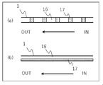
- FIG. 4 is a diagram showing the relationship between operating time and effective chlorine concentration when the manufacturing methods according to the embodiment and comparative example of the present invention are used; 1 is a schematic diagram showing the state of existence of a gas phase portion and a liquid phase portion in a reaction tube, (a) showing a state in which the liquid phase portion and the gas phase portion are alternately repeated in the reaction tube, and (b) ) indicates a state in which the liquid phase portion and the gas phase portion are not alternately repeated in the reaction tube.
- reaction format reaction tube
- one of the features of this embodiment is to use a format in which an organic alkaline solution and a halogen are continuously supplied, and a reaction solution containing the produced halogen-oxyacid is continuously taken out.
- the continuous extraction of the reaction solution containing the halogen-oxyacid is preferably carried out so as to take out an amount corresponding to the amounts of the organic alkaline solution and the halogen that are continuously supplied.
- the corresponding amount means an amount that is the same as or proportional to the total amount of the supplied organic alkali solution and halogen (total amount of organic alkali and halogen>taken amount: both by volume). The same applies to a manufacturing apparatus to be described later.
- the present invention it is preferable to keep constant the amounts of the organic alkaline solution and the produced halogen-oxygen acid, which are the components in the reaction tube in a steady state, and the pH of the reaction liquid taken out from the reaction tube, and to precisely control the supply amount. Adjusting is a preferred mode.
- the process involves adding halogen to an organic alkaline solution charged in a reactor. Oxygen acid decomposition was likely to occur.
- the halogen oxyacid produced in a high pH range there is a problem in storage stability because decomposition products are produced by decomposition of the halogen oxyacid.
- the pH in the present invention is the value at 25°C unless otherwise specified.
- the high pH residence time that causes the maximum side reaction of this reaction. can be reduced. Chlorine gas or chlorine is used as an example of the halogen used, as a result of which a high chlorine yield can be maintained.
- the chlorine yield referred to herein can be obtained from the ratio (%) of the number of moles of hypochlorite ions produced to the number of moles of chlorine molecules supplied to the organic alkaline solution. If all the chlorine added to the organic alkaline solution reacts (no decomposition occurs), the chlorine yield is 100%. If the hypochlorite ions decompose during the reaction, the yield of chlorine will decrease.
- the reaction tube in the present invention means a device in which a chemical reaction is performed in the manufacturing process of a chemical substance. It is preferable to continuously supply the organic alkaline solution and the halogen into the reaction tube at a constant rate. Supplying at a constant rate means that the supply rate is constant. Further, the continuous taking out of the reaction solution does not have to start at the same time as the start of the production method according to the embodiment of the present invention. good.
- the pH of the reaction solution of the organic alkaline solution and the halogen supplied is preferably 10.5 to 14.5. Further, it is more preferable that the pH of the reaction solution of the organic alkaline solution and the halogen is 10.5 to 13.8. Further, it is more preferable that the pH of the reaction solution of the organic alkaline solution and the halogen is 12.0 to 13.8. Further, the pH of the reaction liquid taken out from the reaction tube is preferably 12.0 to 13.8.
- the liquid phase portion and the gas phase portion are alternately and repeatedly present in the transfer path in the transfer direction.
- the liquids can be uniformly stirred and mixed without installing a line mixer for the purpose of the mixing operation in the pipe.
- a line mixer (stirring mixer) is usually employed as a stirring method for uniformizing the fluid passing through the pipe.
- Line mixers are mainly those that mix the fluid by driving the stirring blades installed in the space inside the pipe, or those that mix by passing the fluid through elements fixed in the space inside the pipe, which do not have a driving part.
- An in-line mixer static mixing stirrer
- line mixers are used to efficiently mix fluids, but when it is necessary to generate high-purity liquids that do not like contamination such as particles and metal components, such as semiconductor chemicals, It can be difficult to install a line mixer in the pipe because contamination from the pipe can greatly affect the quality.
- the gas-liquid mixability is poor, resulting in uneven concentration of the reaction liquid in the tube and a short pass of the gas phase, which is disadvantageous as an industrial production method.
- the liquid phase portion and the gas phase portion do not alternately and repeatedly exist in the transfer passage of the reaction tube in the transfer direction, the number and frequency of gas-liquid contact will decrease, and the gas-liquid mixing state in the tube will deteriorate.
- the liquid phase portion and the gas phase portion alternately and repeatedly exist in the transfer passage of the reaction tube.
- the present invention is also characterized in that a liquid having a stable composition can be continuously obtained by replacing the inside of the reaction tube with the reaction liquid only once.
- the volume required for changing the state inside the tube from the pre-reaction organic alkaline solution to the post-reaction liquid is determined by the length from the inlet to the outlet of the reaction tube.
- the simplest method for alternately arranging the liquid phase portion and the gas phase portion within the reaction tube is to set the diameter of the supply pipe for supplying the gas phase and the liquid phase to the same or less than the diameter of the reaction tube. It is to be.
- gas phase portions and liquid phase portions having the same diameter as the reaction tube can be alternately formed on the inlet side of the reaction tube with which the gas and liquid come into contact.
- the liquid-gas ratio value obtained by dividing the volumetric flow rate of the gas phase supplied to the reaction tube per time by the volumetric flow rate of the liquid phase per time supplied to the reaction tube
- the length of the reaction tube As a countermeasure, there is a method of extending the length of the reaction tube to extend the time until the halogen dissolves. It is preferable to stretch the tube while rotating it. That is, it is preferable to extend the reaction tube in the axial direction while rotating about the axis extending from one end of the reaction tube to the other end.
- the axial direction mentioned here preferably extends in the horizontal direction rather than in the vertical direction, but this does not limit the axis to the horizontal direction.
- the direction of the extending axis may be inclined in some way, and it is more preferable to extend the reaction tube in a substantially horizontal direction among the inclined axial directions.
- the diameter of rotation required for turning in the axial direction can be determined according to the length of the reaction tube and the strength of the material used. is preferred.
- the reaction tube rotate more than once, the effect of improving the gas-liquid mixing efficiency can be obtained.
- Inside the reaction tube there are basically two phases: a gas phase that rises due to the buoyancy generated according to the volume of the gas, and a liquid phase that descends due to gravity. It is possible to obtain the effect that the gas phase always comes into contact with the accumulated liquid phase at least once. For this reason, the greater the number of rotations of the reaction tube, the more advantageous it is for the gas-liquid mixing, and the more the short pass of the gas phase can be prevented.
- the gas phase portion may not exist in the vertical direction lower part in the reaction tube.
- the lengths of the gas phase portion and the liquid phase portion present in the reaction tube in the transfer direction may be uneven.
- the number of revolutions of the swirling reaction tube is preferably formed by 2 or more revolutions, more preferably 5 or more revolutions, and still more preferably 10 or more revolutions.
- the upper limit of rotation speed is usually 50 rotations or less.
- the average inner diameter of the reaction tube is preferably 5 mm or more, more preferably 5 mm or more and 500 mm or less, and still more preferably 10 mm or more and 100 mm or less.
- Appearance of the apparatus that satisfies these apparatus configurations is most preferably a form in which the reaction tube is spirally formed along the axial direction, but the form of the reaction tube is not limited to this. are alternately bent along the axial direction, or processed into a wavy shape along the axial direction. Since the inner diameter and length of the reaction tube affect the volume of the reaction liquid, they are important factors for industrial mass production of the reaction liquid.
- the industrial mass production shown here means the efficient and continuous production of the target reaction liquid by reducing the amount of waste liquid generated, and the production amount is the amount of the liquid occupying the tube volume. It is preferable to be able to produce an amount equal to or more than the volume per hour, more preferably 5 times or more, and still more preferably 100 times or more.
- An inert gas may be supplied to the reaction tube in conjunction with the organic alkaline solution and halogen being continuously supplied into the reaction tube.
- the supply of the inert gas not only causes the liquid phase portion and the gas phase portion to alternately exist in the reaction tube, but is also useful in preventing backflow of the liquid phase portion and the gas phase portion in the system.
- the inert gas refers to a stable gas that is unrelated to the reaction, such as air, nitrogen, argon, helium, etc. Air is preferable from the viewpoint of cost. However, the carbon dioxide contained in the air dissolves in the reaction solution, causing a decrease in pH, and the reaction may cause the generation of impurities, so the use of highly purified inert gas is recommended.
- the volume inside the reaction tube can be changed according to the feed rate of the organic alkaline solution used.
- the liquid retention time is defined as the value obtained by dividing the volume in the reaction tube by the volume of the organic alkaline solution per unit of time supplied to the reaction tube
- the liquid retention time of the organic alkaline solution in the reaction tube is preferably from 5 seconds.
- a reaction tube volume of 30 minutes is a preferred embodiment, more preferably 10 seconds to 5 minutes.
- a liquid having a stable composition can be continuously obtained by replacing the inside of the reaction tube with the reaction liquid only once. This means that the time required to obtain a stable liquid composition is directly linked to the liquid residence time.
- the halogen supply rate is preferably 1 to 50, more preferably 10 to 30, in terms of the ratio of the volumetric flow rate of the halogen to the volumetric flow rate of the organic alkaline solution supplied to the reaction tube.
- the volumetric flow rate of the halogen supplied to the reaction tube is calculated in terms of 0° C. and 1 atm when the halogen is gas.
- the dissolved gas includes nitrogen, oxygen, carbon dioxide, etc., but the dissolved gas to be degassed is not limited to these.
- the reaction tube also includes a cylindrical reaction tube (cylindrical reaction tube), which means that only one opening of the reaction tube is closed. Cylindrical reaction tubes are structurally unsuitable for obtaining a liquid with a stable composition in a short time, which is the effect of the present invention. That is, it is difficult to stabilize the composition of the liquid because it is necessary to separately provide a portion necessary for the reaction tube to circulate the liquid, and it is difficult to replace the liquid in the reaction tube. Therefore, there is no choice but to discard the liquid until it is stabilized, and the present invention, in which the liquid is stabilized by replacing the liquid once, is economically advantageous because the amount of generated waste liquid can be reduced.
- the organic alkali solution supplied to the reaction tube may be either an aqueous solution of organic alkali dissolved in water or a solution of organic alkali dissolved in a non-aqueous solvent.
- the organic alkali solution can be obtained by dissolving an organic alkali in water or a non-aqueous solvent, or by diluting a commercially available organic alkali solution to a desired concentration.
- these water or nonaqueous solvents it is preferable to use water because it is easily available industrially and a high-purity organic alkaline solution is available.
- non-aqueous solvents include known organic solvents capable of dissolving organic alkalis.
- the concentration of the organic alkali solution is not particularly limited, but when the concentration of the organic alkali becomes high, the salt precipitates and becomes solid. Therefore, the concentration of the organic alkali in the organic alkali solution is preferably 0.01 to 30% by mass, more preferably 0.05 to 27.5% by mass, still more preferably 0.1 to 25% by mass.
- the solvent used for the organic alkaline solution an aqueous solution using only water as a solvent may be used, an organic solvent may be mixed and used as a non-aqueous solution, or an aqueous solution and an organic solvent may be mixed. .
- the solvent may be appropriately changed according to the use of the solution containing the halogen-oxyacid.
- the organic alkaline solution is preferably a solution of onium hydroxide.
- onium hydroxide examples include ammonium hydroxide, phosphonium hydroxide, sulfonium hydroxide, iminium hydroxide containing multiple bonds, and water.
- One or more selected from the group consisting of diazonium oxide can be used. Among them, it is more preferable to use an ammonium hydroxide solution containing a large amount of relatively stable compounds.
- the onium hydroxide solution described above is preferably an onium hydroxide aqueous solution.
- the ammonium hydroxide solution described above is preferably a quaternary alkylammonium hydroxide solution.
- the quaternary alkylammonium hydroxide solution is preferably a quaternary alkylammonium hydroxide solution in which the alkyl group independently has 1 to 10 carbon atoms, and water in which the alkyl group independently has 1 to 5 carbon atoms. More preferably, it is a solution of quaternary alkylammonium oxide.
- specific quaternary alkylammonium hydroxides include tetramethylammonium hydroxide, tetraethylammonium hydroxide, tetrabutylammonium hydroxide, choline, and the like. These quaternary alkylammonium hydroxides may be used singly or in combination of two or more.
- the number of carbon atoms of the four alkyl groups contained in the quaternary alkylammonium hydroxide may be the same or different.
- concentration range of the organic alkali in the organic alkali solution supplied to the reactor for example, the concentration range of the organic alkali in the organic alkali solution supplied to the reactor, the pH range of the organic alkali solution, the concentration range of the organic alkali in the reaction solution, etc. Any of the above specific examples of the organic alkali can be used.
- the organic alkaline solution may contain chemical species other than organic alkali.
- the chemical species include halides and halogen-containing organic substances, and more specifically, tetraalkylammonium halides such as tetramethylammonium bromide can be exemplified, but are not limited to these. do not have.
- the organic alkaline solution may be a reaction solution obtained by reacting once with halogen, and may be used again as the organic alkaline solution, or the same halogen or another halogen may be supplied to the solution.
- the pH of the reaction liquid containing the halogen-oxyacid generated in the reaction tube tends to decrease.
- the lower limit of the pH of the raw material organic alkaline solution is 10.5 or higher, preferably 11.0 or higher, more preferably 11.5 or higher, and particularly preferably over 12.0.
- the upper limit of the pH of the organic alkali solution is determined by the concentration of the organic alkali.
- an example of the upper limit of the pH of the organic alkaline solution is 14.5 or less.
- the organic alkaline solution used in the present embodiment has a metal content, specifically sodium, potassium, aluminum, magnesium, iron, nickel, copper, silver, cadmium, and lead, each of which is 0.01 ppb or more. It is preferably 20 ppb or less.
- the metal content in the organic alkaline solution to be used may be less than 0.01 ppb, but it is difficult to obtain such an organic alkaline solution.
- the metal Impurities can be easily removed/reduced.
- the metal is eluted from the portion of the reaction tube that is in contact with the organic alkaline solution, it is preferable to provide a reaction tube with a small contact area. That is, a reaction tube with a small volume is an important factor for reducing impurities, and works very effectively in terms of quality control as well.
- the liquid contact area is preferably 0.01 m 2 or more and 10 m 2 or less, more preferably 0.1 m 2 or more and 1.0 m 2 or less.
- a commercially available organic alkaline solution as described above can be used.
- an organic alkaline solution used as a photoresist developer for semiconductor elements which is highly purified by an electrolytic method and/or brought into contact with an ion-exchange resin or the like, can be preferably used.
- These commercially available products can be used after being diluted with a solvent such as ultrapure water that does not contain metal impurities.
- the feed rate of the organic alkaline solution used is preferably from 33 mL/min to 12 L/min, more preferably from 0.2 L/min, when the volume of the reaction tube is 1 L. 6 L/min.
- reaction that occurs when organic alkaline solution and halogen are brought into contact For example, when a quaternary alkylammonium hydroxide is used as the organic alkali, the hydroxide ion of the quaternary alkylammonium hydroxide is generated by contacting and reacting the solution with a halogen to generate hypochlorite generated by the halogen. Replaced with chlorate ions to form a quaternary alkylammonium hypohalite solution.
- the halogen to be used is not particularly limited, and commercially available halogens can be adopted.
- halogen examples include chlorine, bromine, iodine, hypochlorous acid, hypobromous acid, hypoiodous acid, chlorous acid, bromous acid, iodous acid, chloric acid, bromic acid, or iodic acid. can be mentioned. If chlorine or bromine is used, those gases can be used. Among these, it is preferable to use chlorine gas.
- a quaternary alkylammonium hydroxide solution is used as the organic alkaline solution, chlorine gas is used as the halogen, and a method of contacting them will be described as an example of the embodiment of the present invention. In the following explanation, it may be assumed that a quaternary alkylammonium hydroxide solution is used as the organic alkaline solution and chlorine gas is used as the halogen, but this is only an example.
- the pH of the liquid phase during the reaction in this embodiment is preferably 10.5 or higher.
- the liquid phase portion is the portion occupied by the reaction liquid produced by mixing the quaternary alkylammonium hydroxide solution and chlorine gas during the reaction.
- the upper limit of the pH of the liquid phase is not particularly limited, but if the pH during the reaction is excessively high and stored at the same pH for a long time after the completion of the reaction, the hypochlorite ions will be decomposed and the available chlorine concentration will decrease. Sometimes. Therefore, the pH of the liquid phase during the reaction is preferably from 10.5 to 14.5, more preferably from 10.5 to 13.8, and even more preferably from 12 to 13.8. If the pH is within the above range, decomposition of hypochlorite ions is suppressed during storage of the obtained quaternary alkylammonium hypochlorite solution, and storage stability is improved.
- reaction temperature The range of the reaction temperature in the production method of the present embodiment is preferably -35°C or higher and 45°C or lower, more preferably -15°C or higher and 40°C or lower, and even more preferably -5°C or higher and 35°C or lower. If the reaction temperature is within the above range, the organic alkali hydroxide solution and the halogen react sufficiently, and a halogen oxyacid can be obtained in a high yield. If the reaction temperature is lower than ⁇ 35° C., solidification of the organic alkali begins, resulting in insufficient reaction with the halogen.
- the reaction temperature exceeds 45° C.
- the halogen oxyacid ions generated in the halogen oxyacid solution are thermally decomposed.
- the pH during the reaction is 13.8 or higher
- decomposition of the halogen oxyacid becomes significant as the reaction temperature rises.
- the yield of halogen oxyacid can be evaluated by chlorine yield.
- it is possible to produce a halogen oxyacid that has excellent storage stability, for example, that can maintain sufficient cleaning and removal power even after 10 days from production. can be done.
- the halogen oxyacid obtained by the manufacturing method of the present embodiment has excellent storage stability and can be suitably used in the manufacturing process of semiconductor devices.
- the organic alkaline solution and the chlorine gas are brought into contact in a reaction tube to produce a halogen oxyacid.
- a predetermined amount of the organic alkaline solution is introduced into the reaction tube, and then chlorine gas is introduced so as to come into contact with the organic alkaline solution.
- the surface of the reaction tube that comes into contact with the organic alkaline solution (hereinafter sometimes simply referred to as the “inner surface of the reaction tube”) is formed of general-purpose borosilicate glass or an organic polymer material. .
- reaction tube made of general-purpose borosilicate glass (hereinafter referred to as glass)
- metal components contained in the glass such as sodium, potassium, and aluminum
- Slightly soluble in organic alkaline solutions This is considered to be due to the fact that the organic alkaline solution used as the raw material exhibits alkalinity. Therefore, it is more preferable to form the inner surface of the reaction tube with an organic polymer material, thereby further reducing the contamination of impurities containing the above-mentioned metals (metallic impurities).
- the reaction is preferably carried out in a light-shielded environment. Specifically, it is preferable that the inside of the reaction tube is shielded from light.
- the chlorine gas present in the reaction tube may be excited by light to generate chlorine radicals. When chlorine radicals are generated, they may affect the organic alkaline solution present in the reaction tube and the halogen oxyacids produced by the reaction, causing decomposition.
- the halogen oxyacid itself may be decomposed by light, and it is a preferred embodiment that the reaction tube, attached piping, etc. are shielded from light.
- the reactor when an organic solvent is used as the solvent, it is preferable that the reactor has an explosion-proof structure. Therefore, it is preferable that the organic alkaline solution uses water as a solvent in order to simplify the device configuration.
- the organic polymer materials used for the inner surface of the reaction tube include vinyl chloride resins (soft and hard vinyl chloride resins), nylon resins, silicone resins, polyolefin resins (polyethylene, polypropylene), fluorine Resin or the like can be used. Among them, fluororesins are preferable in consideration of the ease of molding, solvent resistance, less elution of impurities, and the like.
- the fluororesin is not particularly limited as long as it is a resin (polymer) containing a fluorine atom, and known fluororesins can be used.
- the method of forming the inner surface of the reaction tube with an organic polymer material includes a method of forming the entire reaction tube with an organic polymer material, and a method of forming only the inner surface of a reaction tube made of glass or stainless steel with an organic polymer material. and the like.
- the organic polymer material may be washed before use in order to prevent elution of metal components from the organic polymer material. Specifically, it is sufficiently washed with an acid such as high-purity nitric acid or hydrochloric acid (for example, washed by being immersed in a solution with an acid concentration of 1 mol/L for 12 hours), and further washed with ultrapure water or the like. preferable.
- the other parts whether glass or stainless steel, are passivated. It may be stainless steel.
- the organic alkaline solution and chlorine gas may be brought into contact in the reaction tube, and the reaction temperature range at that time is not particularly limited, but is the same as the above reaction temperature. is preferred.
- the presence of carbon dioxide in the reaction system tends to lower the pH of the resulting halogen-oxygen acid solution. Therefore, considering stable production, it is preferable not to contain carbon dioxide in the reaction system. Specifically, it is preferable to use an organic alkaline solution, chlorine gas, or the like, in which the amount of carbon dioxide is reduced.
- the production apparatus of the present embodiment includes a reaction tube that extends in the axial direction while rotating about the axis extending from one end to the other end, and the axis of the reaction tube extends in a substantially horizontal direction.
- the organic alkaline solution and the halogen are continuously supplied from the one end to the other end of the reaction tube, and the liquid phase portion and the gas phase portion are alternately and repeatedly present in the transfer passage of the reaction tube.
- the organic alkaline solution and the halogen are mixed in a gas-liquid manner.
- FIG. 1 shows a schematic diagram of a manufacturing apparatus according to this embodiment. The production apparatus shown in FIG.
- reaction tube 1 includes a reaction tube 1, a supply pipe 2 for a quaternary alkylammonium hydroxide solution as means for supplying organic alkali to the reaction pipe, and a pipe for performing the liquid supply operation and stop operation. Equipped with a valve 5, a chlorine gas supply pipe 3 as a halogen supply means, and a pipe valve 6 for performing the chlorine gas supply operation and stop operation, the reaction solution for taking out the reaction solution from the reaction tube to the outside.
- a reaction liquid take-out pipe 8 is provided as take-out means.
- the quaternary alkylammonium hydroxide solution to be supplied is supplied from the quaternary alkylammonium hydroxide solution supply pipe 2, the chlorine gas to be supplied is supplied from the chlorine gas supply pipe 3, Both are supplied continuously.
- a pipe valve 6 is used to supply and stop the chlorine gas. Further, the generated reaction liquid is continuously taken out from the reaction liquid take-out pipe 8 .
- the conditions described in the above manufacturing method can be used as they are for the portion where the quaternary alkylammonium hydroxide solution flows and contacts.
- the inner surface of the reaction tube 1 is preferably made of an organic polymer material.
- the reaction tube is preferably a reaction tube containing a fluororesin, and it is preferable that the reaction tube 1 is wholly or at least composed of a fluororesin.
- the fluororesin may be any of those exemplified in the above "material for the inner surface of the reaction tube”.
- the pipe diameter of the pipe 3 for supplying chlorine and the pipe diameter of the reaction pipe 1 are the same.
- the diameter may be smaller than the tube diameter of the reaction tube 1 .
- the blowing speed of the chlorine gas is preferably 0.1 m/sec or more and 10 m/sec or less in terms of 0° C. and 1 atm.
- the volume inside the reaction tube can be varied according to the feed rate of the quaternary alkylammonium hydroxide solution used.
- the liquid residence time of the quaternary alkylammonium hydroxide solution is A reaction tube volume of preferably 5 seconds to 30 minutes is a preferred embodiment, more preferably 10 seconds to 5 minutes.
- the halogen supply rate is preferably 1 to 50, more preferably 10 to 30, in terms of the ratio of the volumetric flow rate of the halogen to the volumetric flow rate of the organic alkaline solution supplied to the reaction tube.
- the reaction tube extends in the axial direction while rotating about the axis extending from one end to the other end. Further, it is preferable that the reaction tube is arranged so as to extend in a substantially horizontal direction, the reaction tube is a helically formed reaction tube, and the helical axis of the reaction tube is arranged so as to extend in a substantially horizontal direction. is more preferred.
- the diameter of rotation required for swirling (the inner diameter of the helical circle) can be determined according to the length of the reaction tube and the strength of the material used. is preferably The effect of improving gas-liquid mixing can be obtained by rotating the reaction tube one or more times.
- the device is preferably formed by at least two revolutions, more preferably five revolutions or more, and still more preferably ten revolutions or more.
- the upper limit of rotation speed is usually 50 rotations or less. The higher the number of rotations of the reaction tube, the more advantageous the gas-liquid mixing.
- the average inner diameter of the reaction tube it is preferably 5 mm or more, more preferably 5 mm or more and 500 mm or less, and still more preferably 10 mm or more and 100 mm or less.
- the reaction tube 1 may be provided with a nitrogen gas supply pipe 4 as means for supplying nitrogen into the reaction tube 1 in order to adjust the concentration of the gas components supplied to the reaction tube 1 . Further, a piping valve 7 may be provided to perform the operation of supplying and stopping the nitrogen gas.
- the reaction of quaternary alkylammonium hydroxide solution with chlorine is exothermic.
- the temperature inside the reaction tube 1 can be measured using, for example, the reaction liquid temperature measuring device 9 as a means for measuring the temperature in the reaction tube 1 .
- the manufacturing apparatus according to the present embodiment may include a reaction tube temperature control jacket 10 as means for controlling the reaction temperature in the reaction tube, specifically means for removing heat from the reaction tube.
- the production storage according to this embodiment may be provided with a light shielding means in order to carry out the reaction under light shielding conditions.
- the manufacturing apparatus according to the present embodiment may include a reaction liquid pH measuring device 11 arranged in the reaction liquid take-out pipe 8 as a means for measuring the pH of the reaction liquid.
- the measurement solution used for pH measurement causes contamination of the reaction solution, it is more preferable to branch the line for circulation.
- the reaction liquid pH measuring device 11 By using the reaction liquid pH measuring device 11, the pH of the reaction liquid after the reaction can be measured.
- the production apparatus according to the present embodiment preferably includes at least one of the reaction temperature measuring means, the reaction temperature controlling means, and the pH measuring means in the reactor, more preferably two, and further preferably all. preferable.
- a harm removal means may be provided so that unreacted chlorine and the like are not discharged out of the system.
- a caustic soda harm removal device 13 may be installed.
- the structure of the caustic soda abatement device 13 is as follows. A configuration can be used in which the exhaust gas is transferred to the caustic soda detoxification device 13 through the exhaust gas pipe 14 connected to the storage tank and submerged in a solution containing caustic soda. Further, the gas phase portion of the caustic soda detoxification device 13 may be provided with an exhaust gas pipe 15 for discharging detoxified gas.
- ⁇ pH measurement method The pH of 30 mL of the quaternary alkylammonium hydroxide solution and 30 mL of the quaternary alkylammonium hypochlorite solution was measured using a desktop pH meter (LAQUA F-73, manufactured by Horiba, Ltd.). pH measurements were performed after stabilization at 25°C.
- ⁇ Method for calculating effective chlorine concentration and hypochlorite ion concentration In a 100 mL Erlenmeyer flask, 0.5 mL of the treatment liquid (quaternary ammonium hypochlorite solution), 2 g of potassium iodide (manufactured by Fujifilm Wako Pure Chemical Industries, Ltd., reagent special grade), 8 mL of 10% by mass acetic acid, and 10 mL of ultrapure water were added. Add and stir until solids dissolve to give a brown solution.
- the treatment liquid quaternary ammonium hypochlorite solution
- potassium iodide manufactured by Fujifilm Wako Pure Chemical Industries, Ltd., reagent special grade
- the prepared brown solution was subjected to oxidation-reduction titration using a 0.02 M sodium thiosulfate solution (manufactured by Fujifilm Wako Pure Chemical Industries, Ltd., for volumetric analysis) until the color of the solution changed from brown to very pale yellow. solution to obtain a pale purple solution.
- a 0.02M sodium thiosulfate solution was further added to this solution, and the concentration of available chlorine was calculated with the point at which the solution became colorless and transparent as the end point.
- the hypochlorite ion concentration was calculated from the available chlorine concentration thus obtained. For example, if the effective chlorine concentration is 1% by mass, the hypochlorite ion concentration is 0.73% by mass.
- the chlorine yield was obtained from the ratio (%) of the number of moles of hypochlorite ions produced to the number of moles of chlorine molecules supplied to the organic alkaline solution. If all the chlorine added to the organic alkaline solution reacts (no decomposition occurs), the chlorine yield is 100%. If the hypochlorite ions decompose during the reaction, the yield of chlorine will decrease.
- ⁇ Method for evaluating storage stability Transfer the quaternary alkylammonium hypochlorite solution into the glove bag, and after the carbon dioxide concentration in the glove bag is 1 ppm or less, PFA (perfluoroalkoxy fluororesin: tetrafluoroethylene-perfluoroalkyl vinyl ether copolymer ) and sealed.
- PFA perfluoroalkoxy fluororesin: tetrafluoroethylene-perfluoroalkyl vinyl ether copolymer
- a helical reaction tube is formed by rotating a reaction tube made of PFA (inner diameter: 8 mm, length: 1 m), which is a fluororesin, 6 times with a diameter of 50 mm so as to rotate about the horizontal axis. and the reaction tube was installed horizontally.
- a tetramethylammonium hydroxide solution (concentration 12.0% by mass, pH 14.1, liquid temperature 5° C.) was supplied at 370 ml/min and chlorine at 209.8 mmol/min from the inlet side of the reaction tube.
- the reaction solution obtained from (1) was discarded for 1 minute from the start of operation for replacement in the tube, and then continuously sampled for 5 minutes.
- the liquid residence time was 8 seconds, and in the reaction tube, gas phase portions and liquid phase portions alternately existed in the transport direction.
- the unreacted chlorine converted from the effective chlorine concentration in the sodium hydroxide solution (concentration 10 mass%, 1000 ml) for chlorine leakage prevention prepared in the post-process of the reaction tube is equivalent to 100 mass ppm or less of the total chlorine supplied. did.
- a quaternary tetramethylammonium hypochlorite solution (effective chlorine concentration: 3.9% by mass, pH: 13.4, liquid temperature: 17°C) was obtained.
- the chlorine yield was 99% or more and the storage stability was good.
- Example 1 As a comparative example, an experimental example in which the reaction tube in Example 1 is not processed is shown.
- tetramethylammonium hydroxide solution concentration 12.0% by mass, pH 14.1, liquid temperature 5°C
- 209.8 mmol/min of chlorine were supplied from one end of the reaction tube, the inside of the reaction tube was filled with chlorine gas. , the liquid supply became unstable, and the liquid supply decreased to 140 ml/min.
- the liquid residence time was 22 seconds, and the gas phase portion and the liquid phase portion were separated into upper and lower layers in the reaction tube, and did not exist alternately in the transfer direction (see FIG. 3(b)). .
- the reaction liquid obtained from the outlet side of the reaction tube was continuously sampled for 2 minutes.
- the unreacted chlorine converted from the effective chlorine concentration in the sodium hydroxide solution (concentration 10% by mass, 1000 ml) for chlorine leakage prevention prepared in the post-process corresponded to 50% of the total amount of chlorine supplied.
- a quaternary tetramethylammonium hypochlorite solution (effective chlorine concentration: 4.5% by mass, pH: 11.0, liquid temperature: 18°C) was obtained.
- the chlorine yield was 90% and the storage stability was poor.
- Example 2 With the horizontal direction as the axis, a helical reaction tube made of fluororesin PFA (inner diameter: 8 mm, length: 1 m) was rotated three and a half times at a diameter of 100 mm so as to revolve about the axis. The reaction tube was installed horizontally. A tetramethylammonium hydroxide solution (concentration 4.8% by mass, pH 13.7, liquid temperature 5° C.) was supplied at 200 ml/min and chlorine at 12.5 mmol/min from the inlet side of the reaction tube. The reaction solution obtained from (1) was discarded for 1 minute from the start of operation for replacement in the tube, and then continuously sampled for 5 minutes.
- a tetramethylammonium hydroxide solution concentration 4.8% by mass, pH 13.7, liquid temperature 5° C.
- the liquid residence time was 15 seconds, and in the reaction tube, gas phase portions and liquid phase portions alternately existed in the transport direction.
- the unreacted chlorine converted from the effective chlorine concentration in the sodium hydroxide solution (concentration 10 mass%, 1000 ml) for chlorine leakage prevention prepared in the post-process of the reaction tube was equivalent to 500 mass ppm of the total chlorine supplied. .
- a quaternary tetramethylammonium hypochlorite solution (effective chlorine concentration: 0.4% by mass, pH: 13.6, liquid temperature: 6°C) was obtained.
- the chlorine yield was 99% or more and the storage stability was good.
- Example 3 An experimental example in which the reaction tube is not processed in Example 2 is shown.
- a reaction tube (inner diameter: 8 mm, length: 1 m) made of PFA, which is a fluororesin, was extended in a straight tube shape and placed horizontally.
- a tetramethylammonium hydroxide solution (concentration 4.8% by mass, pH 13.7, liquid temperature 7° C.) was supplied from one end of the reaction tube at 200 ml/min, and chlorine was supplied at 12.5 mmol/min. The resulting reaction solution was discarded for 1 minute from the start of operation for replacement in the tube, and then continuously sampled for 5 minutes.
- the liquid residence time was 15 seconds, and in the reaction tube, gas phase portions and liquid phase portions alternately existed in the transport direction (see FIG. 3(a)).
- the unreacted chlorine converted from the effective chlorine concentration in the sodium hydroxide solution (concentration 10% by mass, 1000 ml) for chlorine leakage prevention prepared in the post-process of the reaction tube was equivalent to 5% of the total amount of chlorine supplied.
- a quaternary tetramethylammonium hypochlorite solution (effective chlorine concentration: 0.4% by mass, pH: 13.6, liquid temperature: 8°C) was obtained.
- the chlorine yield was 99% or more and the storage stability was good.
- Example 4 The same spiral reaction tube as used in Example 1 was installed horizontally. A tetramethylammonium hydroxide solution (concentration 25.0% by mass, pH 14.4, liquid temperature 6° C.) was supplied from the inlet side of the reaction tube at 75 ml/min and chlorine was supplied at 75.9 mmol/min, and the outlet side of the reaction tube The reaction solution obtained from (1) was discarded for 1 minute from the start of operation for replacement in the tube, and then continuously sampled for 5 minutes. The liquid residence time was 40 seconds, and in the reaction tube, gas phase portions and liquid phase portions alternately existed in the transport direction.
- the unreacted chlorine converted from the effective chlorine concentration in the sodium hydroxide solution (concentration 10 mass%, 1000 ml) for chlorine leakage prevention prepared in the post-process of the reaction tube is equivalent to 0.2% of the total chlorine supplied. did.
- a quaternary tetramethylammonium hypochlorite solution (effective chlorine concentration: 6.7% by mass, pH: 13.8, liquid temperature: 30°C) was obtained.
- the chlorine yield was 99% or more and the storage stability was good.
- Example 5 An experimental example in which the reaction tube is not processed in Example 4 is shown.
- the same straight tube-shaped reaction tube as used in Comparative Example 1 was installed horizontally.
- a tetramethylammonium hydroxide solution (concentration 25.0% by mass, pH 14.4, liquid temperature 6° C.) was supplied from one end of the reaction tube at 75 ml/min, and chlorine was supplied at 75.9 mmol/min.
- the resulting reaction solution was discarded for 1 minute from the start of operation for replacement in the tube, and then continuously sampled for 5 minutes.
- the liquid residence time was 40 seconds, and in the reaction tube, gas phase portions and liquid phase portions alternately existed in the transport direction.
- the unreacted chlorine converted from the effective chlorine concentration in the sodium hydroxide solution (concentration 10% by mass, 1000 ml) for chlorine leakage prevention prepared in the post-process of the reaction tube was equivalent to 13% of the total amount of chlorine supplied.
- a quaternary tetramethylammonium hypochlorite solution (effective chlorine concentration: 6.0% by mass, pH: 14.0, liquid temperature: 27°C) was obtained.
- the yield of chlorine was 99% or more, and the storage stability was somewhat good.
- a helical reaction tube is formed by rotating a PTFE reaction tube (inner diameter: 11 mm, length: 10 m), which is a fluororesin, 20 times with a diameter of 150 mm so as to rotate about the horizontal axis.
- the reaction tube was placed horizontally in a container filled with cold water to cool the reactor.
- a tetramethylammonium hydroxide solution (concentration 25% by mass, pH 14.4, liquid temperature 5° C.) was supplied at 50 ml/min and chlorine at 68.3 mmol/min from the inlet side of the reaction tube.
- the reaction liquid obtained from the side was discarded for 20 minutes from the start of operation for replacement in the tube, and then continuously sampled for 5 minutes.
- the liquid residence time was 19 minutes, and in the reaction tube, gas phase portions and liquid phase portions alternately existed in the transport direction.
- the unreacted chlorine converted from the effective chlorine concentration in the sodium hydroxide solution (concentration 10% by mass, 1000 ml) for chlorine leakage prevention prepared in the post-process of the reaction tube corresponded to 10 ppm or less of the total amount of chlorine supplied.
- a quaternary tetramethylammonium hypochlorite solution (effective chlorine concentration: 8.8% by mass, pH: 12.0, liquid temperature: 15°C) was obtained.
- the chlorine yield was 99% or more and the storage stability was good.
- Example 7 The same spiral reaction tube as used in Example 6 was installed horizontally. A tetramethylammonium hydroxide solution (concentration 10.0% by mass, pH 14.0, liquid temperature 15° C.) was supplied at 2.5 L/min and chlorine at 1.12 mol/min from the inlet side of the reaction tube. The reaction liquid obtained from the outlet side was continuously sampled after the supply of chlorine was started. The liquid residence time was 20 seconds, and as shown in FIG. 25° C.) was stably obtained. In the reaction tube, gas phase portions and liquid phase portions alternately existed in the direction of transfer.
- a tetramethylammonium hydroxide solution concentration 10.0% by mass, pH 14.0, liquid temperature 15° C.
- the unreacted chlorine converted from the effective chlorine concentration in the sodium hydroxide solution (concentration 10 mass%, 1000 ml) for chlorine leakage prevention prepared in the post-process of the reaction tube is equivalent to 100 mass ppm or less of the total chlorine supplied. did.
- the chlorine yield was 99% or more and the storage stability was good.
- a helical reaction tube is formed by rotating a fluororesin PTFE reaction tube (inner diameter: 11 mm, length: 3 m) six times with a diameter of 150 mm so as to rotate about the horizontal axis. Then, 110 ml/min of a tetramethylammonium hydroxide solution (concentration of 5.0% by mass, pH of 13.7, liquid temperature of 12° C.) and chlorine of 24.3 mmol were added from the inlet side of the reaction tube which was installed horizontally. /min, and the reaction solution obtained from the outlet side of the reaction tube was continuously sampled after the chlorine supply was started. The liquid residence time was 2 minutes, and as shown in FIG. 17° C.) was stably obtained.
- reaction tube gas phase portions and liquid phase portions alternately existed in the direction of transfer.
- the amount of waste liquid generated during the replacement operation until the reaction stabilized was 0.2 L, and the amount of unreacted chlorine was equivalent to 100 mass ppm or less of the total amount of chlorine supplied.
- the gas phase portion and the liquid phase portion were divided into upper and lower layers, and did not exist alternately in the transport direction.
- the amount of waste liquid generated during the replacement operation until the reaction stabilized was 6.7 L, and unreacted chlorine was equivalent to 2% of the total amount of chlorine supplied.
- Example 9 The same spiral reaction tube as used in Example 8 was installed horizontally, and a tetramethylammonium hydroxide solution (concentration 8.5% by mass, pH 14.0, liquid temperature 10 ° C.) was introduced from the inlet side of the reaction tube. was supplied at 1000 ml/min and chlorine at 436 mmol/min. In the reaction tube, gas phase portions and liquid phase portions alternately existed in the direction of transfer.
- Example 3 By the production method of Example 3 in the prior art (International Publication No. 2019/225541), quaternary tetramethylammonium hypochlorite solution (effective chlorine concentration 3.0% by mass, pH 13.0, liquid temperature 5 ° C.) got The reaction time by this manufacturing method was 180 minutes, and the production amount per hour was 0.34 L/H.
- "Liquid-gas ratio" in the table is the ratio of the volumetric flow rate of halogen (chlorine gas) to the volumetric flow rate of the organic alkaline solution (tetramethylammonium hydroxide solution).
- Reaction tube Quaternary alkylammonium hydroxide solution supply line 3 Chlorine gas supply line 4 Nitrogen gas supply line 5 Pipe valve 6 Pipe valve 7 Pipe valve 8 Reaction liquid take-out pipe 9 Reaction liquid temperature measuring device 10 Reaction tube temperature control jacket 11 Reaction liquid pH measurement device 12 Reaction liquid storage tank 13 Caustic soda detoxification device 14 Exhaust gas pipe 15 Exhaust gas pipe 16 Gas phase section 17 Liquid phase section
Landscapes
- Chemical & Material Sciences (AREA)
- Organic Chemistry (AREA)
- Chemical Kinetics & Catalysis (AREA)
- Life Sciences & Earth Sciences (AREA)
- General Life Sciences & Earth Sciences (AREA)
- Geology (AREA)
- Inorganic Chemistry (AREA)
- Organic Low-Molecular-Weight Compounds And Preparation Thereof (AREA)
Priority Applications (4)
| Application Number | Priority Date | Filing Date | Title |
|---|---|---|---|
| CN202280004499.6A CN115916741B (zh) | 2021-06-07 | 2022-06-07 | 卤素含氧酸的制造方法及其制造装置 |
| US17/920,921 US20240116849A1 (en) | 2021-06-07 | 2022-06-07 | Method of manufacturing halogen oxoacid and manufacturing apparatus therefor |
| KR1020227039831A KR20240018343A (ko) | 2021-06-07 | 2022-06-07 | 할로겐산소산의 제조 방법 및 그 제조 장치 |
| JP2023527864A JPWO2022260025A1 (https=) | 2021-06-07 | 2022-06-07 |
Applications Claiming Priority (2)
| Application Number | Priority Date | Filing Date | Title |
|---|---|---|---|
| JP2021094936 | 2021-06-07 | ||
| JP2021-094936 | 2021-06-07 |
Publications (1)
| Publication Number | Publication Date |
|---|---|
| WO2022260025A1 true WO2022260025A1 (ja) | 2022-12-15 |
Family
ID=84425002
Family Applications (1)
| Application Number | Title | Priority Date | Filing Date |
|---|---|---|---|
| PCT/JP2022/022882 Ceased WO2022260025A1 (ja) | 2021-06-07 | 2022-06-07 | ハロゲン酸素酸の製造方法及びその製造装置 |
Country Status (6)
| Country | Link |
|---|---|
| US (1) | US20240116849A1 (https=) |
| JP (1) | JPWO2022260025A1 (https=) |
| KR (1) | KR20240018343A (https=) |
| CN (1) | CN115916741B (https=) |
| TW (1) | TW202313454A (https=) |
| WO (1) | WO2022260025A1 (https=) |
Citations (8)
| Publication number | Priority date | Publication date | Assignee | Title |
|---|---|---|---|---|
| JPS63100927A (ja) * | 1986-04-03 | 1988-05-06 | ヴアーテク トリートメント システムズ インコーポレイテツド | 制御された化学反応を行わせる方法及び反応装置 |
| JPH01274835A (ja) * | 1988-04-28 | 1989-11-02 | Quantum Technol Inc | 気体と液体との連続反応方法および装置 |
| JP2005227749A (ja) * | 2004-02-11 | 2005-08-25 | Mallinckrodt Baker Inc | ハロゲン酸素酸、その塩及び誘導体含有、マイクロエレクトロニクス洗浄組成物 |
| JP2007105668A (ja) * | 2005-10-14 | 2007-04-26 | Mitsubishi Chemicals Corp | 気液反応方法及びそのための装置 |
| JP2012192383A (ja) * | 2011-03-18 | 2012-10-11 | Mitsubishi Rayon Co Ltd | 化合物の製造方法 |
| JP2019098275A (ja) * | 2017-12-05 | 2019-06-24 | 大陽日酸株式会社 | フロー式反応装置 |
| WO2019225541A1 (ja) * | 2018-05-23 | 2019-11-28 | 株式会社トクヤマ | 次亜塩素酸第4級アルキルアンモニウム溶液、その製造方法および半導体ウエハの洗浄方法 |
| JP2022008214A (ja) * | 2020-06-25 | 2022-01-13 | 株式会社トクヤマ | ハロゲン酸素酸溶液の製造方法及び製造装置 |
Family Cites Families (7)
| Publication number | Priority date | Publication date | Assignee | Title |
|---|---|---|---|---|
| JPS53118278A (en) | 1977-03-25 | 1978-10-16 | Daiwa Kikai Seisakusho | Reaction apparatus |
| US4744956A (en) * | 1986-02-12 | 1988-05-17 | Quantum Technologies, Inc. | Continuous reaction of gases with liquids |
| US4869833A (en) * | 1986-04-03 | 1989-09-26 | Vertech Treatment Systems, Inc. | Method and apparatus for controlled chemical reactions |
| JP2005021798A (ja) | 2003-07-01 | 2005-01-27 | Teeiku Wan Sogo Jimusho:Kk | オゾン水製造方法、オゾン水製造装置 |
| JP4360501B1 (ja) | 2009-03-25 | 2009-11-11 | 日本▲まき▼線工業株式会社 | オゾン水生成装置及びオゾン水生成方法 |
| KR102769981B1 (ko) * | 2019-11-22 | 2025-02-18 | 가부시끼가이샤 도꾸야마 | 차아염소산 제 4 급 알킬암모늄 용액, 그 제조 방법 및 반도체 웨이퍼의 처리 방법 |
| CN112410805A (zh) * | 2020-12-14 | 2021-02-26 | 浙江大学 | 管状推流式次氯酸钠发生器 |
-
2022
- 2022-06-07 CN CN202280004499.6A patent/CN115916741B/zh active Active
- 2022-06-07 WO PCT/JP2022/022882 patent/WO2022260025A1/ja not_active Ceased
- 2022-06-07 JP JP2023527864A patent/JPWO2022260025A1/ja active Pending
- 2022-06-07 US US17/920,921 patent/US20240116849A1/en active Pending
- 2022-06-07 KR KR1020227039831A patent/KR20240018343A/ko active Pending
- 2022-06-07 TW TW111120983A patent/TW202313454A/zh unknown
Patent Citations (8)
| Publication number | Priority date | Publication date | Assignee | Title |
|---|---|---|---|---|
| JPS63100927A (ja) * | 1986-04-03 | 1988-05-06 | ヴアーテク トリートメント システムズ インコーポレイテツド | 制御された化学反応を行わせる方法及び反応装置 |
| JPH01274835A (ja) * | 1988-04-28 | 1989-11-02 | Quantum Technol Inc | 気体と液体との連続反応方法および装置 |
| JP2005227749A (ja) * | 2004-02-11 | 2005-08-25 | Mallinckrodt Baker Inc | ハロゲン酸素酸、その塩及び誘導体含有、マイクロエレクトロニクス洗浄組成物 |
| JP2007105668A (ja) * | 2005-10-14 | 2007-04-26 | Mitsubishi Chemicals Corp | 気液反応方法及びそのための装置 |
| JP2012192383A (ja) * | 2011-03-18 | 2012-10-11 | Mitsubishi Rayon Co Ltd | 化合物の製造方法 |
| JP2019098275A (ja) * | 2017-12-05 | 2019-06-24 | 大陽日酸株式会社 | フロー式反応装置 |
| WO2019225541A1 (ja) * | 2018-05-23 | 2019-11-28 | 株式会社トクヤマ | 次亜塩素酸第4級アルキルアンモニウム溶液、その製造方法および半導体ウエハの洗浄方法 |
| JP2022008214A (ja) * | 2020-06-25 | 2022-01-13 | 株式会社トクヤマ | ハロゲン酸素酸溶液の製造方法及び製造装置 |
Also Published As
| Publication number | Publication date |
|---|---|
| KR20240018343A (ko) | 2024-02-13 |
| US20240116849A1 (en) | 2024-04-11 |
| CN115916741A (zh) | 2023-04-04 |
| JPWO2022260025A1 (https=) | 2022-12-15 |
| TW202313454A (zh) | 2023-04-01 |
| CN115916741B (zh) | 2025-08-08 |
Similar Documents
| Publication | Publication Date | Title |
|---|---|---|
| JP7303268B2 (ja) | 次亜塩素酸第4級アルキルアンモニウム溶液 | |
| JP7050184B2 (ja) | ルテニウムの半導体用処理液及びその製造方法 | |
| US11390577B2 (en) | Quaternary alkyl ammonium hypochlorite solution, method of producing the same, and method for processing semiconductor wafers | |
| JP7797124B2 (ja) | ハロゲン酸素酸溶液の製造方法及び製造装置 | |
| US20250313466A1 (en) | Method for producing halogen oxyacid solution | |
| WO2022260025A1 (ja) | ハロゲン酸素酸の製造方法及びその製造装置 | |
| CN116529421A (zh) | 半导体晶片处理液及其制造方法 | |
| WO2025143006A1 (ja) | 次亜臭素酸第四級アルキルアンモニウム溶液の製造方法及び半導体ウエハの処理方法 | |
| JP7663793B1 (ja) | 半導体用処理液、及び低毒性半導体用処理液として用いる方法 | |
| Alibegic et al. | Oxidation of tetrachloroethylene in a bubble column photochemical reactor applying the UV/H2O2 technique |
Legal Events
| Date | Code | Title | Description |
|---|---|---|---|
| 121 | Ep: the epo has been informed by wipo that ep was designated in this application |
Ref document number: 22820204 Country of ref document: EP Kind code of ref document: A1 |
|
| WWE | Wipo information: entry into national phase |
Ref document number: 2023527864 Country of ref document: JP |
|
| NENP | Non-entry into the national phase |
Ref country code: DE |
|
| 122 | Ep: pct application non-entry in european phase |
Ref document number: 22820204 Country of ref document: EP Kind code of ref document: A1 |
|
| WWG | Wipo information: grant in national office |
Ref document number: 202280004499.6 Country of ref document: CN |