WO2022255455A1 - 車両制御装置、車両制御方法、及び車両制御システム - Google Patents
車両制御装置、車両制御方法、及び車両制御システム Download PDFInfo
- Publication number
- WO2022255455A1 WO2022255455A1 PCT/JP2022/022517 JP2022022517W WO2022255455A1 WO 2022255455 A1 WO2022255455 A1 WO 2022255455A1 JP 2022022517 W JP2022022517 W JP 2022022517W WO 2022255455 A1 WO2022255455 A1 WO 2022255455A1
- Authority
- WO
- WIPO (PCT)
- Prior art keywords
- vehicle
- wheel
- driving force
- control
- moment
- Prior art date
- Legal status (The legal status is an assumption and is not a legal conclusion. Google has not performed a legal analysis and makes no representation as to the accuracy of the status listed.)
- Ceased
Links
Images









Classifications
-
- B—PERFORMING OPERATIONS; TRANSPORTING
- B62—LAND VEHICLES FOR TRAVELLING OTHERWISE THAN ON RAILS
- B62D—MOTOR VEHICLES; TRAILERS
- B62D6/00—Arrangements for automatically controlling steering depending on driving conditions sensed and responded to, e.g. control circuits
- B62D6/002—Arrangements for automatically controlling steering depending on driving conditions sensed and responded to, e.g. control circuits computing target steering angles for front or rear wheels
- B62D6/003—Arrangements for automatically controlling steering depending on driving conditions sensed and responded to, e.g. control circuits computing target steering angles for front or rear wheels in order to control vehicle yaw movement, i.e. around a vertical axis
-
- B—PERFORMING OPERATIONS; TRANSPORTING
- B60—VEHICLES IN GENERAL
- B60G—VEHICLE SUSPENSION ARRANGEMENTS
- B60G17/00—Resilient suspensions having means for adjusting the spring or vibration-damper characteristics, for regulating the distance between a supporting surface and a sprung part of vehicle or for locking suspension during use to meet varying vehicular or surface conditions, e.g. due to speed or load
- B60G17/015—Resilient suspensions having means for adjusting the spring or vibration-damper characteristics, for regulating the distance between a supporting surface and a sprung part of vehicle or for locking suspension during use to meet varying vehicular or surface conditions, e.g. due to speed or load the regulating means comprising electric or electronic elements
- B60G17/016—Resilient suspensions having means for adjusting the spring or vibration-damper characteristics, for regulating the distance between a supporting surface and a sprung part of vehicle or for locking suspension during use to meet varying vehicular or surface conditions, e.g. due to speed or load the regulating means comprising electric or electronic elements characterised by their responsiveness, when the vehicle is travelling, to specific motion, a specific condition, or driver input
- B60G17/0162—Resilient suspensions having means for adjusting the spring or vibration-damper characteristics, for regulating the distance between a supporting surface and a sprung part of vehicle or for locking suspension during use to meet varying vehicular or surface conditions, e.g. due to speed or load the regulating means comprising electric or electronic elements characterised by their responsiveness, when the vehicle is travelling, to specific motion, a specific condition, or driver input mainly during a motion involving steering operation, e.g. cornering, overtaking
- B60G17/0163—Resilient suspensions having means for adjusting the spring or vibration-damper characteristics, for regulating the distance between a supporting surface and a sprung part of vehicle or for locking suspension during use to meet varying vehicular or surface conditions, e.g. due to speed or load the regulating means comprising electric or electronic elements characterised by their responsiveness, when the vehicle is travelling, to specific motion, a specific condition, or driver input mainly during a motion involving steering operation, e.g. cornering, overtaking the control involving steering geometry, e.g. four-wheel steering
-
- B—PERFORMING OPERATIONS; TRANSPORTING
- B60—VEHICLES IN GENERAL
- B60G—VEHICLE SUSPENSION ARRANGEMENTS
- B60G17/00—Resilient suspensions having means for adjusting the spring or vibration-damper characteristics, for regulating the distance between a supporting surface and a sprung part of vehicle or for locking suspension during use to meet varying vehicular or surface conditions, e.g. due to speed or load
- B60G17/06—Characteristics of dampers, e.g. mechanical dampers
-
- B—PERFORMING OPERATIONS; TRANSPORTING
- B60—VEHICLES IN GENERAL
- B60W—CONJOINT CONTROL OF VEHICLE SUB-UNITS OF DIFFERENT TYPE OR DIFFERENT FUNCTION; CONTROL SYSTEMS SPECIALLY ADAPTED FOR HYBRID VEHICLES; ROAD VEHICLE DRIVE CONTROL SYSTEMS FOR PURPOSES NOT RELATED TO THE CONTROL OF A PARTICULAR SUB-UNIT
- B60W10/00—Conjoint control of vehicle sub-units of different type or different function
- B60W10/04—Conjoint control of vehicle sub-units of different type or different function including control of propulsion units
-
- B—PERFORMING OPERATIONS; TRANSPORTING
- B60—VEHICLES IN GENERAL
- B60W—CONJOINT CONTROL OF VEHICLE SUB-UNITS OF DIFFERENT TYPE OR DIFFERENT FUNCTION; CONTROL SYSTEMS SPECIALLY ADAPTED FOR HYBRID VEHICLES; ROAD VEHICLE DRIVE CONTROL SYSTEMS FOR PURPOSES NOT RELATED TO THE CONTROL OF A PARTICULAR SUB-UNIT
- B60W10/00—Conjoint control of vehicle sub-units of different type or different function
- B60W10/12—Conjoint control of vehicle sub-units of different type or different function including control of differentials
- B60W10/16—Axle differentials, e.g. for dividing torque between left and right wheels
-
- B—PERFORMING OPERATIONS; TRANSPORTING
- B60—VEHICLES IN GENERAL
- B60W—CONJOINT CONTROL OF VEHICLE SUB-UNITS OF DIFFERENT TYPE OR DIFFERENT FUNCTION; CONTROL SYSTEMS SPECIALLY ADAPTED FOR HYBRID VEHICLES; ROAD VEHICLE DRIVE CONTROL SYSTEMS FOR PURPOSES NOT RELATED TO THE CONTROL OF A PARTICULAR SUB-UNIT
- B60W10/00—Conjoint control of vehicle sub-units of different type or different function
- B60W10/18—Conjoint control of vehicle sub-units of different type or different function including control of braking systems
-
- B—PERFORMING OPERATIONS; TRANSPORTING
- B60—VEHICLES IN GENERAL
- B60W—CONJOINT CONTROL OF VEHICLE SUB-UNITS OF DIFFERENT TYPE OR DIFFERENT FUNCTION; CONTROL SYSTEMS SPECIALLY ADAPTED FOR HYBRID VEHICLES; ROAD VEHICLE DRIVE CONTROL SYSTEMS FOR PURPOSES NOT RELATED TO THE CONTROL OF A PARTICULAR SUB-UNIT
- B60W10/00—Conjoint control of vehicle sub-units of different type or different function
- B60W10/20—Conjoint control of vehicle sub-units of different type or different function including control of steering systems
-
- B—PERFORMING OPERATIONS; TRANSPORTING
- B60—VEHICLES IN GENERAL
- B60W—CONJOINT CONTROL OF VEHICLE SUB-UNITS OF DIFFERENT TYPE OR DIFFERENT FUNCTION; CONTROL SYSTEMS SPECIALLY ADAPTED FOR HYBRID VEHICLES; ROAD VEHICLE DRIVE CONTROL SYSTEMS FOR PURPOSES NOT RELATED TO THE CONTROL OF A PARTICULAR SUB-UNIT
- B60W10/00—Conjoint control of vehicle sub-units of different type or different function
- B60W10/22—Conjoint control of vehicle sub-units of different type or different function including control of suspension systems
-
- B—PERFORMING OPERATIONS; TRANSPORTING
- B60—VEHICLES IN GENERAL
- B60W—CONJOINT CONTROL OF VEHICLE SUB-UNITS OF DIFFERENT TYPE OR DIFFERENT FUNCTION; CONTROL SYSTEMS SPECIALLY ADAPTED FOR HYBRID VEHICLES; ROAD VEHICLE DRIVE CONTROL SYSTEMS FOR PURPOSES NOT RELATED TO THE CONTROL OF A PARTICULAR SUB-UNIT
- B60W30/00—Purposes of road vehicle drive control systems not related to the control of a particular sub-unit, e.g. of systems using conjoint control of vehicle sub-units
- B60W30/02—Control of vehicle driving stability
- B60W30/025—Control of vehicle driving stability related to comfort of drivers or passengers
-
- B—PERFORMING OPERATIONS; TRANSPORTING
- B60—VEHICLES IN GENERAL
- B60W—CONJOINT CONTROL OF VEHICLE SUB-UNITS OF DIFFERENT TYPE OR DIFFERENT FUNCTION; CONTROL SYSTEMS SPECIALLY ADAPTED FOR HYBRID VEHICLES; ROAD VEHICLE DRIVE CONTROL SYSTEMS FOR PURPOSES NOT RELATED TO THE CONTROL OF A PARTICULAR SUB-UNIT
- B60W30/00—Purposes of road vehicle drive control systems not related to the control of a particular sub-unit, e.g. of systems using conjoint control of vehicle sub-units
- B60W30/02—Control of vehicle driving stability
- B60W30/045—Improving turning performance
-
- B—PERFORMING OPERATIONS; TRANSPORTING
- B60—VEHICLES IN GENERAL
- B60W—CONJOINT CONTROL OF VEHICLE SUB-UNITS OF DIFFERENT TYPE OR DIFFERENT FUNCTION; CONTROL SYSTEMS SPECIALLY ADAPTED FOR HYBRID VEHICLES; ROAD VEHICLE DRIVE CONTROL SYSTEMS FOR PURPOSES NOT RELATED TO THE CONTROL OF A PARTICULAR SUB-UNIT
- B60W30/00—Purposes of road vehicle drive control systems not related to the control of a particular sub-unit, e.g. of systems using conjoint control of vehicle sub-units
- B60W30/18—Propelling the vehicle
- B60W30/18009—Propelling the vehicle related to particular drive situations
- B60W30/18145—Cornering
-
- B—PERFORMING OPERATIONS; TRANSPORTING
- B60—VEHICLES IN GENERAL
- B60G—VEHICLE SUSPENSION ARRANGEMENTS
- B60G17/00—Resilient suspensions having means for adjusting the spring or vibration-damper characteristics, for regulating the distance between a supporting surface and a sprung part of vehicle or for locking suspension during use to meet varying vehicular or surface conditions, e.g. due to speed or load
- B60G17/015—Resilient suspensions having means for adjusting the spring or vibration-damper characteristics, for regulating the distance between a supporting surface and a sprung part of vehicle or for locking suspension during use to meet varying vehicular or surface conditions, e.g. due to speed or load the regulating means comprising electric or electronic elements
- B60G17/016—Resilient suspensions having means for adjusting the spring or vibration-damper characteristics, for regulating the distance between a supporting surface and a sprung part of vehicle or for locking suspension during use to meet varying vehicular or surface conditions, e.g. due to speed or load the regulating means comprising electric or electronic elements characterised by their responsiveness, when the vehicle is travelling, to specific motion, a specific condition, or driver input
- B60G17/0165—Resilient suspensions having means for adjusting the spring or vibration-damper characteristics, for regulating the distance between a supporting surface and a sprung part of vehicle or for locking suspension during use to meet varying vehicular or surface conditions, e.g. due to speed or load the regulating means comprising electric or electronic elements characterised by their responsiveness, when the vehicle is travelling, to specific motion, a specific condition, or driver input to an external condition, e.g. rough road surface, side wind
-
- B—PERFORMING OPERATIONS; TRANSPORTING
- B60—VEHICLES IN GENERAL
- B60G—VEHICLE SUSPENSION ARRANGEMENTS
- B60G2400/00—Indexing codes relating to detected, measured or calculated conditions or factors
- B60G2400/05—Attitude
- B60G2400/051—Angle
- B60G2400/0511—Roll angle
-
- B—PERFORMING OPERATIONS; TRANSPORTING
- B60—VEHICLES IN GENERAL
- B60G—VEHICLE SUSPENSION ARRANGEMENTS
- B60G2400/00—Indexing codes relating to detected, measured or calculated conditions or factors
- B60G2400/05—Attitude
- B60G2400/051—Angle
- B60G2400/0513—Yaw angle
-
- B—PERFORMING OPERATIONS; TRANSPORTING
- B60—VEHICLES IN GENERAL
- B60G—VEHICLE SUSPENSION ARRANGEMENTS
- B60G2400/00—Indexing codes relating to detected, measured or calculated conditions or factors
- B60G2400/05—Attitude
- B60G2400/052—Angular rate
- B60G2400/0521—Roll rate
-
- B—PERFORMING OPERATIONS; TRANSPORTING
- B60—VEHICLES IN GENERAL
- B60G—VEHICLE SUSPENSION ARRANGEMENTS
- B60G2400/00—Indexing codes relating to detected, measured or calculated conditions or factors
- B60G2400/05—Attitude
- B60G2400/052—Angular rate
- B60G2400/0523—Yaw rate
-
- B—PERFORMING OPERATIONS; TRANSPORTING
- B60—VEHICLES IN GENERAL
- B60G—VEHICLE SUSPENSION ARRANGEMENTS
- B60G2400/00—Indexing codes relating to detected, measured or calculated conditions or factors
- B60G2400/20—Speed
- B60G2400/204—Vehicle speed
-
- B—PERFORMING OPERATIONS; TRANSPORTING
- B60—VEHICLES IN GENERAL
- B60G—VEHICLE SUSPENSION ARRANGEMENTS
- B60G2400/00—Indexing codes relating to detected, measured or calculated conditions or factors
- B60G2400/20—Speed
- B60G2400/208—Speed of wheel rotation
-
- B—PERFORMING OPERATIONS; TRANSPORTING
- B60—VEHICLES IN GENERAL
- B60G—VEHICLE SUSPENSION ARRANGEMENTS
- B60G2400/00—Indexing codes relating to detected, measured or calculated conditions or factors
- B60G2400/25—Stroke; Height; Displacement
- B60G2400/252—Stroke; Height; Displacement vertical
-
- B—PERFORMING OPERATIONS; TRANSPORTING
- B60—VEHICLES IN GENERAL
- B60G—VEHICLE SUSPENSION ARRANGEMENTS
- B60G2400/00—Indexing codes relating to detected, measured or calculated conditions or factors
- B60G2400/40—Steering conditions
- B60G2400/41—Steering angle
-
- B—PERFORMING OPERATIONS; TRANSPORTING
- B60—VEHICLES IN GENERAL
- B60G—VEHICLE SUSPENSION ARRANGEMENTS
- B60G2401/00—Indexing codes relating to the type of sensors based on the principle of their operation
- B60G2401/14—Photo or light sensitive means, e.g. Infrared
- B60G2401/142—Visual Display Camera, e.g. LCD
-
- B—PERFORMING OPERATIONS; TRANSPORTING
- B60—VEHICLES IN GENERAL
- B60G—VEHICLE SUSPENSION ARRANGEMENTS
- B60G2401/00—Indexing codes relating to the type of sensors based on the principle of their operation
- B60G2401/16—GPS track data
-
- B—PERFORMING OPERATIONS; TRANSPORTING
- B60—VEHICLES IN GENERAL
- B60G—VEHICLE SUSPENSION ARRANGEMENTS
- B60G2500/00—Indexing codes relating to the regulated action or device
- B60G2500/10—Damping action or damper
Definitions
- the present invention relates to a vehicle control device, a vehicle control method, and a vehicle control system.
- the vehicle behavior control device of Patent Document 1 calculates a target longitudinal driving force for driving the vehicle based on the operation state for driving the vehicle by the driver and the motion state generated in the vehicle body during driving of the vehicle.
- the power generation mechanism calculates a plurality of target motion state quantities for controlling the behavior of the vehicle body, and the power generation mechanism controls at least the front wheels and the rear wheels so as to realize the target longitudinal driving force and the plurality of target motion state quantities.
- a driving force or braking force to be generated on one side and a vertical force applied to the vehicle body by a vertical force generating means of the suspension mechanism are calculated, and a signal representing the driving force or the braking force is output to the power generating mechanism.
- a signal representing the vertical force is output to the vertical force generating means.
- the present invention has been made in view of the conventional circumstances, and an object of the present invention is to provide a vehicle control apparatus, a vehicle control method, and a vehicle control system capable of improving the sense of security of passengers when a vehicle travels on a curve. It is to provide a system.
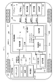
- FIG. 1 is a block diagram showing a vehicle control system
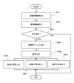
- FIG. 4 is a flow chart showing a procedure of posture control
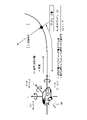
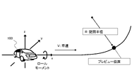
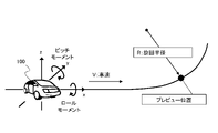
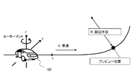
- FIG. 4 is a diagram showing a preview position, curvature, and the like in attitude control
- FIG. 4 is a diagram showing a method of acquiring curvature information from a stereo camera
- FIG. 4 is a diagram showing a method of acquiring curvature information based on vehicle position and map information
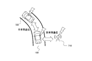
- It is a figure which shows the method of acquiring curvature information by road-to-vehicle communication or vehicle-to-vehicle communication.
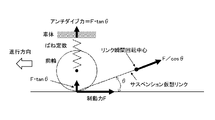
- FIG. 5 is a diagram for explaining that anti-dive force acts on front wheels due to braking force;
- FIG. 5 is a diagram for explaining that anti-dive force acts on front wheels due to braking force;
- FIG. 5 is a diagram for explaining that anti-dive force acts on front wheels due to braking force;
- FIG. 5 is a diagram for explaining that anti-dive force acts on front wheels due to braking
- FIG. 4 is a diagram showing a method of applying a roll moment to a vehicle by controlling longitudinal force
- FIG. 4 is a diagram showing a method of applying a pitch moment to a vehicle by controlling longitudinal force
- It is a figure which shows the method of giving a roll moment to FF vehicle.
- FIG. 4 is a diagram showing a method of applying a roll moment to an FR vehicle
- FIG. 4 is a diagram showing a method of giving a pitch moment to an FR vehicle
- FIG. 4 is a diagram showing a method of applying a yaw moment to a vehicle
- FIG. 4 is a diagram showing damping force control that is performed in parallel with roll moment control;
- FIG. 10 is a diagram showing an example of a damping force adjustment pattern when the control of the roll moment and the control of the pitch moment are linked.
- FIG. 4 is a diagram showing the concept of damping force adjustment according to roll rate and pitch rate;
- FIG. 4 is a diagram showing a method of applying a roll moment to a vehicle body by displacement of a sprung mass;
- FIG. 4 is a diagram showing a method of applying a pitch moment to a vehicle body by displacement of a sprung mass;
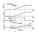
- 4 is a time chart showing changes in roll angle, roll rate, etc. in posture control that produces a roll angle;
- FIG. 10 is a diagram showing a state in which a roll moment is applied to the vehicle in a direction in which the inner wheel of the turn is lifted before the curve.
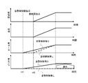
- FIG. 4 is a time chart showing changes in roll angle and the like in attitude control that produces a roll angle in the opposite direction before a curve.
- FIG. 4 is a diagram showing a state in which a reverse roll moment is applied to the vehicle before a curve.
- 4 is a time chart showing changes in pitch angle and the like in posture control for taking a nose dive posture before a curve.
- FIG. 5 is a diagram showing a state in which a pitch moment is applied to the vehicle before a curve; 4 is a time chart showing changes in roll angle, pitch angle, etc. in posture control for taking a diagonal roll posture before a curve.
- FIG. 4 is a time chart showing changes in roll angle and the like in attitude control that produces a roll angle in the opposite direction before a curve.
- FIG. 4 is a diagram showing a state in which a reverse roll moment is applied to the vehicle before a curve.
- 4 is a time chart showing changes in pitch angle and the like in posture control for taking a nose dive posture before a curve.
- FIG. 4 is a diagram showing a state in which a roll moment and a pitch moment are applied to a vehicle in order to take a diagonal roll attitude before a curve; 4 is a time chart showing changes in yaw rate, yaw angle, etc. in attitude control that produces a yaw angle before a curve.
- FIG. 5 is a diagram showing a state in which a yaw moment is applied to the vehicle in order to take a yaw attitude before the curve;
- FIG. 1 is a block diagram showing one aspect of a vehicle control system 200 mounted on a vehicle 100. As shown in FIG.
- the vehicle control system 200 is a system that assists driving such as automatic driving of the vehicle 100 .
- a vehicle 100 is a four-wheel automobile having a pair of left and right front wheels 101 and 102 and a pair of left and right rear wheels 103 and 104 .
- the vehicle control system 200 includes an external world recognition section 300 , a vehicle control device 400 and an actuator section 500 .
- the external world recognition unit 300 is a device for acquiring and recognizing external world information of the vehicle 100, and outputs the acquired and recognized external world information, as well as a vehicle speed command, acceleration command, etc. in automatic driving obtained based on the external world information. do.
- the external world recognition unit 300 includes a stereo camera 310, a navigation device 320, a wireless communication device 330, and the like.
- Stereo camera 310 photographs the surroundings of vehicle 100 to obtain image information of the surroundings of vehicle 100, and measures the distance to an object by triangulation.
- the navigation device 320 has a GPS receiver 321 and a map database 322 .
- GPS receiver 321 measures the latitude and longitude of the position of vehicle 100 by receiving signals from GPS satellites.
- the map database 322 is formed within a storage device mounted on the vehicle 100 .
- the map information in the map database 330 includes information such as road positions, road shapes, and intersection positions.
- the navigation device 320 refers to the map database 330 based on the positional information of the vehicle 100 measured by the GPS receiver 321, identifies the road on which the vehicle 100 is traveling, and also determines the route to the destination of the vehicle 100. set.
- the wireless communication device 330 is a device for implementing road-to-vehicle communication and/or vehicle-to-vehicle communication.
- Road-to-vehicle communication is wireless communication between the vehicle and a roadside device installed on the road
- vehicle-to-vehicle communication is wireless communication between the vehicle and other vehicles.
- the wireless communication device 330 transmits information about its own vehicle, such as speed and travel position, to the roadside device, and receives road traffic information such as curves and intersections, information about other vehicles, and the like from the roadside device. do. Also, in inter-vehicle communication, wireless communication device 330 transmits information about its own vehicle to other vehicles and receives information about the vehicle from other vehicles.
- the vehicle control device 400 is an electronic control device (electronic control unit) provided with a microcomputer 410 as a control section that outputs a result of calculation based on input information.
- the microcomputer 410 has an MPU (Microprocessor Unit), a ROM (Read Only Memory), a RAM (Random Access Memory), etc., which are not shown.
- the microcomputer 410 acquires information on the current position of the vehicle 100, preview information including information on the road ahead of the vehicle 100, a vehicle speed command, an acceleration command, etc. based on the external world recognition from the external world recognition unit 300. Then, the microcomputer 410 calculates a control command for operating the actuator section 500 based on the acquired various information, and outputs the calculated control command to the actuator section 500 .
- the actuator unit 500 includes a driving device 510 that applies driving force to the driving wheels of the vehicle 100, a braking device 520 that applies braking force to the wheels 101 to 104 of the vehicle 100, and damping force adjustment for each of the wheels 101 to 104. It has a suspension device 530 (suspension mechanism) and a steering device 540 that changes the steering angle of the front wheels 101 and 102 that are steered wheels of the vehicle 100 .
- the Drive device 510 is, for example, an in-wheel motor provided for each of wheels 101-104.
- the braking device 520 includes, for example, a hydraulic energy source and can individually adjust the braking force applied to each wheel 101-104 by adjusting the hydraulic pressure supplied to the brake cylinder of each wheel 101-104. It is a braking device.
- Suspension system 530 is, for example, a fully active suspension that has an energy source such as hydraulic pressure or pneumatic pressure and is capable of adjusting damping force and vehicle height, or a semi-active suspension that is capable of adjusting damping force.
- Steering device 540 is, for example, an electric steering device having a motor that generates a steering force for front wheels 101 and 102 .
- the microcomputer 410 of the vehicle control device 400 controls the actuator section 500, in other words, as one of the driving support functions controlled by the actuator section 500, based on the information ahead of the vehicle 100, the vehicle 100 enters a curve. It has a posture control function that controls the posture of the vehicle 100 from the front to a preliminary posture for curve travel. In such attitude control, microcomputer 410 acquires a physical quantity relating to the forward curvature of the road on which vehicle 100 travels, and also acquires a physical quantity relating to the speed of vehicle 100 .
- microcomputer 410 generates a control moment including at least one of a roll moment, a pitch moment, and a yaw moment in vehicle 100 from before the curve based on the physical quantity relating to the forward curvature and the physical quantity relating to speed.
- a control command for operating the actuator section 500 is output. That is, the microcomputer 410 obtains a control moment for the vehicle 100 to take a predetermined preliminary attitude based on the curvature of the front and the speed of the vehicle 100, and drives each of the wheels 101-104 so as to generate the control moment. It controls the force, braking force, or sprung displacement of the suspension 530, and also controls the damping force or steering force (steer angle). It should be noted that microcomputer 410 sets a control command for operating actuator section 500 while obtaining a control moment so that the front, rear, left, and right accelerations generated in vehicle 100 do not change.
- the occupants of the vehicle 100 can recognize in advance that the vehicle 100 will travel on a curve based on the attitude change of the vehicle 100, and can feel a sense of security. .
- the vehicle 100 by causing the vehicle 100 to have a roll angle and a yaw angle before the vehicle 100 enters a curve, the roll angle, roll rate, or yaw rate when the vehicle 100 travels around the curve is reduced, thereby improving the comfort of the occupant. Driving operability is improved.
- the microcomputer 410 has a state estimation section 420 and an integrated control section 430 as main functional sections.
- State estimating section 420 is a functional section that determines the running state and running environment of vehicle 100 , and includes curvature determining section 421 .
- Curvature determination unit 421 obtains information about the curvature of the travel road at the preview position in front of vehicle 100 based on the preview information acquired from external world recognition unit 300, and outputs the information about the obtained curvature.
- the integrated control unit 430 is a functional unit that performs integrated control of driving of the vehicle 100 , and has a vehicle speed control unit 431 and an attitude control unit 432 .
- the vehicle speed control unit 431 controls the vehicle speed and acceleration of the vehicle 100 by controlling the actuator unit 500 based on the vehicle speed command and the acceleration command acquired from the external world recognition unit 300, and outputs information regarding the vehicle speed to the posture control unit 432. do.
- the posture control unit 432 can acquire information about the vehicle speed from a vehicle speed sensor or a wheel speed sensor.
- Posture control unit 432 is a functional unit that controls the posture of vehicle 100 to a preliminary posture for curve travel before vehicle 100 enters a curve, and includes control command calculation unit 432A and distribution control unit 432B.
- Control command calculation unit 432A acquires information about the vehicle speed from vehicle speed control unit 431 and acquires information about the curvature of the travel road at the preview position in front of vehicle 100 from curvature determination unit 421 . Then, the control command calculation unit 432A generates control including at least one of roll moment, pitch moment, and yaw moment in the vehicle 100 from before the curve based on the obtained information about the vehicle speed and the information about the curvature of the travel road. Moment (in other words, moment command value) is obtained.
- the distribution control unit 432B acquires information about the control moment from the control command calculation unit 432A, and outputs a control command for operating the actuator unit 500 to obtain the control moment. That is, in order to generate a control moment, the distribution control unit 432B outputs a driving force command to the driving device 510, outputs a braking force command to the braking device 520, outputs a damping force command to the suspension device 530, and outputs a steering force command. A steering angle command is output to the device 540 .
- FIG. 2 is a flow chart showing the procedure of attitude control by the microcomputer 410. As shown in FIG. Microcomputer 410 periodically executes the routine shown in FIG. 2, for example, with time interrupts.
- the microcomputer 410 acquires the road surface information at the preview position in front of the vehicle 100 from the external world recognition section 300 in step S801.
- step S802 the microcomputer 410 obtains the curvature of the road at the preview position based on the road surface information acquired in step S801.
- the distance [m] which is the distance from the current position of the vehicle 100 to the preview position on the road in front of the vehicle 100, is defined as L, and the vehicle 100 moves from the current position to the current vehicle speed V [km/h].
- t be the time [sec] required to reach the preview position.
- Kv is the curvature of the road at the current position of the vehicle 100 .
- the roll moment is the force that rotates the vehicle body about the X-axis that passes through the center of gravity of the vehicle 100 forward and backward
- the pitch moment is the force that rotates the vehicle body about the Y-axis that passes through the center of gravity of the vehicle 100 from side to side.
- the yaw moment is the force that rotates the vehicle body around the Z-axis that vertically penetrates the center of gravity of the vehicle.
- FIG. 4 to 6 are diagrams exemplifying how the microcomputer 410 (curvature determination unit 421) acquires information on the curvature Kp at the preview position.
- FIG. 4 shows a method for the curvature determination unit 421 to acquire information on the curvature Kp based on the information on the white line recognized from the image of the stereo camera 310 .
- FIG. 5 shows that the curvature determination unit 421 recognizes the vehicle position on the map based on the result of the position measurement of the vehicle 100 by the navigation device 320 and the map information, so that the road curvature information included in the map information is obtained. A method of searching to obtain information on the curvature Kp will be shown.
- FIG. 6 shows a method for the curvature determination unit 421 to acquire curvature Kp information from the roadside device 710 or another vehicle 720 through road-to-vehicle communication or vehicle-to-vehicle communication using the wireless communication device 330 .
- step S803 After obtaining information on the curvature Kp at the preview position in step S802, the microcomputer 410 determines in step S803 whether or not the attitude control start condition is satisfied. In step S803, microcomputer 410 determines whether or not at least one of the following first start condition and second start condition is satisfied.
- the microcomputer 410 determines whether any one of the following third to sixth start conditions is satisfied. to judge.
- ⁇ Third start condition the distance L from the current position to the preview position is equal to or less than the third threshold L3 (L ⁇ L3)
- Fourth start condition the time t required for the vehicle 100 to reach the preview position is equal to or less than the fourth threshold value t4 (t ⁇ t4)
- ⁇ Fifth start condition The steering angle is within a predetermined angle and it is estimated that steering is not started
- ⁇ Sixth start condition The actual yaw rate is within a predetermined range and it is estimated that steering is not started
- Microcomputer 410 starts attitude control when at least one of the first start condition and the second start condition is satisfied and at least one of the third start condition to the sixth start condition is satisfied. It is determined that the start condition is satisfied. In other words, the microcomputer 410 performs attitude control when there is a curve in the road ahead of the vehicle 100 and the vehicle 100 is traveling substantially straight within a predetermined range in front of the curve. . On the other hand, if the conditions for starting attitude control are not met, the microcomputer 410 terminates the process and does not perform attitude control.
- step S804 microcomputer 410 calculates target moments about three axes of vehicle 100 for attitude control, specifically, target roll moment Mx and target pitch moment, based on curvature Kp at the preview position and current vehicle speed V. At least one of My and the target yaw moment Mz is calculated (see FIG. 3).
- Cx, Cy and Cz are control gains for each target moment Mx, My and Mz.
- the control gains Cx, Cy, Cz are adapted based on experiments, simulations, etc. in the design development stage of the vehicle control system 200, and are stored in the memory of the microcomputer 410 as control constants.
- the microcomputer 410 multiplies the difference between the curvature Kp at the preview position and the curvature Kv at the current position and the vehicle speed by the control gain to obtain the target roll moment Mx and the target pitch moment My. , the desired yaw moment Mz. Therefore, the larger the difference between the curvature Kp at the preview position and the curvature Kv at the current position, the greater the control moment, and the higher the vehicle speed V, the greater the control moment.
- microcomputer 410 calculates roll moment Mx to cause vehicle 100 to take a roll posture as a preliminary posture, for example, roll moment Mx is calculated according to curvature Kp and vehicle speed V when vehicle 100 turns into a curve. It increases as it approaches, and the roll angle of the vehicle 100 gradually increases.
- microcomputer 410 obtains the lateral acceleration (estimated lateral acceleration) of vehicle 100 that is estimated to occur at the preview position by Equation 1 based on the curvature Kp at the preview position and the current vehicle speed V. and the control gains Cx1, Cy1, Cz1 of the respective target moments Mx, My, Mz, the target moments Mx, My, Mz can be calculated.
- microcomputer 410 obtains the lateral jerk (estimated lateral jerk) of vehicle 100 that is estimated to occur at the preview position by Equation 2 based on the curvature Kp at the preview position and the current vehicle speed V. and the control gains Cx2, Cy2, Cz2 of the respective target moments Mx, My, Mz, the target moments Mx, My, Mz can be calculated.
- the dot symbol above the sign indicates a differential value.
- the microcomputer 410 Based on the curvature Kp at the preview position and the current vehicle speed V, the microcomputer 410 obtains the moments (estimated moments) around the three axes of the vehicle 100 that are estimated to occur at the preview position.
- Target moments Mx, My, Mz can be calculated according to magnitude.
- step S804 After obtaining the control moment in step S804, the microcomputer 410 obtains the control command for the actuator unit 500 for obtaining the control moment, that is, the driving force command, the braking force command, the steering angle command, etc., in the next step S805. . Then, the microcomputer 410 outputs the driving force command (driving command) obtained in step S805 to the driving device 510 in step S806, and outputs the braking force command (braking command) obtained in step S805 to the braking device 520 in step S807. The steering angle command obtained in step S805 is output to the steering device 540 in step S808.
- FIG. 7 shows that by applying a braking force F (in other words, a driving force in the direction opposite to the traveling direction of the vehicle 100 or a longitudinal force in the direction opposite to the traveling direction of the vehicle 100) to the front wheels, anti-dive ( FIG. 10 is a diagram for explaining that an anti-dive) force works.
- a braking force F in other words, a driving force in the direction opposite to the traveling direction of the vehicle 100 or a longitudinal force in the direction opposite to the traveling direction of the vehicle 100
- anti-dive FIG. 10 is a diagram for explaining that an anti-dive
- the virtual link has a braking force F (in other words, a A compressive force F/cos ⁇ is applied by the directional driving force).
- a driving force in other words, a driving force in the traveling direction of the vehicle 100 or a longitudinal force in the traveling direction of the vehicle 100
- tension is applied to the virtual link.
- An anti-squat force Fas acts in the direction of pushing down .
- the instantaneous center of rotation is located in front of the vehicle rather than the rear wheels. is applied, the anti-dive force Fad acts on the vehicle body.
- the microcomputer 410 of the vehicle control device 400 selectively applies the anti-dive force Fad or the anti-squat force Fas to each of the wheels 101-104 depending on whether braking force or driving force is applied to the wheels 101-104. be able to. Then, the vehicle control device 400 can apply a moment corresponding to the control moment to the vehicle body through longitudinal force control for each wheel, and can cause the vehicle 100 to take a preliminary attitude.
- the driving device 510 is an in-wheel motor or the like provided for each of the wheels 101 to 104, and the driving force can be adjusted independently for each of the wheels 101 to 104
- the braking device 520 is the wheel 1 shows attitude control in a vehicle 100 in which independent braking force adjustment is possible for each of 101-104.
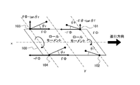
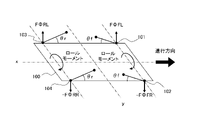
- FIG. 8 shows a method of applying a roll moment to the vehicle 100 by controlling the longitudinal force of each of the wheels 101-104 and causing the vehicle 100 to take a preliminary posture (roll posture).
- the angle of the virtual link between the front wheels 101 and 102 is ⁇ f
- the angle of the virtual link between the rear wheels 103 and 104 is ⁇ r.
- the microcomputer 410 applies a braking force ⁇ F ⁇ to the left front wheel 101, a driving force F ⁇ to the right front wheel 102, a driving force F ⁇ to the left rear wheel 103, and a braking force ⁇ F ⁇ to the right rear wheel 104. gives F ⁇ . 8 the microcomputer 410 applies the driving force F ⁇ to the left front wheel 101, the braking force ⁇ F ⁇ to the right front wheel 102, and the braking force ⁇ F ⁇ to the left rear wheel 103. , and the driving force F ⁇ is applied to the right rear wheel 104 .
- the microcomputer 410 applies the first driving force to the first wheel, which is one of the front wheels 101 and 102 of the vehicle 100, in the traveling direction of the vehicle 100, and A second driving force is applied to the second wheel, which is the other wheel of 101 and 102 , in the direction opposite to the traveling direction of vehicle 100 . Furthermore, microcomputer 410 provides a third wheel, which is a wheel on the side of the first wheel among rear wheels 103 and 104 of vehicle 100, in a direction opposite to the direction of travel of vehicle 100, to a third wheel that balances the first driving force. A driving force is applied, and a fourth driving force balanced with the second driving force is applied to the fourth wheel, which is the wheel on the side of the second wheel, among the rear wheels 103 and 104 of the vehicle 100 in the traveling direction of the vehicle 100 .
- anti-dive force Fad acts on left front wheel 101
- anti-squat force Fas acts on right front wheel 102
- An anti-dive force Fad acts on the wheel 103
- an anti-squat force Fas acts on the right rear wheel 104 . That is, the anti-dive force Fad acts on the left front and rear wheels 101 and 103 of the vehicle 100 , and the anti-squat force Fas acts on the right front and rear wheels 102 and 104 of the vehicle 100 .
- the microcomputer 410 applies longitudinal force (braking/driving force) to each of the wheels 101 to 104 as shown in FIG.
- a roll moment which is a force
- the attitude of the vehicle 100 is controlled so that the left side of the vehicle 100 is higher than the right side (in other words, a roll state).
- the microcomputer 410 can roll the vehicle 100 before entering a curve by controlling the longitudinal force of each of the wheels 101-104, and the driving force F ⁇ and the braking force corresponding to the target roll moment Mx.
- the roll angle can be controlled according to the curvature of the road and the vehicle speed.
- the front-rear force applied to the left front wheel 101 and the left rear wheel 103 by the microcomputer 410 has the same absolute value and the opposite direction.
- the front and rear forces applied to and are forces of the same absolute value and opposite directions. Therefore, the longitudinal force applied to each wheel 101-104 by the attitude control by the microcomputer 410 is balanced between the left front wheel 101 and the left rear wheel 103 and between the right front wheel 102 and the right rear wheel 104. Therefore, as shown in FIG. 8, by posture control that independently applies longitudinal forces balanced in the front and rear directions to each wheel, it is possible to apply a roll moment to the vehicle 100 without generating acceleration in the front, rear, left, and right directions. .
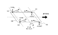
- FIG. 9 shows a method of applying a pitch moment to the vehicle 100 by controlling the longitudinal force of each of the wheels 101-104 and causing the vehicle 100 to take a preliminary posture (pitch posture).
- microcomputer 410 applies braking force ⁇ F ⁇ to front left wheel 101, braking force ⁇ F ⁇ to front right wheel 102, driving force F ⁇ to rear left wheel 103, and driving force to rear right wheel 104.
- F ⁇ the pitch moment
- the microcomputer 410 applies the first driving force to the first wheel, which is one of the front wheels 101 and 102 of the vehicle 100, in the direction opposite to the traveling direction of the vehicle 100.
- the second driving force is applied to the second wheel, which is the other wheel of the front wheels 101 and 102, in the direction opposite to the traveling direction of the vehicle 100.
- microcomputer 410 applies a third driving force, which balances the first driving force, to the third wheel, which is the wheel on the side of the first wheel among rear wheels 103 and 104 of vehicle 100, in the traveling direction of vehicle 100.
- the fourth wheel which is the wheel on the second wheel side among the rear wheels 103 and 104 of the vehicle 100, is given a fourth driving force in the traveling direction of the vehicle 100, which balances with the second driving force.
- microcomputer 410 can apply a pitch moment to cause vehicle 100 to drop forward (nose dive state) by applying a longitudinal force to wheels 101-104 as shown in FIG. That is, the microcomputer 410 can cause the vehicle 100 to take a pitch attitude before entering a curve by controlling the longitudinal force of each of the wheels 101-104, and the driving force F ⁇ and the braking force corresponding to the target pitch moment Mx.
- the pitch angle can be controlled according to the curvature of the road and the vehicle speed.
- the braking force ⁇ F ⁇ applied to the left front wheel 101 and the driving force F ⁇ applied to the left rear wheel 103 by the microcomputer 410 have the same absolute value and opposite directions.
- the braking force ⁇ F ⁇ applied to the right front wheel 102 and the driving force F ⁇ applied to the right rear wheel 104 by the microcomputer 410 have the same absolute value but opposite directions. Therefore, the longitudinal force applied by posture control by the microcomputer 410 is balanced between the left front wheel 101 and the left rear wheel 103 and between the right front wheel 102 and the right rear wheel 104 . Therefore, as shown in FIG. 9, by attitude control that independently applies front and rear balanced forces to each wheel, it is possible to apply a pitch moment to the vehicle 100 without generating front, rear, left, and right accelerations.
- the microcomputer 410 coordinates the roll moment control and the pitch moment control, in other words, the microcomputer 410 can synchronize the roll moment control and the pitch moment control.
- F FR longitudinal force F RL applied to the left rear wheel 103
- longitudinal force F RR applied to the right rear wheel 104 are set as follows.
- FIG. 10 shows that when the vehicle 100 is an FF (front engine/front drive) vehicle with front wheels 101 and 102 as driving wheels or an FR (front engine/rear drive) vehicle with rear wheels 103 and 104 as driving wheels, In other words, the attitude control of the vehicle 100 in which independent driving force cannot be applied to each of the four wheels will be described.
- FIG. 10 shows that when the vehicle 100 is an FF vehicle in which the left front wheel 101 and the right front wheel 102 are connected via a drive shaft, a roll moment is applied to the vehicle 100 by longitudinal force control, and the vehicle 100 is in a preliminary posture.
- the microcomputer 410 applies a driving force F ⁇ to the front left wheel 101 and the front right wheel 102, which are the driving wheels, and a braking force -F ⁇ to the front left wheel 101 and the rear right wheel 104, respectively.
- the microcomputer 410 controls the first wheel, which is one of the front wheels 101 and 102 of the vehicle 100, and the other wheel of the front wheels 101, 102, and the first wheel.
- a first driving force is applied in the traveling direction of the vehicle 100 to a second wheel connected to the first wheel via a drive shaft.
- microcomputer 410 provides the third wheel, which is the wheel on the side of the first wheel among rear wheels 103 and 104 of vehicle 100, with the first driving force that balances the first driving force in the direction opposite to the traveling direction of vehicle 100.
- a braking force is applied, and a second braking force balanced with the first driving force is applied to the second wheel in the direction opposite to the traveling direction of the vehicle 100 .
- an anti-squat force Fas acts on the right front wheel 102 due to the driving force F ⁇ .
- the driving force F ⁇ and the braking force ⁇ F ⁇ are simultaneously applied to the left front wheel 101, the driving force F ⁇ and the braking force ⁇ F ⁇ are balanced, and as a result, the anti-squat force Fas does not act.
- the microcomputer 410 applies the driving force F ⁇ to the right front wheel 102 to apply the anti-squat force Fas.
- a braking force -F ⁇ balanced with the driving force F ⁇ is applied to the left front wheel 101 so that Fas does not work.
- the left rear wheel 103 is not provided with the braking force -F ⁇ and the driving force F ⁇ , the anti-dive force Fad and the anti-squat force Fas do not act.
- the microcomputer 410 applies the driving force F ⁇ and the braking force ⁇ F ⁇ to the left front wheel 101, the driving force F ⁇ to the right front wheel 102, and the braking force ⁇ F ⁇ to the right rear wheel 104. In each case, the driving force F ⁇ and the braking force ⁇ F ⁇ are balanced. Therefore, the microcomputer 410 can cause the vehicle 100, which is the FF vehicle, to assume a roll posture without generating acceleration in the front, rear, left, and right directions.
- the microcomputer 410 applies the driving force F.PHI. Give power -F ⁇ . That is, when the FF vehicle is to take a roll posture, the microcomputer 410 controls the first wheel, which is one of the pair of front wheels 101 and 102 of the vehicle 100, and the other wheel of the pair of front wheels 101 and 102. It applies a first longitudinal force (driving force F ⁇ ) in the traveling direction of the vehicle 100 to the second wheel connected to the first wheel via the drive shaft. Further, the microcomputer 410 controls the third and second wheels of the pair of rear wheels 103 and 014 of the vehicle 100 on the side opposite to the traveling direction of the vehicle 100. A second longitudinal force (braking force -F ⁇ ) balanced with the first longitudinal force (driving force F ⁇ ) is applied.
- FIG. 11 shows that when the vehicle 100 is an FR vehicle in which the left rear wheel 103 and the right rear wheel 104 are connected via a drive shaft, a roll moment is applied to the vehicle 100 by controlling the longitudinal force, and the vehicle 100 A method of taking a preliminary posture (roll posture) is shown.
- the microcomputer 410 applies a driving force F ⁇ to the left rear wheel 103 and the right rear wheel 104, which are the drive wheels, and applies a braking force ⁇ F ⁇ to the left front wheel 101 and the right rear wheel 104.
- FIG. 11 shows that when the vehicle 100 is an FR vehicle in which the left rear wheel 103 and the right rear wheel 104 are connected via a drive shaft, a roll moment is applied to the vehicle 100 by controlling the longitudinal force, and the vehicle 100 A method of taking a preliminary posture (roll posture) is shown.
- the microcomputer 410 applies a driving force F ⁇ to the left rear wheel 103 and the right rear wheel 104, which are the drive wheels, and applies a braking force ⁇ F ⁇ to the
- the microcomputer 410 controls the first wheel, which is one of the rear wheels 103 and 104 of the vehicle 100, and the other wheel of the rear wheels 103 and 104, A first driving force is applied in the traveling direction of the vehicle 100 to the second wheels connected to the first wheels via a drive shaft. Furthermore, microcomputer 410 provides a first braking force that balances the first driving force in the direction opposite to the traveling direction of vehicle 100 to the third wheel, which is the wheel on the side of the first wheel, among front wheels 101 and 102 of vehicle 100 . Power is applied to the second wheel, and a second braking force balanced with the first driving force is applied to the second wheel in the direction opposite to the traveling direction of the vehicle 100 .
- an anti-dive force Fad acts on the left rear wheel 103 due to the driving force F ⁇ .
- the driving force F ⁇ and the braking force ⁇ F ⁇ are applied to the right rear wheel 104, the driving force F ⁇ and the braking force ⁇ F ⁇ are balanced, and as a result, the anti-dive force Fad does not act.
- the vehicle control device 400 applies the driving force F ⁇ to the left rear wheel 103 to apply the anti-dive force Fad.
- a braking force -F ⁇ is applied to the right rear wheel 104 so that the dive force Fad does not act.
- An anti-dive force Fad acts on the left front wheel 101 due to the braking force ⁇ F ⁇ .
- anti-dive force Fad and anti-squat force Fas do not act. 11
- the microcomputer 410 applies a longitudinal force to each wheel 101 to 104 as shown in FIG. can be controlled to a high tilt state (roll posture). Further, the microcomputer 410 applies the driving force F ⁇ and the braking force ⁇ F ⁇ to the right rear wheel 104, the braking force ⁇ F ⁇ to the left front wheel 101, and the driving force F ⁇ to the left rear wheel 103. The driving force F ⁇ and the braking force ⁇ F ⁇ are balanced on the left and right sides, respectively. Therefore, microcomputer 410 can cause vehicle 100, which is an FR vehicle, to assume a roll posture without generating acceleration in the front, rear, left, and right directions.
- the microcomputer 410 controls the first wheel, which is one of the pair of rear wheels 103 and 104 of the vehicle 100, and the other wheel of the pair of rear wheels. It applies a first longitudinal force in the traveling direction of the vehicle 100 to the second wheel connected to the first wheel via the drive shaft. Furthermore, the microcomputer 410 provides the third wheel, which is the wheel on the first wheel side of the pair of front wheels 101 and 102 of the vehicle 100, and the second wheel, on the side opposite to the traveling direction of the vehicle. A second longitudinal force is applied to balance the first longitudinal force.
- FIG. 12 shows a method of applying a pitch moment to vehicle 100 by longitudinal force control to cause vehicle 100 to take a preliminary posture (pitch posture) when vehicle 100 is an FR vehicle.
- the microcomputer 410 applies a driving force F ⁇ to the left rear wheel 102 and the right rear wheel 104, which are driving wheels, and applies a braking force ⁇ F ⁇ to the left front wheel 101 and the right front wheel 102.
- the microcomputer 410 controls the first wheel, which is one of the rear wheels 103, 104 of the vehicle 100, and the other wheel, which is the other of the rear wheels 103, 104, through the drive shaft.
- a first driving force is applied to the connected second wheels in the traveling direction of the vehicle 100 .
- the microcomputer 410 applies a first braking force that balances the first driving force to the third wheel, which is the wheel on the side of the first wheel, among the front wheels 101 and 102 of the vehicle 100 in the direction opposite to the traveling direction of the vehicle.
- Power is applied, and a second braking force balanced with the first driving force is applied to the fourth wheel, which is the wheel on the side of the second wheel among the front wheels 101 and 102 of the vehicle 100, in the direction opposite to the traveling direction of the vehicle 100.
- microcomputer 410 can apply a pitch moment to cause vehicle 100 to drop forward (nose dive state) by applying a longitudinal force to wheels 101-104 as shown in FIG.
- microcomputer 410 applies the driving force F ⁇ to the left rear wheel 103 and the right rear wheel 104, and applies the braking force ⁇ F ⁇ to the left front wheel 101 and the right front wheel 102.
- F ⁇ and the braking force ⁇ F ⁇ are balanced. Therefore, microcomputer 410 can cause vehicle 100, which is an FR vehicle, to take a pitch posture (nose dive posture) without generating longitudinal and lateral acceleration.
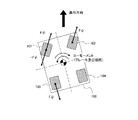
- FIG. 13 shows a method of applying a yaw moment to the vehicle 100 that can be implemented regardless of whether it is possible to apply driving force to the four wheels independently. 13 shows a case where the vehicle 100 is an FF vehicle or has in-wheel motors for each of the wheels 101-104 and can apply driving force to both front wheels 101 and 102.
- FIG. 13 shows a case where the vehicle 100 is an FF vehicle or has in-wheel motors for each of the wheels 101-104 and can apply driving force to both front wheels 101 and 102.
- microcomputer 410 applies driving force F.psi. to left front wheel 101 and right front wheel 102, while applying braking force -F.psi.
- driving force F.PSI. is applied to the front left wheel 101 and the front right wheel 102, while the braking force -F.PSI.
- the microcomputer 410 By applying a braking force to one side of the vehicle 100, the microcomputer 410 generates a yaw moment, which is a force that rotates the vehicle body about the Z-axis vertically penetrating the center of gravity of the vehicle 100.
- a yaw moment which is a force that rotates the vehicle body about the Z-axis vertically penetrating the center of gravity of the vehicle 100.
- the driving force F ⁇ is applied to the left front wheel 101 and the right front wheel 102
- the braking force -F ⁇ is applied to the left front wheel 101 and the left rear wheel 103. are balanced, and the vehicle 100 does not generate forward, backward, leftward, or rightward acceleration.
- microcomputer 410 steers the yaw moment that cancels the yaw moment generated by applying the braking force so that the traveling direction of the vehicle 100 does not change due to the yaw moment generated by applying the braking force to one side. , that is, by controlling the steering angle (in other words, the steering force).
- microcomputer 410 can cause vehicle 100 to take a yaw attitude without changing the traveling direction of vehicle 100 and without causing vehicle 100 to generate longitudinal and lateral acceleration.
- the microcomputer 410 applies the first driving force to the first wheel, which is one of the front wheels 101 and 102 of the vehicle 100, in the traveling direction of the vehicle 100, and A second driving force is applied in the traveling direction of the vehicle 100 to the second wheel, which is the other of the wheels 101 and 102 .
- the microcomputer 410 applies a first braking force to the first wheel in a direction opposite to the traveling direction of the vehicle 100 to balance the first driving force, thereby A second braking force balanced with the second driving force is applied to the third wheel, which is the wheel on the side of the vehicle 100, in the direction opposite to the traveling direction of the vehicle 100, and the first driving force, the second driving force, and the first braking force are applied.
- a steering force is applied to the vehicle 100 to generate a yaw moment in the direction of canceling the yaw moment generated in the vehicle by the power and the second braking force.
- the microcomputer 410 controls the braking/driving force, in other words, the driving force in the traveling direction of the vehicle 100 and the driving force in the direction opposite to the traveling direction of the vehicle 100, thereby controlling the roll moment and the pitch moment. , a yaw moment can be applied to the vehicle 100 from before the curve to allow the vehicle 100 to assume a preliminary posture.
- the suspension system 530 is a semi-active suspension or the like and is capable of controlling the damping force of each wheel 101-104
- the microcomputer 410 controls the vehicle control device 400 in parallel with the control of the braking/driving force. By controlling the damping force by using
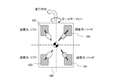
- FIG. 14 illustrates damping force control (in other words, damping command output control) that microcomputer 410 performs in parallel with roll moment control for causing vehicle 100 to take a preliminary posture.
- the microcomputer 410 controls the braking/driving force as illustrated in FIGS. to control.
- microcomputer 410 calculates the damping force of the suspension of right front wheel 102 and right rear wheel 104 (for example, the damping force of the turning outer wheel), which is the side that is lowered by the roll moment, as damping force of left front wheel 101 and left rear wheel 104. It is made larger than the damping force in the pension (for example, the damping force of the turning inner wheel). By adjusting the damping force as described above, the microcomputer 410 can suppress the roll angle increase speed due to the occurrence of the roll moment, and can suppress the attitude control from giving the occupant a sense of uneasiness and discomfort. .
- microcomputer 410 controls the damping force in the suspension of front wheels 101 and 102 to reduce the damping force in the suspension of rear wheels 103 and 104 when vehicle 100 is caused to take a nosedive posture by controlling the braking/driving force as illustrated in FIG. Make it larger than the damping force in the pension. As a result, it is possible to prevent the vehicle 100 from nose-diving suddenly, and it is possible to prevent the occupant from feeling uneasy and uncomfortable due to the attitude control.
- FIG. 15 shows an example of a damping force adjustment pattern when the roll moment control and the pitch moment control are linked.
- the microcomputer 410 controls the braking/driving force of each wheel, etc., to apply a roll moment to the vehicle body so that the left side of the vehicle 100 is tilted higher than the right side thereof, and the vehicle body is in a nose dive state. Giving a pitch moment to the car body.
- microcomputer 410 for example, as shown in FIG.
- the microcomputer 410 can simultaneously adjust the roll speed of the vehicle body due to the roll moment and the pitch speed of the vehicle body due to the pitch moment.
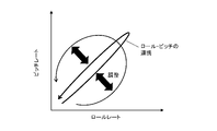
- the microcomputer 410 can also monitor the roll rate and pitch rate and adjust the damping force according to the state of the roll rate and pitch rate.
- FIG. 16 is a diagram conceptually showing the adjustment of the damping force according to the roll rate and pitch rate.
- the microcomputer 410 adjusts the damping force so as to give priority to suppressing the roll rate when the roll rate of the vehicle 100 increases. As the 100 pitch rate increases, damping force adjustments can be made to prioritize suppression of the pitch rate.
- the suspension system 530 is a suspension system such as a full active suspension, in which the displacement of the sprung mass (vehicle body) can be independently controlled by each of the wheels 101 to 104, the microcomputer 410 can control the displacement of the sprung mass of each wheel.
- the attitude of the vehicle 100 can be controlled by controlling with 101-104.
- FIG. 17 shows a state in which the microcomputer 410 applies a roll moment to the vehicle body by controlling sprung displacement (in other words, vertical force applied to the vehicle body).
- the microcomputer 410 controls the suspension system 530 to apply forces F ⁇ FL and F ⁇ RL to the left front wheel 101 and the left rear wheel 103 to raise the vehicle height. 102 and the right rear wheel 104 are exerted forces -F ⁇ FR and -F ⁇ RR in the direction of lowering the vehicle height.
- the microcomputer 410 can apply a roll moment to the vehicle body and control the left side of the vehicle 100 to be higher than the right side (in other words, roll state).
- FIG. 18 shows a state in which the microcomputer 410 applies a pitch moment to the vehicle body by controlling the displacement of the sprung mass.
- the microcomputer 410 controls the suspension device 530 to apply forces ⁇ F ⁇ FL and ⁇ F ⁇ FR in the direction of lowering the vehicle height to the front left wheel 101 and the front right wheel 102. Forces F ⁇ RL and F ⁇ RR are applied to the rear wheel 103 and the right rear wheel 104 to raise the vehicle height.
- the microcomputer 410 can apply a pitch moment to the vehicle 100 and control the vehicle 100 to a nose dive state in which the front side is lower than the rear side.
- the microcomputer 410 can coordinate roll moment control by sprung displacement and pitch moment control by sprung displacement. For example, when the roll moment control shown in FIG. 17 and the pitch moment control shown in FIG .
- the vertical force F FR applied to the front wheel 102 portion, the vertical force F RL applied to the left rear wheel 103 portion of the vehicle body, and the vertical force F RR applied to the right rear wheel portion 104 portion of the vehicle body are set as follows.
- FRL F ⁇ RL + F ⁇ RL
- F RR -F ⁇ RR +F ⁇ RR That is, when the control of the roll moment by adjusting the vertical force of each of the wheels 101-104 and the control of the pitch moment by adjusting the vertical force of each of the wheels 101-104 are linked, the microcomputer 410 controls the roll moment.
- the sum of the vertical force and the vertical force for controlling the pitch moment is defined as the vertical force for attitude control.
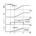
- FIG. 19 is a timing chart showing changes in the roll angle, roll rate, etc., when attitude control is performed to produce a roll angle in the direction of the roll that would occur when the vehicle 100 travels around the curve before the vehicle 100 enters the curve. Chart.
- Microcomputer 410 performs attitude control based on information such as the curvature of the road at the preview position from time t11 before steering is started (in other words, from before vehicle 100 enters a curve). to start.
- the microcomputer 410 applies the above-described braking/driving force, etc. (see FIGS. 8 and 11) to apply a roll moment that generates a lateral tilt such that the inner wheel of the turn floats and the outer wheel of the turn sinks in the preceding curve.
- generated from the front of the curve by FIG. 20 shows a state in which microcomputer 410 applies a roll moment to vehicle 100 before a curve in a direction in which the inner wheels of the vehicle 100 are lifted during curve travel.
- the microcomputer 410 gradually increases the roll angle of the vehicle 100 before entering the curve, and finally (at time t13), the roll angle changes to match the curvature of the curve and the vehicle speed.
- the microcomputer 410 starts to gradually increase the roll angle from before the vehicle 100 enters the curve toward the roll angle that will occur when the vehicle 100 enters the curve.
- a preliminary posture in front of you let them take a roll posture.
- the occupants of the vehicle 100 can recognize the entry into the curve in advance, and the occupants can be given a sense of security.
- the roll rate during cornering can be reduced, the occupants are prevented from shaking due to changes in the attitude of the vehicle 100, and the comfort of the occupants is improved.
- FIG. 21 is a time chart showing changes in the roll angle and the like when attitude control is performed to produce a roll angle in the opposite direction to the roll direction that would be caused by traveling on the curve before the vehicle 100 enters the curve.
- the microcomputer 410 performs attitude control to roll the vehicle body in the direction opposite to the roll that would occur when the vehicle 100 travels around the curve from the start of attitude control (time t21) before the vehicle 100 enters the curve.
- Attitude control to generate roll is started.
- FIG. 22 shows a state in which the microcomputer 410 applies a roll moment to the vehicle 100 before the curve in the direction opposite to the direction in which the inner wheel of the vehicle 100 floats when traveling on the curve.
- microcomputer 410 maintains the predetermined reverse roll angle until vehicle 100 actually enters the curve at time t22 (until steering is started). Then, after actually entering the curve at time t22 (in other words, after steering is started), the microcomputer 410 gradually decreases the roll angle in the reverse direction, once returns to the no-roll state, and then the inner wheel of the turn floats. , generates the original roll angle at which the turning outer ring sinks.
- the vehicle 100 assumes a roll posture before the vehicle 100 enters the curve, the occupant of the vehicle 100 can recognize the entry into the curve in advance, and the occupant can be given a sense of security.
- the roll angle in the opposite direction is generated before the vehicle 100 enters the curve, the roll angle during curve travel is reduced. operability is improved.
- FIG. 23 is a time chart showing changes in the pitch angle and the like when attitude control is performed to cause vehicle 100 to assume a nose dive attitude before vehicle 100 enters a curve.
- the microcomputer 410 performs attitude control to set the pitch angle to the nosedive state from the start of the attitude control (time t31) before the vehicle 100 enters the curve, in other words, the control to give the pitch moment that causes the nosedive. (See FIG. 9, etc.).
- FIG. 24 shows a state in which microcomputer 410 applies a pitch moment to vehicle 100 in the nose dive direction before a curve.
- microcomputer 410 After actually entering the curve at time t32 (in other words, after steering is started), microcomputer 410 maintains a predetermined pitch angle for a nose dive state.
- a nosedive posture pitch posture
- the occupant of the vehicle 100 can recognize in advance that the vehicle 100 will enter the curve, which can give the occupant a sense of security.
- FIG. 25 is a timing chart showing changes in roll angle, pitch angle, etc., when attitude control is performed to make the vehicle 100 assume a diagonal roll attitude before a curve by linking the roll moment control and the pitch moment control. Chart. Note that the diagonal roll is a state in which the turning outer wheels of the front wheels of the vehicle 100 sink and the diagonal rear wheels rise.
- Microcomputer 410 performs attitude control that links roll moment control and pitch moment control from the start of attitude control (time t41) before vehicle 100 enters a curve, and then turns during curve travel. Realize a diagonal roll posture that matches the inside and outside.
- FIG. 26 shows a state in which microcomputer 410 applies a roll moment and a pitch moment to vehicle 100 in order to cause vehicle 100 to assume a diagonal roll attitude before a curve.
- the vehicle 100 assumes the diagonal roll attitude before entering the curve, the occupants of the vehicle 100 can recognize the entry into the curve in advance, and the occupants can be given a sense of security.
- the roll rate during cornering can be reduced, the occupants are prevented from shaking due to changes in the attitude of the vehicle 100, and the comfort of the occupants is improved.
- the behavior of the vehicle 100 while traveling on a curve changes smoothly, and the occupant's sense of security and comfort are further improved.
- FIG. 27 is a time chart showing changes in the yaw rate, yaw angle, etc. when attitude control is performed to generate a yaw angle in vehicle 100 before vehicle 100 enters a curve.
- Microcomputer 410 controls to generate a yaw moment without changing the direction of travel from time t51 prior to time t52 when steering is started (in other words, from before vehicle 100 enters a curve). 13) to generate a yaw angle.
- FIG. 28 shows a state in which microcomputer 410 applies a yaw moment to vehicle 100 in order to make vehicle 100 take a yaw attitude before a curve.
- the yaw rate during curve travel can be reduced, and changes in the occupant's field of vision are moderated, reducing the burden and fatigue of the occupant.
- occupant sway is reduced and occupant comfort is improved.
- attitude control by the microcomputer 410 is summarized as follows. 1.
- the occupant can be made to recognize in advance that the vehicle will enter the curve, and the occupant can be given a sense of security. 2. It is possible to suppress the roll rate during curve travel and reduce the sway of the occupants. 3.
- the roll angle during curve travel can be suppressed, and the seated posture of the occupant can be easily maintained. 4. By suppressing the roll rate and roll angle during curve travel, passenger comfort and driver operability are improved.
- the microcomputer 410 performs control so that the front, rear, left, and right accelerations generated in the vehicle 100 do not change when performing the attitude control function described above. As a result, inertia due to longitudinal and lateral acceleration that is not intended by the occupant does not occur, and the following effects are obtained. 1. It is possible to prevent the occupant from feeling uneasy and uncomfortable. 2. Impairment of ride comfort and comfort of the occupant can be suppressed.
- the vehicle control device provides information on the curvature of the road ahead of the vehicle, information on the speed of the vehicle, information on the number of passengers in the vehicle (load weight), information on the road gradient, information on the bank angle of the road, and information on the continuity of the curve. Based on at least one of the information, the information of the coefficient of friction of the road, etc., the preliminary posture to be taken before the curve can be switched. That is, the vehicle control device can switch which of the roll moment (forward roll, reverse roll), pitch moment, and yaw moment to be generated before the curve, according to the running conditions of the vehicle 100 .
- the vehicle control device when the roll rate predicted to occur at the preview position exceeds a threshold value, the vehicle control device generates a roll moment from before the curve to roll in the roll direction due to travel on the curve, and predicts the occurrence at the preview position.
- the roll rate is less than the threshold but the roll angle is predicted to exceed the threshold, a roll moment can be generated before the curve to roll in the direction opposite to the roll direction due to curve travel.
- the vehicle control device sets the distance threshold L3 under the third start condition and/or the time threshold t4 under the fourth start condition at the preview position.
- At least one of information about the curvature Kp, information about the deviation between the curvature Kp at the preview position and the curvature Kv at the current position, and information indicating which of roll moment, pitch moment, and yaw moment is to be generated before the curve. can be changed based on
- the vehicle control device includes a control section that outputs a result of calculation based on input information
- the control unit Acquire the physical quantity related to the forward curvature of the road on which the vehicle travels, obtaining a physical quantity related to the speed of the vehicle;
- a longitudinal force is generated on the wheels of the vehicle so as to generate a moment for changing the attitude of the vehicle from before the curve of the travel path according to the physical quantity relating to the curvature of the front and the physical quantity relating to the speed.
- it outputs a control command to an actuator section that applies a vertical force to the vehicle body of the vehicle.
- control section outputs a control command to the actuator section so as to generate a roll moment that rolls the vehicle in a roll direction caused by traveling on the curve from before the curve of the travel path.
- control unit instructs the actuator unit to generate a roll moment that causes the vehicle to roll in a direction opposite to a roll direction caused by traveling on the curve before a curve on the travel path.
- control section outputs a control command to the actuator section so as to generate a pitch moment that causes the vehicle to nose-dive from before the curve of the travel path.
- control unit generates a roll moment for rolling the vehicle in a roll direction due to traveling on the curve and a pitch moment for nose-dive of the vehicle from before the curve of the travel path. , to output a control command to the actuator unit.
- control unit includes a first longitudinal force in a traveling direction of the vehicle and a first longitudinal force in a direction opposite to the traveling direction of the vehicle that balances the first longitudinal force on each of the left and right sides of the vehicle. 2 to generate a fore-and-aft force.
- control section causes the vehicle to generate a first yaw moment by varying the longitudinal force generated in each wheel of the vehicle between the left and right wheels, and cancels the first yaw moment.
- a steering angle command for generating the second yaw moment of is output to the steering device.
- control section outputs a damping force control command for adjusting the speed of the attitude change to the suspension system when changing the attitude of the vehicle before a curve.
- control section outputs a control command to the actuator section so as to generate a roll moment and a pitch moment before a curve of the travel path, and based on the roll rate and the pitch rate, Outputs a control command to adjust the damping force to the suspension system.
- SYMBOLS 100... Vehicle, 200... Vehicle control system, 300... External recognition part, 400... Vehicle control apparatus (control unit), 410... Microcomputer (control part), 500... Actuator part, 510... Driving device, 520... Braking device, 530... Suspension system, 540... Steering system
Landscapes
- Engineering & Computer Science (AREA)
- Mechanical Engineering (AREA)
- Transportation (AREA)
- Chemical & Material Sciences (AREA)
- Combustion & Propulsion (AREA)
- Automation & Control Theory (AREA)
- Physics & Mathematics (AREA)
- Mathematical Physics (AREA)
- Control Of Driving Devices And Active Controlling Of Vehicle (AREA)
Abstract
Description
しかし、従来は、車両に挙動が発生してから前後力などを制御し、挙動発生前には、挙動発生に備えた予備動作や挙動の緩和動作を実施しないので、車両がカーブを走行するときの乗員の安心感が低下するおそれがあった。
図1は、車両100に搭載される車両制御システム200の一態様を示すブロック図である。
車両制御システム200は、車両100の自動運転などの運転支援を行うシステムである。
車両制御システム200は、外界認識部300、車両制御装置400、アクチュエータ部500を備える。
外界認識部300は、ステレオカメラ310、ナビゲーション装置320、無線通信装置330などを備える。
ステレオカメラ310は、車両100の周囲を撮影して、車両100の周囲の画像情報を取得し、また、三角測量法によって対象物までの距離を測定する。
GPS受信部321は、GPS衛星から信号を受信することにより、車両100の位置の緯度及び経度を測定する。
地図データベース322は、車両100に搭載された記憶装置内に形成される。
ナビゲーション装置320は、GPS受信部321が測定した車両100の位置の情報に基づき地図データベース330を参照して、車両100が走行している道路を特定し、また、車両100の目的地までの経路を設定する。
路車間通信は、自車と走行路に設置された路側機との間の無線通信であり、車車間通信は、自車と他の車両との間の無線通信である。
また、無線通信装置330は、車車間通信において、自車に関する情報を他の車両に向けて送信し、他の車両から当該車両に関する情報を受信する。
マイクロコンピュータ410は、図示を省略したMPU(Microprocessor Unit)、ROM(Read Only Memory)、RAM(Random Access Memory)などを有する。
そして、マイクロコンピュータ410は、取得した各種情報に基づきアクチュエータ部500を作動させるための制御指令を演算し、演算した制御指令をアクチュエータ部500に出力する。
制動装置520は、たとえば、油圧のエネルギー源を備え、各車輪101-104のブレーキシリンダに供給する油圧を調整することによって、各車輪101-104に付与する制動力を個別に調整できる油圧式の制動装置である。
操舵装置540は、たとえば、前輪101,102の操舵力を発生するモータを備えた電動式の操舵装置である。
係る姿勢制御において、マイクロコンピュータ410は、車両100が走行する走行路における前方の曲率に関する物理量を取得し、また、車両100の速度に関する物理量を取得する。
つまり、マイクロコンピュータ410は、前方の曲率及び車両100の速度に基づき、車両100が所定の予備姿勢をとるための制御モーメントを求め、係る制御モーメントを発生させるように、車輪101-104毎に駆動力、制動力、或いは懸架装置530のばね上の変位を制御し、さらに減衰力或いは操舵力(操舵角)を制御する。
なお、マイクロコンピュータ410は、制御モーメントを得ながら、車両100に発生する前後左右の加速度が変わらないように、アクチュエータ部500を作動させる制御指令を設定する。
また、車両100がカーブに入る手前から車両100にロール角やヨー角を生じさせることで、車両100がカーブを走行するときのロール角、ロールレート、或いはヨーレートが低減し、乗員の快適性や運転の操作性が向上する。
マイクロコンピュータ410は、主な機能部として、状態推定部420、統合制御部430を有する。
曲率判断部421は、外界認識部300から取得したプレビュー情報に基づき、車両100の前方のプレビュー位置における走行路の曲率に関する情報を求め、求めた曲率に関する情報を出力する。
車速制御部431は、外界認識部300から取得した車速指令、加速度指令に基づきアクチュエータ部500を制御して、車両100の車速、加速度を制御し、また、車速に関する情報を姿勢制御部432に出力する。
なお、姿勢制御部432は、車速センサ或いは車輪速センサから車速に関する情報を取得することができる。
制御指令算出部432Aは、車速制御部431から車速に関する情報を取得し、また、曲率判断部421から、車両100の前方のプレビュー位置における走行路の曲率に関する情報を取得する。
そして、制御指令算出部432Aは、取得した車速に関する情報及び走行路の曲率に関する情報に基づき、カーブ手前から車両100に発生させる、ロールモーメント、ピッチモーメント、及びヨーモーメントのうち少なくとも1つを含む制御モーメント(換言すれば、モーメント指令値)を求める。
つまり、分配制御部432Bは、制御モーメントを発生させるために、駆動装置510に駆動力指令を出力し、制動装置520に制動力指令を出力し、懸架装置530に減衰力指令を出力し、操舵装置540に操舵角指令を出力する。
マイクロコンピュータ410は、図2に示すルーチンを、たとえば時間割り込みで周期的に実行する。
次いで、マイクロコンピュータ410は、ステップS802で、ステップS801において取得した路面情報に基づき、プレビュー位置での走行路の曲率を求める。
本願では、車両100の現在位置から、車両100の前方の走行路上のプレビュー位置までの距離である距離[m]をLとし、また、車両100が現在位置から現在の車速V[km/h]でプレビュー位置に到達するのに要する時間[sec]をtとする。
また、本願では、車両100の現在位置での走行路の曲率をKvとする。
なお、車両100の重心を前後に貫くX軸を中心に車体を回転させる力がロールモーメントであり、車両100の重心を左右に貫くY軸を中心に車体を回転させる力がピッチモーメントであり、車両の重心を上下に貫くZ軸を中心に車体を回転させる力がヨーモーメントである。
図4は、曲率判断部421が、ステレオカメラ310の画像から認識された白線の情報に基づき、曲率Kpの情報を取得する方法を示す。
図5は、曲率判断部421が、ナビゲーション装置320による車両100の位置測定の結果と地図情報とに基づき地図上での自車位置を認識することで、地図情報に含まれる道路曲率の情報を検索して、曲率Kpの情報を取得する方法を示す。
図6は、曲率判断部421が、無線通信装置330を用いた路車間通信或いは車車間通信によって、路側機710や他の車両720から曲率Kpの情報を取得する方法を示す。
マイクロコンピュータ410は、ステップS803で、下記の第1開始条件と第2開始条件との少なくとも一方が成立しているか否かを判断する。
・第2開始条件:プレビュー位置での曲率Kpと現在位置での曲率Kvとの偏差が第2閾値Kp2以上である(Kp-Kv≧Kp2)
なお、第1閾値Kp1は、Kp1>0を満たし、第2閾値Kp2は、Kp2>0を満たす値である。
・第3開始条件:現在位置からプレビュー位置までの距離Lが第3閾値L3以下である(L≦L3)
・第4開始条件:車両100がプレビュー位置に到達するのに要する時間tが第4閾値t4以下である(t≦t4)
・第5開始条件:操舵角が所定角度内であり操舵開始前と推定される状態である
・第6開始条件:実ヨーレートが所定範囲内であり操舵開始前と推定される状態である
換言すれば、マイクロコンピュータ410は、車両100の前方の走行路にカーブが存在し、当該カーブの手前の所定範囲内を車両100が略直進している状態であるときに、姿勢制御を実施する。
一方、マイクロコンピュータ410は、姿勢制御の開始条件が成立していない場合、プロセスを終了させることで、姿勢制御を実施しない。
マイクロコンピュータ410は、ステップS804で、プレビュー位置での曲率Kp及び現在の車速Vに基づき、姿勢制御のための車両100の3軸まわりの目標モーメント、詳細には、目標ロールモーメントMx、目標ピッチモーメントMy、及び目標ヨーモーメントMzのうちの少なくとも1つを算出する(図3参照)。
・目標ロールモーメントMx=Cx・V・(Kp-Kv)
・目標ピッチモーメントMy=Cy・V・(Kp-Kv)
・目標ヨーモーメントMz=Cz・V・(Kp-Kv)
制御ゲインCx,Cy,Czは、車両制御システム200の設計開発段階において実験やシミュレーションなどに基づき適合され、マイクロコンピュータ410のメモリに制御定数として記憶される。
したがって、制御モーメントは、プレビュー位置での曲率Kpと現在位置での曲率Kvとの差が大きいほど大きな値になり、また、車速Vが高いほど大きな値になる。
したがって、マイクロコンピュータ410が、たとえば、車両100に予備姿勢としてのロール姿勢をとらせるためにロールモーメントMxを算出する場合、曲率Kpと車速Vとに応じて、ロールモーメントMxは車両100がカーブに近づくほど増加し、車両100のロール角は漸増することになる。

なお、数式2において、符号上部のドット記号は微分値であることを示す。

そして、マイクロコンピュータ410は、ステップS805で求めた駆動力指令(駆動指令)をステップS806で駆動装置510に出力し、ステップS805で求めた制動力指令(制動指令)をステップS807で制動装置520に出力し、ステップS805で求めた操舵角指令をステップS808で操舵装置540に出力する。
図7は、制動力F(換言すれば、車両100の進行方向とは逆方向の駆動力若しくは車両100の進行方向とは逆方向の前後力)を前輪に与えることで、前輪にアンチダイブ(anti-dive)力が働くことを説明するための図である。
なお、図7の左手が車両100の前方で、前輪の瞬間回転中心は、前輪よりも車両後方になる。
そして、制動力Fが与えられた前輪には、圧縮力F/cosθの分力として、車体を持ち上げる方向のアンチダイブ力Fad(Fad=F・tanθ)が働く。
また、後輪の場合は、瞬間回転中心が後輪よりも車両前方となるために、前輪の場合とは逆に、制動力を与えた場合に車体にアンチスクアット力Fasが働き、駆動力を与えた場合に車体にアンチダイブ力Fadが働くことになる。
そして、車両制御装置400は、車輪別の前後力制御によって制御モーメントに応じたモーメントを車体に与え、車両100に予備姿勢をとらせることができる。
図8及び図9は、駆動装置510が、車輪101-104にそれぞれ設けたインホイールモータなどであって車輪101-104毎に独立した駆動力調整が可能で、かつ、制動装置520が、車輪101-104毎に独立した制動力調整が可能である車両100での姿勢制御を示す。
なお、図8において、前輪101,102における仮想リンクの角度をθfとし、後輪103,104における仮想リンクの角度をθrとする。
なお、ロール方向を図8とは逆にする場合、マイクロコンピュータ410は、左前輪101に駆動力FΦを与え、右前輪102に制動力-FΦを与え、左後輪103に制動力-FΦを与え、右後輪104に駆動力FΦを与える。
さらに、マイクロコンピュータ410は、車両100の後輪103,104のうち前記第1車輪の側の輪である第3車輪に、車両100の進行方向と逆側に前記第1駆動力と釣り合う第3駆動力を与え、車両100の後輪103,104のうち前記第2車輪の側の輪である第4車輪に、車両100の進行方向に前記第2駆動力と釣り合う第4駆動力を与える。
つまり、車両100の左側の前後輪101,103にはアンチダイブ力Fadが働き、車両100の右側の前後輪102,104にはアンチスクアット力Fasが働く。
つまり、マイクロコンピュータ410は、車輪101-104毎の前後力の制御によって車両100がカーブに入る前からロール姿勢をとらせることができ、かつ、目標ロールモーメントMxに応じた駆動力FΦ及び制動力-FΦの設定によって、ロール角を、走行路の曲率及び車速に応じた角度に制御できる。
このため、マイクロコンピュータ410による姿勢制御によって各車輪101-104に与えられる前後力が、左前輪101と左後輪103との間、及び、右前輪102と右後輪104との間で釣り合う。
したがって、図8に示したように、前後で釣り合う前後力を各車輪に独立して与える姿勢制御によれば、車両100に前後左右の加速度を発生させることなくロールモーメントを与えることが可能である。
図9の場合、マイクロコンピュータ410は、左前輪101に制動力-Fθを与え、右前輪102に制動力-Fθを与え、左後輪103に駆動力Fθを与え、右後輪104に駆動力Fθを与える。
さらに、マイクロコンピュータ410は、車両100の後輪103,104のうち前記第1車輪の側の輪である第3車輪に、車両100の進行方向に前記第1駆動力と釣り合う第3駆動力を与え、車両100の後輪103,104のうち前記第2車輪の側の輪である第4車輪に、車両100の進行方向に前記第2駆動力と釣り合う第4駆動力を与える。
ここで、前後輪における仮想リンク角度θf,θrの違いによって、左前輪101及び右前輪102に働くアンチダイブ力Fadと、左後輪103及び右後輪104に働くアンチダイブ力Fadとに差が生じることで、車両100の重心を左右に貫くY軸を中心に車体を回転させる力であるピッチモーメントが発生する。
このため、マイクロコンピュータ410は、図9に示すように各車輪101-104に前後力を与えることで、車両100が前下がり(ノーズダイブ状態)になるピッチモーメントを与えることができる。
つまり、マイクロコンピュータ410は、車輪101-104毎の前後力の制御によって車両100がカーブに入る前からピッチ姿勢をとらせることができ、かつ、目標ピッチモーメントMxに応じた駆動力Fθ及び制動力-Fθの設定によって、ピッチ角を、走行路の曲率及び車速に応じた角度に制御できる。
このため、マイクロコンピュータ410による姿勢制御によって与えられる前後力が、左前輪101と左後輪103との間、及び、右前輪102と右後輪104との間で釣り合う。
したがって、図9に示したように、前後で釣り合う力を各車輪に独立して与える姿勢制御によれば、車両100に前後左右の加速度を発生させることなくピッチモーメントを与えることが可能である。
マイクロコンピュータ410は、たとえば、図8に示したロールモーメントの制御と、図9に示したピッチモーメントの制御とを連係させる場合、左前輪101に与える前後力FFL、右前輪102に与える前後力FFR、左後輪103に与える前後力FRL、右後輪104に与える前後力FRRを以下のように設定する。
FFR=FΦ-Fθ
FRL=FΦ+Fθ
FRR=-FΦ+Fθ
つまり、マイクロコンピュータ410は、ロールモーメントの制御とピッチモーメントの制御とを連係させる場合、車輪毎に、目標ロールモーメントMxを得るための前後力と、目標ピッチモーメントMyを得るための前後力との合計を姿勢制御のために与える前後力とする。
図10は、車両100が、左前輪101と右前輪102とが駆動軸を介して接続されるFF車両である場合に、前後力の制御によって車両100にロールモーメントを与え、車両100に予備姿勢(ロール姿勢)をとらせる方法を示す。
ここで、マイクロコンピュータ410は、駆動輪である左前輪101及び右前輪102に駆動力FΦを与える一方、左前輪101及び右後輪104に制動力-FΦを与える。
さらに、マイクロコンピュータ410は、車両100の後輪103,104のうち前記第1車輪の側の輪である第3車輪に、車両100の進行方向と逆側に前記第1駆動力と釣り合う第1制動力を与え、前記第2車輪に、車両100の進行方向と逆側に前記第1駆動力と釣り合う第2制動力を与える。
一方、左前輪101には、駆動力FΦと制動力-FΦとが同時に与えられることから、駆動力FΦと制動力-FΦとが釣り合って、結果として、アンチスクアット力Fasは働かない。
換言すれば、マイクロコンピュータ410は、右前輪102にアンチスクアット力Fasを働かせるために駆動力FΦを与えるが、このとき左前輪101にも与えられる駆動力FΦによって左前輪101にアンチスクアット力Fasが働くことがないように、左前輪101に駆動力FΦに釣り合う制動力-FΦを与える。
一方、左後輪103には、制動力-FΦ及び駆動力FΦが与えられないため、アンチダイブ力Fad及びアンチスクアット力Fasは働かない。
したがって、マイクロコンピュータ410は、車両100がFF車両である場合に、図10に示したように各車輪101-104に前後力を与えることで車両100にロールモーメントを与え、車両100に、右側よりも左側が高いロール姿勢をとらせることができる。
したがって、マイクロコンピュータ410は、FF車両である車両100に前後左右の加速度を発生させることなく、ロール姿勢をとらせることができる。
つまり、マイクロコンピュータ410は、FF車両にロール姿勢をとらせる場合、車両100の一対の前輪101,102のうち一方の車輪である第1車輪と、一対の前輪101,102のうち他方の車輪であり、前記第1車輪に駆動軸を介して接続される第2車輪に、車両100の進行方向に第1前後力(駆動力FΦ)を与える。
さらに、マイクロコンピュータ410は、車両100の一対の後輪103,014のうち前記第1車輪の側の車輪である第3車輪と、前記第2車輪に、車両100の進行方向と逆側に前記第1前後力(駆動力FΦ)と釣り合う第2前後力(制動力-FΦ)を与える。
ここで、マイクロコンピュータ410は、駆動輪である左後輪103及び右後輪104に駆動力FΦを与える一方、左前輪101及び右後輪104に制動力-FΦを与える。
さらに、マイクロコンピュータ410は、車両100の前輪101,102のうち前記第1車輪の側の輪である第3車輪に、車両100の進行方向と逆側に前記第1駆動力と釣り合う第1制動力を与え、前記第2車輪に、車両100の進行方向と逆側に前記第1駆動力と釣り合う第2制動力を与える。
一方、右後輪104には、駆動力FΦと制動力-FΦとが与えられることから、駆動力FΦと制動力-FΦとが釣り合い、結果として、アンチダイブ力Fadは働かない。
換言すれば、車両制御装置400は、左後輪103にアンチダイブ力Fadを働かせるために駆動力FΦを与えるが、このとき右後輪104にも与えられる駆動力FΦによって右後輪104にアンチダイブ力Fadが働くことがないように、右後輪104に制動力-FΦを与える。
一方、右前輪102には、制動力及び駆動力が与えられないため、アンチダイブ力Fad及びアンチスクアット力Fasは働かない。
つまり、図11に示した制駆動状態では、右前輪102及び右後輪104には、アンチダイブ力Fad及びアンチスクアット力Fasは働かないが、左前輪101にはアンチダイブ力Fad(Fad=FΦ・tanθf)が働き、左後輪103にもアンチダイブ力Fad(Fad=FΦ・tanθr)が働く。
また、マイクロコンピュータ410は、右後輪104に駆動力FΦと制動力-FΦとを与え、左前輪101に制動力-FΦを与え、左後輪103に駆動力FΦを与えるから、車両100の左右それぞれで、駆動力FΦと制動力-FΦとが釣り合う。
したがって、マイクロコンピュータ410は、FR車両である車両100に前後左右の加速度を発生させることなく、ロール姿勢をとらせることができる。
つまり、マイクロコンピュータ410は、FR車両にロール姿勢をとらせる場合、車両100の一対の後輪103,104のうち一方の車輪である第1車輪と、前記一対の後輪のうち他方の車輪であり、前記第1車輪に駆動軸を介して接続される第2車輪に、車両100の進行方向に第1前後力を与える。
さらに、マイクロコンピュータ410は、車両100の一対の前輪101,102のうち前記第1車輪の側の車輪である第3車輪と、前記第2車輪に、前記車両の進行方向と逆側に前記第1前後力と釣り合う第2前後力を与える。
ここで、マイクロコンピュータ410は、駆動輪である左後輪102及び右後輪104に駆動力Fθを与える一方、左前輪101及び右前輪102に制動力-Fθを与える。
さらに、マイクロコンピュータ410は、車両100の前輪101,102のうち前記第1車輪の側の輪である第3車輪に、前記車両の進行方向と逆側に前記第1駆動力と釣り合う第1制動力を与え、車両100の前輪101,102のうち前記第2車輪の側の輪である第4車輪に、車両100の進行方向と逆側に前記第1駆動力と釣り合う第2制動力を与える。
一方、左前輪101及び右前輪102には、制動力-Fθによってアンチダイブ力Fad(Fad=Fθ・tanθf)が働く。
このため、マイクロコンピュータ410は、図12に示すように各車輪101-104に前後力を与えることで、車両100が前下がり(ノーズダイブ状態)になるピッチモーメントを与えることができる。
したがって、マイクロコンピュータ410は、FR車両である車両100に前後左右の加速度を発生させることなく、ピッチ姿勢(ノーズダイブ姿勢)をとらせることができる。
なお、図13は、車両100が、FF車両、若しくは、各車輪101-104にインホイールモータを備え、両前輪101,102に駆動力を付与することが可能である場合を示す。
なお、図13と逆方向にヨー角を発生させる場合、左前輪101及び右前輪102に駆動力FΨを付与する一方、右前輪102及び右後輪104に制動力-FΨを与える。
また、左前輪101及び右前輪102に駆動力FΨが付与され、かつ、左前輪101及び左後輪103に制動力-FΨを付与するから、車両100の全体では、駆動力FΨと制動力とが釣り合い、車両100に前後左右の加速度は発生しない。
ここで、マイクロコンピュータ410は、片側への制動力の付与によって発生させたヨーモーメントによって車両100の進行方向が変わることがないように、制動力の付与によって発生するヨーモーメントを打ち消すヨーモーメントを操舵、つまり、操舵角(換言すれば、操舵力)の制御によって与える。
これにより、マイクロコンピュータ410は、車両100の進行方向を変えず、かつ、車両100に前後左右の加速度を発生させることなく、車両100にヨー姿勢をとらせることができる。
さらに、マイクロコンピュータ410は、前記第1車輪に、車両100の進行方向と逆側に前記第1駆動力と釣り合う第1制動力を与え、車両100の後輪103,104のうち前記第1車輪の側の輪である第3車輪に、車両100の進行方向と逆側に前記第2駆動力と釣り合う第2制動力を与え、前記第1駆動力、前記第2駆動力、前記第1制動力、及び前記第2制動力によって前記車両に発生するヨーモーメントを打ち消す方向のヨーモーメントを車両100に発生させる操舵力を与える。
ここで、懸架装置530が、セミアクティブサスペンションなどであって、各車輪101-104の減衰力の制御が可能である場合、マイクロコンピュータ410は、車両制御装置400は、制駆動力の制御に並行して減衰力を制御することで、車体の回転運動(ロール、ピッチ、ヨー)の変化速度を調整することができる。
図14に示す姿勢制御において、マイクロコンピュータ410は、図8、図10、図11に例示したような制駆動力の制御によって、車両100の右側よりも左側が高い傾斜状態となるようなロールモーメントに制御する。
マイクロコンピュータ410は、上記のように減衰力を調整することで、ロールモーメントの発生に伴うロール角の増加速度を抑止し、姿勢制御が乗員に不安感、違和感を与えることを抑止することができる。
これにより、車両100が急にノーズダイブすることを抑止でき、姿勢制御が乗員に不安感、違和感を与えることを抑止することができる。
図15は、ロールモーメントの制御とピッチモーメントの制御とを連係させるときの減衰力の調整パターンの一例を示す。
このとき、マイクロコンピュータ410は、たとえば、図15に示すように、左前輪101及び右後輪104のサスペンションの減衰力を、右前輪102及び左後輪103のサスペンションの減衰力よりも大きくする。
係る減衰力調整により、マイクロコンピュータ410は、ロールモーメントによる車体のロール速度、及び、ピッチモーメントによる車体のピッチ速度を同時に調整することができる。
図16は、ロールレート及びピッチレートに応じた減衰力の調整を、概念的に示す図である。
マイクロコンピュータ410は、ロールモーメントの制御とピッチモーメントの制御とを連係させるときに、車両100のロールレートが速くなると、ロールレートの抑制を優先させるように減衰力の調整を行い、逆に、車両100のピッチレートが速くなると、ピッチレートの抑制を優先させるように減衰力の調整を行うことができる。
図17は、マイクロコンピュータ410が、ばね上の変位(換言すれば、車体に付与する上下力)の制御によって車体にロールモーメントを与える状態を示す。
マイクロコンピュータ410は、係る懸架装置530の制御によって、車体にロールモーメントを与え、車両100の右側よりも左側が高い傾斜状態(換言すれば、ロール状態)に制御することができる。
図18に示す姿勢制御の場合、マイクロコンピュータ410は、懸架装置530を制御することで、左前輪101及び右前輪102については車高を下げる方向の力-FθFL、-FθFRを働かせ、左後輪103及び右後輪104については車高を上げる方向の力FθRL、FθRRを働かせる。
マイクロコンピュータ410は、係る懸架装置530の制御によって、車両100にピッチモーメントを与え、車両100の前側が後側よりも低いノーズダイブ状態に制御することができる。
マイクロコンピュータ410は、たとえば、図17に示したロールモーメントの制御と、図18に示したピッチモーメントの制御とを連係させる場合、車体の左前輪101の部分に与える上下力FFL、車体の右前輪102の部分に与える上下力FFR、車体の左後輪103の部分に与える上下力FRL、車体の右後輪104の部分に与える上下力FRRを以下のように設定する。
FFR=-FΦFR-FθFR
FRL=FΦRL+FθRL
FRR=-FΦRR+FθRR
つまり、車輪101-104毎の上下力調整によるロールモーメントの制御と、車輪101-104毎の上下力調整によるピッチモーメントの制御とを連係させる場合、マイクロコンピュータ410は、ロールモーメントを制御するための上下力と、ピッチモーメントを制御するための上下力との合計を、姿勢制御のための上下力とする。
図19は、車両100がカーブに入る手前から、カーブ走行によって発生するであろうロール方向に向けてロール角を生じさせる姿勢制御が実施されるときのロール角、ロールレートなどの変化を示すタイムチャートである。
マイクロコンピュータ410は、操舵が開始される時刻t12よりも前の時刻t11の時点から(換言すれば、車両100がカーブに入る手前から)、プレビュー位置における走行路の曲率の情報などに基づき姿勢制御を開始する。
図20は、マイクロコンピュータ410が、カーブ手前で、車両100にカーブ走行における旋回内輪が浮く方向にロールモーメントを与えた状態を示す。
係る姿勢制御により、マイクロコンピュータ410は、カーブに入る手前から車両100のロール角を漸増させ、最終的には(時刻t13の時点では)、当該カーブの曲率と車速に見合ったロール角にまで変化させる。
車両100がカーブに入る手前でロール姿勢をとることで、車両100の乗員はカーブ進入を事前認識することができるため、乗員に安心感を与えることができる。
また、カ-ブ走行中のロールレートを小さくできるので、乗員が車両100の姿勢変化にともなって動揺することが抑止され、乗員の快適性が向上する。
マイクロコンピュータ410は、車両100がカーブに入る手前の姿勢制御の開始時点(時刻t21)から、カーブ走行によって発生するであろうロールとは逆方向に車体をロールさせる姿勢制御、換言すれば、逆ロールを発生させる姿勢制御を開始する。
図22は、マイクロコンピュータ410が、カーブ手前で、車両100にカーブ走行の旋回内輪が浮く方向とは逆方向にロールモーメントを与えた状態を示す。
そして、マイクロコンピュータ410は、時刻t22で実際にカーブに進入した後に(換言すれば、操舵開始後に)、逆方向のロール角を漸減させ、一旦ロール無しの状態に戻してから、旋回内輪が浮き、旋回外輪が沈む本来のロール角を発生させる。
また、車両100がカーブに入る手前で逆方向のロール角を発生させることでカーブ走行中のロール角が減るため、カーブ走行中に乗員が着座姿勢を維持し易くなり、乗員の快適性や運転の操作性が向上する。
マイクロコンピュータ410は、車両100がカーブに入る手前の姿勢制御の開始時点(時刻t31)から、ノーズダイブ状態となるピッチ角にする姿勢制御、換言すれば、ノーズダイブを生じさせるピッチモーメントを与える制御(図9など参照)を実施する。
図24は、マイクロコンピュータ410が、カーブ手前で車両100にノーズダイブ方向にピッチモーメントを与えた状態を示す。
このように、カーブに入る手前において、車両100がノーズダイブ姿勢(ピッチ姿勢)をとれば、車両100の乗員はカーブ進入を事前認識できるため、乗員に安心感を与えることができる。
なお、ダイアゴナルロールは、車両100の前輪のうちの旋回外輪が沈み込み、対角の後輪が上がった状態である。
図26は、マイクロコンピュータ410が、カーブ手前で車両100にダイアゴナルロール姿勢をとらせるために、車両100にロールモーメント及びピッチモーメントを与えた状態を示す。
また、カ-ブ走行中のロールレートを小さくできるので、乗員が車両100の姿勢変化にともなって動揺することが抑止され、乗員の快適性が向上する。
さらに、ダイアゴナルロール姿勢をとることで、カーブ走行中の車両100の挙動変化が滑らかになり、乗員の安心感や快適性がより向上する。
マイクロコンピュータ410は、操舵が開始される時刻t52よりも前の時刻t51の時点から(換言すれば、車両100がカーブに入る手前から)、進行方向を変えずにヨーモーメントを発生させる制御(図13参照)を実施し、ヨー角を発生させる。
図28は、マイクロコンピュータ410が、カーブ手前で車両100にヨー姿勢をとらせるために、車両100にヨーモーメントを与えた状態を示す。
さらに、乗員の動揺が低減され、乗員の快適性が向上する。
1.乗員にカーブに進入することを予め認識させることができ、乗員に安心感を与えることができる。
2.カーブ走行中のロールレイトを抑えることができ、乗員の動揺を低減できる。
3.カーブ走行中のロール角を抑えることができ、乗員の着座姿勢が維持し易くなる。
4.カーブ走行中のロールレイト及びロール角が抑えられることで、乗員の快適性、運転者の操作性が向上する。
これにより、乗員が意図しない前後左右の加速度による慣性が発生しないため、以下のような作用効果が得られる。
1.乗員に不安感や違和感を与えることを抑止できる。
2.乗員の乗り心地や快適性が損なわれることを抑止できる。
また、好ましい実施形態を参照して本発明の内容を具体的に説明したが、本発明の基本的技術思想及び教示に基づいて、当業者であれば、種々の変形態様を採り得ることは自明である。
つまり、車両制御装置は、カーブ手前でロールモーメント(順方向のロール、逆方向のロール)、ピッチモーメント、ヨーモーメントのいずれを発生させるかを、車両100の走行条件に応じて切り換えることができる。
たとえば、車両制御装置は、プレビュー位置での発生が予測されるロールレートが閾値を超えるときに、カーブ手前からカーブ走行によるロール方向にロールさせるロールモーメントを発生させ、プレビュー位置での発生が予測されるロールレートが閾値以下であるがロール角が閾値を超えると予測されるときに、カーブ手前でカーブ走行によるロール方向とは逆方向にロールさせるロールモーメントを発生させることができる。
車両制御装置は、その一態様において、入力した情報に基づいて演算した結果を出力するコントロール部を備える車両制御装置であって、
前記コントロール部は、
車両が走行する走行路における前方の曲率に関する物理量を取得し、
前記車両の速度に関する物理量を取得し、
前記前方の曲率に関する物理量と前記速度に関する物理量とに応じて、前記走行路のカーブの手前から前記車両の姿勢を変化させるためのモーメントを生じさせるように、前記車両の車輪に前後力を発生させまたは前記車両の車体に上下力を付与するアクチュエータ部に制御指令を出力する。
別の好ましい態様では、前記コントロール部は、前記走行路のカーブの手前で前記カーブの走行によるロール方向とは逆方向に前記車両をロールさせるロールモーメントを生じさせるように、前記アクチュエータ部に制御指令を出力する。
さらに別の好ましい態様では、前記コントロール部は、前記走行路のカーブの手前から、前記カーブの走行によるロール方向に前記車両をロールさせるロールモーメント及び前記車両をノーズダイブさせるピッチモーメントを発生させるように、前記アクチュエータ部に制御指令を出力する。
さらに別の好ましい態様では、前記コントロール部は、前記車両の各車輪に発生させる前後力を左右輪で異ならせて前記車両に第1ヨーモーメントを発生させ、かつ、前記第1ヨーモーメントを打ち消す方向の第2ヨーモーメントを発生させるための操舵角指令を操舵装置に出力する。
さらに別の好ましい態様では、前記コントロール部は、前記走行路のカーブの手前で、ロールモーメント及びピッチモーメントを生じさせるように前記アクチュエータ部に制御指令を出力し、かつ、ロールレート及びピッチレートに基づき減衰力を調整する制御指令を懸架装置に出力する。
Claims (15)
- 入力した情報に基づいて演算した結果を出力するコントロール部を備える車両制御装置であって、
前記コントロール部は、
前記車両が走行する走行路における前方の曲率に関する物理量を取得し、
前記車両の速度に関する物理量を取得し、
前記前方の曲率に関する物理量と、前記速度に関する物理量と、に基づいて、前記走行路のカーブ手前から前記車両に発生させる、ロールモーメント、ピッチモーメント、及びヨーモーメントのうち少なくとも一つを含む制御モーメントを得るために前記車両に搭載されたアクチュエータ部を作動させるための制御指令を出力する、
車両制御装置。 - 請求項1に記載の車両制御装置であって、
前記コントロール部は、
前記車両に発生する前後左右の加速度が変わらないように、前記制御指令を出力する、
車両制御装置。 - 請求項1に記載の車両制御装置であって、
前記コントロール部は、
前記前方の曲率に関する物理量が所定の第1閾値以上、または前記前方の曲率に関する物理量と前記車両の現在位置の曲率に関する物理量の差が所定の第2閾値以上になる第1条件を満足し、
前記走行路における前方に対応するプレビュー位置と前記車両の現在位置との間の距離が、所定の第3閾値以下、または前記距離と前記車両の速度に関する物理量とに基づいて求められる、前記プレビュー位置までの推定到達時間が、所定の第4閾値以下になる第2条件を満足するとき、
前記制御指令を出力する、
車両制御装置。 - 請求項1に記載の車両制御装置であって、
前記アクチュエータ部は、操舵装置を含み、
前記コントロール部は、
前記前方の曲率に関する物理量が所定の第1閾値以上、または前記前方の曲率に関する物理量と前記車両の現在位置の曲率に関する物理量の差が所定の第2閾値以上になる第1条件を満足し、
前記操舵装置における操舵角が所定角度内、または取得された前記車両の実ヨーレートが所定範囲内である第3条件を満足するとき、
前記制御指令を出力する、
車両制御装置。 - 請求項1に記載の車両制御装置であって、
前記制御モーメントは、
前記前方の曲率に関する物理量と前記車両の現在位置の曲率に関する物理量の差と、前記速度に関する物理量と、に制御ゲインを乗じて求められる、
または前記前方の曲率に関する物理量と前記速度に関する物理量に基づいて求められる、前記走行路における前方に対応するプレビュー位置で前記車両に発生する推定横加速度、あるいは推定横加加速度、あるいは推定モーメントに基づいて求められる、
車両制御装置。 - 請求項1に記載の車両制御装置であって、
前記コントロール部は、
前記車両の前輪のうち一方の輪である第1車輪に、前記車両の進行方向に第1駆動力を与え、
前記前輪のうち他方の輪である第2車輪に、前記車両の進行方向と逆側に第2駆動力を与え、
前記車両の後輪のうち前記第1車輪の側の輪である第3車輪に、前記車両の進行方向と逆側に前記第1駆動力と釣り合う第3駆動力を与え、
前記車両の後輪のうち前記第2車輪の側の輪である第4車輪に、前記車両の進行方向に前記第2駆動力と釣り合う第4駆動力を与える、
ための前記制御指令を出力する、
車両制御装置。 - 請求項1に記載の車両制御装置であって、
前記コントロール部は、
前記車両の前輪のうち一方の輪である第1車輪に、前記車両の進行方向と逆側に第1駆動力を与え、
前記前輪のうち他方の輪である第2車輪に、前記車両の進行方向と逆側に第2駆動力を与え、
前記車両の後輪のうち前記第1車輪の側の輪である第3車輪に、前記車両の進行方向に前記第1駆動力と釣り合う第3駆動力を与え、
前記車両の後輪のうち前記第2車輪の側の輪である第4車輪に、前記車両の進行方向に前記第2駆動力と釣り合う第4駆動力を与える、
ための前記制御指令を出力する、
車両制御装置。 - 請求項1に記載の車両制御装置であって、
前記コントロール部は、
前記車両の前輪のうち一方の輪である第1車輪と、前記前輪のうち他方の輪であり、前記第1車輪に駆動軸を介して接続される第2車輪に、前記車両の進行方向に第1駆動力を与え、
前記車両の後輪のうち前記第1車輪の側の輪である第3車輪に、前記車両の進行方向と逆側に前記第1駆動力と釣り合う第1制動力を与え、
前記第2車輪に、前記車両の進行方向と逆側に前記第1駆動力と釣り合う第2制動力を与える、
ための前記制御指令を出力する、
車両制御装置。 - 請求項1に記載の車両制御装置であって、
前記コントロール部は、
前記車両の後輪のうち一方の輪である第1車輪と、前記後輪のうち他方の輪であり、前記第1車輪に駆動軸を介して接続される第2車輪に、前記車両の進行方向に第1駆動力を与え、
前記車両の前輪のうち前記第1車輪の側の輪である第3車輪に、前記車両の進行方向と逆側に前記第1駆動力と釣り合う第1制動力を与え、
前記第2車輪に、前記車両の進行方向と逆側に前記第1駆動力と釣り合う第2制動力を与える、
ための前記制御指令を出力する、
車両制御装置。 - 請求項1に記載の車両制御装置であって、
前記コントロール部は、
前記車両の後輪のうち一方の輪である第1車輪と、前記後輪のうち他方の輪であり、前記第1車輪に駆動軸を介して接続される第2車輪に、前記車両の進行方向に第1駆動力を与え、
前記車両の前輪のうち前記第1車輪の側の輪である第3車輪に、前記車両の進行方向と逆側に前記第1駆動力と釣り合う第1制動力を与え、
前記車両の前輪のうち前記第2車輪の側の輪である第4車輪に、前記車両の進行方向と逆側に前記第1駆動力と釣り合う第2制動力を与える、
ための前記制御指令を出力する、
車両制御装置。 - 請求項1に記載の車両制御装置であって、
前記コントロール部は、
前記車両の前輪のうち一方の輪である第1車輪に、前記車両の進行方向に第1駆動力を与え、
前記前輪のうち他方の輪である第2車輪に、前記車両の進行方向に第2駆動力を与え、
前記第1車輪に、前記車両の進行方向と逆側に前記第1駆動力と釣り合う第1制動力を与え、
前記車両の後輪のうち前記第1車輪の側の輪である第3車輪に、前記車両の進行方向と逆側に前記第2駆動力と釣り合う第2制動力を与え、
前記第1駆動力、前記第2駆動力、前記第1制動力、及び前記第2制動力によって前記車両に発生するヨーモーメントを打ち消す方向のヨーモーメントを前記車両に発生させる操舵力を与える、
ための前記制御指令を出力する、
車両制御装置。 - 請求項1に記載の車両制御装置であって、
前記制御指令は、駆動指令及び制動指令に加えて減衰指令を含む、
車両制御装置。 - 請求項1に記載の車両制御装置であって、
前記アクチュエータ部は、懸架装置を含み、
前記コントロール部は、
前記ロールモーメント、または前記ピッチモーメントを得るために、前記懸架装置に前記制御指令を出力する、
車両制御装置。 - 車両に搭載されたコントロールユニットが実行する車両制御方法であって、
前記車両が走行する走行路における前方の曲率に関する物理量を取得し、
前記車両の速度に関する物理量を取得し、
前記前方の曲率に関する物理量と、前記速度に関する物理量と、に基づいて、前記走行路のカーブ手前から前記車両に発生させる、ロールモーメント、ピッチモーメント、及びヨーモーメントのうち少なくとも一つを含む制御モーメントを得るために前記車両に搭載されたアクチュエータ部を作動させるための制御指令を出力する、
車両制御方法。 - 車両が走行する走行路における前方の外界情報を取得する外界認識部と、
前記車両の姿勢を制御するためのアクチュエータ部と、
入力した情報に基づいて演算した結果を出力するコントロール部であって、
前記外界情報に基づいて前記車両が走行する走行路における前方の曲率に関する物理量を取得し、
前記車両の速度に関する物理量を取得し、
前記前方の曲率に関する物理量と、前記速度に関する物理量と、に基づいて、前記走行路のカーブ手前から前記車両に発生させる、ロールモーメント、ピッチモーメント、及びヨーモーメントのうち少なくとも一つを含む制御モーメントを得るために前記アクチュエータ部を作動させるための制御指令を出力する、
前記コントロール部と、
を備える車両制御システム。
Priority Applications (4)
| Application Number | Priority Date | Filing Date | Title |
|---|---|---|---|
| CN202280039784.1A CN117412894A (zh) | 2021-06-04 | 2022-06-02 | 车辆控制装置、车辆控制方法以及车辆控制系统 |
| JP2023525913A JP7538957B2 (ja) | 2021-06-04 | 2022-06-02 | 車両制御装置、車両制御方法、及び車両制御システム |
| US18/566,296 US12528453B2 (en) | 2021-06-04 | 2022-06-02 | Vehicle control apparatus, vehicle control method, and vehicle control system |
| DE112022002918.8T DE112022002918T5 (de) | 2021-06-04 | 2022-06-02 | Fahrzeugsteuerungseinrichtung, Fahrzeugsteuerungsverfahren und Fahrzeugsteuerungssystem |
Applications Claiming Priority (2)
| Application Number | Priority Date | Filing Date | Title |
|---|---|---|---|
| JP2021094190 | 2021-06-04 | ||
| JP2021-094190 | 2021-06-04 |
Publications (1)
| Publication Number | Publication Date |
|---|---|
| WO2022255455A1 true WO2022255455A1 (ja) | 2022-12-08 |
Family
ID=84324283
Family Applications (1)
| Application Number | Title | Priority Date | Filing Date |
|---|---|---|---|
| PCT/JP2022/022517 Ceased WO2022255455A1 (ja) | 2021-06-04 | 2022-06-02 | 車両制御装置、車両制御方法、及び車両制御システム |
Country Status (5)
| Country | Link |
|---|---|
| US (1) | US12528453B2 (ja) |
| JP (1) | JP7538957B2 (ja) |
| CN (1) | CN117412894A (ja) |
| DE (1) | DE112022002918T5 (ja) |
| WO (1) | WO2022255455A1 (ja) |
Cited By (5)
| Publication number | Priority date | Publication date | Assignee | Title |
|---|---|---|---|---|
| US20220234408A1 (en) * | 2021-01-28 | 2022-07-28 | Volvo Car Corporation | Limiting vehicle damper jerk |
| CN116330911A (zh) * | 2023-03-30 | 2023-06-27 | 吉林大学 | 一种基于道路种类的汽车主动悬架控制系统 |
| JP2024060133A (ja) * | 2022-10-19 | 2024-05-02 | 日産自動車株式会社 | 車両の制御方法及びピッチモーメント制御システム |
| US12128726B2 (en) | 2021-01-28 | 2024-10-29 | Volvo Car Corporation | Rear damper adjustment |
| WO2025022841A1 (ja) * | 2023-07-25 | 2025-01-30 | 日立Astemo株式会社 | 車両運動制御装置、および、車両運動制御方法 |
Families Citing this family (5)
| Publication number | Priority date | Publication date | Assignee | Title |
|---|---|---|---|---|
| US20230222811A1 (en) * | 2022-01-07 | 2023-07-13 | Ford Global Technologies, Llc | Synchronized vehicle operation |
| US12344220B2 (en) * | 2023-08-09 | 2025-07-01 | Robert Bosch Gmbh | Selective braking for steering loads |
| KR20250083833A (ko) * | 2023-12-01 | 2025-06-10 | 에이치엘만도 주식회사 | 4륜 독립 구동 및 조향 차량용 서스펜션 및 그 제어방법 |
| CN119928488B (zh) * | 2025-03-21 | 2025-10-03 | 长城汽车股份有限公司 | 车辆控制方法、装置和车辆 |
| CN120621378B (zh) * | 2025-08-12 | 2025-10-28 | 吉林大学 | 一种考虑驾驶模式的智能汽车预瞄跟踪方法 |
Citations (5)
| Publication number | Priority date | Publication date | Assignee | Title |
|---|---|---|---|---|
| JP2007237917A (ja) * | 2006-03-08 | 2007-09-20 | Toyota Motor Corp | スタビライザ制御装置 |
| JP2012091545A (ja) * | 2010-10-25 | 2012-05-17 | Toyota Motor Corp | 車両の制駆動力制御装置 |
| WO2013125031A1 (ja) * | 2012-02-24 | 2013-08-29 | トヨタ自動車株式会社 | 車両挙動制御装置 |
| JP2015023753A (ja) * | 2013-07-23 | 2015-02-02 | 日産自動車株式会社 | 車両挙動制御装置及び車両挙動制御方法 |
| JP2019043196A (ja) * | 2017-08-30 | 2019-03-22 | 日立オートモティブシステムズ株式会社 | 運転支援装置、運転支援方法および運転支援システム |
Family Cites Families (7)
| Publication number | Priority date | Publication date | Assignee | Title |
|---|---|---|---|---|
| JPH09114367A (ja) * | 1995-10-24 | 1997-05-02 | Mitsubishi Electric Corp | 車載走行制御装置 |
| FR2890902B1 (fr) * | 2005-09-22 | 2007-12-14 | Peugeot Citroen Automobiles Sa | Dispositif de commande de suspension, vehicule muni de celui-ci, procede d'obtention et programme |
| CN101563247A (zh) * | 2006-11-01 | 2009-10-21 | 沃尔沃拉斯特瓦格纳公司 | 用于重型车辆的稳定装置 |
| EP2623386B1 (en) * | 2010-09-28 | 2020-09-09 | Hitachi Automotive Systems, Ltd. | Vehicle motion control device |
| JP5862273B2 (ja) | 2011-12-19 | 2016-02-16 | トヨタ自動車株式会社 | 車両挙動制御装置 |
| WO2021157640A1 (ja) * | 2020-02-07 | 2021-08-12 | 日立Astemo株式会社 | 車両制御装置、車両制御方法および車両制御システム |
| US20210283969A1 (en) * | 2020-03-12 | 2021-09-16 | Mitsubishi Electric Research Laboratories, Inc. | Method and System for Achieving Active Suspension using Independently Actuated Wheels |
-
2022
- 2022-06-02 DE DE112022002918.8T patent/DE112022002918T5/de active Pending
- 2022-06-02 CN CN202280039784.1A patent/CN117412894A/zh active Pending
- 2022-06-02 US US18/566,296 patent/US12528453B2/en active Active
- 2022-06-02 WO PCT/JP2022/022517 patent/WO2022255455A1/ja not_active Ceased
- 2022-06-02 JP JP2023525913A patent/JP7538957B2/ja active Active
Patent Citations (5)
| Publication number | Priority date | Publication date | Assignee | Title |
|---|---|---|---|---|
| JP2007237917A (ja) * | 2006-03-08 | 2007-09-20 | Toyota Motor Corp | スタビライザ制御装置 |
| JP2012091545A (ja) * | 2010-10-25 | 2012-05-17 | Toyota Motor Corp | 車両の制駆動力制御装置 |
| WO2013125031A1 (ja) * | 2012-02-24 | 2013-08-29 | トヨタ自動車株式会社 | 車両挙動制御装置 |
| JP2015023753A (ja) * | 2013-07-23 | 2015-02-02 | 日産自動車株式会社 | 車両挙動制御装置及び車両挙動制御方法 |
| JP2019043196A (ja) * | 2017-08-30 | 2019-03-22 | 日立オートモティブシステムズ株式会社 | 運転支援装置、運転支援方法および運転支援システム |
Cited By (6)
| Publication number | Priority date | Publication date | Assignee | Title |
|---|---|---|---|---|
| US20220234408A1 (en) * | 2021-01-28 | 2022-07-28 | Volvo Car Corporation | Limiting vehicle damper jerk |
| US12005752B2 (en) * | 2021-01-28 | 2024-06-11 | Volvo Car Corporation | Limiting vehicle damper jerk |
| US12128726B2 (en) | 2021-01-28 | 2024-10-29 | Volvo Car Corporation | Rear damper adjustment |
| JP2024060133A (ja) * | 2022-10-19 | 2024-05-02 | 日産自動車株式会社 | 車両の制御方法及びピッチモーメント制御システム |
| CN116330911A (zh) * | 2023-03-30 | 2023-06-27 | 吉林大学 | 一种基于道路种类的汽车主动悬架控制系统 |
| WO2025022841A1 (ja) * | 2023-07-25 | 2025-01-30 | 日立Astemo株式会社 | 車両運動制御装置、および、車両運動制御方法 |
Also Published As
| Publication number | Publication date |
|---|---|
| JP7538957B2 (ja) | 2024-08-22 |
| JPWO2022255455A1 (ja) | 2022-12-08 |
| DE112022002918T5 (de) | 2024-03-28 |
| US12528453B2 (en) | 2026-01-20 |
| CN117412894A (zh) | 2024-01-16 |
| US20240140399A1 (en) | 2024-05-02 |
Similar Documents
| Publication | Publication Date | Title |
|---|---|---|
| JP7538957B2 (ja) | 車両制御装置、車両制御方法、及び車両制御システム | |
| US12350989B2 (en) | Vehicle active suspension control system and method | |
| JP5359085B2 (ja) | 車線維持支援装置及び車線維持支援方法 | |
| KR101836490B1 (ko) | 차체 자세 제어 장치 | |
| JP5569631B2 (ja) | 車線維持支援方法及び車線維持支援装置 | |
| JP7788872B2 (ja) | 車両統合制御装置、車両統合制御方法 | |
| GB2597457A (en) | Vehicle active suspension control system and method | |
| JP7070451B2 (ja) | 車両の姿勢制御装置 | |
| WO2023166777A1 (ja) | 車両制御装置及び車両制御方法 | |
| JP7460513B2 (ja) | 車両運動制御装置、および、車両運動制御方法 | |
| JP2023151394A (ja) | 車両制御方法及び車両制御装置 | |
| JP7733747B2 (ja) | 車両制御装置、車両制御方法、及び車両制御システム | |
| US20250196844A1 (en) | Vehicle Control Apparatus, Vehicle Control Method, and Vehicle Control System | |
| JP5050716B2 (ja) | 能動型サスペンション、および車両の姿勢変化抑制方法 | |
| WO2023026688A1 (ja) | 車両制御装置、車両制御方法 | |
| JP7740032B2 (ja) | 車両用座席の制御方法及び制御装置 | |
| JP7764901B2 (ja) | 車両制御方法及び車両制御装置 | |
| JP7816229B2 (ja) | 操舵制御装置および操舵制御方法 | |
| GB2615425A (en) | Vehicle active suspension control system and method | |
| JP2023177031A (ja) | 走行制御方法及び走行制御装置 | |
| CN118219741A (zh) | 车辆控制方法、控制器、系统及车辆 | |
| WO2025069581A1 (ja) | 車両及びその制御方法 | |
| WO2026063233A1 (ja) | 運転支援システム、運転支援方法、運転支援プログラム | |
| JP2024168770A (ja) | 車両運動制御装置、車両運動制御方法 | |
| GB2614988A (en) | Vehicle active suspension control system and method |
Legal Events
| Date | Code | Title | Description |
|---|---|---|---|
| 121 | Ep: the epo has been informed by wipo that ep was designated in this application |
Ref document number: 22816200 Country of ref document: EP Kind code of ref document: A1 |
|
| WWE | Wipo information: entry into national phase |
Ref document number: 2023525913 Country of ref document: JP |
|
| WWE | Wipo information: entry into national phase |
Ref document number: 202280039784.1 Country of ref document: CN Ref document number: 18566296 Country of ref document: US |
|
| WWE | Wipo information: entry into national phase |
Ref document number: 112022002918 Country of ref document: DE |
|
| 122 | Ep: pct application non-entry in european phase |
Ref document number: 22816200 Country of ref document: EP Kind code of ref document: A1 |
|
| WWG | Wipo information: grant in national office |
Ref document number: 18566296 Country of ref document: US |