WO2022255405A1 - 液体タンク、ロケット、および、液体タンクの製造方法 - Google Patents
液体タンク、ロケット、および、液体タンクの製造方法 Download PDFInfo
- Publication number
- WO2022255405A1 WO2022255405A1 PCT/JP2022/022288 JP2022022288W WO2022255405A1 WO 2022255405 A1 WO2022255405 A1 WO 2022255405A1 JP 2022022288 W JP2022022288 W JP 2022022288W WO 2022255405 A1 WO2022255405 A1 WO 2022255405A1
- Authority
- WO
- WIPO (PCT)
- Prior art keywords
- tank body
- tank
- baffles
- baffle
- peripheral surface
- Prior art date
- Legal status (The legal status is an assumption and is not a legal conclusion. Google has not performed a legal analysis and makes no representation as to the accuracy of the status listed.)
- Ceased
Links
Images



Classifications
-
- F—MECHANICAL ENGINEERING; LIGHTING; HEATING; WEAPONS; BLASTING
- F17—STORING OR DISTRIBUTING GASES OR LIQUIDS
- F17C—VESSELS FOR CONTAINING OR STORING COMPRESSED, LIQUEFIED OR SOLIDIFIED GASES; FIXED-CAPACITY GAS-HOLDERS; FILLING VESSELS WITH, OR DISCHARGING FROM VESSELS, COMPRESSED, LIQUEFIED, OR SOLIDIFIED GASES
- F17C13/00—Details of vessels or of the filling or discharging of vessels
- F17C13/008—Details of vessels or of the filling or discharging of vessels for use under microgravity conditions
-
- B—PERFORMING OPERATIONS; TRANSPORTING
- B21—MECHANICAL METAL-WORKING WITHOUT ESSENTIALLY REMOVING MATERIAL; PUNCHING METAL
- B21D—WORKING OR PROCESSING OF SHEET METAL OR METAL TUBES, RODS OR PROFILES WITHOUT ESSENTIALLY REMOVING MATERIAL; PUNCHING METAL
- B21D22/00—Shaping without cutting, by stamping, spinning, or deep-drawing
- B21D22/14—Spinning
-
- B—PERFORMING OPERATIONS; TRANSPORTING
- B21—MECHANICAL METAL-WORKING WITHOUT ESSENTIALLY REMOVING MATERIAL; PUNCHING METAL
- B21D—WORKING OR PROCESSING OF SHEET METAL OR METAL TUBES, RODS OR PROFILES WITHOUT ESSENTIALLY REMOVING MATERIAL; PUNCHING METAL
- B21D51/00—Making hollow objects
- B21D51/16—Making hollow objects characterised by the use of the objects
- B21D51/18—Making hollow objects characterised by the use of the objects vessels, e.g. tubs, vats, tanks, sinks, or the like
-
- B—PERFORMING OPERATIONS; TRANSPORTING
- B64—AIRCRAFT; AVIATION; COSMONAUTICS
- B64G—COSMONAUTICS; VEHICLES OR EQUIPMENT THEREFOR
- B64G1/00—Cosmonautic vehicles
- B64G1/22—Parts of, or equipment specially adapted for fitting in or to, cosmonautic vehicles
- B64G1/40—Arrangements or adaptations of propulsion systems
- B64G1/402—Propellant tanks; Feeding propellants
- B64G1/4021—Tank construction; Details thereof
-
- B—PERFORMING OPERATIONS; TRANSPORTING
- B64—AIRCRAFT; AVIATION; COSMONAUTICS
- B64G—COSMONAUTICS; VEHICLES OR EQUIPMENT THEREFOR
- B64G1/00—Cosmonautic vehicles
- B64G1/22—Parts of, or equipment specially adapted for fitting in or to, cosmonautic vehicles
- B64G1/40—Arrangements or adaptations of propulsion systems
-
- F—MECHANICAL ENGINEERING; LIGHTING; HEATING; WEAPONS; BLASTING
- F17—STORING OR DISTRIBUTING GASES OR LIQUIDS
- F17C—VESSELS FOR CONTAINING OR STORING COMPRESSED, LIQUEFIED OR SOLIDIFIED GASES; FIXED-CAPACITY GAS-HOLDERS; FILLING VESSELS WITH, OR DISCHARGING FROM VESSELS, COMPRESSED, LIQUEFIED, OR SOLIDIFIED GASES
- F17C2201/00—Vessel construction, in particular geometry, arrangement or size
- F17C2201/01—Shape
- F17C2201/0104—Shape cylindrical
- F17C2201/0109—Shape cylindrical with exteriorly curved end-piece
-
- F—MECHANICAL ENGINEERING; LIGHTING; HEATING; WEAPONS; BLASTING
- F17—STORING OR DISTRIBUTING GASES OR LIQUIDS
- F17C—VESSELS FOR CONTAINING OR STORING COMPRESSED, LIQUEFIED OR SOLIDIFIED GASES; FIXED-CAPACITY GAS-HOLDERS; FILLING VESSELS WITH, OR DISCHARGING FROM VESSELS, COMPRESSED, LIQUEFIED, OR SOLIDIFIED GASES
- F17C2201/00—Vessel construction, in particular geometry, arrangement or size
- F17C2201/05—Size
- F17C2201/054—Size medium (>1 m3)
-
- F—MECHANICAL ENGINEERING; LIGHTING; HEATING; WEAPONS; BLASTING
- F17—STORING OR DISTRIBUTING GASES OR LIQUIDS
- F17C—VESSELS FOR CONTAINING OR STORING COMPRESSED, LIQUEFIED OR SOLIDIFIED GASES; FIXED-CAPACITY GAS-HOLDERS; FILLING VESSELS WITH, OR DISCHARGING FROM VESSELS, COMPRESSED, LIQUEFIED, OR SOLIDIFIED GASES
- F17C2203/00—Vessel construction, in particular walls or details thereof
- F17C2203/01—Reinforcing or suspension means
- F17C2203/011—Reinforcing means
- F17C2203/013—Reinforcing means in the vessel, e.g. columns
-
- F—MECHANICAL ENGINEERING; LIGHTING; HEATING; WEAPONS; BLASTING
- F17—STORING OR DISTRIBUTING GASES OR LIQUIDS
- F17C—VESSELS FOR CONTAINING OR STORING COMPRESSED, LIQUEFIED OR SOLIDIFIED GASES; FIXED-CAPACITY GAS-HOLDERS; FILLING VESSELS WITH, OR DISCHARGING FROM VESSELS, COMPRESSED, LIQUEFIED, OR SOLIDIFIED GASES
- F17C2203/00—Vessel construction, in particular walls or details thereof
- F17C2203/06—Materials for walls or layers thereof; Properties or structures of walls or their materials
- F17C2203/0602—Wall structures; Special features thereof
- F17C2203/0612—Wall structures
- F17C2203/0614—Single wall
- F17C2203/0617—Single wall with one layer
-
- F—MECHANICAL ENGINEERING; LIGHTING; HEATING; WEAPONS; BLASTING
- F17—STORING OR DISTRIBUTING GASES OR LIQUIDS
- F17C—VESSELS FOR CONTAINING OR STORING COMPRESSED, LIQUEFIED OR SOLIDIFIED GASES; FIXED-CAPACITY GAS-HOLDERS; FILLING VESSELS WITH, OR DISCHARGING FROM VESSELS, COMPRESSED, LIQUEFIED, OR SOLIDIFIED GASES
- F17C2209/00—Vessel construction, in particular methods of manufacturing
- F17C2209/23—Manufacturing of particular parts or at special locations
- F17C2209/232—Manufacturing of particular parts or at special locations of walls
-
- F—MECHANICAL ENGINEERING; LIGHTING; HEATING; WEAPONS; BLASTING
- F17—STORING OR DISTRIBUTING GASES OR LIQUIDS
- F17C—VESSELS FOR CONTAINING OR STORING COMPRESSED, LIQUEFIED OR SOLIDIFIED GASES; FIXED-CAPACITY GAS-HOLDERS; FILLING VESSELS WITH, OR DISCHARGING FROM VESSELS, COMPRESSED, LIQUEFIED, OR SOLIDIFIED GASES
- F17C2221/00—Handled fluid, in particular type of fluid
- F17C2221/01—Pure fluids
- F17C2221/011—Oxygen
-
- F—MECHANICAL ENGINEERING; LIGHTING; HEATING; WEAPONS; BLASTING
- F17—STORING OR DISTRIBUTING GASES OR LIQUIDS
- F17C—VESSELS FOR CONTAINING OR STORING COMPRESSED, LIQUEFIED OR SOLIDIFIED GASES; FIXED-CAPACITY GAS-HOLDERS; FILLING VESSELS WITH, OR DISCHARGING FROM VESSELS, COMPRESSED, LIQUEFIED, OR SOLIDIFIED GASES
- F17C2221/00—Handled fluid, in particular type of fluid
- F17C2221/08—Ergols, e.g. hydrazine
-
- F—MECHANICAL ENGINEERING; LIGHTING; HEATING; WEAPONS; BLASTING
- F17—STORING OR DISTRIBUTING GASES OR LIQUIDS
- F17C—VESSELS FOR CONTAINING OR STORING COMPRESSED, LIQUEFIED OR SOLIDIFIED GASES; FIXED-CAPACITY GAS-HOLDERS; FILLING VESSELS WITH, OR DISCHARGING FROM VESSELS, COMPRESSED, LIQUEFIED, OR SOLIDIFIED GASES
- F17C2223/00—Handled fluid before transfer, i.e. state of fluid when stored in the vessel or before transfer from the vessel
- F17C2223/01—Handled fluid before transfer, i.e. state of fluid when stored in the vessel or before transfer from the vessel characterised by the phase
- F17C2223/0146—Two-phase
- F17C2223/0153—Liquefied gas, e.g. LPG, GPL
- F17C2223/0161—Liquefied gas, e.g. LPG, GPL cryogenic, e.g. LNG, GNL, PLNG
-
- F—MECHANICAL ENGINEERING; LIGHTING; HEATING; WEAPONS; BLASTING
- F17—STORING OR DISTRIBUTING GASES OR LIQUIDS
- F17C—VESSELS FOR CONTAINING OR STORING COMPRESSED, LIQUEFIED OR SOLIDIFIED GASES; FIXED-CAPACITY GAS-HOLDERS; FILLING VESSELS WITH, OR DISCHARGING FROM VESSELS, COMPRESSED, LIQUEFIED, OR SOLIDIFIED GASES
- F17C2223/00—Handled fluid before transfer, i.e. state of fluid when stored in the vessel or before transfer from the vessel
- F17C2223/03—Handled fluid before transfer, i.e. state of fluid when stored in the vessel or before transfer from the vessel characterised by the pressure level
- F17C2223/033—Small pressure, e.g. for liquefied gas
-
- F—MECHANICAL ENGINEERING; LIGHTING; HEATING; WEAPONS; BLASTING
- F17—STORING OR DISTRIBUTING GASES OR LIQUIDS
- F17C—VESSELS FOR CONTAINING OR STORING COMPRESSED, LIQUEFIED OR SOLIDIFIED GASES; FIXED-CAPACITY GAS-HOLDERS; FILLING VESSELS WITH, OR DISCHARGING FROM VESSELS, COMPRESSED, LIQUEFIED, OR SOLIDIFIED GASES
- F17C2260/00—Purposes of gas storage and gas handling
- F17C2260/01—Improving mechanical properties or manufacturing
- F17C2260/016—Preventing slosh
-
- F—MECHANICAL ENGINEERING; LIGHTING; HEATING; WEAPONS; BLASTING
- F17—STORING OR DISTRIBUTING GASES OR LIQUIDS
- F17C—VESSELS FOR CONTAINING OR STORING COMPRESSED, LIQUEFIED OR SOLIDIFIED GASES; FIXED-CAPACITY GAS-HOLDERS; FILLING VESSELS WITH, OR DISCHARGING FROM VESSELS, COMPRESSED, LIQUEFIED, OR SOLIDIFIED GASES
- F17C2270/00—Applications
- F17C2270/01—Applications for fluid transport or storage
- F17C2270/0186—Applications for fluid transport or storage in the air or in space
- F17C2270/0197—Rockets
Definitions
- the present disclosure relates to liquid tanks, rockets, and methods of manufacturing liquid tanks.
- This application claims the benefit of priority based on Japanese Patent Application No. 2021-92569 filed on June 1, 2021, the content of which is incorporated herein by reference.
- Patent Literature 1 discloses a hybrid rocket provided with an oxidant tank containing a liquid oxidant.
- An object of the present disclosure is to provide a liquid tank, a rocket, and a liquid tank manufacturing method that can shorten the liquid tank manufacturing process.
- the liquid tank of the present disclosure includes a cylindrical seamless tank body whose both ends are tapered toward the end, and a and a plurality of annular baffles that are spaced apart and at least one of which is held on the inner peripheral surface of the tank body.
- At least one baffle may be sandwiched between the inner peripheral surfaces of the tank body.
- a plurality of baffles may be connected to each other by connecting members extending in the axial direction.
- the baffles located at both ends in the axial direction may be held on the inner peripheral surface of the tank body.
- an inclined surface that is inclined with respect to the axial direction may be provided on a surface other than the outer peripheral surface.
- the plurality of baffles may include baffles whose outer peripheral surface is separated from the inner peripheral surface of the tank body.
- the rocket of the present disclosure includes the above liquid tank.
- the method for manufacturing a liquid tank of the present disclosure includes steps of installing a plurality of annular baffles in a cylindrical blank pipe at intervals in the axial direction of the blank pipe; forming a seamless tank body by, after installing the plurality of baffles, reducing the diameter of both ends of the blank tube toward the ends.
- the liquid tank manufacturing process can be shortened.
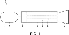
- FIG. 1 is a schematic diagram showing a rocket according to this embodiment.
- FIG. 2 is a cross-sectional view showing the oxidant tank according to this embodiment.
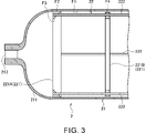
- FIG. 3 is an enlarged sectional view showing the oxidant tank according to this embodiment.
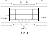
- FIG. 4 is a schematic diagram showing a state before the spinning process of the blank tube of the tank body according to the present embodiment.
- FIG. 5 is a schematic diagram showing a state during spinning processing of the blank tube of the tank body according to the present embodiment.
- FIG. 6 is a schematic diagram showing a state after spinning processing of the blank tube of the tank body according to the present embodiment.
- FIG. 1 is a schematic diagram showing a rocket 1 according to this embodiment.
- Rocket 1 is a hybrid rocket. As shown in FIG. 1, the rocket 1 includes an oxidant tank 2, an injector plate 3, an engine casing 4, and a nozzle 5.
- the oxidant tank 2 corresponds to an example of the liquid tank of the present disclosure.
- the liquid tank of the present disclosure may be a liquid tank of a rocket other than a hybrid rocket, or may be a liquid tank of a device other than a rocket.
- the oxidant tank 2 contains a liquid oxidant 6 .
- the oxidizing agent 6 include liquid oxygen, hydrogen peroxide, nitrogen tetroxide, nitrous oxide, and the like.
- the oxidant tank 2 is connected through an injector plate 3 to one end (the left end in FIG. 1) of a cylindrical engine casing 4 .
- the oxidant 6 stored in the oxidant tank 2 is injected into the engine casing 4 from injection ports (not shown) formed in the injector plate 3 .
- a solid fuel 7 is accommodated in the engine casing 4 .
- the solid fuel 7 include hydroxyl-terminated polybutadiene (HTPB), HTPB mixed with carbon black (that is, carbon fine particles), and the like.
- a through hole 8 extending in the axial direction of the engine casing 4 is formed in the solid fuel 7 .
- a solid fuel 7 is combusted by injecting an oxidant 6 into the engine casing 4 . Specifically, when the oxidant 6 flows through the through-holes 8 of the solid fuel 7, combustion takes place on the sidewalls of the through-holes 8 to generate combustion gas.
- a nozzle 5 is connected to the other end of the engine casing 4 (the right end in FIG. 1). Combustion gas generated within the engine casing 4 is ejected from a nozzle 5 . Thereby, the thrust of the rocket 1 is obtained.
- FIG. 1 The configuration of the oxidant tank 2 will be described in detail below with reference to FIGS. 2 and 3.
- FIG. 1 The configuration of the oxidant tank 2 will be described in detail below with reference to FIGS. 2 and 3.
- FIG. 1 The configuration of the oxidant tank 2 will be described in detail below with reference to FIGS. 2 and 3.
- FIG. 1 The configuration of the oxidant tank 2 will be described in detail below with reference to FIGS. 2 and 3.
- FIG. 2 is a cross-sectional view showing the oxidant tank 2 according to this embodiment.
- FIG. 3 is an enlarged sectional view showing the oxidant tank 2 according to this embodiment.
- FIG. 3 is an enlarged cross-sectional view showing the left portion of the oxidant tank 2 in FIG.
- the oxidant tank 2 includes a tank body 21 and a baffle structure 22 .
- the axial direction of the tank body 21, the circumferential direction of the tank body 21, and the radial direction of the tank body 21 are simply referred to as the axial direction, the circumferential direction, and the radial direction.
- the tank body 21 contains the liquid oxidizing agent 6 .
- the tank body 21 is seamlessly formed. In other words, the tank body 21 does not have joints such as welded or bolted joints.
- the shape of the tank main body 21 is a cylindrical shape in which both ends 211 and 212 are tapered toward the ends.
- the tank main body 21 is formed, for example, by spinning, as will be described later.
- An opening 213 is provided at the tip of the end 211 (left end in FIG. 2) of the tank body 21 .
- An opening 214 is provided at the tip of the end portion 212 (right end portion in FIG. 2) of the tank body 21 .
- Other members for example, plugs, pipes, etc. are connected to the openings 213 and 214 .
- the baffle structure 22 is provided inside the tank body 21 .
- the baffle structure 22 is a structure for suppressing sloshing of the oxidizing agent 6 inside the tank body 21 .
- the baffle structure 22 has a plurality of baffles 221 and connecting members 222 .
- the baffle 221 is an annular member.
- a plurality of baffles 221 are arranged at intervals in the axial direction of the tank body 21 .
- a plurality of baffles 221 are arranged coaxially.
- Each baffle 221 extends circumferentially along the inner peripheral surface F ⁇ b>1 of the tank body 21 .
- a plurality of baffles 221 are connected to each other by connecting members 222 .
- connection member 222 extends in the axial direction of the tank body 21.
- the connection member 222 is a rod-shaped member.
- the cross-sectional shape of the connection member 222 is not particularly limited, and may be circular or polygonal, for example.
- Connecting member 222 may be hollow or solid.
- the number of connection members 222 is not particularly limited.
- a plurality of connecting members 222 are circumferentially spaced apart.
- the connecting member 222 passes through each baffle 221.
- a member forming each baffle 221 is provided with a through hole extending in the axial direction, and the connection member 222 is inserted through the through hole.
- the connection member 222 does not have to penetrate each baffle 221 .
- Each baffle 221 is attached to a connecting member 222 by, for example, welding or bolting.
- the plurality of baffles 221 include end baffles 221A and normal baffles 221B.
- the end baffles 221A are baffles 221 located at both axial ends of the plurality of baffles 221 .
- the normal baffle 221B is one of the baffles 221 other than the end baffle 221A.
- seven normal baffles 221B are provided.
- the number of normal baffles 221B may be other than seven.
- a plurality of baffles 221 are arranged at regular intervals.
- a plurality of baffles 221 may be arranged at uneven intervals.
- the end baffle 221A is held on the inner peripheral surface F1 of the tank body 21. Specifically, the end baffle 221A is sandwiched between the inner peripheral surface F1 of the tank body 21 . As shown in FIG. 3, the outer peripheral surface F2 of the end baffle 221A is in contact with the inner peripheral surface F1 of the tank body 21. As shown in FIG. The outer peripheral surface F2 of the end baffle 221A is pressed radially inward by the inner peripheral surface F1 of the tank body 21 . Thereby, the holding of the end baffle 221A by the tank body 21 is realized.
- the holding of the end baffle 221A by the tank body 21 may be realized by a force in a direction other than the radially inward direction (for example, an axial force).
- the holding of the end baffle 221A by the tank body 21 is achieved by, for example, spinning as described later.
- the end baffle 221A is held by a portion of the inner peripheral surface F1 of the tank body 21 extending in the axial direction.
- the end baffle 221A may be held at a portion of the inner peripheral surface F1 of the tank body 21 whose diameter decreases toward the end side.
- the baffle structure 22 is held by the tank body 21 by holding the end baffle 221A on the inner peripheral surface F1 of the tank body 21 .
- the end baffle 221A is provided mainly to hold the baffle structure 22 to the tank body 21.
- the axial thickness of the end baffle 221A is normally thicker than the axial thickness of the baffle 221B.
- the axial thickness of the end baffle 221A may be the same as the axial thickness of the normal baffle 221B, or may be thinner than the axial thickness of the normal baffle 221B.
- the surface of the end baffle 221A other than the outer peripheral surface F2 is provided with an inclined surface F3 that is inclined with respect to the axial direction.
- the inclined surface F3 is inclined radially inward as it approaches the opening 213 .
- the cleaning liquid inside the tank main body 21 is smoothly discharged to the outside of the tank main body 21 .
- the inclined surface F3 may be inclined radially inward as the distance from the opening 213 increases. In this case, when the cleaning liquid is discharged from the opening 214 to the outside of the tank body 21, the cleaning liquid present on the opening 213 side of the end baffle 221A is smoothly discharged along the inclined surface F3.
- a through hole extending in the axial direction may be formed in the end baffle 221A.
- a plurality of through holes are formed in the end baffle 221A at intervals in the circumferential direction.
- the normal baffle 221B is not held on the inner peripheral surface F1 of the tank body 21.
- sloshing of the oxidant 6 inside the tank body 21 is suppressed.
- the normal baffle 221B is provided to suppress sloshing of the oxidizing agent 6 within the tank body 21 .
- the outer peripheral surface F4 of the normal baffle 221B is separated from the inner peripheral surface F1 of the tank body 21.
- the cleaning liquid in the tank body 21 is normally flushed with the outer peripheral surface F4 of the baffle 221B and the tank body 21. and the inner peripheral surface F1 of . Therefore, the cleaning liquid in the tank main body 21 is normally prevented from remaining in the tank main body 21 by being dammed up by the baffle 221B. Therefore, the cleaning liquid inside the tank main body 21 is smoothly discharged to the outside of the tank main body 21 .
- a through hole extending in the axial direction may be formed in the normal baffle 221B.
- a plurality of through holes are circumferentially spaced and typically formed in baffle 221B.
- the inner diameter of the normal baffle 221B may be the same as or different from the inner diameter of the end baffle 221A (that is, the minimum diameter of the inclined surface F3).
- the oxidant tank 2 includes the seamless tank main body 21 . Furthermore, the baffle structure 22 is held by the tank body 21 by holding the end baffle 221A on the inner peripheral surface F1 of the tank body 21 . Thereby, the baffle 221 is provided in the tank body 21 with a simple structure. If the tank main body 21 has joints such as welded or bolted joints, it may be necessary to consider welding weaknesses or defects in the design, or it may be necessary to inspect the welded portions of the oxidizer tank 2 . The manufacturing process of the oxidant tank 2 has tended to become redundant due to such occurrences.
- the tank body 21 is seamless, and the baffle 221 is provided in the tank body 21 with a simple structure. , and the weld inspection process can be eliminated, shortening the manufacturing process. As a result, the procurement period, manufacturing cost, and inspection cost of the oxidant tank 2 can be reduced. Furthermore, the weight of the oxidant tank 2 can be reduced as compared with the case where the tank main body 21 has joints formed by welding, bolting, or the like. Furthermore, safety can be improved. Furthermore, sloshing can be appropriately suppressed.
- the end baffle 221A is sandwiched between the inner peripheral surface F1 of the tank body 21.
- the end baffle 221A may be welded to the inner peripheral surface F1 of the tank body 21 .
- the end baffle 221A is sandwiched between the inner peripheral surfaces F1 of the tank body 21 as in the above example. preferably.
- the procurement period, manufacturing cost, and inspection cost of the oxidant tank 2 can be further reduced.
- the weight of the oxidant tank 2 can be reduced and the safety can be improved.
- the baffles 221 located at both ends in the axial direction are held on the inner peripheral surface F1 of the tank body 21.
- at least one of the plurality of baffles 221 should be held on the inner peripheral surface F1 of the tank body 21 .
- one or a plurality of baffles 221 located at positions other than both ends in the axial direction may be held on the inner peripheral surface F ⁇ b>1 of the tank body 21 .
- each baffle 221 is connected to each other by connecting members 222 .
- the connection member 222 may be omitted from the configuration of the oxidant tank 2 .
- each baffle 221 is held on the inner peripheral surface F ⁇ b>1 of the tank body 21 .
- it is preferable that the plurality of baffles 221 are connected to each other by connecting members 222 from the viewpoint of reducing the locations (for example, welding locations) where the baffles 221 are held in the oxidant tank 2 .
- the end baffles 221A (that is, the baffles 221 located at both ends in the axial direction among the plurality of baffles 221) are held on the inner peripheral surface F1 of the tank body 21, and the baffle structure 22 is held on the tank body 21.
- the number of locations where the baffle 221 is held in the oxidant tank 2 (for example, welding locations) is effectively reduced.
- FIGS. 4 to 6 A method of manufacturing the oxidant tank 2 will be described with reference to FIGS.
- each constituent element is simplified compared to FIGS. 2 and 3 for easy understanding.
- the number of normal baffles 221B in baffle structure 22 is reduced compared to FIGS.
- the tank body 21 is formed by spinning, for example.
- a baffle structure 22 is installed in the cylindrical blank tube 23 before the spinning process is performed. After that, the tank main body 21 is formed by spinning the raw pipe 23 .
- FIG. 4 is a schematic diagram showing the state before the spinning process of the blank tube 23 of the tank body 21 according to the present embodiment.
- the thickness of the central portion 231 in the axial direction of the blank pipe 23 is thinner than the thickness of both end portions 232 and 233 of the blank pipe 23 .
- the inner diameter of the central portion 231 is the same as the inner diameters of the end portions 232 and 233 .
- the outer diameter of the central portion 231 is smaller than the outer diameters of the end portions 232 and 233 .
- the blank tube 23 is formed by flow forming, for example.
- the baffle structure 22 is installed in such a base pipe 23 so that the direction in which the plurality of baffles 221 are arranged coincides with the axial direction of the base pipe 23 . Thereby, a plurality of baffles 221 are installed in the blank tube 23 at intervals in the axial direction of the blank tube 23 .
- the axial position of the end baffle 221A is near the axial position of the connecting portion between the central portion 231 of the blank tube 23 and the end portions 232 and 233 .
- the baffle structure 22 is installed using a jig, for example. The jig is removed at an appropriate time during the spinning process.
- FIG. 5 is a schematic diagram showing a state during spinning processing of the blank tube 23 of the tank body 21 according to the present embodiment.
- FIG. 6 is a schematic diagram showing a state after spinning processing of the blank tube 23 of the tank body 21 according to the present embodiment.
- the raw pipe 23 is deformed by pressing a tool against the raw pipe 23 from the outside in the radial direction while the raw pipe 23 is being rotated.
- both end portions 232 and 233 of the blank pipe 23 are reduced in diameter as they proceed toward the ends.
- both ends 232, 233 of the base tube 23 sandwich the end baffle 221A while deforming.
- FIG. 5 is a schematic diagram showing a state during spinning processing of the blank tube 23 of the tank body 21 according to the present embodiment.
- FIG. 6 is a schematic diagram showing a state after spinning processing of the blank tube 23 of the tank body 21 according to the present embodiment.
- FIG. 6 shows a state in which the formation of the tank body 21 is completed and the end baffle 221A is held on the inner peripheral surface F1 of the tank body 21. As shown in FIG. As described above, the end baffle 221A is sandwiched between the inner peripheral surface F1 of the tank body 21 while the seamless tank body 21 is formed by the spinning process.
- the method of manufacturing the oxidant tank 2 includes a step of installing a plurality of baffles 221 in the cylindrical blank pipe 23 at intervals in the axial direction of the blank pipe 23 . Furthermore, in the method of manufacturing the oxidant tank 2, after installing the plurality of baffles 221 in the raw pipe 23, the diameters of both ends 232 and 233 of the raw pipe 23 are reduced toward the ends, thereby forming a seamless tank body. 21. Thereby, forming a seamless tank body 21 and providing a plurality of baffles 221 within the tank body 21 are suitably realized. Therefore, the manufacturing process of the oxidant tank 2 is shortened. As a result, the procurement period, manufacturing cost, and inspection cost of the oxidant tank 2 can be reduced. Furthermore, the weight of the oxidant tank 2 can be reduced and the safety can be improved. Furthermore, sloshing can be appropriately suppressed.
- the end baffle 221A is sandwiched between the inner peripheral surface F1 of the tank main body 21 by spinning the blank tube 23 .
- the end baffle 221A may be welded to the inner peripheral surface F1 of the tank body 21 as described above.
- the blank pipe 23 is prepared by flow forming.
- the blank tube 23 may be prepared by spinning.
- the diameters of the both end portions 232 and 233 of the blank tube 23 are reduced by the spinning process toward the end side.
- both ends 232 and 233 of the raw tube 23 may be reduced in diameter as they progress toward the ends by flow forming.
- the liquid tank of the present disclosure is the oxidant tank 2 of the rocket 1, which is a hybrid rocket
- the liquid tank of the present disclosure may be a liquid tank for rockets other than hybrid rockets.
- the liquid tank of the present disclosure may be a liquid rocket oxidant tank or fuel tank comprising a liquid oxidant and a liquid fuel.
- the liquid tank of the present disclosure may be a liquid tank for devices other than rockets (eg, vehicles, etc.).
- the thickness of the liquid tank does not change much regardless of the size of the rocket. Therefore, in large rockets, the liquid tanks are a smaller percentage of the total rocket weight than in small or medium rockets.
- the liquid tanks make up a greater proportion of the total weight of the rocket than in larger rockets. Therefore, for small or medium-sized rockets, it is more desirable to reduce the weight of liquid tanks.
- Rocket 2 Oxidizer tank (liquid tank) 21: Tank body 23: Element tube 211: End 212: End 221: Baffle 221A: End baffle 221B: Normal baffle 222: Connecting member 232: End 233: End Part F1: inner peripheral surface F2: outer peripheral surface F3: inclined surface F4: outer peripheral surface
Landscapes
- Engineering & Computer Science (AREA)
- Mechanical Engineering (AREA)
- Chemical & Material Sciences (AREA)
- Combustion & Propulsion (AREA)
- Remote Sensing (AREA)
- Aviation & Aerospace Engineering (AREA)
- General Engineering & Computer Science (AREA)
- Filling Or Discharging Of Gas Storage Vessels (AREA)
Priority Applications (3)
| Application Number | Priority Date | Filing Date | Title |
|---|---|---|---|
| EP22816151.9A EP4350196A4 (en) | 2021-06-01 | 2022-06-01 | LIQUID TANK, ROCKET AND METHOD FOR MANUFACTURING LIQUID TANK |
| JP2023525890A JP7644432B2 (ja) | 2021-06-01 | 2022-06-01 | 液体タンク、ロケット、および、液体タンクの製造方法 |
| US18/523,093 US20240102614A1 (en) | 2021-06-01 | 2023-11-29 | Liquid tank, rocket, and method of manufacturing liquid tank |
Applications Claiming Priority (2)
| Application Number | Priority Date | Filing Date | Title |
|---|---|---|---|
| JP2021092569 | 2021-06-01 | ||
| JP2021-092569 | 2021-06-01 |
Related Child Applications (1)
| Application Number | Title | Priority Date | Filing Date |
|---|---|---|---|
| US18/523,093 Continuation US20240102614A1 (en) | 2021-06-01 | 2023-11-29 | Liquid tank, rocket, and method of manufacturing liquid tank |
Publications (1)
| Publication Number | Publication Date |
|---|---|
| WO2022255405A1 true WO2022255405A1 (ja) | 2022-12-08 |
Family
ID=84324155
Family Applications (1)
| Application Number | Title | Priority Date | Filing Date |
|---|---|---|---|
| PCT/JP2022/022288 Ceased WO2022255405A1 (ja) | 2021-06-01 | 2022-06-01 | 液体タンク、ロケット、および、液体タンクの製造方法 |
Country Status (4)
| Country | Link |
|---|---|
| US (1) | US20240102614A1 (https=) |
| EP (1) | EP4350196A4 (https=) |
| JP (1) | JP7644432B2 (https=) |
| WO (1) | WO2022255405A1 (https=) |
Families Citing this family (3)
| Publication number | Priority date | Publication date | Assignee | Title |
|---|---|---|---|---|
| US12214911B2 (en) * | 2021-08-03 | 2025-02-04 | The Boeing Compnay | Load coupling attachment systems and methods |
| JP2023142362A (ja) * | 2022-03-25 | 2023-10-05 | サムテック株式会社 | 容器及び容器の製造方法 |
| US12578058B2 (en) * | 2022-11-25 | 2026-03-17 | H2CREO Corp. | Liquid hydrogen fuel tank and liquid hydrogen storage device including same |
Citations (7)
| Publication number | Priority date | Publication date | Assignee | Title |
|---|---|---|---|---|
| US20060145022A1 (en) * | 2004-12-10 | 2006-07-06 | Buehler David B | Propellant tank baffle system |
| JP2011020880A (ja) | 2009-07-15 | 2011-02-03 | Ihi Aerospace Co Ltd | ハイブリッドロケットの固体燃料 |
| JP2011183841A (ja) * | 2010-03-04 | 2011-09-22 | Japan Aerospace Exploration Agency | 推進薬タンク及びこの推進薬タンクを用いた蒸気噴射装置 |
| JP2017517705A (ja) * | 2014-05-20 | 2017-06-29 | スチールヘッド コンポジッツ,エルエルシー. | 極性ボスを備える金属ライナー圧力容器 |
| JP2017133693A (ja) * | 2016-01-27 | 2017-08-03 | 株式会社旭製作所 | 継目無容器、その製造方法、複合容器、及びその製造方法 |
| JP2019513608A (ja) * | 2016-04-05 | 2019-05-30 | ノースロップ・グラマン・イノベーション・システムズ・インコーポレーテッド | 宇宙飛行体のための液体貯蔵タンクおよびシステムおよび推進システムならびに関連する方法 |
| JP2021092569A (ja) | 2015-08-03 | 2021-06-17 | ノバルティス アーゲー | 血液学的毒性バイオマーカーとしてのgdf−15 |
Family Cites Families (4)
| Publication number | Priority date | Publication date | Assignee | Title |
|---|---|---|---|---|
| US7431756B2 (en) * | 2002-05-09 | 2008-10-07 | Ovonic Hydrogen Systems Llc | Modular metal hydride hydrogen storage system |
| CN204805946U (zh) * | 2015-04-15 | 2015-11-25 | 石家庄安瑞科气体机械有限公司 | 固态高压混合储氢装置 |
| WO2016172430A1 (en) * | 2015-04-22 | 2016-10-27 | Keystone Engineering Company | Center of mass control of liquid tanks for spacecraft use |
| DK3348822T3 (da) * | 2017-01-13 | 2020-07-06 | Orbital Express Launch Ltd | Raketdrivmiddeltankarrangement, raketfremdriftsenhed og raket |
-
2022
- 2022-06-01 WO PCT/JP2022/022288 patent/WO2022255405A1/ja not_active Ceased
- 2022-06-01 JP JP2023525890A patent/JP7644432B2/ja active Active
- 2022-06-01 EP EP22816151.9A patent/EP4350196A4/en active Pending
-
2023
- 2023-11-29 US US18/523,093 patent/US20240102614A1/en active Pending
Patent Citations (7)
| Publication number | Priority date | Publication date | Assignee | Title |
|---|---|---|---|---|
| US20060145022A1 (en) * | 2004-12-10 | 2006-07-06 | Buehler David B | Propellant tank baffle system |
| JP2011020880A (ja) | 2009-07-15 | 2011-02-03 | Ihi Aerospace Co Ltd | ハイブリッドロケットの固体燃料 |
| JP2011183841A (ja) * | 2010-03-04 | 2011-09-22 | Japan Aerospace Exploration Agency | 推進薬タンク及びこの推進薬タンクを用いた蒸気噴射装置 |
| JP2017517705A (ja) * | 2014-05-20 | 2017-06-29 | スチールヘッド コンポジッツ,エルエルシー. | 極性ボスを備える金属ライナー圧力容器 |
| JP2021092569A (ja) | 2015-08-03 | 2021-06-17 | ノバルティス アーゲー | 血液学的毒性バイオマーカーとしてのgdf−15 |
| JP2017133693A (ja) * | 2016-01-27 | 2017-08-03 | 株式会社旭製作所 | 継目無容器、その製造方法、複合容器、及びその製造方法 |
| JP2019513608A (ja) * | 2016-04-05 | 2019-05-30 | ノースロップ・グラマン・イノベーション・システムズ・インコーポレーテッド | 宇宙飛行体のための液体貯蔵タンクおよびシステムおよび推進システムならびに関連する方法 |
Non-Patent Citations (1)
| Title |
|---|
| See also references of EP4350196A4 |
Also Published As
| Publication number | Publication date |
|---|---|
| EP4350196A1 (en) | 2024-04-10 |
| JPWO2022255405A1 (https=) | 2022-12-08 |
| JP7644432B2 (ja) | 2025-03-12 |
| US20240102614A1 (en) | 2024-03-28 |
| EP4350196A4 (en) | 2025-05-07 |
Similar Documents
| Publication | Publication Date | Title |
|---|---|---|
| WO2022255405A1 (ja) | 液体タンク、ロケット、および、液体タンクの製造方法 | |
| US7735473B2 (en) | Connection head structure of high pressure fuel injection tube | |
| US8858224B2 (en) | Detonation wave arrestor | |
| RU2232916C2 (ru) | Топливная форсунка жидкостного ракетного двигателя (варианты) | |
| CN1050891C (zh) | 干燥低氧化氮的多喷嘴燃烧火焰筒罩部件 | |
| CN109798202B (zh) | 一种集电点火器于一体的液体火箭发动机喷注器 | |
| US8607457B2 (en) | Method for welding components with a closed hollow cross-section in such a way that a peripheral gap is produced between the two overlapping components | |
| KR102434970B1 (ko) | 산화제 및 연료를 이용하는 로켓 엔진 연소기의 재생 냉각 추력실 및 이를 포함하는 로켓 | |
| JP2007255795A (ja) | 燃焼器用バーナ及び燃焼方法 | |
| US20060096262A1 (en) | Apparatus and method for an exhaust aftertreatment device | |
| US8015707B2 (en) | Method of fabricating a combustion chamber | |
| WO2020257649A1 (en) | Reaction control vortex thruster system | |
| CN113530712A (zh) | 一种三击式喷注器 | |
| CN111502860A (zh) | 一种模块化设计的压力旋流喷注器 | |
| CN117190051B (zh) | 一种冲压发动机环形气瓶及其无飞溅电子束焊接方法 | |
| JP2024078265A (ja) | 締結構造、ロケット、および、円筒部材の製造方法 | |
| CN114251195B (zh) | 一种多次起动推力室头部结构及推力室 | |
| CN205206992U (zh) | 一种燃气发生器壳体 | |
| KR100925540B1 (ko) | 수직 분리판 및 수평 분리판을 구비하는 액체로켓엔진용연소기 헤드 | |
| CN104525670A (zh) | 一种铼铱发动机燃烧室内壁防护铂铑环的制备方法 | |
| JP2008111340A (ja) | ロケット用噴射器及び燃焼器 | |
| JPH07310594A (ja) | ハイブリッドロケットモータの固体燃料グレイン | |
| JPS61119920A (ja) | ガスタ−ビン燃焼器 | |
| KR20220077612A (ko) | 로켓엔진용 가스점화기 | |
| CN223426166U (zh) | 一种喷管液压检验及爆破试验工装 |
Legal Events
| Date | Code | Title | Description |
|---|---|---|---|
| 121 | Ep: the epo has been informed by wipo that ep was designated in this application |
Ref document number: 22816151 Country of ref document: EP Kind code of ref document: A1 |
|
| WWE | Wipo information: entry into national phase |
Ref document number: 2023525890 Country of ref document: JP |
|
| WWE | Wipo information: entry into national phase |
Ref document number: 2022816151 Country of ref document: EP |
|
| NENP | Non-entry into the national phase |
Ref country code: DE |
|
| ENP | Entry into the national phase |
Ref document number: 2022816151 Country of ref document: EP Effective date: 20240102 |