WO2022255330A1 - 室内機 - Google Patents
室内機 Download PDFInfo
- Publication number
- WO2022255330A1 WO2022255330A1 PCT/JP2022/022037 JP2022022037W WO2022255330A1 WO 2022255330 A1 WO2022255330 A1 WO 2022255330A1 JP 2022022037 W JP2022022037 W JP 2022022037W WO 2022255330 A1 WO2022255330 A1 WO 2022255330A1
- Authority
- WO
- WIPO (PCT)
- Prior art keywords
- indoor unit
- communication
- outdoor unit
- frequency
- circuit
- Prior art date
Links
- 238000004891 communication Methods 0.000 claims abstract description 250
- 230000005540 biological transmission Effects 0.000 claims abstract description 109
- 238000000034 method Methods 0.000 claims description 6
- 239000003507 refrigerant Substances 0.000 description 93
- 238000004378 air conditioning Methods 0.000 description 18
- 230000008878 coupling Effects 0.000 description 14
- 238000010168 coupling process Methods 0.000 description 14
- 238000005859 coupling reaction Methods 0.000 description 14
- 238000010586 diagram Methods 0.000 description 10
- 238000009499 grossing Methods 0.000 description 7
- 230000006870 function Effects 0.000 description 5
- 230000004048 modification Effects 0.000 description 4
- 238000012986 modification Methods 0.000 description 4
- 102100035353 Cyclin-dependent kinase 2-associated protein 1 Human genes 0.000 description 3
- 239000007788 liquid Substances 0.000 description 3
- 238000005057 refrigeration Methods 0.000 description 3
- XLYOFNOQVPJJNP-UHFFFAOYSA-N water Substances O XLYOFNOQVPJJNP-UHFFFAOYSA-N 0.000 description 3
- 230000006835 compression Effects 0.000 description 2
- 238000007906 compression Methods 0.000 description 2
- 238000009434 installation Methods 0.000 description 2
- 230000010349 pulsation Effects 0.000 description 2
- 238000007664 blowing Methods 0.000 description 1
- 239000003990 capacitor Substances 0.000 description 1
- 230000002860 competitive effect Effects 0.000 description 1
- 239000000470 constituent Substances 0.000 description 1
- 230000009897 systematic effect Effects 0.000 description 1
Images


Classifications
-
- F—MECHANICAL ENGINEERING; LIGHTING; HEATING; WEAPONS; BLASTING
- F24—HEATING; RANGES; VENTILATING
- F24F—AIR-CONDITIONING; AIR-HUMIDIFICATION; VENTILATION; USE OF AIR CURRENTS FOR SCREENING
- F24F11/00—Control or safety arrangements
- F24F11/50—Control or safety arrangements characterised by user interfaces or communication
- F24F11/54—Control or safety arrangements characterised by user interfaces or communication using one central controller connected to several sub-controllers
-
- F—MECHANICAL ENGINEERING; LIGHTING; HEATING; WEAPONS; BLASTING
- F24—HEATING; RANGES; VENTILATING
- F24F—AIR-CONDITIONING; AIR-HUMIDIFICATION; VENTILATION; USE OF AIR CURRENTS FOR SCREENING
- F24F11/00—Control or safety arrangements
- F24F11/88—Electrical aspects, e.g. circuits
-
- F—MECHANICAL ENGINEERING; LIGHTING; HEATING; WEAPONS; BLASTING
- F24—HEATING; RANGES; VENTILATING
- F24F—AIR-CONDITIONING; AIR-HUMIDIFICATION; VENTILATION; USE OF AIR CURRENTS FOR SCREENING
- F24F11/00—Control or safety arrangements
- F24F11/50—Control or safety arrangements characterised by user interfaces or communication
- F24F11/56—Remote control
-
- H—ELECTRICITY
- H04—ELECTRIC COMMUNICATION TECHNIQUE
- H04B—TRANSMISSION
- H04B3/00—Line transmission systems
- H04B3/54—Systems for transmission via power distribution lines
Definitions
- Patent Document 1 Japanese Patent Laid-Open No. 2013-137119
- an air conditioner there are cases where communication is performed by wiring for supplying power by connecting an outdoor unit and an indoor unit.
- the number of indoor units connected to one outdoor unit is small, so the outdoor unit and the indoor unit are directly connected by wiring to generate electric power. It is easy to configure for feeding. Therefore, multi-type air conditioners for stores and air conditioners for homes are sometimes configured to supply electric power by directly connecting the outdoor unit and the indoor unit by wiring.
- the indoor unit described in Patent Document 1 can also be used for multi-type air conditioners for buildings, a large number of indoor units are connected to one outdoor unit. It becomes difficult to adopt a configuration similar to that of an air conditioner for commercial use. For example, in multi-type air conditioners for buildings, if power is supplied from one outdoor unit to many indoor units, the wiring becomes long and the power supply unit of the outdoor unit becomes large-scaled. . Therefore, in multi-type air conditioners for buildings, the indoor units are configured to receive power supply from sources other than the outdoor units.
- An indoor unit that can be applied to such multiple types of air conditioners has a problem of recognizing a physical connection with an outdoor unit in a communication state suitable for each type of air conditioner. .
- the indoor unit in the first aspect is an indoor unit included in an air conditioner equipped with an outdoor unit.
- the indoor unit includes a power receiving circuit, a first receiving circuit, a transmitting/receiving circuit, and a controller.
- the power receiving circuit can be connected to the outdoor unit to receive power through the outdoor unit, and can be connected to a device other than the outdoor unit to receive power.
- the first receiving circuit can receive a current signal transmitted from the outdoor unit using a current loop formed by a power line included in the power supply wiring.
- Transceiver circuitry is capable of transmitting and receiving voltage signals for communications using voltage variations.
- the control unit relates to a first communication state for recognizing a physical connection with the outdoor unit and a second communication state for communicating with the outdoor unit for operating the air conditioner. Selecting use of the transmitting/receiving circuit and the first receiving circuit in the second communication state.
- the indoor unit of the first aspect when the outdoor unit and the power receiving circuit are connected by power supply wiring, it is possible to recognize the physical connection with the outdoor unit by using communication using a current loop that is resistant to noise. When it is not connected to the outdoor unit by power supply wiring, it is possible to recognize the physical connection with the outdoor unit by communication using a transmitting/receiving circuit other than current loop communication.
- the indoor unit of the second aspect is the indoor unit of the first aspect, in which the frequency used for communication by the transmission/reception circuit is higher than the frequency used for communication by the first reception circuit.
- the indoor unit according to the third aspect is the indoor unit according to the first aspect or the second aspect, wherein the control unit receives the first reception in the first communication state when receiving the current signal and the voltage signal.
- a circuit and a transmitting/receiving circuit are used, and the transmitting/receiving circuit is used without using the first receiving circuit in the second communication state.
- the indoor unit of the third aspect when the outdoor unit and the power receiving circuit are connected by the power supply wiring, by using the power supply wiring with low impedance and using the communication by the current loop that is resistant to noise, the physical connection with the outdoor unit is reduced. connection can be reliably recognized.
- the indoor unit according to the fourth aspect is the indoor unit according to the third aspect, wherein, in the first communication state, the controller controls the frequency of the current signal received by the first receiving circuit as the frequency of the power supply applied to the power supply wiring. are the same.
- the power frequency supplied from the power supply can be used as the source of the current signal of the outdoor unit, which makes it easier to simplify the configuration of the outdoor unit connected to the indoor unit.
- the indoor unit according to the fifth aspect is the indoor unit according to any one of the first aspect to the fourth aspect, and the transmitting/receiving circuit transmits/receives voltage signals by a communication method of power line communication and multi-channel communication.
- the indoor unit of the sixth aspect is the indoor unit of the first aspect or the second aspect, and the transmitting/receiving circuit can transmit and receive using a signal line other than the power supply wiring.
- the indoor unit of the sixth aspect even when the power receiving circuit is connected to a device other than the outdoor unit, it is possible to communicate with the outdoor unit for the operation of the air conditioner using a signal line other than the power supply wiring.
- the indoor unit according to the seventh aspect is the indoor unit according to the sixth aspect, and includes a second receiving circuit that receives a low-frequency voltage signal for communication using voltage changes using a signal line other than the power supply wiring.
- the transmission/reception circuit transmits/receives a high-frequency voltage signal having a higher frequency than the low-frequency voltage signal.
- the control unit uses the second receiving circuit and the transmitting/receiving circuit without using the first receiving circuit in the first communication state, and switches to the second communication state.
- the transmitting/receiving circuit is used without using the first receiving circuit and the second receiving circuit.
- the indoor unit of the eighth aspect is the indoor unit of the seventh aspect, wherein the first receiving circuit is a current loop communication circuit capable of transmitting and receiving a current signal to and from the outdoor unit using the current loop. .
- the control unit fails to recognize the physical connection with the outdoor unit in the first communication state, the control unit does not use the second receiving circuit and the transmitting/receiving circuit in the second communication state. Transmission and reception with the outdoor unit are performed using the current loop communication circuit.
- the indoor unit in the case of a connection in which one indoor unit is always determined when viewed from one outdoor unit, it is also possible to correspond to a form in which communication with the outdoor unit is performed using only the current loop.
- FIG. 1 is a schematic diagram showing an example of a configuration of a multi-type air conditioner for buildings;
- FIG. 1 is a schematic diagram showing an example of the configuration of a commercial air conditioner;
- FIG. 3 is a schematic diagram showing another example of the configuration of a commercial air conditioner;
- BRIEF DESCRIPTION OF THE DRAWINGS It is a schematic diagram which shows an example of a structure of a residential air conditioner.
- FIG. 3 is a schematic diagram showing another example of the configuration of a residential air conditioner; It is a block diagram which shows an example of a structure of an indoor unit.
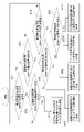
- 4 is a flow chart showing an example of a procedure for determining an air conditioner in which an indoor unit is incorporated.
- 4 is a flow chart showing an example of the operation of the air conditioner for system recognition.
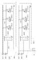
- FIG. 2 is a block diagram for explaining a configuration related to communication between an outdoor unit and an indoor unit forming a commercial air conditioner
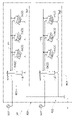
- FIG. 10 is a block diagram showing an example of connection of a plurality of indoor units in the air conditioner of FIG. 9
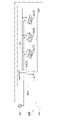
- FIG. 2 is a block diagram for explaining a configuration related to communication between an outdoor unit and an indoor unit forming a building multi-type air conditioner
- FIG. 12 is a block diagram showing an example of connection of a plurality of indoor units in the air conditioner of FIG. 11;
- the air conditioner 110 shown in FIG. 1 includes a plurality of outdoor units 2, a plurality of indoor units 3, and a centralized controller. 4.
- a plurality of outdoor units 2, a plurality of indoor units 3, and a centralized controller 4 are connected so as to be able to communicate with each other, and perform air conditioning of a target space.
- the plurality of outdoor units 2 and the plurality of indoor units 3 are equipped with, for example, heat exchangers for air conditioning.
- the air conditioner 110 includes the centralized controller 4 will be described, but the air conditioner 110 may not include the centralized controller 4 .
- the air conditioner 110 is a multi-type for buildings.
- the outdoor unit 2 is connected to a commercial power source 901 to supply power to the outdoor unit 2
- the indoor unit 3 is connected to a commercial power source 902 to supply power to the indoor unit 3. It is connected.
- the commercial power supply 901 for driving the outdoor unit 2 and the commercial power supply 902 for driving the indoor unit 3 are separate systems.
- the plurality of outdoor units 2 include a first outdoor unit 2a and a second outdoor unit 2b.
- the plurality of indoor units 3 include a first indoor unit 3a, a second indoor unit 3b, a third indoor unit 3c, a fourth indoor unit 3d, a fifth indoor unit 3e and a sixth indoor unit 3f.
- the air conditioner 110 includes two refrigerant systems, a first refrigerant system RS1 and a second refrigerant system RS2.
- the first outdoor unit 2a, the first indoor unit 3a, the second indoor unit 3b, and the third indoor unit 3c form a first refrigerant circuit RC1 that forms the core of the first refrigerant system RS1. Therefore, the first outdoor unit 2a, the first indoor unit 3a, the second indoor unit 3b, and the third indoor unit 3c are connected by the refrigerant pipe P1, and the same refrigerant circulates through the outdoor unit 2 and the indoor unit 3. ing.
- the first refrigerant system RS1 includes a centralized controller 4 used for managing or operating the first refrigerant circuit RC1.
- the second outdoor unit 2b, fourth indoor unit 3d, fifth indoor unit 3e, and sixth indoor unit 3f form a second refrigerant circuit RC2 that forms the core of the second refrigerant system RS2. Therefore, the second outdoor unit 2b, the fourth indoor unit 3d, the fifth indoor unit 3e, and the sixth indoor unit 3f are connected by the refrigerant pipe P2, and the same refrigerant circulates through the outdoor unit 2 and the indoor unit 3. ing.
- the second refrigerant system RS2 includes a centralized controller 4 used for managing or operating the second refrigerant circuit RC2.
- the air conditioner 121 shown in FIG. 2 is the multi-type air conditioner for buildings in FIG. Like the harmony machine 110 , it has a plurality of outdoor units 2 , a plurality of indoor units 3 , and a centralized controller 4 . In the commercial air conditioner 121 as well, a plurality of outdoor units 2, a plurality of indoor units 3, and a centralized controller 4 are connected so as to be able to communicate with each other, and perform air conditioning of the target space.
- the air conditioner 121 is a commercial air conditioner. Unlike the building multi-type air conditioner 110, the commercial air conditioner 121 is connected to the commercial power supply 901 to supply power to the outdoor unit 2, and supplies power to the indoor unit 3. is performed from the commercial power source 901 via the outdoor unit 2, for example. As described above, in the commercial air conditioner 121, the commercial power source 901 for driving the outdoor unit 2 and the indoor unit 3 is of the same system.
- the plurality of outdoor units 2 include a first outdoor unit 2a and a second outdoor unit 2b.
- the plurality of indoor units 3 include a first indoor unit 3a, a second indoor unit 3b, a third indoor unit 3c, a fourth indoor unit 3d, a fifth indoor unit 3e and a sixth indoor unit 3f.
- the air conditioner 121 includes two refrigerant systems, a first refrigerant system RS1 and a second refrigerant system RS2.
- the first outdoor unit 2a, the first indoor unit 3a, the second indoor unit 3b, and the third indoor unit 3c form a first refrigerant circuit RC1 that forms the core of the first refrigerant system RS1. Therefore, the first outdoor unit 2a, the first indoor unit 3a, the second indoor unit 3b, and the third indoor unit 3c are connected by the refrigerant pipe P1, and the same refrigerant circulates through the outdoor unit 2 and the indoor unit 3. ing.
- the first refrigerant system RS1 includes a centralized controller 4 used for managing or operating the first refrigerant circuit RC1.
- the second outdoor unit 2b, fourth indoor unit 3d, fifth indoor unit 3e, and sixth indoor unit 3f form a second refrigerant circuit RC2 that forms the core of the second refrigerant system RS2. Therefore, the second outdoor unit 2b, the fourth indoor unit 3d, the fifth indoor unit 3e, and the sixth indoor unit 3f are connected by the refrigerant pipe P2, and the same refrigerant circulates through the outdoor unit 2 and the indoor unit 3. ing.
- the second refrigerant system RS2 includes a centralized controller 4 used for managing or operating the second refrigerant circuit RC2.
- the commercial air conditioner 122 is also different from the building multi-type air conditioner 110 in that the outdoor unit 2 is connected to the commercial power supply 901 for power supply to the outdoor unit 2, and the power supply to the indoor unit 3 is performed. is performed from the commercial power source 901 via the outdoor unit 2, for example.
- the plurality of indoor units 3 include a first indoor unit 3a, a second indoor unit 3b and a third indoor unit 3c.
- the outdoor unit 2, the first indoor unit 3a, the second indoor unit 3b, and the third indoor unit 3c form a first refrigerant circuit RC1 that forms the core of the first refrigerant system RS1. Therefore, the outdoor unit 2, the first indoor unit 3a, the second indoor unit 3b, and the third indoor unit 3c are connected by the refrigerant pipe P1, and the same refrigerant circulates through the outdoor unit 2 and the plurality of indoor units 3. ing.
- the air conditioner 131 shown in FIG. 4 is the commercial air conditioner shown in FIG. Like 121, it has an outdoor unit 2, an indoor unit 3, and a centralized controller 4. However, the residential air conditioner 131 includes one outdoor unit 2 and one indoor unit 3, which are paired with each other. In the residential air conditioner 131, the outdoor unit 2 and the indoor unit 3 are connected so as to be able to communicate with each other, and the indoor unit 3 and the centralized controller 4 are connected so as to be able to communicate with each other. Air conditioning.
- the residential air conditioner 131 is also connected to the commercial power source 901 for power supply to the outdoor unit 2, and the power supply to the indoor unit 3 is For example, it is performed from the commercial power source 901 via the outdoor unit 2 .
- the commercial power supply 901 for driving the outdoor unit 2 and the indoor unit 3 is of the same system.
- the outdoor unit 2 and the indoor unit 3 are connected by a refrigerant pipe P1, and the same refrigerant circulates through the one outdoor unit 2 and the one indoor unit 3.
- the first refrigerant circuit RC1 includes only one outdoor unit 2 and one indoor unit 3, and the devices belonging to the first refrigerant system RS1, which is a refrigerant system, are connected to the outdoor units 2 and 1. It is limited to the connection with the indoor unit 3 of the base. Therefore, in the residential air conditioner 131, there is no need to perform system recognition for recognizing to which refrigerant system a plurality of indoor units 3, which will be described later, belong.
- a centralized controller 4 used for managing or operating the indoor unit 3 is connected to the indoor unit 3 .
- the residential air conditioner 132 shown in FIG. 5 is similar to the residential air conditioner 131 shown in FIG. differs in that the centralized controller 4 is not provided. However, the residential air conditioner 132 shown in FIG. 5 has the same configuration as the residential air conditioner 131 shown in FIG. 4 except that the centralized controller 4 is not provided.
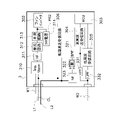
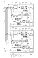
- FIG. 6 shows an example of an internal configuration mainly related to an electric system among the internal configurations of the indoor unit 3.
- the indoor unit 3 includes a power receiving circuit PR2 for receiving power from a commercial power supply 901 via the outdoor unit 2 shown in FIGS. 2 to 5 and supplying power to devices inside the indoor unit 3. ing.
- the power receiving circuit PR2 can also be connected to a commercial power supply 902 to receive power from the commercial power supply 902, as shown in FIG.
- the indoor unit 3 includes a fan inverter 302, an MCU 303, a high-frequency transmitting/receiving circuit 304, a low-frequency receiving circuit 305, and a low-frequency transmitting/receiving circuit 306, which are driven by power supplied to the interior of the indoor unit 3 by the power receiving circuit PR2.
- the fan inverter 302 is an inverter for operating a fan (not shown) that generates an airflow of indoor air in an indoor heat exchanger (not shown) provided in the indoor unit 3 .
- the MCU 303 functions as a control unit for controlling internal devices of each indoor unit 3 .
- the power receiving circuit PR2 includes an impedance upper 310, a third noise filter 311, a rectifying circuit 312, a smoothing circuit 313, and a switching power supply 314.
- the impedance upper 310 raises the impedance of the power receiving circuit PR2 to suppress the current loop communication signal performed through the current loop CL from being sucked into the power receiving circuit PR2.
- Third noise filter 311 reduces noise contained in power supplied from commercial power source 901 or commercial power source 902 .
- the rectifier circuit 312 performs rectification to convert the AC power whose noise has been reduced by the noise filter 211 into DC power, and outputs the DC power. Smoothing circuit 313 reduces pulsation contained in the output of rectifying circuit 312 .
- the DC power output from the smoothing circuit 313 is supplied to the fan inverter 302 and switching power supply 314 .
- the switching power supply 314 converts the voltage supplied from the smoothing circuit 313 into a DC voltage smaller than that, and supplies the DC voltage to the equipment inside the indoor unit 3 .
- the switching power supply 314 supplies electric power to the MCU 303, the high frequency transmission/reception circuit 304, the low frequency reception circuit 305, and the low frequency transmission/reception circuit 306, for example.
- the indoor unit 3 can form a current loop CL with the outdoor unit 2 by the power line L1 in the power supply wiring W1 and the signal line L2 other than the power supply wiring W1.
- the indoor unit 3 can transmit and receive a low-frequency current signal via the current loop CL by the low-frequency transmission/reception circuit 306 .
- the indoor unit 3 includes a bandpass filter 321, a coupling circuit 322, and a fourth noise filter 323.
- the band-pass filter 321 passes high-frequency voltage signals transmitted and received by the high-frequency transmission/reception circuit 304 .
- the bandpass filter 321 is connected to the wiring of the current loop CL via a coupling circuit 322 and a noise filter 323 .
- the coupling circuit 322 is a circuit that does not pass DC components but passes AC components. and the noise filter 323 reduces noise.
- the high frequency transmission/reception circuit 304 can transmit and receive a high frequency voltage signal via the wiring of the current loop CL. Note that the noise filter 323 can be omitted from the configuration of the indoor unit 3 .
- the high-frequency transmission/reception circuit 304 of the indoor unit 3 is connected to the signal wiring W2 via the high-pass filter 331.
- a low-frequency receiving circuit 305 of the indoor unit 3 is connected to the signal wiring W2 via a low-pass filter 332 .
- the high frequency transmission/reception circuit 304 can transmit and receive high frequency signals through the signal wiring W2.
- the low-frequency receiving circuit 305 of the indoor unit 3 can transmit low-frequency signals through the signal wiring W2.
- the low-frequency signal and the high-frequency signal transmitted and received through the signal wiring W2 are voltage signals that transmit information according to changes in voltage.
- the MCU 303 of the indoor unit 3 is included in any one of the air conditioners 110, 121, 122, 131, and 132 in order to perform air conditioning in cooperation with the outdoor unit 2. determine whether there is The MCU 303 selects the use of the low-frequency receiving circuit 305, the low-frequency transmitting/receiving circuit 306, and the high-frequency transmitting/receiving circuit 304 in order to cooperate with the outdoor unit 2 to perform air conditioning.
- the low-frequency transmitting/receiving circuit 306 is a first receiving circuit that can receive the current signal transmitted from the outdoor unit 2 using the current loop CL.
- the low-frequency receiving circuit 305 is a second receiving circuit that receives a low-frequency voltage signal for communication using voltage change using the signal wiring W2 other than the power supply wiring W1.
- the high frequency transmission/reception circuit 304 is a transmission/reception circuit capable of transmitting/receiving a voltage signal for communication using voltage change.
- the high-frequency transmitting/receiving circuit 304 may transmit/receive a voltage signal for communication using a change in voltage via the wiring of the current loop CL, or may transmit/receive a voltage signal via the signal wiring W2.
- the MCU 303 of the indoor unit 3 determines which of the air conditioners 110, 121, 122, 131, and 132 it is included in, for example, according to the determination flow shown in FIG. First, it is determined whether or not there is an input signal from the low-frequency transmission/reception circuit 306 (step ST1). In other words, the current loop CL is used to determine whether a current signal is being received. When there is no input signal from the low-frequency transmitting/receiving circuit 306 (No in step ST1), the MCU 303 determines whether or not there is an input for system recognition from the low-frequency receiving circuit 305 (step ST2).
- step ST3 When there is system recognition input from the low-frequency receiving circuit 305 (Yes in step ST2), the MCU 303 determines that the indoor unit 3 is a building multi-type air conditioner 110 as shown in FIG. (step ST3). When the MCU 303 determines that there is no system recognition input from the low-frequency receiving circuit 305 (No in step ST2), the MCU 303 returns to step ST1 and repeats the determination.
- the MCU 303 determines whether or not there is a voltage signal input to the high-frequency transmission/reception circuit 304 (step ST4). ). In other words, the MCU 303 determines whether the high-frequency communication used by the indoor unit 3 for air conditioning and the low-frequency communication for system recognition are transmitted and received through the same wiring of the current loop CL. When there is a voltage signal input to the high frequency transmission/reception circuit 304 (Yes in step ST4), the MCU 303 determines whether there is a signal input from the low frequency reception circuit 305 (step ST5).
- step ST5 When there is a signal input from the low-frequency receiving circuit 305 (Yes in step ST5), the MCU 303 determines whether the indoor unit 3 is included in the commercial air conditioner 121 as shown in FIG. It is determined that there is (step ST6). When there is no signal input from the low-frequency receiving circuit 305 (No in step ST5), the MCU 303 determines that the indoor unit 3 is included in the commercial air conditioner 122 described with reference to FIG. Determine (step ST7).
- the MCU 303 determines whether the input from the low-frequency transmission/reception circuit 306 is normal communication with the outdoor unit 2 (step ST8).
- normal communication with the outdoor unit 2 is communication for operating the residential air conditioners 131 and 132 other than communication for system recognition.
- the MCU 303 determines that the input from the low-frequency transmission/reception circuit 306 is normal communication (Yes in step ST8), it determines whether or not there is a signal input to the low-frequency reception circuit 305 (step ST9).
- MCU 303 determines that indoor unit 3 is included in residential air conditioner 131 shown in FIG.
- step ST10 MCU 303 determines that indoor unit 3 is included in residential air conditioner 132 shown in FIG. 5 when there is no signal input from low-frequency receiving circuit 305 (No in step ST9).
- Determine step ST11 the MCU 303 determines that the input from the low-frequency transmission/reception circuit 306 is not normal communication (No in step ST8), the MCU 303 returns to step ST1 and repeats the determination.
- the MCU 303 selects a communication circuit to be used for communication of the indoor unit 3 based on the determination results of steps ST3, ST6, ST7, ST10, and ST11.
- the MCU 303 determines that the indoor unit 3 is included in the multi-type air conditioner 110 for Burma (in the case of step ST3), the MCU 303 performs the first communication for recognizing the physical connection with the outdoor unit 2.
- the use of the low-frequency receiving circuit 305 is selected as the communication circuit used in the state.
- This first communication state is, in other words, a communication state in which system recognition is performed.
- the indoor unit 3 of the air conditioner 110 uses the signal wiring W2 and the low-frequency receiving circuit 305 to make a communication-related selection of system recognition based on a low-frequency voltage signal. This system recognition enables communication for operating the air conditioner 110 among the outdoor unit 2, the indoor unit 3, and the centralized controller 4.
- the MCU 303 selects the use of the high-frequency transmission/reception circuit 304 as the communication circuit used in the second communication state for communicating with the outdoor unit 2 for operating the air conditioner 110 .
- high-frequency voltage signals are transmitted and received between the outdoor unit 2 and the indoor unit 3 using the high-frequency transmission/reception circuit 304 and the signal wiring W2.
- high-frequency communication used for air conditioning of the indoor unit 3 and low-frequency communication for system recognition are transmitted through the same signal wiring W2.
- the MCU 303 determines that the indoor unit 3 is included in the commercial air conditioner 121 (in the case of step ST6), the MCU 303 selects the low-frequency receiving circuit 305 and The use of the low frequency transceiver circuit 306 is selected.
- the indoor unit 3 of the air conditioner 121 uses the low-frequency transmitting/receiving circuit 306 and the current loop CL to perform system recognition based on the low-frequency current signal, and uses the low-frequency receiving circuit 305 and the signal wiring W2 to perform low-frequency Select communication related to system recognition by voltage signal.
- System recognition between the indoor unit 3 and the outdoor unit 2 is performed using the low-frequency transmitting/receiving circuit 306 and the current loop CL, and the indoor unit 3, the outdoor unit 2 and the centralized controller are performed using the low-frequency receiving circuit 305 and the signal wiring W2.
- Systematic recognition is performed between 4 and .
- the two communication means of the air conditioner 121 (the communication means using the low-frequency transmitting/receiving circuit 306 and the current loop CL and the communication means using the low-frequency receiving circuit 305 and the signal wiring W2) are divided into two systems. Recognition takes place. By recognizing these systems, communication for operating the air conditioner 121 becomes possible among the outdoor unit 2, the indoor unit 3, and the centralized controller 4.
- the MCU 303 uses the high-frequency transmission/reception circuit 304 as a communication circuit used in the second communication state for performing communication for operating the air conditioner 121 between the outdoor unit 2 and the centralized controller 4. select.
- the high-frequency transmission/reception circuit 304 In communication for the operation of the commercial air conditioner 121, the high-frequency transmission/reception circuit 304, the wiring of the current loop CL, and the signal wiring W2 are used to transmit high-frequency signals between the outdoor unit 2, the indoor unit 3, and the centralized controller 4. Transmission and reception are performed using voltage signals.
- high-frequency communication used for air conditioning by the indoor unit 3 and low-frequency communication for system recognition are transmitted and received through the same wiring of the current loop CL, and are also used for air conditioning of the indoor unit 3.
- High-frequency communication and low-frequency communication for system recognition are transmitted through the same signal wiring W2. Since it is not practical to wire the centralized controller 4 using the current loop CL, when the centralized controller 4 is included in the same system, the signal, which is a communication means other than the communication means using the current loop CL A communication means using wiring W2 is used.
- the MCU 303 determines that the indoor unit 3 is included in the commercial air conditioner 122 (in the case of step ST7), the MCU 303 selects the low-frequency transmission/reception circuit 306 as the communication circuit used in the communication state for system recognition. choose to use.
- the indoor unit 3 of the air conditioner 121 uses the low-frequency transmitting/receiving circuit 306 and the current loop CL to perform communication-related selection of system recognition based on a low-frequency current signal. This system recognition enables communication for operating the air conditioner 122 between the outdoor unit 2 and the indoor unit 3 .
- the MCU 303 selects the use of the high-frequency transmission/reception circuit 304 as the communication circuit used in the second communication state for communicating with the outdoor unit 2 for operating the air conditioner 122 .
- high-frequency voltage signals are transmitted and received between the outdoor unit 2 and the indoor unit 3 using the high-frequency transmission/reception circuit 304 and the wiring of the current loop CL.
- high-frequency communication used by the indoor unit 3 for air conditioning and low-frequency communication for system recognition are transmitted and received through the same wiring of the current loop CL.
- any circuit is selected as the communication circuit used in the communication state for system recognition. do not do.
- the MCU 303 recognizes that communication with the connected outdoor unit 2 can be performed for the operation of the air conditioner 131 without system recognition.
- the MCU 303 establishes communication with the centralized controller 4 through communication different from communication for system recognition using the signal wiring W2.
- the MCU 303 selects the use of the high-frequency transmission/reception circuit 304 and the low-frequency transmission/reception circuit 306 as the communication circuits used in the second communication state for communicating with the outdoor unit 2 and the centralized controller 4 for operating the air conditioner 131. do.
- a current loop CL and a low-frequency transmission/reception circuit 306 are used for communication with the outdoor unit 2 for operating the residential air conditioner 131, and communication with the centralized controller 4 for operating the residential air conditioner 131 is performed.
- the signal wiring W2 and the high-frequency transmission/reception circuit 304 are used for communication.
- any circuit is selected as the communication circuit used in the communication state for system recognition. do not do. In other words, the MCU 303 recognizes that communication with the connected outdoor unit 2 can be performed for the operation of the air conditioner 132 without system recognition.
- the MCU 303 selects the use of the low-frequency transmission/reception circuit 306 as the communication circuit used in the second communication state for communicating with the outdoor unit 2 for operating the air conditioner 132 .
- a current loop CL and a low-frequency transmission/reception circuit 306 are used for communication with the outdoor unit 2 for operating the residential air conditioner 132 .
- the air conditioners 110, 121, and 122 use the same communication line for high-frequency communication used for air-conditioning control and low-frequency communication for confirming connection of devices in the system.
- These air conditioners 110, 121, and 122 use signals of at least two different frequencies, a high-frequency signal and a low-frequency signal, for system recognition.
- a high frequency signal is a signal having a higher frequency than a low frequency signal.
- communication performed using high-frequency signals is high-frequency communication
- communication performed using low-frequency signals is low-frequency communication.
- a high frequency signal is a signal with a frequency of 100 kHz or higher
- a low frequency signal is a signal with a frequency of 10 kHz or lower.
- the air conditioners 110, 121, and 122 circulate the refrigerant between the outdoor unit 2 and the indoor unit 3 to air-condition the target space. Therefore, transfer of heat energy is performed between the outdoor unit 2 and the indoor unit 3 by the refrigerant. Therefore, the air conditioners 110, 121, and 122 recognize communication targets according to the circulation of the refrigerant before performing an operation for air conditioning. In the air conditioners 110, 121, and 122, system recognition is recognition of a communication target that matches the circulation of the refrigerant.
- the common concept of system recognition in this disclosure is to recognize devices belonging to the same system that are associated with the same medium that carries thermal energy.
- the same system recognized by system recognition includes the outdoor unit 2 and the indoor unit 3 that constitute a physically connected path that carries thermal energy for air conditioning, and the management of the outdoor unit 2 and the indoor unit 3.
- a centralized controller 4 used for operation belongs.
- Media that carry thermal energy include refrigerants used in vapor compression refrigeration cycles, air used in all-air heat transfer systems, and water or heat media circulated with liquid temperature control.
- the air conditioners 110, 121, and 122 are powered on to perform communication for system recognition (step ST11).
- the first outdoor unit 2a, the first indoor unit 3a, the second indoor unit 3b, the third indoor unit 3c and the centralized controller 4 connected to the first signal wiring Sg1, or the air conditioners 110, 121 are connected to the second
- the second outdoor unit 2b, the fourth indoor unit 3d, the fifth indoor unit 3e, the sixth indoor unit 3f and the centralized controller 4 connected to the signal wiring Sg2 establish a network for communication (step ST12).
- the first outdoor unit 2a or the second outdoor unit 2b uses high-frequency signals to configure devices connected to the first signal wiring Sg1 and the second signal wiring Sg2, A network is established by transmitting and receiving communication signals.
- the outdoor unit 2 uses high-frequency signals to transmit and receive communication signals to and from components connected to the first signal wiring Sg1, thereby establishing a network.
- each component After establishing the network, each component acquires a communication address (step ST13).
- the component equipment includes, for example, an MCU (Micro-Control Unit (microcontroller)), and has a function of automatically acquiring a communication address using the MCU.
- MCU Micro-Control Unit
- Components can use the functions described above to obtain communication addresses that are unique from each other.
- the outdoor unit 2 and the centralized controller 4 cooperate through communication using high-frequency signals to select one recognition device on the network (step ST14).
- the first outdoor unit 2a, the second outdoor unit 2b, and the centralized controller 4 are in a competitive relationship, but one of them is set in advance to be selected. .
- the device that first transmitted the high-frequency signal is set to be selected as the recognition device.
- the outdoor unit 2 is determined as the recognized device.
- the air conditioners 110 and 121 in FIGS. 1 and 2. A case where, for example, the first outdoor unit 2a is selected in the air conditioners 110 and 121 of FIGS. 1 and 2 will be described.
- the second outdoor unit 2b and the centralized controller 4 change their roles from recognition device candidates to recognized devices. Changing the role from the recognition device candidate to the recognition target device means, in other words, that the second outdoor unit 2b and the centralized controller 4 are ready to receive the low-frequency signal sent from the first outdoor unit 2a. is.
- the selected recognition device transmits a low frequency signal to recognize the refrigerant system (step ST15). For example, when the first outdoor unit 2a is selected, the first outdoor unit 2a transmits a low frequency signal to the first signal wiring Sg1 to recognize the first refrigerant system RS1. The low-frequency signal transmitted using the first signal wiring Sg1 is transmitted to the second outdoor unit 2b, the fourth indoor unit 3d, the fifth indoor unit 3e, and the sixth indoor unit 3f connected to the second signal wiring Sg2. is not transmitted.
- the first signal wiring Sg1 and the second signal wiring Sg2 are configured to allow high-frequency signals to pass through and low-frequency signals to pass through. It is connected through a high-pass filter (not shown) that does not pass signals.
- the first outdoor unit 2a transmits its own communication address as a high-frequency signal at the same time as the low-frequency signal is transmitted or before or after the low-frequency signal is transmitted.
- the first indoor unit 3a, the second indoor unit 3b, the third indoor unit 3c and the centralized controller 4 that receive the low-frequency signal through the first signal wiring Sg1 and receive the communication address of the first outdoor unit 2a by the high-frequency signal,
- the received communication address (the communication address of the first outdoor unit 2a) is stored in the memory (not shown) of each MCU.
- the device to be recognized that has received the low-frequency signal and the communication address of the recognition device transmits its own communication address to the communication address of the recognition device using the high-frequency signal (step ST16).
- the first indoor unit 3a, the second indoor unit 3b, the third indoor unit 3c, and the centralized controller 4 transmit their own communication addresses to the communication address of the first outdoor unit 2a by high frequency transmission.
- a signal is used to transmit through the first signal wiring Sg1.
- the second outdoor unit 2b, the fourth indoor unit 3d, the fifth indoor unit 3e, and the sixth indoor unit 3f do not receive the low frequency signal from the first outdoor unit 2a. Therefore, it does not transmit its own communication address to the first outdoor unit 2a.
- the selected recognizing device registers the configuration device having the communication address of the transmitted device to be recognized in the list of the same system (step ST17).
- the first outdoor unit 2a receives the first indoor unit 3a, the second indoor unit 3b, and the third indoor unit 3a sent to their own communication addresses through the first signal wiring Sg1.
- the communication addresses of the machine 3c and the centralized controller 4 are sequentially added to the same system list.
- the first outdoor unit 2a can recognize which component other than itself belongs to the first refrigerant system RS1. become able to.
- the selected recognizing device When the selected recognizing device completes the registration of all recognized devices of the refrigerant system to which it belongs, it notifies the entire network that system recognition of the refrigerant system to which it belongs has been completed (step ST18).
- the first outdoor unit 2a When the first outdoor unit 2a is selected and the registration of the components connected to the first signal wiring Sg1 is completed, the first outdoor unit 2a is connected to the first signal wiring Sg1 and the second signal wiring Sg2. The entire network is notified that system recognition of one refrigerant system RS1 has been completed.
- step ST19 Upon receiving the notification that system recognition of one refrigerant system has been completed, it is determined whether or not there is a recognition device for which system recognition has not been completed (step ST19).
- the outdoor unit 2 and the centralized controller 4 cooperate through communication using high-frequency signals, and select the second outdoor unit 2b as the recognition device (step ST14).
- the operations from step ST15 to step ST19 are repeated in the same manner as when the first outdoor unit 2a is selected. System recognition of the constituent devices of the second refrigerant system RS2 is performed by these operations.
- the identification of the communication destination or communication source is not limited to identification using the communication address.
- the air conditioners 110 and 121 are configured to identify a communication destination or a communication source using a unique ID that each of the plurality of outdoor units 2, the plurality of indoor units, and the centralized controller 4 has.
- the same system list of the first outdoor unit 2a includes the first indoor unit 3a, the second indoor unit 3b, and the first indoor unit 3b connected to the first signal wiring Sg1.
- the communication addresses of the third indoor unit 3c and the centralized controller 4 are registered as the first refrigerant system RS1
- the communication addresses of the fourth indoor unit 3d, the fifth indoor unit 3e, the sixth indoor unit 3f, and the centralized controller 4 are registered as the second refrigerant. Registered as system RS2.
- the first outdoor unit 2a can use the same system list to identify the first indoor unit 3a, second indoor unit 3b, third indoor unit 3c, and centralized controller 4 that belong to the same refrigerant system.
- the identified first indoor unit 3a, second indoor unit 3b, third indoor unit 3c, centralized controller 4, and first outdoor unit 2a transmit data to each other to compress vapor in the first refrigerant system RS1.
- a type refrigeration cycle can be properly implemented.
- the unit 3d, the fifth indoor unit 3e, and the sixth indoor unit 3f) use the low-frequency receiving circuit 305 and the signal wiring W2 for communication for system recognition.
- the indoor unit 3 of the air conditioner 110 uses the high-frequency transmission/reception circuit 304 and the signal wiring W2 for communication for operating the air conditioner 110 after system recognition.
- the indoor units 3 of the air conditioners 121 and 122 use the low-frequency transmission/reception circuit 306 and the current loop CL for communication for system recognition.
- the indoor units 3 of the air conditioners 121 and 122 use the wiring of the high-frequency transmission/reception circuit 304 and the current loop CL for communication for operating the air conditioners 121 and 122 after system recognition.
- the first refrigerant circuit RC1 can be operated appropriately.
- the high-frequency signal transmitted from the outdoor unit 2, the indoor unit 3, or the centralized controller 4 belonging to the first refrigerant system RS1 is transmitted not only through the first signal wiring Sg1 but also through the first 2 signal wiring Sg2.
- the high-frequency signal transmitted for starting the first refrigerant circuit RC1 is sent to the second refrigerant system RS2 to which the second outdoor unit 2b, the fourth indoor unit 3d, the fifth indoor unit 3e, and the sixth indoor unit 3f belong. becomes an unrelated high-frequency signal. Since the system recognition is completed, the outdoor unit 2 and the indoor unit 3 included in the second refrigerant circuit RC2 are transmitted from the components belonging to the first refrigerant system RS1 to start the first refrigerant circuit RC1. The data included in the high-frequency signal is no longer used as information for normal operation of the second refrigerant circuit RC2.
- an instruction from the first outdoor unit 2a to the indoor unit 3 belonging to the first refrigerant circuit RC1 can be given using a high-frequency signal through the first signal wiring Sg1.
- the high-frequency signal transmitted from the first outdoor unit 2a is also transmitted to the second signal wiring Sg2, but the second refrigerant circuit RC2 is outside the system for the first outdoor unit 2a. Therefore, the high-frequency signal transmitted by the first outdoor unit 2a is not recognized as a signal for starting the indoor unit 3 included in the second refrigerant circuit RC2.
- the air conditioners 110, 121 are configured to replace the second outdoor unit 2b, the fourth indoor unit 3d, the fifth indoor unit 3e, and the sixth indoor unit 3f.
- the second refrigerant circuit RC2 can be properly operated by distinguishing it from the components. For example, an instruction from the second outdoor unit 2b to the indoor unit 3 belonging to the second refrigerant circuit RC2 can be given using a high-frequency signal through the second signal wiring Sg2.
- the initial state of the air conditioners 110 and 121 is a state in which the information regarding the past operation states of the air conditioners 110 and 121 cannot be continuously used for the operation at that time.
- the second outdoor unit 2b, the fourth indoor unit 3d, the fifth indoor unit 3e, the sixth indoor unit 3f and the centralized controller 4 can communicate with each other using high-frequency signals, and can mutually exchange information necessary for the operation of the second refrigerant system RS2.
- High-frequency signals transmitted from the outdoor unit 2, the indoor unit 3, or the centralized controller 4 belonging to the first refrigerant system RS1 in order to send information on the normal operation of the first refrigerant circuit RC1 are sent not only through the first signal wiring Sg1 but also through the first signal wiring Sg1. 2 signal wiring Sg2.
- the high-frequency signal for sending information related to the normal operation of the first refrigerant circuit RC1 is the second refrigerant system to which the second outdoor unit 2b, the fourth indoor unit 3d, the fifth indoor unit 3e, and the sixth indoor unit 3f belong.
- the outdoor unit 2 and the indoor unit 3 included in the second refrigerant circuit RC2 are transmitted from the components belonging to the first refrigerant system RS1 for normal operation of the first refrigerant circuit RC1.
- the data included in the high-frequency signal is no longer used as information for normal operation of the second refrigerant circuit RC2.
- the first outdoor unit 2a changes the air conditioning capacity of the first indoor unit 3a, the second indoor unit 3b, or the third indoor unit 3c, which are components belonging to the first refrigerant system RS1.
- a high-frequency signal can be used to instruct through the first signal wiring Sg1.
- the high-frequency signal transmitted from the first outdoor unit 2a is also transmitted to the second signal wiring Sg2, but the second refrigerant circuit RC2 is outside the system for the first outdoor unit 2a. Therefore, the high-frequency signal transmitted by the first outdoor unit 2a is not recognized as a signal for changing the air conditioning capacity of the indoor unit 3 included in the second refrigerant circuit RC2.
- the second outdoor unit 2b can use a high-frequency signal to instruct the indoor unit 3 belonging to the second refrigerant system RS2 to change the air conditioning capacity through the second signal wiring Sg2 because: This is the same as during normal operation of the first outdoor unit 2a described above.
- FIGS. 3 An example of the connection between the outdoor unit 2 and the indoor unit 3 of the commercial air conditioner 121 is shown in FIGS.
- the indoor unit 3 is supplied with electric power from the outdoor unit 2 .
- Electric power is supplied to the outdoor unit 2 from a commercial power source 901 .
- the outdoor unit 2 includes a power receiving circuit PR1 for receiving power from the commercial power supply 901 and supplying power to devices inside the outdoor unit 2 .
- the outdoor unit 2 includes an inverter 201, a fan inverter 202, an MCU 203, a high-frequency transmission/reception circuit 204, a low-frequency transmission circuit 205, and a low-frequency transmission/reception circuit 206 which are driven by electric power supplied to the interior of the outdoor unit 2 by the power receiving circuit PR1.
- the inverter 201 supplies electric power for driving the compressor (not shown), for example.
- the fan inverter 202 is an inverter for operating a fan (not shown) that generates an outdoor air flow in an outdoor heat exchanger (not shown) provided in the outdoor unit 2 .
- the MCU 203 functions as a control unit for controlling internal devices of the outdoor unit 2 .
- the power receiving circuit PR1 includes a first noise filter 211, a rectifying circuit 212, a smoothing circuit 213, and a switching power supply 214.
- the first noise filter 211 reduces noise contained in the power supplied from the commercial power source 901 .
- the rectifier circuit 212 performs rectification to convert the AC power whose noise has been reduced by the noise filter 211 into DC power, and outputs the DC power.
- Smoothing circuit 213 reduces pulsation contained in the output of rectifying circuit 212 .
- DC power output from the smoothing circuit 213 is supplied to the inverter 201 and the fan inverter 202 .
- the switching power supply 214 performs rectification to convert the AC power whose noise has been reduced by the noise filter 211 into DC power, and outputs the DC power to the equipment inside the outdoor unit 2 .
- the switching power supply 214 supplies power to the MCU 203, the high frequency transmission/reception circuit 204, the low frequency transmission circuit 205, and the low frequency transmission/reception circuit 206, for example.
- a power supply wiring W1 for supplying power from a commercial power supply 901 to the indoor unit 3 is connected to the outdoor unit 2 .
- the outdoor unit 2 is provided with a low-pass filter 207 for reducing high-frequency noise superimposed on electric power for supplying electric power to the indoor unit 3 through the power supply wiring W1.
- the outdoor unit 2 forms a current loop CL with the indoor unit 3 by the power line L1 in the power supply wiring W1 and the signal line L2 other than the power supply wiring W1.
- the outdoor unit 2 transmits and receives a low-frequency current signal via the current loop CL by the low-frequency transmission/reception circuit 206 .
- the frequency of the current signal of the low-frequency transmitter/receiver circuit 206 of the outdoor unit 2 and the low-frequency transmitter/receiver circuit 306 of the indoor unit 3 is preferably set to be the same as the frequency of the commercial power supply 901 applied to the power supply wiring W1.
- the outdoor unit 2 includes a bandpass filter 221, a coupling circuit 222, and a second noise filter 223.
- the bandpass filter 221 passes the high-frequency voltage signal transmitted and received by the high-frequency transmission/reception circuit 204 .
- Bandpass filter 221 is connected to current loop CL via coupling circuit 222 and noise filter 223 .
- the coupling circuit 222 does not pass DC components but AC components, and the noise filter 223 reduces noise.
- the high frequency transmission/reception circuit 204 can transmit and receive a high frequency voltage signal via the wiring of the current loop CL.
- the high-frequency transmission/reception circuit 204 of the outdoor unit 2 is connected to the signal wiring W2 via the high-pass filter 231.
- a low-frequency transmission circuit 205 of the outdoor unit 2 is connected to the signal wiring W2 via a low-pass filter 232 .
- the high-frequency transmission/reception circuit 204 can transmit and receive high-frequency signals through the signal wiring W2.
- the low frequency transmission circuit 205 of the outdoor unit 2 can transmit low frequency signals through the signal wiring W2.
- Communication means of air conditioners 121 and 122 (4-1) Communication using power supply wiring W1
- the machine 3 can perform current loop communication using the power supply wiring W1.
- a low-frequency signal used in current loop communication using the current loop CL is sent from the low-frequency transmission/reception circuit 206 of the outdoor unit 2 to the low-frequency transmission/reception circuit 306 of the indoor unit 3 through the power line L1 and the signal line L2.
- This low-frequency signal is a current signal due to changes in the current flowing through the power line L1 and the signal line L2.
- a low-frequency signal transmitted using this current loop CL is used, for example, for the above-described system recognition.
- high-frequency signals are sent from the high-frequency transmission/reception circuit 204 of the outdoor unit 2 to the band-pass filter 221, the coupling circuit 222, the noise filter 223, the power line L1 and the signal line L2, the noise filter 323, the coupling circuit 322, and the It is transmitted to the high frequency transmission/reception circuit 304 of the indoor unit 3 via the bandpass filter 321 . Further, the high-frequency signal is transmitted from the high-frequency transmission/reception circuit 304 of the indoor unit 3 through the bandpass filter 321, the coupling circuit 322, the noise filter 323, the power line L1 and the signal line L2, the noise filter 223, the coupling circuit 222, and the bandpass filter 221.
- Bandpass filter 221 is connected to current loop CL via noise filter 223 and coupling circuit 222 .
- the noise filter 223 reduces noise in high frequency signals received from the wiring of the current loop CL.
- the coupling circuit 322 is a circuit that passes AC components without passing DC components.
- the coupling circuit 322 passes the high-frequency signal by, for example, a coupling capacitor. This high-frequency signal is a voltage signal resulting from a voltage change occurring in the power line L1 and the signal line L2.
- the high-frequency signal transmitted using the power line L1 and the signal line L2 is used, for example, in communication between the outdoor unit 2 and the indoor unit 3 during normal operation of the air conditioner 121 after system recognition and the system recognition described above. Used. Note that the noise filter 223 can be omitted from the configuration of the outdoor unit 2 .
- Communication using a set of the power line L1 and the signal line L2 is preferably multi-channel communication and communication according to a communication system that is power line communication.
- Such communication methods include, for example, high-speed power line carrier communication.
- HD-PLC registered trademark
- the high-frequency transmitting/receiving circuit 304 is configured to determine whether communication is impossible or difficult for each frequency band, and not to use the frequency band determined to be communication impossible or communication difficult as the first frequency band.
- the frequency band determined to be incommunicable or difficult to communicate may be configured to be stored by the MCU 303, or may be configured to be stored by the high-frequency transmission/reception circuit 304, and is outside the MCU 303 and the high-frequency transmission/reception circuit 304.
- a memory (not shown) may be configured to store.
- the air conditioner 121 for example, when the outdoor unit 2, the plurality of indoor units 3, and the centralized controller 4 are connected by the signal wiring W2, the outdoor unit 2 and the indoor unit 3 and the centralized controller 4 can communicate using the signal wiring W2.
- the centralized controller 4 includes, for example, an MCU similar to the outdoor unit 2 or the indoor unit 3, a high-frequency transmitting/receiving circuit, and a low-frequency receiving circuit, and can perform communication using high-frequency signals and low-frequency signals. Since the same configuration as that of the outdoor unit 2 or the indoor unit 3 can be used for the internal configuration for communication of the centralized controller 4, the description of the configuration for communication of the centralized controller 4 is omitted here.
- the low-frequency signal transmitted by the signal wiring W2 is sent from the low-frequency transmission circuit 205 of the outdoor unit 2 to the low-frequency reception circuit 305 of the indoor unit 3 via the low-pass filter 232, the signal wiring W2 and the low-pass filter 332.
- This low-frequency signal is a voltage signal due to a change in voltage generated in the signal wiring W2.
- the low-frequency signal transmitted using this signal wiring W2 is used, for example, for the above-described system recognition.
- a high frequency signal is transmitted from the high frequency transmission/reception circuit 204 of the outdoor unit 2 to the high frequency transmission/reception circuit 304 of the indoor unit 3 via the high pass filter 231, the signal wiring W2 and the high pass filter 331.
- the high-frequency signal is transmitted from the high-frequency transmission/reception circuit 304 of the indoor unit 3 to the high-frequency transmission/reception circuit 204 of the outdoor unit 2 via the high-pass filter 331, the signal wiring W2, and the high-pass filter 231.
- This high-frequency signal is a voltage signal resulting from a voltage change occurring in the signal wiring W2.
- the high-frequency signal transmitted using this signal wiring W2 is used, for example, for the above-described system recognition and communication between the outdoor unit 2 and the indoor unit 3 during normal operation of the air conditioner 121 after system recognition.
- Low-frequency signals and high-frequency signals can be transmitted and received between the outdoor unit 2 and the centralized controller 4 in the same manner as transmission and reception of low-frequency signals and high-frequency signals performed between the outdoor unit 2 and the indoor unit 3 .
- high-frequency signals can also be transmitted and received between the centralized controller 4 and the indoor unit 3 .
- Communication between the centralized controller 4 and the indoor unit 3 using high-frequency signals can be performed using the high-frequency transmission/reception circuit of the centralized controller 4 and the high-frequency transmission/reception circuit 304 of the indoor unit 3 .
- transmission and reception of low frequency signals and high frequency signals between the outdoor unit 2 and the indoor unit 3 are performed. It may be configured to be able to When configured in this manner, for example, the configuration for communication of the centralized controller can be configured in the same manner as the configuration for communication of the outdoor unit 2 . In this case, the outdoor unit 2 and the indoor unit 3 receive the low-frequency signal transmitted by the centralized controller 4 .
- the air conditioner 122 is not directly connected to the centralized controller 4 and the indoor unit 3 . Therefore, in the air conditioner 122, communication using the signal wiring W2 is not performed.
- the indoor unit 3 is supplied with power from a commercial power source 902 other than the outdoor unit 2 . Electric power is supplied to the outdoor unit 2 from a commercial power source 901 different from the commercial power source 902 .
- the outdoor unit 2 and the indoor unit 3 are not connected by the power supply wiring W1. Therefore, the building multi-type outdoor unit 2 does not have communication means for current loop communication.
- the building multi-type air conditioner 110 uses a high-frequency transmission/reception circuit 204 and a low-frequency transmission circuit 205 to communicate with a plurality of indoor units 3 and a centralized controller 4 through signal wiring W2. communication.
- a high-frequency transmission/reception circuit 204 and a low-frequency transmission circuit 205 can communicate using the signal wiring W2. can. Since the communication between the high-frequency transmission/reception circuit 204 and the low-frequency transmission circuit 205 using the signal wiring W2 has been described in the above embodiment, the description thereof will be omitted here.
- the air conditioner 110 includes a plurality of indoor units 3 connected to each other by communication lines. . Since the building multi-type air conditioner 110 does not perform communication by the current loop CL, the configuration necessary for the current loop communication is omitted.
- the refrigerant used in the vapor compression refrigeration cycle has been described as an example of the medium that carries thermal energy in the air conditioner 1 .
- the medium that carries thermal energy is not limited to refrigerant.
- the medium that carries thermal energy in the air conditioner 1 include air used in the all-air heat transfer system, water that is circulated while controlling liquid temperature, and a heat medium.
- an air conditioner for water that is circulated while controlling the temperature of the liquid for example, there is a combination of a fan coil unit and a heat source.
- an air conditioner for air used in the all-air heat transfer system for example, there is a combination of an air handling unit and a blowout device for blowing out the air sent from the air handling unit into the room.
- the indoor unit 3 of the above embodiment includes a low-frequency transmission/reception circuit 306 and is configured to be incorporated in the air conditioners 131 and 132 for residential use.
- the indoor unit 3 may be configured to be incorporated into the multi-type air conditioner 110 for buildings and the air conditioners 121 and 122 for commercial use, and may be configured not to be incorporated into the air conditioners 131 and 132 for residential use. can.
- the low-frequency transmitting/receiving circuit 306 of the indoor unit 3 may be replaced with a low-frequency receiving circuit that can only receive signals
- the low-frequency transmitting/receiving circuit 206 of the outdoor unit 2 may be replaced with a low-frequency transmitting circuit.
- the indoor units 3 can be incorporated into the air conditioners 121 and 122 including the outdoor units 2 .
- the indoor units 3 of the air conditioners 121 and 122 include a power receiving circuit PR2, a low frequency transmission/reception circuit 306 as a first reception circuit, a high frequency transmission/reception circuit 304 as a transmission/reception circuit, and an MCU 303 as a control unit.
- the power receiving circuit PR2 can be connected to the outdoor unit 2 and receive power through the outdoor unit 2 by the power supply wiring W1, and can receive power even if it is connected to a device other than the outdoor unit 2.
- the power receiving circuit PR2 can be connected to a commercial power source 902 other than the outdoor unit 2 to receive power.
- the low-frequency transmission/reception circuit 306 can receive the current signal transmitted from the outdoor unit 2 using the current loop CL formed by the power line L1 included in the power supply wiring W1.
- the RF transceiver circuit 304 can transmit and receive voltage signals for communications using voltage variations.
- the MCU 303 establishes a communication state for system recognition, which is a first communication state for recognizing a physical connection with the outdoor unit 2, and communication with the outdoor unit 2 for operating the air conditioners 121 and 122. selects a communication circuit with respect to the second communication state in which
- the MCU 303 selects the low-frequency transmitting/receiving circuit 306 that communicates using the current loop CL in the system recognition communication state. In the air conditioners 121 and 122, the MCU 303 selects the high frequency transmission/reception circuit 304 to communicate using the wiring of the current loop CL.
- the power supply wiring W1 connects the outdoor unit 2 and the power receiving circuit PR2 of the indoor unit 3
- the physical connection with the outdoor unit 2 can be recognized by using the noise-resistant current loop CL communication.
- the MCU 303 performs communication other than the current loop communication, such as the air conditioner 110, using the high-frequency transmission/reception circuit 304 using the signal wiring W2. A physical connection with the machine 2 can be recognized.
- the frequency used for communication by high-frequency transmission/reception circuit 304 which is the transmission/reception circuit of air conditioners 121 and 122, is higher than the frequency used for communication by low-frequency transmission/reception circuit 306, which is the first reception circuit.
- the MCU 303 which is the control unit of the air conditioners 121 and 131, receives the current signal using the current loop CL and receives the voltage signal through the signal wiring W2, as in the case of determinations in steps ST6 and ST10 of FIG. Sometimes. In such a case, the MCU 303 selects the use of the low-frequency transmitting/receiving circuit 306 as the first receiving circuit and the high-frequency transmitting/receiving circuit 304 as the transmitting/receiving circuit in the system recognition communication state (example of the first communication state). do. By such selection, system recognition can be performed including not only the outdoor unit 2 and the indoor unit 3 but also the centralized controller 4 .
- the MCU 303 selects the use of the high-frequency transmission/reception circuit 304 instead of the low-frequency transmission/reception circuit 306 in the second communication state in which communication for operating the air conditioners 121 and 131 is performed.
- the indoor unit 3 when the power supply wiring W1 connects the outdoor unit 2 and the power receiving circuit PR2 of the indoor unit 3, the power supply wiring W1 with low impedance is used, and communication by the current loop CL that is resistant to noise is used. Physical connection with the outdoor unit 2 can be reliably recognized.
- the frequency of the current signal received by the low-frequency transmitting/receiving circuit 306 may be set to be the same as the frequency of the commercial power supply 901 applied to the power supply wiring W1.
- the power supply frequency supplied from the commercial power supply 901 can be used as the source of the current signal of the outdoor unit 2, and the configuration of the outdoor unit 2 connected to the indoor unit 3 can be easily simplified. .
- the high-frequency transmission/reception circuit 304 of the indoor unit 3 transmits and receives voltage signals by a communication method that is power line communication and multi-channel communication.
- Such communication methods include, for example, high-speed power line carrier communication.
- HD-PLC registered trademark
- HD-PLC is a high-speed power line carrier system.
- a high-frequency transmission/reception circuit 304 which is a transmission/reception circuit of the indoor unit 3 incorporated in the air conditioners 110, 121, and 131, performs transmission/reception using a signal wiring W2, which is a signal line other than the power supply wiring W1.
- the signal wiring W2 other than the power supply wiring W1 is used to connect the air conditioners 110, 121, 110, 121, 131 operations can be performed.
- the indoor unit 3 incorporated in the air conditioner 110 includes a low-frequency receiving circuit, which is a second receiving circuit that receives a low-frequency voltage signal for communication using voltage change using the signal wiring W2 other than the power supply wiring W1. 305.
- the high frequency transmission/reception circuit 304 of the indoor unit 3 of the air conditioner 110 transmits and receives a high frequency voltage signal having a higher frequency than the low frequency voltage signal.
- the MCU 303 of the indoor unit 3 of the air conditioner 110 does not receive the current signal and receives the low-frequency voltage signal
- the MCU 303 which is the first receiving circuit, receives the low-frequency voltage signal in the system recognition communication state, which is the first communication state.
- a low-frequency receiving circuit 305 and a high-frequency transmitting/receiving circuit 304 are used without using the frequency transmitting/receiving circuit 306 .
- the high frequency transmission/reception circuit 304 is used without using the low frequency transmission/reception circuit 306 and the low frequency reception circuit 305.
- FIG. the indoor unit 3 can be applied to the multi-type air conditioner 110 for buildings.
- the low-frequency transmission/reception circuit 306 functions as a current loop communication circuit capable of transmitting/receiving current signals to/from the outdoor unit 2 using the current loop CL. do.
- the MCU 303 which is the control unit of the air conditioners 131, 132, cannot recognize the physical connection with the outdoor unit 2 in the system recognition communication state (first communication state)
- Forms such as 131 and 132 can also be supported.
Landscapes
- Engineering & Computer Science (AREA)
- Chemical & Material Sciences (AREA)
- Combustion & Propulsion (AREA)
- Mechanical Engineering (AREA)
- General Engineering & Computer Science (AREA)
- Human Computer Interaction (AREA)
- Power Engineering (AREA)
- Computer Networks & Wireless Communication (AREA)
- Signal Processing (AREA)
- Air Conditioning Control Device (AREA)
Abstract
Description
(1-1)ビル用マルチ型の空気調和機
図1に示されている空気調和機110は、複数の室外機2と、複数の室内機3と、集中コントローラ4とを備えている。この空気調和機110では、複数の室外機2と、複数の室内機3と、集中コントローラ4が互いに通信できるように繋がれていて、目的とする空間の空気調和を行う。図1には示されていないが、複数の室外機2及び複数の室内機3は、空気調和のために、例えば熱交換器を備えている。ここでは、空気調和機110が集中コントローラ4を備える場合について説明するが、空気調和機110は、集中コントローラ4を備えていないものであってもよい。
(1-2-1)集中コントローラを備える業務用の空気調和機
図2に示されている空気調和機121は、図1のビル用マルチ型の空気調和機110と同様に、複数の室外機2と、複数の室内機3と、集中コントローラ4とを備えている。業務用の空気調和機121でも、複数の室外機2と、複数の室内機3と、集中コントローラ4が互いに通信できるように繋がれていて、目的とする空間の空気調和を行う。
図3に示されている空気調和機122は、少なくとも、室外機2と、複数の室内機3とを備えている。業務用の空気調和機122では、室外機2と複数の室内機3とが互いに通信できるように繋がれていて、目的とする空間の空気調和を行う。図2に示されている業務用の空気調和機121と、図3に示されている業務用の空気調和機122とが異なる点は、集中コントローラ4が直接室内機3と接続されているか否かである。ただし、集中コントローラ4が例えば室外機2のみと接続されていて、室外機2を経由して室内機3と集中コントローラ4が間接的に接続されている空気調和機も、室内機が集中コントローラと通信しない業務用の空気調和機122である。このような態様の空気調和機122では、室内機3から見ると、室外機2と通信しているだけであるため、室内機3は、集中コントローラ4との通信についての制御を必要としない。
(1-3-1)集中コントローラを備える住宅用の空気調和機
図4に示されている空気調和機131は、図2の業務用の空気調和機121と同様に、室外機2と室内機3と集中コントローラ4とを備えている。しかし、住宅用の空気調和機131に含まれている室外機2と室内機3とはそれぞれ1台ずつであり、互いにペアになっている。住宅用の空気調和機131では、室外機2と室内機3とが互いに通信できるように繋がれ、室内機3と集中コントローラ4とが互いに通信できるように繋がれていて、目的とする空間の空気調和を行う。
図5に示されている住宅用の空気調和機132は、図4に示されている住宅用の空気調和機131とは、集中コントローラ4を備えていない点で異なる。しかし、図5に示されている住宅用の空気調和機132において、集中コントローラ4を備えていない以外の構成は、図4に示されている住宅用の空気調和機131と同じである。
図1から図5に示されている空気調和機110,121,122,131,132にいずれも同じ構成の室内機3を用いることができる。図6には、室内機3の内部構成のうちの主に電気系統に関する内部の構成の一例が示されている。室内機3は、図2から図5に示されている室外機2を経由して商用電源901から電力を受けて、室内機3の内部の機器に電力を供給するための受電回路PR2を備えている。また、この受電回路PR2は、図1に示されているように、商用電源902に接続して商用電源902から電力の供給を受けることもできる。
室内機3のMCU303は、室外機2と協働して空気調和を行うために、空気調和機110,121,122,131,132のいずれに含まれているかを判定する。MCU303は、室外機2と協働して空気調和を行うために、低周波受信回路305、低周波送受信回路306及び高周波送受信回路304の使用についての選択を行う。
MCU303は、ステップST3,ST6,ST7,ST10,ST11の判定結果に基づいて、室内機3の通信に用いる通信回路の選択を行う。
空気調和機110,121,122は、空調制御に使用する高周波通信と系統内の機器接続の確認を行う低周波通信を同じ通信線路を用いて行う。これら空気調和機110,121,122は、系統認識に、高周波信号と低周波信号の少なくとも2つの異なる周波数の信号を用いる。高周波信号は、低周波信号よりも周波数の高い信号である。ここで、高周波信号を用いて行われる通信が高周波通信であり、低周波信号を用いて行われる通信が低周波通信である。本開示においては、高周波信号は、周波数が100kHz以上の信号であり、低周波信号は、周波数数が10kHz以下の信号である。
上述のように、空気調和機110,121,122は、室外機2と室内機3の間で冷媒を循環させて、目的とする空間の空気調和を行うため、冷媒による熱エネルギーの移送を室外機2と室内機3の間で行う。そのため、空気調和機110,121,122は、空気調和のための操作を行う前に、冷媒の循環に合わせて通信対象を認識する。空気調和機110,121,122では、冷媒の循環に合った通信対象の認識が、系統認識である。
系統認識が完了すると、第1室外機2aの同一系統のリストに、第1信号配線Sg1に接続されている第1室内機3a、第2室内機3b、第3室内機3c及び集中コントローラ4の通信アドレスが第1冷媒系統RS1として登録され、第4室内機3d、第5室内機3e、第6室内機3f及び集中コントローラ4の通信アドレスが第2冷媒系統RS2として登録される。
空気調和機110の室内機3(第1室内機3a、第2室内機3b、第3室内機3c、第4室内機3d、第5室内機3e及び第6室内機3f)は、系統認識のための通信に、低周波受信回路305及び信号配線W2を用いる。空気調和機110の室内機3は、系統認識後の空気調和機110の運転のための通信に、高周波送受信回路304及び信号配線W2を用いる。
例えば、空気調和機110,121を設置して最初に起動する初期動作の状態のときに、空気調和機1は、第1室外機2a、第1室内機3a、第2室内機3b及び第3室内機3cを他の構成機器と区別することにより、第1冷媒回路RC1を適切に動作させることができる。第1冷媒回路RC1の設置後の起動のために、第1冷媒系統RS1に属する室外機2、室内機3または集中コントローラ4から送信された高周波信号は、第1信号配線Sg1だけでなく、第2信号配線Sg2にも伝わる。しかしながら、第1冷媒回路RC1の起動のために送信された高周波信号は、第2室外機2b、第4室内機3d、第5室内機3e及び第6室内機3fが属する第2冷媒系統RS2には無関係な高周波信号になる。系統認識が完了していることにより、これら第2冷媒回路RC2に含まれる室外機2及び室内機3は、第1冷媒回路RC1の起動のために第1冷媒系統RS1に属する構成機器から送信された高周波信号に含まれるデータを、第2冷媒回路RC2の通常運転のための情報として使用しなくなる。例えば、第1室外機2aから第1冷媒回路RC1に属する室内機3への指示は、第1信号配線Sg1を通して高周波信号を使って行うことができる。このとき、第1室外機2aの送信した高周波信号は、第2信号配線Sg2にも伝わるが、第1室外機2aにとって第2冷媒回路RC2が系統外である。そのため、第1室外機2aの送信した高周波信号は、第2冷媒回路RC2に含まれる室内機3に対する起動のための信号として認識されることはない。同様に、空気調和機110,121の初期状態のときに、空気調和機110,121は、第2室外機2b、第4室内機3d、第5室内機3e及び第6室内機3fを他の構成機器と区別することにより、第2冷媒回路RC2を適切に動作させることができる。例えば、第2室外機2bから第2冷媒回路RC2に属する室内機3への指示は、第2信号配線Sg2を通して高周波信号を使って行うことができる。空気調和機110,121の初期状態は、その時点の動作のために過去の空気調和機110,121の動作状態に関する情報を連続して用いることができない状態である。例えば、空気調和機110,121の設置後に最初に起動するとき及び空気調和機110,121の更新後に最初に起動するときなどは、起動以前及び更新以前のことを考慮に入れずに新たに動作が始まる。空気調和機110,121の設置後に最初に起動するとき及び空気調和機110,121の更新後に最初に起動するときは、空気調和機110,121の初期状態の例である。
空気調和機110,121の第1冷媒系統RS1が通常の運転状態にあるとき、第1室外機2a、第1室内機3a、第2室内機3b、第3室内機3c及び集中コントローラ4は、高周波信号を用いて相互に通信することができ、第1冷媒系統RS1の運転に必要な情報を相互に交換することができる。また、空気調和機110,121の第2冷媒系統RS2が通常の運転状態にあるとき、第2室外機2b、第4室内機3d、第5室内機3e、第6室内機3f及び集中コントローラ4は、高周波信号を用いて相互に通信することができ、第2冷媒系統RS2の運転に必要な情報を相互に交換することができる。
業務用の空気調和機121の室外機2と室内機3の接続の一例が図9及び図10に示されている。業務用の空気調和機121に室内機3が用いられている場合、室内機3は、室外機2から電力が供給される。室外機2には、商用電源901から電力が供給される。
室外機2は、商用電源901から電力を受けて、室外機2の内部の機器に電力を供給するための受電回路PR1を備えている。室外機2は、受電回路PR1によって室外機2の内部に供給される電力によって駆動するインバータ201、ファンインバータ202、MCU203、高周波送受信回路204、低周波送信回路205及び低周波送受信回路206を備えている。インバータ201は、例えば圧縮機(図示せず)を駆動させるための電力を圧縮機に供給する。ファンインバータ202は、室外機2に備えられている室外熱交換器(図示せず)に室外空気の気流を発生させるファン(図示せず)を作動させるためのインバータである。MCU203は、室外機2の内部機器を制御するための制御部として機能する。
(4-1)給電配線W1を用いる通信
例えば、室外機2と複数の室内機3が給電配線W1で接続されている場合、室外機2と室内機3は、給電配線W1を使ってカレントループ通信を行うことができる。カレントループCLを用いるカレントループ通信で使用される低周波信号は、室外機2の低周波送受信回路206から、電力線L1及び信号線L2を通して、室内機3の低周波送受信回路306に送られる。この低周波信号は、電力線L1と信号線L2を流れる電流の変化による電流信号である。このカレントループCLを使って送信される低周波信号は、例えば、前述の系統認識に用いられる。
空気調和機121は、例えば、室外機2と複数の室内機3と集中コントローラ4が信号配線W2で接続されている場合、室外機2と室内機3と集中コントローラ4は、信号配線W2を使って通信を行うことができる。集中コントローラ4は、例えば、室外機2または室内機3と同様のMCUと高周波送受信回路と低周波受信回路を備えていて、高周波信号及び低周波信号での通信を行うことができる。集中コントローラ4の通信用の内部構成に室外機2または室内機3と同様の構成を用いることができるため、ここでは、集中コントローラ4の通信のための構成については説明を省略する。
ビル用マルチ型の空気調和機110の場合、室内機3は、室外機2以外の商用電源902から電力が供給される。室外機2には、商用電源902とは異なる商用電源901から電力が供給される。空気調和機110では、室外機2と室内機3が給電配線W1で接続されていない。従って、ビル用マルチ型の室外機2は、カレントループ通信による通信手段を有していない。
ビル用マルチ型の空気調和機110は、高周波送受信回路204と低周波送信回路205を用い、信号配線W2を通して、複数の室内機3及び集中コントローラ4との通信を行う。例えば、室外機2と複数の室内機3と集中コントローラ4が信号配線W2で接続されている場合、室外機2と室内機3と集中コントローラ4は、信号配線W2を使って通信を行うことができる。信号配線W2を用いた高周波送受信回路204と低周波送信回路205による通信については、上記実施形態で説明したので、ここではその説明を省略する。図11には、室内機3が一つしか示されていないが、図12に示されているように、空気調和機110には、互いに通信線で接続された複数の室内機3が含まれる。ビル用マルチ型の空気調和機110は、カレントループCLによる通信を行わないため、カレントループ通信に必要な構成が省かれている。
住宅用の空気調和機131の室外機2と室内機3と集中コントローラ4の接続は、図9に示されている空気調和機121の接続と同じになる。また、住宅用の空気調和機132の室外機2と室内機3の接続は、図9に示されている空気調和機121の接続から信号配線W2による接続を除いたものと同じになる。
(7-1)変形例A
上記実施形態では、空気調和機1において熱エネルギーを運ぶ媒体として、蒸気圧縮式冷凍サイクルに用いられる冷媒を例に挙げて説明した。しかし、熱エネルギーを運ぶ媒体は冷媒には限られない。空気調和機1において熱エネルギーを運ぶ媒体としては、例えば、全空気熱輸送方式に用いられる空気、液温を管理しながら循環させられる水または熱媒体がある。液温を管理しながら循環させられる水の場合の空気調和機としては、例えば、ファンコイルユニットと熱源機との組み合わせがある。また、全空気熱輸送方式に用いられる空気の場合の空気調和機としては、例えば、エアハンドリングユニットとエアハンドリングユニットから送られる空気を室内に吹出す吹出装置との組合せがある。
上記実施形態の室内機3は、低周波送受信回路306を備え、住宅用の空気調和機131,132に組み込めるように構成されている。しかし、室内機3は、ビル用マルチ型の空気調和機110及び業務用の空気調和機121,122に組み込めるように構成し、住宅用の空気調和機131,132に組み込めない構成とすることもできる。その場合には、室内機3の低周波送受信回路306に変えて受信のみができる低周波受信回路を用い、室外機2の低周波送受信回路206に低周波送信回路を用いてもよい。
(8-1)
上記実施形態及び変形例に係る室内機3は、室外機2を備える空気調和機121,122に組み込むことができる。空気調和機121,122の室内機3は、受電回路PR2と第1受信回路である低周波送受信回路306と送受信回路である高周波送受信回路304と制御部であるMCU303とを備える。受電回路PR2は、給電配線W1によって、室外機2に接続して室外機2を介して受電でき、及び室外機2以外に接続しても受電できる。受電回路PR2は、室外機2以外の商用電源902に接続して受電できる。低周波送受信回路306は、給電配線W1に含まれている電力線L1で形成されるカレントループCLを用いて室外機2から送信される電流信号を受信できる。高周波送受信回路304は、電圧の変化を用いる通信のための電圧信号を送受信できる。MCU303は、室外機2との物理的な接続の認識を行う第1通信状態である系統認識のための通信状態と、室外機2との間で空気調和機121,122の運転のための通信を行う第2通信状態に関して通信回路の選択を行う。
空気調和機121,122の送受信回路である高周波送受信回路304が通信に用いる周波数は、第1受信回路である低周波送受信回路306が通信に用いる周波数よりも高い。係る構成により、空気調和機121,122の運転のための通信では、多くのデータ量を短時間で送受信することができる。
空気調和機121,131の制御部であるMCU303は、図7のステップST6,ST10と判定した場合のように、カレントループCLを用いて電流信号を受信し且つ信号配線W2を通して電圧信号を受信する場合がある。このような場合には、MCU303は、系統認識の通信状態(第1通信状態の例)のときに第1受信回路である低周波送受信回路306及び送受信回路である高周波送受信回路304の使用を選択する。このような選択により、室外機2と室内機3だけでなく、集中コントローラ4も含めて系統認識を行うことができる。MCU303は、空気調和機121,131の運転のための通信を行う第2通信状態のときには、低周波送受信回路306ではなく、高周波送受信回路304の使用を選択する。室内機3では、給電配線W1によって室外機2と室内機3の受電回路PR2とが接続される場合に、インピーダンスの低い給電配線W1を使い、ノイズに強いカレントループCLによる通信を用いることにより、室外機2との物理的な接続の認識を確実に行うことができる。
系統認識の通信状態において、低周波送受信回路306が受信する電流信号の周波数は、給電配線W1に印加される商用電源901の周波数と同じに設定してもよい。このように設定されている場合、室外機2の電流信号の発信源に商用電源901から供給される電源周波数を用いることができ、室内機3に接続する室外機2の構成を簡素化し易くなる。
室内機3の高周波送受信回路304は、電力線通信であり且つマルチチャネル通信である通信方法により電圧信号の送受信を行うことが好ましい。このような通信方式には、例えば、高速電力線搬送通信がある。高速電力線搬送方式には、例えば、HD-PLC(登録商標)がある。高速電力線搬送通信を用いることで、室外機2と室内機3との間で通信用の配線を増やすことなく、高速でデータの送受信を行わせることができる。
空気調和機110,121,131に組み込まれた室内機3の送受信回路である高周波送受信回路304は、給電配線W1以外の信号線である信号配線W2を用いて送受信を行う。このように構成された室内機3では、受電回路PR2が室外機2以外に接続される場合でも、給電配線W1以外の信号配線W2を用いて、室外機2との空気調和機110,121,131の運転のための通信を行うことができる。
空気調和機110に組み込まれた室内機3は、電圧の変化を用いる通信のための低周波電圧信号を給電配線W1以外の信号配線W2を用いて受信する第2受信回路である低周波受信回路305を備える。空気調和機110の室内機3の高周波送受信回路304は、低周波電圧信号よりも周波数が高い高周波電圧信号を送受信する。空気調和機110の室内機3のMCU303は、電流信号を受信せず且つ低周波電圧信号を受信したときは、第1通信状態である系統認識の通信状態のときに第1受信回路である低周波送受信回路306を用いずに低周波受信回路305と高周波送受信回路304を用いる。第2通信状態である空気調和機110の運転のための通信状態のときには、低周波送受信回路306と低周波受信回路305とを用いずに高周波送受信回路304を用いる。このように、室内機3は、ビル用マルチ型の空気調和機110に適用することができる。
住宅用の空気調和機131,132に組み込まれた室内機3では、低周波送受信回路306は、室外機2との間でカレントループCLを用いて電流信号の送受信ができるカレントループ通信回路として機能する。空気調和機131,132の制御部であるMCU303は、系統認識の通信状態(第1通信状態)で室外機2との物理的な接続の認識ができなかったときは、空気調和機131,132の運転のための通信状態(第2通信状態)のときに低周波受信回路305と高周波送受信回路304を用いずに低周波送受信回路306(カレントループ通信回路)を用いて室外機2との送受信を行う。一つの室外機2から見て室内機3が常に一つ決まるような接続の場合に、室内機3は、カレントループCLだけを用いて室外機2との間で通信する住宅用の空気調和機131,132のような形態にも対応できる。
3,3a~3f 室内機
110,121,122,131,132 空気調和機
303 MCU(制御部の例)
304 高周波送受信回路(送受信回路の例)
305 低周波受信回路(第2受信回路の例)
306 低周波送受信回路(第1受信回路の例)
PR2 受電回路
Claims (8)
- 室外機(2,2a,2b)を備える空気調和機(110,121,122,131,132)に含まれている室内機(3,3a~3f)であって、
給電配線によって、前記室外機に接続して前記室外機を介して受電でき、及び前記室外機以外に接続して受電できる受電回路(PR2)と、
前記給電配線に含まれている電力線で形成されるカレントループを用いて前記室外機から送信される電流信号を受信できる第1受信回路(306)と、
電圧の変化を用いる通信のための電圧信号を送受信できる送受信回路(304)と、
前記室外機との物理的な接続の認識を行う第1通信状態と、前記室外機との間で前記空気調和機の運転のための通信を行う第2通信状態とに関し、前記第1通信状態及び前記第2通信状態における前記送受信回路と前記第1受信回路の使用を選択する制御部(303)と
を備える、室内機(3,3a~3f)。 - 前記送受信回路が通信に用いる周波数が、前記第1受信回路が通信に用いる周波数よりも高い、
請求項1に記載の室内機(3,3a~3f)。 - 前記制御部は、前記電流信号を受信し且つ前記電圧信号を受信したときは、前記第1通信状態のときに前記第1受信回路及び前記送受信回路を用い、前記第2通信状態のときに前記第1受信回路を用いずに前記送受信回路を用いる、
請求項1または請求項2に記載の室内機(3,3a~3f)。 - 前記制御部は、前記第1通信状態において、前記第1受信回路が受信する前記電流信号の周波数が前記給電配線に印加される電源の周波数と同じである、
請求項3に記載の室内機(3,3a~3f)。 - 前記送受信回路は、電力線通信であり且つマルチチャネル通信である通信方法により前記電圧信号の送受信を行う、
請求項1から4のいずれか一項に記載の室内機(3,3a~3f)。 - 前記送受信回路が、前記給電配線以外の信号線を用いて送受信可能である、
請求項1または請求項2に記載の室内機(3,3a~3f)。 - 電圧の変化を用いる通信のための低周波電圧信号を前記給電配線以外の前記信号線を用いて受信する第2受信回路(305)を備え、
前記送受信回路は、前記低周波電圧信号よりも周波数が高い高周波電圧信号を送受信し、
前記制御部は、前記電流信号を受信せず且つ前記低周波電圧信号を受信したときは、前記第1通信状態のときに前記第1受信回路を用いずに前記第2受信回路と前記送受信回路を用い、前記第2通信状態のときに前記第1受信回路と前記第2受信回路とを用いずに前記送受信回路を用いる、
請求項6に記載の室内機(3,3a~3f)。 - 前記第1受信回路は、前記室外機との間で前記カレントループを用いて前記電流信号の送受信ができるカレントループ通信回路であり、
前記制御部は、前記第1通信状態で前記室外機との物理的な接続の認識ができなかったときは、前記第2通信状態のときに前記第2受信回路と前記送受信回路を用いずに前記カレントループ通信回路を用いて前記室外機との送受信を行う、
請求項7に記載の室内機(3,3a~3f)。
Priority Applications (3)
| Application Number | Priority Date | Filing Date | Title |
|---|---|---|---|
| CN202280039252.8A CN117396706A (zh) | 2021-06-02 | 2022-05-31 | 室内机 |
| EP22816077.6A EP4350237A4 (en) | 2021-06-02 | 2022-05-31 | INTERIOR UNIT |
| US18/524,976 US20240102688A1 (en) | 2021-06-02 | 2023-11-30 | Indoor unit |
Applications Claiming Priority (2)
| Application Number | Priority Date | Filing Date | Title |
|---|---|---|---|
| JP2021-092679 | 2021-06-02 | ||
| JP2021092679A JP2022185181A (ja) | 2021-06-02 | 2021-06-02 | 室内機 |
Related Child Applications (1)
| Application Number | Title | Priority Date | Filing Date |
|---|---|---|---|
| US18/524,976 Continuation US20240102688A1 (en) | 2021-06-02 | 2023-11-30 | Indoor unit |
Publications (1)
| Publication Number | Publication Date |
|---|---|
| WO2022255330A1 true WO2022255330A1 (ja) | 2022-12-08 |
Family
ID=84323241
Family Applications (1)
| Application Number | Title | Priority Date | Filing Date |
|---|---|---|---|
| PCT/JP2022/022037 WO2022255330A1 (ja) | 2021-06-02 | 2022-05-31 | 室内機 |
Country Status (5)
| Country | Link |
|---|---|
| US (1) | US20240102688A1 (ja) |
| EP (1) | EP4350237A4 (ja) |
| JP (1) | JP2022185181A (ja) |
| CN (1) | CN117396706A (ja) |
| WO (1) | WO2022255330A1 (ja) |
Cited By (2)
| Publication number | Priority date | Publication date | Assignee | Title |
|---|---|---|---|---|
| WO2023190632A1 (ja) * | 2022-03-31 | 2023-10-05 | ダイキン工業株式会社 | 空調関連機器及び空調システム |
| WO2023190631A1 (ja) * | 2022-03-31 | 2023-10-05 | ダイキン工業株式会社 | 空調関連機器及び空調システム |
Citations (4)
| Publication number | Priority date | Publication date | Assignee | Title |
|---|---|---|---|---|
| JPH0763402A (ja) * | 1993-08-30 | 1995-03-10 | Hitachi Ltd | 空気調和機 |
| JP2013137119A (ja) | 2011-12-28 | 2013-07-11 | Daikin Industries Ltd | 空気調和装置 |
| JP2017009204A (ja) * | 2015-06-23 | 2017-01-12 | 三菱電機株式会社 | 空調装置、空調システム、および通信方法 |
| WO2019064401A1 (ja) * | 2017-09-28 | 2019-04-04 | 三菱電機株式会社 | 通信システム、マスタ装置及びスレーブ装置 |
Family Cites Families (1)
| Publication number | Priority date | Publication date | Assignee | Title |
|---|---|---|---|---|
| AU2017431039B2 (en) * | 2017-09-08 | 2021-02-04 | Mitsubishi Electric Corporation | Air conditioner |
-
2021
- 2021-06-02 JP JP2021092679A patent/JP2022185181A/ja active Pending
-
2022
- 2022-05-31 EP EP22816077.6A patent/EP4350237A4/en active Pending
- 2022-05-31 CN CN202280039252.8A patent/CN117396706A/zh active Pending
- 2022-05-31 WO PCT/JP2022/022037 patent/WO2022255330A1/ja active Application Filing
-
2023
- 2023-11-30 US US18/524,976 patent/US20240102688A1/en active Pending
Patent Citations (4)
| Publication number | Priority date | Publication date | Assignee | Title |
|---|---|---|---|---|
| JPH0763402A (ja) * | 1993-08-30 | 1995-03-10 | Hitachi Ltd | 空気調和機 |
| JP2013137119A (ja) | 2011-12-28 | 2013-07-11 | Daikin Industries Ltd | 空気調和装置 |
| JP2017009204A (ja) * | 2015-06-23 | 2017-01-12 | 三菱電機株式会社 | 空調装置、空調システム、および通信方法 |
| WO2019064401A1 (ja) * | 2017-09-28 | 2019-04-04 | 三菱電機株式会社 | 通信システム、マスタ装置及びスレーブ装置 |
Non-Patent Citations (1)
| Title |
|---|
| See also references of EP4350237A4 |
Cited By (6)
| Publication number | Priority date | Publication date | Assignee | Title |
|---|---|---|---|---|
| WO2023190632A1 (ja) * | 2022-03-31 | 2023-10-05 | ダイキン工業株式会社 | 空調関連機器及び空調システム |
| WO2023190631A1 (ja) * | 2022-03-31 | 2023-10-05 | ダイキン工業株式会社 | 空調関連機器及び空調システム |
| JP2023151456A (ja) * | 2022-03-31 | 2023-10-16 | ダイキン工業株式会社 | 空調関連機器及び空調システム |
| JP2023151457A (ja) * | 2022-03-31 | 2023-10-16 | ダイキン工業株式会社 | 空調関連機器及び空調システム |
| JP7385149B2 (ja) | 2022-03-31 | 2023-11-22 | ダイキン工業株式会社 | 空調関連機器及び空調システム |
| JP7385148B2 (ja) | 2022-03-31 | 2023-11-22 | ダイキン工業株式会社 | 空調関連機器及び空調システム |
Also Published As
| Publication number | Publication date |
|---|---|
| US20240102688A1 (en) | 2024-03-28 |
| JP2022185181A (ja) | 2022-12-14 |
| CN117396706A (zh) | 2024-01-12 |
| EP4350237A1 (en) | 2024-04-10 |
| EP4350237A4 (en) | 2024-08-28 |
Similar Documents
| Publication | Publication Date | Title |
|---|---|---|
| WO2022255330A1 (ja) | 室内機 | |
| US20060090483A1 (en) | Communication system of a multi-type air-conditioner and method thereof | |
| CN110207342B (zh) | 室内机、空调机组的控制电路、控制方法和可读存储介质 | |
| JP5258962B2 (ja) | 冷凍空調装置の情報伝達システム | |
| JP2022185182A (ja) | システム構成機器 | |
| US20240053041A1 (en) | Power line communication-based pairing method and device for air conditioner, and storage medium | |
| US20090093909A1 (en) | Control system and a method for controlling a refrigeration system comprising two or more compressors | |
| JP7057531B2 (ja) | 空調システム | |
| KR20100094672A (ko) | 멀티형 공기조화기 및 그 통신 방법 | |
| WO2023157791A1 (ja) | 空気調和機 | |
| CN113300738B (zh) | 跨相通讯器、通讯方法、系统及存储介质 | |
| JP6844644B2 (ja) | 機器ネットワークシステム | |
| AU2022250029A1 (en) | Communication failure determination device | |
| AU2020255663B2 (en) | Network system | |
| CN113218041B (zh) | 空调器基于电力线通讯的配对方法、装置和存储介质 | |
| US20230235912A1 (en) | Air-conditioning system, air conditioner, and method for recognizing air conditioner | |
| CN118696203A (zh) | 空调机 | |
| US20220170657A1 (en) | Device network system | |
| KR102180616B1 (ko) | 내부 통신 상태에 따라 동작 모드를 달리하는 공기 조화 장치 | |
| WO2023139762A1 (ja) | 空気調和機及び換気装置 | |
| KR20220095970A (ko) | 공기조화기 및 그 동작 방법 | |
| JP2000304335A (ja) | 空気調和機の制御装置 | |
| JP2020165605A (ja) | 空気調和システム | |
| CN116293907A (zh) | 一种空调器及其通讯方法 | |
| JP2004011984A (ja) | 空気調和装置とその監視、制御方法 |
Legal Events
| Date | Code | Title | Description |
|---|---|---|---|
| 121 | Ep: the epo has been informed by wipo that ep was designated in this application |
Ref document number: 22816077 Country of ref document: EP Kind code of ref document: A1 |
|
| WWE | Wipo information: entry into national phase |
Ref document number: 202280039252.8 Country of ref document: CN |
|
| WWE | Wipo information: entry into national phase |
Ref document number: 2022816077 Country of ref document: EP |
|
| NENP | Non-entry into the national phase |
Ref country code: DE |
|
| ENP | Entry into the national phase |
Ref document number: 2022816077 Country of ref document: EP Effective date: 20240102 |