WO2022255100A1 - Dispositif de stockage d'énergie - Google Patents
Dispositif de stockage d'énergie Download PDFInfo
- Publication number
- WO2022255100A1 WO2022255100A1 PCT/JP2022/020627 JP2022020627W WO2022255100A1 WO 2022255100 A1 WO2022255100 A1 WO 2022255100A1 JP 2022020627 W JP2022020627 W JP 2022020627W WO 2022255100 A1 WO2022255100 A1 WO 2022255100A1
- Authority
- WO
- WIPO (PCT)
- Prior art keywords
- power storage
- exterior body
- axis direction
- insulating
- axis
- Prior art date
Links
- 238000003860 storage Methods 0.000 title claims abstract description 180
- 229910052751 metal Inorganic materials 0.000 claims description 16
- 239000002184 metal Substances 0.000 claims description 16
- 230000000149 penetrating effect Effects 0.000 claims description 5
- 125000006850 spacer group Chemical group 0.000 description 39
- 238000009413 insulation Methods 0.000 description 14
- 239000000463 material Substances 0.000 description 13
- 239000011347 resin Substances 0.000 description 10
- 229920005989 resin Polymers 0.000 description 10
- 238000007789 sealing Methods 0.000 description 8
- 229910052782 aluminium Inorganic materials 0.000 description 7
- XAGFODPZIPBFFR-UHFFFAOYSA-N aluminium Chemical compound [Al] XAGFODPZIPBFFR-UHFFFAOYSA-N 0.000 description 7
- 238000005304 joining Methods 0.000 description 7
- 229910000838 Al alloy Inorganic materials 0.000 description 6
- 230000005611 electricity Effects 0.000 description 6
- -1 polypropylene Polymers 0.000 description 6
- 238000003466 welding Methods 0.000 description 5
- 238000004804 winding Methods 0.000 description 5
- RYGMFSIKBFXOCR-UHFFFAOYSA-N Copper Chemical compound [Cu] RYGMFSIKBFXOCR-UHFFFAOYSA-N 0.000 description 4
- 229910000881 Cu alloy Inorganic materials 0.000 description 4
- XEEYBQQBJWHFJM-UHFFFAOYSA-N Iron Chemical compound [Fe] XEEYBQQBJWHFJM-UHFFFAOYSA-N 0.000 description 4
- 239000011149 active material Substances 0.000 description 4
- 239000010949 copper Substances 0.000 description 4
- 229910052802 copper Inorganic materials 0.000 description 4
- 238000004146 energy storage Methods 0.000 description 4
- 239000011255 nonaqueous electrolyte Substances 0.000 description 4
- HBBGRARXTFLTSG-UHFFFAOYSA-N Lithium ion Chemical compound [Li+] HBBGRARXTFLTSG-UHFFFAOYSA-N 0.000 description 3
- 239000000470 constituent Substances 0.000 description 3
- 238000007599 discharging Methods 0.000 description 3
- 239000008151 electrolyte solution Substances 0.000 description 3
- 229910001416 lithium ion Inorganic materials 0.000 description 3
- 238000012986 modification Methods 0.000 description 3
- 230000004048 modification Effects 0.000 description 3
- 230000002093 peripheral effect Effects 0.000 description 3
- 229920001955 polyphenylene ether Polymers 0.000 description 3
- PXHVJJICTQNCMI-UHFFFAOYSA-N Nickel Chemical compound [Ni] PXHVJJICTQNCMI-UHFFFAOYSA-N 0.000 description 2
- 239000004696 Poly ether ether ketone Substances 0.000 description 2
- 239000004952 Polyamide Substances 0.000 description 2
- 239000004698 Polyethylene Substances 0.000 description 2
- 239000004734 Polyphenylene sulfide Substances 0.000 description 2
- 239000004743 Polypropylene Substances 0.000 description 2
- 229910000831 Steel Inorganic materials 0.000 description 2
- 239000004020 conductor Substances 0.000 description 2
- 239000011888 foil Substances 0.000 description 2
- 239000007789 gas Substances 0.000 description 2
- 230000014509 gene expression Effects 0.000 description 2
- 229910052742 iron Inorganic materials 0.000 description 2
- 238000010030 laminating Methods 0.000 description 2
- 238000004519 manufacturing process Methods 0.000 description 2
- 239000007773 negative electrode material Substances 0.000 description 2
- 229920002647 polyamide Polymers 0.000 description 2
- 229920001707 polybutylene terephthalate Polymers 0.000 description 2
- 229920002530 polyetherether ketone Polymers 0.000 description 2
- 229920000573 polyethylene Polymers 0.000 description 2
- 229920000139 polyethylene terephthalate Polymers 0.000 description 2
- 239000005020 polyethylene terephthalate Substances 0.000 description 2
- 229920013636 polyphenyl ether polymer Polymers 0.000 description 2
- 229920000069 polyphenylene sulfide Polymers 0.000 description 2
- 229920001155 polypropylene Polymers 0.000 description 2
- 229920001343 polytetrafluoroethylene Polymers 0.000 description 2
- 239000004810 polytetrafluoroethylene Substances 0.000 description 2
- 239000007774 positive electrode material Substances 0.000 description 2
- 239000010935 stainless steel Substances 0.000 description 2
- 229910001220 stainless steel Inorganic materials 0.000 description 2
- 239000010959 steel Substances 0.000 description 2
- 239000000758 substrate Substances 0.000 description 2
- 229910000570 Cupronickel Inorganic materials 0.000 description 1
- 244000043261 Hevea brasiliensis Species 0.000 description 1
- 229920012266 Poly(ether sulfone) PES Polymers 0.000 description 1
- 239000004793 Polystyrene Substances 0.000 description 1
- 229920000122 acrylonitrile butadiene styrene Polymers 0.000 description 1
- 239000003990 capacitor Substances 0.000 description 1
- 239000011248 coating agent Substances 0.000 description 1
- 238000000576 coating method Methods 0.000 description 1
- 239000002131 composite material Substances 0.000 description 1
- 230000006835 compression Effects 0.000 description 1
- 238000007906 compression Methods 0.000 description 1
- 238000010276 construction Methods 0.000 description 1
- 238000002788 crimping Methods 0.000 description 1
- 238000004512 die casting Methods 0.000 description 1
- 230000000694 effects Effects 0.000 description 1
- 229920001971 elastomer Polymers 0.000 description 1
- 238000010292 electrical insulation Methods 0.000 description 1
- 230000005669 field effect Effects 0.000 description 1
- 238000007667 floating Methods 0.000 description 1
- 239000002803 fossil fuel Substances 0.000 description 1
- 239000003502 gasoline Substances 0.000 description 1
- 238000002347 injection Methods 0.000 description 1
- 239000007924 injection Substances 0.000 description 1
- 239000011810 insulating material Substances 0.000 description 1
- 239000003949 liquefied natural gas Substances 0.000 description 1
- 150000002739 metals Chemical class 0.000 description 1
- 238000000465 moulding Methods 0.000 description 1
- 229920003052 natural elastomer Polymers 0.000 description 1
- 229920001194 natural rubber Polymers 0.000 description 1
- NJPPVKZQTLUDBO-UHFFFAOYSA-N novaluron Chemical compound C1=C(Cl)C(OC(F)(F)C(OC(F)(F)F)F)=CC=C1NC(=O)NC(=O)C1=C(F)C=CC=C1F NJPPVKZQTLUDBO-UHFFFAOYSA-N 0.000 description 1
- 239000004417 polycarbonate Substances 0.000 description 1
- 229920000515 polycarbonate Polymers 0.000 description 1
- 238000010248 power generation Methods 0.000 description 1
- 230000000452 restraining effect Effects 0.000 description 1
- 239000005060 rubber Substances 0.000 description 1
- 239000004065 semiconductor Substances 0.000 description 1
- 239000007784 solid electrolyte Substances 0.000 description 1
- 229920003051 synthetic elastomer Polymers 0.000 description 1
- 239000005061 synthetic rubber Substances 0.000 description 1
- BFKJFAAPBSQJPD-UHFFFAOYSA-N tetrafluoroethene Chemical group FC(F)=C(F)F BFKJFAAPBSQJPD-UHFFFAOYSA-N 0.000 description 1
- XLYOFNOQVPJJNP-UHFFFAOYSA-N water Substances O XLYOFNOQVPJJNP-UHFFFAOYSA-N 0.000 description 1
Images


Classifications
-
- H—ELECTRICITY
- H01—ELECTRIC ELEMENTS
- H01M—PROCESSES OR MEANS, e.g. BATTERIES, FOR THE DIRECT CONVERSION OF CHEMICAL ENERGY INTO ELECTRICAL ENERGY
- H01M50/00—Constructional details or processes of manufacture of the non-active parts of electrochemical cells other than fuel cells, e.g. hybrid cells
- H01M50/50—Current conducting connections for cells or batteries
- H01M50/572—Means for preventing undesired use or discharge
- H01M50/584—Means for preventing undesired use or discharge for preventing incorrect connections inside or outside the batteries
- H01M50/588—Means for preventing undesired use or discharge for preventing incorrect connections inside or outside the batteries outside the batteries, e.g. incorrect connections of terminals or busbars
-
- H—ELECTRICITY
- H01—ELECTRIC ELEMENTS
- H01G—CAPACITORS; CAPACITORS, RECTIFIERS, DETECTORS, SWITCHING DEVICES OR LIGHT-SENSITIVE DEVICES, OF THE ELECTROLYTIC TYPE
- H01G11/00—Hybrid capacitors, i.e. capacitors having different positive and negative electrodes; Electric double-layer [EDL] capacitors; Processes for the manufacture thereof or of parts thereof
- H01G11/74—Terminals, e.g. extensions of current collectors
-
- H—ELECTRICITY
- H01—ELECTRIC ELEMENTS
- H01G—CAPACITORS; CAPACITORS, RECTIFIERS, DETECTORS, SWITCHING DEVICES OR LIGHT-SENSITIVE DEVICES, OF THE ELECTROLYTIC TYPE
- H01G11/00—Hybrid capacitors, i.e. capacitors having different positive and negative electrodes; Electric double-layer [EDL] capacitors; Processes for the manufacture thereof or of parts thereof
- H01G11/78—Cases; Housings; Encapsulations; Mountings
- H01G11/80—Gaskets; Sealings
-
- H—ELECTRICITY
- H01—ELECTRIC ELEMENTS
- H01M—PROCESSES OR MEANS, e.g. BATTERIES, FOR THE DIRECT CONVERSION OF CHEMICAL ENERGY INTO ELECTRICAL ENERGY
- H01M50/00—Constructional details or processes of manufacture of the non-active parts of electrochemical cells other than fuel cells, e.g. hybrid cells
- H01M50/20—Mountings; Secondary casings or frames; Racks, modules or packs; Suspension devices; Shock absorbers; Transport or carrying devices; Holders
- H01M50/204—Racks, modules or packs for multiple batteries or multiple cells
- H01M50/207—Racks, modules or packs for multiple batteries or multiple cells characterised by their shape
- H01M50/209—Racks, modules or packs for multiple batteries or multiple cells characterised by their shape adapted for prismatic or rectangular cells
-
- H—ELECTRICITY
- H01—ELECTRIC ELEMENTS
- H01M—PROCESSES OR MEANS, e.g. BATTERIES, FOR THE DIRECT CONVERSION OF CHEMICAL ENERGY INTO ELECTRICAL ENERGY
- H01M50/00—Constructional details or processes of manufacture of the non-active parts of electrochemical cells other than fuel cells, e.g. hybrid cells
- H01M50/20—Mountings; Secondary casings or frames; Racks, modules or packs; Suspension devices; Shock absorbers; Transport or carrying devices; Holders
- H01M50/271—Lids or covers for the racks or secondary casings
- H01M50/273—Lids or covers for the racks or secondary casings characterised by the material
- H01M50/276—Inorganic material
-
- H—ELECTRICITY
- H01—ELECTRIC ELEMENTS
- H01M—PROCESSES OR MEANS, e.g. BATTERIES, FOR THE DIRECT CONVERSION OF CHEMICAL ENERGY INTO ELECTRICAL ENERGY
- H01M50/00—Constructional details or processes of manufacture of the non-active parts of electrochemical cells other than fuel cells, e.g. hybrid cells
- H01M50/20—Mountings; Secondary casings or frames; Racks, modules or packs; Suspension devices; Shock absorbers; Transport or carrying devices; Holders
- H01M50/296—Mountings; Secondary casings or frames; Racks, modules or packs; Suspension devices; Shock absorbers; Transport or carrying devices; Holders characterised by terminals of battery packs
-
- H—ELECTRICITY
- H01—ELECTRIC ELEMENTS
- H01M—PROCESSES OR MEANS, e.g. BATTERIES, FOR THE DIRECT CONVERSION OF CHEMICAL ENERGY INTO ELECTRICAL ENERGY
- H01M50/00—Constructional details or processes of manufacture of the non-active parts of electrochemical cells other than fuel cells, e.g. hybrid cells
- H01M50/50—Current conducting connections for cells or batteries
- H01M50/502—Interconnectors for connecting terminals of adjacent batteries; Interconnectors for connecting cells outside a battery casing
- H01M50/507—Interconnectors for connecting terminals of adjacent batteries; Interconnectors for connecting cells outside a battery casing comprising an arrangement of two or more busbars within a container structure, e.g. busbar modules
-
- H—ELECTRICITY
- H01—ELECTRIC ELEMENTS
- H01M—PROCESSES OR MEANS, e.g. BATTERIES, FOR THE DIRECT CONVERSION OF CHEMICAL ENERGY INTO ELECTRICAL ENERGY
- H01M50/00—Constructional details or processes of manufacture of the non-active parts of electrochemical cells other than fuel cells, e.g. hybrid cells
- H01M50/50—Current conducting connections for cells or batteries
- H01M50/572—Means for preventing undesired use or discharge
- H01M50/584—Means for preventing undesired use or discharge for preventing incorrect connections inside or outside the batteries
- H01M50/59—Means for preventing undesired use or discharge for preventing incorrect connections inside or outside the batteries characterised by the protection means
- H01M50/593—Spacers; Insulating plates
-
- Y—GENERAL TAGGING OF NEW TECHNOLOGICAL DEVELOPMENTS; GENERAL TAGGING OF CROSS-SECTIONAL TECHNOLOGIES SPANNING OVER SEVERAL SECTIONS OF THE IPC; TECHNICAL SUBJECTS COVERED BY FORMER USPC CROSS-REFERENCE ART COLLECTIONS [XRACs] AND DIGESTS
- Y02—TECHNOLOGIES OR APPLICATIONS FOR MITIGATION OR ADAPTATION AGAINST CLIMATE CHANGE
- Y02E—REDUCTION OF GREENHOUSE GAS [GHG] EMISSIONS, RELATED TO ENERGY GENERATION, TRANSMISSION OR DISTRIBUTION
- Y02E60/00—Enabling technologies; Technologies with a potential or indirect contribution to GHG emissions mitigation
- Y02E60/10—Energy storage using batteries
Definitions
- the present invention relates to a power storage device that includes a power storage element, an exterior body, and a bus bar.
- Patent Literature 1 discloses a battery pack (power storage device) in which a bus bar protrudes from between a case and a cover member, which are two members constituting an exterior body in which battery cells (power storage elements) are accommodated.
- the present invention has been made by the inventor of the present application with a new focus on the above problem, and an object of the present invention is to provide a power storage device capable of improving the degree of freedom in the arrangement position of the busbar.
- a power storage device includes a power storage element, an exterior body that houses the power storage element and has a wall portion with a through hole formed therein, and a bus bar penetrating through the through hole.
- the present invention can be realized not only as a power storage device, but also as a combination of an exterior body and a bus bar.
- the power storage device of the present invention it is possible to improve the degree of freedom in the arrangement position of the busbar.
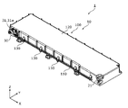
- FIG. 1 is a perspective view showing the appearance of a power storage device according to an embodiment.
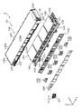
- FIG. 2 is an exploded perspective view showing components included in the power storage device according to the embodiment.
- FIG. 3 is an exploded perspective view showing components included in the power storage device according to the embodiment.
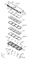
- FIG. 4 is an exploded perspective view showing each component by disassembling the electric storage element according to the embodiment.
- FIG. 5 is a perspective view showing the configuration of the busbar according to the embodiment.
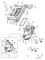
- 6A and 6B are a perspective view and a perspective cross-sectional view showing the configuration of the terminal unit and its periphery according to the embodiment.
- FIG. 7 is a cross-sectional view showing the configuration of the terminal unit and its surroundings according to the embodiment.
- a power storage device includes a power storage element, an exterior body that houses the power storage element and has a wall portion with a through hole formed therein, and a bus bar penetrating through the through hole.
- a through hole is formed at a position where the bus bar is to be arranged on the wall of the exterior body, and the bus bar passes through the through hole.
- the wall portion may be made of metal, and the power storage device may further include an insulating member having an insulating portion arranged inside the through hole and around the bus bar.
- a through hole is formed in a metal wall portion of an exterior body, a bus bar is passed through the through hole, and an insulating portion of an insulating member is arranged inside the through hole and around the bus bar. do. As a result, it is possible to improve the flexibility of the arrangement position of the busbar while improving the insulation between the wall portion of the exterior body and the busbar.
- the insulating member further has a protruding portion protruding from the insulating portion along the outer surface of the wall portion.
- An attachment member may be provided for attaching the projection to the wall.
- the mounting member for mounting the projecting portion of the insulating member to the wall portion from the outside of the wall portion is arranged outside the wall portion of the exterior body. Easy to install. As a result, it is possible to easily improve the insulation between the wall portion of the exterior body and the busbar, and to improve the degree of freedom in the arrangement position of the busbar.
- the mounting member may pass through the projection and be inserted into a recess formed on the outer surface of the wall to be fixed to the wall.
- the attachment member when the insulating member is attached to the wall portion of the exterior body by the attachment member, the attachment member is inserted into the recess formed in the outer surface of the wall portion instead of penetrating the wall portion. Affix to the wall. As a result, a through hole through which the attachment member penetrates is not formed in the wall portion of the exterior body, so that the sealing performance of the exterior body can be improved.
- a gasket may be provided between the wall portion and the projecting portion, and the gasket may be provided between the mounting member and the through hole.
- the sealing performance of the exterior body by the insulating member (the sealing performance of the through-hole of the wall portion by the insulating member) is improved.
- the gasket between the mounting member and the through-hole of the wall the through-hole can be sealed by the gasket near the through-hole. (sealability of through holes) can be further improved.
- the wall portion may be a side wall of the exterior body, and the attachment member may attach the projecting portion to the side wall.
- the longitudinal direction of the power storage device the direction in which the power storage unit and the control unit are arranged, the direction in which the short sides of the container of the power storage element face each other, or the direction in which the pair of electrode terminals of the power storage element are arranged is Define the X-axis direction.
- the lateral direction of the power storage device, the alignment direction of the power storage element, the busbar plate, the busbar, and the busbar cover, the alignment direction of the body and lid of the container of the power storage element, or the projecting direction of the electrode terminal of the power storage element is the Y-axis direction.
- the direction in which the main body and the lid of the power storage device are arranged, the direction in which the power storage element and the spacer are arranged, the direction in which the long sides of the container of the power storage element face each other, the stacking direction of the electrode plates of the electrode body of the power storage element, or the vertical direction is defined as the Z-axis direction.
- These X-axis direction, Y-axis direction, and Z-axis direction are directions that cross each other (perpendicularly in this embodiment).
- the Z-axis direction may not be the vertical direction, but for convenience of explanation, the Z-axis direction will be described below as the vertical direction.
- the positive direction of the X-axis indicates the direction of the arrow on the X-axis
- the negative direction of the X-axis indicates the direction opposite to the positive direction of the X-axis.
- Expressions indicating relative directions or orientations, such as parallel and orthogonal, also include cases where the directions or orientations are not strictly speaking.
- “Two directions are parallel” means not only that the two directions are completely parallel, but also that they are substantially parallel, that is, including a difference of, for example, several percent. do.
- the expression “insulation” means "electrical insulation”.
- FIG. 1 is a perspective view showing the appearance of a power storage device 1 according to this embodiment.
- FIGS. 2 and 3 are exploded perspective views showing components of the power storage device 1 according to the present embodiment.
- FIG. 3 shows a further disassembled configuration of the exterior body 100, the storage element 200 and the spacer 300 shown in FIG.
- the power storage device 1 is a device that can charge electricity from the outside and discharge electricity to the outside, and has a substantially rectangular parallelepiped shape in the present embodiment.
- the power storage device 1 is a battery module (assembled battery) used for power storage, power supply, or the like.
- the power storage device 1 is used for driving mobile bodies such as automobiles, motorcycles, water crafts, ships, snowmobiles, agricultural machinery, construction machinery, or railway vehicles for electric railways, or for starting engines. Used as a battery or the like.
- the vehicles include electric vehicles (EV), hybrid electric vehicles (HEV), plug-in hybrid electric vehicles (PHEV), and fossil fuel (gasoline, light oil, liquefied natural gas, etc.) vehicles.
- Examples of railway vehicles for the electric railway include electric trains, monorails, linear motor cars, and hybrid trains having both diesel engines and electric motors.
- the power storage device 1 can also be used as a stationary battery or the like for home or business use.
- the power storage device 1 includes a power storage unit 10 and a control unit 20 , and the power storage unit 10 has an exterior body 100 and a terminal unit 30 .
- a portion of the power storage device 1 having the power storage element 200 is referred to as a power storage unit 10
- a portion having a control device for controlling the power storage element 200 is referred to as a control unit 20 .
- inside the exterior body 100 there are a storage element 200, a spacer 300 (a first spacer 310 and a second spacer 320), a bus bar plate 400, a bus bar 500 (510 to 530), a bus bar
- the cover 600, the control unit 20, and the like are accommodated.
- the power storage device 1 may include, in addition to the components described above, an exhaust section for discharging gas discharged from the power storage element 200 to the outside of the exterior body 100 .
- the terminal unit 30 is a member having an external terminal 31a that is a positive or negative module terminal (general terminal) of the power storage device 1. Attached to the negative end.
- the terminal unit 30 has a busbar 31 .
- the bus bar 31 is a plate-shaped conductive member, and is formed of a conductive member made of metal such as aluminum, aluminum alloy, copper, copper alloy, nickel, or a combination thereof, or a conductive member other than metal.
- the bus bar 31 is connected to the bus bar 520 at its positive Y-axis end and has a negative Y-axis end functioning as an external terminal 31a.
- the external terminal 31a is a negative external terminal.
- power storage element 200 of power storage unit 10 and external terminal 31 a are electrically connected via bus bar 520 .
- Bus bar 31 and bus bar 520 are connected (joined) by bolting, but may be connected (joined) by welding or the like. A detailed description of the configuration of the terminal unit 30 will be given later.
- the control unit 20 is a device that has a control device (not shown) that controls the power storage elements 200 that the power storage unit 10 has. Specifically, it is a BMS (Battery Management System) that controls the power storage elements 200.
- the control device includes a circuit board, a fuse, a relay, a semiconductor switch such as a FET (Field Effect Transistor), a shunt resistor, and the like, which control charging and discharging of the storage element 200 .
- An external terminal 21 that is a positive or negative module terminal (general terminal) of the power storage device 1 is arranged at the end of the exterior body 100 in the positive direction of the X axis and the negative direction of the Y axis.
- the external terminal 21 is a terminal with a polarity different from that of the external terminal 31 a of the terminal unit 30 (positive external terminal).
- External terminal 21 is electrically connected to storage element 200 .
- the power storage device 1 charges electricity from the outside and discharges electricity to the outside through these external terminals 21 and 31a.
- the external terminals 21 are made of any conductive material or the like that can be used for the busbars 31 .
- the exterior body 100 is a box-shaped (substantially rectangular parallelepiped) container (module case) that constitutes the housing (outer shell) of the power storage device 1 (power storage unit 10).
- the exterior body 100 is arranged outside the power storage elements 200 and the like, fixes the power storage elements 200 and the like at predetermined positions, and protects them from impacts and the like.
- the exterior body 100 includes a first exterior body 110 and a second exterior body 120 arranged side by side in the Z-axis direction, joining members 130 and 140 for joining the first exterior body 110 and the second exterior body 120, and a collar. 150 and .
- the first exterior body 110 is arranged in the Z-axis minus direction of the second exterior body 120 and is a flat rectangular member that constitutes the bottom wall of the exterior body 100, on which the power storage element 200 and the like are placed.
- the second exterior body 120 is a bottomed rectangular tubular member that constitutes the main body of the exterior body 100 (a portion other than the bottom wall), and is connected (joined) to the first exterior body 110 to cover the power storage element 200 and the like.
- the second exterior body 120 has a top wall 120a, a pair of long side walls 120b, and a pair of short side walls 120c.
- the second exterior body 120 has an opening facing in the negative direction of the Z axis, and the first exterior body 110 functions as a lid that closes the opening of the second exterior body 120 .
- the first exterior body 110 and the second exterior body 120 are made of metal members such as stainless steel, aluminum, aluminum alloy, iron, steel plate, etc., or insulation treatment such as insulation coating, from the viewpoint of ensuring safety (breakage resistance). It is formed of a highly rigid member such as the metal member to which the The first exterior body 110 and the second exterior body 120 can be formed by, for example, aluminum die casting.
- the first exterior body 110 and the second exterior body 120 may be formed of members of the same material, or may be formed of members of different materials.
- connection portions 111 and 112 of the first exterior body 110 and the connection portion 121 and the like of the second exterior body 120 are joined using the joining members 130 and 140 and the collar 150 to form the first
- the exterior body 110 and the second exterior body 120 are connected (fixed).
- the long side wall 120b which is the wall portion (side wall) of the second exterior body 120 in the Y-axis negative direction, is positioned to sandwich the busbar plate 400, the busbars 500 (510 to 530), and the busbar cover 600 with the power storage element 200. placed.
- a through hole 125 is formed in the long side wall 120b.
- the through-hole 125 is a through-hole having a rectangular shape when viewed from the Y-axis direction, which is arranged at the end of the long side wall 120b in the negative direction of the X-axis and penetrates the long side wall 120b in the Y-axis direction.
- the through hole 125 is a through hole through which the bus bar 31 passes when connecting (joining) the bus bar 31 of the terminal unit 30 to the bus bar 520 .
- the first exterior body 110 and the second exterior body 120 are joined together to sandwich the power storage element 200 therebetween.
- the first exterior body 110 and the second exterior body 120 sandwich and constrain the power storage element 200 in the Z-axis direction, and apply a restraining force to the power storage element 200 in the Z-axis direction.
- the first exterior body 110 and the second exterior body 120 include a plurality of power storage elements 200 arranged in the X-axis direction and the Z-axis direction, and a plurality of spacers 300 (a first spacer 310 and a second spacer 300) arranged in the Z-axis direction.
- first exterior body 110 and the second exterior body 120 collectively sandwich and constrain the plurality of power storage elements 200 and the plurality of spacers 300 .
- first exterior body 110 and the second exterior body 120 are a pair of end plates.
- the storage element 200 is a secondary battery (single battery) capable of charging and discharging electricity, and more specifically, a non-aqueous electrolyte secondary battery such as a lithium ion secondary battery. .
- the power storage element 200 has a flattened rectangular parallelepiped shape (rectangular shape), a plurality of power storage elements 200 are arranged in the X-axis direction, and a plurality of power storage elements 200 are stacked in the Z-axis direction.
- the eight power storage elements 200 are placed horizontally (sideways) (with the long side surfaces 211a of the power storage elements 200, which will be described later, facing the Z-axis direction).
- four power storage elements 201 to 204 are arranged side by side in the X-axis direction from the X-axis minus direction to the X-axis plus direction, and four power storage elements 205 to 208 are arranged from the X-axis minus direction to the X-axis plus direction. are arranged side by side in the X-axis direction.
- Four power storage elements 201 to 204 and four power storage elements 205 to 208 are stacked (stacked flat) in the Z-axis direction.
- the number of power storage elements 200 is not particularly limited, and any number of power storage elements 200 may be arranged (arranged) in the X-axis direction, and how many power storage elements 200 may be arranged (stacked) in the Z-axis direction.
- the shape of the electric storage element 200 is not limited to the rectangular shape described above, and may be other shapes such as a polygonal columnar shape, a cylindrical shape, an elliptical columnar shape, and an oval columnar shape.
- the storage element 200 is not limited to a non-aqueous electrolyte secondary battery, and may be a secondary battery other than a non-aqueous electrolyte secondary battery, or may be a capacitor.
- the power storage element 200 may be a primary battery that can use stored electricity without being charged by the user, instead of a secondary battery.
- the storage element 200 may be a battery using a solid electrolyte.
- the storage element 200 may be a pouch-type storage element. A detailed description of the configuration of the storage element 200 will be given later.
- the spacer 300 is a rectangular plate-shaped spacer that is aligned with the power storage element 200 in the Z-axis direction and is arranged adjacent to the power storage element 200 .
- Spacer 300 is arranged in the positive Z-axis direction or the negative Z-axis direction of storage element 200 , facing long side surface 211 a of storage element 200 .
- the spacer 300 is made of polycarbonate (PC), polypropylene (PP), polyethylene (PE), polystyrene (PS), polyphenylene sulfide resin (PPS), polyphenylene ether (PPE (including modified PPE)), polyethylene terephthalate (PET), Polybutylene terephthalate (PBT), polyetheretherketone (PEEK), tetrafluoroethylene/perfluoroalkyl vinyl ether (PFA), polytetrafluoroethylene (PTFE), polyethersulfone (PES), polyamide (PA), ABS resin
- PC polycarbonate
- PP polypropylene
- PE polyethylene
- PS polystyrene
- PPS polyphenylene sulfide resin
- PPE polyphenylene ether
- PET polyethylene terephthalate
- PBT Polybutylene terephthalate
- PEEK polyetheretherketone
- PTFE polytetrafluoroethylene
- PTFE poly
- a first spacer 310 and a pair of second spacers 320 are arranged as spacers 300 .
- the first spacer 310 is arranged across the plurality of power storage elements 200 at a position adjacent to the plurality of power storage elements 200 arranged in the X-axis direction in the Z-axis direction.
- the first spacer 310 is positioned adjacent to the four power storage elements 200 (201 to 204 or 205 to 208) aligned in the X-axis direction in the Z-axis direction, and extends across the four power storage elements 200 in the X-axis direction. It is arranged so as to extend in the axial direction.
- the first spacer 310 is an intermediate spacer arranged between the energy storage elements 200 adjacent in the Z-axis direction (between the four energy storage elements 201 to 204 and the four energy storage elements 205 to 208). is.
- the second spacer 320 is arranged across the plurality of power storage elements 200 arranged in the X-axis direction at a position sandwiching the plurality of power storage elements 200 with the first spacer 310 in the Z-axis direction. Specifically, the second spacer 320 and the first spacer 310 sandwich the four energy storage elements 200 (201 to 204 or 205 to 208) aligned in the X-axis direction in the Z-axis direction. 200 extending in the X-axis direction.
- second spacer 320 is an end spacer arranged between power storage element 200 and first exterior body 110 or second exterior body 120 . Specifically, a pair of second spacers 320 are arranged between the four storage elements 205 to 208 and the first exterior body 110 and between the four storage elements 201 to 204 and the second exterior body 120. be done.
- first spacer 310 and the pair of second spacers 320 are arranged so as to sandwich the power storage element 200 in the Z-axis direction, and are spaced between the power storage elements 200 and between the power storage element 200 and the first exterior body 110 . and the second exterior body 120 are insulated.
- the busbar plate 400 is a flat rectangular insulating member that is placed between the power storage element 200 and the busbar 500 and that can insulate the busbar 500 from other members and regulate the position of the busbar 500 .
- the busbar plate 400 is made of any insulating resin material or the like that can be used for the spacers 300 .
- the busbar plate 400 is arranged in the Y-axis negative direction of the plurality of power storage elements 200 and positioned with respect to the plurality of power storage elements 200 . As a result, the bus bar 500 is positioned with respect to the plurality of power storage elements 200 and joined to electrode terminals 220 (described later) of the plurality of power storage elements 200 .
- the bus bar 500 is a plate-shaped member that is arranged in the Y-axis negative direction of the plurality of storage elements 200 and is connected (bonded) to the plurality of storage elements 200 and the terminal unit 30 .
- three busbars 510 , 520 and 530 are arranged as busbars 500 .
- Bus bar 510 is arranged between bus bar 520 and bus bar 530 and connects electrode terminals 220 of adjacent power storage elements 200 to each other.
- the bus bar 520 is arranged most in the negative direction of the X axis among the plurality of bus bars 500, and connects the electrode terminal 220 of the power storage element 200, which is the most in the negative direction of the X axis, to the bus bar 31 of the terminal unit 30 to connect the power storage element. 200 and the external terminal 31a are electrically connected.
- Bus bar 530 is arranged most in the positive X-axis direction among a plurality of bus bars 500 and electrically connects electrode terminal 220 of storage element 200 in the most positive X-axis direction with external terminal 21 .
- bus bar 500 and electrode terminal 220 of power storage element 200 are connected (joined) by welding, but may be connected (joined) by bolting or the like.
- Bus bar 500 is formed of any conductive material or the like that can be used for bus bar 31 .
- bus bar 500 connects two storage elements 200 in parallel to form four sets of storage element groups, and connects the four sets of storage element groups in series. The form is not particularly limited. A detailed description of the configuration of bus bar 500 will be given later.
- the busbar cover 600 is an insulating cover member that is arranged to cover the busbar 500 and insulates the busbar 500 from other members.
- the busbar cover 600 is a plate-shaped member that extends in the X-axis direction over the plurality of busbars 500 (510 to 530) so as to cover the plurality of busbars 500 (510 to 530).
- the busbar cover 600 is arranged between the busbar 500 and the wall portion of the second exterior body 120 (the long side wall 120b in the negative Y-axis direction). Thereby, the busbar cover 600 insulates the plurality of busbars 500 from other members such as the long side walls 120b.
- the busbar cover 600 is made of any insulating resin material or the like that can be used for the spacers 300 .
- Busbar cover 600 is arranged at a position sandwiching busbar 500 with busbar plate 400 , and has a portion that engages with busbar plate 400 , so that busbar cover 600 is attached and fixed to busbar plate 400 .
- FIG. 4 is an exploded perspective view showing each component by disassembling the power storage device 200 according to the present embodiment. Specifically, FIG. 4 shows an exploded view of each part in a state in which the electric storage device 200 shown in FIG. 3 is placed vertically (upright).
- the electric storage element 200 includes a container 210, a pair of (positive electrode and negative electrode) electrode terminals 220, and a pair of (positive electrode and negative electrode) gaskets 230.
- a pair of (positive electrode and negative electrode) gaskets 240 , a pair (positive electrode and negative electrode) current collectors 250 , and an electrode body 260 are housed inside the container 210 .
- An electrolytic solution non-aqueous electrolyte
- the type thereof is not particularly limited as long as it does not impair the performance of the electric storage element 200, and various kinds can be selected.
- a spacer disposed on the side or below the electrode body 260, an insulating film wrapping the electrode body 260 and the like, an insulating sheet covering the outer surface of the container 210, or the like may be disposed.
- the container 210 is a rectangular parallelepiped (square or box-shaped) case having a container body 211 with an opening and a container lid 212 that closes the opening of the container body 211 .
- the container 210 has a structure that can seal the inside by joining the container main body 211 and the container lid 212 by welding or the like after the electrode body 260 and the like are accommodated inside the container main body 211 .
- the material of the container body 211 and the container lid 212 is not particularly limited, but weldable metals such as stainless steel, aluminum, aluminum alloy, iron, and plated steel plate are preferable.
- the container main body 211 is a rectangular tubular member that constitutes the main body of the container 210 and has a bottom, and an opening is formed on the Y-axis negative direction side.
- the container body 211 has a pair of rectangular and planar (flat) long side surfaces 211a on both side surfaces in the Z-axis direction, and a pair of rectangular and planar (flat) side surfaces on both side surfaces in the X-axis direction. It has a short side surface 211b and a rectangular planar (flat) bottom surface 211c on the Y-axis plus direction side.
- the container lid 212 is a rectangular plate-like member that constitutes the lid of the container 210 , and is arranged to extend in the X-axis direction in the negative Y-axis direction of the container body 211 .
- the container cover 212 has a gas discharge valve 212a that releases the pressure inside the container 210 when the pressure rises, and an injection part (not shown) for injecting the electrolytic solution into the container 210. ) etc. are provided.
- the electrode body 260 is a power storage element (power generation element) formed by laminating a positive electrode plate, a negative electrode plate, and a separator.
- the positive electrode plate is formed by forming a positive electrode active material layer on a positive electrode substrate layer, which is a collector foil made of a metal such as aluminum or an aluminum alloy.
- the negative electrode plate is formed by forming a negative electrode active material layer on a negative electrode substrate layer, which is a collector foil made of a metal such as copper or a copper alloy.
- the active material used for the positive electrode active material layer and the negative electrode active material layer any known material can be appropriately used as long as it can intercalate and deintercalate lithium ions.
- electrode body 260 is formed by winding electrode plates (positive electrode plate and negative electrode plate) around a winding axis (virtual axis parallel to the X-axis direction) extending in the X-axis direction. It is a type (so-called vertically wound type) electrode body.
- the Z-axis direction is also called the stacking direction.
- the electrode body 260 is formed by stacking electrode plates in the stacking direction.
- the electrode body 260 has a pair of flat portions 261 aligned in the Z-axis direction and a pair of curved portions 262 aligned in the Y-axis direction by winding the electrode plate. is the stacking direction of the electrode plates in the flat portion 261 .
- the flat portion 261 is a flat portion that connects the ends of the pair of curved portions 262, and the curved portion 262 is a portion curved in a semicircular shape or the like so as to protrude in the Y-axis direction.
- the direction in which the flat surface of the flat portion 261 faces or the facing direction of the pair of flat portions 261 can also be defined as the stacking direction. Therefore, it can be said that the power storage elements 201 and 205 are arranged in the stacking direction. The same applies to other storage elements 200 .
- the X-axis direction in which the power storage elements 201 to 204 are arranged is also called an arrangement direction.
- the power storage elements 201 to 204 are arranged in an arrangement direction crossing the stacking direction. The same applies to the storage elements 205-208.
- the active material is formed (coated) at the ends of the positive electrode plate and the negative electrode plate in the shifted direction. 3) It has a part (active material layer non-formed part) where the base material layer is exposed without being exposed.
- the electrode assembly 260 protrudes from the flat portion 261 and the curved portion 262 to both sides in the X-axis direction at both ends in the X-axis direction, and the current collector 250 is formed by laminating the active material layer-free portions of the positive electrode plate and the negative electrode plate. It has an end 263 connected to the .
- the electrode body 260 may be a so-called horizontal-wound electrode body formed by winding electrode plates around a winding axis extending in the Y-axis direction, or a laminated type electrode body formed by stacking a plurality of flat plate-shaped electrode plates ( Any type of electrode body may be used, such as a stack type electrode body or a bellows-shaped electrode body in which electrode plates are folded into a bellows shape.
- the flat portion is the flat portion other than the curved portion and the connection portion (tab) with the current collector.
- a flat portion is a flat portion other than the connection portion (tab) with the current collector.
- the electrode terminal 220 is a terminal member (a positive terminal and a negative terminal) of the storage element 200, and is arranged on the container lid 212 so as to protrude in the Y-axis negative direction.
- the electrode terminal 220 is electrically connected to the positive plate and the negative plate of the electrode assembly 260 via the current collector 250 .
- the electrode terminal 220 is made of a conductive member such as metal such as aluminum, aluminum alloy, copper, or copper alloy.
- the current collector 250 is a conductive member (a positive electrode current collector and a negative electrode current collector) electrically connected to the electrode terminal 220 and the end portion 263 of the electrode body 260 .
- the current collector 250 is made of aluminum, an aluminum alloy, copper, a copper alloy, or the like.
- the gaskets 230 and 240 are flat insulating sealing members arranged between the container lid 212 and the electrode terminal 220 and current collector 250 . Gaskets 230 and 240 are made of any insulating resin material or the like that can be used for spacer 300 .
- FIG. 5 is a perspective view showing the configuration of busbar 500 according to the present embodiment. Specifically, FIG. 5 shows a bus bar 510 and a bus bar 520 in the negative direction of the X axis among the bus bars 500, and the storage elements 200 (201, 202, 205 and 206) to which the bus bars 510 and 520 are connected. ing. Three busbars 510 of busbars 500 have the same configuration, and busbars 520 and 530 have the same configuration, so in FIG. .
- the bus bar 510 has a connecting portion 511, a connecting portion 512, a connecting portion 513, a connecting portion 514, a connecting portion 515, a connecting portion 516, and a connecting portion 517.
- the busbar 520 has a connection portion 521 , a connection portion 522 , a connection portion 523 , and a connecting portion 524 .
- the connecting portion 511 is a plate-like and rectangular portion parallel to the XZ plane, which is connected (joined) to the electrode terminal 223 of the power storage element 201 in the positive direction of the X-axis.
- the electrode terminal 223 is a positive electrode terminal (positive electrode terminal).
- the connection portion 512 is a plate-like rectangular portion parallel to the XZ plane, which is arranged in the Z-axis negative direction of the connection portion 511 and is connected (joined) to the electrode terminal 224 of the power storage element 205 in the X-axis positive direction. is.
- the electrode terminal 224 is a positive electrode terminal (positive electrode terminal).
- the connecting portion 513 is a plate-like rectangular portion parallel to the XZ plane, which is arranged in the positive direction of the X-axis of the connecting portion 511 and is connected (joined) to the electrode terminal 225 of the power storage element 202 in the negative direction of the X-axis. is.
- the electrode terminal 225 is a negative electrode terminal (negative terminal).
- the connection portion 514 is a plate-like rectangular portion parallel to the XZ plane, which is arranged in the negative Z-axis direction of the connection portion 513 and is connected (joined) to the electrode terminal 226 of the power storage element 206 in the negative X-axis direction. is.
- the electrode terminal 226 is a negative electrode terminal (negative terminal).
- the connecting portion 515 is a substantially C-shaped protruding portion that protrudes in the negative Y-axis direction from the edge of the connecting portion 511 in the positive direction of the X-axis and the edge of the connecting portion 513 in the negative direction of the X-axis. is.
- the connecting portion 516 is a substantially C-shaped protruding portion when viewed from the Z-axis direction, protruding in the negative Y-axis direction from the edge of the connecting portion 512 in the positive direction of the X-axis and the edge of the connecting portion 514 in the negative direction of the X-axis. is.
- the connecting portion 517 is a substantially C-shaped concave portion that is recessed in the positive Y-axis direction from the edge of the connecting portion 515 in the negative Z-axis direction and the edge of the connecting portion 516 in the positive Z-axis direction.
- the connecting portion 515 connects the connecting portions 511 and 513
- the connecting portion 516 connects the connecting portions 512 and 514
- the connecting portion 517 connects the connecting portions 515 and 516 .
- the connecting portion 521 is a plate-like and rectangular portion parallel to the XZ plane, which is connected (joined) to the electrode terminal 221 of the power storage element 201 in the negative direction of the X-axis.
- the electrode terminal 221 is a negative electrode terminal (negative terminal).
- the connecting portion 522 is a flat plate-like rectangular portion parallel to the XZ plane, which is arranged in the negative Z-axis direction of the connecting portion 521 and is connected (joined) to the electrode terminal 222 of the power storage element 205 in the negative X-axis direction. is.
- the electrode terminal 221 is a negative electrode terminal (negative terminal).
- the connecting portion 523 is a plate-like and rectangular portion parallel to the XY plane that protrudes in the negative Y-axis direction from the edge in the positive Z-axis direction of the portion of the connecting portion 522 in the negative X-axis direction.
- the connection portion 523 is connected (joined) to the external terminal 31 a of the bus bar 31 of the terminal unit 30 .
- the connecting portion 524 extends along the Y-axis from the edge of the connecting portion 521 in the positive direction of the X-axis in the negative direction of the Z-axis and the edge of the end of the connecting portion 522 in the positive direction of the X-axis in the positive direction of the Z-axis. It is a substantially C-shaped protruding portion protruding in the negative direction when viewed from the X-axis direction. Thereby, the connecting portion 524 connects the connecting portions 521 and 522 .
- FIG. 6A and 6B are a perspective view and a perspective cross-sectional view showing the configuration of the terminal unit 30 and its surroundings according to the present embodiment.
- (a) of FIG. 6 is a perspective view showing the terminal unit 30, the through hole 125 formed in the long side wall 120b of the second exterior body 120 of the exterior body 100, and the configuration of the periphery thereof.
- FIG. 6(b) is a perspective cross-sectional view showing the configuration of the terminal unit 30 shown in FIG. 6(a) cut along a plane passing through the center of the terminal unit 30 and parallel to the YZ plane.
- FIG. 7 is a sectional view showing the configuration of the terminal unit 30 and its surroundings according to the present embodiment. Specifically, FIG. 7 shows a cross section when the end of the power storage unit 10 in the negative direction of the X axis is cut along a plane that passes through the center of the terminal unit 30 and is parallel to the YZ plane.
- the terminal unit 30 includes an insulating member 32, a terminal connection portion 33, a busbar connection portion 34, a mounting member 35, and a bus bar 31 having the external terminals 31a. have.
- a groove portion 127 , four concave portions 128 , and a restricting portion 129 are provided at positions corresponding to the terminal units 30 on the long side wall 120 b of the second exterior body 120 .
- a gasket 160 is arranged between the terminal unit 30 and the long side wall 120b.
- the insulating member 32 is an insulating member that covers the busbar 31 and insulates the busbar 31 from other members.
- the insulating member 32 is inserted into the through hole 125 of the long side wall 120b of the second exterior body 120, and is attached to the long side wall 120b in a state of protruding outward (Y-axis negative direction) from the through hole 125.
- the insulating member 32 is made of any insulating resin material or the like that can be used for the spacer 300 .
- the insulating member 32 is integrated (integrally formed) with the busbar 31, the terminal connection portion 33, the busbar connection portion 34, and the mounting member 35 by insert molding.
- the insulating member 32 has an insulating portion 32a, a first insulating projecting portion 32b, a second insulating projecting portion 32c, and a terminal block 32e.
- the insulating portion 32 a is a portion arranged inside the through hole 125 and around the bus bar 31 .
- the inner side of the through-hole 125 is a portion toward the center of the annular peripheral wall (the inner circumference or the inner edge of the through-hole 125) forming the through-hole 125, and is the inner circumference of the through-hole 125 when viewed from the Y-axis direction. the inner part.
- the insulating portion 32a is disposed inside the through-hole 125 and around the busbar 31 over the entire circumference in the X-axis direction and the Z-axis direction at the center portion of the busbar 31 in the Y-axis direction. It is an annular portion when viewed from the axial direction.
- the insulating portion 32 a is arranged between the peripheral wall of the through hole 125 and the bus bar 31 .
- the insulating portion 32 a ensures insulation between the long side wall 120 b and the bus bar 31 .
- the first insulating projecting portion 32b is a projecting portion that projects from the insulating portion 32a along the busbar 31 in the positive Y-axis direction. It covers both side surfaces in the X-axis direction and the end surface in the plus direction of the Y-axis. Inside the second exterior body 120 , the surface of the busbar 31 in the negative Z-axis direction is exposed from the insulating member 32 , and this exposed portion is connected to the busbar 520 .
- a busbar connecting portion 34 for connecting the busbar 31 and the busbar 520 is arranged on the first insulating projecting portion 32b.
- the busbar connection portion 34 is a joint member that is joined to the joint member 34a to connect the busbar 31 and the busbar 520.
- the busbar connecting portion 34 is a nut having a female thread
- the joining member 34a is a bolt having a male thread.
- the joint member 34a is inserted into the through hole formed in the connection portion 523 of the busbar 520, and the male screw portion of the joint member 34a is screwed into the female screw portion of the busbar connection portion 34, whereby the joint member 34a is connected to the busbar. It is fixed to the part 34 . Thereby, the bus bar 31 and the bus bar 520 are connected (bonded).
- the second insulating projecting portion 32c is a projecting portion that projects from the insulating portion 32a along the outer surface of the long side wall 120b (wall portion). Specifically, the second insulating projecting portion 32c protrudes from the insulating portion 32a to both sides in the X-axis direction and both sides in the Z-axis direction on the outside of the second exterior body 120, and is attached to the long side wall 120b. More specifically, four circular through-holes 32d are formed in the Y-axis direction at both ends in the X-axis direction and both ends in the Z-axis direction of the second insulating projecting portion 32c. ing. By inserting the mounting member 35 into the four through holes 32d and fixing the mounting member 35 to the concave portion 128 of the long side wall 120b, the second insulating projecting portion 32c is mounted to the long side wall 120b.
- the mounting member 35 is arranged outside (Y-axis minus direction) of the long side wall 120b (wall portion), and the second insulating projecting portion 32c (protruding part) to the long side wall 120b (wall part).
- the mounting member 35 penetrates through the through hole 32d of the second insulating projecting portion 32c (projecting portion) and is inserted into the recess 128 formed in the outer surface of the long side wall 120b (wall portion) to form the long side wall 120b (wall portion). part).
- the recessed portion 128 is a circular recessed portion when viewed from the Y-axis direction, in which the outer surface (the surface in the Y-axis negative direction) of the long side wall 120b is recessed in the Y-axis positive direction.
- the mounting member 35 is a screw (bolt) having a male threaded portion, and the recess 128 has a female threaded portion.
- the mounting member 35 is fixed to the recess 128 by screwing it onto the threaded portion. Thereby, the mounting member 35 mounts the second insulating projecting portion 32c (projecting portion) to the long side wall 120b (side wall).
- a gasket 160 is arranged between the long side wall 120b (wall portion) and the second insulating projecting portion 32c (projecting portion). Specifically, a groove portion 127 is formed around the through-hole 125 in the long side wall 120 b , and the gasket 160 is arranged in the groove portion 127 .
- the groove portion 127 is an annular groove portion (recess) viewed from the Y-axis direction, in which the outer surface of the long side wall 120b (the surface in the negative direction of the Y-axis) is recessed in the positive direction of the Y-axis over the entire periphery of the through-hole 125. is. Groove 127 is located closer to through-hole 125 than recess 128 . Groove 127 is arranged between recess 128 and through hole 125 . Therefore, the gasket 160 is arranged between the mounting member 35 and the through hole 125 .
- the gasket 160 is an annular O-ring when viewed from the Y-axis direction, and is arranged inside the groove 127 over the entire length of the groove 127 .
- a gasket 160 is placed in compression between the long side wall 120b and the second insulating protrusion 32c.
- the gasket 160 is made of rubber (natural rubber, synthetic rubber), any insulating resin material that can be used for the spacer 300, or the like.
- a restricting portion 129 is provided to restrict the movement of the second insulating projecting portion 32c (terminal unit 30) in the positive Z-axis direction.
- the restricting portion 129 protrudes in the negative Y-axis direction from the outer surface of the long side wall 120b, which is arranged in the positive Z-axis direction of the second insulating protrusion 32c when the second insulating protrusion 32c is attached to the long side wall 120b. It is a protrusion.
- the terminal block 32e is a portion that protrudes from the insulating portion 32a along the busbar 31 in the negative Y-axis direction. Both side surfaces and the end surface in the Y-axis negative direction are covered. Outside the second exterior body 120, the surface of the bus bar 31 in the Z-axis positive direction is exposed from the insulating member 32, and this exposed portion functions as an external terminal 31a.
- the terminal block 32e is a pedestal portion that supports the external terminal 31a outside the second exterior body 120. As shown in FIG. A terminal connection portion 33 is arranged on the terminal block 32e.
- the terminal connection portion 33 is a portion for connecting an external conductive member to the external terminal 31a.
- the terminal connecting portion 33 is a bolt having a male screw portion, is inserted into a through hole formed in the external terminal 31a from the Z-axis negative direction, and is inserted from the external terminal 31a in the Z-axis positive direction. placed in a protruding state.
- An end portion (bolt head) of the terminal connection portion 33 in the negative Z-axis direction is embedded in the terminal block 32e.
- the through hole 125 is formed in the wall portion (long side wall 120b) of the exterior body 100 at the position where the bus bar 31 of the terminal unit 30 is desired to be arranged.
- the through hole 125 is configured so that the bus bar 31 passes through it.
- the busbar 31 can be arranged at a desired position, so that the degree of freedom of the arrangement position of the busbar 31 can be improved.
- the long side wall 120b in which the through hole 125 is formed is made of metal, the long side wall 120b and the bus bar 31 may be electrically connected. For this reason, a through hole 125 is formed in the metal long side wall 120 b of the exterior body 100 , the bus bar 31 is passed through the through hole 125 , and an insulating member is provided inside the through hole 125 and around the bus bar 31 in the terminal unit 30 . 32 insulating portions 32a are arranged. As a result, the insulation between the wall portion (long side wall 120b) of the exterior body 100 and the busbars 31 can be improved, and the degree of freedom in the arrangement position of the busbars 31 can be improved.
- a mounting member 35 is arranged outside the long side wall 120b of the exterior body 100 to mount the second insulating projecting portion 32c (projecting portion) of the insulating member 32 of the terminal unit 30 to the long side wall 120b from the outside of the long side wall 120b. be. Accordingly, the insulating member 32 can be easily attached to the long side wall 120b by the attachment member 35. As shown in FIG. Therefore, it is possible to easily improve the insulation between the walls (long side walls 120b) of the exterior body 100 and the busbars 31, and to improve the degree of freedom in the arrangement position of the busbars 31.
- the mounting member 35 is formed on the outer surface of the long side wall 120b instead of penetrating the long side wall 120b. and is fixed to the long side wall 120b.
- a through hole through which the attachment member 35 penetrates is not formed in the wall portion (long side wall 120b) of the exterior body 100, so that the sealing performance of the exterior body 100 can be improved.
- the sealability of the exterior body 100 by the insulation member 32 is improved. sealing of the through-hole 125 of the side wall 120b) can be improved.
- the through hole 125 can be sealed by the gasket 160 near the through hole 125.
- the sealing property of the exterior body 100 by the insulating member 32 (sealing property of the through hole 125 of the long side wall 120b by the insulating member 32) can be further improved.
- the insulation member 32 By attaching the second insulating projecting portion 32c of the insulating member 32 of the terminal unit 30 to the long side wall 120b, which is the side wall of the exterior body 100, the insulation member 32 can be prevented from protruding in the height direction of the exterior body 100. Thereby, it is possible to prevent the height of the power storage device 1 from increasing.
- the second exterior body 120 of the exterior body 100 is a bottomed rectangular tubular member having an opening formed in the negative direction of the Z axis
- the first exterior body 110 is the second exterior body.
- 120 is a flat rectangular member that closes the opening.
- the first exterior body 110 is a bottomed rectangular cylindrical member with an opening formed in the positive direction of the Z axis
- the second exterior body 120 is a flat rectangular shape that closes the opening of the first exterior body 110 . It may be a shaped lid or any other shape.
- the second exterior body 120 is entirely made of metal.
- the long side wall 120b in which the through hole 125 is formed may also be made of an insulating member such as resin instead of metal. That is, the second exterior body 120 may be an insulating member such as resin as a whole.
- the long side wall 120 b or the second exterior body 120 can be made of any insulating resin material or the like that can be used for the spacer 300 .
- insulating portion 32 a (insulating member 32 ) may not be arranged inside through hole 125 and around bus bar 31 .
- the insulating portion 32a of the insulating member 32 is arranged along the entire circumference of the busbar 31. It may be a configuration that does not
- the mounting member 35 is inserted into the recess 128 formed on the outer surface of the long side wall 120b and fixed to the long side wall 120b.
- the mounting member 35 may be inserted into a concave portion formed in the inner surface of the long side wall 120b and fixed to the long side wall 120b, or may be inserted into a through hole formed in the long side wall 120b and attached to the long side wall 120b. may be fixed to
- the terminal unit 30 is attached to the long side wall 120b from the outside of the long side wall 120b by the mounting member 35 at the second insulating projecting portion 32c of the insulating member 32 .
- the terminal unit 30 may be attached to the long side wall 120b by fitting, engagement, crimping, welding (welding), or the like, without using the attachment member 35 .
- the terminal unit 30 may be attached to the long side wall 120b from the inside of the long side wall 120b.
- the gasket 160 is arranged closer to the through-hole 125 than the mounting member 35 (between the mounting member 35 and the through-hole 125). It may be arranged at a distant position. Alternatively, the configuration may be such that the gasket 160 is not arranged.
- the long side wall 120b of the second exterior body 120 is the wall portion in which the through hole 125 through which the busbar 31 penetrates is formed.
- the through hole 125 may be formed in any wall portion of the exterior body 100, such as the upper wall 120a of the second exterior body 120, the short side wall 120c, the first exterior body 110, or the like.
- the power storage device 1 does not need to include all the components described above. Power storage device 1 may not include control unit 20, spacer 300, busbar plate 400, busbar cover 600, or the like.
- the present invention can be realized not only as the power storage device 1, but also as a combination of the exterior body 100 and the busbar 31, or a combination of the exterior body 100 and the terminal unit 30 (the busbar 31 and the insulating member 32).
- the present invention can be applied to a power storage device having a power storage element such as a lithium ion secondary battery.
Abstract
Priority Applications (3)
| Application Number | Priority Date | Filing Date | Title |
|---|---|---|---|
| JP2023525714A JPWO2022255100A1 (fr) | 2021-06-04 | 2022-05-18 | |
| EP22815852.3A EP4350865A1 (fr) | 2021-06-04 | 2022-05-18 | Dispositif de stockage d'énergie |
| CN202280038212.1A CN117397104A (zh) | 2021-06-04 | 2022-05-18 | 蓄电装置 |
Applications Claiming Priority (2)
| Application Number | Priority Date | Filing Date | Title |
|---|---|---|---|
| JP2021-094615 | 2021-06-04 | ||
| JP2021094615 | 2021-06-04 |
Publications (1)
| Publication Number | Publication Date |
|---|---|
| WO2022255100A1 true WO2022255100A1 (fr) | 2022-12-08 |
Family
ID=84323306
Family Applications (1)
| Application Number | Title | Priority Date | Filing Date |
|---|---|---|---|
| PCT/JP2022/020627 WO2022255100A1 (fr) | 2021-06-04 | 2022-05-18 | Dispositif de stockage d'énergie |
Country Status (4)
| Country | Link |
|---|---|
| EP (1) | EP4350865A1 (fr) |
| JP (1) | JPWO2022255100A1 (fr) |
| CN (1) | CN117397104A (fr) |
| WO (1) | WO2022255100A1 (fr) |
Cited By (1)
| Publication number | Priority date | Publication date | Assignee | Title |
|---|---|---|---|---|
| JP7455797B2 (ja) | 2021-12-21 | 2024-03-26 | プライムプラネットエナジー&ソリューションズ株式会社 | 電池モジュール |
Citations (4)
| Publication number | Priority date | Publication date | Assignee | Title |
|---|---|---|---|---|
| JP2014238937A (ja) * | 2013-06-06 | 2014-12-18 | 株式会社オートネットワーク技術研究所 | 蓄電モジュール |
| JP2015141765A (ja) * | 2014-01-27 | 2015-08-03 | ダイキョーニシカワ株式会社 | 電池モジュール |
| JP2016062695A (ja) * | 2014-09-16 | 2016-04-25 | 株式会社豊田自動織機 | 電池パック |
| WO2017169728A1 (fr) | 2016-03-30 | 2017-10-05 | 三洋電機株式会社 | Bloc-batterie |
-
2022
- 2022-05-18 EP EP22815852.3A patent/EP4350865A1/fr active Pending
- 2022-05-18 JP JP2023525714A patent/JPWO2022255100A1/ja active Pending
- 2022-05-18 WO PCT/JP2022/020627 patent/WO2022255100A1/fr active Application Filing
- 2022-05-18 CN CN202280038212.1A patent/CN117397104A/zh active Pending
Patent Citations (4)
| Publication number | Priority date | Publication date | Assignee | Title |
|---|---|---|---|---|
| JP2014238937A (ja) * | 2013-06-06 | 2014-12-18 | 株式会社オートネットワーク技術研究所 | 蓄電モジュール |
| JP2015141765A (ja) * | 2014-01-27 | 2015-08-03 | ダイキョーニシカワ株式会社 | 電池モジュール |
| JP2016062695A (ja) * | 2014-09-16 | 2016-04-25 | 株式会社豊田自動織機 | 電池パック |
| WO2017169728A1 (fr) | 2016-03-30 | 2017-10-05 | 三洋電機株式会社 | Bloc-batterie |
Cited By (1)
| Publication number | Priority date | Publication date | Assignee | Title |
|---|---|---|---|---|
| JP7455797B2 (ja) | 2021-12-21 | 2024-03-26 | プライムプラネットエナジー&ソリューションズ株式会社 | 電池モジュール |
Also Published As
| Publication number | Publication date |
|---|---|
| JPWO2022255100A1 (fr) | 2022-12-08 |
| CN117397104A (zh) | 2024-01-12 |
| EP4350865A1 (fr) | 2024-04-10 |
Similar Documents
| Publication | Publication Date | Title |
|---|---|---|
| WO2022255100A1 (fr) | Dispositif de stockage d'énergie | |
| JP7392662B2 (ja) | 蓄電装置 | |
| JP7427903B2 (ja) | 蓄電装置 | |
| WO2022254937A1 (fr) | Dispositif de stockage d'électricité | |
| JP2021111562A (ja) | 蓄電装置 | |
| WO2022255162A1 (fr) | Dispositif de stockage d'énergie | |
| WO2022255017A1 (fr) | Dispositif de stockage d'énergie | |
| WO2022255161A1 (fr) | Dispositif de stockage d'électricité | |
| WO2023013466A1 (fr) | Dispositif de stockage d'énergie | |
| JP2020155283A (ja) | 蓄電素子及び蓄電装置 | |
| WO2023032562A1 (fr) | Dispositif de stockage d'énergie | |
| WO2022196479A1 (fr) | Dispositif de stockage d'énergie | |
| JP2022186359A (ja) | 蓄電装置 | |
| WO2022254931A1 (fr) | Dispositif de stockage d'énergie | |
| WO2021145271A1 (fr) | Dispositif de stockage électrique | |
| WO2023199781A1 (fr) | Dispositif de stockage d'énergie | |
| WO2023176752A1 (fr) | Dispositif de stockage d'électricité et procédé de fabrication de dispositif de stockage d'électricité | |
| WO2024009930A1 (fr) | Dispositif d'accumulation d'énergie | |
| WO2021145272A1 (fr) | Dispositif de stockage d'énergie | |
| WO2022186136A1 (fr) | Dispositif de stockage d'énergie | |
| WO2022230428A1 (fr) | Dispositif de stockage d'énergie | |
| WO2022172941A1 (fr) | Dispositif de stockage d'électricité | |
| WO2023068029A1 (fr) | Dispositif de stockage d'énergie et procédé de fabrication de dispositif de stockage d'énergie | |
| JP2022186356A (ja) | 蓄電装置 | |
| JP2022029069A (ja) | 蓄電装置 |
Legal Events
| Date | Code | Title | Description |
|---|---|---|---|
| 121 | Ep: the epo has been informed by wipo that ep was designated in this application |
Ref document number: 22815852 Country of ref document: EP Kind code of ref document: A1 |
|
| WWE | Wipo information: entry into national phase |
Ref document number: 2023525714 Country of ref document: JP |
|
| WWE | Wipo information: entry into national phase |
Ref document number: 18564099 Country of ref document: US |
|
| WWE | Wipo information: entry into national phase |
Ref document number: 2022815852 Country of ref document: EP |
|
| NENP | Non-entry into the national phase |
Ref country code: DE |
|
| ENP | Entry into the national phase |
Ref document number: 2022815852 Country of ref document: EP Effective date: 20240104 |