WO2022254592A1 - 画像処理装置、画像処理方法、及び画像処理プログラム - Google Patents
画像処理装置、画像処理方法、及び画像処理プログラム Download PDFInfo
- Publication number
- WO2022254592A1 WO2022254592A1 PCT/JP2021/020918 JP2021020918W WO2022254592A1 WO 2022254592 A1 WO2022254592 A1 WO 2022254592A1 JP 2021020918 W JP2021020918 W JP 2021020918W WO 2022254592 A1 WO2022254592 A1 WO 2022254592A1
- Authority
- WO
- WIPO (PCT)
- Prior art keywords
- distance
- unit
- image
- moving body
- stabilization
- Prior art date
Links
- 238000012545 processing Methods 0.000 title claims abstract description 188
- 238000003672 processing method Methods 0.000 title claims description 7
- 230000006641 stabilisation Effects 0.000 claims abstract description 130
- 238000011105 stabilization Methods 0.000 claims abstract description 130
- 230000002093 peripheral effect Effects 0.000 claims abstract description 38
- 238000001514 detection method Methods 0.000 claims description 135
- 238000006243 chemical reaction Methods 0.000 claims description 44
- 230000002123 temporal effect Effects 0.000 claims description 14
- 230000000007 visual effect Effects 0.000 claims description 6
- 238000009499 grossing Methods 0.000 claims description 4
- 238000007781 pre-processing Methods 0.000 claims description 3
- 230000004807 localization Effects 0.000 claims description 2
- 238000013507 mapping Methods 0.000 claims description 2
- 238000000034 method Methods 0.000 abstract description 49
- 238000003384 imaging method Methods 0.000 description 43
- 238000010586 diagram Methods 0.000 description 24
- 238000012937 correction Methods 0.000 description 22
- 238000000605 extraction Methods 0.000 description 12
- 230000007613 environmental effect Effects 0.000 description 11
- 230000002194 synthesizing effect Effects 0.000 description 9
- 230000001131 transforming effect Effects 0.000 description 9
- 230000009466 transformation Effects 0.000 description 8
- 230000033001 locomotion Effects 0.000 description 7
- 239000002131 composite material Substances 0.000 description 6
- 239000000284 extract Substances 0.000 description 6
- 238000013519 translation Methods 0.000 description 6
- 238000005259 measurement Methods 0.000 description 5
- 239000000203 mixture Substances 0.000 description 5
- 238000012986 modification Methods 0.000 description 5
- 230000004048 modification Effects 0.000 description 5
- 238000013459 approach Methods 0.000 description 4
- 238000005516 engineering process Methods 0.000 description 4
- 230000015572 biosynthetic process Effects 0.000 description 3
- 238000003786 synthesis reaction Methods 0.000 description 3
- 240000004050 Pentaglottis sempervirens Species 0.000 description 2
- 235000004522 Pentaglottis sempervirens Nutrition 0.000 description 2
- 230000006399 behavior Effects 0.000 description 2
- 239000000470 constituent Substances 0.000 description 2
- 238000005401 electroluminescence Methods 0.000 description 2
- 238000012544 monitoring process Methods 0.000 description 2
- 230000003287 optical effect Effects 0.000 description 2
- 230000002441 reversible effect Effects 0.000 description 2
- 238000003491 array Methods 0.000 description 1
- 238000010276 construction Methods 0.000 description 1
- 230000003247 decreasing effect Effects 0.000 description 1
- 230000000694 effects Effects 0.000 description 1
- 239000004973 liquid crystal related substance Substances 0.000 description 1
- 230000000630 rising effect Effects 0.000 description 1
- 239000004065 semiconductor Substances 0.000 description 1
- 239000007787 solid Substances 0.000 description 1
- 239000013598 vector Substances 0.000 description 1
Images


Classifications
-
- H—ELECTRICITY
- H04—ELECTRIC COMMUNICATION TECHNIQUE
- H04N—PICTORIAL COMMUNICATION, e.g. TELEVISION
- H04N9/00—Details of colour television systems
- H04N9/12—Picture reproducers
- H04N9/31—Projection devices for colour picture display, e.g. using electronic spatial light modulators [ESLM]
- H04N9/3179—Video signal processing therefor
-
- G—PHYSICS
- G06—COMPUTING; CALCULATING OR COUNTING
- G06T—IMAGE DATA PROCESSING OR GENERATION, IN GENERAL
- G06T1/00—General purpose image data processing
-
- G06T3/08—
-
- G—PHYSICS
- G06—COMPUTING; CALCULATING OR COUNTING
- G06T—IMAGE DATA PROCESSING OR GENERATION, IN GENERAL
- G06T7/00—Image analysis
- G06T7/50—Depth or shape recovery
- G06T7/55—Depth or shape recovery from multiple images
- G06T7/579—Depth or shape recovery from multiple images from motion
-
- G—PHYSICS
- G06—COMPUTING; CALCULATING OR COUNTING
- G06T—IMAGE DATA PROCESSING OR GENERATION, IN GENERAL
- G06T2207/00—Indexing scheme for image analysis or image enhancement
- G06T2207/30—Subject of image; Context of image processing
- G06T2207/30248—Vehicle exterior or interior
- G06T2207/30252—Vehicle exterior; Vicinity of vehicle
Definitions
- the present invention relates to an image processing device, an image processing method, and an image processing program.
- a technique for generating a composite image from an arbitrary viewpoint using a projected image obtained by projecting captured images around a moving object onto a virtual projection plane.
- An improved technology has also been proposed that deforms the projection plane according to the distance from the moving object to the obstacle.
- JP 2013-207637 A Japanese translation of PCT publication No. 2014-531078 JP 2008-077137 A JP 2021-027366 A
- the displayed image may become unnatural.
- the present invention provides an image processing apparatus, an image processing method, and an image processing apparatus that solve the problem that a displayed image becomes unnatural when a projection plane is deformed according to the distance from a moving object to an obstacle. It aims at providing a processing program.
- the image processing apparatus disclosed in the present application uses the measured distance as the stabilization distance based on the magnitude relationship between the measured distance between the three-dimensional object around the moving object and the moving object and a first threshold value. a transforming unit that transforms the moving object into a first distance or a second distance that is smaller than the first distance; and a transforming unit that transforms a projection plane of a peripheral image of the moving object based on the stabilization distance. .
- the image processing device disclosed in the present application it is possible to solve the problem that the displayed image becomes unnatural when the projection plane is deformed according to the distance from the moving object to the obstacle.
- FIG. 1 is a diagram showing an example of the overall configuration of an image processing system according to the first embodiment.
- FIG. 2 is a diagram illustrating an example of the hardware configuration of the image processing apparatus according to the first embodiment;
- FIG. 3 is a diagram illustrating an example of the functional configuration of the image processing apparatus according to the first embodiment;
- FIG. 4 is a schematic diagram of an example of environment map information according to the first embodiment.
- FIG. 5 is an explanatory diagram of an example of an asymptotic curve according to the first embodiment.
- FIG. 6 is a schematic diagram showing an example of a reference projection plane according to the first embodiment.
- 7 is a schematic diagram illustrating an example of a projected shape determined by a shape determining unit according to the first embodiment;
- FIG. 1 is a diagram showing an example of the overall configuration of an image processing system according to the first embodiment.
- FIG. 2 is a diagram illustrating an example of the hardware configuration of the image processing apparatus according to the first embodiment;
- FIG. 3 is a diagram illustrating
- FIG. 8 is a schematic diagram illustrating an example of a functional configuration of a determination unit according to the first embodiment
- FIG. FIG. 9 is a plan view showing an example of a situation in which a mobile body is rear-parked at a parking lane with a pillar.
- FIG. 10 is a plan view showing an example of a situation in which the vehicle is closer to the pillar than in FIG. 9 when the vehicle is parked in the rear on the parking line where the pillar exists.
- FIG. 11 is a diagram showing an example of temporal changes in the measured distance of the detection point of the pillar closest to the moving body.
- FIG. 12 is a graph showing an example of the relationship between the input and output of the distance stabilization processing section.
- FIG. 13 is a diagram showing an example of a temporal change in stabilized distance obtained by the first distance stabilization process using the measured distance at the detection point of the pillar shown in FIG. 11 as an input.
- FIG. 14 is a diagram showing an example of temporal changes in the stabilized distance D obtained by the first and second distance stabilization processing using the measured distance of the detection point of the pillar shown in FIG. 11 as an input.
- . 15 is a flowchart illustrating an example of the flow of image processing executed by the image processing apparatus according to the first embodiment;
- FIG. FIG. 16 is a diagram illustrating an example of a functional configuration of an image processing apparatus according to the second embodiment;
- FIG. 17 is a flow chart showing an example of the flow of image processing executed by the image processing apparatus according to the second embodiment.
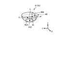
- FIG. 1 is a diagram showing an example of the overall configuration of an image processing system 1 of this embodiment.
- the image processing system 1 includes an image processing device 10 , an imaging unit 12 , a detection unit 14 and a display unit 16 .
- the image processing device 10, the imaging unit 12, the detection unit 14, and the display unit 16 are connected so as to be able to exchange data or signals.
- the image processing device 10 the imaging unit 12, the detection unit 14, and the display unit 16 are mounted on the moving body 2 as an example.
- the image processing apparatus 10 according to the first embodiment is an example that uses Visual SLAM (Simultaneous Localization and Mapping) processing.
- the mobile object 2 is an object that can move.
- the mobile object 2 is, for example, a vehicle, a flyable object (a manned airplane, an unmanned airplane (eg, UAV (Unmanned Aerial Vehicle), drone)), a robot, or the like.
- the moving object 2 is, for example, a moving object that advances through human driving operation, or a moving object that can automatically advance (autonomously advance) without human driving operation.
- Vehicles are, for example, two-wheeled vehicles, three-wheeled vehicles, and four-wheeled vehicles. In this embodiment, a case where the vehicle is a four-wheeled vehicle capable of autonomously traveling will be described as an example.
- the image processing device 10 is not limited to being mounted on the moving body 2.
- the image processing device 10 may be mounted on a stationary object.
- a stationary object is an object that is fixed to the ground.
- a stationary object is an object that cannot move or an object that is stationary with respect to the ground.
- Stationary objects are, for example, traffic lights, parked vehicles, road signs, and the like.
- the image processing apparatus 10 may be installed in a cloud server that executes processing on the cloud.
- the photographing unit 12 photographs the surroundings of the moving object 2 and acquires photographed image data.
- the photographed image data is simply referred to as a photographed image.
- the photographing unit 12 is, for example, a digital camera capable of photographing moving images. It should be noted that photographing refers to converting an image of a subject formed by an optical system such as a lens into an electrical signal.
- the photographing unit 12 outputs the photographed image to the image processing device 10 . Also, in the present embodiment, the description will be made on the assumption that the photographing unit 12 is a monocular fisheye camera (for example, the viewing angle is 195 degrees).
- imaging units 12 imaging units 12A to 12D
- a plurality of photographing units 12 photograph subjects in respective photographing areas E (photographing areas E1 to E4) to obtain photographed images.
- the photographing directions of the plurality of photographing units 12 are different from each other. Further, it is assumed that the photographing directions of the plurality of photographing units 12 are adjusted in advance so that at least a part of the photographing area E overlaps between adjacent photographing units 12 .
- the four imaging units 12A to 12D are an example, and the number of imaging units 12 is not limited.
- the moving body 2 has a vertically long shape such as a bus or a truck
- a total of six imaging units 12 can be used by arranging the imaging units 12 one by one. That is, depending on the size and shape of the moving body 2, the number and arrangement positions of the imaging units 12 can be arbitrarily set.
- the process of determining the boundary angle which will be described later, can be realized by providing at least two imaging units 12 .
- the detection unit 14 detects position information of each of a plurality of detection points around the moving object 2 . In other words, the detection unit 14 detects the position information of each detection point in the detection area F.
- FIG. A detection point indicates each point individually observed by the detection unit 14 in the real space.
- a detection point corresponds to, for example, a three-dimensional object around the moving object 2 .
- the position information of the detection point is information that indicates the position of the detection point in real space (three-dimensional space).
- the position information of the detection point is information indicating the distance from the detection unit 14 (that is, the position of the moving body 2) to the detection point and the direction of the detection point with respect to the detection unit 14.
- FIG. These distances and directions can be represented, for example, by position coordinates indicating the relative positions of the detection points with respect to the detection unit 14, position coordinates indicating the absolute positions of the detection points, vectors, or the like.
- the detection unit 14 is, for example, a 3D (Three-Dimensional) scanner, a 2D (Two-Dimensional) scanner, a distance sensor (millimeter wave radar, laser sensor), a sonar sensor that detects an object with sound waves, an ultrasonic sensor, and the like.
- the laser sensor is, for example, a three-dimensional LiDAR (Laser Imaging Detection and Ranging) sensor.
- the detection unit 14 may be a device using SfM (Structure from Motion) technology for measuring the distance from an image captured by a monocular camera.
- a plurality of imaging units 12 may be used as the detection unit 14 .
- one of the multiple imaging units 12 may be used as the detection unit 14 .
- the display unit 16 displays various information.
- the display unit 16 is, for example, an LCD (Liquid Crystal Display) or an organic EL (Electro-Luminescence) display.
- the image processing device 10 is communicably connected to an electronic control unit (ECU: Electronic Control Unit) 3 mounted on the mobile object 2 .
- the ECU 3 is a unit that electronically controls the moving body 2 .
- the image processing apparatus 10 is capable of receiving CAN (Controller Area Network) data such as the speed and moving direction of the moving body 2 from the ECU 3 .
- CAN Controller Area Network
- FIG. 2 is a diagram showing an example of the hardware configuration of the image processing device 10. As shown in FIG.
- the image processing apparatus 10 includes a CPU (Central Processing Unit) 10A, a ROM (Read Only Memory) 10B, a RAM (Random Access Memory) 10C, and an I/F (Interface) 10D, and is, for example, a computer.
- the CPU 10A, ROM 10B, RAM 10C, and I/F 10D are interconnected by a bus 10E, and have a hardware configuration using a normal computer.
- the CPU 10A is an arithmetic device that controls the image processing device 10.
- CPU 10A corresponds to an example of a hardware processor.
- the ROM 10B stores programs and the like for realizing various processes by the CPU 10A.
- the RAM 10C stores data required for various processes by the CPU 10A.
- the I/F 10D is an interface for connecting to the imaging unit 12, the detection unit 14, the display unit 16, the ECU 3, and the like, and for transmitting and receiving data.
- a program for executing image processing executed by the image processing apparatus 10 of the present embodiment is pre-installed in the ROM 10B or the like and provided.
- the program executed by the image processing apparatus 10 of the present embodiment may be configured to be provided by being recorded on a recording medium in the form of a file in a format installable or executable in the image processing apparatus 10 .
- a recording medium is a computer-readable medium. Recording media include CD (Compact Disc)-ROM, flexible disk (FD), CD-R (Recordable), DVD (Digital Versatile Disk), USB (Universal Serial Bus) memory, SD (Secure Digital) card, and the like.
- the image processing device 10 simultaneously estimates the position information of the detection point and the self-position information of the moving body 2 from the captured image captured by the imaging unit 12 by Visual SLAM processing.
- the image processing device 10 joins together a plurality of spatially adjacent captured images to generate and display a composite image that provides a bird's-eye view of the surroundings of the moving body 2 .
- the imaging unit 12 is used as the detection unit 14 in this embodiment.
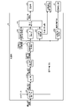
- FIG. 3 is a diagram showing an example of the functional configuration of the image processing device 10. As shown in FIG. In addition to the image processing device 10, FIG. 3 also shows the photographing unit 12 and the display unit 16 in order to clarify the data input/output relationship.
- the image processing apparatus 10 includes an acquisition unit 20, a selection unit 23, a Visual-SLAM processing unit 24 (hereinafter referred to as "VSLAM processing unit 24"), a determination unit 30, a deformation unit 32, and a virtual viewpoint line of sight determination unit.
- VSLAM processing unit 24 Visual-SLAM processing unit 24
- a unit 34 a projection conversion unit 36 , and an image synthesis unit 38 are provided.
- a part or all of the plurality of units may be realized by, for example, causing a processing device such as the CPU 10A to execute a program, that is, by software. Also, some or all of the plurality of units may be realized by hardware such as an IC (Integrated Circuit), or may be realized by using software and hardware together.
- a processing device such as the CPU 10A to execute a program
- a program that is, by software.
- some or all of the plurality of units may be realized by hardware such as an IC (Integrated Circuit), or may be realized by using software and hardware together.
- the acquisition unit 20 acquires the captured image from the imaging unit 12.
- the obtaining unit 20 obtains a captured image from each of the imaging units 12 (imaging units 12A to 12D).
- the acquisition unit 20 outputs the acquired captured image to the projection conversion unit 36 and the selection unit 23 every time it acquires a captured image.
- the selection unit 23 selects the detection area of the detection point.
- the selection unit 23 selects a detection region by selecting at least one imaging unit 12 from among the plurality of imaging units 12 (imaging units 12A to 12D).
- the selection unit 23 uses the vehicle state information and the detection direction information included in the CAN data received from the ECU 3, or the instruction information input by the user's operation instruction to select at least one of the photographing units. Select 12.
- the vehicle state information is, for example, information indicating the traveling direction of the moving body 2, the state of the direction indication of the moving body 2, the state of the gear of the moving body 2, and the like. Vehicle state information can be derived from CAN data.
- the detection direction information is information indicating the direction in which the information of interest is detected, and can be derived by POI (Point Of Interest) technology.
- the instruction information is information indicating a direction in which attention should be paid, and is input by a user's operation instruction.
- the selection unit 23 selects the direction of the detection area using the vehicle state information. Specifically, the selection unit 23 uses the vehicle state information to specify parking information such as rear parking information indicating rear parking of the moving body 2 and parallel parking information indicating parallel parking.
- the selection unit 23 associates the parking information with the identification information of any one of the imaging units 12 and stores them in advance. For example, the selection unit 23 stores in advance the identification information of the photographing unit 12D (see FIG. 1) that photographs the rear of the moving body 2 in association with the rear parking information. In addition, the selection unit 23 stores in advance identification information of each of the image capturing units 12B and 12C (see FIG. 1) that capture images of the moving body 2 in the horizontal direction in association with the parallel parking information.
- the selection unit 23 selects the direction of the detection area by selecting the imaging unit 12 corresponding to the parking information derived from the received vehicle state information.
- the selection unit 23 may select the imaging unit 12 having the imaging area E in the direction indicated by the detection direction information. Further, the selection unit 23 may select the imaging unit 12 having the imaging area E in the direction indicated by the detection direction information derived by the POI technique.
- the selection unit 23 outputs, to the VSLAM processing unit 24 , the selected image captured by the image capturing unit 12 among the captured images acquired by the acquisition unit 20 .
- the VSLAM processing unit 24 executes Visual SLAM processing using the captured image received from the selection unit 23 to generate environment map information, and outputs the generated environment map information to the determination unit 30 .
- the VSLAM processing unit 24 includes a matching unit 25, a storage unit 26, a self-position estimation unit 27, a correction unit 28, and a three-dimensional reconstruction unit 29.
- the matching unit 25 performs feature amount extraction processing and matching processing between images for a plurality of captured images with different capturing timings (a plurality of captured images with different frames). Specifically, the matching unit 25 performs feature quantity extraction processing from these multiple captured images. The matching unit 25 performs a matching process of identifying corresponding points between the plurality of captured images by using feature amounts between the plurality of captured images captured at different timings. The matching section 25 outputs the matching processing result to the self-position estimation section 27 .
- the self-position estimation unit 27 uses a plurality of matching points acquired from the matching unit 25 to estimate the self-position relative to the captured image by projective transformation or the like.
- the self-position includes information on the position (three-dimensional coordinates) and inclination (rotation) of the photographing unit 12, and the self-position estimation unit 27 stores this as self-position information in the environment map information 26A.
- the three-dimensional reconstruction unit 29 performs perspective projection conversion processing using the movement amount (translation amount and rotation amount) of the self-position estimated by the self-position estimation unit 27, and the three-dimensional coordinates of the matching point (relative to the self-position coordinates).
- the three-dimensional reconstruction unit 29 stores the determined three-dimensional coordinates in the environmental map information 26A as peripheral position information.
- the storage unit 26 stores various data.
- the storage unit 26 is, for example, a RAM, a semiconductor memory device such as a flash memory, a hard disk, an optical disk, or the like.
- the storage unit 26 may be a storage device provided outside the image processing apparatus 10 .
- the storage unit 26 may be a storage medium. Specifically, the storage medium may store or temporarily store programs and various types of information downloaded via a LAN (Local Area Network), the Internet, or the like.
- LAN Local Area Network
- the environment map information 26A is information in which the peripheral position information calculated by the three-dimensional reconstruction unit 29 and the self-position information calculated by the self-position estimation unit 27 are registered in a three-dimensional coordinate space with a predetermined position in the real space as the origin. .
- the predetermined position in the real space may be determined, for example, based on preset conditions.
- the predetermined position is the position of the moving body 2 when the image processing device 10 executes the image processing of this embodiment.
- the image processing apparatus 10 may set the position of the moving body 2 when it is determined that the predetermined timing is reached as the predetermined position.
- the image processing device 10 may determine that the predetermined timing has been reached when it determines that the behavior of the moving body 2 indicates a parking scene.
- the behavior indicating the parking scene is, for example, when the speed of the moving body 2 becomes equal to or less than a predetermined speed, when the gear of the moving body 2 is put into the reverse gear, or the like, a signal indicating the start of parking is received by an operation instruction of the user.
- a predetermined speed is not limited to the parking scene.
- FIG. 4 is a schematic diagram of an example of the environment map information 26A.
- the environmental map information 26A includes positional information (peripheral positional information) of each detection point P and self-positional information of the self-position S of the moving body 2, which corresponds in the three-dimensional coordinate space. It is information registered at the coordinate position to be used.
- self-positions S of self-position S1 to self-position S3 are shown.
- a larger numerical value following S means that the self-position S is closer to the current timing.
- the correction unit 28 calculates the sum of distance differences in the three-dimensional space between the three-dimensional coordinates calculated in the past and the newly calculated three-dimensional coordinates for points matched multiple times between a plurality of frames. is minimized, the peripheral location information and self-location information registered in the environmental map information 26A are corrected using, for example, the method of least squares. Note that the correction unit 28 may correct the movement amount (translation amount and rotation amount) of the self-position used in the process of calculating the self-position information and the peripheral position information.
- the timing of correction processing by the correction unit 28 is not limited.
- the correction unit 28 may perform the above correction process at predetermined timings.
- the predetermined timing may be determined, for example, based on preset conditions.
- the image processing apparatus 10 will be described as an example in which the correction unit 28 is provided. However, the image processing apparatus 10 may be configured without the correction section 28 .
- the determination unit 30 receives the environment map information from the VSLAM processing unit 24, and uses the surrounding position information and self-position information accumulated in the environment map information 26A to calculate the measured distance between the moving object 2 and surrounding three-dimensional objects.
- the measured distance means the distance between objects measured by processing using a distance sensor or an image (VSLAM processing in this embodiment). Since the measured distance is a distance obtained by processing using a distance sensor or an image, it can take any value depending on the situation. In that sense, the measured distance is a continuous value.
- the determination unit 30 executes distance stabilization processing for converting the measured distance into a stabilized distance.
- the stabilized distance means a discrete distance (non-continuous value) obtained based on the measured distance. This distance stabilization processing will be described later in detail. Note that the determination unit 30 is an example of a conversion unit.
- the determination unit 30 determines the projection shape of the projection plane using the stabilized distance obtained by the distance stabilization process, and generates projection shape information.
- the determining unit 30 outputs the generated projection shape information to the transforming unit 32 .
- the projection plane is a three-dimensional plane for projecting the peripheral image of the moving object 2.
- the peripheral image of the moving body 2 is a captured image of the periphery of the moving body 2, and is a captured image captured by each of the imaging units 12A to 12D.
- the projected shape on the projection plane is a three-dimensional (3D) shape that is virtually formed in a virtual space corresponding to the real space.
- the determination of the projection shape of the projection plane executed by the determination unit 30 is called projection shape determination processing.
- the determination unit 30 calculates an asymptotic curve of the surrounding position information with respect to the self position using the surrounding position information of the moving body 2 and the self-position information accumulated in the environment map information 26A.
- FIG. 5 is an explanatory diagram of the asymptotic curve Q generated by the determining unit 30.
- the asymptotic curve is an asymptotic curve of a plurality of detection points P in the environmental map information 26A.
- FIG. 5 is an example showing an asymptotic curve Q in a projection image obtained by projecting a photographed image onto a projection plane when the moving body 2 is viewed from above.
- the determination unit 30 has identified three detection points P in order of proximity to the self-position S of the mobile object 2 .
- the determination unit 30 generates an asymptotic curve Q for these three detection points P.
- the determination unit 30 outputs the self-position and the asymptotic curve information to the virtual viewpoint line-of-sight determination unit 34 .
- the configuration of the determination unit 30 will be explained later in detail.
- the transformation unit 32 transforms the projection plane based on the projection shape information received from the determination unit 30.
- FIG. 6 is a schematic diagram showing an example of the reference projection plane 40.
- FIG. FIG. 7 is a schematic diagram showing an example of the projection shape 41 determined by the determination unit 30.
- the transforming unit 32 transforms the pre-stored reference projection plane shown in FIG. 6 based on the projection shape information, and determines the transformed projection plane 42 as the projection shape 41 shown in FIG.
- the determination unit 30 generates modified projection plane information based on the projection shape 41 .
- This deformation of the reference projection plane is performed, for example, using the detection point P closest to the moving object 2 as a reference.
- the deformation section 32 outputs the deformation projection plane information to the projection conversion section 36 .
- the transforming unit 32 transforms the reference projection plane into a shape along an asymptotic curve of a predetermined number of detection points P in order of proximity to the moving body 2 based on the projection shape information.
- the virtual viewpoint line-of-sight determination unit 34 determines virtual viewpoint line-of-sight information based on the self-position and the asymptotic curve information.
- the virtual viewpoint line-of-sight determining unit 34 determines, for example, a direction passing through the detection point P closest to the self-position S of the moving body 2 and perpendicular to the modified projection plane as the line-of-sight direction. Further, the virtual viewpoint line-of-sight determination unit 34 fixes the direction of the line-of-sight direction L, for example, and sets the coordinates of the virtual viewpoint O to an arbitrary Z coordinate and an arbitrary Z coordinate in the direction away from the asymptotic curve Q toward the self-position S. Determined as XY coordinates.
- the XY coordinates may be coordinates of a position farther from the asymptotic curve Q than the self-position S.
- the virtual viewpoint line-of-sight determination unit 34 outputs virtual viewpoint line-of-sight information indicating the virtual viewpoint O and the line-of-sight direction L to the projection conversion unit 36 .
- the line-of-sight direction L may be a direction from the virtual viewpoint O to the position of the vertex W of the asymptotic curve Q.
- the projection conversion unit 36 generates a projection image by projecting the photographed image acquired from the photographing unit 12 onto the deformed projection plane based on the deformed projection plane information and the virtual viewpoint line-of-sight information.
- the projection conversion unit 36 converts the generated projection image into a virtual viewpoint image and outputs the virtual viewpoint image to the image synthesis unit 38 .
- a virtual viewpoint image is an image of a projected image viewed in an arbitrary direction from a virtual viewpoint.
- the projection image generation processing by the projection conversion unit 36 will be described in detail with reference to FIG.
- the projection conversion unit 36 projects the captured image onto the modified projection plane 42 .
- the projection conversion unit 36 generates a virtual viewpoint image, which is an image of the photographed image projected onto the modified projection plane 42 viewed in the line-of-sight direction L from an arbitrary virtual viewpoint O (not shown).
- the position of the virtual viewpoint O may be the latest self-position S of the moving body 2, for example.
- the XY coordinate values of the virtual viewpoint O may be set to the XY coordinate values of the latest self-position S of the moving object 2 .
- the value of the Z coordinate (position in the vertical direction) of the virtual viewpoint O may be the value of the Z coordinate of the detection point P closest to the self-position S of the moving body 2 .
- the line-of-sight direction L may be determined, for example, based on a predetermined criterion.
- the line-of-sight direction L may be, for example, the direction from the virtual viewpoint O toward the detection point P closest to the self-position S of the moving object 2 . Also, the line-of-sight direction L may be a direction that passes through the detection point P and is perpendicular to the modified projection plane 42 .
- the virtual viewpoint line-of-sight information indicating the virtual viewpoint O and the line-of-sight direction L is created by the virtual viewpoint line-of-sight determination unit 34 .
- the virtual viewpoint line-of-sight determination unit 34 may determine the line-of-sight direction L as a direction that passes through the detection point P closest to the self-position S of the moving body 2 and that is perpendicular to the modified projection plane 42 .
- the virtual viewpoint line-of-sight determination unit 34 fixes the direction of the line-of-sight direction L, and sets the coordinates of the virtual viewpoint O to an arbitrary Z coordinate and an arbitrary XY coordinate in the direction away from the asymptotic curve Q toward the self-position S. may be determined as In that case, the XY coordinates may be coordinates of a position farther from the asymptotic curve Q than the self-position S.
- the virtual viewpoint line-of-sight determination unit 34 outputs virtual viewpoint line-of-sight information indicating the virtual viewpoint O and the line-of-sight direction L to the projection conversion unit 36 .
- the line-of-sight direction L may be a direction from the virtual viewpoint O to the position of the vertex W of the asymptotic curve Q.
- the projection conversion unit 36 receives virtual viewpoint line-of-sight information from the virtual viewpoint line-of-sight determination unit 34 .
- the projection conversion unit 36 identifies the virtual viewpoint O and the line-of-sight direction L by receiving the virtual viewpoint line-of-sight information. Then, the projection conversion unit 36 generates a virtual viewpoint image, which is an image viewed in the line-of-sight direction L from the virtual viewpoint O, from the photographed image projected onto the modified projection plane 42 .
- the projective transformation unit 36 outputs the virtual viewpoint image to the image synthesizing unit 38 .
- the image composition unit 38 generates a composite image by extracting part or all of the virtual viewpoint image.
- the image synthesizing unit 38 performs a process of joining a plurality of virtual viewpoint images (here, four virtual viewpoint images corresponding to the photographing units 12A to 12D) in the boundary area between the photographing units.
- the image composition unit 38 outputs the generated composite image to the display unit 16.
- the synthesized image may be a bird's-eye view image with a virtual viewpoint O above the mobile object 2, or an image in which the virtual viewpoint O is inside the mobile object 2 and the mobile object 2 is displayed semi-transparently.
- the projection conversion unit 36 and the image synthesizing unit 38 constitute an image generation unit 37 .
- FIG. 8 is a schematic diagram showing an example of the configuration of the determination unit 30.
- the determination unit 30 includes an absolute distance conversion unit 30A, an extraction unit 30B, a nearest neighbor identification unit 30C, a distance stabilization processing unit 30I, a reference projection plane shape selection unit 30D, a scale It includes a determination unit 30E, an asymptotic curve calculation unit 30F, a shape determination unit 30G, and a boundary area determination unit 30H.
- the absolute distance conversion unit 30A converts the relative positional relationship between the self-position and the surrounding three-dimensional objects, which can be known from the environment map information 26A, into the absolute value of the distance from the self-position to the surrounding three-dimensional objects.
- the speed data of the mobile object 2 included in the CAN data received from the ECU 3 of the mobile object 2 is used.
- the relative positional relationship between the self-position S and the plurality of detection points P is known, but the absolute value of the distance is not calculated.
- the distance between the self-position S3 and the self-position S2 can be obtained from the frame-to-frame cycle for calculating the self-position and the speed data during the interval based on the CAN data. Since the relative positional relationship of the environment map information 26A is similar to the real space, knowing the distance between the self-position S3 and the self-position S2 allows the distance from the self-position S to all other detection points P to be detected.
- the absolute value of the distance (measured distance) can also be determined.
- the absolute distance conversion unit 30A may be omitted.
- the absolute distance conversion unit 30A outputs the calculated measured distance of each of the plurality of detection points P to the extraction unit 30B. Further, the absolute distance conversion unit 30A outputs the calculated current position of the moving object 2 to the virtual viewpoint line of sight determination unit 34 as self-position information of the moving object 2 .
- the extraction unit 30B extracts detection points P existing within a specific range from among the plurality of detection points P whose measured distances are received from the absolute distance conversion unit 30A.
- the specific range is, for example, a range from the road surface on which the mobile body 2 is arranged to a height corresponding to the vehicle height of the mobile body 2 .
- the range is not limited to this range.
- the extraction unit 30B extracts the detection points P of, for example, an object that obstructs the movement of the moving body 2 or an object positioned adjacent to the moving body 2. can be done.
- the extraction unit 30B outputs the measured distance of each of the extracted detection points P to the nearest neighbor identification unit 30C.
- the nearest neighbor identification unit 30C divides the circumference of the self-position S of the moving body 2 into specific ranges (for example, angle ranges), and for each range, the closest detection point P to the moving body 2 or the closest detection point to the moving body 2. A plurality of detection points P are specified in order.
- the nearest neighbor identification unit 30C identifies the detection point P using the measured distance received from the extraction unit 30B. In the present embodiment, the nearest neighbor identifying unit 30C identifies a plurality of detection points P in order of proximity to the moving body 2 for each range as an example.
- the nearest neighbor identification unit 30C outputs the measured distance of the detection point P identified for each range to the distance stabilization processing unit 30I.
- the distance stabilization processing unit 30I executes distance stabilization processing for converting the measured distance into a stabilized distance.
- the distance stabilization processing executed by the distance stabilization processing section 30I includes first distance stabilization processing and second distance stabilization processing. Each of the first distance stabilization process and the second distance stabilization process will be described in detail below with reference to FIGS. 9 to 14.
- FIG. 9 Each of the first distance stabilization process and the second distance stabilization process will be described in detail below with reference to FIGS. 9 to 14.
- the first distance stabilization process is based on the magnitude relationship between the measured distance of the detection point P specified for each range and the threshold, and the measured distance is the first distance as the stabilized distance or the first distance It converts to a smaller second distance.
- FIG. 9 is a plan view showing an example of a situation in which the mobile body 2 is rear-parked on the parking line PL where the pillar C exists.
- FIG. 10 is a plan view showing an example of a situation in which the moving body 2 travels backward and approaches the pillar C more than in FIG.
- the distance stabilization processing when the mobile body 2 parks backward will be explained.
- the pillar C exists in the imaging area E4 of the imaging unit 12D. Therefore, the measured distances of the plurality of detection points P regarding the pillar C specified for each range are sequentially output from the nearest neighbor specifying unit 30C to the distance stabilization processing unit 30I.
- FIG. 11 is a diagram showing an example of temporal changes in the measured distance of the detection point P of the pillar C that is closest to the moving body 2.
- the circles in FIG. 11 indicate acquisition of one measurement distance.
- the measured distance d of the detection point P becomes smaller.
- the fact that the measured distance d increases from the time tr indicates that the moving body 2 has once moved forward due to the fact that the moving body 2 turns back when parking backwards.
- the measured distance d fluctuates including a slight increase or decrease in addition to the amount of change associated with backward movement of the moving body 2 in the period up to time tr , for example. do.
- This variation is due to measurement errors (fluctuations in measured values due to noise and other factors) of the measured distance obtained using the sensor (in the case of this embodiment, the measured distance obtained by Visual SLAM processing using the captured image). This is due to
- first fluctuation of the projection plane when the projection plane is deformed according to the fluctuating measurement distance d as shown in FIG. It frequently deforms in the receding direction (this phenomenon is hereinafter also referred to as "first fluctuation of the projection plane").
- first fluctuation of the projection plane when an image (projected image) projected onto a projection plane with temporal fluctuation is displayed, the projected image fluctuates and the image appears to be distorted.
- the first distance stabilization process solves such a problem that the projection image becomes unnatural due to the first fluctuation of the projection plane.
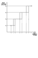
- FIG. 12 is a graph showing an example of the relationship between the input and output of the distance stabilization processing section 30I.
- the horizontal axis indicates the measured distance d which is the input of the distance stabilization processing section 30I
- the vertical axis indicates the stabilized distance D which is the output of the distance stabilization processing section 30I.
- the distance stabilization processing unit 30I keeps the measured distance d at Convert to stabilized distance D1 and output.
- the distance stabilization processing section 30I converts the measured distance d into a stabilized distance D2 and outputs it.
- the threshold d3 is an example of a first threshold as a down determination threshold (threshold for determining down of the stabilization distance).
- the stabilization distance D 1 and the stabilization distance D 2 are examples of a first distance as a stabilization distance before down and a second distance as a stabilization distance after down, respectively.
- the distance stabilization processing unit 30I stabilizes the measured distance d until it becomes smaller than the threshold d5 which is smaller than the threshold d3 after the measured distance d becomes smaller than the threshold d3 . Convert to distance D2 and output.
- the distance stabilization processing section 30I converts the measured distance d into a stabilized distance D3 and outputs it.
- the threshold d5 is an example of the third threshold as the down determination threshold.
- the stabilization distance D 2 and the stabilization distance D 3 are examples of the second distance as the stabilization distance before down and the third distance as the stabilization distance after down, respectively.
- the distance stabilization processing unit 30I converts the measured distance d into the stabilized distance D3 and outputs it until the successively input measured distance d becomes smaller than the threshold value d7 .
- the distance stabilization processing unit 30I changes the measured distance d to the stabilized distance D4 as the stabilized distance after down. converted to and output.
- the deformation section 32 deforms the projection plane using the information of the stabilization distance D, so that the fluctuation of the projection plane can be suppressed.
- the second distance stabilization process further eliminates the problem that the projection image becomes unnatural due to the temporal fluctuation of the projection plane when the first distance stabilization process is executed. That is, after the measured distance becomes smaller than the first threshold, the second distance stabilization process is based on the magnitude relationship between the acquired measured distance and the second threshold larger than the first threshold. to convert the measured distance into a first distance or a second distance.
- FIG. 13 is a diagram showing an example of temporal changes in the stabilized distance D obtained by the first distance stabilization process using the measured distance d of the detection point P of the pillar C shown in FIG. 11 as an input. .
- the measured distance d in FIG. 11 including many fluctuations can be converted into a stabilized distance D with less fluctuation. Therefore, it is possible to display a stable projected image using a projection plane in which fluctuation is suppressed.
- the stabilization distance D fluctuates between D1 and D2 in the period from time t2 to time t3 .
- the stabilization distance D is between D2 and D3 in the period from time t4 to time t5 , and between D3 and D4 in the period from time t6 to time t7 .
- it fluctuates between D4 and D5 .
- Fluctuations in the stabilization distance D in each of the above periods are, for example, in the period from time t2 to time t3 shown in FIG. This is because the fluctuation of increasing and decreasing is repeated, and the stabilization distance D also fluctuates between D1 and D2 in conjunction with this fluctuation.
- the shape of the projection plane is determined according to the value of the stabilization distance D. Therefore, during the period from time t2 to time t3 corresponding to before and after the switching of the stabilization distance, the deformation of the projection plane frequently occurs in conjunction with the fluctuation of the stabilization distance D (hereinafter referred to as This phenomenon is also called "the second fluctuation of the projection plane"). As a result, the projected image that is stably displayed by the first distance stabilization process is changed from the projected image to Image disturbance occurs.
- the second distance stabilization process solves such a problem that the projection image becomes unnatural due to the second fluctuation of the projection plane.
- the distance stabilization processing unit 30I determines that the measured distance d is smaller than the threshold value d3 . does not convert the stabilization distance D to D1 , even if That is, when the measured distance d is smaller than the threshold d3 , the distance stabilization processing unit 30I sets the stabilized distance D to D1 as long as the measured distance d does not exceed the threshold d2 , which is larger than the threshold d3 . do not convert to Therefore, the dead zone is between the threshold d3 and the threshold d2 .
- the threshold d3 is an example of the first threshold as the down determination threshold.
- the threshold d2 is an example of a second threshold as an up determination threshold (threshold for determining whether the stabilization distance is increased).
- the distance stabilization processing unit 30I sets the stabilized distance D to D2 as long as the measured distance d does not exceed the threshold d4 , which is larger than the threshold d5 . do not convert to Therefore, the dead zone is between the threshold d5 and the threshold d4 .
- the threshold d5 is an example of a first threshold as a down determination threshold
- the threshold d4 is an example of a second threshold as an up determination threshold.
- the distance stabilization processing unit 30I sets the measured distance d to the threshold value d7 . Do not convert the stabilization distance D to D3 , even if it becomes greater than . That is, when the measured distance d is smaller than the threshold d7 , the distance stabilization processing unit 30I sets the stabilized distance D to D3 as long as the measured distance d does not exceed the threshold d6 , which is larger than the threshold d7 . do not convert to Therefore, the dead zone is between the threshold d7 and the threshold d6 .
- the threshold d7 is an example of a first threshold as a down determination threshold
- the threshold d6 is an example of a second threshold as an up determination threshold.
- the second distance stabilization process according to the relationship between the input and the output shown in FIG.
- the value of the stabilization distance D is determined not by the magnitude relationship with the threshold value of , but by the magnitude relationship with a second threshold value that is greater than the first threshold value. That is, the value of the stabilization distance D is controlled according to the history of the measured distance d. In that sense, the second distance stabilization process can be called a stabilization distance D hysteresis process.
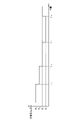
- FIG. 14 is a diagram showing an example of temporal changes in the stabilized distance D obtained by the first and second distance stabilization processing using the measured distance of the detection point P of the pillar C shown in FIG. 11 as an input. is.
- the time when the stabilization distance D is converted from D1 to D2 is t'3
- the time when D2 is converted to D3 is t'5
- the stabilization distance D is converted from D3 to D4 .
- the time at which D4 is converted to D3 is t'8 .
- fluctuations in the stabilization distance D during periods before and after each down determination threshold value or up determination threshold value are eliminated.
- the dead zone defined by the thresholds d3 and d2 , the dead zone defined by the thresholds d5 and d4 , and the dead zone defined by the thresholds d7 and d6 are respectively different lengths. This is because the accuracy of the distance sensor (the VSLAM processing unit 24 in this case) varies depending on the measured distance from the moving body 2 to the three-dimensional object.
- the width of each of these dead zones can be arbitrarily set by adjusting each threshold according to the measurement accuracy of the distance sensor. For example, if the measurement accuracy of the distance sensor is ⁇ 5% of the absolute distance, the width of the dead zone may be set to increase as the measured distance d increases, as in the example shown in FIG. .
- the distance stabilization processing unit 30I changes the measured distance d to the threshold value d5 as the moving object 2 travels backward. If so, the stabilization distance D will be converted to D3 according to the first distance stabilization process.
- the thresholds d 3 and d 5 are examples of the first and third thresholds, respectively, and the stabilization distances D 2 and D 3 are examples of the second and third distances, respectively. be.
- the distance stabilization processing unit 30I applies the stabilization distance of the detection point P specified for each range obtained by the distance stabilization processing to the reference projection plane shape selection unit 30D, the scale determination unit 30E, the asymptotic curve calculation unit 30F, It is output to the boundary area determining section 30H.
- the reference projection plane shape selection unit 30D selects the shape of the reference projection plane.
- the reference projection plane 40 is, for example, a projection plane having a shape that serves as a reference when changing the shape of the projection plane.
- the shape of the reference projection plane 40 is, for example, a bowl shape, a cylinder shape, or the like. Note that FIG. 6 illustrates a bowl-shaped reference projection plane 40 .
- a bowl shape is a shape having a bottom surface 40A and a side wall surface 40B, one end of the side wall surface 40B continuing to the bottom surface 40A, and the other end being open.
- the side wall surface 40B increases in horizontal cross-sectional width from the bottom surface 40A side toward the opening side of the other end.
- the bottom surface 40A is circular, for example.
- the circular shape includes a perfect circular shape and a circular shape other than a perfect circular shape such as an elliptical shape.
- a horizontal section is an orthogonal plane perpendicular to the vertical direction (direction of arrow Z).
- the orthogonal plane is a two-dimensional plane along an arrow X direction orthogonal to the arrow Z direction and an arrow Y direction orthogonal to the arrow Z direction and the arrow X direction.
- the horizontal section and the orthogonal plane may be hereinafter referred to as the XY plane.
- the bottom surface 40A may have a shape other than a circular shape, such as an oval shape.
- a cylindrical shape is a shape consisting of a circular bottom surface 40A and side wall surfaces 40B that are continuous with the bottom surface 40A.
- the side wall surface 40B forming the cylindrical reference projection plane 40 has a cylindrical shape with one end opening continuing to the bottom surface 40A and the other end being open.
- the side wall surface 40B forming the cylindrical reference projection plane 40 has a shape whose diameter in the XY plane is substantially constant from the bottom surface 40A side toward the opening side of the other end.
- the bottom surface 40A may have a shape other than a circular shape, such as an oval shape.
- the reference projection plane 40 is a three-dimensional model that is virtually formed in a virtual space in which the bottom surface 40A substantially coincides with the road surface below the moving body 2 and the center of the bottom surface 40A is the self-position S of the moving body 2. be.
- the reference projection plane shape selection unit 30D selects the shape of the reference projection plane 40 by reading one specific shape from a plurality of types of reference projection planes 40 .
- the reference projection plane shape selection unit 30D selects the shape of the reference projection plane 40 based on the positional relationship between the self-position and surrounding three-dimensional objects, the stabilization distance, and the like. It should be noted that the shape of the reference projection plane 40 may be selected by a user's operation instruction.
- the reference projection plane shape selection section 30D outputs the determined shape information of the reference projection plane 40 to the shape determination section 30G. In this embodiment, as described above, the reference projection plane shape selection unit 30D selects the bowl-shaped reference projection plane 40 as an example.
- the scale determination unit 30E determines the scale of the reference projection plane 40 having the shape selected by the reference projection plane shape selection unit 30D.
- the scale determination unit 30E determines, for example, to reduce the scale when there are a plurality of detection points P within a predetermined distance range from the self-position S.
- the scale determining section 30E outputs scale information of the determined scale to the shape determining section 30G.
- the asymptotic curve calculation unit 30F uses each of the stabilization distances of the detection points P closest to the self-position S for each range from the self-position S received from the nearest neighbor identification unit 30C to determine the asymptotic curve of the calculated asymptotic curve Q.
- the curve information is output to the shape determination section 30G and the virtual viewpoint line of sight determination section 34 .
- the asymptotic curve calculation unit 30F may calculate the asymptotic curve Q of the detection points P accumulated for each of a plurality of portions of the reference projection plane 40 . Then, the asymptotic curve calculation unit 30F may output the calculated asymptotic curve information of the asymptotic curve Q to the shape determination unit 30G and the virtual viewpoint line of sight determination unit 34 .
- the shape determination unit 30G enlarges or reduces the reference projection plane 40 having the shape indicated by the shape information received from the reference projection plane shape selection unit 30D to the scale of the scale information received from the scale determination unit 30E. Then, the shape determination unit 30G transforms the reference projection plane 40 after being enlarged or reduced so as to conform to the asymptotic curve information of the asymptotic curve Q received from the asymptotic curve calculation unit 30F, and determines the projection shape. Determined as
- the shape determining unit 30G deforms the reference projection plane 40 into a shape passing through the detection point P closest to the self-position S of the moving body 2, which is the center of the bottom surface 40A of the reference projection plane 40.
- the shape is determined as projected shape 41 .
- the shape passing through the detection point P means that the side wall surface 40B after deformation has a shape passing through the detection point P.
- the self-position S is the latest self-position S calculated by the self-position estimator 27 .
- the shape determination unit 30G adjusts the bottom surface so that when the reference projection plane 40 is deformed, a partial region of the side wall surface 40B becomes a wall surface passing through the detection point P closest to the moving body 2.
- a deformed shape of a partial region of 40A and side wall surface 40B is determined as a projected shape 41 .
- the projected shape 41 after deformation is, for example, a shape raised from a rising line 44 on the bottom surface 40A in a direction approaching the center of the bottom surface 40A from the viewpoint of the XY plane (planar view).
- Raising means, for example, moving part of the side wall surface 40B and the bottom surface 40A closer to the center of the bottom surface 40A so that the angle between the side wall surface 40B and the bottom surface 40A of the reference projection plane 40 becomes smaller. It means to bend or fold in a direction. In the raised shape, the raised line 44 may be positioned between the bottom surface 40A and the side wall surface 40B, and the bottom surface 40A may remain undeformed.
- the shape determination unit 30G determines to deform the specific area on the reference projection plane 40 so as to protrude to a position passing through the detection point P from the viewpoint of the XY plane (planar view). The shape and range of the specific area may be determined based on predetermined criteria. Then, the shape determination unit 30G deforms the reference projection plane 40 so that the distance from the self-position S continuously increases from the protruded specific region toward regions other than the specific region on the side wall surface 40B. It is determined to have a shape that
- the projection shape 41 it is preferable to determine the projection shape 41 so that the shape of the outer circumference of the cross section along the XY plane is curved.
- the shape of the outer periphery of the cross section of the projection shape 41 is, for example, a circular shape, it may be a shape other than a circular shape.
- the shape determination unit 30G may determine, as the projection shape 41, a shape obtained by deforming the reference projection plane 40 so as to follow an asymptotic curve.
- the shape determination unit 30G generates an asymptotic curve of a predetermined number of detection points P in a direction away from the detection point P closest to the self-position S of the moving body 2 .
- the number of detection points P may be plural.
- the number of detection points P is preferably three or more.
- the shape determination unit 30G preferably generates an asymptotic curve of a plurality of detection points P located at positions separated from the self-position S by a predetermined angle or more.
- the shape determination unit 30G can determine, as the projection shape 41, a shape obtained by deforming the reference projection plane 40 so as to follow the generated asymptotic curve Q. .
- the shape determination unit 30G divides the circumference of the self-position S of the moving body 2 into specific ranges, and for each range, the closest detection point P to the moving body 2, or a plurality of detection points in order of proximity to the moving body 2 A detection point P may be specified. Then, the shape determining unit 30G transforms the reference projection plane 40 into a shape passing through the detection points P specified for each range or a shape along the asymptotic curve Q of the specified plurality of detection points P, A projection shape 41 may be determined.
- the shape determination unit 30G outputs projection shape information of the determined projection shape 41 to the deformation unit 32.
- FIG. 15 is a flowchart showing an example of the flow of image processing executed by the image processing apparatus 10.
- the acquisition unit 20 acquires the captured image from the imaging unit 12 (step S10). In addition, the acquiring unit 20 acquires the directly specified content (for example, the gear of the moving body 2 is changed to the reverse gear, etc.) and the vehicle state (eg, stopped state, etc.).
- the directly specified content for example, the gear of the moving body 2 is changed to the reverse gear, etc.
- the vehicle state eg, stopped state, etc.
- the selection unit 23 selects at least two of the imaging units 12A to 12D (step S12).
- the matching unit 25 extracts feature amounts and performs matching processing using a plurality of captured images selected in step S12 and captured by the capturing unit 12 at different capturing timings from among the captured images acquired in step S10 (step S14).
- the self-position estimation unit 27 reads the environment map information 26A (surrounding position information and self-position information) (step S16).
- the self-position estimation unit 27 uses the plurality of matching points acquired from the matching unit 25 to estimate the self-position relative to the captured image by projective transformation or the like (step S18). It is registered in the environment map information 26A (step S20).
- the three-dimensional reconstruction unit 29 reads the environmental map information 26A (surrounding position information and self-position information) (step S22).
- the three-dimensional reconstruction unit 29 performs perspective projection conversion processing using the movement amount (translation amount and rotation amount) of the self-position estimated by the self-position estimation unit 27, and the three-dimensional coordinates of the matching point (relative to the self-position coordinates) are determined and registered in the environment map information 26A as peripheral position information (step S24).
- the correction unit 28 reads the environmental map information 26A (surrounding position information and self-position information).
- the correction unit 28 calculates the sum of distance differences in the three-dimensional space between the three-dimensional coordinates calculated in the past and the newly calculated three-dimensional coordinates for points matched multiple times between a plurality of frames. is minimized, the surrounding position information and self-position information registered in the environmental map information 26A are corrected (step S26) using, for example, the method of least squares, and the environmental map information 26A is updated.
- the absolute distance conversion unit 30A takes in the speed data (vehicle speed) of the mobile object 2 included in the CAN data received from the ECU 3 of the mobile object 2.
- the absolute distance conversion unit 30A uses the speed data of the moving body 2 to convert the surrounding position information included in the environment map information 26A from the current position, which is the latest self-position S of the moving body 2, to the plurality of detection points P. It is converted into distance information to each (step S28).
- the absolute distance conversion unit 30A outputs the calculated distance information of each of the plurality of detection points P to the extraction unit 30B. Further, the absolute distance conversion unit 30A outputs the calculated current position of the moving object 2 to the virtual viewpoint line of sight determination unit 34 as self-position information of the moving object 2 .
- the extraction unit 30B extracts detection points P existing within a specific range from among the plurality of detection points P for which distance information has been received (step S30).
- the nearest neighbor identification unit 30C divides the surroundings of the self-position S of the moving body 2 into specific ranges, and for each range, a detection point P closest to the moving body 2, or a plurality of detection points in order of proximity to the moving body 2 Identify P and extract the distance to the closest object (step S32).
- the nearest neighbor specifying unit 30C outputs the measured distance (measured distance between the moving body 2 and the nearest neighbor object) d of the detection point P specified for each range to the distance stabilization processing unit 30I.
- the distance stabilization processing unit 30I receives as input the measured distance d of the detection point P specified for each range, performs the first distance stabilization processing and the second distance stabilization processing, and converts the stabilized distance D into the reference projection. Output to the surface shape selection unit 30D, the scale determination unit 30E, the asymptotic curve calculation unit 30F, and the boundary area determination unit 30H (step S33).
- the asymptotic curve calculation unit 30F calculates an asymptotic curve (step S34) and outputs it to the shape determination unit 30G and the virtual viewpoint line of sight determination unit 34 as asymptotic curve information.
- the reference projection plane shape selection unit 30D selects the shape of the reference projection plane 40 (step S36), and outputs the shape information of the selected reference projection plane 40 to the shape determination unit 30G.
- the scale determination unit 30E determines the scale of the reference projection plane 40 of the shape selected by the reference projection plane shape selection unit 30D (step S38), and outputs scale information of the determined scale to the shape determination unit 30G.
- the shape determination unit 30G determines a projection shape for how to transform the shape of the reference projection plane based on the scale information and the asymptotic curve information (step S40).
- the shape determination unit 30G outputs projection shape information of the determined projection shape 41 to the deformation unit 32 .
- the transforming unit 32 transforms the shape of the reference projection plane based on the projection shape information (step S42).
- the transformation unit 32 outputs the transformed projection plane information to the projection transformation unit 36 .
- the virtual viewpoint line-of-sight determination unit 34 determines virtual viewpoint line-of-sight information based on the self-position and the asymptotic curve information (step S44).
- the virtual viewpoint line-of-sight determination unit 34 outputs virtual viewpoint line-of-sight information indicating the virtual viewpoint O and the line-of-sight direction L to the projection conversion unit 36 .
- the projection conversion unit 36 generates a projection image by projecting the photographed image acquired from the photographing unit 12 onto the deformed projection plane based on the deformed projection plane information and the virtual viewpoint line-of-sight information.
- the projection conversion unit 36 converts the generated projection image into a virtual viewpoint image (step S46) and outputs the virtual viewpoint image to the image composition unit 38 .
- the boundary area determination unit 30H determines the boundary area based on the distance to the closest object specified for each range. That is, the boundary area determination unit 30H determines a boundary area as a superimposition area of spatially adjacent peripheral images based on the position of the object closest to the moving body 2 (step S48). Boundary area determining section 30H outputs the determined boundary area to image synthesizing section 38 .
- the image composition unit 38 generates a composite image by connecting spatially adjacent perspective projection images using the boundary area (step S50). That is, the image synthesizing unit 38 joins the perspective projection images in the four directions according to the boundary area set to the angle of the nearest object direction to generate a synthetic image. Note that spatially adjacent perspective projection images are blended at a predetermined ratio in the boundary region.
- the display unit 16 displays the composite image (step S52).
- the image processing device 10 determines whether or not to end the image processing (step S54). For example, the image processing device 10 makes the determination in step S54 by determining whether or not a signal indicating that the moving body 2 should stop moving has been received from the ECU 3 . Further, for example, the image processing apparatus 10 may make the determination in step S54 by determining whether or not an instruction to end image processing has been received by an operation instruction or the like from the user.
- step S54 If a negative determination is made in step S54 (step S54: No), the processes from step S10 to step S54 are repeatedly executed.
- step S54 Yes
- step S54 when the process returns from step S54 to step S10 after executing the correction process in step S26, the subsequent correction process in step S26 may be omitted. Further, when the process returns from step S54 to step S10 without executing the correction process of step S26, the subsequent correction process of step S26 may be executed.
- the image processing apparatus 10 includes the determining section 30 as a converting section and the transforming section 32 .
- the determination unit 30 sets the measured distance as the stabilization distance to the first distance or the first distance. Convert to a second distance that is less than .
- the deformation unit 32 deforms the projection plane of the peripheral image of the moving body 2 based on the stabilization distance.
- the deformation unit 32 deforms the projection plane of the peripheral image of the moving body 2 based on the stabilization distance with less fluctuation. As a result, it is possible to suppress the temporal fluctuation of the projection plane and eliminate the problem that the projected image becomes unnatural.
- the determination unit 30 converts the measured distance into a second distance as a stabilization distance based on the magnitude relationship between the measured distance and the first threshold, and sets a second threshold that is greater than the measured distance and the first threshold. , the measured distance is converted into a first distance as a stabilization distance.
- the determining unit 30 sets the measured distance as the stabilization distance based on the magnitude relationship between the measured distance and a third threshold smaller than the first threshold. or a third distance that is less than the second distance.
- the transforming unit 32 transforms the projection plane of the peripheral image of the moving body 2 based on the second distance or the third distance obtained by converting the measured distance.
- the distance stabilization processing unit 30I Convert the distance d to the stabilization distance D4 and output it.
- the distance stabilization processing unit 30I converts the measured distance d into a stabilized distance D3 and outputs it.
- the distance stabilization processing unit 30I after the measured distance d becomes larger than the threshold value d6 and converts the stabilized distance D into D3 , the measured distance d becomes equal to the threshold value d6 . Do not convert the stabilization distance D to D 4 unless it falls below a threshold d 7 which is less than .
- Modification 2 In the above embodiment, spatial outlier removal processing, temporal outlier removal processing, spatial smoothing processing, and temporal smoothing are performed on the measured distance before the distance stabilization processing unit 30I (for example, immediately before the determination unit 30). At least one of the processes may be executed.
- the distance stabilization processing section 30I executes distance stabilization processing using the measured distance output from the preprocessing section. With such a configuration, it is possible to further improve accuracy.
- the stabilization distance D may be gradually changed. For example, when the measured distance d becomes smaller than the threshold d3 , the stabilization distance D may be gradually changed from D1 to D2 . Moreover, when the measured distance d becomes larger than the threshold value d2, the stabilization distance D may be gradually changed from D2 to D1 . Such processing may also be applied to other stabilization distances.
- FIG. 16 is a diagram showing an example of the functional configuration of the image processing device 10 of the second embodiment.
- the image processing device 10 is connected to the imaging unit 12, the detection unit 14, and the display unit 16 so as to be able to exchange data or signals, like the image processing device 10 of the first embodiment.
- the image processing device 10 includes an acquisition unit 20, a self-position estimation unit 27, a detection point registration unit 29B, a storage unit 26, a correction unit 28, a determination unit 30, a deformation unit 32, and a virtual viewpoint line of sight determination unit. 34, a projection conversion unit 36, and an image synthesizing unit 38.
- a part or all of the plurality of units may be implemented by, for example, causing a processing device such as the CPU 10A shown in FIG. 2 to execute a program, that is, by software.
- some or all of the plurality of units may be realized by hardware such as ICs, or may be realized by using software and hardware together.
- the storage unit 26, the correction unit 28, the determination unit 30, the deformation unit 32, the virtual viewpoint line of sight determination unit 34, the projection conversion unit 36, and the image synthesis unit 38 are the same as those in the first embodiment.
- the storage unit 26 stores environment map information 26A.
- the environment map information 26A is the same as in the first embodiment.
- the acquisition unit 20 acquires the captured image from the imaging unit 12.
- the acquisition unit 20 also acquires the peripheral position information from the detection unit 14 .
- the obtaining unit 20 obtains a captured image from each of the imaging units 12 (imaging units 12A to 12D).
- the detection unit 14 detects peripheral position information. Therefore, the acquisition unit 20 acquires the peripheral position information and the images captured by each of the plurality of imaging units 12 .
- the acquisition unit 20 Every time the acquisition unit 20 acquires peripheral position information, it outputs the acquired peripheral position information to the detection point registration unit 29B. In addition, the acquisition unit 20 outputs the acquired captured image to the projection conversion unit 36 each time it acquires a captured image.
- the detection point registration unit 29B Each time the detection point registration unit 29B acquires new surrounding position information from the detection unit 14, the detection point registration unit 29B performs scan matching with the surrounding position information registered in the environment map information 26A, and performs scan matching with the registered surrounding position information. After determining the relative positional relationship for adding the new peripheral position information, the new peripheral position information is added to the environmental map information 26A.
- the correcting unit 28 calculates the sum of distance differences in the three-dimensional space between the previously calculated three-dimensional coordinates and the newly calculated three-dimensional coordinates for the detection points matched multiple times by scan matching. In order to minimize it, for example, using the method of least squares, etc., the peripheral position information registered in the environmental map information 26A is compensated.
- the self-position estimation unit 27 can calculate the amount of translation and rotation of the self-position based on the positional relationship between the surrounding position information registered in the environment map information 26A and the newly added surrounding position information. Estimated as location information.
- the image processing device 10 simultaneously updates the surrounding position information and estimates the self-position information of the moving object 2 by SLAM.
- FIG. 17 is a flowchart showing an example of the flow of image processing executed by the image processing apparatus 10.
- the acquisition unit 20 acquires the captured image from the imaging unit 12 (step S100). The acquisition unit 20 also acquires the peripheral position information from the detection unit 14 (step S102).
- the detection point registration unit 29B acquires new peripheral position information from the detection unit 14, it performs scan matching with the peripheral position information already registered in the environment map information 26A (step S104). Then, the detection point registration unit 29B determines the relative positional relationship for adding new peripheral position information to the peripheral position information already registered in the environment map information 26A, and then adds the new peripheral position information. It is added to the environment map information 26A (step S106).
- the self-position estimation unit 27 can calculate the amount of translation and rotation of the self-position based on the positional relationship between the surrounding position information registered in the environment map information 26A and the newly added surrounding position information. It is estimated as position information (step S108). Then, the self-position estimation unit 27 adds the self-position information to the environment map information 26A (step S110).
- the correcting unit 28 calculates the sum of distance differences in the three-dimensional space between the previously calculated three-dimensional coordinates and the newly calculated three-dimensional coordinates for the detection points matched multiple times by scan matching. For example, using the method of least squares or the like, the surrounding position information registered in the environment map information 26A is adjusted (step S112) to update the environment map information 26A.
- the absolute distance conversion unit 30A of the determination unit 30 obtains distance information from the current position of the moving body 2 to the plurality of surrounding detection points P based on the environment map information 26A (step S114).
- the extraction unit 30B extracts the detection points P existing within a specific range from the detection points P for which the distance information of the absolute distance is calculated by the absolute distance conversion unit 30A (step S116).
- the nearest neighbor identifying unit 30C identifies a plurality of detection points P in order of proximity to the moving body 2 for each range around the moving body 2 using the distance information of each of the detection points P extracted in step S116 (step S118).
- the distance stabilization processing unit 30I receives as input the measured distance d of the detection point P specified for each range, performs the first distance stabilization processing and the second distance stabilization processing, and uses the stabilized distance D as the reference Output to the projection surface shape selection unit 30D, the scale determination unit 30E, the asymptotic curve calculation unit 30F, and the boundary area determination unit 30H (step S119).
- the asymptotic curve calculation unit 30F calculates the asymptotic curve Q using each of the distance information of the plurality of detection points P for each range specified in step S118 (step S120).
- the reference projection plane shape selection unit 30D selects the shape of the reference projection plane 40 (step S122). As described above, the form in which the reference projection plane shape selection unit 30D selects the bowl-shaped reference projection plane 40 will be described as an example.
- the scale determination unit 30E determines the scale of the reference projection plane 40 having the shape selected in step S122 (step S124).
- the shape determination unit 30G enlarges or reduces the reference projection plane 40 of the shape selected in step S122 to the scale determined in step S124. Then, the shape determination unit 30G deforms the enlarged or reduced reference projection plane 40 so as to have a shape along the asymptotic curve Q calculated in step S120. The shape determination unit 30G determines this deformed shape as the projected shape 41 (step S126).
- the transformation unit 32 transforms the reference projection plane 40 into the projection shape 41 determined by the determination unit 30 (step S128). Through this deformation processing, the deformation unit 32 generates a deformed projection plane 42 that is the deformed reference projection plane 40 .
- the virtual viewpoint line-of-sight determination unit 34 determines virtual viewpoint line-of-sight information (step S130). For example, the virtual viewpoint line-of-sight determination unit 34 determines the self-position S of the moving body 2 as the virtual viewpoint O, and determines the direction from the virtual viewpoint O to the position of the vertex W of the asymptotic curve Q as the line-of-sight direction L. Specifically, the virtual viewpoint line-of-sight determination unit 34 determines, as the line-of-sight direction L, the direction toward the vertex W of the asymptotic curve Q in one specific range among the asymptotic curves Q calculated for each range in step S120. Just do it.
- the projection conversion unit 36 projects the captured image acquired in step S100 onto the modified projection plane 42 generated in step S128. Then, the projection conversion unit 36 converts the projected image into a virtual viewpoint image, which is an image obtained by viewing the photographed image projected onto the modified projection plane 42 from the virtual viewpoint O determined in step S130 in the line-of-sight direction L (step S132).
- the boundary area determination unit 30H determines the boundary area based on the distance to the closest object specified for each range. That is, the boundary area determination unit 30H determines a boundary area as a superimposition area of spatially adjacent peripheral images based on the position of the object closest to the moving body 2 (step S134). Boundary area determining section 30H outputs the determined boundary area to image synthesizing section 38 .
- the image synthesizing unit 38 generates a synthetic image by joining spatially adjacent perspective projection images using the boundary area (step S136). That is, the image synthesizing unit 38 joins the perspective projection images in the four directions according to the boundary area set to the angle of the nearest object direction to generate a synthesized image. Note that spatially adjacent perspective projection images are blended at a predetermined ratio in the boundary region.
- the display unit 16 executes display control to display the generated synthetic image 54 (step S138).
- the image processing device 10 determines whether or not to end the image processing (step S140). For example, the image processing device 10 makes the determination in step S140 by determining whether or not a signal indicating that the moving body 2 should stop moving has been received from the ECU 3 . Further, for example, the image processing apparatus 10 may make the determination in step S140 by determining whether or not an image processing end instruction has been received by an operation instruction or the like from the user.
- step S140 If a negative determination is made in step S140 (step S140: No), the processes from step S100 to step S140 are repeatedly executed. On the other hand, if an affirmative determination is made in step S140 (step S140: Yes), this routine ends.
- step S140 when returning from step S140 to step S100 after executing the correction process of step S112, the subsequent correction process of step S112 may be omitted. Further, when the process returns from step S140 to step S100 without executing the correction process of step S112, the subsequent correction process of step S112 may be executed.
- the image processing apparatus 10 acquires the measured distance between the moving body 2 and solid objects around the moving body 2 by three-dimensional LiDAR SLAM processing.
- the determining unit 30 converts the measured distance into a first distance as a stabilization distance or a second distance smaller than the first distance based on the magnitude relationship between the acquired measured distance and the first threshold.
- a first distance stabilization process is executed.
- the transforming unit 32 transforms the projection plane of the peripheral image of the moving body 2 based on the first distance or the second distance obtained by converting the measured distance. Therefore, the image processing apparatus 10 according to the second embodiment can also achieve the same effect as the image processing apparatus 10 according to the first embodiment.
- the image processing apparatus, the image processing method, and the image processing program disclosed in the present application are not limited to the above-described embodiments and the like.
- the constituent elements can be modified and embodied without departing from the gist of the invention.
- various inventions can be formed by appropriate combinations of a plurality of constituent elements disclosed in each of the above-described embodiments and the like. For example, some components may be omitted from all components shown in the embodiments.
- the image processing apparatus 10 of the first embodiment and the second embodiment can be applied to various apparatuses.
- the image processing device 10 of the first embodiment and the second embodiment is applied to a monitoring camera system that processes images obtained from a monitoring camera, or an in-vehicle system that processes images of the surrounding environment outside the vehicle. be able to.
Abstract
画像処理装置(10)は、一つの態様において、決定部(30)と、変形部(32)とを備える。決定部(30)は、移動体(2)の周辺の立体物と移動体(2)との測定距離と第1の閾値との大小関係に基づいて、測定距離を安定化距離として第1の距離又は第1の距離よりも小さい第2の距離に変換する第1の距離安定化処理を実行する。変形部(32)は、安定化距離に基づいて、移動体(2)の周辺画像の投影面を変形する。
Description
本発明は、画像処理装置、画像処理方法、及び画像処理プログラムに関する。
移動体の周辺の撮影画像を仮想的な投影面に投影した投影画像を用いて、任意の視点からの合成画像を生成する技術が開示されている。また、移動体から障害物までの距離に応じて投影面を変形させる改良技術も提案されている。
「移動ロボットの環境認識 -地図構築と自己位置推定」 システム/制御/情報(システム情報学会誌),Vol.60 No.12,pp509-514,2016
しかしながら、移動体から障害物までの距離に応じて投影面を変形させる場合、表示される画像が不自然になることがある。
1つの側面では、本発明は、移動体から障害物までの距離に応じて投影面を変形させる場合、表示される画像が不自然になる不具合を解消する画像処理装置、画像処理方法、及び画像処理プログラムを提供することを目的とする。
本願の開示する画像処理装置は、一つの態様において、移動体の周辺の立体物と前記移動体との測定距離と第1の閾値との大小関係に基づいて、前記測定距離を安定化距離として第1の距離又は前記第1の距離よりも小さい第2の距離に変換する変換部と、前記安定化距離に基づいて、前記移動体の周辺画像の投影面を変形する変形部と、を備える。
本願の開示する画像処理装置の一つの態様によれば、移動体から障害物までの距離に応じて投影面を変形させる場合、表示される画像が不自然になる不具合を解消することができる。
以下、添付図面を参照しながら、本願の開示する画像処理装置、画像処理方法、及び画像処理プログラムの実施形態を詳細に説明する。なお、以下の実施形態は開示の技術を限定するものではない。そして、各実施形態は、処理内容を矛盾させない範囲で適宜組み合わせることが可能である。
(第1の実施形態)
図1は、本実施形態の画像処理システム1の全体構成の一例を示す図である。画像処理システム1は、画像処理装置10と、撮影部12と、検出部14と、表示部16と、を備える。画像処理装置10と、撮影部12と、検出部14と、表示部16とは、データ又は信号を授受可能に接続されている。
図1は、本実施形態の画像処理システム1の全体構成の一例を示す図である。画像処理システム1は、画像処理装置10と、撮影部12と、検出部14と、表示部16と、を備える。画像処理装置10と、撮影部12と、検出部14と、表示部16とは、データ又は信号を授受可能に接続されている。
本実施形態では、画像処理装置10、撮影部12、検出部14、及び表示部16は、移動体2に搭載された形態を一例として説明する。なお、第1の実施形態に係る画像処理装置10は、Visual SLAM(Simultaneous Localization and Mapping)処理を利用する例である。
移動体2とは、移動可能な物である。移動体2は、例えば、車両、飛行可能な物体(有人飛行機、無人飛行機(例えば、UAV(Unmanned Aerial Vehicle)、ドローン))、ロボット、などである。また、移動体2は、例えば、人による運転操作を介して進行する移動体や、人による運転操作を介さずに自動的に進行(自律進行)可能な移動体である。本実施形態では、移動体2が車両である場合を一例として説明する。車両は、例えば、二輪自動車、三輪自動車、四輪自動車などである。本実施形態では、車両が、自律進行可能な四輪自動車である場合を一例として説明する。
なお、画像処理装置10、撮影部12、検出部14、及び表示部16の全てが、移動体2に搭載された形態に限定されない。画像処理装置10は、静止物に搭載されていてもよい。静止物は、地面に固定された物である。静止物は、移動不可能な物や、地面に対して静止した状態の物である。静止物は、例えば、信号機、駐車車両、道路標識、などである。また、画像処理装置10は、クラウド上で処理を実行するクラウドサーバに搭載されていてもよい。
撮影部12は、移動体2の周辺を撮影し、撮影画像データを取得する。以下では、撮影画像データを、単に、撮影画像と称して説明する。撮影部12は、例えば、動画撮影が可能なデジタルカメラである。なお、撮影とは、レンズなどの光学系により結像された被写体の像を、電気信号に変換することを指す。撮影部12は、撮影した撮影画像を、画像処理装置10へ出力する。また、本実施形態では、撮影部12は、単眼の魚眼カメラ(例えば、視野角が195度)である場合を想定して説明する。
本実施形態では、移動体2に4つの撮影部12(撮影部12A~撮影部12D)が搭載された形態を一例として説明する。複数の撮影部12(撮影部12A~撮影部12D)は、各々の撮影領域E(撮影領域E1~撮影領域E4)の被写体を撮影し、撮影画像を取得する。なお、これらの複数の撮影部12は、撮影方向が互いに異なるものとする。また、これらの複数の撮影部12は、隣り合う撮影部12との間で撮影領域Eの少なくとも一部が重複となるように、撮影方向が予め調整されているものとする。
また、4つの撮影部12A~撮影部12Dは一例であり、撮影部12の数に限定はない。例えば、移動体2がバスやトラックの様に縦長の形状を有する場合には、移動体2の前方、後方、右側面の前方、右側面の後方、左側面の前方、左側面の後方のそれぞれ一つずつ撮影部12を配置し、合計6個の撮影部12を利用することもできる。すなわち、移動体2の大きさや形状により、撮影部12の数や配置位置は任意に設定することができる。なお、後述する境界角度の決定処理は、少なくとも二つの撮影部12を設けることで実現することができる。
検出部14は、移動体2の周辺の複数の検出点の各々の位置情報を検出する。言い換えると、検出部14は、検出領域Fの検出点の各々の位置情報を検出する。検出点とは、実空間における、検出部14によって個別に観測される点の各々を示す。検出点は、例えば移動体2の周辺の立体物に対応する。
検出点の位置情報とは、実空間(三次元空間)における検出点の位置を示す情報である。例えば、検出点の位置情報は、検出部14(すなわち移動体2の位置)から検出点までの距離と、検出部14を基準とした検出点の方向と、を示す情報である。これらの距離及び方向は、例えば、検出部14を基準とする検出点の相対位置を示す位置座標、検出点の絶対位置を示す位置座標、又は、ベクトルなどで表すことができる。
検出部14は、例えば、3D(Three-Dimensional)スキャナ、2D(Two Dimensional)スキャナ、距離センサ(ミリ波レーダ、レーザセンサ)、音波によって物体を探知するソナーセンサ、超音波センサ、などである。レーザセンサは、例えば、三次元LiDAR(Laser imaging Detection and Ranging)センサである。また、検出部14は、単眼カメラで撮影された画像から距離を測距するSfM(Structure from Motion)技術を用いた装置であってもよい。また、複数の撮影部12を検出部14として用いてもよい。また、複数の撮影部12の1つを検出部14として用いてもよい。
表示部16は、各種の情報を表示する。表示部16は、例えば、LCD(Liquid Crystal Display)又は有機EL(Electro-Luminescence)ディスプレイなどである。
本実施形態では、画像処理装置10は、移動体2に搭載された電子制御ユニット(ECU:Electronic Control Unit)3に通信可能に接続されている。ECU3は、移動体2の電子制御を行うユニットである。本実施形態では、画像処理装置10は、ECU3から移動体2の速度や移動方向などのCAN(Controller Area Network)データを受信可能であるものとする。
次に、画像処理装置10のハードウェア構成を説明する。
図2は、画像処理装置10のハードウェア構成の一例を示す図である。
画像処理装置10は、CPU(Central Processing Unit)10A、ROM(Read Only Memory)10B、RAM(Random Access Memory)10C、及びI/F(InterFace)10Dを含み、例えば、コンピュータである。CPU10A、ROM10B、RAM10C、及びI/F10Dは、バス10Eにより相互に接続されており、通常のコンピュータを利用したハードウェア構成となっている。
CPU10Aは、画像処理装置10を制御する演算装置である。CPU10Aは、ハードウェアプロセッサの一例に対応する。ROM10Bは、CPU10Aによる各種の処理を実現するプログラム等を記憶する。RAM10Cは、CPU10Aによる各種の処理に必要なデータを記憶する。I/F10Dは、撮影部12、検出部14、表示部16、及びECU3などに接続し、データを送受信するためのインターフェースである。
本実施形態の画像処理装置10で実行される画像処理を実行するためのプログラムは、ROM10B等に予め組み込んで提供される。なお、本実施形態の画像処理装置10で実行されるプログラムは、画像処理装置10にインストール可能な形式又は実行可能な形式のファイルで記録媒体に記録されて提供するように構成してもよい。記録媒体は、コンピュータにより読取可能な媒体である。記録媒体は、CD(Compact Disc)-ROM、フレキシブルディスク(FD)、CD-R(Recordable)、DVD(Digital Versatile Disk)、USB(Universal Serial Bus)メモリ、SD(Secure Digital)カード等である。
次に、本実施形態に係る画像処理装置10の機能的構成を説明する。画像処理装置10は、Visual SLAM処理により、撮影部12で撮影された撮影画像から検出点の位置情報と移動体2の自己位置情報とを同時に推定する。画像処理装置10は、空間的に隣り合う複数の撮影画像を繋ぎ合わせて、移動体2の周辺を俯瞰する合成画像を生成し表示する。なお、本実施形態では、撮影部12を検出部14として用いる。
図3は、画像処理装置10の機能的構成の一例を示す図である。なお、図3には、データの入出力関係を明確にするために、画像処理装置10に加えて、撮影部12及び表示部16を併せて図示した。
画像処理装置10は、取得部20と、選択部23と、Visual-SLAM処理部24(以下、「VSLAM処理部24」と呼ぶ。)、決定部30と、変形部32と、仮想視点視線決定部34と、投影変換部36と、画像合成部38と、を備える。
上記複数の各部の一部又は全ては、例えば、CPU10Aなどの処理装置にプログラムを実行させること、すなわち、ソフトウェアにより実現してもよい。また、上記複数の各部の一部又は全ては、IC(Integrated Circuit)などのハードウェアにより実現してもよいし、ソフトウェア及びハードウェアを併用して実現してもよい。
取得部20は、撮影部12から撮影画像を取得する。取得部20は、撮影部12(撮影部12A~撮影部12D)の各々から撮影画像を取得する。
取得部20は、撮影画像を取得するごとに、取得した撮影画像を投影変換部36及び選択部23へ出力する。
選択部23は、検出点の検出領域を選択する。本実施形態では、選択部23は、複数の撮影部12(撮影部12A~撮影部12D)の内、少なくとも一つの撮影部12を選択することで、検出領域を選択する。
本実施形態では、選択部23は、ECU3から受信したCANデータに含まれる車両状態情報、検出方向情報、又は、ユーザによる操作指示によって入力された指示情報を用いて、少なくとも何れか1つの撮影部12を選択する。
車両状態情報は、例えば、移動体2の進行方向、移動体2の方向指示の状態、移動体2のギアの状態、などを示す情報である。車両状態情報は、CANデータから導出可能である。検出方向情報は、注目すべき情報を検出した方向を示す情報であり、POI(Point Of Interest)技術により導出可能である。指示情報は、注目すべき方向を示す情報であり、ユーザによる操作指示によって入力される。
例えば、選択部23は、車両状態情報を用いて、検出領域の方向を選択する。具体的には、選択部23は、車両状態情報を用いて、移動体2の後方駐車を示す後方駐車情報、縦列駐車を示す縦列駐車情報、などの駐車情報を特定する。選択部23は、駐車情報と、何れか1つの撮影部12の識別情報と、を対応付けて予め記憶する。例えば、選択部23は、後方駐車情報に対応付けて、移動体2の後方を撮影する撮影部12D(図1参照)の識別情報を予め記憶する。また、選択部23は、縦列駐車情報に対応付けて、移動体2の左右方向を撮影する撮影部12B及び撮影部12C(図1参照)の各々の識別情報を予め記憶する。
そして、選択部23は、受付けた車両状態情報から導出した駐車情報に対応する撮影部12を選択することで、検出領域の方向を選択する。
また、選択部23は、検出方向情報によって示される方向を撮影領域Eとする撮影部12を選択してもよい。また、選択部23は、POI技術により導出された検出方向情報によって示される方向を撮影領域Eとする撮影部12を選択してもよい。
選択部23は、取得部20で取得した撮影画像の内、選択した撮影部12で撮影された撮影画像をVSLAM処理部24へ出力する。
VSLAM処理部24は、選択部23から受け取った撮影画像を用いてVisual SLAM処理を実行して環境地図情報を生成し、生成した環境地図情報を決定部30へ出力する。
具体的には、VSLAM処理部24は、マッチング部25と、記憶部26と、自己位置推定部27と、補正部28と、三次元復元部29と、を備える。
マッチング部25は、撮影タイミングの異なる複数の撮影画像(フレームの異なる複数の撮影画像)について、特徴量の抽出処理と、各画像間のマッチング処理とを行う。詳細には、マッチング部25は、これらの複数の撮影画像から特徴量抽出処理を行う。マッチング部25は、撮影タイミングの異なる複数の撮影画像について、それぞれの間で特徴量を用いて、該複数の撮影画像間の対応する点を特定するマッチング処理を行う。マッチング部25は、該マッチング処理結果を自己位置推定部27へ出力する。
自己位置推定部27は、マッチング部25から取得した複数のマッチング点を用いて、射影変換等により、撮影画像に対する相対的な自己位置を推定する。ここで自己位置には、撮影部12の位置(三次元座標)及び傾き(回転)の情報が含まれ、自己位置推定部27はこれを自己位置情報として環境地図情報26Aに記憶する。
三次元復元部29は、自己位置推定部27によって推定された自己位置の移動量(並進量及び回転量)を用いて透視投影変換処理を行い、当該マッチング点の三次元座標(自己位置に対する相対座標)を決定する。三次元復元部29は、決定された三次元座標を周辺位置情報として環境地図情報26Aに記憶する。
これにより、環境地図情報26Aには、撮影部12が搭載された移動体2の移動に伴って、新たな周辺位置情報、及び自己位置情報が、逐次的に追加される。
記憶部26は、各種のデータを記憶する。記憶部26は、例えば、RAM、フラッシュメモリ等の半導体メモリ素子、ハードディスク、光ディスク等である。なお、記憶部26は、画像処理装置10の外部に設けられた記憶装置であってもよい。また、記憶部26は、記憶媒体であってもよい。具体的には、記憶媒体は、プログラムや各種情報を、LAN(Local Area Network)やインターネットなどを介してダウンロードして記憶又は一時記憶したものであってもよい。
環境地図情報26Aは、実空間における所定位置を原点とした三次元座標空間に、三次元復元部29で算出した周辺位置情報及び自己位置推定部27で算出した自己位置情報を登録した情報である。実空間における所定位置は、例えば、予め設定した条件に基づいて定めてもよい。
例えば、所定位置は、画像処理装置10が本実施形態の画像処理を実行するときの移動体2の位置である。例えば、移動体2の駐車シーンなどの所定タイミングで画像処理を実行する場合を想定する。この場合、画像処理装置10は、該所定タイミングに至ったことを判別したときの移動体2の位置を、所定位置とすればよい。例えば、画像処理装置10は、移動体2の挙動が駐車シーンを示す挙動となったと判別したときに、該所定タイミングに至ったと判断すればよい。駐車シーンを示す挙動は、例えば、移動体2の速度が所定速度以下となった場合、移動体2のギアがバックギアに入れられた場合、ユーザの操作指示などによって駐車開始を示す信号を受付けた場合などである。なお、該所定タイミングは、駐車シーンに限定されない。
図4は、環境地図情報26Aの一例の模式図である。図4に示した様に、環境地図情報26Aは、検出点Pの各々の位置情報(周辺位置情報)と、移動体2の自己位置Sの自己位置情報と、が該三次元座標空間における対応する座標位置に登録された情報である。一例として、自己位置S1~自己位置S3の自己位置Sを示した。Sの後に続く数値の値が大きいほど、より現在のタイミングに近い自己位置Sであることを意味する。
補正部28は、複数のフレーム間で複数回マッチングした点に対し、過去に算出された三次元座標と、新たに算出された三次元座標とで、三次元空間内での距離の差の合計が最小となる様に、例えば 最小二乗法等を用いて、環境地図情報26Aに登録済の周辺位置情報及び自己位置情報を補正する。なお、補正部28は、自己位置情報 及び 周辺位置情報の算出の過程で用いた自己位置の移動量(並進量及び回転量)を補正しても良い。
補正部28による補正処理のタイミングは限定されない。例えば、補正部28は、所定タイミングごとに上記補正処理を実行すればよい。所定タイミングは、例えば、予め設定した条件に基づいて定めてもよい。なお、本実施形態では、画像処理装置10は、補正部28を備えた構成である場合を一例として説明する。しかし、画像処理装置10は、補正部28を備えない構成であってもよい。
決定部30は、VSLAM処理部24から環境地図情報を受け取り、環境地図情報26Aに蓄積された周辺位置情報と自己位置情報を用いて、移動体2と周辺の立体物との測定距離を算出する。ここで、測定距離とは、距離センサや画像を用いた処理(本実施形態ではVSLAM処理)により測定される物体間の距離を意味する。測定距離は、距離センサや画像を用いた処理によって得られる距離であるため、状況に応じて任意の値を取ることができる。その意味で、測定距離は連続値である。
決定部30は、測定距離を安定化距離に変換する距離安定化処理を実行する。ここで、安定化距離とは、測定距離に基づいて取得される離散的な距離(非連続値)を意味する。この距離安定化処理については、後で詳しく説明する。なお、決定部30は変換部の一例である。
また、決定部30は、距離安定化処理によって得られた安定化距離を用いて投影面の投影形状を決定し、投影形状情報を生成する。決定部30は、生成した投影形状情報を変形部32へ出力する。
ここで、投影面とは、移動体2の周辺画像を投影するための立体面である。また、移動体2の周辺画像とは、移動体2の周辺の撮影画像であり、撮影部12A~撮影部12Dの各々によって撮影された撮影画像である。投影面の投影形状は、実空間に対応する仮想空間に仮想的に形成される立体(3D)形状である。また、本実施形態においては、決定部30によって実行される投影面の投影形状の決定を、投影形状決定処理と呼ぶ。
また、決定部30は、環境地図情報26Aに蓄積された、移動体2の周辺位置情報と自己位置情報とを用いて、自己位置に対する周辺位置情報の漸近曲線を算出する。
図5は、決定部30によって生成される漸近曲線Qの説明図である。ここで、漸近曲線とは、環境地図情報26Aにおける複数の検出点Pの漸近曲線である。図5は、移動体2を上方から鳥瞰した場合において、投影面に撮影画像を投影した投影画像に、漸近曲線Qを示した例である。例えば、決定部30が、移動体2の自己位置Sに近い順に3つの検出点Pを特定したと想定する。この場合、決定部30は、これらの3つの検出点Pの漸近曲線Qを生成する。
決定部30は、自己位置と漸近曲線情報とを仮想視点視線決定部34へ出力する。
なお、決定部30の構成については、後で詳しく説明する。
変形部32は、決定部30から受付けた投影形状情報に基づいて投影面を変形させる。
図6は、基準投影面40の一例を示す模式図である。図7は、決定部30により決定された投影形状41の一例を示す模式図である。すなわち、変形部32は、投影形状情報に基づいて、予め記憶する図6に示した基準投影面を変形し、図7に示した投影形状41としての変形投影面42を決定する。決定部30は、投影形状41に基づいて変形投影面情報を生成する。この基準投影面の変形は、例えば移動体2に最も近い検出点Pを基準として実行される。変形部32は、変形投影面情報を投影変換部36へ出力する。
また、例えば、変形部32は、投影形状情報に基づいて、移動体2に近い順に予め定めた数の複数の検出点Pの漸近曲線に沿った形状に基準投影面を変形する。
仮想視点視線決定部34は、自己位置と漸近曲線情報とに基づいて、仮想視点視線情報を決定する。
図5、図7を参照しながら、仮想視点視線情報の決定について説明する。仮想視点視線決定部34は、例えば、移動体2の自己位置Sに最も近い検出点Pを通り、且つ、変形投影面に対して垂直な方向を視線方向として決定する。また、仮想視点視線決定部34は、例えば、該視線方向Lの方向を固定し、仮想視点Oの座標を、任意のZ座標と、漸近曲線Qから自己位置Sの方に離れる方向における任意のXY座標として決定する。その場合、該XY座標は自己位置Sよりも漸近曲線Qから離れた位置の座標であってもよい。そして、仮想視点視線決定部34は、仮想視点O及び視線方向Lを示す仮想視点視線情報を、投影変換部36へ出力する。なお、図7に示した様に、視線方向Lは、仮想視点Oから漸近曲線Qの頂点Wの位置に向かう方向としてもよい。
投影変換部36は、変形投影面情報と仮想視点視線情報とに基づいて、変形投影面に、撮影部12から取得した撮影画像を投影した投影画像を生成する。投影変換部36は、生成した投影画像を、仮想視点画像に変換して画像合成部38へ出力する。ここで、仮想視点画像とは、仮想視点から任意の方向に投影画像を視認した画像である。
図7を参照しながら、投影変換部36による投影画像生成処理について詳しく説明する。投影変換部36は、変形投影面42に撮影画像を投影する。そして、投影変換部36は、変形投影面42に投影された撮影画像を、任意の仮想視点Oから視線方向Lに視認した画像である仮想視点画像を生成する(図示せず)。仮想視点Oの位置は、例えば、移動体2の最新の自己位置Sとすればよい。この場合、仮想視点OのXY座標の値を、移動体2の最新の自己位置SのXY座標の値とすればよい。また、仮想視点OのZ座標(鉛直方向の位置)の値を、移動体2の自己位置Sに最も近い検出点PのZ座標の値とすればよい。視線方向Lは、例えば、予め定めた基準に基づいて決定してもよい。
視線方向Lは、例えば、仮想視点Oから移動体2の自己位置Sに最も近い検出点Pに向かう方向とすればよい。また、視線方向Lは、該検出点Pを通り且つ変形投影面42に対して垂直な方向としてもよい。仮想視点O及び視線方向Lを示す仮想視点視線情報は、仮想視点視線決定部34によって作成される。
例えば、仮想視点視線決定部34は移動体2の自己位置Sに最も近い検出点Pを通り、且つ、変形投影面42に対して垂直な方向を視線方向Lとして決定してもよい。また、仮想視点視線決定部34は、該視線方向Lの方向を固定し、仮想視点Oの座標を、任意のZ座標と、漸近曲線Qから自己位置Sの方に離れる方向における任意のXY座標として決定してもよい。その場合、該XY座標は自己位置Sよりも漸近曲線Qから離れた位置の座標であってもよい。そして、仮想視点視線決定部34は、仮想視点O及び視線方向Lを示す仮想視点視線情報を、投影変換部36へ出力する。なお、図7に示した様に、視線方向Lは、仮想視点Oから漸近曲線Qの頂点Wの位置に向かう方向としてもよい。
投影変換部36は、仮想視点視線決定部34から仮想視点視線情報を受付ける。投影変換部36は、該仮想視点視線情報を受付けることで、仮想視点O及び視線方向Lを特定する。そして、投影変換部36は、変形投影面42に投影された撮影画像から、該仮想視点Oから視線方向Lに視認した画像である仮想視点画像を生成する。投影変換部36は、仮想視点画像を画像合成部38へ出力する。
画像合成部38は、仮想視点画像の一部又は全てを抽出した合成画像を生成する。例えば、画像合成部38は、撮影部間の境界領域における複数の仮想視点画像(ここでは、撮影部12A~12Dに対応する4枚の仮想視点画像)の繋ぎ合わせ処理等を行う。
画像合成部38は、生成した合成画像を表示部16へ出力する。なお、合成画像は、移動体2の上方を仮想視点Oとした鳥瞰画像や、移動体2内を仮想視点Oとし、移動体2を半透明に表示するものとしてもよい。
なお、投影変換部36と画像合成部38とは、画像生成部37を構成する。
[決定部30の構成例]
次に、決定部30の詳細な構成の一例を説明する。
次に、決定部30の詳細な構成の一例を説明する。
図8は、決定部30の構成の一例を示す模式図である。図8に示した様に、決定部30は、絶対距離換算部30Aと、抽出部30Bと、最近傍特定部30Cと、距離安定化処理部30Iと、基準投影面形状選択部30Dと、スケール決定部30Eと、漸近曲線算出部30Fと、形状決定部30Gと、境界領域決定部30Hとを備える。
絶対距離換算部30A は、環境地図情報26Aにより知り得る、自己位置と周辺立体物との相対的な位置関係を、自己位置から周辺立体物までの距離の絶対値に換算する。
具体的には、例えば、移動体2のECU3から受信したCANデータに含まれる、移動体2の速度データを用いる。例えば、図4に示す環境地図情報26Aの場合、自己位置Sと複数の検出点Pとの間は、相対的な位置関係は知り得るが、距離の絶対値は算出されていない。ここで、自己位置算出を行うフレーム間周期と、CANデータによるその間の速度データにより、自己位置S3と自己位置S2の間の距離を求めることができる。環境地図情報26Aが持つ相対的な位置関係は実空間と相似の関係の為、自己位置S3と自己位置S2の間の距離がわかることで、自己位置Sからそれ以外の全ての検出点Pまで距離の絶対値(測定距離)も求めることができる。なお、検出部14が検出点Pの距離情報を取得する場合、絶対距離換算部30Aを省略してもよい。
そして、絶対距離換算部30Aは、算出した複数の検出点Pの各々の測定距離を、抽出部30Bへ出力する。また、絶対距離換算部30Aは、算出した移動体2の現在位置を、移動体2の自己位置情報として仮想視点視線決定部34へ出力する。
抽出部30Bは、絶対距離換算部30Aから測定距離を受付けた複数の検出点Pの内、特定の範囲内に存在する検出点Pを抽出する。特定の範囲とは、例えば、移動体2の配置された路面から移動体2の車高に相当する高さまでの範囲である。なお、該範囲は、この範囲に限定されない。
抽出部30Bが該範囲内の検出点Pを抽出することで、例えば、移動体2の進行の障害となる物体や、移動体2に隣接して位置する物体等の検出点Pを抽出することができる。
そして、抽出部30Bは、抽出した検出点Pの各々の測定距離を最近傍特定部30Cへ出力する。
最近傍特定部30Cは、移動体2の自己位置Sの周囲を特定の範囲(例えば角度範囲)ごとに区切り、範囲ごとに、移動体2に最も近い検出点P、又は、移動体2に近い順に複数の検出点Pを特定する。最近傍特定部30Cは、抽出部30Bから受付けた測定距離を用いて、検出点Pを特定する。本実施形態では、最近傍特定部30Cは、範囲ごとに、移動体2に近い順に複数の検出点Pを特定する形態を一例として説明する。
最近傍特定部30Cは、範囲ごとに特定した検出点Pの測定距離を距離安定化処理部30Iへ出力する。
距離安定化処理部30Iは、測定距離を安定化距離に変換する距離安定化処理を実行する。ここで、距離安定化処理部30Iが実行する距離安定化処理には、第1の距離安定化処理と第2の距離安定化処理とがある。以下、第1の距離安定化処理、第2の距離安定化処理のそれぞれについて、図9~図14を参照しながら詳しく説明する。
(第1の距離安定化処理)
第1の距離安定化処理とは、範囲ごとに特定した検出点Pの測定距離と閾値との大小関係に基づいて、測定距離を安定化距離としての第1の距離又は第1の距離よりも小さい第2の距離に変換するものである。
第1の距離安定化処理とは、範囲ごとに特定した検出点Pの測定距離と閾値との大小関係に基づいて、測定距離を安定化距離としての第1の距離又は第1の距離よりも小さい第2の距離に変換するものである。
図9は、柱Cが存在する駐車区画線PLに移動体2を後方駐車する状況の一例を示した平面図である。図10は、移動体2が後方進行し、図9に比して移動体2が柱Cへさらに近づいた状況の一例を示した平面図である。以下、説明を具体的にするため、移動体2が後方駐車を行う場合における距離安定化処理について説明する。
図9、図10に示した状況においては、柱Cは撮影部12Dの撮影領域E4に存在している。従って、範囲ごとに特定した柱Cに関する複数の検出点Pの測定距離が、最近傍特定部30Cから距離安定化処理部30Iへ逐次的に出力される。
図11は、移動体2にから最近傍にある柱Cの検出点Pの測定距離の時間的変化の一例を示した図である。なお、図11における円は一回の測定距離の取得を示している。図11に示した様に、移動体2が後方へ進行し柱Cに近づくに従って、検出点Pの測定距離dは小さくなっている。なお、時刻trから測定距離dか増加しているのは、後方駐車の際に移動体2の方向を切り返す等のためにより、移動体2が一旦前進したことを示している。
ここで、測定距離dは、図11に示した様に、例えば時刻trまでの期間において、移動体2の後方進行に伴う変化量に加えて、僅かな増加量又は減少量を含んで変動する。この変動は、センサを用いて得られる測定距離(本実施形態の場合、撮像画像を用いたVisual SLAM処理によって得られる測定距離)の測定誤差(ノイズ、その他の要因による測定値の揺らぎ)等に起因するものである。
従って、図11に示した様な変動する測定距離dに応じて投影面を変形した場合には、測定距離dの揺らぎに連動して、投影面が移動体2に近づく方向や移動体2から遠ざかる方向へ頻繁に変形することとなる(以下、この現象を「投影面の第1の揺らぎ」とも呼ぶ)。その結果、時間的揺らぎが発生した投影面に投影された画像(投影画像)が表示された場合には、投影画像が揺らぎ、映像が乱れているように見える。第1の距離安定化処理は、この様な、投影面の第1の揺らぎに起因して投影画像が不自然になる不具合を解消するものである。
図12は、距離安定化処理部30Iの入力と出力との関係の一例を示したグラフである。図12のグラフにおいて、横軸は距離安定化処理部30Iの入力である測定距離dを、縦軸は距離安定化処理部30Iの出力である安定化距離Dを示している。
移動体2が後方進行するに従って移動体2は柱Cへ近づき、例えば移動体2と柱Cとの測定距離dは、図11に示した様に、移動体2の後方進行に伴う変化量に加えて、僅かな増加量又は減少量を含んで変動する。しかしながら、距離安定化処理部30Iは、図12に示した様に、移動体2の後方進行に伴ってd1から次第に小さくなる測定距離dが閾値d3より小さくなるまでは、測定距離dを安定化距離D1に変換して出力する。一方、距離安定化処理部30Iは、測定距離dが閾値d3より小さくなった場合には、測定距離dを安定化距離D2に変換して出力する。なお、この場合、閾値d3はダウン判定閾値(安定化距離のダウンを判定するための閾値)としての第1の閾値の一例である。また、安定化距離D1、安定化距離D2はそれぞれダウン前の安定化距離としての第1の距離、ダウン後の安定化距離としての第2の距離の一例である。
また、移動体2の後方進行に従って移動体2と柱Cとの測定距離dはさらに小さくなっていく。距離安定化処理部30Iは、図12に示した様に、測定距離dが閾値d3より小さくなった後さらに閾値d3よりも小さい閾値d5より小さくなるまでは、測定距離dを安定化距離D2に変換して出力する。一方、距離安定化処理部30Iは、入力する測定距離dが閾値d5より小さくなった場合には、測定距離dを安定化距離D3に変換して出力する。なお、この場合、閾値d5はダウン判定閾値としての第3の閾値の一例である。また、安定化距離D2、安定化距離D3はそれぞれダウン前の安定化距離としての第2の距離、ダウン後の安定化距離としての第3の距離の一例である。
同様に、距離安定化処理部30Iは、逐次入力する測定距離dが閾値d7より小さくなるまでは、測定距離dを安定化距離D3に変換して出力する。一方、距離安定化処理部30Iは、逐次入力する測定距離dがダウン判定閾値としての閾値d7より小さくなった場合には、測定距離dをダウン後の安定化距離としての安定化距離D4に変換して出力する。これにより、測定距離dに揺らぎがあったとしても、安定化距離Dの情報を用いて変形部32が投影面の変形を行うため、投影面の揺らぎの発生を抑制することが出来る。
(第2の距離安定化処理)
次に、第2の距離安定化処理について説明する。第2の距離安定化処理は、第1の距離安定化処理を実行する場合に、投影面の時間的揺らぎに起因して投影画像が不自然になる不具合をさらに解消するものである。すなわち、第2の距離安定化処理は、測定距離が第1の閾値よりも小さくなった後においては、取得された測定距離と第1の閾値よりも大きい第2の閾値との大小関係に基づいて、測定距離を第1の距離又は第2の距離に変換するものである。
次に、第2の距離安定化処理について説明する。第2の距離安定化処理は、第1の距離安定化処理を実行する場合に、投影面の時間的揺らぎに起因して投影画像が不自然になる不具合をさらに解消するものである。すなわち、第2の距離安定化処理は、測定距離が第1の閾値よりも小さくなった後においては、取得された測定距離と第1の閾値よりも大きい第2の閾値との大小関係に基づいて、測定距離を第1の距離又は第2の距離に変換するものである。
図13は、図11に示した柱Cの検出点Pの測定距離dを入力とする第1の距離安定化処理によって得られた安定化距離Dの経時的変化の一例を示した図である。第1の距離安定化処理によれば、図13に示した様に、多くの揺らぎを含む図11の測定距離dを、揺らぎの少ない安定化距離Dに変換することができる。従って、揺らぎの抑制された投影面を用いて、安定した投影画像を表示することができる。
一方、図13において、安定化距離Dは、時刻t2から時刻t3までの期間において、D1とD2との間で揺らいだものとなる。また、安定化距離Dは、時刻t4から時刻t5までの期間においてはD2とD3との間で、時刻t6から時刻t7までの期間においてはD3とD4との間で、時刻t8から時刻t9までの期間においてはD4とD5との間で、それぞれ揺らいだものとなる。
上記各期間の安定化距離Dの揺らぎは、例えば図13に示した時刻t2から時刻t3までの期間において、測定距離dが、ノイズ等の要因により、図12で示した閾値d3より大きくなったり小さくなったりの揺らぎを繰り返し、この揺らぎに連動して安定化距離DもD1とD2の間で揺らぐことに起因する。投影面の形状は安定化距離Dの値に応じて決定される。このため、安定化距離の切り替えの前後に対応する時刻t2から時刻t3までの期間において、安定化距離Dの揺らぎに連動して投影面の変形が頻繁に発生することとなる(以下、この現象を「投影面の第2の揺らぎ」とも呼ぶ)。その結果、第1の距離安定化処理により安定して表示されている投影画像が、安定化距離の切り替えの前後期間(すなわち、測定距離dがダウン判定閾値を跨ぐ前後期間)において、投影画像が揺らぐ映像の乱れが発生する。第2の距離安定化処理は、この様な、投影面の第2の揺らぎに起因して投影画像が不自然になる不具合を解消するものである。
例えば、距離安定化処理部30Iは、図12に示した様に、測定距離dが閾値d3よりも小さく安定化距離DがD2に変換されている場合、測定距離dが閾値d3よりも大きくなった場合であっても、安定化距離DをD1に変換しない。すなわち、距離安定化処理部30Iは、測定距離dが閾値d3よりも小さい場合においては、測定距離dが閾値d3よりも大きな閾値d2より大きくならない限りは、安定化距離DをD1に変換しない。従って、閾値d3と閾値d2との間は不感帯となる。なお、この場合、閾値d3はダウン判定閾値としての第1の閾値の一例である。また、閾値d2はアップ判定閾値(安定化距離のアップを判定するための閾値)としての第2の閾値の一例である。
また、例えば、距離安定化処理部30Iは、図12に示した様に、測定距離dが閾値d5よりも小さく安定化距離DをD3に変換されている場合、測定距離dが閾値d5よりも大きくなった場合であっても、安定化距離DをD2に変換しない。すなわち、距離安定化処理部30Iは、測定距離dが閾値d5よりも小さい場合においては、測定距離dが閾値d5よりも大きな閾値d4より大きくならない限りは、安定化距離DをD2に変換しない。従って、閾値d5と閾値d4との間は不感帯となる。なお、この場合、閾値d5はダウン判定閾値としての第1の閾値の一例であり、閾値d4はアップ判定閾値としての第2の閾値の一例である。
同様に、距離安定化処理部30Iは、図12に示した様に、測定距離dが閾値d7よりも小さく安定化距離DをD4に変換されている場合、測定距離dが閾値d7よりも大きくなった場合であっても、安定化距離DをD3に変換しない。すなわち、距離安定化処理部30Iは、測定距離dが閾値d7よりも小さい場合においては、測定距離dが閾値d7よりも大きな閾値d6より大きくならない限りは、安定化距離DをD3に変換しない。従って、閾値d7と閾値d6との間は不感帯となる。なお、この場合、閾値d7はダウン判定閾値としての第1の閾値の一例であり、閾値d6はアップ判定閾値としての第2の閾値の一例である。
なお、図12に示した入力と出力との関係に従う第2の距離安定化処理は、測定距離dが第1の閾値より一旦小さくなった後は、その後に入力される測定距離dと第1の閾値との大小関係ではなく、第1の閾値よりも大きな第2の閾値との大小関係によって安定化距離Dの値を決定するものとなっている。すなわち、測定距離dの履歴によって安定化距離Dの値を制御するものである。その意味で、第2の距離安定化処理は、安定化距離Dのヒステリシス処理と呼ぶことができる。
図14は、図11に示した柱Cの検出点Pの測定距離を入力とする第1及び第2の距離安定化処理によって得られた安定化距離Dの経時的変化の一例を示した図である。なお、図14においては、安定化距離DがD1からD2に変換された時刻をt´3、D2からD3に変換された時刻をt´5、D3からD4に変換された時刻をt´7、D4からD3に変換された時刻をt´8としている。図14と図13とを比較してわかるように、各ダウン判定閾値又はアップ判定閾値の前後期間等における安定化距離Dの揺らぎが解消されている。
また、図12において、閾値d3と閾値d2とによって規定される不感帯、閾値d5と閾値d4とによって規定される不感帯、閾値d7と閾値d6とによって規定される不感帯は、それぞれ長さが異なる。これは、移動体2から立体物までの測定距離によって距離センサ(今の場合、VSLAM処理部24)の精度が変わるからである。これら各不感帯の幅は、距離センサの測定精度に応じて、各閾値を調整することより任意に設定することが可能である。例えば、距離センサの測定精度が絶対距離の±5%の場合には、図12に示した例の様に、測定距離dが大きくなるにつれ、不感帯の幅も大きくなるように設定してもよい。
また、距離安定化処理部30Iは、例えば測定距離dが閾値d3よりも小さくなり安定化距離DをD2に変換した後においては、測定距離dが移動体2の後方進行に従って閾値d5より小さくなった場合には、第1の距離安定化処理に従って安定化距離DをD3に変換することになる。この場合、閾値d3、閾値d5はそれぞれ第1の閾値、第3の閾値の一例であり、また、安定化距離D2、D3はそれぞれ第2の距離、第3の距離の一例である。
距離安定化処理部30Iは、距離安定化処理によって得られた、範囲ごとに特定した検出点Pの安定化距離を、基準投影面形状選択部30D、スケール決定部30E、漸近曲線算出部30F、境界領域決定部30Hへ出力する。
基準投影面形状選択部30Dは、基準投影面の形状を選択する。
ここで、図6を参照しながら基準投影面について詳しく説明する。基準投影面40は、例えば、投影面の形状を変更する際に基準となる形状の投影面である。基準投影面40の形状は、例えば、椀型、円柱型、などである。なお、図6には椀型の基準投影面40を例示している。
椀型とは、底面40Aと側壁面40Bとを有し、側壁面40Bの一端が該底面40Aに連続し、他端が開口された形状である。該側壁面40Bは、底面40A側から該他端部の開口側に向かって、水平断面の幅が大きくなっている。底面40Aは、例えば円形状である。ここで円形状とは、真円形状や、楕円形状等の真円形状以外の円形状、を含む形状である。水平断面とは、鉛直方向(矢印Z方向)に対して直交する直交平面である。直交平面は、矢印Z方向に直交する矢印X方向、及び、矢印Z方向と矢印X方向に直交する矢印Y方向、に沿った二次元平面である。水平断面及び直交平面を、以下では、XY平面と称して説明する場合がある。なお、底面40Aは、例えば卵型のような円形状以外の形状であってもよい。
円柱型とは、円形状の底面40Aと、該底面40Aに連続する側壁面40Bと、からなる形状である。また、円柱型の基準投影面40を構成する側壁面40Bは、一端部の開口が底面40Aに連続し、他端部が開口された円筒状である。但し、円柱型の基準投影面40を構成する側壁面40Bは、底面40A側から該他端部の開口側に向かって、XY平面の直径が略一定の形状である。なお、底面40Aは、例えば卵型のような円形状以外の形状であってもよい。
本実施形態では、基準投影面40の形状が、図6に示した椀型である場合を一例として説明する。基準投影面40は、底面40Aを移動体2の下方の路面に略一致する面とし、該底面40Aの中心を移動体2の自己位置Sとした仮想空間に仮想的に形成される立体モデルである。
基準投影面形状選択部30Dは、複数種類の基準投影面40から、特定の1つの形状を読取ることで、基準投影面40の形状を選択する。例えば、基準投影面形状選択部30Dは、自己位置と周囲立体物との位置関係や安定化距離などによって基準投影面40の形状を選択する。なお、ユーザの操作指示により基準投影面40の形状を選択してもよい。基準投影面形状選択部30Dは、決定した基準投影面40の形状情報を形状決定部30Gへ出力する。本実施形態では、上記したように、基準投影面形状選択部30Dは、碗型の基準投影面40を選択する形態を一例として説明する。
スケール決定部30Eは、基準投影面形状選択部30Dが選択した形状の基準投影面40のスケールを決定する。スケール決定部30Eは、例えば、自己位置Sから所定の距離の範囲に複数の検出点Pがある場合にスケールを小さくするなどの決定をする。スケール決定部30Eは、決定したスケールのスケール情報を形状決定部30Gへ出力する。
漸近曲線算出部30Fは、最近傍特定部30Cから受付けた、自己位置Sからの範囲毎に自己位置Sから最も近い検出点Pの安定化距離のそれぞれを用いて、算出した漸近曲線Qの漸近曲線情報を、形状決定部30G及び仮想視点視線決定部34へ出力する。なお、漸近曲線算出部30Fは、基準投影面40の複数の部分ごとに蓄積された検出点Pの漸近曲線Qを、算出してもよい。そして、漸近曲線算出部30Fは、算出した漸近曲線Qの漸近曲線情報を、形状決定部30G及び仮想視点視線決定部34へ出力してもよい。
形状決定部30Gは、基準投影面形状選択部30Dから受付けた形状情報によって示される形状の基準投影面40を、スケール決定部30Eから受付けたスケール情報のスケールに拡大又は縮小する。そして、形状決定部30Gは、拡大又は縮小した後の基準投影面40について、漸近曲線算出部30Fから受付けた漸近曲線Qの漸近曲線情報に沿った形状となるように変形した形状を、投影形状として決定する。
ここで、投影形状の決定について、図7を参照しながら詳しく説明する。形状決定部30Gは、図7に示した様に、基準投影面40を、基準投影面40の底面40Aの中心である移動体2の自己位置Sに最も近い検出点Pを通る形状に変形した形状を、投影形状41として決定する。検出点Pを通る形状とは、変形後の側壁面40Bが、該検出点Pを通る形状であることを意味する。該自己位置Sは、自己位置推定部27によって算出された最新の自己位置Sである。
すなわち、形状決定部30Gは、環境地図情報26Aに登録されている複数の検出点Pの内、該自己位置Sに最も近い検出点Pを特定する。詳細には、移動体2の中心位置(自己位置S)のXY座標を、(X,Y)=(0,0)とする。そして、形状決定部30Gは、X2+Y2の値が最小値を示す検出点Pを、自己位置Sに最も近い検出点Pとして特定する。そして、形状決定部30Gは、基準投影面40の側壁面40Bが該検出点Pを通る形状となるように変形した形状を、投影形状41として決定する。
より具体的には、形状決定部30Gは、基準投影面40を変形させた際に側壁面40Bの一部の領域が、移動体2に最も近い検出点Pを通る壁面となるように、底面40A及び側壁面40Bの一部の領域の変形形状を投影形状41として決定する。変形後の投影形状41は、例えば、底面40A上の立ち上がりライン44から、XY平面の視点(平面視)で底面40Aの中心に近づく方向に向かって立ち上げた形状となる。立ち上げる、とは、例えば、基準投影面40の側壁面40Bと底面40Aとの成す角度がより小さい角度となるように、該側壁面40B及び底面40Aの一部を、底面40Aの中心に近づく方向に向かって屈曲又は折り曲げる事を意味する。なお、立ち上げられた形状において、立ち上がりライン44が底面40Aと側壁面40Bとの間に位置し、底面40Aは変形しないままであってもよい。
形状決定部30Gは、基準投影面40における特定領域を、XY平面の視点(平面視)で該検出点Pを通る位置に突出させるように変形するよう決定する。特定領域の形状及び範囲は、予め定めた基準に基づいて決定してもよい。そして、形状決定部30Gは、突出させた特定領域から、側壁面40Bにおける該特定領域以外の領域に向かって、連続的に自己位置Sからの距離が遠くなるように、基準投影面40を変形した形状とするよう決定する。
例えば、図7に示した様に、XY平面に沿った断面の外周の形状が曲線形状となるように、投影形状41を決定することが好ましい。なお、投影形状41の該断面の外周の形状は、例えば円形状であるが、円形状以外の形状であってもよい。
なお、形状決定部30Gは、漸近曲線に沿った形状となるように基準投影面40を変形した形状を、投影形状41として決定してもよい。形状決定部30Gは、移動体2の自己位置Sに最も近い検出点Pから離れる方向に向かって予め定めた数の複数の検出点Pの漸近曲線を生成する。この検出点Pの数は、複数であればよい。例えば、この検出点Pの数は、3つ以上であることが好ましい。また、この場合、形状決定部30Gは、自己位置Sから見て所定角度以上離れた位置にある複数の検出点Pの漸近曲線を生成することが好ましい。例えば、形状決定部30Gは、図5に示した漸近曲線Qにおいて、生成した漸近曲線Qに沿った形状となるように基準投影面40を変形した形状を、投影形状41として決定することができる。
なお、形状決定部30Gは、移動体2の自己位置Sの周囲を特定の範囲ごとに区切り、該範囲ごとに、移動体2に最も近い検出点P、又は、移動体2に近い順に複数の検出点Pを特定してもよい。そして、形状決定部30Gは、該範囲ごとに特定した検出点Pを通る形状又は特定した複数の検出点Pの漸近曲線Qに沿った形状となるように基準投影面40を変形した形状を、投影形状41として決定してもよい。
そして、形状決定部30Gは、決定した投影形状41の投影形状情報を、変形部32へ出力する。
次に、第1の実施形態に係る画像処理装置10が実行する、距離安定化処理を含む画像処理の流れの一例を説明する。
図15は、画像処理装置10が実行する画像処理の流れの一例を示すフローチャートである。
取得部20が、撮影部12から撮影画像を取得する(ステップS10)。また、取得部20は、直接指定内容(例えば、移動体2のギアがバックギアになった等)の取り込み、車両状態(例えば、停止状態等)の取り込みを実行する。
選択部23は、撮影部12A~12Dのうちの少なくとも何れか二つを選択する(ステップS12)。
マッチング部25は、ステップS10で取得した撮影画像の内、ステップS12で選択され撮影部12で撮影された、撮影タイミングの異なる複数の撮影画像を用いて、特徴量の抽出とマッチング処理を行う(ステップS14)。
自己位置推定部27は、環境地図情報26A(周辺位置情報と自己位置情報)を読取る(ステップS16)。自己位置推定部27は、マッチング部25から取得した複数のマッチング点を用いて、射影変換等により、撮影画像に対する相対的な自己位置を推定する(ステップS18)し、算出した自己位置情報を、環境地図情報26Aへ登録する(ステップS20)。
三次元復元部29は、環境地図情報26A(周辺位置情報と自己位置情報)を読取る(ステップS22)。三次元復元部29は、自己位置推定部27によって推定された自己位置の移動量(並進量及び回転量)を用いて透視投影変換処理を行い、当該マッチング点の三次元座標(自己位置に対する相対座標)を決定し、周辺位置情報として、環境地図情報26Aへ登録する(ステップS24)。
補正部28は、環境地図情報26A(周辺位置情報と自己位置情報)を読取る。補正部28は、複数のフレーム間で複数回マッチングした点に対し、過去に算出された三次元座標と、新たに算出された三次元座標とで、三次元空間内での距離の差の合計が最小となる様に、例えば 最小二乗法等を用いて、環境地図情報26Aに登録済の周辺位置情報及び自己位置情報を補正(ステップS26)し、環境地図情報26Aを更新する。
絶対距離換算部30Aは、移動体2のECU3から受信したCANデータに含まれる、移動体2の速度データ(自車速度)を取り込む。絶対距離換算部30Aは、移動体2の速度データを用いて、環境地図情報26Aに含まれる周辺位置情報を、移動体2の最新の自己位置Sである現在位置から該複数の検出点Pの各々までの距離情報に換算する(ステップS28)。絶対距離換算部30Aは、算出した複数の検出点Pの各々の距離情報を、抽出部30Bへ出力する。また、絶対距離換算部30Aは、算出した移動体2の現在位置を、移動体2の自己位置情報として仮想視点視線決定部34へ出力する。
抽出部30Bは、距離情報を受付けた複数の検出点Pの内、特定の範囲内に存在する検出点Pを抽出する(ステップS30)。
最近傍特定部30Cは、移動体2の自己位置Sの周囲を特定の範囲ごとに区切り、範囲ごとに、移動体2に最も近い検出点P、又は、移動体2に近い順に複数の検出点Pを特定し、最近傍物体との距離を抽出する(ステップS32)。最近傍特定部30Cは、範囲ごとに特定した検出点Pの測定距離(移動体2と最近傍物体との測定距離)dを、距離安定化処理部30Iへ出力する。
距離安定化処理部30Iは、範囲ごとに特定した検出点Pの測定距離dを入力として、第1の距離安定化処理、第2の距離安定化処理を実行し安定化距離Dを、基準投影面形状選択部30D、スケール決定部30E、及び漸近曲線算出部30F、境界領域決定部30Hへ出力する(ステップS33)。
漸近曲線算出部30Fは、漸近曲線を算出し(ステップS34)、漸近曲線情報として形状決定部30G及び仮想視点視線決定部34へ出力する。
基準投影面形状選択部30Dは、基準投影面40の形状を選択し(ステップS36)、選択した基準投影面40の形状情報を形状決定部30Gへ出力する。
スケール決定部30Eは、基準投影面形状選択部30Dが選択した形状の基準投影面40のスケールを決定し(ステップS38)、決定したスケールのスケール情報を形状決定部30Gへ出力する。
形状決定部30Gは、スケール情報及び漸近曲線情報に基づいて、基準投影面の形状をどのように変形させるかの投影形状を決定する(ステップS40)。形状決定部30Gは、決定した投影形状41の投影形状情報を、変形部32へ出力する。
変形部32は、投影形状情報に基づいて、基準投影面の形状を変形させる(ステップS42)。変形部32は、変形させた変形投影面情報を、投影変換部36に出力する。
仮想視点視線決定部34は、自己位置と漸近曲線情報とに基づいて、仮想視点視線情報を決定する(ステップS44)。仮想視点視線決定部34は、仮想視点O及び視線方向Lを示す仮想視点視線情報を、投影変換部36へ出力する。
投影変換部36は、変形投影面情報と仮想視点視線情報とに基づいて、変形投影面に、撮影部12から取得した撮影画像を投影した投影画像を生成する。投影変換部36は、生成した投影画像を、仮想視点画像に変換(ステップS46)して画像合成部38へ出力する。
境界領域決定部30Hは、範囲ごとに特定した最近傍物体との距離に基づいて、境界領域を決定する。すなわち、境界領域決定部30Hは、空間的に隣り合う周辺画像の重ね合わせ領域としての境界領域を、移動体2の最近傍の物体の位置に基づいて決定する(ステップS48)。境界領域決定部30Hは、決定した境界領域を画像合成部38へ出力する。
画像合成部38は、空間的に隣り合う透視投影画像を、境界領域を用いて繋ぎあわせて合成画像を生成する(ステップS50)。すなわち、画像合成部38は、最近傍物体方向の角度に設定された境界領域に応じて4方向の透視投影画像を繋ぎ合わせて、合成画像を生成する。なお、境界領域において、空間的に隣り合う透視投影画像は、所定の比率でブレンドされる。
表示部16は、合成画像を表示する(ステップS52)。
画像処理装置10は、画像処理を終了するか否かを判断する(ステップS54)。例えば、画像処理装置10は、ECU3から移動体2の位置移動停止を示す信号を受信したか否かを判別することで、ステップS54の判断を行う。また、例えば、画像処理装置10は、ユーザによる操作指示などによって画像処理の終了指示を受付けたか否かを判別することで、ステップS54の判断を行ってもよい。
ステップS54で否定判断すると(ステップS54:No)、上記ステップS10からステップS54までの処理が繰り返し実行される。
一方、ステップS54で肯定判断すると(ステップS54:Yes)、本ルーチンを終了する。
なお、ステップS26の補正処理を実行した後にステップS54からステップS10へ戻る場合、その後のステップS26の補正処理を省略する場合があってもよい。また、ステップS26の補正処理を実行せずにステップS54からステップS10へ戻る場合、その後のステップS26の補正処理を実行する場合があってもよい。
以上述べた様に、実施形態に係る画像処理装置10は、変換部としての決定部30と、変形部32を備える。決定部30は、移動体2の周辺の立体物と移動体2との測定距離と第1の閾値との大小関係に基づいて、測定距離を安定化距離として第1の距離又は第1の距離よりも小さい第2の距離に変換する。変形部32は、安定化距離に基づいて、移動体2の周辺画像の投影面を変形する。
従って、測定距離が、移動体2の後方進行に伴う変化量に加えて、僅かな増加量又は減少量を含んで揺らぐ場合であっても、測定距離を揺らぎの少ない安定化距離に変換することができる。変形部32は、揺らぎの少ない安定化距離に基づいて移動体2の周辺画像の投影面を変形する。その結果、投影面の時間的な揺らぎを抑制し、投影画像が不自然になる不具合を解消することができる。
また、決定部30は、測定距離と第1の閾値との大小関係に基づいて測定距離を安定化距離として第2の距離へ変換し、測定距離と第1の閾値よりも大きい第2の閾値との大小関係に基づいて、測定距離を安定化距離として第1の距離へ変換する。
従って、安定化距離の切り替えの前後に対応する期間において、安定化距離の揺らぎに連動して投影面が揺らぐ現象を抑制することになる。その結果、投影画像が不自然になる不具合をさらに解消することができる。
また、決定部30は、測定距離が第1の閾値よりも小さい場合、測定距離と第1の閾値よりも小さい第3の閾値との大小関係に基づいて、測定距離を安定化距離として第2の距離又は第2の距離よりも小さい第3の距離に変換する。変形部32は、測定距離が変換された第2の距離又は第3の距離に基づいて、移動体2の周辺画像の投影面を変形する。
従って、測定距離が第1の閾値よりも小さくなった後においても、安定して投影面の時間的な揺らぎを抑制し、投影画像が不自然になる不具合を解消することができる。
(変形例1)
上記実施形態では、移動体2が後方進行(又は後方駐車)により立体物に近づく場合を例として、距離安定化処理を含む画像処理について説明した。これに対し、移動体2が前方進行により立体物から遠ざかる場合においても、同様の距離安定化処理を含む画像処理を適用することもできる。
上記実施形態では、移動体2が後方進行(又は後方駐車)により立体物に近づく場合を例として、距離安定化処理を含む画像処理について説明した。これに対し、移動体2が前方進行により立体物から遠ざかる場合においても、同様の距離安定化処理を含む画像処理を適用することもできる。
係る場合には、距離安定化処理部30Iは、例えば図12に示した様に、移動体2の前方進行に伴ってd8から次第に大きくなる測定距離dが閾値d6を超えるまでは、測定距離dを安定化距離D4に変換して出力する。一方、距離安定化処理部30Iは、測定距離dが閾値d6を超えた場合には、測定距離dを安定化距離D3に変換して出力する。
また、距離安定化処理部30Iは、図12に示した様に、測定距離dが閾値d6よりも大きくなり安定化距離DをD3に変換した後においては、測定距離dが閾値d6よりも小さい閾値d7より小さくならない限りは、安定化距離DをD4に変換しない。
(変形例2)
上記実施形態において、距離安定化処理部30Iの前段(例えば、決定部30の直前等)において、測定距離に対して空間外れ値除去処理、時間外れ値除去処理、空間平滑化処理、時間平滑化処理のうちの少なくともいずれかを実行するようにしてもよい。距離安定化処理部30Iは、前処理部から出力された測定距離を用いて距離安定化処理を実行する。係る構成により、さらなる精度の向上を実現することができる。
上記実施形態において、距離安定化処理部30Iの前段(例えば、決定部30の直前等)において、測定距離に対して空間外れ値除去処理、時間外れ値除去処理、空間平滑化処理、時間平滑化処理のうちの少なくともいずれかを実行するようにしてもよい。距離安定化処理部30Iは、前処理部から出力された測定距離を用いて距離安定化処理を実行する。係る構成により、さらなる精度の向上を実現することができる。
(変形例3)
上記実施形態において、安定化距離Dを徐々に変化させてもよい。例えば、測定距離dが閾値d3より小さくなった場合に、安定化距離DをD1からD2に徐々に変化させてもよい。また、測定距離dが閾値d2より大きくなった場合に、安定化距離DをD2からD1に徐々に変化させてもよい。このような処理を、他の安定化距離についても適用してもよい。
上記実施形態において、安定化距離Dを徐々に変化させてもよい。例えば、測定距離dが閾値d3より小さくなった場合に、安定化距離DをD1からD2に徐々に変化させてもよい。また、測定距離dが閾値d2より大きくなった場合に、安定化距離DをD2からD1に徐々に変化させてもよい。このような処理を、他の安定化距離についても適用してもよい。
(第2の実施形態)
上記第1の実施形態では、撮影部12による撮影画像から検出点Pの位置情報(周辺位置情報)を取得する形態、すなわちVisual SLAMを利用した形態の例ついて説明した。これに対し、第2の実施形態では、検出部14で検出点Pの位置情報(周辺位置情報)を検出する形態の例について説明する。すなわち、第2の実施形態に係る画像処理装置10は、三次元LiDAR SLAM等を利用する例である。
上記第1の実施形態では、撮影部12による撮影画像から検出点Pの位置情報(周辺位置情報)を取得する形態、すなわちVisual SLAMを利用した形態の例ついて説明した。これに対し、第2の実施形態では、検出部14で検出点Pの位置情報(周辺位置情報)を検出する形態の例について説明する。すなわち、第2の実施形態に係る画像処理装置10は、三次元LiDAR SLAM等を利用する例である。
図16は、第2の実施形態の画像処理装置10の機能的構成の一例を示す図である。画像処理装置10は、第1の実施形態の画像処理装置10と同様に、撮影部12、検出部14及び表示部16とデータ又は信号を授受可能に接続されている。
画像処理装置10は、取得部20と、自己位置推定部27と、検出点登録部29Bと、記憶部26と、補正部28と、決定部30と、変形部32と、仮想視点視線決定部34と、投影変換部36と、画像合成部38と、を備える。
上記複数の各部の一部又は全ては、例えば、図2に示したCPU10Aなどの処理装置にプログラムを実行させること、すなわち、ソフトウェアにより実現してもよい。また、上記複数の各部の一部又は全ては、ICなどのハードウェアにより実現してもよいし、ソフトウェア及びハードウェアを併用して実現してもよい。
図16において、記憶部26、補正部28、決定部30、変形部32、仮想視点視線決定部34、投影変換部36、及び画像合成部38は、第1の実施形態と同様である。記憶部26は、環境地図情報26Aを記憶する。環境地図情報26Aは、第1の実施形態と同様である。
取得部20は、撮影画像を撮影部12から取得する。また、取得部20は、周辺位置情報を検出部14から取得する。取得部20は、撮影部12(撮影部12A~撮影部12D)の各々から撮影画像を取得する。検出部14は、周辺位置情報を検出する。このため、取得部20は、周辺位置情報と、複数の撮影部12の各々による撮影画像と、を取得する。
取得部20は、周辺位置情報を取得するごとに、取得した周辺位置情報を検出点登録部29Bへ出力する。また、取得部20は、撮影画像を取得するごとに、取得した撮影画像を投影変換部36へ出力する。
検出点登録部29Bは、検出部14から新たな周辺位置情報を取得するごとに、環境地図情報26Aに登録済の周辺位置情報との間でスキャンマッチングを行い、登録済の周辺位置情報に対して新たな周辺位置情報を追記するための相対的な位置関係を判断した上で、新たな周辺位置情報を環境地図情報26Aへ追記する。
補正部28は、スキャンマッチングで複数回マッチングした検出点に対し、過去に算出された三次元座標と、新たに算出された三次元座標とで、三次元空間内での距離の差の合計が最小となる様に、例えば 最小二乗法等を用いて、環境地図情報26Aに登録済の周辺位置情報を補整する。
自己位置推定部27は、環境地図情報26Aに登録済だった周辺位置情報と、新たに追記された周辺位置情報との位置関係から、自己位置の並進と回転量を算出することができ、自己位置情報として推定する。
このように、本実施形態では、画像処理装置10は、SLAMにより、周辺位置情報の更新と、移動体2の自己位置情報の推定とを、同時に実行する。
次に、第2の実施形態に係る画像処理装置10が実行する、距離安定化処理を含む画像処理の流れの一例を説明する。
図17は、画像処理装置10が実行する画像処理の流れの一例を示すフローチャートである。
取得部20が、撮影部12から撮影画像を取得する(ステップS100)。また、取得部20は、周辺位置情報を検出部14から取得する(ステップS102)。
検出点登録部29Bは、検出部14から新たな周辺位置情報を取得するごとに、環境地図情報26Aに登録済の周辺位置情報との間でスキャンマッチングを行う(ステップS104)。そして、検出点登録部29Bは、環境地図情報26Aに登録済の周辺位置情報に対して新たな周辺位置情報を追記するための相対的な位置関係を判断した上で、新たな周辺位置情報を環境地図情報26Aへ追記する(ステップS106)。
自己位置推定部27は、環境地図情報26Aに登録済だった周辺位置情報と、新たに追記された周辺位置情報との位置関係から、自己位置の並進と回転量を算出することができ、自己位置情報として推定する(ステップS108)。そして、自己位置推定部27は、自己位置情報を環境地図情報26Aへ追記する(ステップS110)。
補正部28は、スキャンマッチングで複数回マッチングした検出点に対し、過去に算出された三次元座標と、新たに算出された三次元座標とで、三次元空間内での距離の差の合計が最小となる様に、例えば 最小二乗法等を用いて、環境地図情報26Aに登録済の周辺位置情報を補整し(ステップS112)、環境地図情報26Aを更新する。
決定部30の絶対距離換算部30Aは、環境地図情報26Aを基に、移動体2の現在位置から周辺の該複数の検出点Pまでの距離情報を求める(ステップS114)。
抽出部30Bは、絶対距離換算部30Aで絶対距離の距離情報を算出された検出点Pの内、特定の範囲内に存在する検出点Pを抽出する(ステップS116)。
最近傍特定部30Cは、ステップS116で抽出された検出点Pの各々の距離情報を用いて、移動体2の周囲の範囲ごとに、移動体2に近い順に複数の検出点Pを特定する(ステップS118)。
距離安定化処理部30Iは、範囲ごとに特定した検出点Pの測定距離dを入力として、第1の距離安定化処理及び第2の距離安定化処理を実行し、安定化距離Dを、基準投影面形状選択部30D、スケール決定部30E、及び漸近曲線算出部30F、境界領域決定部30Hへ出力する(ステップS119)。
漸近曲線算出部30Fは、ステップS118で特定された範囲ごとの複数の検出点Pの距離情報のそれぞれを用いて、漸近曲線Qを算出する(ステップS120)。
基準投影面形状選択部30Dは、基準投影面40の形状を選択する(ステップS122)。上記したように、基準投影面形状選択部30Dは、碗型の基準投影面40を選択する形態を一例として説明する。
スケール決定部30Eは、ステップS122で選択された形状の基準投影面40のスケールを決定する(ステップS124)。
形状決定部30Gは、ステップS122で選択された形状の基準投影面40を、ステップS124で決定されたスケールに拡大又は縮小する。そして、形状決定部30Gは、拡大又は縮小した後の基準投影面40について、ステップS120で算出された漸近曲線Qに沿った形状となるように変形する。形状決定部30Gは、この変形した形状を、投影形状41として決定する(ステップS126)。
変形部32は、決定部30で決定された投影形状41に、基準投影面40を変形する(ステップS128)。この変形処理により、変形部32は、変形された基準投影面40である変形投影面42を生成する。
仮想視点視線決定部34は、仮想視点視線情報を決定する(ステップS130)。例えば、仮想視点視線決定部34は、移動体2の自己位置Sを仮想視点Oとし、該仮想視点Oから漸近曲線Qの頂点Wの位置に向かう方向を視線方向Lとして決定する。詳細には、仮想視点視線決定部34は、ステップS120で範囲毎に算出された漸近曲線Qの内、特定の1つの範囲の漸近曲線Qの頂点Wに向かう方向を、視線方向Lとして決定すればよい。
投影変換部36は、ステップS128で生成された変形投影面42に、ステップS100で取得した撮影画像を投影する。そして、投影変換部36は、該投影画像を、ステップS130で決定された仮想視点Oから視線方向Lに、変形投影面42に投影した撮影画像を視認した画像である仮想視点画像に変換する(ステップS132)。
境界領域決定部30Hは、範囲ごとに特定した最近傍物体との距離に基づいて、境界領域を決定する。すなわち、境界領域決定部30Hは、空間的に隣り合う周辺画像の重ね合わせ領域としての境界領域を、移動体2の最近傍の物体の位置に基づいて決定する(ステップS134)。境界領域決定部30Hは、決定した境界領域を画像合成部38へ出力する。
画像合成部38は、空間的に隣り合う透視投影画像を、境界領域を用いて繋ぎ合わせることにより合成画像を生成する(ステップS136)。すなわち、画像合成部38は、最近傍物体方向の角度に設定された境界領域に応じて4方向の透視投影画像を繋ぎ合わせて、合成画像を生成する。なお、境界領域において、空間的に隣り合う透視投影画像は、所定の比率でブレンドされる。
表示部16は、生成された合成画像54を表示する表示制御を実行する(ステップS138)。
次に、画像処理装置10は、画像処理を終了するか否かを判断する(ステップS140)。例えば、画像処理装置10は、ECU3から移動体2の位置移動停止を示す信号を受信したか否かを判別することで、ステップS140の判断を行う。また、例えば、画像処理装置10は、ユーザによる操作指示などによって画像処理の終了指示を受付けたか否かを判別することで、ステップS140の判断を行ってもよい。
ステップS140で否定判断すると(ステップS140:No)、上記ステップS100からステップS140までの処理が繰り返し実行される。一方、ステップS140で肯定判断すると(ステップS140:Yes)、本ルーチンを終了する。
なお、ステップS112の補正処理を実行した後にステップS140からステップS100へ戻る場合、その後のステップS112の補正処理を省略する場合があってもよい。また、ステップS112の補正処理を実行せずにステップS140からステップS100へ戻る場合、その後のステップS112の補正処理を実行する場合があってもよい。
以上述べた様に、第2の実施形態に係る画像処理装置10は、三次元LiDAR SLAM処理により移動体2の周辺の立体物と移動体2との測定距離を取得する。決定部30は、取得された測定距離と第1の閾値との大小関係に基づいて、測定距離を安定化距離としての第1の距離又は第1の距離よりも小さい第2の距離に変換する第1の距離安定化処理を実行する。変形部32は、測定距離が変換された第1の距離又は第2の距離に基づいて、移動体2の周辺画像の投影面を変形する。従って、第2の実施形態に係る画像処理装置10によっても、第1の実施形態に係る画像処理装置10と同様の作用効果を実現することができる。
(変形例4)
上記各実施形態においては、SLAMを用いる画像処理装置10について説明した。これに対し、SLAMを用いず、距離センサ(ミリ波レーダ、レーザセンサ)、音波によって物体を探知するソナーセンサ、超音波センサ、複数の距離センサで構築したセンサアレイ等による即値を用いて環境地図情報を作成し、これを用いて上述した距離安定化処理を含む画像処理を実行することもできる。
上記各実施形態においては、SLAMを用いる画像処理装置10について説明した。これに対し、SLAMを用いず、距離センサ(ミリ波レーダ、レーザセンサ)、音波によって物体を探知するソナーセンサ、超音波センサ、複数の距離センサで構築したセンサアレイ等による即値を用いて環境地図情報を作成し、これを用いて上述した距離安定化処理を含む画像処理を実行することもできる。
以上、各実施形態及び変形例について説明したが、本願の開示する画像処理装置、画像処理方法、及び画像処理プログラムは、上記の各実施形態等そのままに限定されるものではなく、各実施段階等ではその要旨を逸脱しない範囲で構成要素を変形して具体化できる。また、上記の各実施形態等に開示されている複数の構成要素の適宜な組み合わせにより、種々の発明を形成できる。例えば、実施形態に示される全構成要素から幾つかの構成要素を削除してもよい。
なお、上記第1の実施形態及び第2の実施形態の画像処理装置10は、各種の装置に適用可能である。例えば、上記第1の実施形態及び第2の実施形態の画像処理装置10は、監視カメラから得られる映像を処理する監視カメラシステム、又は車外の周辺環境の画像を処理する車載システムなどに適用することができる。
2 移動体
10 画像処理装置
12、12A~12D 撮影部
14 検出部
20 取得部
23 選択部
24 VSLAM処理部
25 マッチング部
26 記憶部
26A 環境地図情報
27 自己位置推定部
28 補正部
29 三次元復元部
29B 検出点登録部
30 決定部
30A 絶対距離換算部
30B 抽出部
30C 最近傍特定部
30D 基準投影面形状選択部
30E スケール決定部
30F 漸近曲線算出部
30G 形状決定部
30H 境界領域決定部
30I 距離安定化処理部
32 変形部
34 仮想視点視線決定部
36 投影変換部
37 画像生成部
38 画像合成部
10 画像処理装置
12、12A~12D 撮影部
14 検出部
20 取得部
23 選択部
24 VSLAM処理部
25 マッチング部
26 記憶部
26A 環境地図情報
27 自己位置推定部
28 補正部
29 三次元復元部
29B 検出点登録部
30 決定部
30A 絶対距離換算部
30B 抽出部
30C 最近傍特定部
30D 基準投影面形状選択部
30E スケール決定部
30F 漸近曲線算出部
30G 形状決定部
30H 境界領域決定部
30I 距離安定化処理部
32 変形部
34 仮想視点視線決定部
36 投影変換部
37 画像生成部
38 画像合成部
Claims (8)
- 移動体の周辺の立体物と前記移動体との測定距離と第1の閾値との大小関係に基づいて、前記測定距離を安定化距離として第1の距離又は前記第1の距離よりも小さい第2の距離に変換する変換部と、
前記安定化距離に基づいて、前記移動体の周辺画像の投影面を変形する変形部と、
を備える画像処理装置。 - 前記変換部は、前記測定距離と前記第1の閾値との大小関係に基づいて前記測定距離を前記安定化距離として前記第2の距離へ変換し、前記測定距離と前記第1の閾値よりも大きい第2の閾値との大小関係に基づいて、前記測定距離を前記安定化距離として前記第1の距離へ変換する、
請求項1に記載の画像処理装置。 - 前記変換部は、前記測定距離が前記第1の閾値よりも小さい場合、前記測定距離と前記第1の閾値よりも小さい第3の閾値との大小関係に基づいて、前記測定距離を前記安定化距離として前記第2の距離又は前記第2の距離よりも小さい第3の距離に変換する、
請求項2に記載の画像処理装置。 - 前記測定距離に対して空間外れ値除去処理、時間外れ値除去処理、空間平滑化処理、時間平滑化処理のうちの少なくともいずれかを実行する前処理部をさらに備え、
前記変換部は、前記前処理部から出力された前記測定距離を用いて、前記測定距離を前記安定化距離に変換する、
請求項1乃至3のいずれかに記載の画像処理装置。 - 前記移動体の周辺の前記立体物に対応する検出点を蓄積した検出点位置情報と、前記移動体の自己位置情報と、を用いて、前記移動体の周辺の地図情報を生成するSLAM処理部と、
前記地図情報に基づいて前記移動体の周辺の立体物と前記移動体との距離情報を、前記測定距離として算出する距離換算部と、
を有する請求項1乃至4のいずれかに記載の画像処理装置。 - 前記変形部が変形した前記投影面に前記周辺画像を投影する画像生成部を有し、
前記SLAM処理部は、前記周辺画像を用いてVisual SLAM(Simultaneous Localization and Mapping)処理を実行して、前記測定距離を算出する、
請求項5に記載の画像処理装置。 - コンピュータによって実行される画像処理方法であって、
移動体の周辺の立体物と前記移動体との測定距離を取得するステップと、
前記測定距離と第1の閾値との大小関係に基づいて、前記測定距離を安定化距離として第1の距離又は前記第1の距離よりも小さい第2の距離に変換するステップと、
前記安定化距離に基づいて、前記移動体の周辺画像の投影面を変形するステップと、を含む、
画像処理方法。 - コンピュータに、
移動体の周辺の立体物と前記移動体との測定距離を取得するステップと、
前記測定距離と第1の閾値との大小関係に基づいて、前記測定距離を安定化距離として第1の距離又は前記第1の距離よりも小さい第2の距離に変換するステップと、
前記安定化距離に基づいて、前記移動体の周辺画像の投影面を変形するステップと、
を実行させるための画像処理プログラム。
Priority Applications (4)
| Application Number | Priority Date | Filing Date | Title |
|---|---|---|---|
| PCT/JP2021/020918 WO2022254592A1 (ja) | 2021-06-01 | 2021-06-01 | 画像処理装置、画像処理方法、及び画像処理プログラム |
| JP2023525224A JPWO2022254592A1 (ja) | 2021-06-01 | 2021-06-01 | |
| CN202180098754.3A CN117396912A (zh) | 2021-06-01 | 2021-06-01 | 图像处理装置、图像处理方法以及图像处理程序 |
| US18/524,843 US20240098231A1 (en) | 2021-06-01 | 2023-11-30 | Image processing device, image processing method, and computer-readable medium |
Applications Claiming Priority (1)
| Application Number | Priority Date | Filing Date | Title |
|---|---|---|---|
| PCT/JP2021/020918 WO2022254592A1 (ja) | 2021-06-01 | 2021-06-01 | 画像処理装置、画像処理方法、及び画像処理プログラム |
Related Child Applications (1)
| Application Number | Title | Priority Date | Filing Date |
|---|---|---|---|
| US18/524,843 Continuation US20240098231A1 (en) | 2021-06-01 | 2023-11-30 | Image processing device, image processing method, and computer-readable medium |
Publications (1)
| Publication Number | Publication Date |
|---|---|
| WO2022254592A1 true WO2022254592A1 (ja) | 2022-12-08 |
Family
ID=84322865
Family Applications (1)
| Application Number | Title | Priority Date | Filing Date |
|---|---|---|---|
| PCT/JP2021/020918 WO2022254592A1 (ja) | 2021-06-01 | 2021-06-01 | 画像処理装置、画像処理方法、及び画像処理プログラム |
Country Status (4)
| Country | Link |
|---|---|
| US (1) | US20240098231A1 (ja) |
| JP (1) | JPWO2022254592A1 (ja) |
| CN (1) | CN117396912A (ja) |
| WO (1) | WO2022254592A1 (ja) |
Citations (6)
| Publication number | Priority date | Publication date | Assignee | Title |
|---|---|---|---|---|
| JP2009118415A (ja) * | 2007-11-09 | 2009-05-28 | Alpine Electronics Inc | 鳥瞰画像生成装置および方法 |
| JP2012147149A (ja) * | 2011-01-11 | 2012-08-02 | Aisin Seiki Co Ltd | 画像生成装置 |
| JP2013207637A (ja) * | 2012-03-29 | 2013-10-07 | Mitsubishi Electric Corp | 画像処理装置及び方法、並びにコンピュータプログラム |
| JP2018063555A (ja) * | 2016-10-12 | 2018-04-19 | キヤノン株式会社 | 情報処理装置、情報処理方法及びプログラム |
| JP2019204393A (ja) * | 2018-05-25 | 2019-11-28 | アルパイン株式会社 | 画像処理装置および画像処理方法 |
| JP2020504291A (ja) * | 2016-11-16 | 2020-02-06 | イノヴィズ テクノロジーズ リミテッド | Lidarシステム及び方法 |
-
2021
- 2021-06-01 WO PCT/JP2021/020918 patent/WO2022254592A1/ja unknown
- 2021-06-01 JP JP2023525224A patent/JPWO2022254592A1/ja active Pending
- 2021-06-01 CN CN202180098754.3A patent/CN117396912A/zh active Pending
-
2023
- 2023-11-30 US US18/524,843 patent/US20240098231A1/en active Pending
Patent Citations (6)
| Publication number | Priority date | Publication date | Assignee | Title |
|---|---|---|---|---|
| JP2009118415A (ja) * | 2007-11-09 | 2009-05-28 | Alpine Electronics Inc | 鳥瞰画像生成装置および方法 |
| JP2012147149A (ja) * | 2011-01-11 | 2012-08-02 | Aisin Seiki Co Ltd | 画像生成装置 |
| JP2013207637A (ja) * | 2012-03-29 | 2013-10-07 | Mitsubishi Electric Corp | 画像処理装置及び方法、並びにコンピュータプログラム |
| JP2018063555A (ja) * | 2016-10-12 | 2018-04-19 | キヤノン株式会社 | 情報処理装置、情報処理方法及びプログラム |
| JP2020504291A (ja) * | 2016-11-16 | 2020-02-06 | イノヴィズ テクノロジーズ リミテッド | Lidarシステム及び方法 |
| JP2019204393A (ja) * | 2018-05-25 | 2019-11-28 | アルパイン株式会社 | 画像処理装置および画像処理方法 |
Also Published As
| Publication number | Publication date |
|---|---|
| US20240098231A1 (en) | 2024-03-21 |
| JPWO2022254592A1 (ja) | 2022-12-08 |
| CN117396912A (zh) | 2024-01-12 |
Similar Documents
| Publication | Publication Date | Title |
|---|---|---|
| KR102275310B1 (ko) | 자동차 주변의 장애물 검출 방법 | |
| US9151626B1 (en) | Vehicle position estimation system | |
| JP5926228B2 (ja) | 自律車両用の奥行き検知方法及びシステム | |
| KR101188588B1 (ko) | 모노큘러 모션 스테레오 기반의 주차 공간 검출 장치 및방법 | |
| JP4803927B2 (ja) | 監視システムの距離補正装置および距離補正方法 | |
| US8102427B2 (en) | Camera egomotion estimation from an infra-red image sequence for night vision | |
| EP2933790B1 (en) | Moving object location/attitude angle estimation device and moving object location/attitude angle estimation method | |
| JP3797949B2 (ja) | 画像処理装置及びその方法 | |
| JP6678605B2 (ja) | 情報処理装置、情報処理方法、および情報処理プログラム | |
| JP7424390B2 (ja) | 画像処理装置、画像処理方法、および画像処理プログラム | |
| CN111024040A (zh) | 距离估计方法和设备 | |
| JP2009041972A (ja) | 画像処理装置及びその方法 | |
| JP2006053890A (ja) | 障害物検出装置及び方法 | |
| US9098750B2 (en) | Gradient estimation apparatus, gradient estimation method, and gradient estimation program | |
| JP2019511780A (ja) | 自動車両の道路付近の物体を検出するための方法、コンピュータデバイス、運転者支援システム、及び、自動車両 | |
| KR20190067578A (ko) | 오버랩 촬영 영역을 가지는 이종 카메라를 이용한 충돌 경고 장치 및 방법 | |
| JP2018073275A (ja) | 画像認識装置 | |
| WO2022254592A1 (ja) | 画像処理装置、画像処理方法、及び画像処理プログラム | |
| KR102003387B1 (ko) | 조감도 이미지를 이용한 교통 장애물의 검출 및 거리 측정 방법, 교통 장애물을 검출하고 거리를 측정하는 프로그램을 저장한 컴퓨터 판독가능 기록매체 | |
| US20150294465A1 (en) | Vehicle position estimation system | |
| KR101071061B1 (ko) | 차량의 특징점을 이용한 운전 보조 장치 및 방법과 이에 사용되는 마이크로프로세서 및 기록매체 | |
| JP7196920B2 (ja) | 運転支援装置および運転支援方法、プログラム | |
| JP7293100B2 (ja) | カメラシステム | |
| WO2022074848A1 (ja) | 画像処理装置、画像処理方法、及び画像処理プログラム | |
| WO2022133986A1 (en) | Accuracy estimation method and system |
Legal Events
| Date | Code | Title | Description |
|---|---|---|---|
| 121 | Ep: the epo has been informed by wipo that ep was designated in this application |
Ref document number: 21944096 Country of ref document: EP Kind code of ref document: A1 |
|
| ENP | Entry into the national phase |
Ref document number: 2023525224 Country of ref document: JP Kind code of ref document: A |
|
| NENP | Non-entry into the national phase |
Ref country code: DE |