WO2022254592A1 - Dispositif de traitement d'image, procédé de traitement d'image et programme de traitement d'image - Google Patents
Dispositif de traitement d'image, procédé de traitement d'image et programme de traitement d'image Download PDFInfo
- Publication number
- WO2022254592A1 WO2022254592A1 PCT/JP2021/020918 JP2021020918W WO2022254592A1 WO 2022254592 A1 WO2022254592 A1 WO 2022254592A1 JP 2021020918 W JP2021020918 W JP 2021020918W WO 2022254592 A1 WO2022254592 A1 WO 2022254592A1
- Authority
- WO
- WIPO (PCT)
- Prior art keywords
- distance
- unit
- image
- moving body
- stabilization
- Prior art date
Links
- 238000012545 processing Methods 0.000 title claims abstract description 188
- 238000003672 processing method Methods 0.000 title claims description 7
- 230000006641 stabilisation Effects 0.000 claims abstract description 130
- 238000011105 stabilization Methods 0.000 claims abstract description 130
- 230000002093 peripheral effect Effects 0.000 claims abstract description 38
- 238000001514 detection method Methods 0.000 claims description 135
- 238000006243 chemical reaction Methods 0.000 claims description 44
- 230000002123 temporal effect Effects 0.000 claims description 14
- 230000000007 visual effect Effects 0.000 claims description 6
- 238000009499 grossing Methods 0.000 claims description 4
- 238000007781 pre-processing Methods 0.000 claims description 3
- 230000004807 localization Effects 0.000 claims description 2
- 238000013507 mapping Methods 0.000 claims description 2
- 238000000034 method Methods 0.000 abstract description 49
- 238000003384 imaging method Methods 0.000 description 43
- 238000010586 diagram Methods 0.000 description 24
- 238000012937 correction Methods 0.000 description 22
- 238000000605 extraction Methods 0.000 description 12
- 230000007613 environmental effect Effects 0.000 description 11
- 230000002194 synthesizing effect Effects 0.000 description 9
- 230000001131 transforming effect Effects 0.000 description 9
- 230000009466 transformation Effects 0.000 description 8
- 230000033001 locomotion Effects 0.000 description 7
- 239000002131 composite material Substances 0.000 description 6
- 239000000284 extract Substances 0.000 description 6
- 238000013519 translation Methods 0.000 description 6
- 238000005259 measurement Methods 0.000 description 5
- 239000000203 mixture Substances 0.000 description 5
- 238000012986 modification Methods 0.000 description 5
- 230000004048 modification Effects 0.000 description 5
- 238000013459 approach Methods 0.000 description 4
- 238000005516 engineering process Methods 0.000 description 4
- 230000015572 biosynthetic process Effects 0.000 description 3
- 238000003786 synthesis reaction Methods 0.000 description 3
- 240000004050 Pentaglottis sempervirens Species 0.000 description 2
- 235000004522 Pentaglottis sempervirens Nutrition 0.000 description 2
- 230000006399 behavior Effects 0.000 description 2
- 239000000470 constituent Substances 0.000 description 2
- 238000005401 electroluminescence Methods 0.000 description 2
- 238000012544 monitoring process Methods 0.000 description 2
- 230000003287 optical effect Effects 0.000 description 2
- 230000002441 reversible effect Effects 0.000 description 2
- 238000003491 array Methods 0.000 description 1
- 238000010276 construction Methods 0.000 description 1
- 230000003247 decreasing effect Effects 0.000 description 1
- 230000000694 effects Effects 0.000 description 1
- 239000004973 liquid crystal related substance Substances 0.000 description 1
- 230000000630 rising effect Effects 0.000 description 1
- 239000004065 semiconductor Substances 0.000 description 1
- 239000007787 solid Substances 0.000 description 1
- 239000013598 vector Substances 0.000 description 1
Images


Classifications
-
- H—ELECTRICITY
- H04—ELECTRIC COMMUNICATION TECHNIQUE
- H04N—PICTORIAL COMMUNICATION, e.g. TELEVISION
- H04N9/00—Details of colour television systems
- H04N9/12—Picture reproducers
- H04N9/31—Projection devices for colour picture display, e.g. using electronic spatial light modulators [ESLM]
- H04N9/3179—Video signal processing therefor
-
- G—PHYSICS
- G06—COMPUTING; CALCULATING OR COUNTING
- G06T—IMAGE DATA PROCESSING OR GENERATION, IN GENERAL
- G06T1/00—General purpose image data processing
-
- G06T3/08—
-
- G—PHYSICS
- G06—COMPUTING; CALCULATING OR COUNTING
- G06T—IMAGE DATA PROCESSING OR GENERATION, IN GENERAL
- G06T7/00—Image analysis
- G06T7/50—Depth or shape recovery
- G06T7/55—Depth or shape recovery from multiple images
- G06T7/579—Depth or shape recovery from multiple images from motion
-
- G—PHYSICS
- G06—COMPUTING; CALCULATING OR COUNTING
- G06T—IMAGE DATA PROCESSING OR GENERATION, IN GENERAL
- G06T2207/00—Indexing scheme for image analysis or image enhancement
- G06T2207/30—Subject of image; Context of image processing
- G06T2207/30248—Vehicle exterior or interior
- G06T2207/30252—Vehicle exterior; Vicinity of vehicle
Definitions
- the present invention relates to an image processing device, an image processing method, and an image processing program.
- a technique for generating a composite image from an arbitrary viewpoint using a projected image obtained by projecting captured images around a moving object onto a virtual projection plane.
- An improved technology has also been proposed that deforms the projection plane according to the distance from the moving object to the obstacle.
- JP 2013-207637 A Japanese translation of PCT publication No. 2014-531078 JP 2008-077137 A JP 2021-027366 A
- the displayed image may become unnatural.
- the present invention provides an image processing apparatus, an image processing method, and an image processing apparatus that solve the problem that a displayed image becomes unnatural when a projection plane is deformed according to the distance from a moving object to an obstacle. It aims at providing a processing program.
- the image processing apparatus disclosed in the present application uses the measured distance as the stabilization distance based on the magnitude relationship between the measured distance between the three-dimensional object around the moving object and the moving object and a first threshold value. a transforming unit that transforms the moving object into a first distance or a second distance that is smaller than the first distance; and a transforming unit that transforms a projection plane of a peripheral image of the moving object based on the stabilization distance. .
- the image processing device disclosed in the present application it is possible to solve the problem that the displayed image becomes unnatural when the projection plane is deformed according to the distance from the moving object to the obstacle.
- FIG. 1 is a diagram showing an example of the overall configuration of an image processing system according to the first embodiment.
- FIG. 2 is a diagram illustrating an example of the hardware configuration of the image processing apparatus according to the first embodiment;
- FIG. 3 is a diagram illustrating an example of the functional configuration of the image processing apparatus according to the first embodiment;
- FIG. 4 is a schematic diagram of an example of environment map information according to the first embodiment.
- FIG. 5 is an explanatory diagram of an example of an asymptotic curve according to the first embodiment.
- FIG. 6 is a schematic diagram showing an example of a reference projection plane according to the first embodiment.
- 7 is a schematic diagram illustrating an example of a projected shape determined by a shape determining unit according to the first embodiment;
- FIG. 1 is a diagram showing an example of the overall configuration of an image processing system according to the first embodiment.
- FIG. 2 is a diagram illustrating an example of the hardware configuration of the image processing apparatus according to the first embodiment;
- FIG. 3 is a diagram illustrating
- FIG. 8 is a schematic diagram illustrating an example of a functional configuration of a determination unit according to the first embodiment
- FIG. FIG. 9 is a plan view showing an example of a situation in which a mobile body is rear-parked at a parking lane with a pillar.
- FIG. 10 is a plan view showing an example of a situation in which the vehicle is closer to the pillar than in FIG. 9 when the vehicle is parked in the rear on the parking line where the pillar exists.
- FIG. 11 is a diagram showing an example of temporal changes in the measured distance of the detection point of the pillar closest to the moving body.
- FIG. 12 is a graph showing an example of the relationship between the input and output of the distance stabilization processing section.
- FIG. 13 is a diagram showing an example of a temporal change in stabilized distance obtained by the first distance stabilization process using the measured distance at the detection point of the pillar shown in FIG. 11 as an input.
- FIG. 14 is a diagram showing an example of temporal changes in the stabilized distance D obtained by the first and second distance stabilization processing using the measured distance of the detection point of the pillar shown in FIG. 11 as an input.
- . 15 is a flowchart illustrating an example of the flow of image processing executed by the image processing apparatus according to the first embodiment;
- FIG. FIG. 16 is a diagram illustrating an example of a functional configuration of an image processing apparatus according to the second embodiment;
- FIG. 17 is a flow chart showing an example of the flow of image processing executed by the image processing apparatus according to the second embodiment.
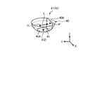
- FIG. 1 is a diagram showing an example of the overall configuration of an image processing system 1 of this embodiment.
- the image processing system 1 includes an image processing device 10 , an imaging unit 12 , a detection unit 14 and a display unit 16 .
- the image processing device 10, the imaging unit 12, the detection unit 14, and the display unit 16 are connected so as to be able to exchange data or signals.
- the image processing device 10 the imaging unit 12, the detection unit 14, and the display unit 16 are mounted on the moving body 2 as an example.
- the image processing apparatus 10 according to the first embodiment is an example that uses Visual SLAM (Simultaneous Localization and Mapping) processing.
- the mobile object 2 is an object that can move.
- the mobile object 2 is, for example, a vehicle, a flyable object (a manned airplane, an unmanned airplane (eg, UAV (Unmanned Aerial Vehicle), drone)), a robot, or the like.
- the moving object 2 is, for example, a moving object that advances through human driving operation, or a moving object that can automatically advance (autonomously advance) without human driving operation.
- Vehicles are, for example, two-wheeled vehicles, three-wheeled vehicles, and four-wheeled vehicles. In this embodiment, a case where the vehicle is a four-wheeled vehicle capable of autonomously traveling will be described as an example.
- the image processing device 10 is not limited to being mounted on the moving body 2.
- the image processing device 10 may be mounted on a stationary object.
- a stationary object is an object that is fixed to the ground.
- a stationary object is an object that cannot move or an object that is stationary with respect to the ground.
- Stationary objects are, for example, traffic lights, parked vehicles, road signs, and the like.
- the image processing apparatus 10 may be installed in a cloud server that executes processing on the cloud.
- the photographing unit 12 photographs the surroundings of the moving object 2 and acquires photographed image data.
- the photographed image data is simply referred to as a photographed image.
- the photographing unit 12 is, for example, a digital camera capable of photographing moving images. It should be noted that photographing refers to converting an image of a subject formed by an optical system such as a lens into an electrical signal.
- the photographing unit 12 outputs the photographed image to the image processing device 10 . Also, in the present embodiment, the description will be made on the assumption that the photographing unit 12 is a monocular fisheye camera (for example, the viewing angle is 195 degrees).
- imaging units 12 imaging units 12A to 12D
- a plurality of photographing units 12 photograph subjects in respective photographing areas E (photographing areas E1 to E4) to obtain photographed images.
- the photographing directions of the plurality of photographing units 12 are different from each other. Further, it is assumed that the photographing directions of the plurality of photographing units 12 are adjusted in advance so that at least a part of the photographing area E overlaps between adjacent photographing units 12 .
- the four imaging units 12A to 12D are an example, and the number of imaging units 12 is not limited.
- the moving body 2 has a vertically long shape such as a bus or a truck
- a total of six imaging units 12 can be used by arranging the imaging units 12 one by one. That is, depending on the size and shape of the moving body 2, the number and arrangement positions of the imaging units 12 can be arbitrarily set.
- the process of determining the boundary angle which will be described later, can be realized by providing at least two imaging units 12 .
- the detection unit 14 detects position information of each of a plurality of detection points around the moving object 2 . In other words, the detection unit 14 detects the position information of each detection point in the detection area F.
- FIG. A detection point indicates each point individually observed by the detection unit 14 in the real space.
- a detection point corresponds to, for example, a three-dimensional object around the moving object 2 .
- the position information of the detection point is information that indicates the position of the detection point in real space (three-dimensional space).
- the position information of the detection point is information indicating the distance from the detection unit 14 (that is, the position of the moving body 2) to the detection point and the direction of the detection point with respect to the detection unit 14.
- FIG. These distances and directions can be represented, for example, by position coordinates indicating the relative positions of the detection points with respect to the detection unit 14, position coordinates indicating the absolute positions of the detection points, vectors, or the like.
- the detection unit 14 is, for example, a 3D (Three-Dimensional) scanner, a 2D (Two-Dimensional) scanner, a distance sensor (millimeter wave radar, laser sensor), a sonar sensor that detects an object with sound waves, an ultrasonic sensor, and the like.
- the laser sensor is, for example, a three-dimensional LiDAR (Laser Imaging Detection and Ranging) sensor.
- the detection unit 14 may be a device using SfM (Structure from Motion) technology for measuring the distance from an image captured by a monocular camera.
- a plurality of imaging units 12 may be used as the detection unit 14 .
- one of the multiple imaging units 12 may be used as the detection unit 14 .
- the display unit 16 displays various information.
- the display unit 16 is, for example, an LCD (Liquid Crystal Display) or an organic EL (Electro-Luminescence) display.
- the image processing device 10 is communicably connected to an electronic control unit (ECU: Electronic Control Unit) 3 mounted on the mobile object 2 .
- the ECU 3 is a unit that electronically controls the moving body 2 .
- the image processing apparatus 10 is capable of receiving CAN (Controller Area Network) data such as the speed and moving direction of the moving body 2 from the ECU 3 .
- CAN Controller Area Network
- FIG. 2 is a diagram showing an example of the hardware configuration of the image processing device 10. As shown in FIG.
- the image processing apparatus 10 includes a CPU (Central Processing Unit) 10A, a ROM (Read Only Memory) 10B, a RAM (Random Access Memory) 10C, and an I/F (Interface) 10D, and is, for example, a computer.
- the CPU 10A, ROM 10B, RAM 10C, and I/F 10D are interconnected by a bus 10E, and have a hardware configuration using a normal computer.
- the CPU 10A is an arithmetic device that controls the image processing device 10.
- CPU 10A corresponds to an example of a hardware processor.
- the ROM 10B stores programs and the like for realizing various processes by the CPU 10A.
- the RAM 10C stores data required for various processes by the CPU 10A.
- the I/F 10D is an interface for connecting to the imaging unit 12, the detection unit 14, the display unit 16, the ECU 3, and the like, and for transmitting and receiving data.
- a program for executing image processing executed by the image processing apparatus 10 of the present embodiment is pre-installed in the ROM 10B or the like and provided.
- the program executed by the image processing apparatus 10 of the present embodiment may be configured to be provided by being recorded on a recording medium in the form of a file in a format installable or executable in the image processing apparatus 10 .
- a recording medium is a computer-readable medium. Recording media include CD (Compact Disc)-ROM, flexible disk (FD), CD-R (Recordable), DVD (Digital Versatile Disk), USB (Universal Serial Bus) memory, SD (Secure Digital) card, and the like.
- the image processing device 10 simultaneously estimates the position information of the detection point and the self-position information of the moving body 2 from the captured image captured by the imaging unit 12 by Visual SLAM processing.
- the image processing device 10 joins together a plurality of spatially adjacent captured images to generate and display a composite image that provides a bird's-eye view of the surroundings of the moving body 2 .
- the imaging unit 12 is used as the detection unit 14 in this embodiment.
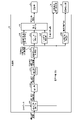
- FIG. 3 is a diagram showing an example of the functional configuration of the image processing device 10. As shown in FIG. In addition to the image processing device 10, FIG. 3 also shows the photographing unit 12 and the display unit 16 in order to clarify the data input/output relationship.
- the image processing apparatus 10 includes an acquisition unit 20, a selection unit 23, a Visual-SLAM processing unit 24 (hereinafter referred to as "VSLAM processing unit 24"), a determination unit 30, a deformation unit 32, and a virtual viewpoint line of sight determination unit.
- VSLAM processing unit 24 Visual-SLAM processing unit 24
- a unit 34 a projection conversion unit 36 , and an image synthesis unit 38 are provided.
- a part or all of the plurality of units may be realized by, for example, causing a processing device such as the CPU 10A to execute a program, that is, by software. Also, some or all of the plurality of units may be realized by hardware such as an IC (Integrated Circuit), or may be realized by using software and hardware together.
- a processing device such as the CPU 10A to execute a program
- a program that is, by software.
- some or all of the plurality of units may be realized by hardware such as an IC (Integrated Circuit), or may be realized by using software and hardware together.
- the acquisition unit 20 acquires the captured image from the imaging unit 12.
- the obtaining unit 20 obtains a captured image from each of the imaging units 12 (imaging units 12A to 12D).
- the acquisition unit 20 outputs the acquired captured image to the projection conversion unit 36 and the selection unit 23 every time it acquires a captured image.
- the selection unit 23 selects the detection area of the detection point.
- the selection unit 23 selects a detection region by selecting at least one imaging unit 12 from among the plurality of imaging units 12 (imaging units 12A to 12D).
- the selection unit 23 uses the vehicle state information and the detection direction information included in the CAN data received from the ECU 3, or the instruction information input by the user's operation instruction to select at least one of the photographing units. Select 12.
- the vehicle state information is, for example, information indicating the traveling direction of the moving body 2, the state of the direction indication of the moving body 2, the state of the gear of the moving body 2, and the like. Vehicle state information can be derived from CAN data.
- the detection direction information is information indicating the direction in which the information of interest is detected, and can be derived by POI (Point Of Interest) technology.
- the instruction information is information indicating a direction in which attention should be paid, and is input by a user's operation instruction.
- the selection unit 23 selects the direction of the detection area using the vehicle state information. Specifically, the selection unit 23 uses the vehicle state information to specify parking information such as rear parking information indicating rear parking of the moving body 2 and parallel parking information indicating parallel parking.
- the selection unit 23 associates the parking information with the identification information of any one of the imaging units 12 and stores them in advance. For example, the selection unit 23 stores in advance the identification information of the photographing unit 12D (see FIG. 1) that photographs the rear of the moving body 2 in association with the rear parking information. In addition, the selection unit 23 stores in advance identification information of each of the image capturing units 12B and 12C (see FIG. 1) that capture images of the moving body 2 in the horizontal direction in association with the parallel parking information.
- the selection unit 23 selects the direction of the detection area by selecting the imaging unit 12 corresponding to the parking information derived from the received vehicle state information.
- the selection unit 23 may select the imaging unit 12 having the imaging area E in the direction indicated by the detection direction information. Further, the selection unit 23 may select the imaging unit 12 having the imaging area E in the direction indicated by the detection direction information derived by the POI technique.
- the selection unit 23 outputs, to the VSLAM processing unit 24 , the selected image captured by the image capturing unit 12 among the captured images acquired by the acquisition unit 20 .
- the VSLAM processing unit 24 executes Visual SLAM processing using the captured image received from the selection unit 23 to generate environment map information, and outputs the generated environment map information to the determination unit 30 .
- the VSLAM processing unit 24 includes a matching unit 25, a storage unit 26, a self-position estimation unit 27, a correction unit 28, and a three-dimensional reconstruction unit 29.
- the matching unit 25 performs feature amount extraction processing and matching processing between images for a plurality of captured images with different capturing timings (a plurality of captured images with different frames). Specifically, the matching unit 25 performs feature quantity extraction processing from these multiple captured images. The matching unit 25 performs a matching process of identifying corresponding points between the plurality of captured images by using feature amounts between the plurality of captured images captured at different timings. The matching section 25 outputs the matching processing result to the self-position estimation section 27 .
- the self-position estimation unit 27 uses a plurality of matching points acquired from the matching unit 25 to estimate the self-position relative to the captured image by projective transformation or the like.
- the self-position includes information on the position (three-dimensional coordinates) and inclination (rotation) of the photographing unit 12, and the self-position estimation unit 27 stores this as self-position information in the environment map information 26A.
- the three-dimensional reconstruction unit 29 performs perspective projection conversion processing using the movement amount (translation amount and rotation amount) of the self-position estimated by the self-position estimation unit 27, and the three-dimensional coordinates of the matching point (relative to the self-position coordinates).
- the three-dimensional reconstruction unit 29 stores the determined three-dimensional coordinates in the environmental map information 26A as peripheral position information.
- the storage unit 26 stores various data.
- the storage unit 26 is, for example, a RAM, a semiconductor memory device such as a flash memory, a hard disk, an optical disk, or the like.
- the storage unit 26 may be a storage device provided outside the image processing apparatus 10 .
- the storage unit 26 may be a storage medium. Specifically, the storage medium may store or temporarily store programs and various types of information downloaded via a LAN (Local Area Network), the Internet, or the like.
- LAN Local Area Network
- the environment map information 26A is information in which the peripheral position information calculated by the three-dimensional reconstruction unit 29 and the self-position information calculated by the self-position estimation unit 27 are registered in a three-dimensional coordinate space with a predetermined position in the real space as the origin. .
- the predetermined position in the real space may be determined, for example, based on preset conditions.
- the predetermined position is the position of the moving body 2 when the image processing device 10 executes the image processing of this embodiment.
- the image processing apparatus 10 may set the position of the moving body 2 when it is determined that the predetermined timing is reached as the predetermined position.
- the image processing device 10 may determine that the predetermined timing has been reached when it determines that the behavior of the moving body 2 indicates a parking scene.
- the behavior indicating the parking scene is, for example, when the speed of the moving body 2 becomes equal to or less than a predetermined speed, when the gear of the moving body 2 is put into the reverse gear, or the like, a signal indicating the start of parking is received by an operation instruction of the user.
- a predetermined speed is not limited to the parking scene.
- FIG. 4 is a schematic diagram of an example of the environment map information 26A.
- the environmental map information 26A includes positional information (peripheral positional information) of each detection point P and self-positional information of the self-position S of the moving body 2, which corresponds in the three-dimensional coordinate space. It is information registered at the coordinate position to be used.
- self-positions S of self-position S1 to self-position S3 are shown.
- a larger numerical value following S means that the self-position S is closer to the current timing.
- the correction unit 28 calculates the sum of distance differences in the three-dimensional space between the three-dimensional coordinates calculated in the past and the newly calculated three-dimensional coordinates for points matched multiple times between a plurality of frames. is minimized, the peripheral location information and self-location information registered in the environmental map information 26A are corrected using, for example, the method of least squares. Note that the correction unit 28 may correct the movement amount (translation amount and rotation amount) of the self-position used in the process of calculating the self-position information and the peripheral position information.
- the timing of correction processing by the correction unit 28 is not limited.
- the correction unit 28 may perform the above correction process at predetermined timings.
- the predetermined timing may be determined, for example, based on preset conditions.
- the image processing apparatus 10 will be described as an example in which the correction unit 28 is provided. However, the image processing apparatus 10 may be configured without the correction section 28 .
- the determination unit 30 receives the environment map information from the VSLAM processing unit 24, and uses the surrounding position information and self-position information accumulated in the environment map information 26A to calculate the measured distance between the moving object 2 and surrounding three-dimensional objects.
- the measured distance means the distance between objects measured by processing using a distance sensor or an image (VSLAM processing in this embodiment). Since the measured distance is a distance obtained by processing using a distance sensor or an image, it can take any value depending on the situation. In that sense, the measured distance is a continuous value.
- the determination unit 30 executes distance stabilization processing for converting the measured distance into a stabilized distance.
- the stabilized distance means a discrete distance (non-continuous value) obtained based on the measured distance. This distance stabilization processing will be described later in detail. Note that the determination unit 30 is an example of a conversion unit.
- the determination unit 30 determines the projection shape of the projection plane using the stabilized distance obtained by the distance stabilization process, and generates projection shape information.
- the determining unit 30 outputs the generated projection shape information to the transforming unit 32 .
- the projection plane is a three-dimensional plane for projecting the peripheral image of the moving object 2.
- the peripheral image of the moving body 2 is a captured image of the periphery of the moving body 2, and is a captured image captured by each of the imaging units 12A to 12D.
- the projected shape on the projection plane is a three-dimensional (3D) shape that is virtually formed in a virtual space corresponding to the real space.
- the determination of the projection shape of the projection plane executed by the determination unit 30 is called projection shape determination processing.
- the determination unit 30 calculates an asymptotic curve of the surrounding position information with respect to the self position using the surrounding position information of the moving body 2 and the self-position information accumulated in the environment map information 26A.
- FIG. 5 is an explanatory diagram of the asymptotic curve Q generated by the determining unit 30.
- the asymptotic curve is an asymptotic curve of a plurality of detection points P in the environmental map information 26A.
- FIG. 5 is an example showing an asymptotic curve Q in a projection image obtained by projecting a photographed image onto a projection plane when the moving body 2 is viewed from above.
- the determination unit 30 has identified three detection points P in order of proximity to the self-position S of the mobile object 2 .
- the determination unit 30 generates an asymptotic curve Q for these three detection points P.
- the determination unit 30 outputs the self-position and the asymptotic curve information to the virtual viewpoint line-of-sight determination unit 34 .
- the configuration of the determination unit 30 will be explained later in detail.
- the transformation unit 32 transforms the projection plane based on the projection shape information received from the determination unit 30.
- FIG. 6 is a schematic diagram showing an example of the reference projection plane 40.
- FIG. FIG. 7 is a schematic diagram showing an example of the projection shape 41 determined by the determination unit 30.
- the transforming unit 32 transforms the pre-stored reference projection plane shown in FIG. 6 based on the projection shape information, and determines the transformed projection plane 42 as the projection shape 41 shown in FIG.
- the determination unit 30 generates modified projection plane information based on the projection shape 41 .
- This deformation of the reference projection plane is performed, for example, using the detection point P closest to the moving object 2 as a reference.
- the deformation section 32 outputs the deformation projection plane information to the projection conversion section 36 .
- the transforming unit 32 transforms the reference projection plane into a shape along an asymptotic curve of a predetermined number of detection points P in order of proximity to the moving body 2 based on the projection shape information.
- the virtual viewpoint line-of-sight determination unit 34 determines virtual viewpoint line-of-sight information based on the self-position and the asymptotic curve information.
- the virtual viewpoint line-of-sight determining unit 34 determines, for example, a direction passing through the detection point P closest to the self-position S of the moving body 2 and perpendicular to the modified projection plane as the line-of-sight direction. Further, the virtual viewpoint line-of-sight determination unit 34 fixes the direction of the line-of-sight direction L, for example, and sets the coordinates of the virtual viewpoint O to an arbitrary Z coordinate and an arbitrary Z coordinate in the direction away from the asymptotic curve Q toward the self-position S. Determined as XY coordinates.
- the XY coordinates may be coordinates of a position farther from the asymptotic curve Q than the self-position S.
- the virtual viewpoint line-of-sight determination unit 34 outputs virtual viewpoint line-of-sight information indicating the virtual viewpoint O and the line-of-sight direction L to the projection conversion unit 36 .
- the line-of-sight direction L may be a direction from the virtual viewpoint O to the position of the vertex W of the asymptotic curve Q.
- the projection conversion unit 36 generates a projection image by projecting the photographed image acquired from the photographing unit 12 onto the deformed projection plane based on the deformed projection plane information and the virtual viewpoint line-of-sight information.
- the projection conversion unit 36 converts the generated projection image into a virtual viewpoint image and outputs the virtual viewpoint image to the image synthesis unit 38 .
- a virtual viewpoint image is an image of a projected image viewed in an arbitrary direction from a virtual viewpoint.
- the projection image generation processing by the projection conversion unit 36 will be described in detail with reference to FIG.
- the projection conversion unit 36 projects the captured image onto the modified projection plane 42 .
- the projection conversion unit 36 generates a virtual viewpoint image, which is an image of the photographed image projected onto the modified projection plane 42 viewed in the line-of-sight direction L from an arbitrary virtual viewpoint O (not shown).
- the position of the virtual viewpoint O may be the latest self-position S of the moving body 2, for example.
- the XY coordinate values of the virtual viewpoint O may be set to the XY coordinate values of the latest self-position S of the moving object 2 .
- the value of the Z coordinate (position in the vertical direction) of the virtual viewpoint O may be the value of the Z coordinate of the detection point P closest to the self-position S of the moving body 2 .
- the line-of-sight direction L may be determined, for example, based on a predetermined criterion.
- the line-of-sight direction L may be, for example, the direction from the virtual viewpoint O toward the detection point P closest to the self-position S of the moving object 2 . Also, the line-of-sight direction L may be a direction that passes through the detection point P and is perpendicular to the modified projection plane 42 .
- the virtual viewpoint line-of-sight information indicating the virtual viewpoint O and the line-of-sight direction L is created by the virtual viewpoint line-of-sight determination unit 34 .
- the virtual viewpoint line-of-sight determination unit 34 may determine the line-of-sight direction L as a direction that passes through the detection point P closest to the self-position S of the moving body 2 and that is perpendicular to the modified projection plane 42 .
- the virtual viewpoint line-of-sight determination unit 34 fixes the direction of the line-of-sight direction L, and sets the coordinates of the virtual viewpoint O to an arbitrary Z coordinate and an arbitrary XY coordinate in the direction away from the asymptotic curve Q toward the self-position S. may be determined as In that case, the XY coordinates may be coordinates of a position farther from the asymptotic curve Q than the self-position S.
- the virtual viewpoint line-of-sight determination unit 34 outputs virtual viewpoint line-of-sight information indicating the virtual viewpoint O and the line-of-sight direction L to the projection conversion unit 36 .
- the line-of-sight direction L may be a direction from the virtual viewpoint O to the position of the vertex W of the asymptotic curve Q.
- the projection conversion unit 36 receives virtual viewpoint line-of-sight information from the virtual viewpoint line-of-sight determination unit 34 .
- the projection conversion unit 36 identifies the virtual viewpoint O and the line-of-sight direction L by receiving the virtual viewpoint line-of-sight information. Then, the projection conversion unit 36 generates a virtual viewpoint image, which is an image viewed in the line-of-sight direction L from the virtual viewpoint O, from the photographed image projected onto the modified projection plane 42 .
- the projective transformation unit 36 outputs the virtual viewpoint image to the image synthesizing unit 38 .
- the image composition unit 38 generates a composite image by extracting part or all of the virtual viewpoint image.
- the image synthesizing unit 38 performs a process of joining a plurality of virtual viewpoint images (here, four virtual viewpoint images corresponding to the photographing units 12A to 12D) in the boundary area between the photographing units.
- the image composition unit 38 outputs the generated composite image to the display unit 16.
- the synthesized image may be a bird's-eye view image with a virtual viewpoint O above the mobile object 2, or an image in which the virtual viewpoint O is inside the mobile object 2 and the mobile object 2 is displayed semi-transparently.
- the projection conversion unit 36 and the image synthesizing unit 38 constitute an image generation unit 37 .
- FIG. 8 is a schematic diagram showing an example of the configuration of the determination unit 30.
- the determination unit 30 includes an absolute distance conversion unit 30A, an extraction unit 30B, a nearest neighbor identification unit 30C, a distance stabilization processing unit 30I, a reference projection plane shape selection unit 30D, a scale It includes a determination unit 30E, an asymptotic curve calculation unit 30F, a shape determination unit 30G, and a boundary area determination unit 30H.
- the absolute distance conversion unit 30A converts the relative positional relationship between the self-position and the surrounding three-dimensional objects, which can be known from the environment map information 26A, into the absolute value of the distance from the self-position to the surrounding three-dimensional objects.
- the speed data of the mobile object 2 included in the CAN data received from the ECU 3 of the mobile object 2 is used.
- the relative positional relationship between the self-position S and the plurality of detection points P is known, but the absolute value of the distance is not calculated.
- the distance between the self-position S3 and the self-position S2 can be obtained from the frame-to-frame cycle for calculating the self-position and the speed data during the interval based on the CAN data. Since the relative positional relationship of the environment map information 26A is similar to the real space, knowing the distance between the self-position S3 and the self-position S2 allows the distance from the self-position S to all other detection points P to be detected.
- the absolute value of the distance (measured distance) can also be determined.
- the absolute distance conversion unit 30A may be omitted.
- the absolute distance conversion unit 30A outputs the calculated measured distance of each of the plurality of detection points P to the extraction unit 30B. Further, the absolute distance conversion unit 30A outputs the calculated current position of the moving object 2 to the virtual viewpoint line of sight determination unit 34 as self-position information of the moving object 2 .
- the extraction unit 30B extracts detection points P existing within a specific range from among the plurality of detection points P whose measured distances are received from the absolute distance conversion unit 30A.
- the specific range is, for example, a range from the road surface on which the mobile body 2 is arranged to a height corresponding to the vehicle height of the mobile body 2 .
- the range is not limited to this range.
- the extraction unit 30B extracts the detection points P of, for example, an object that obstructs the movement of the moving body 2 or an object positioned adjacent to the moving body 2. can be done.
- the extraction unit 30B outputs the measured distance of each of the extracted detection points P to the nearest neighbor identification unit 30C.
- the nearest neighbor identification unit 30C divides the circumference of the self-position S of the moving body 2 into specific ranges (for example, angle ranges), and for each range, the closest detection point P to the moving body 2 or the closest detection point to the moving body 2. A plurality of detection points P are specified in order.
- the nearest neighbor identification unit 30C identifies the detection point P using the measured distance received from the extraction unit 30B. In the present embodiment, the nearest neighbor identifying unit 30C identifies a plurality of detection points P in order of proximity to the moving body 2 for each range as an example.
- the nearest neighbor identification unit 30C outputs the measured distance of the detection point P identified for each range to the distance stabilization processing unit 30I.
- the distance stabilization processing unit 30I executes distance stabilization processing for converting the measured distance into a stabilized distance.
- the distance stabilization processing executed by the distance stabilization processing section 30I includes first distance stabilization processing and second distance stabilization processing. Each of the first distance stabilization process and the second distance stabilization process will be described in detail below with reference to FIGS. 9 to 14.
- FIG. 9 Each of the first distance stabilization process and the second distance stabilization process will be described in detail below with reference to FIGS. 9 to 14.
- the first distance stabilization process is based on the magnitude relationship between the measured distance of the detection point P specified for each range and the threshold, and the measured distance is the first distance as the stabilized distance or the first distance It converts to a smaller second distance.
- FIG. 9 is a plan view showing an example of a situation in which the mobile body 2 is rear-parked on the parking line PL where the pillar C exists.
- FIG. 10 is a plan view showing an example of a situation in which the moving body 2 travels backward and approaches the pillar C more than in FIG.
- the distance stabilization processing when the mobile body 2 parks backward will be explained.
- the pillar C exists in the imaging area E4 of the imaging unit 12D. Therefore, the measured distances of the plurality of detection points P regarding the pillar C specified for each range are sequentially output from the nearest neighbor specifying unit 30C to the distance stabilization processing unit 30I.
- FIG. 11 is a diagram showing an example of temporal changes in the measured distance of the detection point P of the pillar C that is closest to the moving body 2.
- the circles in FIG. 11 indicate acquisition of one measurement distance.
- the measured distance d of the detection point P becomes smaller.
- the fact that the measured distance d increases from the time tr indicates that the moving body 2 has once moved forward due to the fact that the moving body 2 turns back when parking backwards.
- the measured distance d fluctuates including a slight increase or decrease in addition to the amount of change associated with backward movement of the moving body 2 in the period up to time tr , for example. do.
- This variation is due to measurement errors (fluctuations in measured values due to noise and other factors) of the measured distance obtained using the sensor (in the case of this embodiment, the measured distance obtained by Visual SLAM processing using the captured image). This is due to
- first fluctuation of the projection plane when the projection plane is deformed according to the fluctuating measurement distance d as shown in FIG. It frequently deforms in the receding direction (this phenomenon is hereinafter also referred to as "first fluctuation of the projection plane").
- first fluctuation of the projection plane when an image (projected image) projected onto a projection plane with temporal fluctuation is displayed, the projected image fluctuates and the image appears to be distorted.
- the first distance stabilization process solves such a problem that the projection image becomes unnatural due to the first fluctuation of the projection plane.
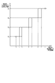
- FIG. 12 is a graph showing an example of the relationship between the input and output of the distance stabilization processing section 30I.
- the horizontal axis indicates the measured distance d which is the input of the distance stabilization processing section 30I
- the vertical axis indicates the stabilized distance D which is the output of the distance stabilization processing section 30I.
- the distance stabilization processing unit 30I keeps the measured distance d at Convert to stabilized distance D1 and output.
- the distance stabilization processing section 30I converts the measured distance d into a stabilized distance D2 and outputs it.
- the threshold d3 is an example of a first threshold as a down determination threshold (threshold for determining down of the stabilization distance).
- the stabilization distance D 1 and the stabilization distance D 2 are examples of a first distance as a stabilization distance before down and a second distance as a stabilization distance after down, respectively.
- the distance stabilization processing unit 30I stabilizes the measured distance d until it becomes smaller than the threshold d5 which is smaller than the threshold d3 after the measured distance d becomes smaller than the threshold d3 . Convert to distance D2 and output.
- the distance stabilization processing section 30I converts the measured distance d into a stabilized distance D3 and outputs it.
- the threshold d5 is an example of the third threshold as the down determination threshold.
- the stabilization distance D 2 and the stabilization distance D 3 are examples of the second distance as the stabilization distance before down and the third distance as the stabilization distance after down, respectively.
- the distance stabilization processing unit 30I converts the measured distance d into the stabilized distance D3 and outputs it until the successively input measured distance d becomes smaller than the threshold value d7 .
- the distance stabilization processing unit 30I changes the measured distance d to the stabilized distance D4 as the stabilized distance after down. converted to and output.
- the deformation section 32 deforms the projection plane using the information of the stabilization distance D, so that the fluctuation of the projection plane can be suppressed.
- the second distance stabilization process further eliminates the problem that the projection image becomes unnatural due to the temporal fluctuation of the projection plane when the first distance stabilization process is executed. That is, after the measured distance becomes smaller than the first threshold, the second distance stabilization process is based on the magnitude relationship between the acquired measured distance and the second threshold larger than the first threshold. to convert the measured distance into a first distance or a second distance.
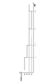
- FIG. 13 is a diagram showing an example of temporal changes in the stabilized distance D obtained by the first distance stabilization process using the measured distance d of the detection point P of the pillar C shown in FIG. 11 as an input. .
- the measured distance d in FIG. 11 including many fluctuations can be converted into a stabilized distance D with less fluctuation. Therefore, it is possible to display a stable projected image using a projection plane in which fluctuation is suppressed.
- the stabilization distance D fluctuates between D1 and D2 in the period from time t2 to time t3 .
- the stabilization distance D is between D2 and D3 in the period from time t4 to time t5 , and between D3 and D4 in the period from time t6 to time t7 .
- it fluctuates between D4 and D5 .
- Fluctuations in the stabilization distance D in each of the above periods are, for example, in the period from time t2 to time t3 shown in FIG. This is because the fluctuation of increasing and decreasing is repeated, and the stabilization distance D also fluctuates between D1 and D2 in conjunction with this fluctuation.
- the shape of the projection plane is determined according to the value of the stabilization distance D. Therefore, during the period from time t2 to time t3 corresponding to before and after the switching of the stabilization distance, the deformation of the projection plane frequently occurs in conjunction with the fluctuation of the stabilization distance D (hereinafter referred to as This phenomenon is also called "the second fluctuation of the projection plane"). As a result, the projected image that is stably displayed by the first distance stabilization process is changed from the projected image to Image disturbance occurs.
- the second distance stabilization process solves such a problem that the projection image becomes unnatural due to the second fluctuation of the projection plane.
- the distance stabilization processing unit 30I determines that the measured distance d is smaller than the threshold value d3 . does not convert the stabilization distance D to D1 , even if That is, when the measured distance d is smaller than the threshold d3 , the distance stabilization processing unit 30I sets the stabilized distance D to D1 as long as the measured distance d does not exceed the threshold d2 , which is larger than the threshold d3 . do not convert to Therefore, the dead zone is between the threshold d3 and the threshold d2 .
- the threshold d3 is an example of the first threshold as the down determination threshold.
- the threshold d2 is an example of a second threshold as an up determination threshold (threshold for determining whether the stabilization distance is increased).
- the distance stabilization processing unit 30I sets the stabilized distance D to D2 as long as the measured distance d does not exceed the threshold d4 , which is larger than the threshold d5 . do not convert to Therefore, the dead zone is between the threshold d5 and the threshold d4 .
- the threshold d5 is an example of a first threshold as a down determination threshold
- the threshold d4 is an example of a second threshold as an up determination threshold.
- the distance stabilization processing unit 30I sets the measured distance d to the threshold value d7 . Do not convert the stabilization distance D to D3 , even if it becomes greater than . That is, when the measured distance d is smaller than the threshold d7 , the distance stabilization processing unit 30I sets the stabilized distance D to D3 as long as the measured distance d does not exceed the threshold d6 , which is larger than the threshold d7 . do not convert to Therefore, the dead zone is between the threshold d7 and the threshold d6 .
- the threshold d7 is an example of a first threshold as a down determination threshold
- the threshold d6 is an example of a second threshold as an up determination threshold.
- the second distance stabilization process according to the relationship between the input and the output shown in FIG.
- the value of the stabilization distance D is determined not by the magnitude relationship with the threshold value of , but by the magnitude relationship with a second threshold value that is greater than the first threshold value. That is, the value of the stabilization distance D is controlled according to the history of the measured distance d. In that sense, the second distance stabilization process can be called a stabilization distance D hysteresis process.
- FIG. 14 is a diagram showing an example of temporal changes in the stabilized distance D obtained by the first and second distance stabilization processing using the measured distance of the detection point P of the pillar C shown in FIG. 11 as an input. is.
- the time when the stabilization distance D is converted from D1 to D2 is t'3
- the time when D2 is converted to D3 is t'5
- the stabilization distance D is converted from D3 to D4 .
- the time at which D4 is converted to D3 is t'8 .
- fluctuations in the stabilization distance D during periods before and after each down determination threshold value or up determination threshold value are eliminated.
- the dead zone defined by the thresholds d3 and d2 , the dead zone defined by the thresholds d5 and d4 , and the dead zone defined by the thresholds d7 and d6 are respectively different lengths. This is because the accuracy of the distance sensor (the VSLAM processing unit 24 in this case) varies depending on the measured distance from the moving body 2 to the three-dimensional object.
- the width of each of these dead zones can be arbitrarily set by adjusting each threshold according to the measurement accuracy of the distance sensor. For example, if the measurement accuracy of the distance sensor is ⁇ 5% of the absolute distance, the width of the dead zone may be set to increase as the measured distance d increases, as in the example shown in FIG. .
- the distance stabilization processing unit 30I changes the measured distance d to the threshold value d5 as the moving object 2 travels backward. If so, the stabilization distance D will be converted to D3 according to the first distance stabilization process.
- the thresholds d 3 and d 5 are examples of the first and third thresholds, respectively, and the stabilization distances D 2 and D 3 are examples of the second and third distances, respectively. be.
- the distance stabilization processing unit 30I applies the stabilization distance of the detection point P specified for each range obtained by the distance stabilization processing to the reference projection plane shape selection unit 30D, the scale determination unit 30E, the asymptotic curve calculation unit 30F, It is output to the boundary area determining section 30H.
- the reference projection plane shape selection unit 30D selects the shape of the reference projection plane.
- the reference projection plane 40 is, for example, a projection plane having a shape that serves as a reference when changing the shape of the projection plane.
- the shape of the reference projection plane 40 is, for example, a bowl shape, a cylinder shape, or the like. Note that FIG. 6 illustrates a bowl-shaped reference projection plane 40 .
- a bowl shape is a shape having a bottom surface 40A and a side wall surface 40B, one end of the side wall surface 40B continuing to the bottom surface 40A, and the other end being open.
- the side wall surface 40B increases in horizontal cross-sectional width from the bottom surface 40A side toward the opening side of the other end.
- the bottom surface 40A is circular, for example.
- the circular shape includes a perfect circular shape and a circular shape other than a perfect circular shape such as an elliptical shape.
- a horizontal section is an orthogonal plane perpendicular to the vertical direction (direction of arrow Z).
- the orthogonal plane is a two-dimensional plane along an arrow X direction orthogonal to the arrow Z direction and an arrow Y direction orthogonal to the arrow Z direction and the arrow X direction.
- the horizontal section and the orthogonal plane may be hereinafter referred to as the XY plane.
- the bottom surface 40A may have a shape other than a circular shape, such as an oval shape.
- a cylindrical shape is a shape consisting of a circular bottom surface 40A and side wall surfaces 40B that are continuous with the bottom surface 40A.
- the side wall surface 40B forming the cylindrical reference projection plane 40 has a cylindrical shape with one end opening continuing to the bottom surface 40A and the other end being open.
- the side wall surface 40B forming the cylindrical reference projection plane 40 has a shape whose diameter in the XY plane is substantially constant from the bottom surface 40A side toward the opening side of the other end.
- the bottom surface 40A may have a shape other than a circular shape, such as an oval shape.
- the reference projection plane 40 is a three-dimensional model that is virtually formed in a virtual space in which the bottom surface 40A substantially coincides with the road surface below the moving body 2 and the center of the bottom surface 40A is the self-position S of the moving body 2. be.
- the reference projection plane shape selection unit 30D selects the shape of the reference projection plane 40 by reading one specific shape from a plurality of types of reference projection planes 40 .
- the reference projection plane shape selection unit 30D selects the shape of the reference projection plane 40 based on the positional relationship between the self-position and surrounding three-dimensional objects, the stabilization distance, and the like. It should be noted that the shape of the reference projection plane 40 may be selected by a user's operation instruction.
- the reference projection plane shape selection section 30D outputs the determined shape information of the reference projection plane 40 to the shape determination section 30G. In this embodiment, as described above, the reference projection plane shape selection unit 30D selects the bowl-shaped reference projection plane 40 as an example.
- the scale determination unit 30E determines the scale of the reference projection plane 40 having the shape selected by the reference projection plane shape selection unit 30D.
- the scale determination unit 30E determines, for example, to reduce the scale when there are a plurality of detection points P within a predetermined distance range from the self-position S.
- the scale determining section 30E outputs scale information of the determined scale to the shape determining section 30G.
- the asymptotic curve calculation unit 30F uses each of the stabilization distances of the detection points P closest to the self-position S for each range from the self-position S received from the nearest neighbor identification unit 30C to determine the asymptotic curve of the calculated asymptotic curve Q.
- the curve information is output to the shape determination section 30G and the virtual viewpoint line of sight determination section 34 .
- the asymptotic curve calculation unit 30F may calculate the asymptotic curve Q of the detection points P accumulated for each of a plurality of portions of the reference projection plane 40 . Then, the asymptotic curve calculation unit 30F may output the calculated asymptotic curve information of the asymptotic curve Q to the shape determination unit 30G and the virtual viewpoint line of sight determination unit 34 .
- the shape determination unit 30G enlarges or reduces the reference projection plane 40 having the shape indicated by the shape information received from the reference projection plane shape selection unit 30D to the scale of the scale information received from the scale determination unit 30E. Then, the shape determination unit 30G transforms the reference projection plane 40 after being enlarged or reduced so as to conform to the asymptotic curve information of the asymptotic curve Q received from the asymptotic curve calculation unit 30F, and determines the projection shape. Determined as
- the shape determining unit 30G deforms the reference projection plane 40 into a shape passing through the detection point P closest to the self-position S of the moving body 2, which is the center of the bottom surface 40A of the reference projection plane 40.
- the shape is determined as projected shape 41 .
- the shape passing through the detection point P means that the side wall surface 40B after deformation has a shape passing through the detection point P.
- the self-position S is the latest self-position S calculated by the self-position estimator 27 .
- the shape determination unit 30G adjusts the bottom surface so that when the reference projection plane 40 is deformed, a partial region of the side wall surface 40B becomes a wall surface passing through the detection point P closest to the moving body 2.
- a deformed shape of a partial region of 40A and side wall surface 40B is determined as a projected shape 41 .
- the projected shape 41 after deformation is, for example, a shape raised from a rising line 44 on the bottom surface 40A in a direction approaching the center of the bottom surface 40A from the viewpoint of the XY plane (planar view).
- Raising means, for example, moving part of the side wall surface 40B and the bottom surface 40A closer to the center of the bottom surface 40A so that the angle between the side wall surface 40B and the bottom surface 40A of the reference projection plane 40 becomes smaller. It means to bend or fold in a direction. In the raised shape, the raised line 44 may be positioned between the bottom surface 40A and the side wall surface 40B, and the bottom surface 40A may remain undeformed.
- the shape determination unit 30G determines to deform the specific area on the reference projection plane 40 so as to protrude to a position passing through the detection point P from the viewpoint of the XY plane (planar view). The shape and range of the specific area may be determined based on predetermined criteria. Then, the shape determination unit 30G deforms the reference projection plane 40 so that the distance from the self-position S continuously increases from the protruded specific region toward regions other than the specific region on the side wall surface 40B. It is determined to have a shape that
- the projection shape 41 it is preferable to determine the projection shape 41 so that the shape of the outer circumference of the cross section along the XY plane is curved.
- the shape of the outer periphery of the cross section of the projection shape 41 is, for example, a circular shape, it may be a shape other than a circular shape.
- the shape determination unit 30G may determine, as the projection shape 41, a shape obtained by deforming the reference projection plane 40 so as to follow an asymptotic curve.
- the shape determination unit 30G generates an asymptotic curve of a predetermined number of detection points P in a direction away from the detection point P closest to the self-position S of the moving body 2 .
- the number of detection points P may be plural.
- the number of detection points P is preferably three or more.
- the shape determination unit 30G preferably generates an asymptotic curve of a plurality of detection points P located at positions separated from the self-position S by a predetermined angle or more.
- the shape determination unit 30G can determine, as the projection shape 41, a shape obtained by deforming the reference projection plane 40 so as to follow the generated asymptotic curve Q. .
- the shape determination unit 30G divides the circumference of the self-position S of the moving body 2 into specific ranges, and for each range, the closest detection point P to the moving body 2, or a plurality of detection points in order of proximity to the moving body 2 A detection point P may be specified. Then, the shape determining unit 30G transforms the reference projection plane 40 into a shape passing through the detection points P specified for each range or a shape along the asymptotic curve Q of the specified plurality of detection points P, A projection shape 41 may be determined.
- the shape determination unit 30G outputs projection shape information of the determined projection shape 41 to the deformation unit 32.
- FIG. 15 is a flowchart showing an example of the flow of image processing executed by the image processing apparatus 10.
- the acquisition unit 20 acquires the captured image from the imaging unit 12 (step S10). In addition, the acquiring unit 20 acquires the directly specified content (for example, the gear of the moving body 2 is changed to the reverse gear, etc.) and the vehicle state (eg, stopped state, etc.).
- the directly specified content for example, the gear of the moving body 2 is changed to the reverse gear, etc.
- the vehicle state eg, stopped state, etc.
- the selection unit 23 selects at least two of the imaging units 12A to 12D (step S12).
- the matching unit 25 extracts feature amounts and performs matching processing using a plurality of captured images selected in step S12 and captured by the capturing unit 12 at different capturing timings from among the captured images acquired in step S10 (step S14).
- the self-position estimation unit 27 reads the environment map information 26A (surrounding position information and self-position information) (step S16).
- the self-position estimation unit 27 uses the plurality of matching points acquired from the matching unit 25 to estimate the self-position relative to the captured image by projective transformation or the like (step S18). It is registered in the environment map information 26A (step S20).
- the three-dimensional reconstruction unit 29 reads the environmental map information 26A (surrounding position information and self-position information) (step S22).
- the three-dimensional reconstruction unit 29 performs perspective projection conversion processing using the movement amount (translation amount and rotation amount) of the self-position estimated by the self-position estimation unit 27, and the three-dimensional coordinates of the matching point (relative to the self-position coordinates) are determined and registered in the environment map information 26A as peripheral position information (step S24).
- the correction unit 28 reads the environmental map information 26A (surrounding position information and self-position information).
- the correction unit 28 calculates the sum of distance differences in the three-dimensional space between the three-dimensional coordinates calculated in the past and the newly calculated three-dimensional coordinates for points matched multiple times between a plurality of frames. is minimized, the surrounding position information and self-position information registered in the environmental map information 26A are corrected (step S26) using, for example, the method of least squares, and the environmental map information 26A is updated.
- the absolute distance conversion unit 30A takes in the speed data (vehicle speed) of the mobile object 2 included in the CAN data received from the ECU 3 of the mobile object 2.
- the absolute distance conversion unit 30A uses the speed data of the moving body 2 to convert the surrounding position information included in the environment map information 26A from the current position, which is the latest self-position S of the moving body 2, to the plurality of detection points P. It is converted into distance information to each (step S28).
- the absolute distance conversion unit 30A outputs the calculated distance information of each of the plurality of detection points P to the extraction unit 30B. Further, the absolute distance conversion unit 30A outputs the calculated current position of the moving object 2 to the virtual viewpoint line of sight determination unit 34 as self-position information of the moving object 2 .
- the extraction unit 30B extracts detection points P existing within a specific range from among the plurality of detection points P for which distance information has been received (step S30).
- the nearest neighbor identification unit 30C divides the surroundings of the self-position S of the moving body 2 into specific ranges, and for each range, a detection point P closest to the moving body 2, or a plurality of detection points in order of proximity to the moving body 2 Identify P and extract the distance to the closest object (step S32).
- the nearest neighbor specifying unit 30C outputs the measured distance (measured distance between the moving body 2 and the nearest neighbor object) d of the detection point P specified for each range to the distance stabilization processing unit 30I.
- the distance stabilization processing unit 30I receives as input the measured distance d of the detection point P specified for each range, performs the first distance stabilization processing and the second distance stabilization processing, and converts the stabilized distance D into the reference projection. Output to the surface shape selection unit 30D, the scale determination unit 30E, the asymptotic curve calculation unit 30F, and the boundary area determination unit 30H (step S33).
- the asymptotic curve calculation unit 30F calculates an asymptotic curve (step S34) and outputs it to the shape determination unit 30G and the virtual viewpoint line of sight determination unit 34 as asymptotic curve information.
- the reference projection plane shape selection unit 30D selects the shape of the reference projection plane 40 (step S36), and outputs the shape information of the selected reference projection plane 40 to the shape determination unit 30G.
- the scale determination unit 30E determines the scale of the reference projection plane 40 of the shape selected by the reference projection plane shape selection unit 30D (step S38), and outputs scale information of the determined scale to the shape determination unit 30G.
- the shape determination unit 30G determines a projection shape for how to transform the shape of the reference projection plane based on the scale information and the asymptotic curve information (step S40).
- the shape determination unit 30G outputs projection shape information of the determined projection shape 41 to the deformation unit 32 .
- the transforming unit 32 transforms the shape of the reference projection plane based on the projection shape information (step S42).
- the transformation unit 32 outputs the transformed projection plane information to the projection transformation unit 36 .
- the virtual viewpoint line-of-sight determination unit 34 determines virtual viewpoint line-of-sight information based on the self-position and the asymptotic curve information (step S44).
- the virtual viewpoint line-of-sight determination unit 34 outputs virtual viewpoint line-of-sight information indicating the virtual viewpoint O and the line-of-sight direction L to the projection conversion unit 36 .
- the projection conversion unit 36 generates a projection image by projecting the photographed image acquired from the photographing unit 12 onto the deformed projection plane based on the deformed projection plane information and the virtual viewpoint line-of-sight information.
- the projection conversion unit 36 converts the generated projection image into a virtual viewpoint image (step S46) and outputs the virtual viewpoint image to the image composition unit 38 .
- the boundary area determination unit 30H determines the boundary area based on the distance to the closest object specified for each range. That is, the boundary area determination unit 30H determines a boundary area as a superimposition area of spatially adjacent peripheral images based on the position of the object closest to the moving body 2 (step S48). Boundary area determining section 30H outputs the determined boundary area to image synthesizing section 38 .
- the image composition unit 38 generates a composite image by connecting spatially adjacent perspective projection images using the boundary area (step S50). That is, the image synthesizing unit 38 joins the perspective projection images in the four directions according to the boundary area set to the angle of the nearest object direction to generate a synthetic image. Note that spatially adjacent perspective projection images are blended at a predetermined ratio in the boundary region.
- the display unit 16 displays the composite image (step S52).
- the image processing device 10 determines whether or not to end the image processing (step S54). For example, the image processing device 10 makes the determination in step S54 by determining whether or not a signal indicating that the moving body 2 should stop moving has been received from the ECU 3 . Further, for example, the image processing apparatus 10 may make the determination in step S54 by determining whether or not an instruction to end image processing has been received by an operation instruction or the like from the user.
- step S54 If a negative determination is made in step S54 (step S54: No), the processes from step S10 to step S54 are repeatedly executed.
- step S54 Yes
- step S54 when the process returns from step S54 to step S10 after executing the correction process in step S26, the subsequent correction process in step S26 may be omitted. Further, when the process returns from step S54 to step S10 without executing the correction process of step S26, the subsequent correction process of step S26 may be executed.
- the image processing apparatus 10 includes the determining section 30 as a converting section and the transforming section 32 .
- the determination unit 30 sets the measured distance as the stabilization distance to the first distance or the first distance. Convert to a second distance that is less than .
- the deformation unit 32 deforms the projection plane of the peripheral image of the moving body 2 based on the stabilization distance.
- the deformation unit 32 deforms the projection plane of the peripheral image of the moving body 2 based on the stabilization distance with less fluctuation. As a result, it is possible to suppress the temporal fluctuation of the projection plane and eliminate the problem that the projected image becomes unnatural.
- the determination unit 30 converts the measured distance into a second distance as a stabilization distance based on the magnitude relationship between the measured distance and the first threshold, and sets a second threshold that is greater than the measured distance and the first threshold. , the measured distance is converted into a first distance as a stabilization distance.
- the determining unit 30 sets the measured distance as the stabilization distance based on the magnitude relationship between the measured distance and a third threshold smaller than the first threshold. or a third distance that is less than the second distance.
- the transforming unit 32 transforms the projection plane of the peripheral image of the moving body 2 based on the second distance or the third distance obtained by converting the measured distance.
- the distance stabilization processing unit 30I Convert the distance d to the stabilization distance D4 and output it.
- the distance stabilization processing unit 30I converts the measured distance d into a stabilized distance D3 and outputs it.
- the distance stabilization processing unit 30I after the measured distance d becomes larger than the threshold value d6 and converts the stabilized distance D into D3 , the measured distance d becomes equal to the threshold value d6 . Do not convert the stabilization distance D to D 4 unless it falls below a threshold d 7 which is less than .
- Modification 2 In the above embodiment, spatial outlier removal processing, temporal outlier removal processing, spatial smoothing processing, and temporal smoothing are performed on the measured distance before the distance stabilization processing unit 30I (for example, immediately before the determination unit 30). At least one of the processes may be executed.
- the distance stabilization processing section 30I executes distance stabilization processing using the measured distance output from the preprocessing section. With such a configuration, it is possible to further improve accuracy.
- the stabilization distance D may be gradually changed. For example, when the measured distance d becomes smaller than the threshold d3 , the stabilization distance D may be gradually changed from D1 to D2 . Moreover, when the measured distance d becomes larger than the threshold value d2, the stabilization distance D may be gradually changed from D2 to D1 . Such processing may also be applied to other stabilization distances.
- FIG. 16 is a diagram showing an example of the functional configuration of the image processing device 10 of the second embodiment.
- the image processing device 10 is connected to the imaging unit 12, the detection unit 14, and the display unit 16 so as to be able to exchange data or signals, like the image processing device 10 of the first embodiment.
- the image processing device 10 includes an acquisition unit 20, a self-position estimation unit 27, a detection point registration unit 29B, a storage unit 26, a correction unit 28, a determination unit 30, a deformation unit 32, and a virtual viewpoint line of sight determination unit. 34, a projection conversion unit 36, and an image synthesizing unit 38.
- a part or all of the plurality of units may be implemented by, for example, causing a processing device such as the CPU 10A shown in FIG. 2 to execute a program, that is, by software.
- some or all of the plurality of units may be realized by hardware such as ICs, or may be realized by using software and hardware together.
- the storage unit 26, the correction unit 28, the determination unit 30, the deformation unit 32, the virtual viewpoint line of sight determination unit 34, the projection conversion unit 36, and the image synthesis unit 38 are the same as those in the first embodiment.
- the storage unit 26 stores environment map information 26A.
- the environment map information 26A is the same as in the first embodiment.
- the acquisition unit 20 acquires the captured image from the imaging unit 12.
- the acquisition unit 20 also acquires the peripheral position information from the detection unit 14 .
- the obtaining unit 20 obtains a captured image from each of the imaging units 12 (imaging units 12A to 12D).
- the detection unit 14 detects peripheral position information. Therefore, the acquisition unit 20 acquires the peripheral position information and the images captured by each of the plurality of imaging units 12 .
- the acquisition unit 20 Every time the acquisition unit 20 acquires peripheral position information, it outputs the acquired peripheral position information to the detection point registration unit 29B. In addition, the acquisition unit 20 outputs the acquired captured image to the projection conversion unit 36 each time it acquires a captured image.
- the detection point registration unit 29B Each time the detection point registration unit 29B acquires new surrounding position information from the detection unit 14, the detection point registration unit 29B performs scan matching with the surrounding position information registered in the environment map information 26A, and performs scan matching with the registered surrounding position information. After determining the relative positional relationship for adding the new peripheral position information, the new peripheral position information is added to the environmental map information 26A.
- the correcting unit 28 calculates the sum of distance differences in the three-dimensional space between the previously calculated three-dimensional coordinates and the newly calculated three-dimensional coordinates for the detection points matched multiple times by scan matching. In order to minimize it, for example, using the method of least squares, etc., the peripheral position information registered in the environmental map information 26A is compensated.
- the self-position estimation unit 27 can calculate the amount of translation and rotation of the self-position based on the positional relationship between the surrounding position information registered in the environment map information 26A and the newly added surrounding position information. Estimated as location information.
- the image processing device 10 simultaneously updates the surrounding position information and estimates the self-position information of the moving object 2 by SLAM.
- FIG. 17 is a flowchart showing an example of the flow of image processing executed by the image processing apparatus 10.
- the acquisition unit 20 acquires the captured image from the imaging unit 12 (step S100). The acquisition unit 20 also acquires the peripheral position information from the detection unit 14 (step S102).
- the detection point registration unit 29B acquires new peripheral position information from the detection unit 14, it performs scan matching with the peripheral position information already registered in the environment map information 26A (step S104). Then, the detection point registration unit 29B determines the relative positional relationship for adding new peripheral position information to the peripheral position information already registered in the environment map information 26A, and then adds the new peripheral position information. It is added to the environment map information 26A (step S106).
- the self-position estimation unit 27 can calculate the amount of translation and rotation of the self-position based on the positional relationship between the surrounding position information registered in the environment map information 26A and the newly added surrounding position information. It is estimated as position information (step S108). Then, the self-position estimation unit 27 adds the self-position information to the environment map information 26A (step S110).
- the correcting unit 28 calculates the sum of distance differences in the three-dimensional space between the previously calculated three-dimensional coordinates and the newly calculated three-dimensional coordinates for the detection points matched multiple times by scan matching. For example, using the method of least squares or the like, the surrounding position information registered in the environment map information 26A is adjusted (step S112) to update the environment map information 26A.
- the absolute distance conversion unit 30A of the determination unit 30 obtains distance information from the current position of the moving body 2 to the plurality of surrounding detection points P based on the environment map information 26A (step S114).
- the extraction unit 30B extracts the detection points P existing within a specific range from the detection points P for which the distance information of the absolute distance is calculated by the absolute distance conversion unit 30A (step S116).
- the nearest neighbor identifying unit 30C identifies a plurality of detection points P in order of proximity to the moving body 2 for each range around the moving body 2 using the distance information of each of the detection points P extracted in step S116 (step S118).
- the distance stabilization processing unit 30I receives as input the measured distance d of the detection point P specified for each range, performs the first distance stabilization processing and the second distance stabilization processing, and uses the stabilized distance D as the reference Output to the projection surface shape selection unit 30D, the scale determination unit 30E, the asymptotic curve calculation unit 30F, and the boundary area determination unit 30H (step S119).
- the asymptotic curve calculation unit 30F calculates the asymptotic curve Q using each of the distance information of the plurality of detection points P for each range specified in step S118 (step S120).
- the reference projection plane shape selection unit 30D selects the shape of the reference projection plane 40 (step S122). As described above, the form in which the reference projection plane shape selection unit 30D selects the bowl-shaped reference projection plane 40 will be described as an example.
- the scale determination unit 30E determines the scale of the reference projection plane 40 having the shape selected in step S122 (step S124).
- the shape determination unit 30G enlarges or reduces the reference projection plane 40 of the shape selected in step S122 to the scale determined in step S124. Then, the shape determination unit 30G deforms the enlarged or reduced reference projection plane 40 so as to have a shape along the asymptotic curve Q calculated in step S120. The shape determination unit 30G determines this deformed shape as the projected shape 41 (step S126).
- the transformation unit 32 transforms the reference projection plane 40 into the projection shape 41 determined by the determination unit 30 (step S128). Through this deformation processing, the deformation unit 32 generates a deformed projection plane 42 that is the deformed reference projection plane 40 .
- the virtual viewpoint line-of-sight determination unit 34 determines virtual viewpoint line-of-sight information (step S130). For example, the virtual viewpoint line-of-sight determination unit 34 determines the self-position S of the moving body 2 as the virtual viewpoint O, and determines the direction from the virtual viewpoint O to the position of the vertex W of the asymptotic curve Q as the line-of-sight direction L. Specifically, the virtual viewpoint line-of-sight determination unit 34 determines, as the line-of-sight direction L, the direction toward the vertex W of the asymptotic curve Q in one specific range among the asymptotic curves Q calculated for each range in step S120. Just do it.
- the projection conversion unit 36 projects the captured image acquired in step S100 onto the modified projection plane 42 generated in step S128. Then, the projection conversion unit 36 converts the projected image into a virtual viewpoint image, which is an image obtained by viewing the photographed image projected onto the modified projection plane 42 from the virtual viewpoint O determined in step S130 in the line-of-sight direction L (step S132).
- the boundary area determination unit 30H determines the boundary area based on the distance to the closest object specified for each range. That is, the boundary area determination unit 30H determines a boundary area as a superimposition area of spatially adjacent peripheral images based on the position of the object closest to the moving body 2 (step S134). Boundary area determining section 30H outputs the determined boundary area to image synthesizing section 38 .
- the image synthesizing unit 38 generates a synthetic image by joining spatially adjacent perspective projection images using the boundary area (step S136). That is, the image synthesizing unit 38 joins the perspective projection images in the four directions according to the boundary area set to the angle of the nearest object direction to generate a synthesized image. Note that spatially adjacent perspective projection images are blended at a predetermined ratio in the boundary region.
- the display unit 16 executes display control to display the generated synthetic image 54 (step S138).
- the image processing device 10 determines whether or not to end the image processing (step S140). For example, the image processing device 10 makes the determination in step S140 by determining whether or not a signal indicating that the moving body 2 should stop moving has been received from the ECU 3 . Further, for example, the image processing apparatus 10 may make the determination in step S140 by determining whether or not an image processing end instruction has been received by an operation instruction or the like from the user.
- step S140 If a negative determination is made in step S140 (step S140: No), the processes from step S100 to step S140 are repeatedly executed. On the other hand, if an affirmative determination is made in step S140 (step S140: Yes), this routine ends.
- step S140 when returning from step S140 to step S100 after executing the correction process of step S112, the subsequent correction process of step S112 may be omitted. Further, when the process returns from step S140 to step S100 without executing the correction process of step S112, the subsequent correction process of step S112 may be executed.
- the image processing apparatus 10 acquires the measured distance between the moving body 2 and solid objects around the moving body 2 by three-dimensional LiDAR SLAM processing.
- the determining unit 30 converts the measured distance into a first distance as a stabilization distance or a second distance smaller than the first distance based on the magnitude relationship between the acquired measured distance and the first threshold.
- a first distance stabilization process is executed.
- the transforming unit 32 transforms the projection plane of the peripheral image of the moving body 2 based on the first distance or the second distance obtained by converting the measured distance. Therefore, the image processing apparatus 10 according to the second embodiment can also achieve the same effect as the image processing apparatus 10 according to the first embodiment.
- the image processing apparatus, the image processing method, and the image processing program disclosed in the present application are not limited to the above-described embodiments and the like.
- the constituent elements can be modified and embodied without departing from the gist of the invention.
- various inventions can be formed by appropriate combinations of a plurality of constituent elements disclosed in each of the above-described embodiments and the like. For example, some components may be omitted from all components shown in the embodiments.
- the image processing apparatus 10 of the first embodiment and the second embodiment can be applied to various apparatuses.
- the image processing device 10 of the first embodiment and the second embodiment is applied to a monitoring camera system that processes images obtained from a monitoring camera, or an in-vehicle system that processes images of the surrounding environment outside the vehicle. be able to.
Abstract
Dispositif de traitement d'image (10) comprenant une unité de détermination (30) et une unité de déformation (32) dans un aspect. L'unité de détermination (30), sur la base d'une relation d'amplitude entre une première valeur seuil et une distance mesurée entre un corps mobile (2) et un objet tridimensionnel dans la périphérie du corps mobile (2), exécute un premier processus de stabilisation de distance pour convertir la distance mesurée en une première distance ou une seconde distance plus petite que la première distance en tant que distance stabilisée. L'unité de déformation (32) déforme un plan de projection d'une image périphérique du corps mobile (2) sur la base de la distance stabilisée.
Priority Applications (4)
| Application Number | Priority Date | Filing Date | Title |
|---|---|---|---|
| PCT/JP2021/020918 WO2022254592A1 (fr) | 2021-06-01 | 2021-06-01 | Dispositif de traitement d'image, procédé de traitement d'image et programme de traitement d'image |
| CN202180098754.3A CN117396912A (zh) | 2021-06-01 | 2021-06-01 | 图像处理装置、图像处理方法以及图像处理程序 |
| JP2023525224A JPWO2022254592A1 (fr) | 2021-06-01 | 2021-06-01 | |
| US18/524,843 US20240098231A1 (en) | 2021-06-01 | 2023-11-30 | Image processing device, image processing method, and computer-readable medium |
Applications Claiming Priority (1)
| Application Number | Priority Date | Filing Date | Title |
|---|---|---|---|
| PCT/JP2021/020918 WO2022254592A1 (fr) | 2021-06-01 | 2021-06-01 | Dispositif de traitement d'image, procédé de traitement d'image et programme de traitement d'image |
Related Child Applications (1)
| Application Number | Title | Priority Date | Filing Date |
|---|---|---|---|
| US18/524,843 Continuation US20240098231A1 (en) | 2021-06-01 | 2023-11-30 | Image processing device, image processing method, and computer-readable medium |
Publications (1)
| Publication Number | Publication Date |
|---|---|
| WO2022254592A1 true WO2022254592A1 (fr) | 2022-12-08 |
Family
ID=84322865
Family Applications (1)
| Application Number | Title | Priority Date | Filing Date |
|---|---|---|---|
| PCT/JP2021/020918 WO2022254592A1 (fr) | 2021-06-01 | 2021-06-01 | Dispositif de traitement d'image, procédé de traitement d'image et programme de traitement d'image |
Country Status (4)
| Country | Link |
|---|---|
| US (1) | US20240098231A1 (fr) |
| JP (1) | JPWO2022254592A1 (fr) |
| CN (1) | CN117396912A (fr) |
| WO (1) | WO2022254592A1 (fr) |
Citations (6)
| Publication number | Priority date | Publication date | Assignee | Title |
|---|---|---|---|---|
| JP2009118415A (ja) * | 2007-11-09 | 2009-05-28 | Alpine Electronics Inc | 鳥瞰画像生成装置および方法 |
| JP2012147149A (ja) * | 2011-01-11 | 2012-08-02 | Aisin Seiki Co Ltd | 画像生成装置 |
| JP2013207637A (ja) * | 2012-03-29 | 2013-10-07 | Mitsubishi Electric Corp | 画像処理装置及び方法、並びにコンピュータプログラム |
| JP2018063555A (ja) * | 2016-10-12 | 2018-04-19 | キヤノン株式会社 | 情報処理装置、情報処理方法及びプログラム |
| JP2019204393A (ja) * | 2018-05-25 | 2019-11-28 | アルパイン株式会社 | 画像処理装置および画像処理方法 |
| JP2020504291A (ja) * | 2016-11-16 | 2020-02-06 | イノヴィズ テクノロジーズ リミテッド | Lidarシステム及び方法 |
-
2021
- 2021-06-01 CN CN202180098754.3A patent/CN117396912A/zh active Pending
- 2021-06-01 WO PCT/JP2021/020918 patent/WO2022254592A1/fr unknown
- 2021-06-01 JP JP2023525224A patent/JPWO2022254592A1/ja active Pending
-
2023
- 2023-11-30 US US18/524,843 patent/US20240098231A1/en active Pending
Patent Citations (6)
| Publication number | Priority date | Publication date | Assignee | Title |
|---|---|---|---|---|
| JP2009118415A (ja) * | 2007-11-09 | 2009-05-28 | Alpine Electronics Inc | 鳥瞰画像生成装置および方法 |
| JP2012147149A (ja) * | 2011-01-11 | 2012-08-02 | Aisin Seiki Co Ltd | 画像生成装置 |
| JP2013207637A (ja) * | 2012-03-29 | 2013-10-07 | Mitsubishi Electric Corp | 画像処理装置及び方法、並びにコンピュータプログラム |
| JP2018063555A (ja) * | 2016-10-12 | 2018-04-19 | キヤノン株式会社 | 情報処理装置、情報処理方法及びプログラム |
| JP2020504291A (ja) * | 2016-11-16 | 2020-02-06 | イノヴィズ テクノロジーズ リミテッド | Lidarシステム及び方法 |
| JP2019204393A (ja) * | 2018-05-25 | 2019-11-28 | アルパイン株式会社 | 画像処理装置および画像処理方法 |
Also Published As
| Publication number | Publication date |
|---|---|
| CN117396912A (zh) | 2024-01-12 |
| US20240098231A1 (en) | 2024-03-21 |
| JPWO2022254592A1 (fr) | 2022-12-08 |
Similar Documents
| Publication | Publication Date | Title |
|---|---|---|
| KR102275310B1 (ko) | 자동차 주변의 장애물 검출 방법 | |
| US9151626B1 (en) | Vehicle position estimation system | |
| JP5926228B2 (ja) | 自律車両用の奥行き検知方法及びシステム | |
| KR101188588B1 (ko) | 모노큘러 모션 스테레오 기반의 주차 공간 검출 장치 및방법 | |
| JP4803927B2 (ja) | 監視システムの距離補正装置および距離補正方法 | |
| US8102427B2 (en) | Camera egomotion estimation from an infra-red image sequence for night vision | |
| EP2933790B1 (fr) | Dispositif d'estimation d'angle d'attitude/emplacement d'objet mobile et procédé d'estimation d'angle d'attitude/emplacement d'objet mobile | |
| WO2017057041A1 (fr) | Appareil de traitement de signal, procédé de traitement de signal, et programme | |
| JP3797949B2 (ja) | 画像処理装置及びその方法 | |
| CN111024040A (zh) | 距离估计方法和设备 | |
| JP7424390B2 (ja) | 画像処理装置、画像処理方法、および画像処理プログラム | |
| JP2009041972A (ja) | 画像処理装置及びその方法 | |
| JP2006053890A (ja) | 障害物検出装置及び方法 | |
| US9098750B2 (en) | Gradient estimation apparatus, gradient estimation method, and gradient estimation program | |
| JP2019511780A (ja) | 自動車両の道路付近の物体を検出するための方法、コンピュータデバイス、運転者支援システム、及び、自動車両 | |
| KR20190067578A (ko) | 오버랩 촬영 영역을 가지는 이종 카메라를 이용한 충돌 경고 장치 및 방법 | |
| WO2022254592A1 (fr) | Dispositif de traitement d'image, procédé de traitement d'image et programme de traitement d'image | |
| KR102003387B1 (ko) | 조감도 이미지를 이용한 교통 장애물의 검출 및 거리 측정 방법, 교통 장애물을 검출하고 거리를 측정하는 프로그램을 저장한 컴퓨터 판독가능 기록매체 | |
| US20150294465A1 (en) | Vehicle position estimation system | |
| KR101071061B1 (ko) | 차량의 특징점을 이용한 운전 보조 장치 및 방법과 이에 사용되는 마이크로프로세서 및 기록매체 | |
| JP7196920B2 (ja) | 運転支援装置および運転支援方法、プログラム | |
| JP7293100B2 (ja) | カメラシステム | |
| WO2022074848A1 (fr) | Dispositif de traitement d'images, procédé de traitement d'images, et programme de traitement d'images | |
| WO2023084660A1 (fr) | Dispositif, procédé et programme de traitement d'informations | |
| WO2023188046A1 (fr) | Dispositif de traitement d'image, procédé de traitement d'image et programme de traitement d'image |
Legal Events
| Date | Code | Title | Description |
|---|---|---|---|
| 121 | Ep: the epo has been informed by wipo that ep was designated in this application |
Ref document number: 21944096 Country of ref document: EP Kind code of ref document: A1 |
|
| ENP | Entry into the national phase |
Ref document number: 2023525224 Country of ref document: JP Kind code of ref document: A |
|
| NENP | Non-entry into the national phase |
Ref country code: DE |