WO2022249482A1 - 充放電管理装置、充放電管理方法、及びプログラム - Google Patents
充放電管理装置、充放電管理方法、及びプログラム Download PDFInfo
- Publication number
- WO2022249482A1 WO2022249482A1 PCT/JP2021/020538 JP2021020538W WO2022249482A1 WO 2022249482 A1 WO2022249482 A1 WO 2022249482A1 JP 2021020538 W JP2021020538 W JP 2021020538W WO 2022249482 A1 WO2022249482 A1 WO 2022249482A1
- Authority
- WO
- WIPO (PCT)
- Prior art keywords
- charging
- charge
- electric vehicle
- schedule
- power
- Prior art date
- Legal status (The legal status is an assumption and is not a legal conclusion. Google has not performed a legal analysis and makes no representation as to the accuracy of the status listed.)
- Ceased
Links
Images



Classifications
-
- B—PERFORMING OPERATIONS; TRANSPORTING
- B60—VEHICLES IN GENERAL
- B60L—PROPULSION OF ELECTRICALLY-PROPELLED VEHICLES; SUPPLYING ELECTRIC POWER FOR AUXILIARY EQUIPMENT OF ELECTRICALLY-PROPELLED VEHICLES; ELECTRODYNAMIC BRAKE SYSTEMS FOR VEHICLES IN GENERAL; MAGNETIC SUSPENSION OR LEVITATION FOR VEHICLES; MONITORING OPERATING VARIABLES OF ELECTRICALLY-PROPELLED VEHICLES; ELECTRIC SAFETY DEVICES FOR ELECTRICALLY-PROPELLED VEHICLES
- B60L53/00—Methods of charging batteries, specially adapted for electric vehicles; Charging stations or on-board charging equipment therefor; Exchange of energy storage elements in electric vehicles
- B60L53/60—Monitoring or controlling charging stations
- B60L53/67—Controlling two or more charging stations
-
- B—PERFORMING OPERATIONS; TRANSPORTING
- B60—VEHICLES IN GENERAL
- B60L—PROPULSION OF ELECTRICALLY-PROPELLED VEHICLES; SUPPLYING ELECTRIC POWER FOR AUXILIARY EQUIPMENT OF ELECTRICALLY-PROPELLED VEHICLES; ELECTRODYNAMIC BRAKE SYSTEMS FOR VEHICLES IN GENERAL; MAGNETIC SUSPENSION OR LEVITATION FOR VEHICLES; MONITORING OPERATING VARIABLES OF ELECTRICALLY-PROPELLED VEHICLES; ELECTRIC SAFETY DEVICES FOR ELECTRICALLY-PROPELLED VEHICLES
- B60L53/00—Methods of charging batteries, specially adapted for electric vehicles; Charging stations or on-board charging equipment therefor; Exchange of energy storage elements in electric vehicles
- B60L53/60—Monitoring or controlling charging stations
- B60L53/63—Monitoring or controlling charging stations in response to network capacity
-
- H—ELECTRICITY
- H02—GENERATION; CONVERSION OR DISTRIBUTION OF ELECTRIC POWER
- H02J—ELECTRIC POWER NETWORKS; CIRCUIT ARRANGEMENTS OR SYSTEMS FOR SUPPLYING OR DISTRIBUTING ELECTRIC POWER; SYSTEMS FOR STORING ELECTRIC ENERGY
- H02J7/00—Circuit arrangements for charging or discharging batteries or for supplying loads from batteries
-
- H—ELECTRICITY
- H02—GENERATION; CONVERSION OR DISTRIBUTION OF ELECTRIC POWER
- H02J—ELECTRIC POWER NETWORKS; CIRCUIT ARRANGEMENTS OR SYSTEMS FOR SUPPLYING OR DISTRIBUTING ELECTRIC POWER; SYSTEMS FOR STORING ELECTRIC ENERGY
- H02J7/00—Circuit arrangements for charging or discharging batteries or for supplying loads from batteries
- H02J7/02—Circuit arrangements for charging or discharging batteries or for supplying loads from batteries for charging batteries from AC mains by converters
-
- B—PERFORMING OPERATIONS; TRANSPORTING
- B60—VEHICLES IN GENERAL
- B60L—PROPULSION OF ELECTRICALLY-PROPELLED VEHICLES; SUPPLYING ELECTRIC POWER FOR AUXILIARY EQUIPMENT OF ELECTRICALLY-PROPELLED VEHICLES; ELECTRODYNAMIC BRAKE SYSTEMS FOR VEHICLES IN GENERAL; MAGNETIC SUSPENSION OR LEVITATION FOR VEHICLES; MONITORING OPERATING VARIABLES OF ELECTRICALLY-PROPELLED VEHICLES; ELECTRIC SAFETY DEVICES FOR ELECTRICALLY-PROPELLED VEHICLES
- B60L2240/00—Control parameters of input or output; Target parameters
- B60L2240/80—Time limits
-
- B—PERFORMING OPERATIONS; TRANSPORTING
- B60—VEHICLES IN GENERAL
- B60L—PROPULSION OF ELECTRICALLY-PROPELLED VEHICLES; SUPPLYING ELECTRIC POWER FOR AUXILIARY EQUIPMENT OF ELECTRICALLY-PROPELLED VEHICLES; ELECTRODYNAMIC BRAKE SYSTEMS FOR VEHICLES IN GENERAL; MAGNETIC SUSPENSION OR LEVITATION FOR VEHICLES; MONITORING OPERATING VARIABLES OF ELECTRICALLY-PROPELLED VEHICLES; ELECTRIC SAFETY DEVICES FOR ELECTRICALLY-PROPELLED VEHICLES
- B60L2260/00—Operating Modes
- B60L2260/40—Control modes
- B60L2260/50—Control modes by future state prediction
- B60L2260/52—Control modes by future state prediction drive range estimation, e.g. of estimation of available travel distance
-
- B—PERFORMING OPERATIONS; TRANSPORTING
- B60—VEHICLES IN GENERAL
- B60L—PROPULSION OF ELECTRICALLY-PROPELLED VEHICLES; SUPPLYING ELECTRIC POWER FOR AUXILIARY EQUIPMENT OF ELECTRICALLY-PROPELLED VEHICLES; ELECTRODYNAMIC BRAKE SYSTEMS FOR VEHICLES IN GENERAL; MAGNETIC SUSPENSION OR LEVITATION FOR VEHICLES; MONITORING OPERATING VARIABLES OF ELECTRICALLY-PROPELLED VEHICLES; ELECTRIC SAFETY DEVICES FOR ELECTRICALLY-PROPELLED VEHICLES
- B60L2260/00—Operating Modes
- B60L2260/40—Control modes
- B60L2260/50—Control modes by future state prediction
- B60L2260/54—Energy consumption estimation
-
- B—PERFORMING OPERATIONS; TRANSPORTING
- B60—VEHICLES IN GENERAL
- B60L—PROPULSION OF ELECTRICALLY-PROPELLED VEHICLES; SUPPLYING ELECTRIC POWER FOR AUXILIARY EQUIPMENT OF ELECTRICALLY-PROPELLED VEHICLES; ELECTRODYNAMIC BRAKE SYSTEMS FOR VEHICLES IN GENERAL; MAGNETIC SUSPENSION OR LEVITATION FOR VEHICLES; MONITORING OPERATING VARIABLES OF ELECTRICALLY-PROPELLED VEHICLES; ELECTRIC SAFETY DEVICES FOR ELECTRICALLY-PROPELLED VEHICLES
- B60L2260/00—Operating Modes
- B60L2260/40—Control modes
- B60L2260/50—Control modes by future state prediction
- B60L2260/58—Departure time prediction
-
- Y—GENERAL TAGGING OF NEW TECHNOLOGICAL DEVELOPMENTS; GENERAL TAGGING OF CROSS-SECTIONAL TECHNOLOGIES SPANNING OVER SEVERAL SECTIONS OF THE IPC; TECHNICAL SUBJECTS COVERED BY FORMER USPC CROSS-REFERENCE ART COLLECTIONS [XRACs] AND DIGESTS
- Y02—TECHNOLOGIES OR APPLICATIONS FOR MITIGATION OR ADAPTATION AGAINST CLIMATE CHANGE
- Y02T—CLIMATE CHANGE MITIGATION TECHNOLOGIES RELATED TO TRANSPORTATION
- Y02T10/00—Road transport of goods or passengers
- Y02T10/60—Other road transportation technologies with climate change mitigation effect
- Y02T10/70—Energy storage systems for electromobility, e.g. batteries
-
- Y—GENERAL TAGGING OF NEW TECHNOLOGICAL DEVELOPMENTS; GENERAL TAGGING OF CROSS-SECTIONAL TECHNOLOGIES SPANNING OVER SEVERAL SECTIONS OF THE IPC; TECHNICAL SUBJECTS COVERED BY FORMER USPC CROSS-REFERENCE ART COLLECTIONS [XRACs] AND DIGESTS
- Y02—TECHNOLOGIES OR APPLICATIONS FOR MITIGATION OR ADAPTATION AGAINST CLIMATE CHANGE
- Y02T—CLIMATE CHANGE MITIGATION TECHNOLOGIES RELATED TO TRANSPORTATION
- Y02T10/00—Road transport of goods or passengers
- Y02T10/60—Other road transportation technologies with climate change mitigation effect
- Y02T10/7072—Electromobility specific charging systems or methods for batteries, ultracapacitors, supercapacitors or double-layer capacitors
-
- Y—GENERAL TAGGING OF NEW TECHNOLOGICAL DEVELOPMENTS; GENERAL TAGGING OF CROSS-SECTIONAL TECHNOLOGIES SPANNING OVER SEVERAL SECTIONS OF THE IPC; TECHNICAL SUBJECTS COVERED BY FORMER USPC CROSS-REFERENCE ART COLLECTIONS [XRACs] AND DIGESTS
- Y02—TECHNOLOGIES OR APPLICATIONS FOR MITIGATION OR ADAPTATION AGAINST CLIMATE CHANGE
- Y02T—CLIMATE CHANGE MITIGATION TECHNOLOGIES RELATED TO TRANSPORTATION
- Y02T90/00—Enabling technologies or technologies with a potential or indirect contribution to GHG emissions mitigation
- Y02T90/10—Technologies relating to charging of electric vehicles
- Y02T90/12—Electric charging stations
Definitions
- the present invention relates to EV charge/discharge control.
- EV chargers consume a large amount of power. For example, normal charging (AC) consumes 3 kW to 6 kW per unit, and quick charging consumes 10 kW to 100 kW, which is more power consumption than building air conditioning equipment. Therefore, in a typical commercial building, since the power receiving capacity is several hundred kW, installation of an EV charger is a heavy burden in terms of electric power.
- AC normal charging
- quick charging consumes 10 kW to 100 kW, which is more power consumption than building air conditioning equipment. Therefore, in a typical commercial building, since the power receiving capacity is several hundred kW, installation of an EV charger is a heavy burden in terms of electric power.
- VRE Vehicle Renewable Energy
- VPP Virtual Power Plant
- V2X Vehicle
- V2G distributed to system stabilization
- Non-Patent Document 1 As a conventional technology, there is the technology disclosed in Non-Patent Document 1, etc., but in this technology, since charging and discharging are predicted based on the probability, it is possible to predict unusual schedules (for example, long-distance business trips). It is difficult to respond.
- the conventional technology does not take into consideration the schedule of EV users, and it is difficult to maintain a balance between mobility use, VPP use, and building power facility capacity.
- the present invention has been made in view of the above points, and provides a technology that enables charging of a plurality of EVs based on the schedule of the EV user so as not to exceed the capacity of the power equipment. for the purpose.
- an information acquisition unit that acquires schedule information regarding movement of a user of an electric vehicle; a power consumption calculation unit that calculates a travel distance of the electric vehicle based on the schedule information, and calculates a necessary amount of electric power required to move the electric vehicle from the travel distance; Based on the required power amount of each electric vehicle calculated by the power consumption calculation unit, a charging schedule for a plurality of electric vehicles is set so that the total charging power of the plurality of electric vehicles that are charged at the same time does not exceed a predetermined threshold.
- a charge/discharge management device is provided that includes a charge schedule creation unit that creates a charge schedule.
- FIG. 1 is an overall configuration diagram of a system according to an embodiment of the present invention
- FIG. 1 is a configuration diagram of a charge/discharge management device
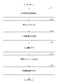
- FIG. 4 is a flowchart for explaining the operation of the charge/discharge management device
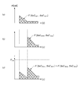
- FIG. 4 is a diagram showing an example of a charging power schedule for each time
- It is a figure which shows the hardware structural example of a charge/discharge management apparatus.
- SoC used in the following description is an abbreviation for State of charge, and is an index that indicates the remaining capacity of the storage battery. It is calculated by "remaining capacity / full charge capacity" of the storage battery, and is also called charging rate or state of charge.
- SoH is an abbreviation for State of health, which is called the degree of health, and represents the ratio of the full charge capacity at the time of deterioration when the initial full charge capacity of the storage battery is 100%.
- VRE is an abbreviation for Variable Renewable Energy, and refers to renewable energy that fluctuates in output, such as photovoltaic power generation.
- FIG. 1 shows an example of the overall configuration of a system according to an embodiment of the present invention. As shown in FIG. 1, this system includes a work scheduler 200, a charge/discharge management device 100, EV chargers 10-1 to 10-n, and EVs 20-1 to 20-n.
- the business scheduler 200 is an information system for individuals and organizations to input and share their own action plans, such as daily business schedules, meeting schedules, business trips and outing schedules.
- information is recorded that the EV user plans to go on a business trip or go out using the EV.
- the business scheduler 200 may be a system implemented by a physical computer network-connected to the charge/discharge management device 100, or may be a system on the cloud.
- the charge/discharge management device 100 creates a charge schedule and performs charge/discharge control for each EV. Details will be described later.
- the charge/discharge management device 100 may also be a system implemented by a physical computer or a system on the cloud.
- the EV charger 10 charges the EV 20.
- the EV charger 10 may include a discharge function, and the EV charger 10 having the discharge function may be called an EV charger/discharger.
- Each EV charger 10 is connected to the power distribution equipment (power receiving equipment) of the building and receives power supply from the power distribution equipment.
- a building's electrical distribution system is powered by, for example, a commercial power supply.
- each EV charger 10 may be supplied with power from a renewable energy source such as a solar power generator installed in a building.
- the EV 20 may be any vehicle as long as it is an electric vehicle, but in the present embodiment, it is assumed to be an electric vehicle.
- Fig. 1 shows an image of one EV charger corresponding to one EV, but this is an example.
- the number of EV chargers may be less than the number of EVs. Even in such a case, the charging schedule ensures that each EV is charged as closely as possible.
- FIG. 1 shows the case where the EV and the EV charger are separate, this is an example. You may use the vehicle-mounted charger mounted in EV.
- a vehicle-mounted charger includes, for example, an AC/DC converter, converts AC power into DC power, and charges a storage battery.
- the charge ON/OFF control and discharge control can be performed from the charge/discharge management device 100 in the same manner as in the case of the EV charger described below.
- FIG. 2 shows a functional configuration example of the charge/discharge management device 100.
- the charge/discharge management device 100 includes an information acquisition unit 110, a power consumption calculation unit 120, a charge schedule creation unit 130, a charge/discharge control unit 140, a notification unit 150, a correction unit 160, and a storage unit 170. .
- the information acquisition unit 110 acquires schedule information from the business scheduler 200 as information necessary for creating a charging schedule, and acquires information such as SoC related to the storage battery of each EV from each EV or each EV charger.
- the acquired information is stored in the storage unit 170 .
- the power consumption calculation unit 120 calculates the amount of power required to run the EV based on the schedule information of the EV user.
- the charging schedule creation unit 130 creates a charging schedule based on the amount of electric power of each EV calculated by the power consumption calculation unit 120.
- the charging/discharging control unit 140 performs charging or discharging by transmitting a control signal to the EV charger 10 based on the charging schedule.
- the notification unit 150 notifies the user.
- the correction unit 160 corrects schedule information, charging amount, and the like. Note that the correction by the correction unit 160 may not be performed.
- the information acquisition unit 110 extracts the EV usage time, destination, etc. from the business scheduler 200 that records the schedules of employees who use EVs, and calculates power consumption.
- a unit 120 calculates the amount of power required to move the EV.
- the charging schedule creation unit 130 calculates the amount of charge based on the amount of power required by each EV and the remaining capacity of the storage battery calculated by the power consumption calculation unit 120, and calculates the power used by the EV charger at each time. Then, a charging schedule is created so that all of the multiple EVs to be charged at the same time do not exceed a threshold (eg, the capacity of power receiving equipment).
- a threshold eg, the capacity of power receiving equipment
- the charging schedule creation unit 130 may create a charging schedule in cooperation with the power demand forecast for the building so that the demand for the entire building does not exceed the contracted power.
- the charging/discharging control unit 140 charges the EV 20 by transmitting a control signal to the corresponding EV charger 10 according to the created charging schedule.
- this embodiment targets charging multiple EVs, it is assumed that charging will not be done in time due to insufficient power receiving equipment or VRE capacity.
- the charging schedule creating unit 130 detects that a certain user will not be charged in time during the charging schedule creation, the charging schedule creating unit 130 reports this to the notification unit 150, and the notification unit 150 alerts the user. Send it and prompt you to change the schedule or charge at other charging stations.
- the notification unit 150 may make a phone call to the user's smartphone or the like, or may send a message.
- the notification unit 150 when detecting a schedule to a destination where public transportation can be used, prompts the user to travel by public transportation. You may send a message.
- the charge/discharge control unit 140 stores the storage unit 170 determines the amount of discharge based on the EV usage schedule and charging schedule stored in , and instructs the EV charger 10 (having a discharging function) of the EV 20 to discharge. As will be described later, discharging is performed by an EV whose storage battery has a sufficient remaining capacity (an EV with a remaining capacity that does not interfere with subsequent use).
- the schedule information obtained from the task scheduler 200 is not necessarily accurate, and the usage amount of mobility (that is, the amount of electric power used by EVs) differs depending on the user's characteristics (differences in driving style, etc.). In order to compensate for these uncertainties, the correction unit 160 corrects the schedule information.
- the correction unit 160 corrects the schedule information using each EV user's EV usage history (destination, travel distance, electricity cost), thereby increasing the accuracy of the amount of power required for mobility.
- some EV users perform actions other than business scheduler registration. Calculate the occurrence probability and the amount of movement of an action outside the schedule registered in the business scheduler.
- the correction unit 160 corrects, for example, based on the occurrence probability of an action outside the schedule and the amount of movement, the distance of the route when calculating the amount of power required to move the EV so as to be longer than the actual distance. . In other words, a distance margin is provided. Further, the correction unit 160 may correct the amount of power calculated by the power consumption calculation unit 120 based on the probability of occurrence of an action outside the schedule and the amount of movement. Further, the correction unit 160 determines a margin for the charge amount calculated by the charge schedule creation unit 130 based on the probability of occurrence of behavior outside the schedule and the amount of movement, notifies the charge schedule creation unit 130 of the margin, and performs charging. Schedule creation unit 130 may use the charge amount with the added margin for creating a charge schedule.
- correction unit 160 refers to the user's schedule information, and if it detects that a vacation or telecommuting application has already been made, lowers the charging priority of the user's EV. You may instruct
- the correction unit 160 lowers the priority of charging and issues an alert to the user from the notification unit 150. It may be sent.
- the information acquisition unit 110 of the charge/discharge management device 100 acquires the EV usage plan information (schedule information) of the EV user from the business trip information recorded in the work scheduler 200 .
- the usage schedule information to be acquired includes, for example, the destination of travel for a business trip, transit points to the destination, departure time, arrival time, type of EV, etc.
- the acquired usage schedule information is stored in the storage unit 170 . It should be noted that there may be cases in which there is no information on waypoints.
- the power consumption calculation unit 120 reads out the user's EV usage plan information from the storage unit 170, and calculates (predicts) the travel route of the EV based on the EV's current location, waypoints, and destination. Any method may be used to predict the travel route. For example, route calculation may be performed by acquiring map data from an external map information DB, or a route prediction service may be used by accessing an external route prediction application site. The information of the predicted route may include altitude information.
- the power consumption calculation unit 120 calculates the power amount P trav required for movement of the EV from the travel route of the EV and the electricity consumption data of the EV.
- Electricity consumption data for each vehicle type may be stored in the storage unit 170 in advance, or may be acquired from an external server or the like by designating the vehicle type of the EV.
- Electricity consumption is the distance traveled at 1 kWh or the amount of electricity consumed to travel 1 km. From the distance of the traveled route and the electricity consumption, it is possible to calculate the amount of electricity required to travel on that traveled route.
- the calculation of the electric energy by S1 to S3 is performed for each user (each EV) who is scheduled to go on a business trip on that day.
- the charging schedule creation unit 130 calculates, for each EV, the amount of power that is insufficient for the amount of power required for movement calculated in S3 from the remaining capacity of the storage battery of the EV, thereby charging the EV.
- a charging amount to be charged (target charging amount) is calculated.
- the charging schedule creation unit 130 calculates the charging amount of each EV using the following data (1) to (4) and formula (1).
- 1 and n in P bat1 , P batn , etc. are indices of EV.
- P bat1 to P batn Rated capacity of storage battery of each EV
- P EV1 to P EVn Remaining capacity of storage battery of each EV [kWh]
- P trav1 to P travn Amount of power [kWh] required for each EV for business trips
- P chg1 to P chgn Target charge amount [kWh] required for each EV
- the rated capacity of (1) may be stored in the storage unit 170 in advance, or may be acquired from an external server or the like.
- the remaining capacity in (2) may be obtained directly from the EV, or may be calculated from, for example, the rated capacity [kWh] of the storage battery and the SoC and SoH obtained from the EV.
- the amount of power in (3) is calculated in S3.
- Formula (1) is a formula for calculating the power amount that is insufficient with respect to the required power amount as the charge amount P chg for each EV. Note that P chg becomes a negative value when the remaining capacity is larger than the required power amount. As will be described later, this represents the amount of power that can be discharged.
- the charging schedule creation unit 130 creates a charging schedule based on the charge amount of each EV calculated in S4 so that the allowable power of the facility is not exceeded when charging a large number of EVs.
- F(SoC EVn , SoC EVn ') (t) is the current (before charge) EV battery remaining capacity SoC EVn for EVn (vehicle n) until it reaches the EV charge amount SoC EVn' after charge. It is a function representing the charging power [kW] at time t. Specifically, it represents the power [kW] used by each target charger.
- P chgn and F(SoC EVn , SoC EVn ′)(t) have a relationship represented by the following equation (2).
- Equation (2) indicates that the charge amount (P chgn ) is the integral of the charge power from the charge start time t1 to the charge end time t2.
- the function F(SoC EVn , SoC EVn ′)(t) is determined in advance for each vehicle type of EV and stored in the storage unit 170, for example.
- the charging schedule creation unit 150 can refer to F(SoC EVn , SoC EVn ′)(t) of any EV at any time. Also, the length of time from the start of charging t1 to the end of charging t2 may be determined so that equation (2) holds.
- Charging schedule creation unit 130 rearranges the columns P chg1 to P chgn of the charging amount of each EV obtained as a solution in equation (1) in descending order of departure time.
- the rearranged elements are P chg1′ to P chgn′ .
- the corresponding current (before charging) state of charge (remaining battery capacity) of each EV is defined as P EV1′ to P EVn′ .
- Charging schedule creation unit 130 creates a charging schedule so that each EV is charged to a charging amount of P chg so that the charging amount at each time does not exceed the power amount allowable for charging the EV.
- Multiple EVs can be charged at the same time as long as the amount of power that can be charged for EVs is not exceeded. At that time, batteries with earlier departure times may be preferentially charged according to the sorted order of departure times.
- the time is set so that the charging power value of all EVs that are charged at the same time is less than or equal to the threshold value P lim (e.g., the power receiving capacity of the building, or the value obtained by subtracting the power demand of the building from the power receiving capacity).
- P lim e.g., the power receiving capacity of the building, or the value obtained by subtracting the power demand of the building from the power receiving capacity.
- the charging schedule is created so that the total charging power of m units represented by the following equation (3) is less than or equal to the P lim value at each time t.
- FIG. 4(a) represents the charging power of EV1
- the area of the shaded portion represents the charging amount P chg1
- the graph in FIG. 4(b) represents the charging power of EV2
- the area of the shaded portion represents the charging amount P chg2 .
- the charging of EV1 is started earlier than the charging of EV2, thereby staggering the times when the charging power of EV1 and EV2 is high, and charging the two at the same time. Also, the charging schedule is such that the total charging power does not exceed P lim .
- Charging schedule creation unit 130 creates a charging schedule for each day, for example, based on the business trip schedule for that day, through the above-described process.
- the charging schedule is created so that the total charging power does not exceed P lim as described above, and the charging completion time of the EV is before the departure time of the EV.
- the charging schedule is represented, for example, by the charging start time and charging completion time for each EV.
- Charging schedule creation unit 130 stores the created charging schedule in storage unit 170 .
- the charging schedule creating unit 130 detects that an EV that cannot be fully charged before the departure time occurs while creating the charging schedule so as not to exceed P lim , the charging schedule creating unit 130 notifies it. Report to section 150 .
- the traffic unit 150 sends an alert to the user of the EV and recommends going to another charging station or using public transportation.
- the charging schedule creation unit 130 is designed to prevent an EV used by a specific user (executive, etc.) from being unable to complete charging before the departure time.
- a schedule for starting charging with the highest priority may be created.
- the charging/discharging control unit 140 reads out the charging schedule from the storage unit 170, and executes charging by transmitting a charging control signal to the EV charger 10 connected to the EV 20 according to the charging schedule.
- the charging schedule creation unit 130 or the charging/discharging control unit 140 reports to the notification unit 150, and the notification unit 150 notifies the user of the EV of the completion of charging.
- the charging schedule creation unit 130 can use EVs whose values are 0 or less (may be less than 0) among P chg1 to P chgn calculated by Equation (1) for purposes such as VPP (Virtual Power Plant). Then, information indicating that the EV can be used for VPP (information indicating that the EV can be used for discharging) is stored in storage unit 170 . Also, VPP utilization targets the amount that is a negative value of P chg .
- the charging/discharging control unit 140 instructs the EV charger 10 (having a discharging function) connected to the EV 20 capable of using the VPP to discharge, for example, based on an instruction from the electric power system of the building. For example, the electric energy of
- the discharged power may be used as power for a building, or may be supplied to an electric power company or the like through power distribution equipment.
- the charge/discharge management device 100 performs control to achieve compatibility between mobility use and VPP use.
- the charge/discharge management device 100 can be implemented, for example, by causing a computer to execute a program.
- This computer may be a physical computer or a virtual machine on the cloud.
- the charge/discharge management device 100 can be realized by executing a program corresponding to the processing performed by the charge/discharge management device 100 using hardware resources such as a CPU and memory built into the computer. is.
- the above program can be recorded in a computer-readable recording medium (portable memory, etc.), saved, or distributed. It is also possible to provide the above program through a network such as the Internet or e-mail.
- FIG. 5 is a diagram showing a hardware configuration example of the computer.
- the computer of FIG. 5 has a drive device 1000, an auxiliary storage device 1002, a memory device 1003, a CPU 1004, an interface device 1005, a display device 1006, an input device 1007, an output device 1008, etc., which are interconnected by a bus BS.
- a program that implements the processing in the computer is provided by a recording medium 1001 such as a CD-ROM or memory card, for example.
- a recording medium 1001 such as a CD-ROM or memory card
- the program is installed from the recording medium 1001 to the auxiliary storage device 1002 via the drive device 1000 .
- the program does not necessarily need to be installed from the recording medium 1001, and may be downloaded from another computer via the network.
- the auxiliary storage device 1002 stores installed programs, as well as necessary files and data.
- the memory device 1003 reads and stores the program from the auxiliary storage device 1002 when a program activation instruction is received.
- the CPU 1004 implements the functions of the light touch maintaining device 100 according to programs stored in the memory device 1003 .
- the interface device 1005 is used as an interface for connecting to the network.
- a display device 1006 displays a GUI (Graphical User Interface) or the like by a program.
- An input device 1007 is composed of a keyboard, a mouse, buttons, a touch panel, or the like, and is used to input various operational instructions.
- the output device 1008 outputs the calculation result.
- the technology according to the present embodiment enables charging with an appropriate charging amount without excessive charging exceeding the amount of mobility used by the EV.
- multiple EVs can be charged with the power required for business without excessively increasing the power equipment on the building side.
- This specification discloses at least a charge/discharge management device, a charge/discharge management method, and a program for each of the following items.
- (Section 1) an information acquisition unit that acquires schedule information regarding movement of a user of an electric vehicle; a power consumption calculation unit that calculates a travel distance of the electric vehicle based on the schedule information, and calculates a necessary amount of electric power required to move the electric vehicle from the travel distance; Based on the required power amount of each electric vehicle calculated by the power consumption calculation unit, a charging schedule for a plurality of electric vehicles is set so that the total charging power of the plurality of electric vehicles that are charged at the same time does not exceed a predetermined threshold.
- a charging/discharging management device comprising: a charging schedule creating unit to create; (Section 2) 2. The charging/discharging management device according to claim 1, wherein the charging schedule creation unit creates the charging schedule so that the charging of the electric vehicle is completed before the departure time of the electric vehicle. (Section 3) 3. The charge/discharge management device according to claim 1 or 2, further comprising a notification unit that transmits an alert to a user of an electric vehicle that cannot complete charging before departure time. (Section 4) 3. The charge/discharge management device according to any one of claims 1 to 3, comprising a correction unit that corrects the amount of charge for the electric vehicle of a certain user based on the usage history of the electric vehicle of the user. .
- the charging schedule creation unit determines an electric vehicle to be discharged as an electric vehicle having a negative charge amount calculated from the required electric energy and the remaining capacity of the storage battery.
- the charge/discharge management device according to any one of claims 1 to 3.
- (Section 6) A charge/discharge management method executed by a computer, an information acquisition step of acquiring schedule information regarding movement of the user of the electric vehicle; a power consumption calculation step of calculating a travel distance of the electric vehicle based on the schedule information, and calculating an amount of power required to move the electric vehicle from the travel distance; Based on the required power amount of each electric vehicle calculated in the power consumption calculation step, a charging schedule for the plurality of electric vehicles is determined so that the total charging power of the plurality of electric vehicles that are simultaneously charged does not exceed a predetermined threshold.
- a charging/discharging management method comprising: a charging schedule creating step; (Section 7) A program for causing a computer to function as each unit in the charge/discharge management device according to any one of items 1 to
Landscapes
- Engineering & Computer Science (AREA)
- Power Engineering (AREA)
- Transportation (AREA)
- Mechanical Engineering (AREA)
- Charge And Discharge Circuits For Batteries Or The Like (AREA)
Abstract
Description
前記スケジュール情報に基づいて、前記電動車両の移動距離を算出し、前記移動距離から前記電動車両の移動に要する必要電力量を算出する消費電力計算部と、
前記消費電力計算部により計算された各電動車両の必要電力量に基づいて、同時に充電を行う複数の電動車両の充電電力の合計が所定閾値を超えないように、複数の電動車両に対する充電スケジュールを作成する充電スケジュール作成部と
を備える充放電管理装置が提供される。
図1に本発明の実施の形態におけるシステムの全体構成例を示す。図1に示すように本システムは、業務スケジューラ200、充放電管理装置100、EV充電器10-1~10-n、EV20-1~20-nを備える。
図2に、充放電管理装置100の機能構成例を示す。図2に示すように、充放電管理装置100は、情報取得部110、消費電力計算部120、充電スケジュール作成部130、充放電制御部140、通知部150、補正部160、記憶部170を備える。
上記の構成を備える充放電管理装置100の基本的な動作例を説明する。
EVのモビリティ利用量を精度よく予測するために、情報取得部110が、EVを利用する社員等のスケジュールを記録した業務スケジューラ200から、EVの利用時刻、目的地等を抽出し、消費電力計算部120が、EVの移動に必要な電力量を算出する。
EVがビルに待機されている間に、V2X(ビルのピークカット(V2B)や系統安定化への利用(V2G))の利用を行う場合は、例えば、充放電制御部140が、記憶部170に格納されているEV利用スケジュール及び充電スケジュールに基づいて、放電量を決定し、該当EV20のEV充電器10(放電機能を有する)に放電を指示する。後述するように、放電に関しては、蓄電池の残容量が十分にあるEV(後の利用に支障をきたさない残容量があるEV)が行う。
業務スケジューラ200から得られるスケジュール情報は、必ずしも正確ではなく、利用者の特性(運転のしかたなどの相違)によってモビリティの利用量(つまりEVの使用電力量)が異なる。これらの不確実性を補償するために、補正部160がスケジュール情報の補正を行う。
以下、図3のフローチャートの手順に沿って、充放電管理装置100の詳細動作例を説明する。下記の動作の前提として、業務スケジューラ200には、例えば、EVの利用者毎のスケジュール情報(EV利用予定情報)が格納されているものとする。また、充放電管理装置100の記憶部170には、各利用者のEV利用履歴(走行ルート、ルート上の走行時刻等)が格納されているものとする。
S1において、充放電管理装置100の情報取得部110は、業務スケジューラ200に記録されている出張情報から、EV利用者のEVの利用予定情報(スケジュール情報)を取得する。
消費電力計算部120は、記憶部170から、利用者のEVの利用予定情報を読み出し、EVの現在地、経由地、目的地に基づいて、EVの走行ルートを算出(予測)する。走行ルートの予測はどのような方法を使用してもよい。例えば、外部にある地図情報DBから地図データを取得してルート計算をしてもよいし、外部のルート予測アプリケーションのサイトにアクセスしてルート予測サービスを利用してもよい。なお、予測するルートの情報には、高度の情報が含まれていてもよい。
S3において、消費電力計算部120は、EVの走行ルートと、当該EVの電費データとから当該EVが移動に要する電力量Ptravを算出する。車種毎の電費データについては、記憶部170に予め保持しておいてもよいし、EVの車種を指定することで外部サーバ等から取得してもよい。
S4において、充電スケジュール作成部130は、EV毎に、S3で算出した移動に必要な電力量に対して不足する電力量を、EVの蓄電池の残容量から算出することで、EVに対して充電すべき充電量(目標充電量)を算出する。具体的には、充電スケジュール作成部130は、各EVの充電量を、下記のデータ(1)~(4)を使用して、式(1)により算出する。以下のデータにおいて、Pbat1、Pbatnなどにおける1やnはEVのインデックスである。
(2)PEV1~PEVn:各EVの蓄電池残容量[kWh]
(3)Ptrav1~Ptravn:各EVが出張業務に必要な電力量[kWh]
(4)Pchg1~Pchgn:各EVに必要な目標充電量[kWh]

S5において、充電スケジュール作成部130は、S4で算出した各EVの充電量に基づいて、多数のEVへの充電を行う際に、設備側の許容電力を超えないように充電スケジュールを作成する。


S6において、充放電制御部140は、記憶部170から充電スケジュールを読み出し、充電スケジュールに従って、該当EV20に接続されたEV充電器10に充電制御信号を送信することで充電を実行する。
充電スケジュール作成部130は、式(1)で計算したPchg1~Pchgnのうち、値が0以下(0未満でもよい)になるEVについては、VPP(Virtual Power Plant)などの用途に利用可能と判断し、当該EVがVPPに利用可能であることを示す情報(放電に利用できることを示す情報)を記憶部170に記憶する。またVPP利用は、Pchgの負値となる量を対象とする。
充放電管理装置100は、例えば、コンピュータにプログラムを実行させることにより実現できる。このコンピュータは、物理的なコンピュータであってもよいし、クラウド上の仮想マシンであってもよい。
本実施の形態に係る技術により、EVのモビリティ利用量以上の過剰な充電を行うことなく、適切な充電量で充電が可能となる。また、ビル側の電力設備を過剰に増やすことなく、複数台のEVを業務に必要な分の電力を充電できる。
本明細書には、少なくとも下記各項の充放電管理装置、充放電管理方法、及びプログラムが開示されている。
(第1項)
電動車両の利用者の移動に関するスケジュール情報を取得する情報取得部と、
前記スケジュール情報に基づいて、前記電動車両の移動距離を算出し、前記移動距離から前記電動車両の移動に要する必要電力量を算出する消費電力計算部と、
前記消費電力計算部により計算された各電動車両の必要電力量に基づいて、同時に充電を行う複数の電動車両の充電電力の合計が所定閾値を超えないように、複数の電動車両に対する充電スケジュールを作成する充電スケジュール作成部と
を備える充放電管理装置。
(第2項)
前記充電スケジュール作成部は、電動車両の出発時刻の前に当該電動車両の充電が完了するように前記充電スケジュールを作成する
第1項に記載の充放電管理装置。
(第3項)
出発時刻の前に充電を完了させることができない電動車両の利用者へアラートを送信する通知部
を備える第1項又は第2項に記載の充放電管理装置。
(第4項)
ある利用者の電動車両の利用履歴に基づいて、当該利用者の電動車両に対する充電量の補正を行う補正部
を備える第1項ないし第3項のうちいずれか1項に記載の充放電管理装置。
(第5項)
前記充電スケジュール作成部は、前記必要電力量と蓄電池の残容量から算出される充電量が負の値となる電動車両を、放電を行わせる電動車両として決定する
第1項ないし第4項のうちいずれか1項に記載の充放電管理装置。
(第6項)
コンピュータが実行する充放電管理方法であって、
電動車両の利用者の移動に関するスケジュール情報を取得する情報取得ステップと、
前記スケジュール情報に基づいて、前記電動車両の移動距離を算出し、前記移動距離から前記電動車両の移動に要する必要電力量を算出する消費電力計算ステップと、
前記消費電力計算ステップにおいて計算された各電動車両の必要電力量に基づいて、同時に充電を行う複数の電動車両の充電電力の合計が所定閾値を超えないように、複数の電動車両に対する充電スケジュールを作成する充電スケジュール作成ステップと
を備える充放電管理方法。
(第7項)
コンピュータを、第1項ないし第5項のうちいずれか1項に記載の充放電管理装置における各部として機能させるためのプログラム。
20-1~20-n EV
100 充放電管理装置
110 情報取得部
120 消費電力計算部
130 充電スケジュール作成部
140 充放電制御部
150 通知部
160 補正部
170 記憶部
200 業務スケジューラ
1000 ドライブ装置
1001 記録媒体
1002 補助記憶装置
1003 メモリ装置
1004 CPU
1005 インタフェース装置
1006 表示装置
1007 入力装置
Claims (7)
- 電動車両の利用者の移動に関するスケジュール情報を取得する情報取得部と、
前記スケジュール情報に基づいて、前記電動車両の移動距離を算出し、前記移動距離から前記電動車両の移動に要する必要電力量を算出する消費電力計算部と、
前記消費電力計算部により計算された各電動車両の必要電力量に基づいて、同時に充電を行う複数の電動車両の充電電力の合計が所定閾値を超えないように、複数の電動車両に対する充電スケジュールを作成する充電スケジュール作成部と
を備える充放電管理装置。 - 前記充電スケジュール作成部は、電動車両の出発時刻の前に当該電動車両の充電が完了するように前記充電スケジュールを作成する
請求項1に記載の充放電管理装置。 - 出発時刻の前に充電を完了させることができない電動車両の利用者へアラートを送信する通知部
を備える請求項1又は2に記載の充放電管理装置。 - ある利用者の電動車両の利用履歴に基づいて、当該利用者の電動車両に対する充電量の補正を行う補正部
を備える請求項1ないし3のうちいずれか1項に記載の充放電管理装置。 - 前記充電スケジュール作成部は、前記必要電力量と蓄電池の残容量から算出される充電量が負の値となる電動車両を、放電を行わせる電動車両として決定する
請求項1ないし4のうちいずれか1項に記載の充放電管理装置。 - コンピュータが実行する充放電管理方法であって、
電動車両の利用者の移動に関するスケジュール情報を取得する情報取得ステップと、
前記スケジュール情報に基づいて、前記電動車両の移動距離を算出し、前記移動距離から前記電動車両の移動に要する必要電力量を算出する消費電力計算ステップと、
前記消費電力計算ステップにおいて計算された各電動車両の必要電力量に基づいて、同時に充電を行う複数の電動車両の充電電力の合計が所定閾値を超えないように、複数の電動車両に対する充電スケジュールを作成する充電スケジュール作成ステップと
を備える充放電管理方法。 - コンピュータを、請求項1ないし5のうちいずれか1項に記載の充放電管理装置における各部として機能させるためのプログラム。
Priority Applications (3)
| Application Number | Priority Date | Filing Date | Title |
|---|---|---|---|
| JP2023523936A JP7740332B2 (ja) | 2021-05-28 | 2021-05-28 | 充放電管理装置、充放電管理方法、及びプログラム |
| US18/562,296 US20250083551A1 (en) | 2021-05-28 | 2021-05-28 | Charge and discharge management apparatus, charge and discharge management method and program |
| PCT/JP2021/020538 WO2022249482A1 (ja) | 2021-05-28 | 2021-05-28 | 充放電管理装置、充放電管理方法、及びプログラム |
Applications Claiming Priority (1)
| Application Number | Priority Date | Filing Date | Title |
|---|---|---|---|
| PCT/JP2021/020538 WO2022249482A1 (ja) | 2021-05-28 | 2021-05-28 | 充放電管理装置、充放電管理方法、及びプログラム |
Publications (1)
| Publication Number | Publication Date |
|---|---|
| WO2022249482A1 true WO2022249482A1 (ja) | 2022-12-01 |
Family
ID=84229666
Family Applications (1)
| Application Number | Title | Priority Date | Filing Date |
|---|---|---|---|
| PCT/JP2021/020538 Ceased WO2022249482A1 (ja) | 2021-05-28 | 2021-05-28 | 充放電管理装置、充放電管理方法、及びプログラム |
Country Status (3)
| Country | Link |
|---|---|
| US (1) | US20250083551A1 (ja) |
| JP (1) | JP7740332B2 (ja) |
| WO (1) | WO2022249482A1 (ja) |
Families Citing this family (2)
| Publication number | Priority date | Publication date | Assignee | Title |
|---|---|---|---|---|
| JP7544084B2 (ja) * | 2022-02-09 | 2024-09-03 | トヨタ自動車株式会社 | 車両 |
| JP7605195B2 (ja) * | 2022-09-07 | 2024-12-24 | トヨタ自動車株式会社 | 充電支援システム |
Citations (5)
| Publication number | Priority date | Publication date | Assignee | Title |
|---|---|---|---|---|
| JP2013070575A (ja) * | 2011-09-26 | 2013-04-18 | Sony Corp | 蓄電制御装置、及び蓄電制御方法 |
| JP2014096928A (ja) * | 2012-11-09 | 2014-05-22 | Mitsubishi Heavy Ind Ltd | 充電スケジュール管理装置及び方法ならびにプログラム、それを備えた充電スケジュール管理システム |
| JP2015095983A (ja) * | 2013-11-13 | 2015-05-18 | パナソニックIpマネジメント株式会社 | 充放電管理システム |
| JP2015228716A (ja) * | 2014-05-30 | 2015-12-17 | 株式会社オートネットワーク技術研究所 | 電気自動車のバッテリー管理装置 |
| JP2021078248A (ja) * | 2019-11-08 | 2021-05-20 | パナソニックIpマネジメント株式会社 | 充電システム、充電方法、及びプログラム |
Family Cites Families (4)
| Publication number | Priority date | Publication date | Assignee | Title |
|---|---|---|---|---|
| JP5673084B2 (ja) * | 2010-12-27 | 2015-02-18 | マツダ株式会社 | 充電システム |
| JP2013002868A (ja) * | 2011-06-14 | 2013-01-07 | Navitime Japan Co Ltd | ナビゲーション装置、ナビゲーションシステム、ナビゲーションサーバ、ナビゲーション方法、および、プログラム |
| JP2015089266A (ja) * | 2013-10-31 | 2015-05-07 | 株式会社東芝 | 充電システム |
| JP2020108244A (ja) * | 2018-12-27 | 2020-07-09 | トヨタ自動車株式会社 | 車両およびその制御方法 |
-
2021
- 2021-05-28 WO PCT/JP2021/020538 patent/WO2022249482A1/ja not_active Ceased
- 2021-05-28 US US18/562,296 patent/US20250083551A1/en active Pending
- 2021-05-28 JP JP2023523936A patent/JP7740332B2/ja active Active
Patent Citations (5)
| Publication number | Priority date | Publication date | Assignee | Title |
|---|---|---|---|---|
| JP2013070575A (ja) * | 2011-09-26 | 2013-04-18 | Sony Corp | 蓄電制御装置、及び蓄電制御方法 |
| JP2014096928A (ja) * | 2012-11-09 | 2014-05-22 | Mitsubishi Heavy Ind Ltd | 充電スケジュール管理装置及び方法ならびにプログラム、それを備えた充電スケジュール管理システム |
| JP2015095983A (ja) * | 2013-11-13 | 2015-05-18 | パナソニックIpマネジメント株式会社 | 充放電管理システム |
| JP2015228716A (ja) * | 2014-05-30 | 2015-12-17 | 株式会社オートネットワーク技術研究所 | 電気自動車のバッテリー管理装置 |
| JP2021078248A (ja) * | 2019-11-08 | 2021-05-20 | パナソニックIpマネジメント株式会社 | 充電システム、充電方法、及びプログラム |
Also Published As
| Publication number | Publication date |
|---|---|
| JP7740332B2 (ja) | 2025-09-17 |
| US20250083551A1 (en) | 2025-03-13 |
| JPWO2022249482A1 (ja) | 2022-12-01 |
Similar Documents
| Publication | Publication Date | Title |
|---|---|---|
| US20230024900A1 (en) | System and method for real-time distributed micro-grid optimization using price signals | |
| US10320203B2 (en) | Adaptive charging algorithms for a network of electric vehicles | |
| KR101566715B1 (ko) | 충전 우선순위를 이용한 효율적인 전기자동차 충전 방법 및 시스템 | |
| EP3943336B1 (en) | Power reception control method for power storage element and power reception control device | |
| EP3611675A1 (en) | Method and device for determining a configuration for deployment of a public transportation system | |
| EP3944453A1 (en) | Power reception control method of power reception elements, and power reception control device | |
| US20130257372A1 (en) | Intelligent electric vehicle recharging | |
| JP6499939B2 (ja) | 二次電池の充電状態推定方法 | |
| Darabi et al. | An event-based simulation framework to examine the response of power grid to the charging demand of plug-in hybrid electric vehicles | |
| Naik et al. | Optimization of vehicle-to-grid (V2G) services for development of smart electric grid: A review | |
| TW201843906A (zh) | 蓄電池運用裝置及蓄電池運用方法 | |
| US20160086292A1 (en) | Price setting device and power regulation device | |
| CN116780595A (zh) | 电动汽车微电网能源管理方法、系统、设备及存储介质 | |
| JP2025146886A (ja) | 電池配送システム、及び電池配送方法 | |
| JP7740332B2 (ja) | 充放電管理装置、充放電管理方法、及びプログラム | |
| JP6616556B1 (ja) | 電力情報管理システム、管理方法、プログラム、電力情報管理サーバ、通信端末、及び、電力システム | |
| JP7715947B2 (ja) | 電気自動車拠点充電およびスケジューリングのためのネットワーク制約エネルギー管理システム | |
| CN113381406B (zh) | 一种电动汽车充放电控制方法、装置、设备及存储介质 | |
| Jithin Mohan et al. | Battery Management System-Based Fuzzy Logic | |
| Kwasinski et al. | Signal processing in the electrification of vehicular transportation: techniques for electric and plug-in hybrid electric vehicles on the smart grid | |
| Umoren et al. | EVaaS: A novel on-demand outage mitigation framework for electric vehicle enabled microgrids | |
| Koç et al. | Analysis the effects of electric vehicles on distribution networks with simulations based on probabilistic methods | |
| Yamaguchi et al. | Model predictive control of car storage battery in HEMS considered car traveling | |
| JP7643417B2 (ja) | サーバおよび車両管理方法 | |
| Szcześniak et al. | Optimal electric bus charging scheduling for local balancing of fluctuations in PV generation |
Legal Events
| Date | Code | Title | Description |
|---|---|---|---|
| 121 | Ep: the epo has been informed by wipo that ep was designated in this application |
Ref document number: 21943119 Country of ref document: EP Kind code of ref document: A1 |
|
| WWE | Wipo information: entry into national phase |
Ref document number: 2023523936 Country of ref document: JP |
|
| WWE | Wipo information: entry into national phase |
Ref document number: 18562296 Country of ref document: US |
|
| NENP | Non-entry into the national phase |
Ref country code: DE |
|
| 122 | Ep: pct application non-entry in european phase |
Ref document number: 21943119 Country of ref document: EP Kind code of ref document: A1 |
|
| WWP | Wipo information: published in national office |
Ref document number: 18562296 Country of ref document: US |