WO2022244853A1 - 蓄電デバイスの非透水性ガス抜きフィルム - Google Patents
蓄電デバイスの非透水性ガス抜きフィルム Download PDFInfo
- Publication number
- WO2022244853A1 WO2022244853A1 PCT/JP2022/020888 JP2022020888W WO2022244853A1 WO 2022244853 A1 WO2022244853 A1 WO 2022244853A1 JP 2022020888 W JP2022020888 W JP 2022020888W WO 2022244853 A1 WO2022244853 A1 WO 2022244853A1
- Authority
- WO
- WIPO (PCT)
- Prior art keywords
- water
- film
- layer
- exterior material
- storage device
- Prior art date
- Legal status (The legal status is an assumption and is not a legal conclusion. Google has not performed a legal analysis and makes no representation as to the accuracy of the status listed.)
- Ceased
Links
Images








Classifications
-
- H—ELECTRICITY
- H01—ELECTRIC ELEMENTS
- H01M—PROCESSES OR MEANS, e.g. BATTERIES, FOR THE DIRECT CONVERSION OF CHEMICAL ENERGY INTO ELECTRICAL ENERGY
- H01M50/00—Constructional details or processes of manufacture of the non-active parts of electrochemical cells other than fuel cells, e.g. hybrid cells
- H01M50/30—Arrangements for facilitating escape of gases
- H01M50/317—Re-sealable arrangements
-
- H—ELECTRICITY
- H01—ELECTRIC ELEMENTS
- H01M—PROCESSES OR MEANS, e.g. BATTERIES, FOR THE DIRECT CONVERSION OF CHEMICAL ENERGY INTO ELECTRICAL ENERGY
- H01M50/00—Constructional details or processes of manufacture of the non-active parts of electrochemical cells other than fuel cells, e.g. hybrid cells
- H01M50/30—Arrangements for facilitating escape of gases
- H01M50/394—Gas-pervious parts or elements
-
- B—PERFORMING OPERATIONS; TRANSPORTING
- B32—LAYERED PRODUCTS
- B32B—LAYERED PRODUCTS, i.e. PRODUCTS BUILT-UP OF STRATA OF FLAT OR NON-FLAT, e.g. CELLULAR OR HONEYCOMB, FORM
- B32B7/00—Layered products characterised by the relation between layers; Layered products characterised by the relative orientation of features between layers, or by the relative values of a measurable parameter between layers, i.e. products comprising layers having different physical, chemical or physicochemical properties; Layered products characterised by the interconnection of layers
- B32B7/04—Interconnection of layers
- B32B7/12—Interconnection of layers using interposed adhesives or interposed materials with bonding properties
-
- C—CHEMISTRY; METALLURGY
- C09—DYES; PAINTS; POLISHES; NATURAL RESINS; ADHESIVES; COMPOSITIONS NOT OTHERWISE PROVIDED FOR; APPLICATIONS OF MATERIALS NOT OTHERWISE PROVIDED FOR
- C09J—ADHESIVES; NON-MECHANICAL ASPECTS OF ADHESIVE PROCESSES IN GENERAL; ADHESIVE PROCESSES NOT PROVIDED FOR ELSEWHERE; USE OF MATERIALS AS ADHESIVES
- C09J7/00—Adhesives in the form of films or foils
- C09J7/20—Adhesives in the form of films or foils characterised by their carriers
- C09J7/22—Plastics; Metallised plastics
- C09J7/24—Plastics; Metallised plastics based on macromolecular compounds obtained by reactions involving only carbon-to-carbon unsaturated bonds
- C09J7/241—Polyolefin, e.g.rubber
-
- H—ELECTRICITY
- H01—ELECTRIC ELEMENTS
- H01G—CAPACITORS; CAPACITORS, RECTIFIERS, DETECTORS, SWITCHING DEVICES, LIGHT-SENSITIVE OR TEMPERATURE-SENSITIVE DEVICES OF THE ELECTROLYTIC TYPE
- H01G11/00—Hybrid capacitors, i.e. capacitors having different positive and negative electrodes; Electric double-layer [EDL] capacitors; Processes for the manufacture thereof or of parts thereof
- H01G11/14—Arrangements or processes for adjusting or protecting hybrid or EDL capacitors
- H01G11/20—Reformation or processes for removal of impurities, e.g. scavenging
-
- H—ELECTRICITY
- H01—ELECTRIC ELEMENTS
- H01G—CAPACITORS; CAPACITORS, RECTIFIERS, DETECTORS, SWITCHING DEVICES, LIGHT-SENSITIVE OR TEMPERATURE-SENSITIVE DEVICES OF THE ELECTROLYTIC TYPE
- H01G11/00—Hybrid capacitors, i.e. capacitors having different positive and negative electrodes; Electric double-layer [EDL] capacitors; Processes for the manufacture thereof or of parts thereof
- H01G11/78—Cases; Housings; Encapsulations; Mountings
-
- H—ELECTRICITY
- H01—ELECTRIC ELEMENTS
- H01G—CAPACITORS; CAPACITORS, RECTIFIERS, DETECTORS, SWITCHING DEVICES, LIGHT-SENSITIVE OR TEMPERATURE-SENSITIVE DEVICES OF THE ELECTROLYTIC TYPE
- H01G9/00—Electrolytic capacitors, rectifiers, detectors, switching devices, light-sensitive or temperature-sensitive devices; Processes of their manufacture
- H01G9/004—Details
- H01G9/08—Housing; Encapsulation
- H01G9/12—Vents or other means allowing expansion
-
- H—ELECTRICITY
- H01—ELECTRIC ELEMENTS
- H01M—PROCESSES OR MEANS, e.g. BATTERIES, FOR THE DIRECT CONVERSION OF CHEMICAL ENERGY INTO ELECTRICAL ENERGY
- H01M50/00—Constructional details or processes of manufacture of the non-active parts of electrochemical cells other than fuel cells, e.g. hybrid cells
- H01M50/10—Primary casings; Jackets or wrappings
- H01M50/102—Primary casings; Jackets or wrappings characterised by their shape or physical structure
- H01M50/103—Primary casings; Jackets or wrappings characterised by their shape or physical structure prismatic or rectangular
-
- H—ELECTRICITY
- H01—ELECTRIC ELEMENTS
- H01M—PROCESSES OR MEANS, e.g. BATTERIES, FOR THE DIRECT CONVERSION OF CHEMICAL ENERGY INTO ELECTRICAL ENERGY
- H01M50/00—Constructional details or processes of manufacture of the non-active parts of electrochemical cells other than fuel cells, e.g. hybrid cells
- H01M50/10—Primary casings; Jackets or wrappings
- H01M50/102—Primary casings; Jackets or wrappings characterised by their shape or physical structure
- H01M50/105—Pouches or flexible bags
-
- H—ELECTRICITY
- H01—ELECTRIC ELEMENTS
- H01M—PROCESSES OR MEANS, e.g. BATTERIES, FOR THE DIRECT CONVERSION OF CHEMICAL ENERGY INTO ELECTRICAL ENERGY
- H01M50/00—Constructional details or processes of manufacture of the non-active parts of electrochemical cells other than fuel cells, e.g. hybrid cells
- H01M50/10—Primary casings; Jackets or wrappings
- H01M50/102—Primary casings; Jackets or wrappings characterised by their shape or physical structure
- H01M50/107—Primary casings; Jackets or wrappings characterised by their shape or physical structure having curved cross-section, e.g. round or elliptic
-
- H—ELECTRICITY
- H01—ELECTRIC ELEMENTS
- H01M—PROCESSES OR MEANS, e.g. BATTERIES, FOR THE DIRECT CONVERSION OF CHEMICAL ENERGY INTO ELECTRICAL ENERGY
- H01M50/00—Constructional details or processes of manufacture of the non-active parts of electrochemical cells other than fuel cells, e.g. hybrid cells
- H01M50/10—Primary casings; Jackets or wrappings
- H01M50/116—Primary casings; Jackets or wrappings characterised by the material
- H01M50/117—Inorganic material
- H01M50/119—Metals
-
- H—ELECTRICITY
- H01—ELECTRIC ELEMENTS
- H01M—PROCESSES OR MEANS, e.g. BATTERIES, FOR THE DIRECT CONVERSION OF CHEMICAL ENERGY INTO ELECTRICAL ENERGY
- H01M50/00—Constructional details or processes of manufacture of the non-active parts of electrochemical cells other than fuel cells, e.g. hybrid cells
- H01M50/10—Primary casings; Jackets or wrappings
- H01M50/116—Primary casings; Jackets or wrappings characterised by the material
- H01M50/121—Organic material
-
- H—ELECTRICITY
- H01—ELECTRIC ELEMENTS
- H01M—PROCESSES OR MEANS, e.g. BATTERIES, FOR THE DIRECT CONVERSION OF CHEMICAL ENERGY INTO ELECTRICAL ENERGY
- H01M50/00—Constructional details or processes of manufacture of the non-active parts of electrochemical cells other than fuel cells, e.g. hybrid cells
- H01M50/10—Primary casings; Jackets or wrappings
- H01M50/116—Primary casings; Jackets or wrappings characterised by the material
- H01M50/124—Primary casings; Jackets or wrappings characterised by the material having a layered structure
- H01M50/126—Primary casings; Jackets or wrappings characterised by the material having a layered structure comprising three or more layers
- H01M50/129—Primary casings; Jackets or wrappings characterised by the material having a layered structure comprising three or more layers with two or more layers of only organic material
-
- H—ELECTRICITY
- H01—ELECTRIC ELEMENTS
- H01M—PROCESSES OR MEANS, e.g. BATTERIES, FOR THE DIRECT CONVERSION OF CHEMICAL ENERGY INTO ELECTRICAL ENERGY
- H01M50/00—Constructional details or processes of manufacture of the non-active parts of electrochemical cells other than fuel cells, e.g. hybrid cells
- H01M50/10—Primary casings; Jackets or wrappings
- H01M50/183—Sealing members
- H01M50/184—Sealing members characterised by their shape or structure
-
- H—ELECTRICITY
- H01—ELECTRIC ELEMENTS
- H01M—PROCESSES OR MEANS, e.g. BATTERIES, FOR THE DIRECT CONVERSION OF CHEMICAL ENERGY INTO ELECTRICAL ENERGY
- H01M50/00—Constructional details or processes of manufacture of the non-active parts of electrochemical cells other than fuel cells, e.g. hybrid cells
- H01M50/30—Arrangements for facilitating escape of gases
- H01M50/342—Non-re-sealable arrangements
- H01M50/3425—Non-re-sealable arrangements in the form of rupturable membranes or weakened parts, e.g. pierced with the aid of a sharp member
-
- B—PERFORMING OPERATIONS; TRANSPORTING
- B32—LAYERED PRODUCTS
- B32B—LAYERED PRODUCTS, i.e. PRODUCTS BUILT-UP OF STRATA OF FLAT OR NON-FLAT, e.g. CELLULAR OR HONEYCOMB, FORM
- B32B27/00—Layered products comprising a layer of synthetic resin
- B32B27/32—Layered products comprising a layer of synthetic resin comprising polyolefins
-
- C—CHEMISTRY; METALLURGY
- C09—DYES; PAINTS; POLISHES; NATURAL RESINS; ADHESIVES; COMPOSITIONS NOT OTHERWISE PROVIDED FOR; APPLICATIONS OF MATERIALS NOT OTHERWISE PROVIDED FOR
- C09J—ADHESIVES; NON-MECHANICAL ASPECTS OF ADHESIVE PROCESSES IN GENERAL; ADHESIVE PROCESSES NOT PROVIDED FOR ELSEWHERE; USE OF MATERIALS AS ADHESIVES
- C09J2203/00—Applications of adhesives in processes or use of adhesives in the form of films or foils
- C09J2203/326—Applications of adhesives in processes or use of adhesives in the form of films or foils for bonding electronic components such as wafers, chips or semiconductors
-
- H—ELECTRICITY
- H01—ELECTRIC ELEMENTS
- H01G—CAPACITORS; CAPACITORS, RECTIFIERS, DETECTORS, SWITCHING DEVICES, LIGHT-SENSITIVE OR TEMPERATURE-SENSITIVE DEVICES OF THE ELECTROLYTIC TYPE
- H01G11/00—Hybrid capacitors, i.e. capacitors having different positive and negative electrodes; Electric double-layer [EDL] capacitors; Processes for the manufacture thereof or of parts thereof
- H01G11/14—Arrangements or processes for adjusting or protecting hybrid or EDL capacitors
- H01G11/18—Arrangements or processes for adjusting or protecting hybrid or EDL capacitors against thermal overloads, e.g. heating, cooling or ventilating
-
- Y—GENERAL TAGGING OF NEW TECHNOLOGICAL DEVELOPMENTS; GENERAL TAGGING OF CROSS-SECTIONAL TECHNOLOGIES SPANNING OVER SEVERAL SECTIONS OF THE IPC; TECHNICAL SUBJECTS COVERED BY FORMER USPC CROSS-REFERENCE ART COLLECTIONS [XRACs] AND DIGESTS
- Y02—TECHNOLOGIES OR APPLICATIONS FOR MITIGATION OR ADAPTATION AGAINST CLIMATE CHANGE
- Y02E—REDUCTION OF GREENHOUSE GAS [GHG] EMISSIONS, RELATED TO ENERGY GENERATION, TRANSMISSION OR DISTRIBUTION
- Y02E60/00—Enabling technologies; Technologies with a potential or indirect contribution to GHG emissions mitigation
- Y02E60/10—Energy storage using batteries
Definitions
- the present disclosure relates to a water impermeable gas release film for an electricity storage device.
- metal exterior materials are often used as exterior materials.
- Patent Document 1 discloses a battery in which a battery element is housed in a pouch.
- the pouch is fitted with a valve structure having a check valve in a heat seal formed along its periphery. This check valve is configured to operate and degas when the internal pressure of the pouch rises above a certain level.
- Patent Document 2 discloses a battery in which a battery element is housed in a box-shaped laminate container.
- This laminated container has a flange-shaped heat-sealed portion formed along the periphery thereof, which is formed with a portion (hereinafter referred to as an easy peel portion) that is easier to peel than other portions.
- the easy peel portion is peeled off when the internal pressure of the laminated container rises above a certain level, and gas is released through a hole formed in the center of the easy peel portion.
- the easy peel portion is a break valve that does not return to its original state once it is peeled off, unlike the check valve disclosed in Patent Document 1.
- the main purpose of the present disclosure is to provide a water-impermeable gas release film for an electricity storage device, which can be easily attached to the exterior material of the electricity storage device and can discharge gas generated inside the electricity storage device.
- the non-water-permeable gas release film is adhered to the surface of the exterior material so as to close the communication part provided in the exterior material of the electricity storage device, and the gas generated inside the energy storage device is discharged from the communication part.
- the water impermeable gas venting film is composed of a laminate including at least a base layer and an adhesive layer, and the adhesive layer of the water impermeable gas venting film is adhered to the surface of the electricity storage device. It was found that by using the impermeable gas release film, it is easy to attach to the exterior material of the electricity storage device, and the gas generated inside the electricity storage device can be discharged.
- the inventor of the present disclosure arranges a non-water-permeable gas release film between the welded parts of the exterior material of the electricity storage device so that the gas generated inside the electricity storage device is discharged.
- the water-impermeable gas venting film is composed of a laminate including at least a base material layer and an adhesive layer, and the adhesive layer of the water-impermeable gas venting film is adhered to the welded portion of the exterior material, and the water-impermeable By allowing the gas to permeate in the thickness direction of the gas venting film and discharging the gas generated inside the electricity storage device, it is easy to attach the electricity storage device to the exterior material, and the gas generated inside the electricity storage device. It was also found that the gas can be discharged.
- the present disclosure provides the invention of the first aspect and the invention of the second aspect listed below.
- the invention of the first aspect of the present disclosure adheres to the surface of the exterior material so as to block the communication portion provided in the exterior material of the electricity storage device, and the gas generated inside the electricity storage device is transferred to the communication portion.
- the adhesive layer of the water permeable gas venting film is a non-water permeable gas venting film adhered to the surface of the electrical storage device.
- the invention of the second aspect of the present disclosure is arranged to be interposed between the welded portions of the exterior material of the electricity storage device, and used to discharge gas generated inside the electricity storage device,
- An impermeable gas venting film wherein the water impermeable gas venting film is composed of a laminate comprising at least a substrate layer and an adhesive layer, and the adhesive layer of the water impermeable gas venting film is a water impermeable gas venting film adhered to the welded portion of the exterior material, the gas permeating in the thickness direction of the water impermeable gas venting film, and the gas being discharged.
- a water-impermeable gas venting film for an electricity storage device which can be easily attached to the exterior material of the electricity storage device and can discharge gas generated inside the electricity storage device.
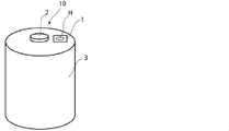
- FIG. 2 is a schematic diagram of an example in which the water-impermeable gas venting film of the first aspect of the present disclosure is applied to the surface of the exterior material (square metal can) of an electricity storage device.
- FIG. 2 is a schematic diagram of an example in which the water-impermeable gas venting film of the first aspect of the present disclosure is applied to the surface of the exterior material (square metal can) of an electricity storage device.
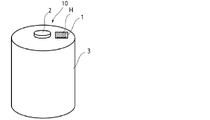
- 1 is a schematic diagram of an example in which the water-impermeable gas venting film of the first aspect of the present disclosure is applied to the surface of the exterior material (cylindrical metal can) of an electricity storage device.
- FIG. 1 is a schematic diagram of an example in which the water-impermeable gas venting film of the first aspect of the present disclosure is applied to the surface of the exterior material (cylindrical metal can) of an electricity storage device.
- FIG. 1 is a schematic diagram of an example in which the water-impermeable gas venting film of the first aspect of the present disclosure is applied to the surface of the exterior material (cylindrical metal can) of an electricity storage device.
- FIG. 2 is a schematic diagram of an example in which the water-impermeable gas venting film of the first aspect of the present disclosure is applied to the surface of the exterior material (laminated film) of the electrical storage device.
- FIG. 2 is a schematic diagram of an example in which the water-impermeable gas venting film of the first aspect of the present disclosure is applied to the surface of the exterior material (laminated film) of the electrical storage device.
- FIG. 1 is a schematic diagram of an example in which the water-impermeable gas venting film of the first aspect of the present disclosure is applied to the surface of the exterior material (cylindrical metal can) of an electricity storage device.
- FIG. 2 is a schematic diagram of an example in which the water-impermeable gas venting film of the first aspect
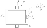
- FIG. 4 is a schematic diagram of an example in which the water-impermeable gas venting film of the first aspect of the present disclosure is applied to the welded portion of the exterior material (laminated film) of the electrical storage device.
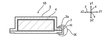
- FIG. 8 is a schematic cross-sectional view taken along line A-A' in FIG. 7;
- FIG. 9 is an enlarged view of the area IX in FIG. 8;
- FIG. 4 is a schematic diagram of an example in which the non-water-permeable gas venting film of the second aspect of the present disclosure is applied to the welded portion of the exterior material (laminated film) of the electrical storage device.
- FIG. 11 is a schematic cross-sectional view taken along line A-A' in FIG. 10;
- FIG. 12 is an enlarged view of area XII of FIG.
- FIG. 2 is a schematic cross-sectional view of a water impermeable gas venting film in which two water impermeable gas venting films are stacked and only the ends are heat-sealed to form a folded shape.
- FIG. 4 is a schematic diagram of an example in which the non-water-permeable gas venting film of the second aspect of the present disclosure is applied to the welded portion of the exterior material (laminated film) of the electrical storage device.
- FIG. 15 is a schematic cross-sectional view taken along line A-A' of FIG. 14;
- FIG. 16 is an enlarged view of the area XVI of FIG. 15;
- FIG. 4 is a schematic diagram of an example in which the non-water-permeable gas venting film of the second aspect of the present disclosure is applied to the welded portion of the exterior material (laminated film) of the electrical storage device.
- FIG. 18 is a schematic cross-sectional view taken along line A-A' in FIG. 17;
- FIG. 19 is an enlarged view of the area XIX of FIG. 18;
- 1 is an example schematic cross-sectional view of a water impermeable venting film of the present disclosure;
- FIG. 1 is an example schematic cross-sectional view of a water impermeable venting film of the present disclosure;
- FIG. 1 is an example schematic cross-sectional view of a water impermeable venting film of the present disclosure;
- FIG. 1 is an example schematic cross-sectional view of a water impermeable venting film of the present disclosure;
- FIG. 1 is a schematic cross-sectional view of an exterior material made of a laminated film;
- the water-impermeable gas venting film of the first aspect of the present disclosure is adhered to the surface of the exterior material so as to block the communicating portion provided in the exterior material of the electrical storage device, and the gas generated inside the electrical storage device is released.
- a non-permeable gas venting film used for discharging from the communicating part which is composed of a laminate comprising at least a base material layer and an adhesive layer, and bonding the non-permeable gas venting film The layer is characterized in that it is adhered to the surface of the electrical storage device.
- the water-impermeable gas venting film of the first aspect can be easily attached to the exterior material of the electricity storage device and can discharge the gas generated inside the electricity storage device.
- the water-impermeable gas release film of the second aspect of the present disclosure is arranged so as to be interposed between the welded portions of the exterior material of the electricity storage device, and is used to discharge the gas generated inside the electricity storage device.
- the water impermeable gas venting film used is composed of a laminate comprising at least a base layer and an adhesive layer, and the adhesive layer of the water impermeable gas venting film is attached to the exterior material. It is characterized in that the gas permeates in the thickness direction of the non-water-permeable gas venting film, and the gas is discharged.
- the non-water-permeable gas venting film of the second aspect can be easily attached to the exterior material of the electricity storage device and can discharge the gas generated inside the electricity storage device.
- the numerical range indicated by “-” means “more than” and “less than”.
- the notation of 2 to 15 mm means 2 mm or more and 15 mm or less.
- the non-water-permeable gas vent films of the first aspect and the second aspect of the present disclosure are adhesive films used in electrical storage devices, respectively.
- First, in the first aspect and the second aspect, how to use the non-water-permeable gas venting film of the present disclosure in an electricity storage device will be described in detail, and then the laminated structure of the water-impermeable gas-venting film Also, the characteristics and physical properties of the resin used for each layer will be described in detail.
- the water-impermeable gas venting film of the first aspect of the present disclosure is adhered to the surface of the exterior material so as to close the communication portion provided in the exterior material of the electricity storage device, and the gas generated inside the electricity storage device is used to discharge from the communication part.
- the adhesive layer is adhered to the surface of the electricity storage device, so that the water-impermeable gas venting film connects the communicating portion provided in the exterior material of the electricity storage device. It is adhered to the surface of the exterior material so as to block it.
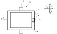
- the water-impermeable gas release film 1 of the first embodiment blocks the communication portion H provided in the exterior material 3 of the electricity storage device 10, and the exterior material 3 is adhered to the surface.
- the gas generated inside the electricity storage device 10 (the electricity storage device element 4 ) permeates the water-impermeable gas venting film 1 and is discharged from the communication portion H.
- the communication portion H is a communication portion that connects the electricity storage device element 4 to the outside, and the non-water-permeable degassing film 1 suppresses the infiltration of moisture from the outside of the electricity storage device 10.
- the gas generated in the device element 4) is discharged to the outside.
- FIG. 1 and 2 illustrate a mode in which the exterior material 3 of the electricity storage device 10 is made of a rectangular metal can.
- 3 and 4 illustrate a mode in which the exterior material 3 of the electricity storage device 10 is configured by a cylindrical metal can.
- the surface of the exterior material 3 to which the impermeable gas release film 1 is adhered is made of metal. That is, in the first aspect, when the water impermeable gas venting film 1 is applied to the exterior material 3 made of a metal can, the adhesive layer 12 of the water impermeable gas venting film 1 is impermeable and gas permeable. and is adhesive to the metal forming the outer surface of the exterior material 3 .
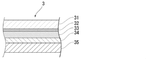
- the exterior material 3 of the electricity storage device 10 is composed of a laminate (laminated film) including at least a base layer 31, a barrier layer 33, and a heat-fusible resin layer 35 in this order.
- Fig. 3 illustrates an embodiment
- the surface of the exterior material 3 to which the impermeable gas release film 1 is adhered is made of resin. That is, in the first aspect, when the impermeable gas venting film 1 is applied to the exterior material 3 composed of a laminated film, the adhesive layer 12 of the impermeable gas venting film 1 is impermeable to water and gas permeable. and is adhesive to the resin forming the outer surface of the exterior material.
- the shape (shape in plan view) of the communicating portion H provided in the exterior material 3 is not particularly limited.
- FIGS. 2, 4, and 6 show configurations in which the communication portion H is slit-shaped.
- the position where the communication portion H is provided is not particularly limited, and it can be provided on the bottom surface, side surface, or welded portion of the electricity storage device 10 .
- FIGS. 1 to 6 show modes in which the communicating portion H is provided on the bottom surface (which can also be referred to as an upper surface, a lower surface, a top surface, etc.) of the electricity storage device 10.
- FIG. 7 to 9 the communication portion H is a welded portion of the electricity storage device 10 (a welded portion between the heat-sealable resin layers 35 formed on the peripheral edge portion 3a of the exterior material 3, which will be described later). 1 illustrates an embodiment provided in the . As shown in FIGS.
- the gas generated inside the electricity storage device 10 reaches the non-water-permeable gas venting film 1 through the communicating portion H, and the gas permeates in the thickness direction of the non-water-permeable gas venting film 1.
- the impermeable gas venting film 1 is adhered to the surface of the electricity storage device 10 .
- gas can permeate the water impermeable gas venting film 1 because the distance through which the gas permeates is short.
- the distance through which the gas permeates becomes longer, so the gas hardly permeates.
- the non-water-permeable gas release film 1 is adhered to the surface of the exterior material 3 so as to block the communication portion H provided in the exterior material 3 of the electricity storage device 10, thereby making the non-water-permeable It is important to permeate the gas in the thickness direction of the gas venting film 1 .
- the communicating portion H shown in FIGS. 7 to 9 is a welded portion of the electric storage device 10 (a welded portion of the heat-sealable resin layer 35 formed on the peripheral edge portion 3a of the exterior material 3, which will be described later).
- the non-water-permeable gas venting film 1 is attached to the communication portion H provided in a part of the welded portion of the peripheral edge 3a of the exterior material 3, and the enlarged view of FIG.
- the gas generated inside the electric storage device 10 permeates in the thickness direction of the non-water-permeable gas venting film 1 and is discharged to the outside.
- the heat-sealable resin layer 35 of the exterior material 3 described later and the adhesive layer 12 of the water-impermeable gas venting film 1 are bonded at the welded portion of the water-impermeable gas venting film 1.
- the non-water-permeable gas venting film 1 is interposed in the welded portion, and a part of the welded portion is provided with a portion where the heat-sealable resin layers 35 are not welded to each other, and this portion can be used as the communicating portion H. . It is also possible to partially form a portion where the heat-sealable resin layer 35 is not provided on the exterior material 3 and use this portion as the communication portion H.
- the non-water-permeable gas venting film of the second aspect of the present disclosure is arranged so as to be interposed between the welded portions of the exterior material of the electricity storage device, in order to discharge the gas generated inside the electricity storage device.
- the adhesive layer of the water impermeable gas venting film is adhered to the welded portion of the exterior material, and gas permeates in the thickness direction of the water impermeable gas venting film. As a result, the gas generated inside the power storage device is discharged to the outside.
- the opening of the communicating portion of the exterior material is formed in the water impermeable gas venting film.
- the non-water-permeable gas release film is arranged so as to be interposed between the welded portions of the exterior material so as to block the thickness direction.
- the gas generated inside the electricity storage device 10 permeates the water-impermeable gas release film 1 and is discharged. That is, the non-permeable gas venting film 1 disposed between the welded parts plays a role of blocking the communication part connecting the electricity storage device element 4 to the outside. Intrusion of water is suppressed, and gas generated inside the electricity storage device 10 (the electricity storage device element 4) is discharged to the outside.
- the non-permeable gas venting film 1 arranged between the welded parts into a folded shape in addition to the method of folding the non-permeable gas venting film 1, for example, as shown in the schematic diagram of FIG. As shown, two impermeable gas venting films may be superimposed and heat-sealed only at the ends (position of the heat-sealed portion HS in FIG. 13) to form a folded shape.
- the heat-sealing of the two impermeable gas venting films 1 may be performed before the impermeable gas venting film 1 is arranged between the welded parts, or the welded part of the exterior material 3 may be
- two non-permeable gas venting films are placed in an overlapping state between the exterior materials 3, and the edges of the non-water permeable gas venting film 1 are heat-sealed together with the formation of the welded portion.
- the impermeable gas venting film 1 is arranged at the welded part of the exterior material 3 so that a part of the impermeable gas venting film 1 protrudes from the welded part of the exterior material 3, and the non-permeable gas venting film 1 is It is desirable to design such that the gas permeates in the thickness direction of the water-permeable gas venting film and the gas is discharged.
- the exterior material 3 of the electricity storage device 10 is composed of a laminate (laminated film) comprising at least a base layer 31, a barrier layer 33, and a heat-fusible resin layer 35 in this order.
- Fig. 3 illustrates the embodiment in which the laminate (laminated film)
- the welding portion formed on the peripheral edge portion 3a of the exterior material 3 is made of resin (for example, a heat-sealable resin layer 35 of the exterior material 3 described later). It is that is, in the second aspect, when the impermeable gas venting film 1 is applied to the exterior material 3 composed of a laminated film, the impermeable gas venting film 1 is made of a resin having water impermeability and gas permeability. It can be made of a resin having adhesiveness to the resin constituting the innermost layer of the exterior material (that is, the heat-fusible resin layer 35 of the exterior material 3 described later).
- the impermeable gas venting film 1 is partially protruded from the welded portion of the exterior material 3 so that the impermeable gas venting film 1 is attached to the exterior material. It can also be arranged at the welding part of 3.
- the portion of the non-permeable gas venting film 1 protruding from the welded portion is heat-sealed at the peripheral edge and has a bag shape, and as shown in the schematic diagram of FIG. It is arranged so that gas permeates from the thickness direction of the gas release film 1 .
- two non-permeable gas venting films 1 are laminated, and three sides of the portion where the non-permeable gas venting film 1 protrudes from the welded portion (x1 side in FIG. 14, x2 side , z1 side) are heat-sealed, but one water-impermeable degassing film 1 is folded back to form two sides (x1 side in FIG. 14, x2 side) ) is heat-sealed (the z1 side is a folded portion).
- the welded portion of the exterior material 3 may be provided with a communication portion H where the surface of the impermeable gas release film 1 is exposed. Gas can also be discharged through the communicating portion H.
- the shape of the communication portion H (the shape in plan view) is not particularly limited. For example, in FIG. It may be a shape or the like.
- the gas can permeate the impermeable gas venting film 1 because the gas permeation distance in the thickness direction of the impermeable gas venting film 1 is short.
- the distance through which the gas permeates becomes longer, so the gas hardly permeates. Therefore, in the second aspect as well, it is important to permeate the gas in the thickness direction of the impermeable gas venting film 1 .
- the non-water-permeable gas venting film 1 of the present disclosure is composed of a laminate including at least a substrate layer 11 and an adhesive layer 12 . Furthermore, the non-water-permeable gas venting film 1 of the present disclosure has a function of allowing gas generated inside the electrical storage device to permeate in the thickness direction of the non-water-permeable gas venting film 1 . In addition, the water-impermeable gas venting film 1 is water-impermeable.
- the water impermeable gas venting film 1 of the present disclosure as a whole is permeable to the gas generated inside the electricity storage device (gas can be permeated in the thickness direction of the water impermeable gas venting film 1), and the electricity storage device It must have water impermeability that can suppress the infiltration of moisture from the external environment.
- the water-impermeable gas venting film 1 of the present disclosure preferably has a water vapor permeability of 10 cc/m when left standing in an environment of 60° C. and 90% RH for 48 hours. 2 /day or less, more preferably 5 cc/m 2 /day or less, still more preferably 2 cc/m 2 /day or less, and still more preferably 0 cc/m 2 /day.
- a method for measuring the water vapor transmission rate of the water impermeable gas venting film 1 is as follows.
- Water vapor permeability is measured in an environment of 60° C. and 90% RH in accordance with the cup method of JIS Z 0208.
- a sample of 75 mm ⁇ is cut out as a test piece by a screw tightening method, and three holes of 5 mm ⁇ are drilled 5 mm inward from the outer periphery and set on a jig.
- a cup with a transmission area of 60 mm ⁇ is used.
- the water-impermeable gas venting film 1 of the present disclosure preferably has a carbon dioxide permeability of 5000 cm 3 /(m 2 ⁇ 24 h ⁇ atm) or more, more preferably It is 8000 cm 3 /(m 2 ⁇ 24 h ⁇ atm) or more, more preferably 10000 cm 3 /(m 2 ⁇ 24 h ⁇ atm) or more.
- the upper limit of the carbon dioxide permeability of the water impermeable gas venting film 1 of the present disclosure is, for example, 100000 cm 3 /(m 2 ⁇ 24 h ⁇ atm) or less.
- a method for measuring the carbon dioxide permeability of the water impermeable gas venting film 1 is as follows.
- the water impermeable gas venting film 1 of the present disclosure preferably has an oxygen permeability of 50 cm 3 /(m 2 ⁇ 24 h ⁇ atm) or more, more preferably 100 cm 3 /(m 2 ⁇ 24 h ⁇ atm) or more, more preferably 200 cm 3 /(m 2 ⁇ 24 h ⁇ atm) or more.
- the upper limit of the oxygen permeability of the water impermeable gas venting film 1 of the present disclosure is, for example, 100000 cm 3 /(m 2 ⁇ 24 h ⁇ atm) or less.
- a method for measuring the oxygen permeability of the water-impermeable gas venting film 1 is as follows.
- Oxygen permeability is measured according to JIS K7126-2: 2006 (Plastics - Film and sheet - Gas permeability test method - Part 2: Isobaric method, Appendix A: Oxygen gas permeability test method by electrolytic sensor method). It can be measured using an oxygen gas permeation measurement device under the conditions of a temperature of 40° C. and a humidity of 90% RH. For example, OXTRAN2/22 manufactured by MOCON, USA can be used as the oxygen gas permeability measuring device.
- the measurement is carried out under the condition that the surface of the water-impermeable degassing film is placed in the above-described apparatus so that the surface thereof is in contact with oxygen gas, and the permeation area is 50 cm 2 .
- the above measurements are performed according to the following procedure. First, the inside of the apparatus is purged by supplying a carrier gas at a flow rate of 10 cc/min for 60 minutes or more. Nitrogen gas containing about 5% hydrogen can be used as the carrier gas. After purging, the test gas is allowed to flow through the apparatus, and after 12 hours have been secured from the start of the flow until reaching the equilibrium state, the measurement is started under the above temperature and humidity conditions.
- the test gas used is dry oxygen containing at least 99.5% (by volume) oxygen. At least three samples are measured for each condition, and the average of these measurements is taken as the oxygen permeability value for that condition.
- a polyolefin resin is a resin that has a low water vapor permeability and a high carbon dioxide permeability, and is suitable as a resin that constitutes the water impermeable gas venting film 1 of the present disclosure.
- polyesters, polyamides, polyurethanes, polycarbonates, polyvinyl alcohols, and the like have high water vapor permeability and are not suitable as resins constituting the water impermeable gas venting film 1 of the present disclosure.
- polyester, polyamide, vinyl fluoride resin, AS resin (acrylonitrile styrene copolymer), polyacetal, etc. have low carbon dioxide gas permeability and are not suitable as resins constituting the water impermeable gas venting film 1 of the present disclosure. It can be said.
- the water impermeable gas venting film 1 of the present disclosure has a structure in which at least a substrate layer 11 and an adhesive layer 12 are laminated, and the adhesive layer 12 is provided on one side of the water impermeable gas venting film 1. make up the surface.
- the non-water-permeable gas venting film 1 may further include at least one resin layer on the substrate layer 11 side of the adhesive layer 12 .
- the resin layer is laminated between the adhesive layer 12 and the substrate layer 11 on the side of the substrate layer 11 opposite to the adhesive layer 12 side.
- the resin layer is at least one layer.
- FIG. 1 illustrates a stacking arrangement comprising: Laminated configurations of the water impermeable gas venting film 1 of the present disclosure include a two-layer configuration, a three-layer configuration, a four-layer configuration, a five-layer configuration, and the like. Among these, a two-layer structure or a three-layer structure is preferable.
- a laminated structure of the water-impermeable gas venting film 1 of the present disclosure for example, a two-layer structure in which a base layer 11 and an adhesive layer 12 are laminated in this order (see FIG. 20); and resin layer 13 are laminated in this order (see FIG. 21); See ).
- the total thickness of the water impermeable gas venting film 1 of the present disclosure is, for example, about 5 ⁇ m or more, preferably about 20 ⁇ m or more, and more preferably about 30 ⁇ m or more, from the viewpoint of suitably exhibiting the effects of the present disclosure.
- the total thickness of the water impermeable gas venting film 1 of the present disclosure is, for example, about 500 ⁇ m or less, preferably about 200 ⁇ m or less, more preferably 180 ⁇ m or less.
- Preferred ranges for the total thickness of the water impermeable gas venting film 1 of the present disclosure are about 5 to 500 ⁇ m, about 5 to 200 ⁇ m, about 5 to 180 ⁇ m, about 20 to 500 ⁇ m, about 20 to 200 ⁇ m, about 20 to 180 ⁇ m, 30 up to about 500 ⁇ m, about 30 to 200 ⁇ m, and about 30 to 180 ⁇ m.
- the total thickness is preferably about 60 to 100 ⁇ m. When used, the total thickness is preferably about 80 to 500 ⁇ m.
- the material and thickness of the substrate layer 11, the adhesive layer 12, and the resin layer provided as necessary for example, the resin layer 13, the resin layer 14, etc. included in the water-impermeable gas venting film 1 of the present disclosure and so on.
- the substrate layer 11 is a layer that functions as a support.
- the base material layer 11 is preferably made of a resin having a low water vapor permeability and a high carbon dioxide permeability.
- the base material layer 11 is preferably a layer containing a polyolefin resin (that is, having a polyolefin skeleton), and more preferably a layer formed of a polyolefin resin.
- polyolefin resins include polyolefins such as polyethylene and polypropylene.
- the polyolefin-based resin may be a resin (acid-modified polyolefin) in which polyolefin is acid-modified.
- the acid-modified polyolefin is not particularly limited as long as it is an acid-modified polyolefin, but preferably includes a polyolefin graft-modified with an unsaturated carboxylic acid or its anhydride, such as acid-modified polyethylene and acid-modified polypropylene. .
- Polyolefins include polyethylenes such as low density polyethylene, medium density polyethylene, high density polyethylene and linear low density polyethylene, respectively; homopolypropylene, block copolymers of polypropylene (e.g. block copolymers of propylene and ethylene), random copolymers of polypropylene ( Examples include crystalline or amorphous polypropylene such as random copolymer of propylene and ethylene; terpolymer of ethylene-butene-propylene. Among these polyolefins, polyethylene and polypropylene are preferred.
- the polyolefin may be a cyclic polyolefin.
- Cyclic polyolefins are copolymers of olefins and cyclic monomers.
- olefins that are constituent monomers of cyclic polyolefins include ethylene, propylene, 4-methyl-1-pentene, butadiene, and isoprene.
- cyclic monomers constituting the cyclic polyolefin include cyclic alkenes such as norbornene; specific examples thereof include cyclic dienes such as cyclopentadiene, dicyclopentadiene, cyclohexadiene and norbornadiene.
- cyclic alkenes are preferred, and norbornene is more preferred.
- Constituent monomers also include styrene.
- the above-mentioned polyolefin is also preferable for the acid-modified polyolefin.
- the carboxylic acid-modified cyclic polyolefin is obtained by copolymerizing a part of the monomers constituting the cyclic polyolefin with ⁇ , ⁇ -unsaturated carboxylic acid or its anhydride, or by copolymerizing the cyclic polyolefin. It is a polymer obtained by block polymerization or graft polymerization of ⁇ , ⁇ -unsaturated carboxylic acid or its anhydride.
- Carboxylic acids or anhydrides thereof used for acid modification include, for example, maleic acid, acrylic acid, itaconic acid, crotonic acid, maleic anhydride, and itaconic anhydride.
- the polyolefin resin is analyzed by infrared spectroscopy, it is preferable that a peak derived from maleic anhydride is detected.
- peaks derived from maleic anhydride are detected near wavenumbers of 1760 cm ⁇ 1 and 1780 cm ⁇ 1 .
- the polyolefin resin when measured by infrared spectroscopy, a peak derived from maleic anhydride is detected.
- the peak may be too small to be detected. In that case, it can be analyzed by nuclear magnetic resonance spectroscopy.
- the base material layer 11 may be formed of one resin component alone, or may be formed of a blend polymer in which two or more resin components are combined. From the viewpoint of the film formability of the base material layer 11, it is preferable to form the base material layer 11 with a blend polymer in which two or more resin components are combined.
- the base material layer 11 is mainly composed of acid-modified polypropylene (50% by mass or more), and 50% by mass or less is another resin (preferably polyethylene from the viewpoint of improving flexibility). It is preferable to On the other hand, from the viewpoint of enhancing the electrolyte resistance of the base layer 11, the base layer 11 preferably contains polypropylene or acid-modified polypropylene alone as a resin.
- the base material Layer 11 preferably has excellent heat resistance.
- the melting peak temperature of the resin constituting the substrate layer 11 is preferably 100°C or higher, more preferably 120°C or higher, and even more preferably 140°C or higher.
- about the upper limit of the melting peak temperature of resin which comprises the base material layer 11, 300 degrees C or less is mentioned, for example.
- the method for measuring the melting peak temperature of the resin is as follows.
- the melting peak temperature is measured in accordance with JIS K7121:2012 (Method for measuring transition temperature of plastics (JIS K7121:1987 Supplement 1)). The measurement is performed using a differential scanning calorimeter (for example, DSC, Differential Scanning Calorimeter Q200 manufactured by TA Instruments). After holding the measurement sample at ⁇ 50° C. for 15 minutes, the temperature was raised from ⁇ 50° C. to 210° C. at a heating rate of 10° C./min, and the first melting peak temperature P (° C.) was measured. Hold at 210° C. for 10 minutes. Next, the temperature is lowered from 210° C. to ⁇ 50° C.
- DSC Differential Scanning Calorimeter Q200 manufactured by TA Instruments
- the temperature is raised from ⁇ 50° C. to 210° C. at a heating rate of 10° C./min, and the second melting peak temperature Q (° C.) is measured.
- the flow rate of nitrogen gas is 50 ml/min.
- the thickness of the base layer 11 is preferably about 10 ⁇ m or more, more preferably about 20 ⁇ m or more, still more preferably about 30 ⁇ m or more, and preferably about 300 ⁇ m or less, more preferably about 200 ⁇ m or less, more preferably about 150 ⁇ m or less. about 150 ⁇ m, about 30-300 ⁇ m, about 30-200 ⁇ m, and about 30-150 ⁇ m.
- the ratio of the thickness of the base material layer 11 to the total thickness (100%) of the water-impermeable gas venting film 1 is preferably about 5% or more. , More preferably about 10% or more, still more preferably about 15% or more, preferably about 95% or less, more preferably about 90% or less, still more preferably about 85% or less. , about 5 to 95%, about 5 to 90%, about 5 to 85%, about 10 to 95%, about 10 to 90%, about 10 to 85%, about 15 to 95%, about 15 to 90%, 15 ⁇ 85%.
- the adhesive layer 12 is a layer having adhesiveness to the exterior material 3 of the electricity storage device 10 . Specifically, in the first aspect, it has adhesiveness to the surface of the exterior material 3, and in the second aspect, it has adhesiveness (preferably heat-sealing) to the welded portion of the exterior material 3. there is
- the layer 12 can be made of a resin that is water-impermeable and gas-permeable, and is adhesive (preferably heat-sealable) to the metal forming the outer surface of the exterior material 3 .
- the impermeable gas venting film 1 when applying the impermeable gas venting film 1 to the outer surface of the exterior material 3 composed of the laminated film, the impermeable gas venting film
- the first adhesive layer 12 can be made of a resin that is impermeable to water and gas-permeable, and that has adhesiveness (preferably heat-sealability) to the resin forming the outer surface of the exterior material. .
- the non-water-permeable gas venting film 1 is a resin having water impermeability and gas permeability, and is the innermost layer of the exterior material. (that is, a heat-fusible resin layer 35 of the exterior material 3 to be described later).
- the adhesive layer 12 is preferably made of a resin having a low water vapor permeability and a high carbon dioxide permeability.
- the adhesive layer 12 is preferably a layer containing a polyolefin resin (that is, having a polyolefin skeleton), more preferably a layer formed of a polyolefin resin.
- polyolefin resins include polyolefins such as polyethylene and polypropylene.
- the polyolefin-based resin may be a resin obtained by acid-modifying polyolefin (acid-modified polyolefin).
- the acid-modified polyolefin is not particularly limited as long as it is an acid-modified polyolefin, but preferably includes a polyolefin graft-modified with an unsaturated carboxylic acid or its anhydride, such as acid-modified polyethylene and acid-modified polypropylene. .
- polyolefin-based resin in the adhesive layer 12 are the same as the polyolefin and acid-modified polyolefin exemplified in the base material layer 11, so the above examples are used.
- the adhesive layer 12 may be formed from one type of resin component alone, or may be formed from a blend polymer in which two or more types of resin components are combined. From the viewpoint of the film formability of the adhesive layer 12, it is preferable to form the adhesive layer 12 with a blend polymer in which two or more resin components are combined.
- the adhesive layer 12 is mainly composed of acid-modified polypropylene (50% by mass or more), and 50% by mass or less is another resin (preferably polyethylene from the viewpoint of improving flexibility). preferably.
- the adhesive layer 12 preferably contains polypropylene or acid-modified polypropylene alone as the resin.
- the adhesive layer 12 may contain an adhesive component.
- An elastomer etc. are mentioned as an adhesive component.
- the elastomer is not particularly limited as long as it is compounded with polyolefin and exhibits adhesiveness.
- an elastomer (thermoplastic elastomer) made of a thermoplastic resin is preferable.
- elastomers include styrene-based elastomers, olefin-based elastomers, acrylic-based elastomers, silicone-based elastomers, urethane-based elastomers, polyester-based elastomers, polyamide-based elastomers, and rubber-based elastomers.
- One type of elastomer may be used alone, or two or more types may be used in combination.
- styrene-based elastomer is not particularly limited, but specific examples include styrene-butadiene-styrene block copolymer, styrene-isoprene-styrene block copolymer, styrene-ethylene-butylene-styrene block copolymer, and styrene-ethylene-propylene. - Styrene block copolymers and the like.
- olefinic elastomers examples include copolymers of ⁇ -olefins having 2 to 20 carbon atoms such as ethylene, propylene, 1-butene, 1-hexene, 4-methyl-pentene. ), ethylene-propylene-diene copolymer (EPDM), and the like. Copolymers of non-conjugated dienes having 2 to 20 carbon atoms such as dicyclopentadiene, 1,4-hexadiene, cyclooctadiene, methylenenorbornene, ethylidenenorbornene, butadiene and isoprene with ⁇ -olefins are also included. Further examples include carboxy-modified nitrile rubber obtained by copolymerizing butadiene-acrylonitrile copolymer with methacrylic acid.
- the acrylic elastomer is mainly composed of acrylic acid ester, and specifically, ethyl acrylate, butyl acrylate, methoxyethyl acrylate, ethoxyethyl acrylate, etc. are preferably used. Moreover, glycidyl methacrylate, allyl glycidyl ether, etc. are used as a cross-linking monomer. Furthermore, acrylonitrile and ethylene can also be copolymerized.
- acrylonitrile-butyl acrylate copolymer examples include acrylonitrile-butyl acrylate copolymer, acrylonitrile-butyl acrylate-ethyl acrylate copolymer, acrylonitrile-butyl acrylate-glycidyl methacrylate copolymer and the like.
- the silicone-based elastomer is mainly composed of organopolysiloxane, and includes polydimethylsiloxane-based, polymethylphenylsiloxane-based, and polydiphenylsiloxane-based elastomers.
- Urethane-based elastomers are composed of structural units of hard segments composed of low-molecular-weight ethylene glycol and diisocyanate, and soft segments composed of high-molecular-weight (long-chain) diols and diisocyanate.
- a polyester-based elastomer is obtained by polycondensing a dicarboxylic acid or its derivative and a diol compound or its derivative.
- dicarboxylic acids include aromatic dicarboxylic acids such as terephthalic acid, isophthalic acid and naphthalenedicarboxylic acid, and aromatic dicarboxylic acids in which the hydrogen atoms of these aromatic nuclei are substituted with methyl groups, ethyl groups, phenyl groups, etc.
- Aliphatic dicarboxylic acids having 2 to 20 carbon atoms such as adipic acid, sebacic acid and dodecanedicarboxylic acid, and alicyclic dicarboxylic acids such as cyclohexanedicarboxylic acid and the like are included. These compounds can be used individually by 1 type or in mixture of 2 or more types.
- diol compounds include aliphatic diols such as ethylene glycol, 1,3-propanediol, 1,4-butanediol, 1,6-hexanediol, 1,10-decanediol, and 1,4-cyclohexanediol. and alicyclic diols, and further bisphenol A, bis-(4-hydroxyphenyl)-methane, bis-(4-hydroxy-3-methylphenyl)-propane, resorcinol, and the like. These compounds can be used individually by 1 type or in mixture of 2 or more types.
- Polyamide-based elastomers include polyamide as a hard segment component, polybutadiene, butadiene-acrylonitrile copolymer, styrene-butadiene copolymer, polyisoprene, ethylene-propylene copolymer, polyether, polyester, polybutadiene, polycarbonate, polyacrylate, Examples thereof include block copolymers having soft segment components such as polymethacrylate, polyurethane or silicone rubber.
- Examples of rubber-based elastomers include polyisobutylene.
- styrene-based elastomers and olefin-based elastomers are preferred, and styrene-based elastomers are particularly preferred.
- the proportion of the elastomer contained in the adhesive layer 12 is not particularly limited, but is preferably about 50% by mass or less, more preferably about 10-50% by mass, and even more preferably about 10-40% by mass.
- the melting peak temperature of the resin constituting the adhesive layer 12 is preferably 300° C. or lower, more preferably 200° C. or lower, and still more preferably 160° C. or lower. It is preferably 100° C. or higher, more preferably 120° C. or higher, and still more preferably 140° C. or higher. , about 120 to 200°C, about 120 to 160°C, about 140 to 300°C, about 140 to 200°C, and about 140 to 160°C.
- the thickness of the adhesive layer 12 is preferably about 10 ⁇ m or more, more preferably about 20 ⁇ m or more, still more preferably about 30 ⁇ m or more, and preferably about 300 ⁇ m.
- the thickness of the adhesive layer 12 is preferably about 10 ⁇ m or more, more preferably about 20 ⁇ m or more, still more preferably about 30 ⁇ m or more, and preferably about 300 ⁇ m.
- more preferably about 200 ⁇ m or less more preferably about 150 ⁇ m or less. They are about 150 ⁇ m, about 30 to 300 ⁇ m, about 30 to 200 ⁇ m, and about 30 to 150 ⁇ m.
- the ratio of the thickness of the adhesive layer 12 to the total thickness (100%) of the water-impermeable gas venting film 1 is preferably about 5% or more, More preferably about 10% or more, still more preferably about 15% or more, preferably about 95% or less, more preferably about 90% or less, still more preferably about 85% or less.
- the water-impermeable gas venting film 1 of the present disclosure has a multilayer structure, and in addition to the substrate layer 11 and the adhesive layer 12, at least one resin layer is further added to the substrate layer 11 side of the adhesive layer 12. be prepared.
- the resin layer is laminated between the adhesive layer 12 and the substrate layer 11 on the side of the substrate layer 11 opposite to the adhesive layer 12 side.
- the resin layer is at least one layer.
- FIG. 1 illustrates a stacking arrangement comprising:
- the resin layer is preferably made of a resin having a low water vapor permeability and a high carbon dioxide permeability.
- the resin layer is preferably a layer containing a polyolefin resin (that is, having a polyolefin skeleton), and more preferably a layer formed of a polyolefin resin.
- polyolefin resins include polyolefins such as polyethylene and polypropylene.
- the polyolefin-based resin may be a resin obtained by acid-modifying polyolefin (acid-modified polyolefin).
- the acid-modified polyolefin is not particularly limited as long as it is an acid-modified polyolefin, but preferably includes a polyolefin graft-modified with an unsaturated carboxylic acid or its anhydride, such as acid-modified polyethylene and acid-modified polypropylene. .
- the resin layer specific examples of the polyolefin-based resin are the same as the polyolefin and acid-modified polyolefin exemplified for the base material layer 11, so the above examples are used.
- the resin layer may contain an adhesive component as in the case of the adhesive layer 12 .
- the adhesive component include elastomers, and specific examples thereof are the same as those of the adhesive layer 12, so the description is incorporated.
- the melting peak temperature of the resin constituting the resin layer is preferably 350° C. or lower, more preferably 300° C. or lower, still more preferably 250° C. or lower, and is preferably 100° C. or higher, more preferably 120° C. or higher. It is preferably 140° C. or higher.
- the thickness of each resin layer is preferably about 10 ⁇ m or more, more preferably about 20 ⁇ m, from the viewpoint of more preferably exhibiting the effects of the present disclosure. More preferably, it is about 30 ⁇ m or more, and preferably about 500 ⁇ m or less, more preferably about 300 ⁇ m or less, and even more preferably about 200 ⁇ m or less.
- the water impermeable gas venting film 1 of the present disclosure includes a resin layer, from the viewpoint of more suitably exhibiting the effects of the present disclosure, with respect to the total thickness (100%) of the water impermeable gas venting film 1,
- the thickness ratio of each resin layer is preferably about 5% or more, more preferably about 10% or more, still more preferably about 15% or more, and preferably about 95% or less, more preferably about 90%. Below, it is more preferably about 85% or less. %, about 15 to 95%, about 15 to 90%, and about 15 to 85%.
- the water-impermeable gas venting film 1 should be substantially free of polyester, polyamide, polyurethane, polycarbonate, polyvinyl alcohol, vinyl fluoride resin, AS resin, or polyacetal. is also preferred. Substantially free of these resins means that the total proportion of these resins in the water-impermeable gas venting film 1 is 5% by mass or less, further 1% by mass or less, and further 0% by mass.
- the resin constituting the water-impermeable gas venting film 1 preferably has a polyolefin resin content of preferably 90% by mass or more, more preferably 95% by mass or more, and even more preferably 95% by mass or more. is 98% by mass or more, more preferably 100% by mass.
- At least one layer may contain additives such as coloring agents such as pigments, fillers, and lubricants in addition to resins. good.
- Examples of the exterior material 3 of the electricity storage device 10 include a metal can and a laminated film.
- FIGS. 1 and 2 illustrate a mode in which the exterior material 3 of the electric storage device 10 is configured by a rectangular metal can.
- 3 and 4 illustrate a mode in which the exterior material 3 of the electricity storage device 10 is configured by a cylindrical metal can. 5 to 12 and FIGS. 14 to 19, the exterior material 3 of the electricity storage device 10 includes a laminated film (for example, at least a base layer 31, a barrier layer 33, and a heat-fusible resin layer 35 in this order). 2 shows an embodiment constructed from a laminate).
- At least terminals 2 are provided on the outer surface of the electricity storage device 10 in addition to the exterior material 3 .
- the terminal 2 is a member for electrically connecting the inside and the outside of the electricity storage device 10 and extracting electricity from the electricity storage device 10 .
- the exterior material is a metal can
- the exterior material is made of metal, and examples of metal include stainless steel, aluminum alloy, and steel plate.
- the exterior material 3 made of a laminated film may have a laminated structure consisting of a laminated body having at least a base layer 31, a barrier layer 33, and a heat-fusible resin layer 35 in this order.
- FIG. 23 shows, as an example of the cross-sectional structure of the exterior material 3, a substrate layer 31, an adhesive layer 32 provided as necessary, a barrier layer 33, an adhesive layer 34 provided as necessary, and a heat-sealable resin. A mode in which the layers 35 are laminated in this order is shown.
- the base material layer 31 is the outer layer
- the heat-sealable resin layer 35 is the innermost layer.
- FIGS. 5 to 12 and FIGS. 14 to 19 show the power storage device 10 using the embossed exterior material 3 formed by embossing or the like, but the exterior material 3 is not molded. It may be a pouch type that is not attached.
- the pouch type includes a three-sided seal, a four-sided seal, a pillow type, and the like, and any type may be used.
- the thickness of the laminate constituting the exterior material 3 is not particularly limited, but the upper limit is, for example, 190 ⁇ m or less, preferably about 180 ⁇ m or less, about 160 ⁇ m or less, about 155 ⁇ m from the viewpoint of cost reduction, energy density improvement, etc.
- the upper limit is, for example, 190 ⁇ m or less, preferably about 180 ⁇ m or less, about 160 ⁇ m or less, about 155 ⁇ m from the viewpoint of cost reduction, energy density improvement, etc.
- about 140 ⁇ m or less, about 130 ⁇ m or less, about 120 ⁇ m or less can be mentioned, and the lower limit is preferably about 35 ⁇ m or more and about 45 ⁇ m or more from the viewpoint of maintaining the function of the exterior material 3 to protect the electricity storage device element 4 .
- about 60 ⁇ m or more, and about 80 ⁇ m or more is preferably about 60 ⁇ m or more, and about 80 ⁇ m or more.
- the water-impermeable gas venting film 1 of the present disclosure can be suitably applied to the exterior material for all-solid-state batteries, and the thickness of the laminate constituting the exterior material for all-solid-state batteries is particularly limited.
- it is preferably about 10000 ⁇ m or less, about 8000 ⁇ m or less, about 5000 ⁇ m or less, and from the viewpoint of maintaining the function of the all-solid battery exterior material to protect the battery element. is preferably about 100 ⁇ m or more, about 150 ⁇ m or more, about 200 ⁇ m or more. about 150 to 5000 ⁇ m, about 200 to 10000 ⁇ m, about 200 to 8000 ⁇ m, and about 200 to 5000 ⁇ m, and particularly preferably about 100 to 5000 ⁇ m.
- the base material layer 31 is a layer that functions as a base material of the exterior material, and is a layer that forms the outermost layer side.
- the material forming the base layer 31 is not particularly limited as long as it has insulating properties.
- Materials for forming the base material layer 31 include, for example, polyester, polyamide, epoxy, acrylic, fluororesin, polyurethane, silicon resin, phenol, polyetherimide, polyimide, and mixtures and copolymers thereof.
- Polyester such as polyethylene terephthalate and polybutylene terephthalate, has the advantage of being excellent in electrolyte resistance and less likely to cause whitening or the like due to adhesion of the electrolyte.
- the polyamide film is excellent in stretchability, and can prevent occurrence of whitening due to cracking of the resin in the base layer 31 during molding.
- the base material layer 31 may be formed of a uniaxially or biaxially stretched resin film, or may be formed of an unstretched resin film. Among them, a uniaxially or biaxially stretched resin film, particularly a biaxially stretched resin film, is preferably used as the substrate layer 31 because its heat resistance is improved by oriented crystallization.
- the resin film forming the base layer 31 is preferably nylon or polyester, more preferably biaxially oriented nylon or biaxially oriented polyester.
- the all-solid-state battery has a temperature resistance of 150° C. or higher, it is often sealed at a high temperature of 200° C. or higher, and biaxially stretched polyester is most suitable.
- the base material layer 31 can also be laminated with resin films made of different materials in order to improve the pinhole resistance and the insulating properties when the electric storage device is packaged.
- resin films made of different materials in order to improve the pinhole resistance and the insulating properties when the electric storage device is packaged.
- Specific examples include a multilayer structure in which a polyester film and a nylon film are laminated, a multilayer structure in which a biaxially stretched polyester and a biaxially stretched nylon are laminated, and the like.
- each resin film may be adhered via an adhesive, or may be directly laminated without an adhesive.
- a method of bonding in a heat-melted state such as a coextrusion method, a sand lamination method, a thermal lamination method, or the like can be used.
- At least the outermost layer is desirably made of biaxially oriented polyester for high temperature sealing.
- the base material layer 31 may be made to have low friction in order to improve moldability.
- the coefficient of friction of the surface thereof is not particularly limited, but may be, for example, 1.0 or less.
- matte treatment, formation of a thin film layer of a slip agent, combination thereof, and the like can be mentioned.
- the thickness of the base material layer 31 is, for example, about 10-50 ⁇ m, preferably about 15-30 ⁇ m.
- the adhesive layer 32 is a layer arranged on the base material layer 31 as necessary in order to impart adhesiveness to the base material layer 31 . That is, the adhesive layer 32 is provided between the base material layer 31 and the barrier layer 33 .
- the adhesive layer 32 is made of an adhesive that can bond the base layer 31 and the barrier layer 33 together.
- the adhesive used to form the adhesive layer 32 may be a two-component curing adhesive or a one-component curing adhesive.
- the adhesion mechanism of the adhesive used to form the adhesive layer 32 is not particularly limited, and may be any of a chemical reaction type, a solvent volatilization type, a heat melting type, a heat pressure type, and the like.
- the resin component of the adhesive that can be used to form the adhesive layer 32 is excellent in extensibility, durability under high humidity conditions, yellowing suppressing action, heat deterioration suppressing action during heat sealing, and the like. From the viewpoint of suppressing the deterioration of the laminate strength between the barrier layer 33 and effectively suppressing the occurrence of delamination, it is preferable to use a polyurethane-based two-component curing adhesive; polyamide, polyester, or a combination thereof with modified polyolefin. A blended resin is mentioned.
- the adhesive layer 32 may be multilayered with different adhesive components.
- the base layer 32 is used as the adhesive component on the base layer 31 side. It is preferable to select a resin having excellent adhesion to the barrier layer 31 and to select an adhesive component having excellent adhesion to the barrier layer 33 as the adhesive component disposed on the barrier layer 33 side.
- the adhesive components arranged on the barrier layer 33 side are preferably acid-modified polyolefin, metal-modified polyolefin, polyester and acid-modified polyolefin. and a resin containing a copolyester.
- the thickness of the adhesive layer 32 is, for example, about 2-50 ⁇ m, preferably about 3-25 ⁇ m.
- the barrier layer 33 is a layer that has a function of improving the strength of the exterior material and preventing water vapor, oxygen, light, and the like from entering the power storage device.
- the barrier layer 33 is preferably a metal layer, that is, a layer made of metal.
- Specific examples of the metal forming the barrier layer 33 include aluminum, stainless steel, titanium, and the like, preferably aluminum.
- the barrier layer 33 can be formed of, for example, a metal foil, a metal vapor deposition film, an inorganic oxide vapor deposition film, a carbon-containing inorganic oxide vapor deposition film, a film provided with these vapor deposition films, or the like. is preferred, and forming with aluminum foil is more preferred.
- the barrier layer is made of, for example, annealed aluminum (JIS H4160: 1994 A8021H-O, JIS H4160: 1994 A8079H -O, JIS H4000:2014 A8021P-O, JIS H4000:2014 A8079P-O), etc.).
- the thickness of the barrier layer 33 is preferably about 10 to 200 ⁇ m, more preferably about 20 to 100 ⁇ m, from the viewpoint of making the exterior material thinner and less likely to cause pinholes during molding.
- barrier layer 33 it is preferable that at least one surface, preferably both surfaces, of the barrier layer 33 is chemically treated in order to stabilize adhesion and prevent dissolution and corrosion.
- chemical conversion treatment refers to treatment for forming a corrosion-resistant film on the surface of the barrier layer.
- the adhesive layer 34 is a layer provided between the barrier layer 33 and the heat-fusible resin layer 35 as necessary in order to firmly bond the heat-fusible resin layer 35 .
- the adhesive layer 34 is formed of an adhesive capable of bonding the barrier layer 33 and the heat-fusible resin layer 35 together.
- the composition of the adhesive used to form the adhesive layer is not particularly limited, but examples include adhesives comprising a polyester polyol compound and an alicyclic isocyanate compound.
- the thickness of the adhesive layer 34 is, for example, about 1-40 ⁇ m, preferably about 2-30 ⁇ m.
- the heat-fusible resin layer 35 corresponds to the innermost layer, and is a layer that seals the electricity storage device element by heat-bonding the heat-fusible resin layers to each other when the electricity storage device is assembled.
- the resin component used for the heat-fusible resin layer 35 is not particularly limited as long as it can be heat-sealed.
- resin component used for the heat-fusible resin layer 35 is not particularly limited as long as it can be heat-sealed.
- polyolefins and cyclic polyolefins are generally used.
- polystyrene resin examples include polyethylenes such as low-density polyethylene, medium-density polyethylene, high-density polyethylene, and linear low-density polyethylene; homopolypropylene, block copolymers of polypropylene (for example, block copolymers of propylene and ethylene), and polypropylene.
- crystalline or amorphous polypropylene such as random copolymers of (eg, random copolymers of propylene and ethylene); terpolymers of ethylene-butene-propylene;
- polyethylene and polypropylene are preferred.
- the cyclic polyolefin is a copolymer of an olefin and a cyclic monomer.
- olefins that are constituent monomers of the cyclic polyolefin include ethylene, propylene, 4-methyl-1-pentene, butadiene, and isoprene. be done.
- cyclic monomers constituting the cyclic polyolefin include cyclic alkenes such as norbornene; specific examples thereof include cyclic dienes such as cyclopentadiene, dicyclopentadiene, cyclohexadiene and norbornadiene.
- cyclic alkenes are preferred, and norbornene is more preferred.
- Constituent monomers also include styrene.
- these resin components preferably crystalline or amorphous polyolefins, cyclic polyolefins, and blend polymers thereof; more preferably polyethylene, polypropylene, copolymers of ethylene and norbornene, and two or more of these of blend polymers.
- the heat-fusible resin layer 35 may be formed from one type of resin component alone, or may be formed from a blend polymer in which two or more types of resin components are combined. Furthermore, the heat-fusible resin layer 35 may be formed of only one layer, but may be formed of two or more layers of the same or different resin components.
- the thickness of the heat-fusible resin layer 35 is not particularly limited, but is about 2-2000 ⁇ m, preferably about 5-1000 ⁇ m, more preferably about 10-500 ⁇ m.
- the melting peak temperature of the heat-fusible resin layer 35 of the exterior material 3 is higher than the lower limit of 100° C. of the melting peak temperature of the base material layer 11 .
- the melting peak temperature of the heat-fusible resin layer 35 is preferably 150 to 250.degree. C., more preferably 180 to 270.degree. C., still more preferably 200 to 270.degree.
- the melting peak temperature of the base material layer 11 is lower than the melting peak temperature of the heat-fusible resin layer 35 of the exterior material 3 by 5°C or more. is preferably 10° C. or more, more preferably 10° C. or more, and even more preferably 15° C. or more.
- Examples of the resin contained in the heat-sealable resin layer 35 of the exterior material for an all-solid-state battery include polyolefins such as polypropylene and polyethylene, acid-modified polyolefins such as acid-modified polypropylene and acid-modified polyethylene, and polybutylene terephthalate. are mentioned. Among these, polybutylene terephthalate is excellent in heat resistance, so in the exterior material for an all-solid-state battery, the heat-fusible resin layer 35 is preferably formed of a polybutylene terephthalate film.
- the heat-fusible resin layer 35 is formed of the polybutylene terephthalate film, the adhesion of the adhesive film of the present disclosure to the substrate layer 11 is also excellent.
- a polybutylene terephthalate film forming the heat-fusible resin layer 35 a polybutylene terephthalate film prepared in advance may be laminated with the adhesive layer 34 to form the heat-fusible resin layer 35, or a polybutylene terephthalate film may be used.
- the resin to be formed may be melt-extruded to form a film and laminated with the adhesive layer 34 .
- the polybutylene terephthalate film may be a stretched polybutylene terephthalate film or an unstretched polybutylene terephthalate film, preferably an unstretched polybutylene terephthalate film.
- the polybutylene terephthalate film preferably contains an elastomer in addition to polybutylene terephthalate.
- the elastomer plays a role of increasing the flexibility of the polybutylene terephthalate film while ensuring durability in a high-temperature environment.
- Preferred elastomers include at least one thermoplastic elastomer selected from polyester, polyamide, polyurethane, polyolefin, polystyrene, and polyether, or a thermoplastic elastomer that is a copolymer thereof. be done.
- the content of the elastomer is not particularly limited as long as the flexibility can be enhanced while ensuring the durability of the polybutylene terephthalate film in a high-temperature environment.
- the content is, for example, about 10.0% by mass or less, about 8.0% by mass or less, or about 5.0% by mass or less.
- Preferred ranges for the content are about 0.1 to 10.0% by mass, about 0.1 to 8.0% by mass, about 0.1 to 5.0% by mass, and 0.5 to 10.0% by mass.
- % about 0.5 to 8.0% by mass, about 0.5 to 5.0% by mass, about 1.0 to 10.0% by mass, about 1.0 to 8.0% by mass, 1.0 about 5.0% by mass, about 3.0 to 10.0% by mass, about 3.0 to 8.0% by mass, about 3.0 to 5.0% by mass, and the like.
- the heat-fusible resin layer 35 may be formed of only one layer, or may be formed of two or more layers of the same or different resins.
- the heat-sealable resin layer 35 is formed of two or more layers, at least one layer is formed of a polybutylene terephthalate film, and the polybutylene terephthalate film is the innermost layer of the exterior material for an all-solid-state battery. is preferred.
- the layer that adheres to the adhesive layer 34 is preferably a polybutylene terephthalate film.
- the layers not formed of polybutylene terephthalate film are, for example, polyolefins such as polypropylene and polyethylene, acid-modified polypropylene, acid-modified polyethylene and the like.
- a layer formed of acid-modified polyolefin or the like may also be used.
- the heat-sealable resin layer 35 is preferably composed of only polybutylene terephthalate film.
- the electricity storage device 10 of the present disclosure is an electricity storage device having a structure in which an electricity storage device element 4 is housed in a package formed by an exterior material 3 .
- the water-impermeable gas venting film 1 is adhered to the surface of the exterior material 3 so as to close the communicating portion H provided in the exterior material 3 of the electricity storage device 10 .
- the gas generated inside is discharged from the communicating portion H.
- the diameter of the cross section of the communication portion H (the diameter of the cross section of the gas flow path) can be appropriately set according to the size of the power storage device 10 and the like.
- the non-water-permeable gas venting film 1 is arranged so as to be interposed between the welded portions of the exterior material 3 of the electricity storage device 10, and the gas generated inside the electricity storage device 10 Gases are vented through a water-impermeable venting film 1 placed at the weld.
- the cross-sectional diameter of the portion interposed between the welded portions can be appropriately set according to the size of the electricity storage device 10 .
- the non-permeable gas release film 1 and the exterior material 3 are as described above.
- the exterior material 3 made of a laminated film is composed of a laminate including at least a substrate layer 31, a barrier layer 33, and a heat-fusible resin layer 35 in this order from the outside.
- the electric storage device element 4 is accommodated in the package by heat-sealing the heat-sealable resin layers 35 to each other.
- the non-water-permeable gas vent is interposed between the heat-fusible resin layers 35 A film 1 is placed.
- the non-water-permeable gas venting film is interposed between the heat-fusible resin layers 35 at the position where the heat-fusible resin layers 35 of the exterior material 3 are heat-fused to each other. 1 and heat-sealing the heat-sealable resin layers 35 with each other through the water-impermeable gas venting film 1, thereby storing the electricity storage device element 4 in the package. can be manufactured.
- the adhesive layer 12 of the water impermeable gas venting film is adhered to the welded portion of the exterior material 3 so that the gas permeates in the thickness direction of the water impermeable gas venting film and is discharged. As shown in FIGS.
- a particularly preferable configuration is that the non-water-permeable gas venting film 1 is folded back between the welded portions of the exterior material 3 of the electricity storage device 10, It is configured to be sandwiched between the welded portions of the exterior material 3 .
- the power storage device 10 of the present disclosure can be a power storage device such as a battery (including capacitors, capacitors, etc.). Also, the power storage device 10 of the present disclosure may be either a primary battery or a secondary battery, preferably a secondary battery.
- the type of secondary battery is not particularly limited, and examples include lithium ion batteries, lithium ion polymer batteries, all-solid batteries, lead storage batteries, nickel/hydrogen storage batteries, nickel/cadmium storage batteries, nickel/iron storage batteries, and nickel/zinc storage batteries. , silver-zinc oxide batteries, metal-air batteries, polyvalent cation batteries, capacitors, capacitors, and the like. Among these secondary batteries, lithium ion batteries and lithium ion polymer batteries are preferred.
- Example 1 Using an extruder and a T-die casting device, maleic anhydride-modified polypropylene as an adhesive layer was extruded on both sides of a polyarylate nonwoven fabric (basis weight: 14 g/m 2 ) as a base material layer, and maleic anhydride-modified polypropylene (thickness: 42 ⁇ m) was extruded. )/polyarylate nonwoven fabric (basis weight: 14 g/m 2 )/maleic anhydride-modified polypropylene (thickness: 42 ⁇ m) were laminated in this order to obtain a water-impermeable gas venting film (total thickness: 100 ⁇ m) having a three-layer structure.
- Comparative example 1 Using an extruder and a T-die casting device, maleic anhydride-modified polypropylene was extruded on both sides of a polyethylene naphthalate film (thickness 12 ⁇ m) to obtain maleic anhydride-modified polypropylene (thickness 44 ⁇ m)/polyethylene naphthalate film (thickness 12 ⁇ m)/ A water-impermeable degassing film (total thickness: 100 ⁇ m) having a three-layer structure in which maleic anhydride-modified polypropylene (thickness: 44 ⁇ m) was laminated in this order was obtained.
- Example 2 Using an extruder and a T-die casting device, polypropylene was extruded on one side of an unstretched polypropylene film (thickness: 95 ⁇ m) as a substrate layer, and maleic anhydride-modified polypropylene was extruded on the other side as an adhesive layer. 5 ⁇ m)/unstretched polypropylene film (thickness 95 ⁇ m)/maleic anhydride-modified polypropylene (thickness 52.5 ⁇ m) were laminated in this order to obtain a water impermeable gas vent film (total thickness 200 ⁇ m) having a three-layer structure.
- Example 3 Using an extruder and a T-die casting device, polypropylene was extruded on one side of an unstretched polypropylene film (thickness of 50 ⁇ m) as a base material layer, and maleic anhydride-modified polypropylene was extruded on the other side.
- Example 4 Maleic anhydride-modified polypropylene as an adhesive layer and polypropylene as a substrate layer are co-extruded using an extruder and a T-die casting device, and maleic anhydride-modified polypropylene (thickness 40 ⁇ m)/polypropylene (thickness 40 ⁇ m) are laminated. A water-impermeable gas venting film (total thickness: 80 ⁇ m) having a two-layer structure was obtained.
- Example 5 Using an extruder and a T-die casting device, maleic anhydride-modified polypropylene as an adhesive layer and polypropylene and polypropylene as a base layer were co-extruded to obtain maleic anhydride-modified polypropylene (thickness 30 ⁇ m)/polypropylene (thickness 30 ⁇ m). A water-impermeable gas-venting film (total thickness: 80 ⁇ m) having a three-layer structure in which polypropylene (thickness: 20 ⁇ m) was laminated was obtained.
- the water vapor permeability was measured in an environment of 60° C. and 90% RH in accordance with the cup method of JIS Z 0208. Put an appropriate amount of calcium chloride (anhydrous) into a screw-clamped cup (permeation area 60 mm ⁇ ), cut it into 75 mm ⁇ , set a test piece with three 5 mm ⁇ holes 5 mm inward from the outer circumference, set it on a jig, and set it at 60 ° C. It was taken out every 24 hours, 48 hours, and 96 hours in a 90% RH environment, and after weight measurement, the water vapor permeability was calculated. A similar test was conducted on 3 or more samples, and the average value was taken as the water vapor permeability.
- Oxygen permeability is measured according to JIS K7126-2: 2006 (Plastics - Film and sheet - Gas permeability test method - Part 2: Isobaric method, Appendix A: Oxygen gas permeability test method by electrolytic sensor method). In accordance with this, measurement was performed using an oxygen gas permeation measurement device under conditions of a temperature of 40°C and a humidity of 90% RH. As an oxygen gas permeability measuring device, OXTRAN2/22 manufactured by MOCON, USA was used.
- the measurement was carried out under the condition that the surface of the water-impermeable gas venting film was placed in the above-described apparatus so that the surface was in contact with oxygen gas, and the permeation area was 50 cm 2 .
- the above measurements were performed according to the following procedure. First, the inside of the apparatus is purged by supplying a carrier gas at a flow rate of 10 cc/min for 60 minutes or more. Nitrogen gas containing about 5% hydrogen was used as the carrier gas. A test gas was flowed into the apparatus, and after 12 hours had been secured as the time from the start of the flow until reaching the equilibrium state, the measurement was started under the above temperature and humidity conditions. The test gas used was dry oxygen containing at least 99.5% (by volume) oxygen.
- PPa is maleic anhydride-modified polypropylene
- PP is polypropylene
- PEN is polyethylene naphthalate
- CPP is unstretched polypropylene film.
- the films of Examples 1-5 comprise maleic anhydride-modified polypropylene as the adhesive layer and polyarylate nonwoven fabric, unstretched polypropylene film, or polypropylene as the base layer, have very low water vapor permeability, and , it can be suitably used as the water-impermeable gas venting film of the present invention because of its high carbon dioxide permeability and high oxygen permeability.
- Section 1 Non-water-permeable, which is adhered to the surface of the exterior material so as to block the communicating portion provided in the exterior material of the electricity storage device, and is used to discharge the gas generated inside the electricity storage device from the communicating portion.
- a degassing film The water-impermeable gas venting film is composed of a laminate comprising at least a substrate layer and an adhesive layer, The water impermeable gas venting film, wherein the adhesive layer of the water impermeable gas venting film is adhered to the surface of the exterior material of the electrical storage device.
- Section 2. Item 2. The non-water-permeable gas venting film according to item 1, wherein the surface of the exterior material is made of metal or resin.
- Item 3 The non-water-permeable gas venting film according to Item 1 or 2, wherein the communicating portion is provided on a bottom surface, a side surface, or a welded portion of the electricity storage device. Section 4. 4. The non-water-permeable gas venting film according to any one of items 1 to 3, wherein the communication portion is circular or slit-shaped. Item 5.
- the water-impermeable gas venting film is composed of a laminate comprising at least a substrate layer and an adhesive layer, The adhesive layer of the water-impermeable gas venting film is adhered to the welded portion of the exterior material, A water impermeable gas venting film through which the gas permeates in the thickness direction of the water impermeable gas venting film and the gas is discharged.
- the water impermeable gas release film according to Item 5 wherein the water impermeable gas venting film is sandwiched between the welded portions of the exterior material of the electric storage device in a folded shape. degassing film.
- the exterior material is composed of a laminate in which at least a substrate layer, a barrier layer, and a heat-fusible resin layer are laminated in this order, The heat-fusible resin layer and the adhesive layer of the non-water-permeable gas-releasing film are adhered to each other at the welded portion of the exterior material, and the non-water-permeable gas-releasing film is formed between the welded portions. 7.
- Item 8 The welded portion of the exterior material is provided with a communicating portion where the surface of the non-water-permeable gas venting film is exposed, Item 8.
- Item 9. Item 9.
- Item 10. 10 The water impermeable gas venting film according to any one of items 1 to 9, further comprising at least one resin layer on the substrate layer side of the adhesive layer.
- Item 11. 11 The water impermeable gas venting film according to any one of Items 1 to 10, wherein the water impermeable gas venting film is formed of a polyolefin resin.
Landscapes
- Chemical & Material Sciences (AREA)
- Chemical Kinetics & Catalysis (AREA)
- Electrochemistry (AREA)
- General Chemical & Material Sciences (AREA)
- Engineering & Computer Science (AREA)
- Power Engineering (AREA)
- Microelectronics & Electronic Packaging (AREA)
- Inorganic Chemistry (AREA)
- Organic Chemistry (AREA)
- Gas Exhaust Devices For Batteries (AREA)
- Sealing Battery Cases Or Jackets (AREA)
- Packages (AREA)
Priority Applications (5)
| Application Number | Priority Date | Filing Date | Title |
|---|---|---|---|
| CN202280035930.3A CN117321844A (zh) | 2021-05-19 | 2022-05-19 | 蓄电器件的不透水性排气膜 |
| JP2023522727A JPWO2022244853A1 (https=) | 2021-05-19 | 2022-05-19 | |
| US18/288,062 US20240204351A1 (en) | 2021-05-19 | 2022-05-19 | Water-impermeable degassing film for power storage device |
| KR1020237035828A KR20240009390A (ko) | 2021-05-19 | 2022-05-19 | 축전 디바이스의 비투수성 가스 제거 필름 |
| EP22804762.7A EP4343801A4 (en) | 2021-05-19 | 2022-05-19 | WATERPROOF DEGASSING FILM FOR ENERGY STORAGE DEVICE |
Applications Claiming Priority (2)
| Application Number | Priority Date | Filing Date | Title |
|---|---|---|---|
| JP2021-084981 | 2021-05-19 | ||
| JP2021084981 | 2021-05-19 |
Publications (1)
| Publication Number | Publication Date |
|---|---|
| WO2022244853A1 true WO2022244853A1 (ja) | 2022-11-24 |
Family
ID=84141669
Family Applications (1)
| Application Number | Title | Priority Date | Filing Date |
|---|---|---|---|
| PCT/JP2022/020888 Ceased WO2022244853A1 (ja) | 2021-05-19 | 2022-05-19 | 蓄電デバイスの非透水性ガス抜きフィルム |
Country Status (6)
| Country | Link |
|---|---|
| US (1) | US20240204351A1 (https=) |
| EP (1) | EP4343801A4 (https=) |
| JP (1) | JPWO2022244853A1 (https=) |
| KR (1) | KR20240009390A (https=) |
| CN (1) | CN117321844A (https=) |
| WO (1) | WO2022244853A1 (https=) |
Cited By (5)
| Publication number | Priority date | Publication date | Assignee | Title |
|---|---|---|---|---|
| JP2023542849A (ja) * | 2021-05-24 | 2023-10-12 | エルジー エナジー ソリューション リミテッド | 電池セル及びそれを含む電池モジュール |
| JP7546812B1 (ja) | 2022-02-14 | 2024-09-06 | エルジー エナジー ソリューション リミテッド | 電池セル及びそれを含む電池モジュール |
| WO2024185789A1 (ja) * | 2023-03-06 | 2024-09-12 | 大日本印刷株式会社 | 蓄電デバイス、蓋ユニット |
| WO2025047414A1 (ja) * | 2023-09-01 | 2025-03-06 | 株式会社豊田自動織機 | 蓄電モジュール |
| WO2025153512A1 (de) * | 2024-01-16 | 2025-07-24 | Tesa Se | KLEBEELEMENT UND VERFAHREN ZUM VERSCHLIEßEN EINER DURCHGEHENDEN AUSNEHMUNG IN EINEM SUBSTRAT MIT ÜBERDRUCKSICHERUNG |
Families Citing this family (1)
| Publication number | Priority date | Publication date | Assignee | Title |
|---|---|---|---|---|
| KR102608407B1 (ko) * | 2022-01-04 | 2023-11-29 | 주식회사 엘지에너지솔루션 | 이차전지 |
Citations (5)
| Publication number | Priority date | Publication date | Assignee | Title |
|---|---|---|---|---|
| JP2010153841A (ja) | 2008-11-27 | 2010-07-08 | Jm Energy Corp | ラミネート外装蓄電デバイスの安全機構 |
| JP2016031934A (ja) | 2014-07-29 | 2016-03-07 | エスケー イノベーション カンパニー リミテッドSk Innovation Co.,Ltd. | パウチ型リチウム二次電池のベンティングシステム |
| JP2016103631A (ja) * | 2014-11-18 | 2016-06-02 | 睦月電機株式会社 | ガス透過部材、密閉容器本体及び密閉型電気化学デバイス用ガス透過部材 |
| WO2018110067A1 (ja) * | 2016-12-16 | 2018-06-21 | 株式会社村田製作所 | 二次電池、電池パック、電動車両、電力貯蔵システム、電動工具および電子機器 |
| WO2022024713A1 (ja) * | 2020-07-31 | 2022-02-03 | パナソニックIpマネジメント株式会社 | 電池ケース、及び電池パック |
Family Cites Families (2)
| Publication number | Priority date | Publication date | Assignee | Title |
|---|---|---|---|---|
| KR102159368B1 (ko) * | 2016-03-03 | 2020-09-23 | 주식회사 엘지화학 | 전기화학소자용 파우치 외장재 |
| CN116250144B (zh) * | 2021-04-26 | 2025-12-05 | 株式会社Lg新能源 | 电池单元和包括该电池单元的电池模块 |
-
2022
- 2022-05-19 EP EP22804762.7A patent/EP4343801A4/en active Pending
- 2022-05-19 WO PCT/JP2022/020888 patent/WO2022244853A1/ja not_active Ceased
- 2022-05-19 JP JP2023522727A patent/JPWO2022244853A1/ja active Pending
- 2022-05-19 KR KR1020237035828A patent/KR20240009390A/ko active Pending
- 2022-05-19 CN CN202280035930.3A patent/CN117321844A/zh active Pending
- 2022-05-19 US US18/288,062 patent/US20240204351A1/en active Pending
Patent Citations (5)
| Publication number | Priority date | Publication date | Assignee | Title |
|---|---|---|---|---|
| JP2010153841A (ja) | 2008-11-27 | 2010-07-08 | Jm Energy Corp | ラミネート外装蓄電デバイスの安全機構 |
| JP2016031934A (ja) | 2014-07-29 | 2016-03-07 | エスケー イノベーション カンパニー リミテッドSk Innovation Co.,Ltd. | パウチ型リチウム二次電池のベンティングシステム |
| JP2016103631A (ja) * | 2014-11-18 | 2016-06-02 | 睦月電機株式会社 | ガス透過部材、密閉容器本体及び密閉型電気化学デバイス用ガス透過部材 |
| WO2018110067A1 (ja) * | 2016-12-16 | 2018-06-21 | 株式会社村田製作所 | 二次電池、電池パック、電動車両、電力貯蔵システム、電動工具および電子機器 |
| WO2022024713A1 (ja) * | 2020-07-31 | 2022-02-03 | パナソニックIpマネジメント株式会社 | 電池ケース、及び電池パック |
Non-Patent Citations (1)
| Title |
|---|
| See also references of EP4343801A4 |
Cited By (7)
| Publication number | Priority date | Publication date | Assignee | Title |
|---|---|---|---|---|
| JP2023542849A (ja) * | 2021-05-24 | 2023-10-12 | エルジー エナジー ソリューション リミテッド | 電池セル及びそれを含む電池モジュール |
| JP7581492B2 (ja) | 2021-05-24 | 2024-11-12 | エルジー エナジー ソリューション リミテッド | 電池セル及びそれを含む電池モジュール |
| JP7546812B1 (ja) | 2022-02-14 | 2024-09-06 | エルジー エナジー ソリューション リミテッド | 電池セル及びそれを含む電池モジュール |
| JP2024533914A (ja) * | 2022-02-14 | 2024-09-17 | エルジー エナジー ソリューション リミテッド | 電池セル及びそれを含む電池モジュール |
| WO2024185789A1 (ja) * | 2023-03-06 | 2024-09-12 | 大日本印刷株式会社 | 蓄電デバイス、蓋ユニット |
| WO2025047414A1 (ja) * | 2023-09-01 | 2025-03-06 | 株式会社豊田自動織機 | 蓄電モジュール |
| WO2025153512A1 (de) * | 2024-01-16 | 2025-07-24 | Tesa Se | KLEBEELEMENT UND VERFAHREN ZUM VERSCHLIEßEN EINER DURCHGEHENDEN AUSNEHMUNG IN EINEM SUBSTRAT MIT ÜBERDRUCKSICHERUNG |
Also Published As
| Publication number | Publication date |
|---|---|
| EP4343801A1 (en) | 2024-03-27 |
| US20240204351A1 (en) | 2024-06-20 |
| EP4343801A4 (en) | 2025-02-19 |
| KR20240009390A (ko) | 2024-01-22 |
| CN117321844A (zh) | 2023-12-29 |
| JPWO2022244853A1 (https=) | 2022-11-24 |
Similar Documents
| Publication | Publication Date | Title |
|---|---|---|
| WO2022244853A1 (ja) | 蓄電デバイスの非透水性ガス抜きフィルム | |
| US12283700B2 (en) | Adhesive film for metal terminal, method for producing adhesive film for metal terminal, metal terminal with adhesive film for metal terminal attached thereto, power storage device using said adhesive film for metal terminal, and method for producing power storage device | |
| JP6950857B2 (ja) | 金属端子用接着性フィルム、金属端子用接着性フィルム付き金属端子、当該金属端子用接着性フィルムを用いた蓄電デバイス、及び蓄電デバイスの製造方法 | |
| WO2021201213A1 (ja) | 金属端子用接着性フィルム、金属端子用接着性フィルムの製造方法、金属端子用接着性フィルム付き金属端子、蓄電デバイス、及び蓄電デバイスの製造方法 | |
| JP2021141049A (ja) | 金属端子用接着性フィルム、金属端子用接着性フィルムの製造方法、金属端子用接着性フィルム付き金属端子、当該金属端子用接着性フィルムを用いた蓄電デバイス、及び蓄電デバイスの製造方法 | |
| JP7088437B2 (ja) | 金属端子用接着性フィルム、金属端子用接着性フィルムの製造方法、金属端子用接着性フィルム付き金属端子、蓄電デバイス、及び蓄電デバイスの製造方法 | |
| US20240413447A1 (en) | Adhesive film, method for manufacturing adhesive film, power storage device, and method for manufacturing power storage device | |
| US20240405389A1 (en) | Adhesive film for metal terminals, method for producing adhesive film for metal terminals, metal terminal provided with adhesive film for metal terminals, power storage device, and method for producing power storage device | |
| US12506231B2 (en) | Adhesive film for metal terminal, method for manufacturing adhesive film for metal terminal, metal terminal with adhesive film for metal terminal, power storage device using said adhesive film for metal terminal, and method for manufacturing power storage device | |
| US20250239693A1 (en) | Adhesive film, adhesive film manufacturing method, power storage device, and power storage device manufacturing method | |
| JP7790402B2 (ja) | 接着性フィルム、蓄電デバイス、及び蓄電デバイスの製造方法 | |
| JP7790385B2 (ja) | 接着性フィルム、蓄電デバイス、及び蓄電デバイスの製造方法 | |
| WO2024248106A1 (ja) | 蓄電デバイスの接着性フィルム | |
| JP7635900B1 (ja) | 半固体電池用内袋フィルム及び半固体電池 | |
| US20250273831A1 (en) | Adhesive film for metal terminals and method for producing same, metal terminal provided with adhesive film for metal terminals, outer package material for power storage devices, kit comprising outer package material for power storage devices and adhesive film for metal terminals, and power storage device and method for producing same | |
| JP2024161269A (ja) | 蓄電デバイス用樹脂フィルム及び蓄電デバイス |
Legal Events
| Date | Code | Title | Description |
|---|---|---|---|
| 121 | Ep: the epo has been informed by wipo that ep was designated in this application |
Ref document number: 22804762 Country of ref document: EP Kind code of ref document: A1 |
|
| WWE | Wipo information: entry into national phase |
Ref document number: 18288062 Country of ref document: US |
|
| WWE | Wipo information: entry into national phase |
Ref document number: 2023522727 Country of ref document: JP |
|
| WWE | Wipo information: entry into national phase |
Ref document number: 202280035930.3 Country of ref document: CN |
|
| WWE | Wipo information: entry into national phase |
Ref document number: 202317079514 Country of ref document: IN |
|
| WWE | Wipo information: entry into national phase |
Ref document number: 2022804762 Country of ref document: EP |
|
| NENP | Non-entry into the national phase |
Ref country code: DE |
|
| ENP | Entry into the national phase |
Ref document number: 2022804762 Country of ref document: EP Effective date: 20231219 |