WO2022244720A1 - Detection system for musical instrument, and musical instrument - Google Patents
Detection system for musical instrument, and musical instrument Download PDFInfo
- Publication number
- WO2022244720A1 WO2022244720A1 PCT/JP2022/020348 JP2022020348W WO2022244720A1 WO 2022244720 A1 WO2022244720 A1 WO 2022244720A1 JP 2022020348 W JP2022020348 W JP 2022020348W WO 2022244720 A1 WO2022244720 A1 WO 2022244720A1
- Authority
- WO
- WIPO (PCT)
- Prior art keywords
- coil
- capacitive element
- movable member
- base material
- detected
- Prior art date
Links
- 238000001514 detection method Methods 0.000 title claims abstract description 73
- 239000000758 substrate Substances 0.000 claims abstract description 35
- 230000007274 generation of a signal involved in cell-cell signaling Effects 0.000 claims abstract description 14
- 239000000463 material Substances 0.000 claims description 104
- 239000003990 capacitor Substances 0.000 claims description 18
- 238000004804 winding Methods 0.000 description 42
- 230000007246 mechanism Effects 0.000 description 38
- 238000006073 displacement reaction Methods 0.000 description 13
- 230000002093 peripheral effect Effects 0.000 description 13
- 238000010586 diagram Methods 0.000 description 12
- 238000000034 method Methods 0.000 description 11
- 230000004048 modification Effects 0.000 description 10
- 238000012986 modification Methods 0.000 description 10
- 238000005452 bending Methods 0.000 description 6
- 230000005540 biological transmission Effects 0.000 description 6
- 230000000694 effects Effects 0.000 description 6
- 239000011295 pitch Substances 0.000 description 6
- 230000008901 benefit Effects 0.000 description 5
- 238000009792 diffusion process Methods 0.000 description 5
- 239000010410 layer Substances 0.000 description 5
- 238000000059 patterning Methods 0.000 description 5
- 230000000737 periodic effect Effects 0.000 description 3
- 239000000853 adhesive Substances 0.000 description 2
- 230000001070 adhesive effect Effects 0.000 description 2
- 238000013459 approach Methods 0.000 description 2
- 230000006870 function Effects 0.000 description 2
- 230000033001 locomotion Effects 0.000 description 2
- 230000000149 penetrating effect Effects 0.000 description 2
- 238000007639 printing Methods 0.000 description 2
- 230000008569 process Effects 0.000 description 2
- 239000011347 resin Substances 0.000 description 2
- 229920005989 resin Polymers 0.000 description 2
- 230000004044 response Effects 0.000 description 2
- 238000005476 soldering Methods 0.000 description 2
- 229910001369 Brass Inorganic materials 0.000 description 1
- 239000004642 Polyimide Substances 0.000 description 1
- 230000009471 action Effects 0.000 description 1
- 230000015572 biosynthetic process Effects 0.000 description 1
- 239000010951 brass Substances 0.000 description 1
- 230000008859 change Effects 0.000 description 1
- 230000007423 decrease Effects 0.000 description 1
- 230000005674 electromagnetic induction Effects 0.000 description 1
- 238000005516 engineering process Methods 0.000 description 1
- 230000015654 memory Effects 0.000 description 1
- 229920000728 polyester Polymers 0.000 description 1
- 229920001721 polyimide Polymers 0.000 description 1
- 238000003825 pressing Methods 0.000 description 1
- 239000004065 semiconductor Substances 0.000 description 1
- 239000002356 single layer Substances 0.000 description 1
- 230000002123 temporal effect Effects 0.000 description 1
Images


Classifications
-
- G—PHYSICS
- G10—MUSICAL INSTRUMENTS; ACOUSTICS
- G10C—PIANOS, HARPSICHORDS, SPINETS OR SIMILAR STRINGED MUSICAL INSTRUMENTS WITH ONE OR MORE KEYBOARDS
- G10C3/00—Details or accessories
- G10C3/16—Actions
- G10C3/18—Hammers
-
- G—PHYSICS
- G01—MEASURING; TESTING
- G01B—MEASURING LENGTH, THICKNESS OR SIMILAR LINEAR DIMENSIONS; MEASURING ANGLES; MEASURING AREAS; MEASURING IRREGULARITIES OF SURFACES OR CONTOURS
- G01B7/00—Measuring arrangements characterised by the use of electric or magnetic techniques
- G01B7/003—Measuring arrangements characterised by the use of electric or magnetic techniques for measuring position, not involving coordinate determination
-
- G—PHYSICS
- G01—MEASURING; TESTING
- G01D—MEASURING NOT SPECIALLY ADAPTED FOR A SPECIFIC VARIABLE; ARRANGEMENTS FOR MEASURING TWO OR MORE VARIABLES NOT COVERED IN A SINGLE OTHER SUBCLASS; TARIFF METERING APPARATUS; MEASURING OR TESTING NOT OTHERWISE PROVIDED FOR
- G01D5/00—Mechanical means for transferring the output of a sensing member; Means for converting the output of a sensing member to another variable where the form or nature of the sensing member does not constrain the means for converting; Transducers not specially adapted for a specific variable
- G01D5/12—Mechanical means for transferring the output of a sensing member; Means for converting the output of a sensing member to another variable where the form or nature of the sensing member does not constrain the means for converting; Transducers not specially adapted for a specific variable using electric or magnetic means
- G01D5/14—Mechanical means for transferring the output of a sensing member; Means for converting the output of a sensing member to another variable where the form or nature of the sensing member does not constrain the means for converting; Transducers not specially adapted for a specific variable using electric or magnetic means influencing the magnitude of a current or voltage
-
- G—PHYSICS
- G10—MUSICAL INSTRUMENTS; ACOUSTICS
- G10C—PIANOS, HARPSICHORDS, SPINETS OR SIMILAR STRINGED MUSICAL INSTRUMENTS WITH ONE OR MORE KEYBOARDS
- G10C1/00—General design of pianos, harpsichords, spinets or similar stringed musical instruments with one or more keyboards
-
- G—PHYSICS
- G10—MUSICAL INSTRUMENTS; ACOUSTICS
- G10H—ELECTROPHONIC MUSICAL INSTRUMENTS; INSTRUMENTS IN WHICH THE TONES ARE GENERATED BY ELECTROMECHANICAL MEANS OR ELECTRONIC GENERATORS, OR IN WHICH THE TONES ARE SYNTHESISED FROM A DATA STORE
- G10H1/00—Details of electrophonic musical instruments
- G10H1/32—Constructional details
- G10H1/34—Switch arrangements, e.g. keyboards or mechanical switches specially adapted for electrophonic musical instruments
-
- G—PHYSICS
- G01—MEASURING; TESTING
- G01B—MEASURING LENGTH, THICKNESS OR SIMILAR LINEAR DIMENSIONS; MEASURING ANGLES; MEASURING AREAS; MEASURING IRREGULARITIES OF SURFACES OR CONTOURS
- G01B2210/00—Aspects not specifically covered by any group under G01B, e.g. of wheel alignment, caliper-like sensors
- G01B2210/58—Wireless transmission of information between a sensor or probe and a control or evaluation unit
Definitions
- the present disclosure relates to technology for detecting displacement of a movable member.
- Patent Document 1 discloses a detection system comprising an active resonant circuit installed in the body of a keyboard instrument and a passive resonant circuit installed in each key.
- the active resonance circuit includes a coil that generates a magnetic field when supplied with a periodic signal, and generates a detection signal according to the distance between the coil and the coil of the passive resonance circuit.
- one aspect of the present disclosure aims to reduce the weight of a detected part for detecting an operation by a user and to reduce the space required for installing the detected part. do.
- a musical instrument detection system includes a detection target portion installed on a movable member that is displaced according to a performance operation by a user, and a first magnetic field generating unit. a coil and a signal generator that generates a detection signal according to the distance between the detected part and the first coil; and the detected part is a flexible base fixed to the movable member. and a second coil mounted on the substrate.
- a musical instrument includes a movable member that is displaced in response to a performance operation by a user, a detection target part installed on the movable member, and a first coil that generates a magnetic field, and a signal generator that generates a detection signal according to the distance between the part and the first coil, and the detected part includes a flexible base fixed to the movable member, and and a second coil installed.
- FIG. 1 is a block diagram illustrating the configuration of a keyboard instrument in the first embodiment
- FIG. FIG. 4 is a side view illustrating the configuration of a keyboard mechanism
- FIG. 4 is a perspective view illustrating the configuration of a hammer
- 1 is a block diagram illustrating the configuration of a detection system and a control system
- FIG. 2 is a circuit diagram illustrating an electrical configuration of a magnetic sensor
- FIG. 3 is a block diagram illustrating the configuration of a drive circuit
- FIG. 3 is a plan view illustrating the configuration of a signal generator
- FIG. FIG. 8 is a sectional view taken along line aa in FIG. 7;
- FIG. 4 is an explanatory diagram of a magnetic field generated around the signal generator; It is a top view which illustrates the structure of a to-be-detected part.
- FIG. 11 is a sectional view taken along line bb in FIG. 10;
- FIG. 4 is a plan view of a conductive pattern in a detected portion;
- FIG. 4 is an explanatory diagram of a magnetic field generated around a detected part;
- Fig. 2 is a cross-sectional view of a hammer shank; It is a top view which illustrates the structure of the to-be-detected part in 2nd Embodiment.
- FIG. 16 is a sectional view taken along line cc in FIG. 15;
- FIG. 11 is a perspective view illustrating the configuration of a hammer according to the second embodiment; It is a sectional view of a hammer shank in a 2nd embodiment.
- FIG. 10 is an explanatory diagram of the effects of the second embodiment;
- FIG. 11 is a side view illustrating the configuration of a pedal mechanism in a third embodiment;
- FIG. 11 is a side view illustrating the configuration of a pedal mechanism in a modified example of the third embodiment;
- FIG. 11 is a side view illustrating the configuration of a keyboard mechanism in a fourth embodiment; It is a sectional view of a hammer shank in a modification. It is a sectional view of a hammer shank in a modification.
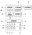
- FIG. 1 is a block diagram illustrating the configuration of a keyboard instrument 100 according to a first embodiment of the present disclosure.
- a keyboard instrument 100 is a musical instrument that a user uses to play music, and includes a keyboard mechanism 20 , a detection system 30 , a control system 40 and a sound emitting device 50 .
- the keyboard mechanism 20 has a keyboard 21 .
- the keyboard 21 is composed of a plurality of keys 211 including a plurality of white keys and a plurality of black keys.
- Each of the plurality of keys 211 is a performance operator that is displaced according to a performance operation by the user.
- the operation by the user is performance operation including key depression and key release.
- the detection system 30 detects user operations. Detection system 30 is an example of a "instrumental detection system.”
- the control system 40 generates performance data according to the results of detection by the detection system 30 . Performance data is time-series data representing performance operations by the user.
- FIG. 2 is a side view illustrating a specific configuration of the keyboard mechanism 20.
- FIG. A configuration focusing on an arbitrary one key 211 of the keyboard 21 is illustrated in FIG.
- Each key 211 of the keyboard 21 is supported by the support 12 with the support portion (balance pin) 11 as a fulcrum.
- the support 12 is a structure (frame) that supports each element of the keyboard instrument 100 .
- the tip of the key 211 is displaced in the vertical direction by key depression and key release by the user.
- the keyboard mechanism 20 also has a string 13 and a string-striking mechanism 22 for each key 211 .
- the string-striking mechanism 22 corresponding to each key 211 is an action mechanism that strikes the string 13 in conjunction with the displacement of the key 211 .
- a string 13 is installed for each pitch.
- the string-striking mechanism 22 includes a transmission mechanism 23 and a hammer 24 .
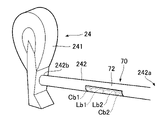
- FIG. 3 is a perspective view illustrating the configuration of the hammer 24.
- the hammer 24 comprises a hammer head 241 and a hammer shank 242, as illustrated in FIGS.
- Hammer shank 242 is an elongated structure having ends 242a and 242b. The end portion 242 a is pivotally supported by the transmission mechanism 23 .
- a hammer head 241 is fixed to the end portion 242b.
- the hammer shank 242 of the first embodiment is a shaft member having a curved outer peripheral surface. In the first embodiment, a cylindrical hammer shank 242 is illustrated.
- the transmission mechanism 23 in FIG. 2 rotates the hammer 24 in conjunction with the displacement of the key 211 according to the performance operation by the user.
- the transmission mechanism 23 is composed of a mechanical element such as a whipen, a jack, or a repetition lever. As shown by broken lines in FIG. 2 , the transmission mechanism 23 rotates the hammer shank 242 in conjunction with the displacement of the key 211 , and the hammer head 241 strikes the string 13 . That is, the hammer 24 moves within a range between the rest position shown in solid lines in FIG. 2 and the string-striking position shown in dashed lines in FIG. The rest position is where the hammer shank 242 abuts the stopper directly below.
- the string-striking position is the position at which the hammer head 241 strikes the string 13 .
- the hammer shank 242 (hammer 24) is a movable member that rotates in conjunction with key depression by the user.
- FIG. 4 is a block diagram illustrating the configuration of the detection system 30 and the control system 40.
- the detection system 30 includes multiple magnetic sensors 31 corresponding to different hammers 24 and a drive circuit 32 for driving each of the multiple magnetic sensors 31 .
- a magnetic sensor 31 corresponding to each hammer 24 is a sensor that detects the position of the hammer 24 .
- Each of the plurality of magnetic sensors 31 has a signal generation section 60 and a detected section 70 . That is, a set of the signal generating portion 60 and the detected portion 70 is installed for each hammer 24 .
- the detected part 70 is installed on the hammer 24 as illustrated in FIGS. Specifically, the detected part 70 is installed on the hammer shank 242 . Therefore, the detected portion 70 moves in conjunction with the performance operation of the key 211 by the user.
- the signal generator 60 is installed on the support 14 of the keyboard mechanism 20 .
- the support 14 is a structure fixed above the string-striking mechanism 22 .
- a signal generator 60 is installed at a portion of the support 14 facing the hammer shank 242 . Therefore, the signal generator 60 does not move even when the user operates the key 211 .
- FIG. 5 is a circuit diagram illustrating the electrical configuration of any one magnetic sensor 31.
- the signal generator 60 has an active resonance circuit 61 .
- the active resonance circuit 61 includes an input terminal T1, an output terminal T2, a resistive element R, a coil La, a capacitive element Ca1, and a capacitive element Ca2.
- One end of the resistance element R is connected to the input terminal T1, and the other end of the resistance element R is connected to one end of the capacitance element Ca1 and one end of the coil La.
- the other end of the coil La is connected to the output terminal T2 and one end of the capacitive element Ca2.
- the other end of the capacitive element Ca1 and the other end of the capacitive element Ca2 are grounded (Gnd).
- Coil La includes a first portion La1 and a second portion La2 connected in series with each other.
- the detected part 70 has a passive resonance circuit 71 .
- the passive resonance circuit 71 includes a capacitive element Cb and a coil Lb.
- the capacitive element Cb is composed of a capacitive element Cb1 and a capacitive element Cb2 which are connected in parallel with each other.
- Capacitive element Cb1 includes electrode Cb1-1 and electrode Cb1-2, and capacitive element Cb2 includes electrode Cb2-1 and electrode Cb2-2. Electrode Cb1-1 of capacitive element Cb1 and electrode Cb2-1 of capacitive element Cb2 are electrically connected to one end of coil Lb at connection point N1.
- the electrode Cb1-2 of the capacitive element Cb1 and the electrode Cb2-2 of the capacitive element Cb2 are electrically connected to the other end of the coil Lb at the connection point N2.
- the connection point N1 corresponds to one end of the coil Lb
- the connection point N2 corresponds to the other end of the coil Lb.
- Coil Lb includes a first portion Lb1 and a second portion Lb2 connected in series with each other.
- the capacitive element Cb2 may be composed of one capacitive element.
- the capacitive element Cb may be composed of three or more capacitive elements. That is, the specific form of the capacitive element Cb is arbitrary as long as the required capacitance can be secured.
- the resonance frequency of the active resonance circuit 61 and the resonance frequency of the passive resonance circuit 71 are set to the same frequency.
- the resonance frequency of the active resonance circuit 61 and the resonance frequency of the passive resonance circuit 71 may be different.
- the resonance frequency of the active resonance circuit 61 is set to a frequency obtained by multiplying the resonance frequency of the passive resonance circuit 71 by a predetermined constant.
- the signal generating section 60 includes the coil La
- the detected section 70 includes the coil Lb.
- the coil La and the coil Lb face each other with a space therebetween.
- the distance between the signal generating section 60 and the detected section 70 changes according to the position of the hammer shank 242 .
- the signal generating section 60 and the detected section 70 repeatedly approach and separate from each other in response to key depression and key release by the user.
- the drive circuit 32 in FIG. 4 generates a detection signal D corresponding to the distance between the coil La and the coil Lb.
- the coil La is an example of a "first coil”
- the coil Lb is an example of a "second coil”.
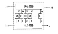
- FIG. 6 is a block diagram illustrating a specific configuration of the drive circuit 32.
- the drive circuit 32 comprises a supply circuit 321 and an output circuit 322 .
- the supply circuit 321 supplies the reference signal W to the input terminal T1 of the active resonance circuit 61 in each of the plurality of signal generators 60 .
- the supply circuit 321 is a demultiplexer that supplies the reference signal W to each of the plurality of signal generators 60 in a time division manner.
- the reference signal W is a signal whose level periodically fluctuates.
- a periodic signal having an arbitrary waveform such as a sine wave or a rectangular wave is used as the reference signal W, for example.
- the frequency of the reference signal W is sufficiently shorter than the length of time during which the reference signal W is supplied to one signal generator 60 . Also, the frequency of the reference signal W is set to a frequency substantially equal to the resonance frequencies of the active resonance circuit 61 and the passive resonance circuit 71 .
- the reference signal W is supplied to the coil La via the input terminal T1 and the resistive element R.
- a magnetic field is generated in the coil La by supplying the reference signal W.
- FIG. An induced current is generated in the coil Lb of the detected portion 70 by electromagnetic induction due to the magnetic field generated in the coil La. That is, a magnetic field is generated in the coil Lb in a direction that cancels out the change in the magnetic field of the coil La.
- the magnetic field generated in the coil Lb changes according to the distance between the coils La and Lb. Therefore, the detection signal d whose level fluctuates with an amplitude .delta. corresponding to the distance between the coil La and the coil Lb is output from the output terminal T2 of the signal generator 60.
- the detection signal d is a periodic signal whose level fluctuates at the same frequency as that of the reference signal W.
- FIG. As can be understood from the above description, the signal generation section 60 generates the detection signal d according to the distance between the detected section 70 and the coil La.
- the output circuit 322 in FIG. 6 is a multiplexer that generates the detection signal D by arranging the detection signals d sequentially output from each of the plurality of signal generation units 60 on the time axis. That is, the detection signal D is a signal whose level fluctuates with an amplitude ⁇ corresponding to the distance between the coil La and the coil Lb in the key 211 . Since the distance between the coil La and the coil Lb correlates with the position of the hammer 24 as described above, the detection signal D is expressed as a signal corresponding to each position of the plurality of hammers 24 .
- a detection signal D produced by the output circuit 322 is provided to the control system 40 . Note that the detection signal D may be supplied to the control system 40 after being rectified (half-wave rectified or full-wave rectified) and smoothed.
- the control system 40 in FIG. 4 generates performance data by analyzing the detection signal D supplied from the drive circuit 32 .
- the control system 40 is implemented by a computer system comprising a control device 41 , a storage device 42 , an A/D converter 43 and a tone generator device 44 .
- the control system 40 can be realized by a single device, or by a plurality of devices configured separately from each other.
- the control system 40 is realized as an electronic device mounted on the keyboard instrument 100, and also as an information device (for example, a smart phone or a tablet terminal) connected to the keyboard instrument 100 by wire or wirelessly.
- the control device 41 is composed of one or more processors that control each element of the keyboard instrument 100 .
- processors such as CPU (Central Processing Unit), SPU (Sound Processing Unit), DSP (Digital Signal Processor), FPGA (Field Programmable Gate Array), or ASIC (Application Specific Integrated Circuit)
- the control device 41 is configured by the following.
- the storage device 42 is a single or multiple memories that store programs executed by the control device 41 and data used by the control device 41 .
- the storage device 42 is composed of a known recording medium such as a magnetic recording medium or a semiconductor recording medium. Note that the storage device 42 may be configured by combining a plurality of types of recording media. Alternatively, a portable recording medium detachable from the keyboard instrument 100 or an external recording medium (for example, online storage) with which the keyboard instrument 100 can communicate may be used as the storage device 42 .
- the A/D converter 43 converts the detection signal D supplied from the drive circuit 32 from analog to digital.
- the control device 41 analyzes the position of each of the plurality of hammers 24 by analyzing the detection signal D converted by the A/D converter 43 .
- the control device 41 generates performance data representing temporal changes in the position of each hammer 24 and stores the performance data in the storage device 42 . That is, the performance by the user is recorded.
- the performance data is time-series data specifying the pitch played by the user and the intensity (velocity) of the performance.
- the playing strength of each pitch is set according to the speed at which the position of the hammer shank 242 corresponding to the pitch changes.
- the sound source device 44 generates an acoustic signal V representing the sound instructed by the control device 41 .
- the control device 41 instructs the sound source device 44 to produce sound corresponding to the performance data stored in the storage device 42 . Therefore, an acoustic signal V representing the sound corresponding to the user's past performance is generated.
- the tone generator device 44 generates an acoustic signal V corresponding to the pitch and intensity specified by the performance data.
- the control device 41 may implement the functions of the tone generator device 44 by executing a program stored in the storage device 42 .
- the sound emitting device 50 reproduces the sound represented by the acoustic signal V.
- the sound emitting device 50 is, for example, a speaker or headphones. Note that the sound emitting device 50 that is separate from the control system 40 may be connected to the control system 40 by wire or wirelessly.
- FIG. 7 is a plan view illustrating a specific configuration of the signal generator 60 corresponding to one hammer 24.
- FIG. FIG. 7 shows a plan view of the signal generation unit 60 as viewed from the hammer 24 side (specifically, vertically downward).
- 8 is a sectional view taken along line aa in FIG. 7.
- FIG. The vertical direction in FIG. 7 corresponds to the direction in which the keys 211 are arranged on the keyboard 21 .
- the horizontal direction in FIGS. 7 and 8 corresponds to the longitudinal direction of the key 211.
- the signal generator 60 is a circuit board having a substrate 62 on which an active resonance circuit 61 is installed.
- Base material 62 is a rigid insulating substrate having a surface Fa1 and a surface Fa2.
- the base material 62 is formed in a continuous elongated shape over the multiple keys 211 .
- the surface Fa1 and the surface Fa2 are mutually opposite surfaces.
- the surface Fa1 is the surface of the substrate 62 that faces the detected portion 70 .
- a surface Fa2 is the surface of the substrate 62 facing the support 14 .
- a conductive pattern 63 - 1 is formed on the surface Fa1 of the base material 62 .
- a conductive pattern 63-1 is formed by patterning a conductive film covering the entire surface Fa1.
- a conductive pattern 63-2 is formed on the surface Fa2 of the substrate 62. As shown in FIG.
- a conductive pattern 63-2 is formed by patterning a conductive film covering the entire surface Fa2.
- the conductive pattern 63-1 includes a first portion La1, a second portion La2, an input terminal T1, an output terminal T2, and a ground terminal Tg. As described with reference to FIG. 5, the reference signal W is supplied to the input terminal T1, and the detection signal d is output from the output terminal T2. The ground terminal Tg is grounded.
- the first portion La1 and the second portion La2 constitute the coil La of the active resonance circuit 61.
- Each of the first portion La1 and the second portion La2 is formed in a rectangular spiral shape.
- the spiral direction of the first portion La1 and the spiral direction of the second portion La2 are common.
- the planar shape of each of the first portion La1 and the second portion La2 is a spiral that rotates counterclockwise from the center to the outside.
- the first portion La1 and the second portion La2 are adjacent to each other. Specifically, a first portion La1 and a second portion La2 are arranged along the longitudinal direction of the key 211 .
- the conductive pattern 63-2 includes a connecting portion La3.
- the center of the first portion La1 is electrically connected to one end of the connection portion La3 via the conduction hole Ha1.
- the center of the second portion La2 is electrically connected to the other end of the connecting portion La3 via the conduction hole Ha2.
- Each of the through hole Ha1 and the through hole Ha2 is a through hole penetrating through the base material 62 .
- the first portion La1 and the second portion La2 are electrically connected to each other via the connecting portion La3.
- the first portion La1, the second portion La2, and the connection portion La3 constitute the coil La in FIG.
- a resistor element R, a capacitor element Ca1 and a capacitor element Ca2 are mounted on the surface Fa1 of the base material 62 .
- the resistive element R is mounted on the substrate 62 as an electronic component (chip resistor).
- capacitive element Ca1 and capacitive element Ca2 are mounted on substrate 62 as electronic components (chip capacitors).
- a magnetic field is generated in each of the first portion La1 and the second portion La2 due to the supply of current.
- the direction of the current flowing through the first portion La1 is opposite to the direction of the current flowing through the second portion La2. Therefore, as illustrated in FIG. 9, magnetic fields in opposite directions are generated in the first portion La1 and the second portion La2. That is, when a magnetic field in a first direction is generated in the first portion La1, a magnetic field in a second direction opposite to the first direction is generated in the second portion La2.
- a magnetic field directed from one of the first portion La1 and the second portion La2 to the other is formed, so that the diffusion of the magnetic field between the hammers 24 adjacent to each other is reduced. That is, magnetic field interference between two coils La adjacent to each other is reduced. Therefore, it is possible to generate the detection signal D that reflects the position of each of the plurality of hammers 24 with high accuracy.
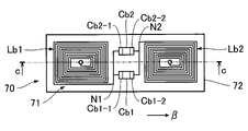
- FIG. 10 is a plan view illustrating a specific configuration of the detected portion 70 corresponding to one hammer 24.
- FIG. FIG. 10 shows a plan view of the detected portion 70 viewed from the signal generating portion 60 side.
- 11 is a cross-sectional view taken along line bb in FIG.
- the detected part 70 is a circuit board having a base material 72 on which a passive resonance circuit 71 is installed.
- the base material 72 is a flexible insulating substrate (film) formed in an elongated rectangular shape. That is, while the base material 62 of the signal generator 60 is a hard board, the base material 72 of the detected part 70 is a flexible board that can be deformed, for example, by bending or bending.
- the base material 72 is formed in a sheet shape from a resin material such as polyimide or polyester. 10 and 11, for the sake of convenience, a planar state in which the base material 72 is not deformed is illustrated.
- the base material 72 has a surface Fb1 and a surface Fb2.
- the surface Fb1 and the surface Fb2 are mutually opposite surfaces.
- each of surface Fb1 and surface Fb2 is planar.
- planar view observation from a direction perpendicular to the surface Fb1 of the base material 72 in an undeformed state is referred to as "planar view" for convenience.
- a capacitive element Cb (Cb1, Cb2) and a coil Lb (first portion Lb1 and second portion Lb2) are installed on the base material 72 .
- the coil Lb is positioned between the capacitive element Cb1 and the capacitive element Cb2 in plan view.
- the capacitive element Cb1 is placed near one end of the base material 72
- the capacitive element Cb2 is placed near the other end of the base material 72 .
- the coil Lb includes a first portion Lb1 and a second portion Lb2.
- the first portion Lb1 is located between the capacitive element Cb1 and the second portion Lb2 in plan view
- the second portion Lb2 is located between the capacitive element Cb2 and the first portion Lb1 in plan view.
- the capacitive element Cb1 and the capacitive element Cb2 are arranged between the first portion Lb1 and the second portion Lb2, for example.
- the influence of capacitive element Cb1 or capacitive element Cb2 on the magnetic field generated in coil Lb can be reduced.
- a conductive pattern 73 - 1 is formed on the surface Fb1 of the base material 72 .
- the conductive pattern 73-1 is formed by patterning a conductive film covering the entire surface Fb1.
- a conductive pattern 73-2 is formed on the surface Fb2 of the base material 72. As shown in FIG.
- the conductive pattern 73-2 is formed by patterning a conductive film covering the entire surface Fb2.
- the conductive patterns 73 (73-1, 73-2) are formed by patterning a conductive film formed on the base material 72, for example.
- the method of forming the conductive pattern 73 is not limited to the above examples.
- the conductive pattern 73 may be formed on the base material 72 by a printing technique such as an inkjet method.
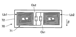
- FIG. 12 is a plan view of the conductive pattern 73-1 and the conductive pattern 73-2.
- the conductive pattern 73-1 includes a winding portion Lb1-1 of the first portion Lb1, a winding portion Lb2-1 of the second portion Lb2, an electrode Cb1-1 of the capacitive element Cb1, and an electrode Cb2- of the capacitive element Cb2. 1 and a wiring portion S1. That is, the winding portion Lb1-1, the winding portion Lb2-1, the electrode Cb1-1, the electrode Cb2-1, and the wiring portion S1 are collectively formed from the same layer in a common process.
- the winding portion Lb1-1 and the winding portion Lb2-1 are formed in a rectangular spiral shape in plan view. Specifically, the planar shape of the winding portion Lb1-1 is a spiral that turns counterclockwise from the center to the outer periphery. Similarly, the planar shape of the winding portion Lb2-1 is a spiral that turns counterclockwise from the center to the outer periphery. Electrode Cb1-1 and electrode Cb2-1 are formed in a rectangular shape in plan view. Electrode Cb1-1 is connected to winding portion Lb1-1 at connection point N1, and electrode Cb2-1 is connected to winding portion Lb2-1 at connection point N2. Moreover, the electrode Cb1-1 and the electrode Cb2-1 are electrically connected by the wiring portion S1. The wiring portion S1 is wiring extending on the surface Fb1 along the long side of the base material 72 .
- the conductive pattern 73-2 includes a winding portion Lb1-2 of the first portion Lb1, a winding portion Lb2-2 of the second portion Lb2, an electrode Cb1-2 of the capacitive element Cb1, and an electrode Cb2- of the capacitive element Cb2. 2 and a wiring portion S2. That is, the winding portion Lb1-2, the winding portion Lb2-2, the electrode Cb1-2, the electrode Cb2-2, and the wiring portion S2 are collectively formed from the same layer in a common process.
- the winding portion Lb1-2 and the winding portion Lb2-2 are formed in a rectangular spiral shape in plan view. Specifically, the planar shape of the winding portion Lb1-2 is a spiral that turns clockwise from the center to the outer periphery. Similarly, the planar shape of the winding portion Lb2-2 is a spiral that turns clockwise from the center to the outer periphery. Electrode Cb1-2 and electrode Cb2-2 are formed in a rectangular shape in plan view. Moreover, the electrode Cb1-2 and the electrode Cb2-2 are electrically connected by the wiring portion S2.
- the wiring portion S2 is a wiring extending on the surface Fb2 along the long side of the base material 72 .
- the winding portion Lb1-1 and the winding portion Lb1-2 overlap each other in plan view.
- the first portion Lb1 of the coil Lb is formed by connecting the winding portion Lb1-1 and the winding portion Lb1-2 to each other through the conduction hole Hb1.
- the winding portion Lb2-1 and the winding portion Lb2-2 overlap each other in plan view.
- the second portion Lb2 of the coil Lb is formed by connecting the winding portion Lb2-1 and the winding portion Lb2-2 to each other through the conduction hole Hb2. Further, the point between the winding portion Lb2-1 and the electrode Cb2-1 and the wiring portion S2 on the surface Fb2 are electrically connected to each other through the conduction hole Hb3.
- Each of the through holes Hb (Hb1-Hb3) is a through hole penetrating through the substrate 72 over the surface Fb1 and the surface Fb2.
- the coil Lb is composed of the conductive patterns 73 (73-1, 73-2) formed on the surfaces (Fb1, Fb2) of the base material 72.
- the direction of the current flowing through the first portion Lb1 and the direction of the current flowing through the second portion Lb2 are opposite. That is, in the state where the current in the direction ⁇ 1 flows in the first portion Lb1, the current in the direction ⁇ 2 opposite to the direction ⁇ 1 flows in the second portion Lb2. Therefore, as illustrated in FIG. 13, magnetic fields in opposite directions are generated in the first portion Lb1 and the second portion Lb2. According to the above configuration, since a magnetic field directed from one of the first portion Lb1 and the second portion Lb2 to the other is formed, diffusion of the magnetic field across the hammers 24 adjacent to each other is suppressed. That is, the magnetic field interference between the two hammers 24 adjacent to each other is reduced. Therefore, it is possible to generate the detection signal D that reflects the position of each of the plurality of hammers 24 with high accuracy.
- the direction ⁇ 1 is an example of the "first direction”
- the direction ⁇ 2 is an example of the "second direction”.
- each of the capacitive element Cb1 and the capacitive element Cb2 is composed of the conductive patterns 73 (73-1, 73-2) formed on the surface (Fb1, Fb2) of the base material 72. .
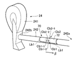
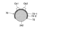
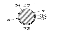
- FIG. 14 is a cross-sectional view of hammer shank 242 in a cross-section perpendicular to the axial direction.
- the detected portion 70 is installed on the hammer shank 242 with the surface Fb2 of the base material 72 facing the outer peripheral surface of the hammer shank 242 .
- the part to be detected 70 is bonded to the hammer shank 242 with an adhesive or an adhesive sheet, for example.
- the method for installing the detected part 70 on the hammer shank 242 is not limited to the above example.
- the part to be detected 70 may be joined to the hammer shank 242 by fasteners such as screws or staples.
- the detected part 70 is installed on the hammer shank 242 with the base material 72 curved along the curved outer peripheral surface of the hammer shank 242 .
- the part to be detected 70 is installed on the hammer shank 242 in a state in which the substrate 72 is curved in an arcuate shape having substantially the same diameter as the hammer shank 242 . That is, the detected portion 70 is wound around a part of the outer peripheral surface of the hammer shank 242 in the circumferential direction.
- the conductive pattern 73 - 1 and the conductive pattern 73 - 2 are curved along the outer peripheral surface of the hammer shank 242 together with the base material 72 .
- the detected portion 70 can be stably and firmly fixed to the hammer shank 242 .
- the first portion Lb1 and the second portion Lb2 of the coil Lb are arranged along the axial direction (that is, the longitudinal direction) of the hammer shank 242. That is, the first portion Lb1 of the coil Lb is positioned between the hammer head 241 side end portion 242b of the hammer shank 242 and the second portion Lb2. A second portion Lb2 of the coil Lb is positioned between the end portion 242a of the hammer shank 242 opposite to the hammer head 241 and the first portion Lb1.
- the first portion La1 of the coil La and the first portion Lb1 of the coil Lb are opposed to each other, and the second portion La2 of the coil La and the second portion Lb2 of the coil Lb are aligned. are opposed to each other.
- the coil Lb of the detected portion 70 is installed on the flexible base material 72 . Therefore, by appropriately deforming (for example, curving) the base material 72, the space required for installing the detected part 70 can be reduced compared to a configuration in which the base material 72 is hard. It is difficult to secure a sufficient space around the string-striking mechanism 22 of the keyboard instrument 100 (especially around the hammer shank 242). Therefore, the detection system 30 of the first embodiment, which can reduce the space required for installing the detected part 70 by adopting the flexible base material 72, is particularly suitable for the string-striking mechanism 22 of the keyboard instrument 100.
- the weight of the detected part 70 can be reduced compared to a configuration in which the base material 72 is hard. Therefore, the influence of the weight of the detected portion 70 on the motion of the hammer 24 is reduced. Specifically, the inertial force acting on the hammer 24 is reduced. Therefore, for example, even during a performance in which the user repeatedly presses keys in a short period of time (for example, playing repeatedly or trilling), it is possible to rotate the hammer 24 so as to follow the user's performance to a high degree. .
- the coil Lb curves together with the base material 72 . Therefore, compared to the case where the base material 72 is used without deformation, the characteristics of the magnetic field generated in the coil Lb (for example, the range or direction of the magnetic field) are variously set according to the degree of bending. That is, according to the first embodiment, there is also the advantage that the range of selection regarding the characteristics of the magnetic field generated in the coil Lb is expanded.
- the conductive patterns 73 (73-1, 73-2) formed on the flexible base material 72 constitute the coil Lb. Therefore, it is easier to form the coil Lb than, for example, a structure in which the coil Lb is formed by winding a conductive wire. Another advantage is that the coil Lb is easily deformed together with the base material 72 .
- the conductive patterns 73 (73-1, 73-2) formed on the flexible base material 72 allow the electrodes (Cb1-1, Cb1- 2, Cb2-1, Cb2-2) are constructed. Therefore, each capacitive element Cb (Cb1, Cb2) is easily deformed together with the base material 72 . That is, it is possible to reduce the possibility that excessive stress caused by the deformation of the base material 72 acts on the capacitive element Cb (Cb1, Cb2).
- the first portion Lb1 and the second portion Lb2 of the coil Lb are arranged along the longitudinal direction of the hammer shank 242. Therefore, for example, compared with the form in which the first portion Lb1 and the second portion Lb2 are arranged along the circumferential direction of the hammer shank 242, it is easier to secure a sufficient space for installing the coil Lb. Also, since the first portion Lb1 and the second portion Lb2 are arranged along the longitudinal direction of the hammer shank 242, the diffusion of the magnetic field between the adjacent hammers 24 is suppressed. Therefore, it is possible to generate the detection signal D that reflects the position of each of the plurality of hammers 24 with high accuracy.
- the first portion Lb1, the second portion Lb2, and the hammer shank 242 may be arranged along the circumferential direction.
- FIG. 15 is a plan view illustrating a specific configuration of the detected portion 70 in the second embodiment.
- 16 is a sectional view taken along line cc in FIG. 15.
- FIG. A detected portion 70 of the second embodiment includes a flexible base material 72 having a surface Fb1 and a surface Fb2, as in the first embodiment.
- a conductive pattern 73-1 is formed on the surface Fb1, and a conductive pattern 73-2 is formed on the surface Fb2.
- the conductive pattern 73-1 includes a winding portion Lb1-1 of the first portion Lb1 and a winding portion Lb2-1 of the second portion Lb2.
- Each of the winding portion Lb1-1 and the winding portion Lb2-1 is formed in a rectangular spiral that turns counterclockwise from the center to the outer circumference, as in the first embodiment.
- the conductive pattern 73-2 includes a winding portion Lb1-2 of the first portion Lb1 and a winding portion Lb2-2 of the second portion Lb2.
- Each of the winding portion Lb1- and the winding portion Lb2-2 is formed in a rectangular spiral that rotates clockwise from the center to the outer circumference, as in the first embodiment.
- FIG. 17 is a perspective view illustrating the configuration of the hammer 24 in the second embodiment.
- FIG. 18 is a cross-sectional view of a hammer shank 242 in the second embodiment.
- the capacitive element Cb1 and the capacitive element Cb2 of the first embodiment are composed of the conductive patterns 73 (73-1, 73-2) formed on the base material 72.
- FIG. Capacitive elements Cb (Cb1, Cb2) of the second embodiment are chip capacitors mounted on surface Fb1 of substrate 72, as illustrated in FIGS. Therefore, conductive pattern 73-1 does not include electrode Cb1-1 and electrode Cb2-1, and conductive pattern 73-2 does not include electrode Cb1-2 and electrode Cb2-2.
- the capacitive element Cb may be composed of one chip capacitor. Also, the capacitive element Cb may be composed of three or more chip capacitors. That is, the specific form of the capacitive element Cb is arbitrary as long as the required capacitance can be secured.
- the capacitive element Cb1 is an electronic component having an electrode Cb1-1 and an electrode Cb1-2. Each of electrode Cb1-1 and electrode Cb1-2 is bonded to surface Fb1 of base material 72 by a bonding technique such as soldering.
- the planar shape of the capacitive element Cb1 is a rectangular shape elongated in the direction ⁇ in which the electrodes Cb1-1 and Cb1-2 are arranged.
- capacitive element Cb2 is an electronic component having electrodes Cb2-1 and Cb2-2. Each of electrode Cb2-1 and electrode Cb2-2 is joined to surface Fb1 of substrate 72 by a joining technique such as soldering.
- the planar shape of the capacitive element Cb2 is a rectangular shape elongated in the direction in which the electrodes Cb2-1 and Cb2-2 are arranged. As understood from the above description, the direction ⁇ is the longitudinal direction of the capacitive element Cb (Cb1, Cb2).
- each of the capacitive element Cb1 and the capacitive element Cb2 is placed on the surface Fa1 of the base material 72 such that the longitudinal direction ⁇ of the capacitive element Cb is along the axial direction of the hammer shank 242.
- the axial direction of the hammer shank 242 corresponds to the longitudinal direction of the hammer shank 242 .
- the axial direction of the hammer shank 242 can be rephrased as the direction of the center axis of the curvature circle in the curve of the base material 72 .
- the “center axis of the circle of curvature” means the center axis of a virtual cylinder that contacts the inner peripheral surface of the base material 72 .
- the capacitive element Cb1 and the capacitive element Cb2 are arranged with a space therebetween along the circumferential direction of the hammer shank 242 . That is, the positions of the capacitive element Cb1 and the capacitive element Cb2 in the axial direction of the hammer shank 242 are common.
- the capacitive element Cb1 and the capacitive element Cb2 are composed of chip capacitors. Therefore, compared to the first embodiment in which the conductive patterns 73 (73-1, 73-2) formed on the base material 72 constitute the capacitive element Cb, it is easier to ensure the capacitance of the capacitive element Cb.
- FIG. 72 By the way, as an example in which a chip capacitor is used as the capacitive element Cb, as shown in FIG. 72 implementations are also envisioned. That is, the capacitive element Cb is installed such that the longitudinal direction ⁇ of the capacitive element Cb is along the circumferential direction of the hammer shank 242 .
- the configuration of FIG. 19 has a problem that the stress acting on the capacitive element Cb due to the curvature of the base material 72 is large.
- the longitudinal direction ⁇ of the capacitive element Cb is along the axial direction of the hammer shank 242
- compared with the configuration of FIG. can reduce the possibility of acting on
- the configuration of FIG. 19 is also included within the scope of the present disclosure.
- the third embodiment is a mode in which the magnetic sensor 31 of the detection system 30 is installed in the pedal mechanism 80 of the keyboard instrument 100 .
- the detection system 30 of the third embodiment detects the position of the pedal 81 that is displaced according to the performance operation of the user.
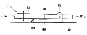
- the pedal mechanism 80 includes a pedal 81 operated by the user's foot, a support 82 supporting the pedal 81, an elastic body 83 urging the pedal 81 upward in the vertical direction, and a support positioned directly below the pedal 81. a body 84;
- the pedal 81 is an elongated structure having a front end portion 81a and a rear end portion 81b, and is a performance operator that is operated by a user's depression (that is, performance operation).
- the pedal 81 is a damper pedal, a sostenuto pedal or a soft pedal.
- the pedal mechanism 80 actually has a plurality of pedals 81, only one pedal 81 is shown in FIG. 20 for the sake of convenience.
- the detection system 30 detects the displacement of the pedal 81.
- the detected part 70 is installed on the bottom surface of the pedal 81 .
- the signal generating section 60 is installed on the support 84 so as to face the detected section 70 .
- the detected portion 70 is installed between the fulcrum of the pedal 81 by the support 82 and the front end portion 81 a of the pedal 81 . Therefore, the distance between the signal generating section 60 and the detected section 70 decreases as the user steps on the pedal 81 .
- the specific configurations of the signal generating section 60 and the detected section 70 are the same as in the first embodiment.
- FIG. 20 illustrates an embodiment in which the detected portion 70 is installed between the support 82 and the front end portion 81a of the pedal 81, but as illustrated in FIG. A detected portion 70 may be installed between the end portion 81b.
- the signal generating section 60 is installed on the support 84 so as to face the detected section 70 .
- the distance between the signal generating section 60 and the detected section 70 increases as the user steps on the pedal 81 .
- pedal mechanism 80 of the keyboard instrument 100 the pedal mechanism used for electric musical instruments such as electric stringed instruments (for example, an electric guitar) also has a structure similar to that of FIG. 20 or FIG. Adopted.
- a pedal mechanism used in electric musical instruments is an effect pedal that is operated by the user to adjust various sound effects, such as distortion or compressor.
- FIG. 22 is a side view illustrating the configuration of a keyboard mechanism 20 according to a fourth embodiment.
- the keyboard mechanism 20 of the fourth embodiment has a signal generator 91 and a detected part 92 for each key 211 in addition to the same elements as those of the first embodiment.
- the signal generator 91 is installed on the support 12
- the detected part 92 is installed on the lower surface 212 of the key 211 .
- a lower surface 212 of the key 211 is a flat surface.
- the configuration of the signal generator 91 is the same as that of the signal generator 60 in the first embodiment.
- the detected part 92 is a circuit board in which the passive resonance circuit 71 is installed on a substrate, like the detected part 70 in the first embodiment.
- the base material 72 of the detected part 70 in the first embodiment is composed of a flexible insulating substrate
- the base material of the detected part 92 in the fourth embodiment is composed of a hard insulating substrate. be done.
- the base material of the part to be detected 92 may be composed of a flexible insulating substrate.
- Each signal generation section 60 generates a detection signal d having an amplitude ⁇ corresponding to the distance between the signal generation section 60 and the detected section 70, as in the first embodiment.
- the control device 41 generates performance data according to the amplitude ⁇ of the detection signal d generated by each signal generating section 60 . Specifically, the control device 41 determines whether the user has pressed or released a key according to the amplitude ⁇ of the detection signal d.
- the fourth embodiment also achieves the same effect as the first embodiment. Note that the configuration of the second embodiment may be applied to the fourth embodiment.
- the configuration in which the detected part 70 is installed in the hammer shank 242 is illustrated, and in the third embodiment, the configuration in which the detected part 70 is installed in the pedal 81 is used.
- the movable member 200 on which the detected portion 70 is installed is not limited to the above exemplification.
- the detected portion 70 may be installed with the keys 211 forming the keyboard 21 as the movable members 200 .
- the type of instrument to which the detection system 30 according to the present disclosure is applied is arbitrary.
- the detection system 30 may detect an operator operated by a user when playing a wind instrument such as a woodwind instrument (eg clarinet or saxophone) or a brass instrument (eg trumpet or trombone).
- a wind instrument such as a woodwind instrument (eg clarinet or saxophone) or a brass instrument (eg trumpet or trombone).
- the target of detection by the detection system 30 is comprehensively expressed as the movable member 200 that displaces according to the user's operation (for example, performance operation).
- the movable member 200 includes not only performance operators such as keys or pedals 81 that are directly operated by the user, but also elements such as the hammers 24 that are displaced in conjunction with performance operations on the performance operators.
- the movable member 200 in the present disclosure is not limited to a member that displaces according to the performance operation by the user.
- the movable member 200 is comprehensively expressed as a member that can be displaced regardless of the trigger for generating displacement.
- the weight of the detected portion 70 is reduced as compared with the configuration in which the base material 72 is hard. Reduced impact.
- the detected portion 70 according to each of the above-described embodiments is particularly effectively used to detect the displacement of the movable member 200 (for example, the hammer 24 or the key 211) that reciprocates repeatedly. be.
- the detected part 70 may be installed above the hammer shank 242 (that is, the part near the signal generation part 60) in each of the above-described forms, but as illustrated in FIGS. 23 and 24 , the detected part 70 may be installed below the hammer shank 242 . That is, the part to be detected 70 may be installed at a portion of the outer peripheral surface of the hammer shank 242 opposite to the signal generating part 60 .
- the base material 72 curves along the outer peripheral surface of the hammer shank 242 while covering the lowest point of the cross section of the hammer shank 242 .
- the capacitive element Cb formed of the conductive pattern 73 was illustrated, but the detected portion 70 of the second embodiment in which the capacitive element Cb (Cb1, Cb2) is formed of chip capacitors can be similarly applied. may be installed below the hammer shank 242.
- the base material 72 may be wound around the entire circumferential direction of the movable member 200. That is, the base material 72 may be installed in a cylindrical shape. Moreover, both ends of the base material 72 may partially overlap on the surface of the movable member 200 .
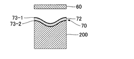
- the detected part 70 is installed on the cylindrical movable member 200, but the detected part 70 may be installed on the prismatic movable member 200 as illustrated in FIG.
- the base material 72 of the detected portion 70 is bent along the corners of the movable member 200 .
- the base material 72 is bent along the boundaries of the areas so that the areas of the base material 72 facing the side surfaces of the movable member 200 are in close contact with the side surfaces.
- the deformation of the base material 72 is not limited to the curved curved surface exemplified in each of the above embodiments, and includes any deformation such as bending or bending.
- the substrate 72 of the detected portion 70 is convexly curved toward the signal generating portion 60 (coil La), but as illustrated in FIG. A form curved concavely toward the generator 60 (coil La) is also envisioned.
- the detected part 70 may be embedded in the hammer shank 242 as illustrated in FIG. Specifically, the part to be detected 70 is inserted into the slit 242 c formed in the hammer shank 242 . Note that, for example, the detected portion 70 may be embedded in the hammer shank 242 under a configuration in which the hammer shank 242 is made of a hard resin material.
- FIG. 29 shows another example of the position where the detected part 70 is installed on the hammer 24.
- the hammer head 241 is composed of a long hammerwood 243, a hammer lining felt 244 provided at the tip of the hammerwood 243, and a hammer felt 245 covering the hammer lining felt 244. be done.
- the detected part 70 may be installed on the hammerwood 243 as in aspects Q1 to Q4 of FIG. Specifically, in aspect Q1, detected part 70 is installed at the rear end of hammerwood 243 . In mode Q2, detected part 70 is installed on the upper surface of hammerwood 243 . In aspects Q3 and Q4, detected portion 70 is installed between hammerwood 243 and hammer felt 245 .
- the detected part 70 may be installed on the hammer felt 245 as in aspects Q5 to Q8 of FIG.
- mode Q5 detected part 70 is installed on the outer peripheral surface of hammer felt 245 .
- mode Q6 detected part 70 is installed between hammer lining felt 244 and hammer felt 245 .
- detected portion 70 is embedded in hammer felt 245 . Specifically, the detected part 70 is inserted into a slit formed in the hammer felt 245 .
- the form in which the base material 72 of the detected part 70 is formed of a flexible film was exemplified. It may be formed of a substrate (rigid substrate). Further, in the above description, the configuration in which the coil Lb is installed on the surface of the base material 72 is illustrated, but a configuration in which the coil Lb of the detected portion 70 is wound around the hammer shank 242 is also assumed.
- the coil Lb may be configured by winding a conductive wire around the hammer shank 242, or the coil Lb may be configured by forming a conductive pattern on the outer peripheral surface of the hammer shank 242 by a printing technique such as an inkjet method. good too.
- FIG. 30 illustrates a mode in which the signal generation section 60 is installed below the hammer shank 242 .
- the coil La of the signal generating section 60 and the coil Lb of the detection target section 70 come closest to each other when the user does not press the key, and the coil La and the coil Lb are coupled together with the key pressing by the user. are separated from each other.
- the coil Lb includes the first portion Lb1 and the second portion Lb2. good too.
- the coil La may be composed of only one of the first portion La1 and the second portion La2.
- the coil Lb is constituted by the conductive patterns 73 (73-1, 73-2) formed on the base material 72, but the form of the coil Lb is not limited to the above examples.
- a coil for example, a chip coil
- the coil La may be formed by winding a conductive wire.
- the detected part 70 includes two layers of the conductive pattern 73, but the number of layers of the conductive pattern 73 is arbitrary.
- the capacitive element Cb (Cb1, Cb2) and the coil Lb may be composed of three or more layers of conductive patterns 73 .
- the coil Lb may be composed of a single layer.
- the coil Lb is installed between the capacitive element Cb1 and the capacitive element Cb2.
- Cb1 and capacitive element Cb2 may be placed between first portion Lb1 and second portion Lb2 of coil Lb.
- the capacitive element Cb1 and the capacitive element Cb2 are arranged in the circumferential or axial direction of the hammer shank 242, for example.
- the capacitive element Cb1 and the capacitive element Cb2 are arranged between the first portion Lb1 and the second portion Lb2 of the coil Lb.
- a coil Lb may be installed between Cb1 and capacitive element Cb2.
- the capacitive element Cb1 and the capacitive element Cb2 are arranged in the circumferential or axial direction of the hammer shank 242, for example.
- the keyboard instrument 100 including the strings 13, which are sound generating sources is illustrated, but the strings 13 may be omitted.
- the control device 41 supplies the performance data to the sound source device 44 in parallel with the generation of the performance data, thereby causing the sound emitting device 50 to reproduce the sound corresponding to the performance by the user.
- the string-striking mechanism 22 is used for the purpose of making the feel of key depression by the user closer to that of a natural musical instrument without executing string-striking.
- the keyboard instrument 100 including the tone generator device 44 was illustrated, but the tone generator device 44 may be omitted.
- the string-striking mechanism 22 strikes the string 13 according to the user's performance, thereby emitting sound corresponding to the user's performance.
- the detection system 30 is used to record the user's performance as performance data.
- the detection system 30 in each of the above-described forms is also used as an operation device that receives performance operations by the user. It does not matter whether or not there is an element that emits sound in the operation device (for example, the sound source device 44 or a sound source such as the string 13).
- an input device such as a MIDI (Musical Instrument Digital Interface) controller is exemplified as an operating device to which the detection system 30 is employed.
- the detection system 30 is comprehensively expressed as a system for detecting user's operations (especially performance operations such as key depression).
- a detection system includes a detected part installed on a movable member that is displaced according to a performance operation by a user, and a first coil that generates a magnetic field. and a signal generator that generates a detection signal according to the distance between the part and the first coil, and the detected part includes a flexible base fixed to the movable member, and and a second coil installed.
- the second coil of the part to be detected is installed on the flexible base material. Therefore, by appropriately deforming (for example, bending or curving) the base material, the space required for installing the detected part can be reduced compared to a configuration in which the base material is hard. In addition, compared to a structure in which the base material is hard, the weight of the detected part is reduced. Therefore, the influence of the weight of the detected part on the movement of the movable member can be reduced.
- the base material is fixed to the movable member in a deformed (for example, curved or bent) state.
- a deformed state when the detected part is installed.
- the base material may be fixed to the movable member in a deformed state, and the base material may be adjusted to the initial state (non-deformed state) after fixing.
- the direction of displacement of the second coil with respect to the first coil is arbitrary.
- the second coil moves along the winding axis of the second coil, or in conjunction with the displacement of the movable member, crosses the winding axis of the second coil.
- a mode is assumed in which the second coil moves in the direction to move. That is, it is a form in which the distance (relative positional relationship) between the first coil and the second coil changes in conjunction with the displacement of the movable member.
- the detected portion is installed on the movable member in a state where the base material is curved along the curved surface of the movable member.
- the detected portion can be stably and firmly fixed to the movable member.
- the direction of curvature of the base material is arbitrary.
- a form in which the base material is convexly curved toward the first coil or a form in which the base material is concavely curved toward the first coil is assumed.
- the base material is curved convexly toward the first coil.
- the base material is concavely curved toward the first coil.
- “Curved” of the substrate means a state in which an initially planar substrate is deformed into a curved surface.
- the form in which the base material is curved is exemplified, but the form in which the base material is deformed is not limited to the above examples.
- the detected part is installed on the angular surface of the movable member where the first surface and the second surface intersect with each other.
- the first portion of the substrate contacts or faces the first surface, and the second portion adjacent to the first portion contacts or faces the second surface, so that the linear boundary The substrate is folded along the lines.
- the second coil is a conductive pattern formed on the surface of the base material.
- the formation of the second coil is more difficult than the configuration in which the second coil is formed by winding a conductive wire, for example. is easy.
- the second coil easily deforms together with the base material.
- the second coil has a first portion in which current flows in a first direction and a current in a second direction opposite to the first direction. and a second portion. According to the above aspect, magnetic fields in opposite directions are generated in the first portion and the second portion of the second coil. Therefore, it is possible to suppress diffusion of the magnetic field from the second coil to the surroundings.
- the movable member is an elongated member, and the first portion and the second portion are arranged along the longitudinal direction of the movable member. According to the above aspect, it is easier to sufficiently secure the space for installing the second coil, compared to the configuration in which the first portion and the second portion are arranged along the circumferential direction of the movable member.
- the detected portion further includes a first capacitive element and a second capacitive element, and the first capacitive element and the second capacitive element are connected to the second coil. and the first portion and the second portion are arranged at intervals along the longitudinal direction of the movable member, and the first portion and the second portion are positioned between the first capacitive element and the second capacitive element. .
- the first capacitive element, the first portion, the second portion, and the second capacitive element are arranged along the longitudinal direction of the movable member. Therefore, there is an advantage that the detected part can be easily installed on the movable member.
- the detected part further includes a capacitive element connected to the second coil, and the electrodes of the capacitive element are connected to the surface of the base material.
- the movable member is an elongated member
- the detected part further includes a capacitive element connected to the second coil
- the capacitive element is The chip capacitor is mounted on the surface of the base material such that the longitudinal direction of the capacitive element is along the longitudinal direction of the movable member.
- the capacitive element is composed of the chip capacitor. Therefore, compared with the form in which the electrodes of the capacitor are formed by the conductive pattern formed on the surface of the base material, it is easy to sufficiently secure the capacitance of the capacitor.
- the capacitive element is installed so that the longitudinal direction of the capacitive element is along the central axis of the curvature circle of the base material.
- the movable member is a hammer shank that rotates in conjunction with key depression by the user.
- a detection signal representing the position of the hammer shank can be generated. It is difficult to secure a sufficient space around the string-striking mechanism of a keyboard instrument (especially around the hammer shank). Therefore, the embodiment of the present disclosure, in which the space required for installing the detected part can be reduced by adopting a flexible base material, is particularly suitable for a string striking mechanism of a keyboard instrument.
- a musical instrument includes a movable member that is displaced according to a performance operation by a user, a detection target part installed on the movable member, and a first coil that generates a magnetic field. , a signal generation unit that generates a detection signal corresponding to the distance between the detection target portion and the first coil, the detection target portion including a flexible base material fixed to the movable member; and a second coil mounted on the substrate.
- the movable member is a hammer shank that rotates in conjunction with key depression by the user. That is, the musical instrument according to aspect 11 is a keyboard instrument having a plurality of keys corresponding to different pitches.
- the second coil includes a first portion through which current flows in a first direction and a second portion through which current flows in a second direction opposite to the first direction. , the first portion and the second portion are arranged along the axial direction of the hammer shank.
- the first and second portions of the second coil are arranged along the axial direction of the hammer shank, the first and second portions are arranged along the circumferential direction of the hammer shank. Therefore, it is easy to sufficiently secure the space in which the second coil is installed.
- the portion to be detected further includes a capacitive element connected to the second coil, and the capacitive element has a longitudinal direction of the hammer shank.
- a chip capacitor mounted on the surface of the substrate along the axial direction. According to the above aspect, it is possible to reduce the possibility that excessive stress due to the curvature of the base material acts on the capacitor.
- the detected portion further includes a first capacitive element and a second capacitive element, and the first capacitive element and the second capacitive element are connected to the second coil. and are spaced apart from each other along the circumferential direction of the hammer shank.
- the first capacitive element, the second coil, and the second capacitive element are arranged along the longitudinal direction of the hammer shank. Therefore, there is an advantage that the part to be detected can be easily installed on the hammer shank.
Abstract
Description
図1は、本開示の第1実施形態に係る鍵盤楽器100の構成を例示するブロック図である。鍵盤楽器100は、利用者が音楽の演奏に使用する楽器であり、鍵盤機構20と検出システム30と制御システム40と放音装置50とを具備する。 A: First Embodiment FIG. 1 is a block diagram illustrating the configuration of a
第2実施形態を以下に説明する。なお、以下に例示する各構成において機能が第1実施形態と同様である要素については、第1実施形態の説明で使用した符号を流用して各々の詳細な説明を適宜に省略する。 B: Second Embodiment A second embodiment will be described below. In addition, in each configuration illustrated below, the reference numerals used in the description of the first embodiment are used for the elements whose functions are the same as those of the first embodiment, and the detailed description of each will be omitted as appropriate.
第1実施形態および第2実施形態においては、被検出部70がハンマ24に設置された形態を例示した。第3実施形態は、鍵盤楽器100のペダル機構80に検出システム30の磁気センサ31を設置した形態である。第3実施形態の検出システム30は、利用者の演奏操作に応じて変位するペダル81の位置を検出する。 C: Third Embodiment In the first embodiment and the second embodiment, the form in which the detected
図22は、第4実施形態における鍵盤機構20の構成を例示する側面図である。第4実施形態の鍵盤機構20は、第1実施形態と同様の要素に加えて信号生成部91と被検出部92とを鍵211毎に具備する。信号生成部91は支持体12に設置され、被検出部92は鍵211の下面212に設置される。鍵211の下面212は平坦面である。 D: Fourth Embodiment FIG. 22 is a side view illustrating the configuration of a
以上に例示した各態様に付加される具体的な変形の態様を以下に例示する。以下の例示から任意に選択された2以上の態様を、相互に矛盾しない範囲で適宜に併合してもよい。なお、以下の説明においては、利用者の演奏操作に応じて変位する部材を、便宜的に可動部材200と表記する。第1実施形態および第2実施形態のハンマシャンク242と第3実施形態のペダル81とは、可動部材200の一例である。 E: Modifications Examples of specific modifications added to the above-exemplified embodiments are given below. Two or more aspects arbitrarily selected from the following examples may be combined as appropriate within a mutually consistent range. In the following description, a member that is displaced according to the user's performance operation is referred to as a
以上に例示した形態から、例えば以下の構成が把握される。 F: Supplementary Note From the above-exemplified forms, for example, the following configuration can be grasped.
Claims (14)
- 利用者による演奏操作に応じて変位する可動部材に設置された被検出部と、
磁界を発生する第1コイルを含み、前記被検出部と前記第1コイルとの距離に応じた検出信号を生成する信号生成部とを具備し、
前記被検出部は、
前記可動部材に固定される可撓性の基材と、
前記基材に設置された第2コイルとを含む
楽器用検出システム。 a detected part installed on a movable member that is displaced according to a performance operation by a user;
a signal generation unit that includes a first coil that generates a magnetic field and generates a detection signal corresponding to the distance between the detection target unit and the first coil;
The part to be detected is
a flexible base fixed to the movable member;
a second coil mounted on the substrate; and a detection system for a musical instrument. - 前記被検出部は、前記可動部材の曲面状の表面に沿って前記基材が湾曲した状態で前記可動部材に設置される
請求項1の楽器用検出システム。 2. The musical instrument detection system according to claim 1, wherein the detected part is installed on the movable member in a state in which the base material is curved along the curved surface of the movable member. - 前記第2コイルは、前記基材の表面に形成された導電パターンである
請求項1または請求項2の楽器用検出システム。 3. The musical instrument detection system according to claim 1, wherein the second coil is a conductive pattern formed on the surface of the base material. - 前記第2コイルは、
第1方向に電流が流れる第1部分と、
前記第1方向とは反対の第2方向に電流が流れる第2部分とを含む
請求項1から請求項3の何れかの楽器用検出システム。 The second coil is
a first portion through which current flows in a first direction;
4. A musical instrument detection system according to any one of claims 1 to 3, comprising a second portion in which current flows in a second direction opposite to the first direction. - 前記可動部材は、長尺状の部材であり、
前記第1部分と前記第2部分とは、前記可動部材の長手方向に沿って配列する
請求項4の楽器用検出システム。 The movable member is an elongated member,
5. The musical instrument detection system of claim 4, wherein the first portion and the second portion are arranged along the length of the movable member. - 前記被検出部は、第1容量素子および第2容量素子をさらに含み、
前記第1容量素子および前記第2容量素子は、前記第2コイルに接続され、かつ、前記可動部材の長手方向に沿って相互に間隔をあけて配列し、
前記第1部分と前記第2部分とは、前記第1容量素子と前記第2容量素子との間に位置する
請求項5の楽器用検出システム。 The part to be detected further includes a first capacitive element and a second capacitive element,
the first capacitive element and the second capacitive element are connected to the second coil and arranged with a space therebetween along the longitudinal direction of the movable member;
6. The musical instrument detection system of claim 5, wherein the first portion and the second portion are located between the first capacitive element and the second capacitive element. - 前記被検出部は、前記第2コイルに接続される容量素子をさらに具備し、
前記容量素子の電極は、前記基材の表面に形成された導電パターンである
請求項1から請求項5の何れかの楽器用検出システム。 The part to be detected further comprises a capacitive element connected to the second coil,
6. The musical instrument detection system according to any one of claims 1 to 5, wherein the electrode of the capacitive element is a conductive pattern formed on the surface of the base material. - 前記可動部材は、長尺状の部材であり、
前記被検出部は、前記第2コイルに接続される容量素子をさらに具備し、
前記容量素子は、当該容量素子の長手方向が前記可動部材の長手方向に沿うように前記基材の表面に実装されたチップコンデンサである
請求項2の楽器用検出システム。 The movable member is an elongated member,
The part to be detected further comprises a capacitive element connected to the second coil,
3. The musical instrument detection system according to claim 2, wherein the capacitive element is a chip capacitor mounted on the surface of the base material such that the longitudinal direction of the capacitive element is along the longitudinal direction of the movable member. - 前記可動部材は、前記利用者による押鍵に連動して回動するハンマシャンクである
請求項1から請求項8の何れかの楽器用検出システム。 9. The musical instrument detection system according to any one of claims 1 to 8, wherein the movable member is a hammer shank that rotates in conjunction with key depression by the user. - 利用者による演奏操作に応じて変位する可動部材と、
前記可動部材に設置された被検出部と、
磁界を発生する第1コイルを含み、前記被検出部と前記第1コイルとの距離に応じた検出信号を生成する信号生成部とを具備し、
前記被検出部は、
前記可動部材に固定される可撓性の基材と、
前記基材に設置された第2コイルとを含む
楽器。 a movable member that is displaced according to a performance operation by a user;
a detected part installed on the movable member;
a signal generation unit that includes a first coil that generates a magnetic field and generates a detection signal according to the distance between the detection target unit and the first coil;
The part to be detected is
a flexible base fixed to the movable member;
and a second coil mounted on the substrate. - 前記可動部材は、前記利用者による押鍵に連動して回動するハンマシャンクである
請求項10の楽器。 11. The musical instrument according to claim 10, wherein the movable member is a hammer shank that rotates in conjunction with key depression by the user. - 前記第2コイルは、
第1方向に電流が流れる第1部分と、
前記第1方向とは反対の第2方向に電流が流れる第2部分とを含み、
前記第1部分と前記第2部分とは、前記ハンマシャンクの軸方向に沿って配列する
請求項11の楽器。 The second coil is
a first portion through which current flows in a first direction;
a second portion through which current flows in a second direction opposite to the first direction;
12. The musical instrument of claim 11, wherein the first portion and the second portion are arranged along the axial direction of the hammer shank. - 前記被検出部は、前記第2コイルに接続される容量素子をさらに含み、
前記容量素子は、当該容量素子の長手方向が前記ハンマシャンクの軸方向に沿うように前記基材の表面に実装されたチップコンデンサである
請求項11または請求項12の楽器。 The detected part further includes a capacitive element connected to the second coil,
13. The musical instrument according to claim 11, wherein the capacitive element is a chip capacitor mounted on the surface of the base material such that the longitudinal direction of the capacitive element is along the axial direction of the hammer shank. - 前記被検出部は、第1容量素子および第2容量素子をさらに含み、
前記第1容量素子および前記第2容量素子は、前記第2コイルに接続され、かつ、前記ハンマシャンクの周方向に沿って相互に間隔をあけて配列する
請求項11または請求項12の楽器。 The part to be detected further includes a first capacitive element and a second capacitive element,
13. A musical instrument according to claim 11 or 12, wherein the first capacitive element and the second capacitive element are connected to the second coil and are spaced apart from each other along the circumferential direction of the hammer shank.
Priority Applications (4)
| Application Number | Priority Date | Filing Date | Title |
|---|---|---|---|
| CN202280035004.6A CN117321676A (en) | 2021-05-18 | 2022-05-16 | Detection system for musical instrument and musical instrument |
| JP2023522648A JPWO2022244720A1 (en) | 2021-05-18 | 2022-05-16 | |
| EP22804631.4A EP4343752A1 (en) | 2021-05-18 | 2022-05-16 | Detection system for musical instrument, and musical instrument |
| US18/503,325 US20240078984A1 (en) | 2021-05-18 | 2023-11-07 | Detection system for musical instrument and musical instrument |
Applications Claiming Priority (2)
| Application Number | Priority Date | Filing Date | Title |
|---|---|---|---|
| JP2021-083888 | 2021-05-18 | ||
| JP2021083888 | 2021-05-18 |
Related Child Applications (1)
| Application Number | Title | Priority Date | Filing Date |
|---|---|---|---|
| US18/503,325 Continuation US20240078984A1 (en) | 2021-05-18 | 2023-11-07 | Detection system for musical instrument and musical instrument |
Publications (1)
| Publication Number | Publication Date |
|---|---|
| WO2022244720A1 true WO2022244720A1 (en) | 2022-11-24 |
Family
ID=84140460
Family Applications (1)
| Application Number | Title | Priority Date | Filing Date |
|---|---|---|---|
| PCT/JP2022/020348 WO2022244720A1 (en) | 2021-05-18 | 2022-05-16 | Detection system for musical instrument, and musical instrument |
Country Status (5)
| Country | Link |
|---|---|
| US (1) | US20240078984A1 (en) |
| EP (1) | EP4343752A1 (en) |
| JP (1) | JPWO2022244720A1 (en) |
| CN (1) | CN117321676A (en) |
| WO (1) | WO2022244720A1 (en) |
Citations (3)
| Publication number | Priority date | Publication date | Assignee | Title |
|---|---|---|---|---|
| JPH0348296A (en) * | 1990-05-16 | 1991-03-01 | Yamaha Corp | Electronic musical instrument |
| JP2001175262A (en) * | 1999-12-16 | 2001-06-29 | Yamaha Corp | Hammer detector and playing information acquiring device |
| WO2019122867A1 (en) | 2017-12-20 | 2019-06-27 | Sonuus Limited | Keyboard sensor systems and methods |
-
2022
- 2022-05-16 EP EP22804631.4A patent/EP4343752A1/en active Pending
- 2022-05-16 CN CN202280035004.6A patent/CN117321676A/en active Pending
- 2022-05-16 JP JP2023522648A patent/JPWO2022244720A1/ja active Pending
- 2022-05-16 WO PCT/JP2022/020348 patent/WO2022244720A1/en active Application Filing
-
2023
- 2023-11-07 US US18/503,325 patent/US20240078984A1/en active Pending
Patent Citations (4)
| Publication number | Priority date | Publication date | Assignee | Title |
|---|---|---|---|---|
| JPH0348296A (en) * | 1990-05-16 | 1991-03-01 | Yamaha Corp | Electronic musical instrument |
| JP2001175262A (en) * | 1999-12-16 | 2001-06-29 | Yamaha Corp | Hammer detector and playing information acquiring device |
| WO2019122867A1 (en) | 2017-12-20 | 2019-06-27 | Sonuus Limited | Keyboard sensor systems and methods |
| JP2021508399A (en) * | 2017-12-20 | 2021-03-04 | ソナス リミテッド | Keyboard sensor system and method |
Also Published As
| Publication number | Publication date |
|---|---|
| EP4343752A1 (en) | 2024-03-27 |
| CN117321676A (en) | 2023-12-29 |
| JPWO2022244720A1 (en) | 2022-11-24 |
| US20240078984A1 (en) | 2024-03-07 |
Similar Documents
| Publication | Publication Date | Title |
|---|---|---|
| US9373314B2 (en) | Installation structure for acoustic transducer | |
| US11922912B2 (en) | Instrument playing apparatus | |
| US9532124B2 (en) | Installation structure for acoustic transducer | |
| US9672802B2 (en) | Electronic drums | |
| WO2021193389A1 (en) | Displacement sensor and electronic musical instrument | |
| US20220277717A1 (en) | Detection system, musical instrument playing apparatus, and musical keyboard instrument | |
| WO2022075102A1 (en) | Circuit board and detection system | |
| US20230386442A1 (en) | Detection system and keyboard instrument | |
| WO2022244720A1 (en) | Detection system for musical instrument, and musical instrument | |
| JP7327646B2 (en) | Displacement sensor and performance control device | |
| JP2013250305A (en) | Pedal device for electronic percussion instrument | |
| WO2023228745A1 (en) | Detection system and musical instrument | |
| JP6597346B2 (en) | Drum head | |
| WO2023228746A1 (en) | Detection system and musical instrument | |
| WO2022244721A1 (en) | Musical instrument | |
| EP4064269A1 (en) | Stringed musical instrument and acoustic effect device | |
| JPWO2019150579A1 (en) | Signal output device | |
| JP2022151642A (en) | Stringed instrument and acoustic effect device | |
| JP2579230Y2 (en) | Electronic string instrument |
Legal Events
| Date | Code | Title | Description |
|---|---|---|---|
| 121 | Ep: the epo has been informed by wipo that ep was designated in this application |
Ref document number: 22804631 Country of ref document: EP Kind code of ref document: A1 |
|
| WWE | Wipo information: entry into national phase |
Ref document number: 2023522648 Country of ref document: JP |
|
| WWE | Wipo information: entry into national phase |
Ref document number: 2022804631 Country of ref document: EP |
|
| NENP | Non-entry into the national phase |
Ref country code: DE |
|
| ENP | Entry into the national phase |
Ref document number: 2022804631 Country of ref document: EP Effective date: 20231218 |