WO2021193389A1 - Displacement sensor and electronic musical instrument - Google Patents
Displacement sensor and electronic musical instrument Download PDFInfo
- Publication number
- WO2021193389A1 WO2021193389A1 PCT/JP2021/011266 JP2021011266W WO2021193389A1 WO 2021193389 A1 WO2021193389 A1 WO 2021193389A1 JP 2021011266 W JP2021011266 W JP 2021011266W WO 2021193389 A1 WO2021193389 A1 WO 2021193389A1
- Authority
- WO
- WIPO (PCT)
- Prior art keywords
- coil
- distance
- displacement sensor
- signal
- detected
- Prior art date
Links
- 238000006073 displacement reaction Methods 0.000 title claims abstract description 50
- 238000001514 detection method Methods 0.000 claims abstract description 70
- 230000007274 generation of a signal involved in cell-cell signaling Effects 0.000 claims abstract description 57
- 239000000758 substrate Substances 0.000 claims description 25
- 230000007246 mechanism Effects 0.000 description 19
- 238000010586 diagram Methods 0.000 description 13
- 238000012545 processing Methods 0.000 description 11
- 230000008859 change Effects 0.000 description 9
- 230000010365 information processing Effects 0.000 description 6
- 238000004804 winding Methods 0.000 description 5
- 230000006870 function Effects 0.000 description 4
- 238000009434 installation Methods 0.000 description 4
- 238000013016 damping Methods 0.000 description 3
- 238000000059 patterning Methods 0.000 description 3
- RYGMFSIKBFXOCR-UHFFFAOYSA-N Copper Chemical compound [Cu] RYGMFSIKBFXOCR-UHFFFAOYSA-N 0.000 description 2
- 238000013459 approach Methods 0.000 description 2
- 230000005540 biological transmission Effects 0.000 description 2
- 230000000052 comparative effect Effects 0.000 description 2
- 239000011889 copper foil Substances 0.000 description 2
- 230000007423 decrease Effects 0.000 description 2
- 238000009792 diffusion process Methods 0.000 description 2
- 239000002184 metal Substances 0.000 description 2
- 229910052751 metal Inorganic materials 0.000 description 2
- 238000000034 method Methods 0.000 description 2
- 230000004048 modification Effects 0.000 description 2
- 238000012986 modification Methods 0.000 description 2
- 230000000737 periodic effect Effects 0.000 description 2
- 125000002066 L-histidyl group Chemical group [H]N1C([H])=NC(C([H])([H])[C@](C(=O)[*])([H])N([H])[H])=C1[H] 0.000 description 1
- 230000009471 action Effects 0.000 description 1
- 230000008901 benefit Effects 0.000 description 1
- 238000006243 chemical reaction Methods 0.000 description 1
- 230000003247 decreasing effect Effects 0.000 description 1
- 230000005674 electromagnetic induction Effects 0.000 description 1
- 230000001771 impaired effect Effects 0.000 description 1
- 238000005259 measurement Methods 0.000 description 1
- 230000015654 memory Effects 0.000 description 1
- 238000009527 percussion Methods 0.000 description 1
- 239000004065 semiconductor Substances 0.000 description 1
Images


Classifications
-
- G—PHYSICS
- G01—MEASURING; TESTING
- G01D—MEASURING NOT SPECIALLY ADAPTED FOR A SPECIFIC VARIABLE; ARRANGEMENTS FOR MEASURING TWO OR MORE VARIABLES NOT COVERED IN A SINGLE OTHER SUBCLASS; TARIFF METERING APPARATUS; MEASURING OR TESTING NOT OTHERWISE PROVIDED FOR
- G01D5/00—Mechanical means for transferring the output of a sensing member; Means for converting the output of a sensing member to another variable where the form or nature of the sensing member does not constrain the means for converting; Transducers not specially adapted for a specific variable
- G01D5/12—Mechanical means for transferring the output of a sensing member; Means for converting the output of a sensing member to another variable where the form or nature of the sensing member does not constrain the means for converting; Transducers not specially adapted for a specific variable using electric or magnetic means
- G01D5/14—Mechanical means for transferring the output of a sensing member; Means for converting the output of a sensing member to another variable where the form or nature of the sensing member does not constrain the means for converting; Transducers not specially adapted for a specific variable using electric or magnetic means influencing the magnitude of a current or voltage
- G01D5/20—Mechanical means for transferring the output of a sensing member; Means for converting the output of a sensing member to another variable where the form or nature of the sensing member does not constrain the means for converting; Transducers not specially adapted for a specific variable using electric or magnetic means influencing the magnitude of a current or voltage by varying inductance, e.g. by a movable armature
- G01D5/2006—Mechanical means for transferring the output of a sensing member; Means for converting the output of a sensing member to another variable where the form or nature of the sensing member does not constrain the means for converting; Transducers not specially adapted for a specific variable using electric or magnetic means influencing the magnitude of a current or voltage by varying inductance, e.g. by a movable armature by influencing the self-induction of one or more coils
- G01D5/202—Mechanical means for transferring the output of a sensing member; Means for converting the output of a sensing member to another variable where the form or nature of the sensing member does not constrain the means for converting; Transducers not specially adapted for a specific variable using electric or magnetic means influencing the magnitude of a current or voltage by varying inductance, e.g. by a movable armature by influencing the self-induction of one or more coils by movable a non-ferromagnetic conductive element
- G01D5/2026—Mechanical means for transferring the output of a sensing member; Means for converting the output of a sensing member to another variable where the form or nature of the sensing member does not constrain the means for converting; Transducers not specially adapted for a specific variable using electric or magnetic means influencing the magnitude of a current or voltage by varying inductance, e.g. by a movable armature by influencing the self-induction of one or more coils by movable a non-ferromagnetic conductive element constituting a short-circuiting element
-
- G—PHYSICS
- G10—MUSICAL INSTRUMENTS; ACOUSTICS
- G10H—ELECTROPHONIC MUSICAL INSTRUMENTS; INSTRUMENTS IN WHICH THE TONES ARE GENERATED BY ELECTROMECHANICAL MEANS OR ELECTRONIC GENERATORS, OR IN WHICH THE TONES ARE SYNTHESISED FROM A DATA STORE
- G10H1/00—Details of electrophonic musical instruments
- G10H1/32—Constructional details
- G10H1/34—Switch arrangements, e.g. keyboards or mechanical switches specially adapted for electrophonic musical instruments
- G10H1/344—Structural association with individual keys
-
- G—PHYSICS
- G01—MEASURING; TESTING
- G01B—MEASURING LENGTH, THICKNESS OR SIMILAR LINEAR DIMENSIONS; MEASURING ANGLES; MEASURING AREAS; MEASURING IRREGULARITIES OF SURFACES OR CONTOURS
- G01B7/00—Measuring arrangements characterised by the use of electric or magnetic techniques
- G01B7/14—Measuring arrangements characterised by the use of electric or magnetic techniques for measuring distance or clearance between spaced objects or spaced apertures
-
- G—PHYSICS
- G01—MEASURING; TESTING
- G01D—MEASURING NOT SPECIALLY ADAPTED FOR A SPECIFIC VARIABLE; ARRANGEMENTS FOR MEASURING TWO OR MORE VARIABLES NOT COVERED IN A SINGLE OTHER SUBCLASS; TARIFF METERING APPARATUS; MEASURING OR TESTING NOT OTHERWISE PROVIDED FOR
- G01D5/00—Mechanical means for transferring the output of a sensing member; Means for converting the output of a sensing member to another variable where the form or nature of the sensing member does not constrain the means for converting; Transducers not specially adapted for a specific variable
- G01D5/12—Mechanical means for transferring the output of a sensing member; Means for converting the output of a sensing member to another variable where the form or nature of the sensing member does not constrain the means for converting; Transducers not specially adapted for a specific variable using electric or magnetic means
- G01D5/14—Mechanical means for transferring the output of a sensing member; Means for converting the output of a sensing member to another variable where the form or nature of the sensing member does not constrain the means for converting; Transducers not specially adapted for a specific variable using electric or magnetic means influencing the magnitude of a current or voltage
- G01D5/20—Mechanical means for transferring the output of a sensing member; Means for converting the output of a sensing member to another variable where the form or nature of the sensing member does not constrain the means for converting; Transducers not specially adapted for a specific variable using electric or magnetic means influencing the magnitude of a current or voltage by varying inductance, e.g. by a movable armature
- G01D5/204—Mechanical means for transferring the output of a sensing member; Means for converting the output of a sensing member to another variable where the form or nature of the sensing member does not constrain the means for converting; Transducers not specially adapted for a specific variable using electric or magnetic means influencing the magnitude of a current or voltage by varying inductance, e.g. by a movable armature by influencing the mutual induction between two or more coils
-
- G—PHYSICS
- G10—MUSICAL INSTRUMENTS; ACOUSTICS
- G10H—ELECTROPHONIC MUSICAL INSTRUMENTS; INSTRUMENTS IN WHICH THE TONES ARE GENERATED BY ELECTROMECHANICAL MEANS OR ELECTRONIC GENERATORS, OR IN WHICH THE TONES ARE SYNTHESISED FROM A DATA STORE
- G10H1/00—Details of electrophonic musical instruments
- G10H1/0008—Associated control or indicating means
-
- G—PHYSICS
- G10—MUSICAL INSTRUMENTS; ACOUSTICS
- G10H—ELECTROPHONIC MUSICAL INSTRUMENTS; INSTRUMENTS IN WHICH THE TONES ARE GENERATED BY ELECTROMECHANICAL MEANS OR ELECTRONIC GENERATORS, OR IN WHICH THE TONES ARE SYNTHESISED FROM A DATA STORE
- G10H1/00—Details of electrophonic musical instruments
- G10H1/02—Means for controlling the tone frequencies, e.g. attack or decay; Means for producing special musical effects, e.g. vibratos or glissandos
- G10H1/04—Means for controlling the tone frequencies, e.g. attack or decay; Means for producing special musical effects, e.g. vibratos or glissandos by additional modulation
- G10H1/053—Means for controlling the tone frequencies, e.g. attack or decay; Means for producing special musical effects, e.g. vibratos or glissandos by additional modulation during execution only
- G10H1/055—Means for controlling the tone frequencies, e.g. attack or decay; Means for producing special musical effects, e.g. vibratos or glissandos by additional modulation during execution only by switches with variable impedance elements
- G10H1/0555—Means for controlling the tone frequencies, e.g. attack or decay; Means for producing special musical effects, e.g. vibratos or glissandos by additional modulation during execution only by switches with variable impedance elements using magnetic or electromagnetic means
-
- G—PHYSICS
- G01—MEASURING; TESTING
- G01D—MEASURING NOT SPECIALLY ADAPTED FOR A SPECIFIC VARIABLE; ARRANGEMENTS FOR MEASURING TWO OR MORE VARIABLES NOT COVERED IN A SINGLE OTHER SUBCLASS; TARIFF METERING APPARATUS; MEASURING OR TESTING NOT OTHERWISE PROVIDED FOR
- G01D5/00—Mechanical means for transferring the output of a sensing member; Means for converting the output of a sensing member to another variable where the form or nature of the sensing member does not constrain the means for converting; Transducers not specially adapted for a specific variable
- G01D5/12—Mechanical means for transferring the output of a sensing member; Means for converting the output of a sensing member to another variable where the form or nature of the sensing member does not constrain the means for converting; Transducers not specially adapted for a specific variable using electric or magnetic means
- G01D5/14—Mechanical means for transferring the output of a sensing member; Means for converting the output of a sensing member to another variable where the form or nature of the sensing member does not constrain the means for converting; Transducers not specially adapted for a specific variable using electric or magnetic means influencing the magnitude of a current or voltage
- G01D5/20—Mechanical means for transferring the output of a sensing member; Means for converting the output of a sensing member to another variable where the form or nature of the sensing member does not constrain the means for converting; Transducers not specially adapted for a specific variable using electric or magnetic means influencing the magnitude of a current or voltage by varying inductance, e.g. by a movable armature
- G01D5/204—Mechanical means for transferring the output of a sensing member; Means for converting the output of a sensing member to another variable where the form or nature of the sensing member does not constrain the means for converting; Transducers not specially adapted for a specific variable using electric or magnetic means influencing the magnitude of a current or voltage by varying inductance, e.g. by a movable armature by influencing the mutual induction between two or more coils
- G01D5/2086—Mechanical means for transferring the output of a sensing member; Means for converting the output of a sensing member to another variable where the form or nature of the sensing member does not constrain the means for converting; Transducers not specially adapted for a specific variable using electric or magnetic means influencing the magnitude of a current or voltage by varying inductance, e.g. by a movable armature by influencing the mutual induction between two or more coils by movement of two or more coils with respect to two or more other coils
-
- G—PHYSICS
- G10—MUSICAL INSTRUMENTS; ACOUSTICS
- G10H—ELECTROPHONIC MUSICAL INSTRUMENTS; INSTRUMENTS IN WHICH THE TONES ARE GENERATED BY ELECTROMECHANICAL MEANS OR ELECTRONIC GENERATORS, OR IN WHICH THE TONES ARE SYNTHESISED FROM A DATA STORE
- G10H2220/00—Input/output interfacing specifically adapted for electrophonic musical tools or instruments
- G10H2220/155—User input interfaces for electrophonic musical instruments
- G10H2220/221—Keyboards, i.e. configuration of several keys or key-like input devices relative to one another
-
- G—PHYSICS
- G10—MUSICAL INSTRUMENTS; ACOUSTICS
- G10H—ELECTROPHONIC MUSICAL INSTRUMENTS; INSTRUMENTS IN WHICH THE TONES ARE GENERATED BY ELECTROMECHANICAL MEANS OR ELECTRONIC GENERATORS, OR IN WHICH THE TONES ARE SYNTHESISED FROM A DATA STORE
- G10H2220/00—Input/output interfacing specifically adapted for electrophonic musical tools or instruments
- G10H2220/155—User input interfaces for electrophonic musical instruments
- G10H2220/265—Key design details; Special characteristics of individual keys of a keyboard; Key-like musical input devices, e.g. finger sensors, pedals, potentiometers, selectors
- G10H2220/275—Switching mechanism or sensor details of individual keys, e.g. details of key contacts, hall effect or piezoelectric sensors used for key position or movement sensing purposes; Mounting thereof
-
- G—PHYSICS
- G10—MUSICAL INSTRUMENTS; ACOUSTICS
- G10H—ELECTROPHONIC MUSICAL INSTRUMENTS; INSTRUMENTS IN WHICH THE TONES ARE GENERATED BY ELECTROMECHANICAL MEANS OR ELECTRONIC GENERATORS, OR IN WHICH THE TONES ARE SYNTHESISED FROM A DATA STORE
- G10H2220/00—Input/output interfacing specifically adapted for electrophonic musical tools or instruments
- G10H2220/155—User input interfaces for electrophonic musical instruments
- G10H2220/405—Beam sensing or control, i.e. input interfaces involving substantially immaterial beams, radiation, or fields of any nature, used, e.g. as a switch as in a light barrier, or as a control device, e.g. using the theremin electric field sensing principle
- G10H2220/425—Radio control, i.e. input or control device involving a radio frequency signal
Definitions
- This disclosure relates to displacement sensors and electronic musical instruments.
- Patent Document 1 discloses a configuration in which the position of each key is detected by using a coil installed in a frame of a keyboard instrument and a metal plate installed in each key. In this configuration, when the metal plate is displaced by pressing the key, the current flowing through the coil changes. By detecting the current flowing through the coil, a detection signal that reflects the displacement of the key press is generated.
- one aspect of the present disclosure is to generate a detection signal that reflects the displacement of the movable member with high accuracy.
- the displacement sensor is installed on a movable member that is displaced according to an operation, and a detected portion including the first coil and a second coil facing the first coil. It includes a coil and includes a signal generation unit that generates a detection signal according to a relative position between the first coil and the second coil, and includes external dimensions of the first coil in the first direction and the first coil. It differs from the external dimensions of the first coil in the second direction orthogonal to the direction in a plan view.
- the displacement sensor is installed on a movable member that is displaced according to an operation, includes a detected portion including a first coil, and a second coil facing the first coil, and includes the first coil.
- a signal generation unit that generates a detection signal according to a relative position with the second coil is provided, and the first coil generates magnetic fields opposite to each other by supplying a current to the first coil.
- the second coil has a first portion and a second portion, and the second coil has a third portion and a fourth portion in which magnetic currents in opposite directions are generated by supplying an electric current to the second coil, and the first portion.
- the first distance between the center of the third portion and the center of the second portion exceeds the second distance between the center of the third portion and the center of the fourth portion.
- FIG. 5 is a cross-sectional view taken along the line Aa in FIG. It is explanatory drawing of the magnetic field and the like generated by the 1st coil of the detected part. It is a top view which illustrates the specific structure of the signal generation part.
- FIG. 8 is a cross-sectional view taken along the line BB in FIG.
- FIG. 1 is a block diagram illustrating a configuration of a keyboard instrument 100 to which a displacement sensor according to one embodiment of the present disclosure is applied.
- the keyboard instrument 100 is an electronic musical instrument including a keyboard 10, a detection system 15, an information processing device 30, and a sound emitting device 40.
- the keyboard 10 is composed of a plurality of keys 12 including a plurality of white keys and a plurality of black keys. Each of the plurality of keys 12 is a movable member that is displaced according to the performance operation by the user.
- the detection system 15 detects the displacement (position) of the key 12.
- the information processing device 30 generates an acoustic signal V according to the result of detection by the detection system 15.
- the acoustic signal V is a signal representing a musical tone having a pitch corresponding to the key 12 operated by the user.
- the sound emitting device 40 emits the sound represented by the acoustic signal V.
- a speaker or headphones are used as the sound emitting device 40.
- FIG. 2 is a block diagram illustrating a specific configuration of the keyboard instrument 100 by focusing on one key 12 of the keyboard 10.
- Each key 12 of the keyboard 10 is supported by the support member 14 with the fulcrum portion 13 as a fulcrum.
- the support member 14 is a structure that supports each element of the keyboard instrument 100.
- the end 121 of each key 12 is displaced in the vertical direction by the user pressing and releasing the key.
- the detection system 15 generates a detection signal D at a level corresponding to the position Z of the end portion 121 in the vertical direction for each of the plurality of keys 12.
- the position Z is represented by, for example, the amount of displacement of the end portion 121 with reference to the position of the end portion 121 in the released state in which no load acts on the key 12.
- the detection system 15 includes a displacement sensor 20 provided for each key 12 and a signal processing circuit 21 common to each key 12.
- the displacement sensor 20 is a position sensor that detects the position of each key 12, and includes a detected unit 50 and a signal generating unit 60.
- the signal generation unit 60 is installed on the support member 14.
- the detected unit 50 is installed on the key 12. Specifically, the detected unit 50 is installed on the bottom surface (hereinafter referred to as “installation surface”) 122 of the key 12.
- the detected unit 50 includes the first coil 51.
- the signal generation unit 60 includes a second coil 61. The first coil 51 and the second coil 61 face each other in the vertical direction with a distance from each other.
- the distance between the signal generation unit 60 and the detected unit 50 depends on the position Z of the end 121 of the key 12 being changed by pressing or releasing the key. Change.
- the signal processing circuit 21 generates a detection signal D at a level corresponding to the distance between the first coil 51 and the second coil 61.
- the information processing device 30 analyzes the position Z of each key 12 by analyzing the detection signal D supplied from the signal processing circuit 21.
- the information processing device 30 is realized by a computer system including a control device 31, a storage device 32, an A / D converter 33, and a sound source circuit 34.
- the A / D converter 33 converts the detection signal D supplied from the signal processing circuit 21 from analog to digital.
- the control device 31 is composed of a single or a plurality of processors that control each element of the keyboard instrument 100.
- the control device 31 is one or more types such as a CPU (Central Processing Unit), an SPU (Sound Processing Unit), a DSP (Digital Signal Processor), an FPGA (Field Programmable Gate Array), or an ASIC (Application Specific Integrated Circuit). It consists of a processor.
- the control device 31 analyzes the position Z of each key 12 by analyzing the detection signal D after conversion by the A / D converter 33. Further, the control device 31 instructs the sound source circuit 34 to pronounce a musical tone according to the position Z of each key 12.
- the sound source circuit 34 generates an acoustic signal V representing a musical tone instructed by the control device 31. That is, the sound source circuit 34 detects that the key has reached a predetermined position according to the voltage level ⁇ of the detection signal D, and starts generating the acoustic signal V. Then, for example, the volume of the acoustic signal V is controlled according to the speed change of the voltage level ⁇ .
- a musical sound corresponding to the performance operation by the user is emitted from the sound emitting device 40. Specifically, the musical sound is emitted when the user presses each key 12, and the musical sound is stopped when the key 12 is released.
- the storage device 32 is a single or a plurality of memories for storing a program executed by the control device 31 and data used by the control device 31.
- the storage device 32 is composed of a known recording medium such as a magnetic recording medium or a semiconductor recording medium.
- the storage device 32 may be configured by combining a plurality of types of recording media.
- a portable recording medium that can be attached to and detached from the keyboard instrument 100, or an external recording medium (for example, online storage) that the keyboard instrument 100 can communicate with may be used as the storage device 32.
- the control device 31 may realize the function of the sound source circuit 34 by executing the program stored in the storage device 32.
- the sound source circuit 34 or the control device 31 that realizes the function of the sound source circuit 34 functions as a sound control unit that generates an acoustic signal V corresponding to the voltage level ⁇ of the detection signal D.
- FIG. 3 is a circuit diagram illustrating an electrical configuration of the detected unit 50 and the signal generating unit 60 constituting the displacement sensor 20.
- the signal generation unit 60 includes an input terminal T1, an output terminal T2, a second coil 61, a capacitance element 62, a capacitance element 63, and a resistance element 64.
- the resonance circuit is composed of the second coil 61, the capacitance element 62, the capacitance element 63, and the resistance element 64.
- the input terminal T1 is connected to one end of the resistance element 64, and the other end of the resistance element 64 is connected to one end of the capacitance element 62 and one end of the second coil 61.
- the other end of the second coil 61 is connected to one end of the output terminal T2 and the capacitance element 63.
- the other end of the capacitance element 62 and the other end of the capacitance element 63 are grounded to the potential Gnd, which is a reference for zero voltage.
- the detected unit 50 includes the first coil 51 and the capacitive element 52.
- One end of the first coil 51 and one end of the capacitance element 52 are connected to each other, and the other end of the first coil 51 and the other end of the capacitance element 52 are connected to each other.
- a resonance circuit is formed by the first coil 51 and the capacitive element 52.
- the resonance frequency of the signal generation unit 60 is set according to the relationship with the resonance frequency of the detected unit 50, for example.
- the set resonance frequency of the signal generation unit 60 is set to, for example, a frequency substantially equal to the resonance frequency of the detected unit 50, or a frequency obtained by multiplying the resonance frequency of the detected unit 50 by a predetermined constant.
- the reference signal R is supplied to the input terminal T1 of the signal generation unit 60.
- the reference signal R is a voltage signal whose level fluctuates periodically.
- a periodic signal having an arbitrary waveform such as a sine wave is used as the reference signal R.
- the frequency of the reference signal R is set according to the relationship with the resonance frequency of the detected unit 50 and the like.
- the frequency of the reference signal R is substantially the same as the resonance frequency of the signal generation unit 60 and the detected unit 50.
- a magnetic field is generated in the second coil 61 by supplying a current corresponding to the reference signal R to the second coil 61.
- An induced current is generated in the first coil 51 by electromagnetic induction due to the magnetic field generated in the second coil 61. Therefore, a magnetic field in a direction that cancels the change in the magnetic field of the second coil 61 is generated in the first coil 51.
- the magnetic field generated in the first coil 51 changes according to the distance dr between the first coil 51 and the second coil 61. Therefore, the detection signal d of the voltage level ⁇ (peak-to-peak value) corresponding to the distance dr between the first coil 51 and the second coil 61 is output from the output terminal T2 of the signal generation unit 60.
- the detection signal d is a periodic signal whose level fluctuates in the same period as the reference signal R.
- FIG. 4 is a block diagram illustrating a specific configuration of the signal processing circuit 21.
- the signal processing circuit 21 includes a supply circuit 22 and an output circuit 23.
- the supply circuit 22 supplies the reference signal R to each of the input terminals T1 of the plurality of signal generation units 60.
- the supply circuit 22 supplies the reference signal R to each signal generation unit 60 in a time-division manner.
- the supply circuit 22 is a demultiplexer that sequentially selects each of the plurality of signal generation units 60 and supplies the reference signal R to the selected signal generation unit 60. That is, the reference signal R is supplied to each of the plurality of signal generation units 60 in a time-division manner.
- the period of the reference signal R is sufficiently shorter than the time length of the period during which the supply circuit 22 selects one signal generation unit 60.
- the output circuit 23 generates the detection signal D by arranging the detection signals d sequentially output from each of the plurality of signal generation units 60 on the time axis. That is, the detection signal D is a signal indicating the signal of the voltage level ⁇ corresponding to the distance dr between the first coil 51 and the second coil 61 in each key 12 in a time division manner. As described above, since the distance dr between the first coil 51 and the second coil 61 correlates with the position Z of each key 12, the detection signal D is a signal corresponding to each position Z of the plurality of keys 12. That is, when viewed with one key 12, the detection signal d is expressed as a signal corresponding to the relative position between the first coil 51 and the second coil 61 facing the first coil 51.
- the detection signal D generated by the output circuit 23 is supplied to the information processing device 30.
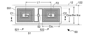
- FIG. 5 is a plan view showing a specific configuration of the detected unit 50, and is a view of the detected unit 50 as viewed from the signal generation unit 60 side.
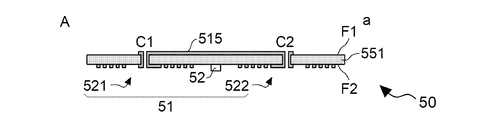
- FIG. 6 is a cross-sectional view taken along the line Aa in FIG.
- the detected unit 50 includes a substrate 551 and wiring patterns provided on the surfaces F1 and F2 of the substrate 551.
- the substrate 551 is a rectangular plate-shaped member having an insulating property.
- the surface F1 of the detected portion 50 is a surface attached to the installation surface 122 of the key 12.
- the wiring pattern of the detected portion 50 is formed by patterning a conductive layer such as a copper foil provided on the surfaces F1 and F2 of the substrate 551.
- the vertical direction is the direction in which a plurality of keys 12 are arranged, and the horizontal direction is the longitudinal direction of one key 12.
- the width Bw of the detected portion 50 attached to the installation surface 122 of the key 12 is equal to or less than the width Kw of one key 12.
- the surface F2 is a surface opposite to the surface F1. Therefore, the surface F2 faces the signal generation unit 60.
- the first coil 51 of the detected portion 50 is composed of a first portion 521 and a second portion 522.
- the first portion 521 and the second portion 522 are a part of the wiring pattern formed on the surface F2 of the substrate 551.
- the first portion 521 is a portion formed in a spiral shape.
- the second portion 522 is a portion formed in substantially the same shape as the first portion 521. That is, the second portion 522 is formed in a spiral shape in the same direction as the winding direction of the first portion 521.
- the spiral center of the first portion 521 is the via C1
- the spiral center of the second portion 522 is the via C2.
- the via C1 and the via C2 are conducted by the wiring pattern 515 of the surface F1.
- the straight line extending from the via C1 is bent by about 90 degrees and spreads outward.
- the outer shape of the first portion 521 is rectangular.
- the straight line extending from the via C2 is bent by about 90 degrees and spreads outward.
- the outer shape of the second portion 522 is rectangular.
- the outer shape of the first portion 521 and the second portion 522 is rectangular.
- the external dimension COL in the long side direction of the substrate 551 and the external dimension COW in the short side direction of the substrate 551 are shown.
- the external dimension COW corresponds to the dimension (size) of the first coil 51 in the short side direction of the substrate 551.
- the external dimension COW of each of the first portion 521 and the second portion 522 is equal to or less than the dimension Bw of the substrate 551 in the short side direction.
- the long side direction of the substrate 551 coincides with the arrangement direction of the first portion 521 and the second portion 522, that is, the longitudinal direction of the key 12.
- the short side direction of the substrate 551 coincides with the direction orthogonal to the arrangement direction of the first portion 521 and the second portion 522, that is, the width direction of the key 12.
- the via C1 is located at the center of the first portion 521. This center is the point where the diagonal lines of the rectangle, which is the outer shape of the first portion 521, intersect.
- the via C2 is located in the center of the second portion 522. This center is the point where the diagonal lines of the rectangle, which is the outer shape of the second part 522, intersect.
- the distance between the center of the first portion 521 (via C1) and the center of the second portion 522 (via C2) is defined as L1.
- the distance L1 is an example of the first distance.
- a capacitance is provided between the other end of the first portion 521 when the via C1 of the first portion 521 is used as one end and the other end of the second portion 522 when the via C2 of the second portion 522 is used as one end.
- the element 52 is mounted. Therefore, the equivalent circuit of the detected unit 50 has a configuration in which the capacitance elements 52 are connected to both ends of the first coil 51 as shown in FIG.
- the first portion 521 and the second portion 522 have the same dimensions and the same shape, but the present invention is not limited to this. For example, the shape or dimensions may differ between the first portion 521 and the second portion 522.
- planar shape of one or both of the first portion 521 and the second portion 522 may be a rectangular shape in which the vertical direction in FIG. 5 is the longitudinal direction and the horizontal direction in FIG. 5 is the lateral direction.
- planar shape of the first coil 51 is not limited to the shape including the first portion 521 and the second portion 522. That is, the first coil 51 may be composed of one winding portion.
- FIG. 8 is a plan view showing a specific configuration of the signal generation unit 60, and is a view of the signal generation unit 60 as viewed from the detected unit 50 side. Further, FIG. 9 is a cross-sectional view taken along the line BB in FIG.
- the signal generation unit 60 includes a substrate 651 and wiring patterns provided on the surfaces F3 and F4 of the substrate 651.
- the substrate 651 is a plate-shaped member having an insulating property.
- the surface F4 of the signal generation unit 60 faces the support member 14.
- the surface F3 is a surface opposite to the surface F4 and faces the detected portion 50.
- the wiring pattern is formed by patterning a conductive layer such as a copper foil provided on the surfaces F3 and F4 of the substrate 651.
- the vertical direction in FIG. 8 is the direction in which a plurality of keys 12 (not shown in FIG. 8) are arranged.
- the left-right direction in FIG. 8 is the longitudinal direction of one key 12.
- the longitudinal direction of the key 12 is a direction from the tip end side (performer side) of the key 12 toward the root side of the key 12.
- the second coil 61 of the signal generation unit 60 is composed of a third portion 621 and a fourth portion 622.
- the third portion 621 and the fourth portion 622 are a part of the wiring pattern formed on the surface F3.
- the third portion 621 is a portion formed in a substantially square shape and in a spiral shape.
- the fourth portion 622 is a portion formed in substantially the same shape as the third portion 621. That is, the fourth portion 622 is formed in a spiral shape in the same direction as the winding direction of the third portion 621.
- the spiral center of the third portion 621 is the via C11, and the spiral center of the fourth portion 622 is the via C12.
- the via C11 and the via C12 are conducted by the wiring pattern 612 of the surface F4.
- the third portion 621 and the fourth portion 622 have the same dimensions and the same shape, but the present invention is not limited to this.
- the dimensions may differ between the third portion 621 and the fourth portion 622.
- the third portion 621 and the fourth portion 622 may have different shapes from each other.
- the planar shape of the second coil 61 is not limited to the shape including the third portion 621 and the fourth portion 622. That is, the second coil 61 may be composed of one winding portion.
- the outer shape of the third portion 621 is substantially square.
- the outer shape of the fourth portion 622 is substantially square.
- the direction of one side of the square, which is the outer shape of the third portion 621 and the fourth portion 622, coincides with the longitudinal direction of the key 12, and the direction orthogonal to the one side coincides with the width direction of the key 12.
- B2 be the dimension (external dimension) of one side of the square.
- the via C11 is located at the center of the third portion 621, and the via C12 is located at the center of the fourth portion 622.
- the center here is the center of the coil in a plan view, is the point where the diagonal lines intersect in the case of a square or rectangle, and is the center of the outer circle in the case of a circle.
- the distance between the center of the third portion 621 (via C11 in the present embodiment) and the center of the fourth portion 622 (via C12 in the present embodiment) is L2.
- the distance L2 is an example of the second distance.
- the portion of the wiring pattern of the surface F3 other than the second coil 61 is wiring for connecting the capacitance element 62, the capacitance element 63, the resistance element 64, the input terminal T1 and the output terminal T2.
- the reference signal R is supplied to the input terminal T1 from the supply circuit 22, and the detection signal d of the voltage level ⁇ corresponding to the distance dr between the first coil 51 and the second coil 61 is supplied from the output terminal T2. Is output.
- the first portion 521 and the third portion 621 face each other, and the second portion 522 and the fourth portion 622 face each other.
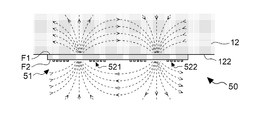
- FIG. 7 is a diagram showing an example of the magnetic field direction generated by the detected unit 50.
- FIG. 10 is a diagram showing an example of the magnetic field direction generated by the signal generation unit 60.
- magnetic fields in opposite directions are generated in the third portion 621 and the fourth portion 622.
- a plurality of keys 12 are arranged in the direction perpendicular to the paper surface of FIG. Therefore, the magnetic fields generated in the opposite directions in the third portion 621 and the fourth portion 622 reduce the diffusion of the magnetic fields generated in the signal generation unit 60 facing each key 12 adjacent to each other.
- a detection signal D that accurately reflects each position Z of the plurality of keys 12 is generated.
- FIG. 10 a case where a counterclockwise current flows through the third portion 621 and a clockwise current flows through the fourth portion 622 is illustrated in FIG. Similarly, when a clockwise current flows through the third portion 621 and a counterclockwise current flows through the fourth portion 622, the direction of the magnetic field is opposite.
- the third portion 621 and the fourth portion 622 of the second coil 61 in the signal generation unit 60 are formed by patterning the conductive layer on the surface F4. Therefore, for example, as compared with a configuration in which the second coil 61 is formed by winding a conductive wire, there is an advantage that the second coil 61 can be easily manufactured and handled.
- the first coil 51 is generated by the second coil 61.
- a magnetic field in a direction that prevents the magnetic field from decreasing that is, a magnetic field in the same direction as the magnetic field generated by the second coil 61
- a current is induced in the first coil 51 according to the magnetic field in the same direction as the magnetic field generated by the second coil 61. For example, when the first coil 51 of the detected unit 50 moves away from the second coil 61 in a state where the magnetic field in the direction shown in FIG.
- the magnetic field generated by the second coil 61 is used.
- a magnetic field in the opposite direction that is, a magnetic field as shown in FIG. 7, is generated in the first coil 51.
- the first coil 51 approaches the second coil 61 in a state where the magnetic field in the direction shown in FIG. 10 is generated by the second coil 61, and the magnetic field in the direction opposite to the direction shown in FIG. 10 is generated.
- a current flows clockwise in the first portion 521 of the first coil 51 and a current flows in the second portion 522. Flows counterclockwise.
- the output characteristic is the relationship between the distance dr between the first coil 51 and the second coil 61 and the voltage level ⁇ of the detection signal d.
- the linearity of the output characteristic means that the relationship of the voltage level ⁇ with respect to the distance dr is close to the proportional relationship.
- the detection distance means the width of the range (detection range) of the distance dr in which the voltage level ⁇ changes significantly with respect to the change in the distance dr. That is, the detection distance means the range of the distance dr reflected in the voltage level ⁇ .
- the distance L1 (first distance) between the center of the first portion 521 and the center of the second portion 522 is the center of the third portion 621 and the fourth portion 622. It exceeds the distance L2 (second distance) from the center of.
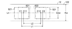
- FIG. 11 is a plan view showing the positional relationship between the first coil 51 and the second coil 61 in a state where the detected unit 50 is attached to the installation surface 122 of the key 12 and the signal generation unit 60 is installed on the support member 14. Is. Specifically, FIG. 11 shows the first portion 521 and the second portion 522 of the first coil 51 and the third portion 621 and the fourth portion 622 of the second coil 61 from the detected unit 50 in the above state. It is a top view when it sees through toward a signal generation part 60.
- Vias C1, C2, C11 and C12 are located on a straight line Ln along the longitudinal direction of the key 12. Further, vias C11 and C12 are located between vias C1 and C2.
- the distance L1 between the center of the first portion 521 and the center of the second portion 522 in the detected unit 50 is the center of the third portion 621 and the fourth portion 622 in the signal generation unit 60. It exceeds the distance L2 from the center of. Therefore, first, the effectiveness of the configuration in which the distance L1 exceeds the distance L2 will be described.
- the output characteristics are compared between the configuration A and the configuration B in which the distance L1 and the distance L2 are different in magnitude.
- the configuration A has a configuration in which the distance L1 in the first coil 51 exceeds the distance L2.
- the configuration B has a configuration in which the distance L1 in the first coil 51 is less than the distance L2.
- the distance L1 is L2 ⁇ 120% shown in FIG. 8
- the distance L1 is L2 ⁇ 80%.
- the external dimensions COL and COW in FIG. 12 and the external dimensions COL and COW in FIG. 13 have a length of the external dimensions B2 ⁇ 70% shown in FIG.
- the signal generation unit 60 in this comparison uses the configuration shown in FIG.
- FIG. 14 is a diagram showing the output characteristics of the displacement sensor 20 in the configuration A and the configuration B.
- the vertical axis is the voltage level ⁇ [V] of the detection signal d
- the horizontal axis is the distance according to the position of the displacement Z, specifically, the distance dr between the first coil 51 and the second coil 61. Is.
- the solid line shows the output characteristic of the configuration A shown in FIG. 12, and the broken line shows the output characteristic of the configuration B shown in FIG.
- the output voltage changes in the direction of increasing even if the distance dr exceeds 10 mm, whereas in the configuration B, the output voltage does not change when the distance dr exceeds 8 mm (it becomes a substantially constant value). ).
- the range of the distance dr at which the output change of the detection signal d can be obtained is wider than that of the broken line configuration B, that is, the displacement sensor 20 detects it. It can be seen that the range that can be done is wide. In other words, it can be said that the solid line configuration A has higher linearity in output characteristics than the broken line configuration B.
- the outer shapes of the first portion 521 and the second portion 522 in the detected unit 50 are not the square shown in FIG. 12 but the key 12 It is a rectangle extending in the longitudinal direction of.
- the region that functions as a coil is wide in the first portion 521 and the second portion 522. Therefore, in the present embodiment, the outer shapes of the first portion 521 and the second portion 522 of the detected portion 50 are rectangular along the longitudinal direction of the key 12. Specifically, in the present embodiment, the external dimension COL of each of the first portion 521 and the second portion 522 exceeds the external dimension COW. Specifically, in the present embodiment, the dimensional ratio of the external dimension COW and the external dimension COL is 7:10 in each of the first portion 521 and the second portion 522.
- FIG. 15 is a diagram showing output characteristics when the ratio (%) of the distance L1 with respect to the distance L2 is changed to 100%, 120%, 140%, and 160%.
- the voltage level ⁇ on the vertical axis is normalized so that the minimum value is “0” and the maximum value is “1” for comparison.
- the signal generation unit 60 in this study uses the configuration shown in FIG.
- the index indicating linearity (for example, the squared value of R) is highest when the distance L1 is L2 ⁇ 120%, and the lowest is when the distance L1 is L2 ⁇ . It is at 160%. Therefore, from the viewpoint of ensuring linearity, the distance L1 is preferably a numerical value within a range including a value before and after 120% with respect to the distance L2. Specifically, the distance L1 is set to a numerical value within a range (L2 ⁇ L1 ⁇ 1.4 ⁇ L2) that exceeds 100% with respect to the distance L2 and is 140% or less.
- the distance L1 is set to be within the above range with respect to the distance L2 in this way, the magnetic field generated in the second coil 61 is appropriately reduced to reach the first coil 51, so that the output characteristic of the detection signal d Linearity is increased. Further, when the distance L1 is set to be within the above range with respect to the distance L2, even if the position of the first coil 51 with respect to the second coil 61 is displaced, it is compared with the case where it is set to be outside the above range. , The linearity of the output characteristics is not impaired.
- FIG. 16 is a diagram showing output characteristics when the resistance value of the resistance element 64 in the circuit of FIG. 3 is changed stepwise. In FIG. 16, the output characteristics are shown for each case where the resistance value of the resistance element 64 is changed in six ways of 0, 100, 200, 300, 400 and 500 ⁇ .
- the voltage level ⁇ of the detection signal d becomes maximum when the distance dr slightly exceeds 5 mm, and then the distance dr increases. On the other hand, the voltage level ⁇ is lowered. Therefore, as the detection range, only a narrow range of about 1 to 5 mm can be used. However, when the resistance element 64 of 100 ⁇ is used so as to lower the Q value, the voltage level ⁇ of the detection signal d gradually increases with the increase of the distance dr even in the range where the distance dr exceeds 5 mm. ..
- the distance dr is in a small range (for example, 1 to 3 mm), a large range (for example, 8 to 10 mm), and an intermediate range (for example, 4 to 6 mm).
- the change width of the voltage level ⁇ becomes smaller.
- the Q value of the resistance element 64 in the signal generation unit 60 increases, the Q value decreases and the linearity of the output characteristic increases. That is, the detection distance can be increased.
- a resistance element as a damping resistor is not installed in the detected portion 50. This is because sufficient detection characteristics can be obtained without lowering the Q value.
- a resistance element as a damping resistor may be installed in the detected unit 50.
- the frequency of the reference signal R supplied to the input terminal T1 is set to a maximum of 2% from the resonance frequency of the detected unit 50 (that is, the resonance frequency). (From 98% to 100%), more preferably about 1% lower than the resonance frequency of the detected unit 50.
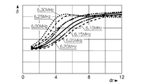
- the resonance frequency of the detected unit 50 (reactance of the first coil 51 is 3.04 ⁇ H, capacitance of the capacitive element 52 is 220 pF) is 6.15 MHz, and the frequency of the reference signal R is stepwise. It is a figure which shows the output characteristic at the time of changing to.
- the frequency of the reference signal R is output in each of the seven cases of 6.00 MHz, 6.05 MHz, 6.10 MHz, 6.15 MHz, 6.20 MHz, 6.25 MHz, and 6.30 MHz. The characteristics are illustrated.
- FIG. 17 shows the output characteristic at the time of changing to.
- the reference signal R when the frequency of the reference signal R is higher than 6.15 MHz (6.20 MHz, 6.25 MHz, 6.30 MHz), the reference signal R having the same frequency as the resonance frequency of the detected unit 50 is used.
- the slope of the increase in the output signal is larger in the range where the distance dr is small (for example, 1 to 3 mm) or in the middle range (for example, 4 to 6 mm), but the output characteristics are maintained in the range larger than 7 mm. Not done.
- the frequency of the reference signal R is 6.25 MHz or 6.30 MHz
- the voltage level ⁇ decreases with the increase of the distance dr in the range of the distance dr of 6 mm or more, which is not suitable for the detection application. ..
- the frequency of the reference signal R is lower than 6.15 MHz by a maximum of 2%, linearity suitable for detection can be obtained. Further, when the frequency of the reference signal R is set to 6.10 MHz, which is about 1% lower than the resonance frequency of the detected unit 50, the linearity of the output characteristic becomes higher.
- the linearity is both when the Q value of the resonance circuit in the signal generation unit 60 is lowered (measure 1) and when the frequency of the reference signal R is lower than the resonance frequency of the detected unit 50 (measure 2).
- This optimal solution can be obtained by numerical analysis by computer.
- the outer shape of the first part 521, the second part 522, the third part 621 and the fourth part 622 is a rectangle including a square, but another quadrangle such as a rhombus may be used, or a perfect circle or an ellipse may be used. It may be circular.
- the center is the intersection of diagonal lines if it is a quadrangle, the center if it is a perfect circle, and the intersection of the major axis and the minor axis if it is an ellipse.
- the configuration for detecting the displacement of the key 12 of the keyboard instrument 100 is illustrated, but the movable member whose displacement is detected by the displacement sensor 20 is not limited to the key 12.
- the keyboard structure is not limited to the structure of the above example. Specific embodiments of the movable member different from the above example will be illustrated below.
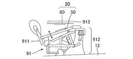
- FIG. 18 is a schematic diagram of a configuration in which the displacement sensor 20 is applied to the string striking mechanism 91 of the keyboard instrument 100.
- the string striking mechanism 91 is an action mechanism that strikes a string (not shown) in conjunction with the displacement of each key 12 of the keyboard 10.
- the string striking mechanism 91 includes a hammer 911 capable of striking a string by rotation and a transmission mechanism 912 (for example, a wipen, a jack, a repetition lever, etc.) that rotates the hammer 911 in conjunction with the displacement of the key 12. Is provided for each key 12.
- the detected portion 50 is installed on a hammer 911 (for example, a hammer shank).
- the signal generation unit 60 is installed on the support member 913.
- the displacement sensor 20 detects the displacement of the hammer 911.
- the support member 913 is a structure that supports, for example, the string striking mechanism 91.
- the detected portion 50 may be installed on a movable member other than the hammer 911 in the string striking mechanism 91.
- FIG. 19 is a schematic view of a configuration in which the displacement sensor 20 is applied to the pedal mechanism 92 of the keyboard instrument 100.
- the pedal mechanism 92 includes a pedal 921 operated by the user with his / her foot, a support member 922 that supports the pedal 921, and an elastic body 923 that urges the pedal 921 upward in the vertical direction.
- the detected portion 50 is installed on the bottom surface of the pedal 921.
- the signal generation unit 60 is installed on the support member 922 so as to face the detected unit 50.
- the displacement sensor 20 detects the displacement of the pedal 921.
- the musical instrument in which the pedal mechanism 92 is used is not limited to the keyboard instrument 100.
- a pedal mechanism 92 having the same configuration is used for any musical instrument such as a percussion instrument.
- the object of detection by the displacement sensor is comprehensively expressed as a movable member that is displaced according to the playing motion.
- the movable member includes a performance operator such as a key 12 or a pedal 921 directly operated by the user, and a structure such as a hammer 911 that is displaced in conjunction with an operation on the performance operator.
- the movable member in the present disclosure is not limited to the member that is displaced according to the playing motion. That is, the movable member is comprehensively expressed as a displaceable member regardless of the trigger for causing the displacement.
- the configuration in which the keyboard instrument 100 includes the sound source circuit 34 is illustrated, but in the configuration in which the keyboard instrument 100 includes a sounding mechanism such as a string striking mechanism 91, the sound source circuit 34 is omitted. You may.
- the detection system 15 is used to record the performance content of the keyboard instrument 100.
- the sound generation mechanism and the sound source circuit 34 are comprehensively expressed as a sound generation unit that generates sound according to the result of detection by the detection system 15.
- the present disclosure is also specified as a device (performance operation device) that controls a musical sound by outputting an operation signal according to a performance operation to the sound source circuit 34 or a sounding mechanism.
- the device not having the sound source circuit 34 or the sounding mechanism for example, the MIDI controller or the pedal mechanism 92 described above. It is included in the concept of instrument playing apparatus. That is, the performance operation device in the present disclosure is comprehensively expressed as a device operated by a performer (operator) for performance.
- the displacement sensor is installed on a movable member that is displaced according to an operation, and includes a detected portion including a first coil and a second coil facing the first coil. It includes a signal generation unit that generates a detection signal according to the relative position between the first coil and the second coil, and is orthogonal to the external dimensions of the first coil in the first direction and the first direction. It differs from the external dimensions of the first coil in the second direction in a plan view.
- the linearity when the detection signal changes according to the change in the relative position between the first coil of the detected portion and the second coil facing the detected portion is improved, so that the displacement of the movable member can be made highly accurate.
- the reflected detection signal can be generated. Therefore, the distance measurement distance can be extended.
- the "outer dimension" of the coil in a specific direction means the dimension (size) in the direction with respect to the contour line representing the outer shape of the coil, and is also paraphrased as the maximum value of the dimension of the coil in the direction.
- the detected portion includes a rectangular substrate on which the first coil is formed, the first direction is the long side direction of the substrate, and the second aspect is described.
- the direction is the short side direction of the substrate, and the external dimension of the first coil in the second direction is equal to or less than the dimension of the substrate in the short side direction.
- the external dimensions of the first coil in the first direction exceed the external dimensions of the first coil in the second direction.
- the displacement sensor is installed on a movable member that is displaced according to an operation, and a detected portion including the first coil and a second portion facing the first coil. It includes a coil and includes a signal generation unit that generates a detection signal according to a relative position between the first coil and the second coil, and the first coil mutually by supplying a current to the first coil.
- the second coil has a first portion and a second portion in which a magnetic field in opposite directions is generated, and the second coil has a third portion and a fourth portion in which magnetic currents in opposite directions are generated by supplying a current to the second coil.
- the first distance between the center of the first portion and the center of the second portion exceeds the second distance between the center of the third portion and the center of the fourth portion.
- the linearity when the detection signal changes according to the change in the relative position between the first coil of the detected portion and the second coil facing the detected portion is improved, so that the displacement of the movable member can be made highly accurate.
- the reflected detection signal can be generated. Further, since the leakage of the magnetic field generated by the second coil is reduced, the detection accuracy can be improved.
- the first distance is more than 100% of the second distance and 140% or less.
- the electronic musical instrument includes a displacement sensor according to any of the above-exemplified aspects and a sound control unit that generates an acoustic signal representing a sound according to the level of the detection signal. And.
- the displacement sensor includes a detected portion including a substrate on which a first coil is formed, and a second coil, which is installed on a movable member that is displaced according to an operation. It is provided with a signal generation unit that generates a detection signal according to the relative position between the first coil of the detected unit and the second coil facing the first coil, and both the detected unit and the signal generating unit are formed by a resonance circuit.
- the signal generation unit has a resistance element that lowers the Q value, and the detected unit does not have a resistance element that lowers the Q value.
- the displacement sensor includes a detected portion including a substrate on which a first coil is formed, and a second coil, which is installed on a movable member that is displaced according to an operation. It is provided with a signal generation unit that generates a detection signal according to the relative position between the first coil of the detected unit and the second coil facing the first coil, and the frequency of the detection signal of the signal generation unit is the resonance of the detected unit. The difference is lower than the frequency up to 2% (ie, between 98% and 100% of the resonance frequency).
- keyboard instrument electronic musical instrument
- 10 ... keyboard, 12 ... key, 15 ... detection system, 20 ... displacement sensor, 21 ... signal processing circuit, 22 ... supply circuit, 23 ... output circuit, 30 ... information processing device, 31 ... control device, 32 ... storage device, 33 ... A / D converter, 34 ... sound source circuit, 40 ... sound emitting device, 50 ... detected unit, 51 ... first coil, 52 ... capacitive element, 521 ... first part 522 ... 2nd part, 551 ... board, 523 ... 3rd part, 524 ... 4th part, 551, 552, 535 ... board, 60 ... signal generator, 61 ... second coil, 612 ... wiring pattern, 621 ...
Landscapes
- Physics & Mathematics (AREA)
- Engineering & Computer Science (AREA)
- Acoustics & Sound (AREA)
- Multimedia (AREA)
- General Physics & Mathematics (AREA)
- Electromagnetism (AREA)
- Measurement Of Length, Angles, Or The Like Using Electric Or Magnetic Means (AREA)
- Electrophonic Musical Instruments (AREA)
Abstract
This displacement sensor comprises a detectable unit installed on a movable member that is displaced in accordance with an operation, the detectable unit including a first coil, and a signal generation unit that includes a second coil opposed to the first coil and that generates a detection signal corresponding to a relative position of the first coil and the second coil. An external dimension of the first coil in a first direction and an external dimension of the first coil in a second direction orthogonal to the first direction are different in plan view.
Description
本開示は、変位センサーおよび電子楽器に関する。
This disclosure relates to displacement sensors and electronic musical instruments.
例えば鍵盤楽器における鍵等の可動部材の変位を検出するための各種の技術が従来から提案されている。特許文献1には、鍵盤楽器のフレームに設置されたコイルと、各鍵に設置された金属板とを利用して、各鍵の位置を検出する構成が開示されている。この構成において、押鍵により金属板が変位すると、コイルに流れる電流が変化する。コイルに流れる電流を検出することで、押鍵の変位を反映した検出信号が生成される。
For example, various techniques for detecting the displacement of movable members such as keys in a keyboard instrument have been conventionally proposed. Patent Document 1 discloses a configuration in which the position of each key is detected by using a coil installed in a frame of a keyboard instrument and a metal plate installed in each key. In this configuration, when the metal plate is displaced by pressing the key, the current flowing through the coil changes. By detecting the current flowing through the coil, a detection signal that reflects the displacement of the key press is generated.
しかしながら、特許文献1の技術において、可動部材の変位を高精度に反映した検出信号を生成することは困難である。このような事情を考慮して、本開示のひとつの態様は、可動部材の変位を高精度に反映した検出信号を生成することを目的とする。
However, in the technique of Patent Document 1, it is difficult to generate a detection signal that reflects the displacement of the movable member with high accuracy. In consideration of such circumstances, one aspect of the present disclosure is to generate a detection signal that reflects the displacement of the movable member with high accuracy.
上記目的を達成するために、本開示の一態様に係る変位センサーは、操作に応じて変位する可動部材に設置され、第1コイルを含む被検出部と、前記第1コイルに対向する第2コイルを含み、前記第1コイルと前記第2コイルとの相対位置に応じた検出信号を生成する信号生成部と、を具備し、第1方向における前記第1コイルの外形寸法と、前記第1方向に直交する第2方向における前記第1コイルの外形寸法とは平面視で異なる。
In order to achieve the above object, the displacement sensor according to one aspect of the present disclosure is installed on a movable member that is displaced according to an operation, and a detected portion including the first coil and a second coil facing the first coil. It includes a coil and includes a signal generation unit that generates a detection signal according to a relative position between the first coil and the second coil, and includes external dimensions of the first coil in the first direction and the first coil. It differs from the external dimensions of the first coil in the second direction orthogonal to the direction in a plan view.
本開示の別態様に係る変位センサーは、操作に応じて変位する可動部材に設置され、第1コイルを含む被検出部と、前記第1コイルに対向する第2コイルを含み、前記第1コイルと前記第2コイルとの相対位置に応じた検出信号を生成する信号生成部と、を具備し、前記第1コイルは、当該第1コイルに対する電流の供給により相互に逆向きの磁界が発生する第1部分および第2部分を有し、前記第2コイルは、当該第2コイルに対する電流の供給により相互に逆向きの磁界が発生する第3部分および第4部分を有し、前記第1部分の中心と前記第2部分の中心との第1距離は、前記第3部分の中心と前記第4部分の中心との第2距離を上回る。
The displacement sensor according to another aspect of the present disclosure is installed on a movable member that is displaced according to an operation, includes a detected portion including a first coil, and a second coil facing the first coil, and includes the first coil. A signal generation unit that generates a detection signal according to a relative position with the second coil is provided, and the first coil generates magnetic fields opposite to each other by supplying a current to the first coil. The second coil has a first portion and a second portion, and the second coil has a third portion and a fourth portion in which magnetic currents in opposite directions are generated by supplying an electric current to the second coil, and the first portion. The first distance between the center of the third portion and the center of the second portion exceeds the second distance between the center of the third portion and the center of the fourth portion.
A:実施形態
図1は、本開示のひとつの形態に係る変位センサーを適用した鍵盤楽器100の構成を例示するブロック図である。
鍵盤楽器100は、鍵盤10と検出システム15と情報処理装置30と放音装置40とを具備する電子楽器である。鍵盤10は、複数の白鍵と複数の黒鍵とを含む複数の鍵12で構成される。複数の鍵12の各々は、利用者による演奏動作に応じて変位する可動部材である。検出システム15は、鍵12の変位(位置)を検出する。情報処理装置30は、検出システム15による検出の結果に応じた音響信号Vを生成する。音響信号Vは、利用者が操作した鍵12に対応する音高の楽音を表す信号である。放音装置40は、音響信号Vが表す音響を放音する。例えばスピーカまたはヘッドホンが放音装置40として利用される。 A: Embodiment FIG. 1 is a block diagram illustrating a configuration of akeyboard instrument 100 to which a displacement sensor according to one embodiment of the present disclosure is applied.
Thekeyboard instrument 100 is an electronic musical instrument including a keyboard 10, a detection system 15, an information processing device 30, and a sound emitting device 40. The keyboard 10 is composed of a plurality of keys 12 including a plurality of white keys and a plurality of black keys. Each of the plurality of keys 12 is a movable member that is displaced according to the performance operation by the user. The detection system 15 detects the displacement (position) of the key 12. The information processing device 30 generates an acoustic signal V according to the result of detection by the detection system 15. The acoustic signal V is a signal representing a musical tone having a pitch corresponding to the key 12 operated by the user. The sound emitting device 40 emits the sound represented by the acoustic signal V. For example, a speaker or headphones are used as the sound emitting device 40.
図1は、本開示のひとつの形態に係る変位センサーを適用した鍵盤楽器100の構成を例示するブロック図である。
鍵盤楽器100は、鍵盤10と検出システム15と情報処理装置30と放音装置40とを具備する電子楽器である。鍵盤10は、複数の白鍵と複数の黒鍵とを含む複数の鍵12で構成される。複数の鍵12の各々は、利用者による演奏動作に応じて変位する可動部材である。検出システム15は、鍵12の変位(位置)を検出する。情報処理装置30は、検出システム15による検出の結果に応じた音響信号Vを生成する。音響信号Vは、利用者が操作した鍵12に対応する音高の楽音を表す信号である。放音装置40は、音響信号Vが表す音響を放音する。例えばスピーカまたはヘッドホンが放音装置40として利用される。 A: Embodiment FIG. 1 is a block diagram illustrating a configuration of a
The
図2は、鍵盤10のうち、1個の鍵12に着目して鍵盤楽器100の具体的な構成を例示するブロック図である。鍵盤10の各鍵12は、支点部13を支点として支持部材14に支持される。支持部材14は、鍵盤楽器100の各要素を支持する構造体である。各鍵12の端部121は、利用者による押鍵および離鍵により鉛直方向に変位する。検出システム15は、複数の鍵12の各々について、鉛直方向における端部121の位置Zに応じたレベルの検出信号Dを生成する。位置Zは、例えば、鍵12に荷重が作用しない解放状態における端部121の位置を基準とした当該端部121の変位量で表現される。
FIG. 2 is a block diagram illustrating a specific configuration of the keyboard instrument 100 by focusing on one key 12 of the keyboard 10. Each key 12 of the keyboard 10 is supported by the support member 14 with the fulcrum portion 13 as a fulcrum. The support member 14 is a structure that supports each element of the keyboard instrument 100. The end 121 of each key 12 is displaced in the vertical direction by the user pressing and releasing the key. The detection system 15 generates a detection signal D at a level corresponding to the position Z of the end portion 121 in the vertical direction for each of the plurality of keys 12. The position Z is represented by, for example, the amount of displacement of the end portion 121 with reference to the position of the end portion 121 in the released state in which no load acts on the key 12.
検出システム15は、鍵12毎に設けられる変位センサー20と各鍵12に共通の信号処理回路21とを具備する。変位センサー20は、各鍵12の位置を検出する位置センサーであり、被検出部50と信号生成部60とを含む。信号生成部60は、支持部材14に設置される。被検出部50は、鍵12に設置される。具体的には、被検出部50は、鍵12の底面(以下「設置面」という)122に設置される。被検出部50は第1コイル51を含む。信号生成部60は第2コイル61を含む。第1コイル51と第2コイル61とは、鉛直方向に相互に間隔をあけて対向する。信号生成部60と被検出部50との距離(第1コイル51と第2コイル61との距離)は、鍵12の端部121の位置Zが押鍵または離鍵により変化することに応じて変化する。信号処理回路21は、第1コイル51と第2コイル61との距離に応じたレベルの検出信号Dを生成する。
The detection system 15 includes a displacement sensor 20 provided for each key 12 and a signal processing circuit 21 common to each key 12. The displacement sensor 20 is a position sensor that detects the position of each key 12, and includes a detected unit 50 and a signal generating unit 60. The signal generation unit 60 is installed on the support member 14. The detected unit 50 is installed on the key 12. Specifically, the detected unit 50 is installed on the bottom surface (hereinafter referred to as “installation surface”) 122 of the key 12. The detected unit 50 includes the first coil 51. The signal generation unit 60 includes a second coil 61. The first coil 51 and the second coil 61 face each other in the vertical direction with a distance from each other. The distance between the signal generation unit 60 and the detected unit 50 (distance between the first coil 51 and the second coil 61) depends on the position Z of the end 121 of the key 12 being changed by pressing or releasing the key. Change. The signal processing circuit 21 generates a detection signal D at a level corresponding to the distance between the first coil 51 and the second coil 61.
情報処理装置30は、信号処理回路21から供給される検出信号Dを解析することで各鍵12の位置Zを解析する。情報処理装置30は、制御装置31と記憶装置32とA/D変換器33と音源回路34とを具備するコンピュータシステムで実現される。
The information processing device 30 analyzes the position Z of each key 12 by analyzing the detection signal D supplied from the signal processing circuit 21. The information processing device 30 is realized by a computer system including a control device 31, a storage device 32, an A / D converter 33, and a sound source circuit 34.
A/D変換器33は、信号処理回路21から供給される検出信号Dをアナログからデジタルに変換する。
制御装置31は、鍵盤楽器100の各要素を制御する単数または複数のプロセッサで構成される。例えば、制御装置31は、CPU(Central Processing Unit)、SPU(Sound Processing Unit)、DSP(Digital Signal Processor)、FPGA(Field Programmable Gate Array)、またはASIC(Application Specific Integrated Circuit)等の1種類以上のプロセッサで構成される。 The A /D converter 33 converts the detection signal D supplied from the signal processing circuit 21 from analog to digital.
Thecontrol device 31 is composed of a single or a plurality of processors that control each element of the keyboard instrument 100. For example, the control device 31 is one or more types such as a CPU (Central Processing Unit), an SPU (Sound Processing Unit), a DSP (Digital Signal Processor), an FPGA (Field Programmable Gate Array), or an ASIC (Application Specific Integrated Circuit). It consists of a processor.
制御装置31は、鍵盤楽器100の各要素を制御する単数または複数のプロセッサで構成される。例えば、制御装置31は、CPU(Central Processing Unit)、SPU(Sound Processing Unit)、DSP(Digital Signal Processor)、FPGA(Field Programmable Gate Array)、またはASIC(Application Specific Integrated Circuit)等の1種類以上のプロセッサで構成される。 The A /
The
制御装置31は、A/D変換器33による変換後の検出信号Dを解析することで各鍵12の位置Zを解析する。また、制御装置31は、各鍵12の位置Zに応じた楽音の発音を音源回路34に対して指示する。音源回路34は、制御装置31から指示された楽音を表す音響信号Vを生成する。すなわち、音源回路34は、検出信号Dの電圧レベルδに応じて鍵が所定の位置に達したことを検出して音響信号Vの生成を開始する。そして、例えば電圧レベルδの速度変化に応じて音響信号Vの音量が制御される。音響信号Vが音源回路34から放音装置40に供給されることで、利用者による演奏動作に応じた楽音が放音装置40から放音される。具体的には、利用者による各鍵12の押鍵により楽音が放音され、当該鍵12の離鍵により楽音が停止される。
The control device 31 analyzes the position Z of each key 12 by analyzing the detection signal D after conversion by the A / D converter 33. Further, the control device 31 instructs the sound source circuit 34 to pronounce a musical tone according to the position Z of each key 12. The sound source circuit 34 generates an acoustic signal V representing a musical tone instructed by the control device 31. That is, the sound source circuit 34 detects that the key has reached a predetermined position according to the voltage level δ of the detection signal D, and starts generating the acoustic signal V. Then, for example, the volume of the acoustic signal V is controlled according to the speed change of the voltage level δ. By supplying the acoustic signal V from the sound source circuit 34 to the sound emitting device 40, a musical sound corresponding to the performance operation by the user is emitted from the sound emitting device 40. Specifically, the musical sound is emitted when the user presses each key 12, and the musical sound is stopped when the key 12 is released.
記憶装置32は、制御装置31が実行するプログラムと制御装置31が使用するデータとを記憶する単数または複数のメモリである。記憶装置32は、例えば磁気記録媒体または半導体記録媒体等の公知の記録媒体で構成される。なお、複数種の記録媒体の組合せにより記憶装置32を構成してもよい。また、鍵盤楽器100に着脱可能な可搬型の記録媒体、または、鍵盤楽器100が通信可能な外部記録媒体(例えばオンラインストレージ)を、記憶装置32として利用してもよい。なお、記憶装置32に記憶されたプログラムを実行することで制御装置31が音源回路34の機能を実現してもよい。音源回路34、または、音源回路34の機能を実現する制御装置31は、検出信号Dの電圧レベルδに応じた音響信号Vを生成する音制御部として機能する。
The storage device 32 is a single or a plurality of memories for storing a program executed by the control device 31 and data used by the control device 31. The storage device 32 is composed of a known recording medium such as a magnetic recording medium or a semiconductor recording medium. The storage device 32 may be configured by combining a plurality of types of recording media. Further, a portable recording medium that can be attached to and detached from the keyboard instrument 100, or an external recording medium (for example, online storage) that the keyboard instrument 100 can communicate with may be used as the storage device 32. The control device 31 may realize the function of the sound source circuit 34 by executing the program stored in the storage device 32. The sound source circuit 34 or the control device 31 that realizes the function of the sound source circuit 34 functions as a sound control unit that generates an acoustic signal V corresponding to the voltage level δ of the detection signal D.
図3は、変位センサー20を構成する被検出部50と信号生成部60とにおける電気的な構成を例示する回路図である。
信号生成部60は、入力端子T1と出力端子T2と第2コイル61と容量素子62と容量素子63と抵抗素子64とを含む。信号生成部60では、共振回路が第2コイル61と容量素子62と容量素子63と抵抗素子64とによって構成される。入力端子T1は抵抗素子64の一端に接続され、抵抗素子64の他端は容量素子62の一端および第2コイル61の一端に接続される。第2コイル61の他端は出力端子T2および容量素子63の一端に接続される。容量素子62の他端および容量素子63の他端は電圧ゼロの基準である電位Gndに接地される。 FIG. 3 is a circuit diagram illustrating an electrical configuration of the detectedunit 50 and the signal generating unit 60 constituting the displacement sensor 20.
Thesignal generation unit 60 includes an input terminal T1, an output terminal T2, a second coil 61, a capacitance element 62, a capacitance element 63, and a resistance element 64. In the signal generation unit 60, the resonance circuit is composed of the second coil 61, the capacitance element 62, the capacitance element 63, and the resistance element 64. The input terminal T1 is connected to one end of the resistance element 64, and the other end of the resistance element 64 is connected to one end of the capacitance element 62 and one end of the second coil 61. The other end of the second coil 61 is connected to one end of the output terminal T2 and the capacitance element 63. The other end of the capacitance element 62 and the other end of the capacitance element 63 are grounded to the potential Gnd, which is a reference for zero voltage.
信号生成部60は、入力端子T1と出力端子T2と第2コイル61と容量素子62と容量素子63と抵抗素子64とを含む。信号生成部60では、共振回路が第2コイル61と容量素子62と容量素子63と抵抗素子64とによって構成される。入力端子T1は抵抗素子64の一端に接続され、抵抗素子64の他端は容量素子62の一端および第2コイル61の一端に接続される。第2コイル61の他端は出力端子T2および容量素子63の一端に接続される。容量素子62の他端および容量素子63の他端は電圧ゼロの基準である電位Gndに接地される。 FIG. 3 is a circuit diagram illustrating an electrical configuration of the detected
The
一方、被検出部50は、第1コイル51と容量素子52とを含む。第1コイル51の一端と容量素子52の一端とが相互に接続され、第1コイル51の他端と容量素子52の他端とが相互に接続される。第1コイル51と容量素子52とによって共振回路が構成される。信号生成部60の共振周波数は、例えば被検出部50の共振周波数との関係に応じて設定される。設定される信号生成部60の共振周波数は、例えば、被検出部50の共振周波数とほぼ同等の周波数、または、被検出部50の共振周波数に所定の定数を乗算した周波数に設定される。
On the other hand, the detected unit 50 includes the first coil 51 and the capacitive element 52. One end of the first coil 51 and one end of the capacitance element 52 are connected to each other, and the other end of the first coil 51 and the other end of the capacitance element 52 are connected to each other. A resonance circuit is formed by the first coil 51 and the capacitive element 52. The resonance frequency of the signal generation unit 60 is set according to the relationship with the resonance frequency of the detected unit 50, for example. The set resonance frequency of the signal generation unit 60 is set to, for example, a frequency substantially equal to the resonance frequency of the detected unit 50, or a frequency obtained by multiplying the resonance frequency of the detected unit 50 by a predetermined constant.
信号生成部60の入力端子T1には基準信号Rが供給される。基準信号Rは、周期的にレベルが変動する電圧信号である。例えば正弦波等の任意の波形の周期信号が基準信号Rとして利用される。基準信号Rの周波数は、被検出部50の共振周波数との関係等に応じて設定される。例えば、基準信号Rの周波数は、信号生成部60および被検出部50の共振周波数とほぼ同等である。
The reference signal R is supplied to the input terminal T1 of the signal generation unit 60. The reference signal R is a voltage signal whose level fluctuates periodically. For example, a periodic signal having an arbitrary waveform such as a sine wave is used as the reference signal R. The frequency of the reference signal R is set according to the relationship with the resonance frequency of the detected unit 50 and the like. For example, the frequency of the reference signal R is substantially the same as the resonance frequency of the signal generation unit 60 and the detected unit 50.
基準信号Rに応じた電流が第2コイル61に供給されることで、当該第2コイル61に磁界が発生する。第2コイル61に発生した磁界による電磁誘導で第1コイル51には誘導電流が発生する。したがって、第2コイル61の磁界の変化を相殺する方向の磁界が第1コイル51に発生する。第1コイル51に発生する磁界は、第1コイル51と第2コイル61との距離drに応じて変化する。このため、第1コイル51と第2コイル61との距離drに応じた電圧レベルδ(ピークトゥーピーク値)の検出信号dが信号生成部60の出力端子T2から出力される。検出信号dは、基準信号Rと同じ周期でレベルが変動する周期信号である。
A magnetic field is generated in the second coil 61 by supplying a current corresponding to the reference signal R to the second coil 61. An induced current is generated in the first coil 51 by electromagnetic induction due to the magnetic field generated in the second coil 61. Therefore, a magnetic field in a direction that cancels the change in the magnetic field of the second coil 61 is generated in the first coil 51. The magnetic field generated in the first coil 51 changes according to the distance dr between the first coil 51 and the second coil 61. Therefore, the detection signal d of the voltage level δ (peak-to-peak value) corresponding to the distance dr between the first coil 51 and the second coil 61 is output from the output terminal T2 of the signal generation unit 60. The detection signal d is a periodic signal whose level fluctuates in the same period as the reference signal R.
図4は、信号処理回路21の具体的な構成を例示するブロック図である。信号処理回路21は、供給回路22と出力回路23とを具備する。供給回路22は、複数の信号生成部60の入力端子T1の各々に基準信号Rを供給する。供給回路22は、各信号生成部60に対して基準信号Rを時分割で供給する。具体的には、供給回路22は、複数の信号生成部60の各々を順次に選択し、選択状態の信号生成部60に対して基準信号Rを供給するデマルチプレクサである。すなわち、複数の信号生成部60の各々に対して時分割で基準信号Rが供給される。なお、基準信号Rの周期は、供給回路22が1個の信号生成部60を選択する期間の時間長よりも十分に短い。
FIG. 4 is a block diagram illustrating a specific configuration of the signal processing circuit 21. The signal processing circuit 21 includes a supply circuit 22 and an output circuit 23. The supply circuit 22 supplies the reference signal R to each of the input terminals T1 of the plurality of signal generation units 60. The supply circuit 22 supplies the reference signal R to each signal generation unit 60 in a time-division manner. Specifically, the supply circuit 22 is a demultiplexer that sequentially selects each of the plurality of signal generation units 60 and supplies the reference signal R to the selected signal generation unit 60. That is, the reference signal R is supplied to each of the plurality of signal generation units 60 in a time-division manner. The period of the reference signal R is sufficiently shorter than the time length of the period during which the supply circuit 22 selects one signal generation unit 60.
出力回路23は、複数の信号生成部60の各々から順次に出力される検出信号dを時間軸上に配列することで検出信号Dを生成する。すなわち、検出信号Dは、各鍵12における第1コイル51と第2コイル61との距離drに応じた電圧レベルδの信号を時分割で示す信号である。前述の通り第1コイル51と第2コイル61との距離drは各鍵12の位置Zに相関するから、検出信号Dは、複数の鍵12の各々の位置Zに応じた信号となる。すなわち、1個の鍵12でみれば、検出信号dは、第1コイル51と、当該第1コイル51に対向する第2コイル61との相対位置に応じた信号と表現される。出力回路23が生成した検出信号Dは、情報処理装置30に供給される。
The output circuit 23 generates the detection signal D by arranging the detection signals d sequentially output from each of the plurality of signal generation units 60 on the time axis. That is, the detection signal D is a signal indicating the signal of the voltage level δ corresponding to the distance dr between the first coil 51 and the second coil 61 in each key 12 in a time division manner. As described above, since the distance dr between the first coil 51 and the second coil 61 correlates with the position Z of each key 12, the detection signal D is a signal corresponding to each position Z of the plurality of keys 12. That is, when viewed with one key 12, the detection signal d is expressed as a signal corresponding to the relative position between the first coil 51 and the second coil 61 facing the first coil 51. The detection signal D generated by the output circuit 23 is supplied to the information processing device 30.
続いて、被検出部50と信号生成部60の構成について説明する。
図5は、当該被検出部50の具体的な構成を示す平面図であって、被検出部50を信号生成部60側からみた図である。図6は、図5におけるA-a線の断面図である。 Subsequently, the configuration of the detectedunit 50 and the signal generation unit 60 will be described.
FIG. 5 is a plan view showing a specific configuration of the detectedunit 50, and is a view of the detected unit 50 as viewed from the signal generation unit 60 side. FIG. 6 is a cross-sectional view taken along the line Aa in FIG.
図5は、当該被検出部50の具体的な構成を示す平面図であって、被検出部50を信号生成部60側からみた図である。図6は、図5におけるA-a線の断面図である。 Subsequently, the configuration of the detected
FIG. 5 is a plan view showing a specific configuration of the detected
被検出部50は、基板551と、当該基板551の表面F1および表面F2に設けられた配線パターンとを含む。基板551は、一例として、絶縁性を有する長方形状の板状部材である。被検出部50の表面F1は、鍵12の設置面122に取り付けられる面である。被検出部50の配線パターンは、基板551の表面F1およびF2に設けられた銅箔等の導電層のパターニングにより形成される。
なお、図5において上下方向が複数の鍵12が配列する方向であり、左右方向が1個の鍵12における長手方向である。鍵12の設置面122に取り付けられる被検出部50における幅Bwは、1個の鍵12の幅Kw以下である。 The detectedunit 50 includes a substrate 551 and wiring patterns provided on the surfaces F1 and F2 of the substrate 551. As an example, the substrate 551 is a rectangular plate-shaped member having an insulating property. The surface F1 of the detected portion 50 is a surface attached to the installation surface 122 of the key 12. The wiring pattern of the detected portion 50 is formed by patterning a conductive layer such as a copper foil provided on the surfaces F1 and F2 of the substrate 551.
In FIG. 5, the vertical direction is the direction in which a plurality ofkeys 12 are arranged, and the horizontal direction is the longitudinal direction of one key 12. The width Bw of the detected portion 50 attached to the installation surface 122 of the key 12 is equal to or less than the width Kw of one key 12.
なお、図5において上下方向が複数の鍵12が配列する方向であり、左右方向が1個の鍵12における長手方向である。鍵12の設置面122に取り付けられる被検出部50における幅Bwは、1個の鍵12の幅Kw以下である。 The detected
In FIG. 5, the vertical direction is the direction in which a plurality of
また、表面F2は、表面F1とは反対側の表面である。このため、表面F2は信号生成部60に対向する。被検出部50の第1コイル51は、第1部分521と第2部分522とによって構成される。第1部分521および第2部分522は、基板551の表面F2に形成された配線パターンの一部である。第1部分521は、渦巻き状に形成された部分である。第2部分522は、第1部分521と略同じ形状に形成された部分である。すなわち、第2部分522は、第1部分521の巻方向と同方向の渦巻き状に形成される。
第1部分521の渦巻き中心はビアC1であり、第2部分522の渦巻き中心はビアC2である。ビアC1およびビアC2は表面F1の配線パターン515によって導通する。 Further, the surface F2 is a surface opposite to the surface F1. Therefore, the surface F2 faces thesignal generation unit 60. The first coil 51 of the detected portion 50 is composed of a first portion 521 and a second portion 522. The first portion 521 and the second portion 522 are a part of the wiring pattern formed on the surface F2 of the substrate 551. The first portion 521 is a portion formed in a spiral shape. The second portion 522 is a portion formed in substantially the same shape as the first portion 521. That is, the second portion 522 is formed in a spiral shape in the same direction as the winding direction of the first portion 521.
The spiral center of thefirst portion 521 is the via C1, and the spiral center of the second portion 522 is the via C2. The via C1 and the via C2 are conducted by the wiring pattern 515 of the surface F1.
第1部分521の渦巻き中心はビアC1であり、第2部分522の渦巻き中心はビアC2である。ビアC1およびビアC2は表面F1の配線パターン515によって導通する。 Further, the surface F2 is a surface opposite to the surface F1. Therefore, the surface F2 faces the
The spiral center of the
本実施形態において、第1部分521の渦巻きでは、ビアC1から延在する直線がほぼ90度ずつ屈曲して外側に向かって拡がる。第1部分521の外形は長方形である。同様に、第2部分522の渦巻きはビアC2から延在する直線がほぼ90度ずつ屈曲して外側に向かって拡がる。第2部分522の外形は長方形である。
第1部分521および第2部分522の外形は長方形状である。図5においては、第1部分521および第2部分522の各々について、基板551の長辺方向における外形寸法COLと、基板551の短辺方向における外形寸法COWとが図示されている。外形寸法COWは、基板551の短辺方向における第1コイル51の寸法(サイズ)に相当する。第1部分521および第2部分522の各々の外形寸法COWは、短辺方向における基板551の寸法Bw以下である。基板551の長辺方向は、第1部分521および第2部分522の並び方向、すなわち鍵12の長手方向に一致する。また、基板551の短辺方向は、第1部分521および第2部分522の並び方向に直交する方向、すなわち鍵12の幅方向に一致する。 In the present embodiment, in the spiral of thefirst portion 521, the straight line extending from the via C1 is bent by about 90 degrees and spreads outward. The outer shape of the first portion 521 is rectangular. Similarly, in the spiral of the second portion 522, the straight line extending from the via C2 is bent by about 90 degrees and spreads outward. The outer shape of the second portion 522 is rectangular.
The outer shape of thefirst portion 521 and the second portion 522 is rectangular. In FIG. 5, for each of the first portion 521 and the second portion 522, the external dimension COL in the long side direction of the substrate 551 and the external dimension COW in the short side direction of the substrate 551 are shown. The external dimension COW corresponds to the dimension (size) of the first coil 51 in the short side direction of the substrate 551. The external dimension COW of each of the first portion 521 and the second portion 522 is equal to or less than the dimension Bw of the substrate 551 in the short side direction. The long side direction of the substrate 551 coincides with the arrangement direction of the first portion 521 and the second portion 522, that is, the longitudinal direction of the key 12. Further, the short side direction of the substrate 551 coincides with the direction orthogonal to the arrangement direction of the first portion 521 and the second portion 522, that is, the width direction of the key 12.
第1部分521および第2部分522の外形は長方形状である。図5においては、第1部分521および第2部分522の各々について、基板551の長辺方向における外形寸法COLと、基板551の短辺方向における外形寸法COWとが図示されている。外形寸法COWは、基板551の短辺方向における第1コイル51の寸法(サイズ)に相当する。第1部分521および第2部分522の各々の外形寸法COWは、短辺方向における基板551の寸法Bw以下である。基板551の長辺方向は、第1部分521および第2部分522の並び方向、すなわち鍵12の長手方向に一致する。また、基板551の短辺方向は、第1部分521および第2部分522の並び方向に直交する方向、すなわち鍵12の幅方向に一致する。 In the present embodiment, in the spiral of the
The outer shape of the
なお、ビアC1は第1部分521の中心に位置する。この中心は、第1部分521の外形である長方形の対角線が交差する地点である。同様に、ビアC2は第2部分522の中心に位置する。この中心は、第2部分522の外形である長方形の対角線が交差する地点である。
また、第1部分521の中心(ビアC1)と第2部分522の中心(ビアC2)との距離をL1とする。なお、距離L1は第1距離の一例である。 The via C1 is located at the center of thefirst portion 521. This center is the point where the diagonal lines of the rectangle, which is the outer shape of the first portion 521, intersect. Similarly, the via C2 is located in the center of the second portion 522. This center is the point where the diagonal lines of the rectangle, which is the outer shape of the second part 522, intersect.
Further, the distance between the center of the first portion 521 (via C1) and the center of the second portion 522 (via C2) is defined as L1. The distance L1 is an example of the first distance.
また、第1部分521の中心(ビアC1)と第2部分522の中心(ビアC2)との距離をL1とする。なお、距離L1は第1距離の一例である。 The via C1 is located at the center of the
Further, the distance between the center of the first portion 521 (via C1) and the center of the second portion 522 (via C2) is defined as L1. The distance L1 is an example of the first distance.
第1部分521のビアC1を一端とした場合の当該第1部分521の他端と、第2部分522のビアC2を一端とした場合の当該第2部分522の他端との間に、容量素子52が実装される。したがって、被検出部50の等価回路は、図3に示したように第1コイル51の両端に容量素子52が接続された構成となる。
なお、本実施形態では、第1部分521および第2部分522を同一寸法、同一形状としたが、これに限定されるものではない。例えば、第1部分521および第2部分522の間で形状または寸法が相違してもよい。また、第1部分521と第2部分522との一方または双方の平面形状を、図5の縦方向が長手方向であり図5の横方向が短手方向である矩形状としてもよい。また、第1コイル51の平面形状は、第1部分521と第2部分522とを含む形状に限定されない。すなわち、第1コイル51は、ひとつの巻回部で構成されてもよい。 A capacitance is provided between the other end of thefirst portion 521 when the via C1 of the first portion 521 is used as one end and the other end of the second portion 522 when the via C2 of the second portion 522 is used as one end. The element 52 is mounted. Therefore, the equivalent circuit of the detected unit 50 has a configuration in which the capacitance elements 52 are connected to both ends of the first coil 51 as shown in FIG.
In the present embodiment, thefirst portion 521 and the second portion 522 have the same dimensions and the same shape, but the present invention is not limited to this. For example, the shape or dimensions may differ between the first portion 521 and the second portion 522. Further, the planar shape of one or both of the first portion 521 and the second portion 522 may be a rectangular shape in which the vertical direction in FIG. 5 is the longitudinal direction and the horizontal direction in FIG. 5 is the lateral direction. Further, the planar shape of the first coil 51 is not limited to the shape including the first portion 521 and the second portion 522. That is, the first coil 51 may be composed of one winding portion.
なお、本実施形態では、第1部分521および第2部分522を同一寸法、同一形状としたが、これに限定されるものではない。例えば、第1部分521および第2部分522の間で形状または寸法が相違してもよい。また、第1部分521と第2部分522との一方または双方の平面形状を、図5の縦方向が長手方向であり図5の横方向が短手方向である矩形状としてもよい。また、第1コイル51の平面形状は、第1部分521と第2部分522とを含む形状に限定されない。すなわち、第1コイル51は、ひとつの巻回部で構成されてもよい。 A capacitance is provided between the other end of the
In the present embodiment, the
図8は、信号生成部60の具体的な構成を示す平面図であって、信号生成部60を被検出部50側からみた図である。また、図9は、図8におけるB-b線の断面図である。
FIG. 8 is a plan view showing a specific configuration of the signal generation unit 60, and is a view of the signal generation unit 60 as viewed from the detected unit 50 side. Further, FIG. 9 is a cross-sectional view taken along the line BB in FIG.
信号生成部60は、基板651と、当該基板651の表面F3および表面F4に設けられた配線パターンとを含む。基板651は、絶縁性を有する板状部材である。信号生成部60の表面F4は、支持部材14に対向する。表面F3は、表面F4とは反対側の表面であり、被検出部50に対向する。配線パターンは、基板651の表面F3およびF4に設けられた銅箔等の導電層のパターニングにより形成される。
The signal generation unit 60 includes a substrate 651 and wiring patterns provided on the surfaces F3 and F4 of the substrate 651. The substrate 651 is a plate-shaped member having an insulating property. The surface F4 of the signal generation unit 60 faces the support member 14. The surface F3 is a surface opposite to the surface F4 and faces the detected portion 50. The wiring pattern is formed by patterning a conductive layer such as a copper foil provided on the surfaces F3 and F4 of the substrate 651.
図8における上下方向は、複数の鍵12(図8においては図示略)が配列する方向である。図8における左右方向は、1個の鍵12における長手方向である。鍵12の長手方向とは、当該鍵12の先端側(演奏者側)から鍵12の根元側に向かう方向である。
The vertical direction in FIG. 8 is the direction in which a plurality of keys 12 (not shown in FIG. 8) are arranged. The left-right direction in FIG. 8 is the longitudinal direction of one key 12. The longitudinal direction of the key 12 is a direction from the tip end side (performer side) of the key 12 toward the root side of the key 12.
信号生成部60の第2コイル61は、第3部分621と第4部分622とによって構成される。第3部分621および第4部分622は、表面F3に形成された配線パターンの一部である。第3部分621は、略正方形状で渦巻き状に形成された部分である。第4部分622は、第3部分621と略同じ形状に形成された部分である。すなわち、第4部分622は、第3部分621の巻方向と同方向の渦巻き状に形成される。
第3部分621の渦巻き中心はビアC11であり、第4部分622の渦巻き中心はビアC12である。ビアC11およびビアC12が表面F4の配線パターン612によって導通する。
なお、本実施形態では、第3部分621および第4部分622を同一寸法、同一形状としたが、これに限定されるものではない。例えば、第3部分621および第4部分622の間で寸法が相違してもよい。また、第3部分621および第4部分622を互いに異なる形状としてもよい。また、第2コイル61の平面形状は、第3部分621と第4部分622とを含む形状に限定されない。すなわち、第2コイル61は、ひとつの巻回部で構成されてもよい。 Thesecond coil 61 of the signal generation unit 60 is composed of a third portion 621 and a fourth portion 622. The third portion 621 and the fourth portion 622 are a part of the wiring pattern formed on the surface F3. The third portion 621 is a portion formed in a substantially square shape and in a spiral shape. The fourth portion 622 is a portion formed in substantially the same shape as the third portion 621. That is, the fourth portion 622 is formed in a spiral shape in the same direction as the winding direction of the third portion 621.
The spiral center of thethird portion 621 is the via C11, and the spiral center of the fourth portion 622 is the via C12. The via C11 and the via C12 are conducted by the wiring pattern 612 of the surface F4.
In the present embodiment, thethird portion 621 and the fourth portion 622 have the same dimensions and the same shape, but the present invention is not limited to this. For example, the dimensions may differ between the third portion 621 and the fourth portion 622. Further, the third portion 621 and the fourth portion 622 may have different shapes from each other. Further, the planar shape of the second coil 61 is not limited to the shape including the third portion 621 and the fourth portion 622. That is, the second coil 61 may be composed of one winding portion.
第3部分621の渦巻き中心はビアC11であり、第4部分622の渦巻き中心はビアC12である。ビアC11およびビアC12が表面F4の配線パターン612によって導通する。
なお、本実施形態では、第3部分621および第4部分622を同一寸法、同一形状としたが、これに限定されるものではない。例えば、第3部分621および第4部分622の間で寸法が相違してもよい。また、第3部分621および第4部分622を互いに異なる形状としてもよい。また、第2コイル61の平面形状は、第3部分621と第4部分622とを含む形状に限定されない。すなわち、第2コイル61は、ひとつの巻回部で構成されてもよい。 The
The spiral center of the
In the present embodiment, the
本実施形態において、第3部分621の外形は略正方形である。同様に、第4部分622の外形は略正方形である。
第3部分621および第4部分622の外形である正方形の一辺の方向は、鍵12の長手方向に一致し、当該一辺に直交する方向は、鍵12の幅方向に一致する。当該正方形の1辺の寸法(外形寸法)をB2とする。 In the present embodiment, the outer shape of thethird portion 621 is substantially square. Similarly, the outer shape of the fourth portion 622 is substantially square.
The direction of one side of the square, which is the outer shape of thethird portion 621 and the fourth portion 622, coincides with the longitudinal direction of the key 12, and the direction orthogonal to the one side coincides with the width direction of the key 12. Let B2 be the dimension (external dimension) of one side of the square.
第3部分621および第4部分622の外形である正方形の一辺の方向は、鍵12の長手方向に一致し、当該一辺に直交する方向は、鍵12の幅方向に一致する。当該正方形の1辺の寸法(外形寸法)をB2とする。 In the present embodiment, the outer shape of the
The direction of one side of the square, which is the outer shape of the
なお、ビアC11は第3部分621の中心に位置し、ビアC12は第4部分622の中心に位置する。ここでいう中心は、平面視におけるコイルの中心であり、正方形または長方形であれば対角線が交差する地点であり、円形であれば外円の中心である。
また、第3部分621の中心(本実施形態ではビアC11)と第4部分622の中心(本実施形態ではビアC12)との距離をL2とする。なお、距離L2は第2距離の一例である。 The via C11 is located at the center of thethird portion 621, and the via C12 is located at the center of the fourth portion 622. The center here is the center of the coil in a plan view, is the point where the diagonal lines intersect in the case of a square or rectangle, and is the center of the outer circle in the case of a circle.
Further, the distance between the center of the third portion 621 (via C11 in the present embodiment) and the center of the fourth portion 622 (via C12 in the present embodiment) is L2. The distance L2 is an example of the second distance.
また、第3部分621の中心(本実施形態ではビアC11)と第4部分622の中心(本実施形態ではビアC12)との距離をL2とする。なお、距離L2は第2距離の一例である。 The via C11 is located at the center of the
Further, the distance between the center of the third portion 621 (via C11 in the present embodiment) and the center of the fourth portion 622 (via C12 in the present embodiment) is L2. The distance L2 is an example of the second distance.
表面F3の配線パターンのうち、第2コイル61以外の部分は、容量素子62および容量素子63、抵抗素子64、入力端子T1および出力端子T2を接続するための配線である。前述の通り、入力端子T1には、基準信号Rが供給回路22から供給され、出力端子T2からは、第1コイル51と第2コイル61との距離drに応じた電圧レベルδの検出信号dが出力される。
被検出部50と信号生成部60の以上の構成において、第1部分521と第3部分621とが対向し、第2部分522と第4部分622とが対向する。そして、一例であるが、寸法関係として、COW=B2×70%、COL=B2となっている。 The portion of the wiring pattern of the surface F3 other than thesecond coil 61 is wiring for connecting the capacitance element 62, the capacitance element 63, the resistance element 64, the input terminal T1 and the output terminal T2. As described above, the reference signal R is supplied to the input terminal T1 from the supply circuit 22, and the detection signal d of the voltage level δ corresponding to the distance dr between the first coil 51 and the second coil 61 is supplied from the output terminal T2. Is output.
In the above configuration of the detectedunit 50 and the signal generation unit 60, the first portion 521 and the third portion 621 face each other, and the second portion 522 and the fourth portion 622 face each other. And, as an example, the dimensional relationship is COW = B2 × 70% and COL = B2.
被検出部50と信号生成部60の以上の構成において、第1部分521と第3部分621とが対向し、第2部分522と第4部分622とが対向する。そして、一例であるが、寸法関係として、COW=B2×70%、COL=B2となっている。 The portion of the wiring pattern of the surface F3 other than the
In the above configuration of the detected
次に、被検出部50と信号生成部60における回路の動作について説明する。図7は、被検出部50により発生する磁界方向の一例を示す図である。図10は、信号生成部60により発生する磁界方向の一例を示す図である。
信号生成部60に対する基準信号Rの供給により、例えば図8においてビアC11を起点に反時計回りの電流が第3部分621に流れる場合、ビアC12に向かって時計回りの電流が第4部分622に流れる。このため、磁界は、第3部分621においては、図8の紙面手前方向および図10の上方向に発生し、第4部分622においては、図8の紙面奧方向および図10の下方向に発生する。 Next, the operation of the circuit in the detectedunit 50 and the signal generation unit 60 will be described. FIG. 7 is a diagram showing an example of the magnetic field direction generated by the detected unit 50. FIG. 10 is a diagram showing an example of the magnetic field direction generated by the signal generation unit 60.
By supplying the reference signal R to thesignal generation unit 60, for example, when a counterclockwise current flows from the via C11 to the third portion 621 in FIG. 8, the clockwise current flows to the fourth portion 622 toward the via C12. It flows. Therefore, in the third portion 621, the magnetic field is generated in the front direction of the paper surface of FIG. 8 and the upward direction of FIG. 10, and in the fourth portion 622, it is generated in the paper surface direction of FIG. 8 and the downward direction of FIG. do.
信号生成部60に対する基準信号Rの供給により、例えば図8においてビアC11を起点に反時計回りの電流が第3部分621に流れる場合、ビアC12に向かって時計回りの電流が第4部分622に流れる。このため、磁界は、第3部分621においては、図8の紙面手前方向および図10の上方向に発生し、第4部分622においては、図8の紙面奧方向および図10の下方向に発生する。 Next, the operation of the circuit in the detected
By supplying the reference signal R to the
すなわち、図10に例示される通り、第3部分621と第4部分622とでは互いに逆方向の磁界が発生する。前述の通り、鍵盤10において複数の鍵12が図10の紙面垂直方向に配列する。したがって、第3部分621と第4部分622とで逆方向の磁界が発生することで、相互に隣り合う各鍵12に対向する信号生成部60で発生する磁界の拡散が低減される。磁界の拡散が低減される結果、複数の鍵12の各々の位置Zを高精度に反映した検出信号Dが生成される。
That is, as illustrated in FIG. 10, magnetic fields in opposite directions are generated in the third portion 621 and the fourth portion 622. As described above, on the keyboard 10, a plurality of keys 12 are arranged in the direction perpendicular to the paper surface of FIG. Therefore, the magnetic fields generated in the opposite directions in the third portion 621 and the fourth portion 622 reduce the diffusion of the magnetic fields generated in the signal generation unit 60 facing each key 12 adjacent to each other. As a result of reducing the diffusion of the magnetic field, a detection signal D that accurately reflects each position Z of the plurality of keys 12 is generated.
なお、図10においては、図8において第3部分621に反時計回りの電流が流れ、第4部分622に時計回りの電流が流れる場合が例示されている。第3部分621に時計回りの電流が流れ、第4部分622に反時計回りの電流が流れる場合にも同様に、磁界の方向は逆向きとなる。
Note that, in FIG. 10, a case where a counterclockwise current flows through the third portion 621 and a clockwise current flows through the fourth portion 622 is illustrated in FIG. Similarly, when a clockwise current flows through the third portion 621 and a counterclockwise current flows through the fourth portion 622, the direction of the magnetic field is opposite.
信号生成部60における第2コイル61の第3部分621および第4部分622は、表面F4の導電層のパターニングにより形成される。このため、例えば第2コイル61を導電線の巻回により形成する構成と比較して、第2コイル61の製造および取扱が容易であるという利点がある。
The third portion 621 and the fourth portion 622 of the second coil 61 in the signal generation unit 60 are formed by patterning the conductive layer on the surface F4. Therefore, for example, as compared with a configuration in which the second coil 61 is formed by winding a conductive wire, there is an advantage that the second coil 61 can be easily manufactured and handled.
このように、信号生成部60に基準信号Rが供給された状態において、第1コイル51が第2コイル61から離れる方向に移動する場合、第1コイル51には、第2コイル61により生成される磁界が減るのを阻止する方向の磁界(すなわち、第2コイル61の発生磁界と同方向の磁界が)発生する。したがって、この場合、第1コイル51には、第2コイル61により生成される磁界と同方向の磁界に応じた電流が誘起される。
例えば、図10に示される方向の磁界が信号生成部60の第2コイル61によって発生した状態で、被検出部50の第1コイル51が第2コイル61に離れる方向に移動する場合、第1コイル51には、第2コイル61により生成される磁界と同方向の磁界が発生する。
このため、図5において、第1コイル51の第1部分521には電流が時計回りで流れ、第2部分522には電流が反時計回りで流れる。
また、図10に示される方向の磁界が信号生成部60の第2コイル61によって発生した状態で、被検出部50の第1コイル51が第2コイル61に接近する方向に移動する場合、第1コイル51には、第2コイル61により生成される磁界とは逆方向の磁界が発生する。
このため、図5において、第1コイル51の第1部分521には電流が反時計回りで流れ、第2部分522には電流が時計回りで流れる。 In this way, when the reference signal R is supplied to thesignal generation unit 60 and the first coil 51 moves in a direction away from the second coil 61, the first coil 51 is generated by the second coil 61. A magnetic field in a direction that prevents the magnetic field from decreasing (that is, a magnetic field in the same direction as the magnetic field generated by the second coil 61) is generated. Therefore, in this case, a current is induced in the first coil 51 according to the magnetic field in the same direction as the magnetic field generated by the second coil 61.
For example, when thefirst coil 51 of the detected unit 50 moves away from the second coil 61 in a state where the magnetic field in the direction shown in FIG. 10 is generated by the second coil 61 of the signal generation unit 60, the first A magnetic field in the same direction as the magnetic field generated by the second coil 61 is generated in the coil 51.
Therefore, in FIG. 5, a current flows clockwise in thefirst portion 521 of the first coil 51, and a current flows counterclockwise in the second portion 522.
Further, when thefirst coil 51 of the detected unit 50 moves in the direction approaching the second coil 61 in a state where the magnetic field in the direction shown in FIG. 10 is generated by the second coil 61 of the signal generation unit 60, the first A magnetic field in the direction opposite to the magnetic field generated by the second coil 61 is generated in the one coil 51.
Therefore, in FIG. 5, a current flows counterclockwise in thefirst portion 521 of the first coil 51, and a current flows clockwise in the second portion 522.
例えば、図10に示される方向の磁界が信号生成部60の第2コイル61によって発生した状態で、被検出部50の第1コイル51が第2コイル61に離れる方向に移動する場合、第1コイル51には、第2コイル61により生成される磁界と同方向の磁界が発生する。
このため、図5において、第1コイル51の第1部分521には電流が時計回りで流れ、第2部分522には電流が反時計回りで流れる。
また、図10に示される方向の磁界が信号生成部60の第2コイル61によって発生した状態で、被検出部50の第1コイル51が第2コイル61に接近する方向に移動する場合、第1コイル51には、第2コイル61により生成される磁界とは逆方向の磁界が発生する。
このため、図5において、第1コイル51の第1部分521には電流が反時計回りで流れ、第2部分522には電流が時計回りで流れる。 In this way, when the reference signal R is supplied to the
For example, when the
Therefore, in FIG. 5, a current flows clockwise in the
Further, when the
Therefore, in FIG. 5, a current flows counterclockwise in the
なお、図10に例示された方向とは反対の方向の磁界が第2コイル61に発生した状態で、第1コイル51が第2コイル61に近づく場合、第2コイル61により生成される磁界と逆方向の磁界、すなわち、図7に示されるような磁界が、第1コイル51に発生する。
また、図10に示される方向の磁界が第2コイル61によって発生した状態で、第1コイル51が第2コイル61に近づく場合、および、図10に示される方向とは反対の方向の磁界が第2コイル61に発生した状態で、第1コイル51が第2コイル61から離れる場合には、第1コイル51の第1部分521には電流が時計回りで流れ、第2部分522には電流が反時計回りで流れる。 When thefirst coil 51 approaches the second coil 61 in a state where the magnetic field in the direction opposite to the direction illustrated in FIG. 10 is generated in the second coil 61, the magnetic field generated by the second coil 61 is used. A magnetic field in the opposite direction, that is, a magnetic field as shown in FIG. 7, is generated in the first coil 51.
Further, when thefirst coil 51 approaches the second coil 61 in a state where the magnetic field in the direction shown in FIG. 10 is generated by the second coil 61, and the magnetic field in the direction opposite to the direction shown in FIG. 10 is generated. When the first coil 51 separates from the second coil 61 while being generated in the second coil 61, a current flows clockwise in the first portion 521 of the first coil 51 and a current flows in the second portion 522. Flows counterclockwise.
また、図10に示される方向の磁界が第2コイル61によって発生した状態で、第1コイル51が第2コイル61に近づく場合、および、図10に示される方向とは反対の方向の磁界が第2コイル61に発生した状態で、第1コイル51が第2コイル61から離れる場合には、第1コイル51の第1部分521には電流が時計回りで流れ、第2部分522には電流が反時計回りで流れる。 When the
Further, when the
続いて、検出システム15において、検出信号の出力特性に関するリニアリティを向上させる、すなわち検出距離を長くする構成及び処理について説明する。出力特性は、第1コイル51と第2コイル61との間の距離drと、検出信号dの電圧レベルδとの関係である。出力特性のリニアリティとは、距離drに対する電圧レベルδの関係が比例関係に近いことを意味する。また、検出距離は、距離drの変化に対して電圧レベルδが有意に変化する当該距離drの範囲(検出範囲)の幅を意味する。すなわち、検出距離は、電圧レベルδに反映される距離drの範囲を意味する。
Subsequently, in the detection system 15, a configuration and processing for improving the linearity regarding the output characteristics of the detection signal, that is, for increasing the detection distance will be described. The output characteristic is the relationship between the distance dr between the first coil 51 and the second coil 61 and the voltage level δ of the detection signal d. The linearity of the output characteristic means that the relationship of the voltage level δ with respect to the distance dr is close to the proportional relationship. Further, the detection distance means the width of the range (detection range) of the distance dr in which the voltage level δ changes significantly with respect to the change in the distance dr. That is, the detection distance means the range of the distance dr reflected in the voltage level δ.
出力特性のリニアリティを向上させるために、本実施形態では、第1部分521の中心と第2部分522の中心との距離L1(第1距離)が、第3部分621の中心と第4部分622の中心との距離L2(第2距離)を上回る。
In order to improve the linearity of the output characteristics, in the present embodiment, the distance L1 (first distance) between the center of the first portion 521 and the center of the second portion 522 is the center of the third portion 621 and the fourth portion 622. It exceeds the distance L2 (second distance) from the center of.
図11は、被検出部50が鍵12の設置面122に取り付けられ、信号生成部60が支持部材14に設置された状態で、第1コイル51および第2コイル61の位置関係を示す平面図である。詳細には、図11は、上記状態において、第1コイル51における第1部分521および第2部分522と、第2コイル61における第3部分621および第4部分622と、を被検出部50から信号生成部60に向かって透視した場合の平面図である。
FIG. 11 is a plan view showing the positional relationship between the first coil 51 and the second coil 61 in a state where the detected unit 50 is attached to the installation surface 122 of the key 12 and the signal generation unit 60 is installed on the support member 14. Is. Specifically, FIG. 11 shows the first portion 521 and the second portion 522 of the first coil 51 and the third portion 621 and the fourth portion 622 of the second coil 61 from the detected unit 50 in the above state. It is a top view when it sees through toward a signal generation part 60.
ビアC1、C2、C11およびC12は、鍵12における長手方向に沿った直線Ln上に位置する。また、ビアC1およびビアC2の間に、ビアC11およびC12が位置する。
Vias C1, C2, C11 and C12 are located on a straight line Ln along the longitudinal direction of the key 12. Further, vias C11 and C12 are located between vias C1 and C2.
本実施形態に係る変位センサー20では、被検出部50における第1部分521の中心と第2部分522の中心との距離L1が、信号生成部60における第3部分621の中心と第4部分622の中心との距離L2を上回る。そこでまず、距離L1が距離L2を上回る構成の有効性について説明する。
In the displacement sensor 20 according to the present embodiment, the distance L1 between the center of the first portion 521 and the center of the second portion 522 in the detected unit 50 is the center of the third portion 621 and the fourth portion 622 in the signal generation unit 60. It exceeds the distance L2 from the center of. Therefore, first, the effectiveness of the configuration in which the distance L1 exceeds the distance L2 will be described.
距離L1と距離L2との大小を相違させた構成Aと構成Bとの間で出力特性を比較する。構成Aは、図12に示されるように第1コイル51における距離L1が距離L2を上回る構成である。構成Bは、図13に示されるように、第1コイル51における距離L1が距離L2を下回る構成である。
具体的には、図12において距離L1は図8に示すL2×120%であり、図13において距離L1はL2×80%である。なお、図12における外形寸法COLおよびCOWと、図13における外形寸法COLおよびCOWとは、図8に示す外形寸法B2×70%の長さである。この比較における信号生成部60は、図8の構成を用いている。 The output characteristics are compared between the configuration A and the configuration B in which the distance L1 and the distance L2 are different in magnitude. As shown in FIG. 12, the configuration A has a configuration in which the distance L1 in thefirst coil 51 exceeds the distance L2. As shown in FIG. 13, the configuration B has a configuration in which the distance L1 in the first coil 51 is less than the distance L2.
Specifically, in FIG. 12, the distance L1 is L2 × 120% shown in FIG. 8, and in FIG. 13, the distance L1 is L2 × 80%. The external dimensions COL and COW in FIG. 12 and the external dimensions COL and COW in FIG. 13 have a length of the external dimensions B2 × 70% shown in FIG. Thesignal generation unit 60 in this comparison uses the configuration shown in FIG.
具体的には、図12において距離L1は図8に示すL2×120%であり、図13において距離L1はL2×80%である。なお、図12における外形寸法COLおよびCOWと、図13における外形寸法COLおよびCOWとは、図8に示す外形寸法B2×70%の長さである。この比較における信号生成部60は、図8の構成を用いている。 The output characteristics are compared between the configuration A and the configuration B in which the distance L1 and the distance L2 are different in magnitude. As shown in FIG. 12, the configuration A has a configuration in which the distance L1 in the
Specifically, in FIG. 12, the distance L1 is L2 × 120% shown in FIG. 8, and in FIG. 13, the distance L1 is L2 × 80%. The external dimensions COL and COW in FIG. 12 and the external dimensions COL and COW in FIG. 13 have a length of the external dimensions B2 × 70% shown in FIG. The
図14は、構成Aおよび構成Bにおける変位センサー20の出力特性を示す図である。図14において、縦軸は検出信号dの電圧レベルδ[V]であり、横軸は変位Zの位置に応じた距離、具体的には、第1コイル51と第2コイル61との距離drである。また、図14において、実線は、図12に示される構成Aの出力特性を示し、破線は、図13に示される構成Bの出力特性を示す。構成Aでは、距離drが10mmを超えても出力電圧が増える方向に変化しているのに対して、構成Bでは、距離drが8mmを超えると出力電圧が変化しなくなる(ほぼ一定値になる)。
FIG. 14 is a diagram showing the output characteristics of the displacement sensor 20 in the configuration A and the configuration B. In FIG. 14, the vertical axis is the voltage level δ [V] of the detection signal d, and the horizontal axis is the distance according to the position of the displacement Z, specifically, the distance dr between the first coil 51 and the second coil 61. Is. Further, in FIG. 14, the solid line shows the output characteristic of the configuration A shown in FIG. 12, and the broken line shows the output characteristic of the configuration B shown in FIG. In the configuration A, the output voltage changes in the direction of increasing even if the distance dr exceeds 10 mm, whereas in the configuration B, the output voltage does not change when the distance dr exceeds 8 mm (it becomes a substantially constant value). ).
つまり、構成Aおよび構成Bの出力特性を比較すると、実線の構成Aでは、破線の構成Bよりも、検出信号dの出力変化が得られる距離drの範囲が広い、すなわち、変位センサー20が検出できる範囲が広いことが判る。言い換えれば、実線の構成Aでは、破線の構成Bよりも、出力特性において高いリニアリティが得られているといえる。
That is, when the output characteristics of the configuration A and the configuration B are compared, in the solid line configuration A, the range of the distance dr at which the output change of the detection signal d can be obtained is wider than that of the broken line configuration B, that is, the displacement sensor 20 detects it. It can be seen that the range that can be done is wide. In other words, it can be said that the solid line configuration A has higher linearity in output characteristics than the broken line configuration B.
また、出力特性のリニアリティを向上させるための別の方策として、本実施形態では、被検出部50における第1部分521および第2部分522の外形が、図12に示される正方形ではなく、鍵12の長手方向に延在する長方形となっている。
Further, as another measure for improving the linearity of the output characteristics, in the present embodiment, the outer shapes of the first portion 521 and the second portion 522 in the detected unit 50 are not the square shown in FIG. 12 but the key 12 It is a rectangle extending in the longitudinal direction of.
そして、第1部分521および第2部分522においてコイルとして機能する領域が広いことが好ましい。このため、本実施形態では、被検出部50における第1部分521および第2部分522のそれぞれの外形が、鍵12の長手方向に沿う長方形とされる。具体的には、本実施形態では、第1部分521および第2部分522の各々の外形寸法COLが、外形寸法COWを上回る。具体的には、本実施形態では、第1部分521および第2部分522の各々において、外形寸法COWと外形寸法COLとの寸法比を7:10としている。
Then, it is preferable that the region that functions as a coil is wide in the first portion 521 and the second portion 522. Therefore, in the present embodiment, the outer shapes of the first portion 521 and the second portion 522 of the detected portion 50 are rectangular along the longitudinal direction of the key 12. Specifically, in the present embodiment, the external dimension COL of each of the first portion 521 and the second portion 522 exceeds the external dimension COW. Specifically, in the present embodiment, the dimensional ratio of the external dimension COW and the external dimension COL is 7:10 in each of the first portion 521 and the second portion 522.
次に、距離L1と距離L2との関係について検討する。図15は、距離L2を基準とした距離L1の比率(%)を100%、120%、140%、160%に変化させたときの出力特性を示す図である。なお、縦軸の電圧レベルδは、比較のために、最低値が「0」、最大値が「1」となるように正規化されている。この検討における信号生成部60は、図8の構成を用いている。
Next, the relationship between the distance L1 and the distance L2 will be examined. FIG. 15 is a diagram showing output characteristics when the ratio (%) of the distance L1 with respect to the distance L2 is changed to 100%, 120%, 140%, and 160%. The voltage level δ on the vertical axis is normalized so that the minimum value is “0” and the maximum value is “1” for comparison. The signal generation unit 60 in this study uses the configuration shown in FIG.
この図に示される4つの出力特性のうち、リニアリティを示す指標(例えばR自乗値)が最も高くなるのは距離L1がL2×120%のときであり、最も低くなるのは距離L1がL2×160%のときである。このため、リニアリティを確保するという観点からいえば、距離L1は、距離L2を基準として120%の前後値を含む範囲内の数値であることが好ましい。具体的には、距離L1は、距離L2に対して100%を上回り、かつ、140%以下の範囲(L2<L1≦1.4×L2)内の数値に設定される。
Of the four output characteristics shown in this figure, the index indicating linearity (for example, the squared value of R) is highest when the distance L1 is L2 × 120%, and the lowest is when the distance L1 is L2 ×. It is at 160%. Therefore, from the viewpoint of ensuring linearity, the distance L1 is preferably a numerical value within a range including a value before and after 120% with respect to the distance L2. Specifically, the distance L1 is set to a numerical value within a range (L2 <L1 ≦ 1.4 × L2) that exceeds 100% with respect to the distance L2 and is 140% or less.
このように距離L1を距離L2に対して上記範囲内となるように設定すると、第2コイル61で発生した磁界が適度に減少して第1コイル51に到達するため、検出信号dの出力特性に関するリニアリティが高められる。また、距離L1を距離L2に対して上記範囲内となるように設定すると、第2コイル61に対する第1コイル51が位置ずれしても、上記範囲外となるように設定した場合と比較して、出力特性のリニアリティが損なわれることがない。
When the distance L1 is set to be within the above range with respect to the distance L2 in this way, the magnetic field generated in the second coil 61 is appropriately reduced to reach the first coil 51, so that the output characteristic of the detection signal d Linearity is increased. Further, when the distance L1 is set to be within the above range with respect to the distance L2, even if the position of the first coil 51 with respect to the second coil 61 is displaced, it is compared with the case where it is set to be outside the above range. , The linearity of the output characteristics is not impaired.
1:出力特性のリニアリティを向上させる方策1
上述した実施形態のほかに、出力特性のリニアリティを向上させるための方策としては、第1に、信号生成部60における共振回路にダンピング抵抗として抵抗素子64を使用して共振回路のQ値(Quality Factor)を下げることが挙げられる。
図16は、図3の回路における抵抗素子64の抵抗値を段階的に変化させた場合における出力特性を示す図である。図16においては、抵抗素子64の抵抗値を、0、100、200、300、400および500Ωの6通りに変化させた各場合について出力特性が図示されている。 1: Measures to improve the linearity ofoutput characteristics 1
In addition to the above-described embodiment, as a measure for improving the linearity of the output characteristics, first, aresistance element 64 is used as a damping resistor in the resonance circuit in the signal generation unit 60, and the Q value (Quality) of the resonance circuit is used. Factor) can be lowered.
FIG. 16 is a diagram showing output characteristics when the resistance value of theresistance element 64 in the circuit of FIG. 3 is changed stepwise. In FIG. 16, the output characteristics are shown for each case where the resistance value of the resistance element 64 is changed in six ways of 0, 100, 200, 300, 400 and 500Ω.
上述した実施形態のほかに、出力特性のリニアリティを向上させるための方策としては、第1に、信号生成部60における共振回路にダンピング抵抗として抵抗素子64を使用して共振回路のQ値(Quality Factor)を下げることが挙げられる。
図16は、図3の回路における抵抗素子64の抵抗値を段階的に変化させた場合における出力特性を示す図である。図16においては、抵抗素子64の抵抗値を、0、100、200、300、400および500Ωの6通りに変化させた各場合について出力特性が図示されている。 1: Measures to improve the linearity of
In addition to the above-described embodiment, as a measure for improving the linearity of the output characteristics, first, a
FIG. 16 is a diagram showing output characteristics when the resistance value of the
図16において、抵抗素子64がない状態(0Ω)、すなわち最もQ値が高い状態では、距離drが5mmを少し超えたところで検出信号dの電圧レベルδが最大になり、その後は距離drの増加に対して電圧レベルδが低下する特性となる。したがって、検出範囲としては、1~5mm程度の狭い範囲しか使えない。ところが、Q値を下げるように100Ωの抵抗素子64を使用した状態では、距離drが5mmを上回る範囲でも、距離drの増加に対して検出信号dの電圧レベルδがわずかずつだが増える特性となる。そして、抵抗素子64の抵抗値が増えるにしたがって、距離drが小さい範囲(例えば1~3mm)、大きい範囲(例えば、8~10mm)、それらの中間の範囲(例えば、4~6mm)のそれぞれで電圧レベルδの変化幅が小さくなっていく。
In FIG. 16, in the state without the resistance element 64 (0Ω), that is, in the state where the Q value is the highest, the voltage level δ of the detection signal d becomes maximum when the distance dr slightly exceeds 5 mm, and then the distance dr increases. On the other hand, the voltage level δ is lowered. Therefore, as the detection range, only a narrow range of about 1 to 5 mm can be used. However, when the resistance element 64 of 100Ω is used so as to lower the Q value, the voltage level δ of the detection signal d gradually increases with the increase of the distance dr even in the range where the distance dr exceeds 5 mm. .. Then, as the resistance value of the resistance element 64 increases, the distance dr is in a small range (for example, 1 to 3 mm), a large range (for example, 8 to 10 mm), and an intermediate range (for example, 4 to 6 mm). The change width of the voltage level δ becomes smaller.
このように、信号生成部60における抵抗素子64の抵抗値が大きくなるにつれて、Q値が下がり、出力特性のリニアリティが高くなる。すなわち、検出距離を大きくすることができる。
なお、被検出部50には、ダンピング抵抗としての抵抗素子は設置されない。これは、Q値を下げなくても、十分な検出特性が得られるからである。ただし、検出の安定性や装置の量産性のために、ダンピング抵抗としての抵抗素子を被検出部50に設置してもよい。 As described above, as the resistance value of theresistance element 64 in the signal generation unit 60 increases, the Q value decreases and the linearity of the output characteristic increases. That is, the detection distance can be increased.
A resistance element as a damping resistor is not installed in the detectedportion 50. This is because sufficient detection characteristics can be obtained without lowering the Q value. However, for the sake of detection stability and mass productivity of the device, a resistance element as a damping resistor may be installed in the detected unit 50.
なお、被検出部50には、ダンピング抵抗としての抵抗素子は設置されない。これは、Q値を下げなくても、十分な検出特性が得られるからである。ただし、検出の安定性や装置の量産性のために、ダンピング抵抗としての抵抗素子を被検出部50に設置してもよい。 As described above, as the resistance value of the
A resistance element as a damping resistor is not installed in the detected
2:出力特性のリニアリティを向上させる方策2
また、出力特性のリニアリティを向上させるための他の方策としては、入力端子T1に供給される基準信号Rの周波数を、被検出部50の共振周波数より最大2%までの間(すなわち当該共振周波数の98%から100%までの間)で低くする、より好ましくは被検出部50の共振周波数よりも約1%低くすることが挙げられる。 2: Measures to improve the linearity ofoutput characteristics 2
Further, as another measure for improving the linearity of the output characteristic, the frequency of the reference signal R supplied to the input terminal T1 is set to a maximum of 2% from the resonance frequency of the detected unit 50 (that is, the resonance frequency). (From 98% to 100%), more preferably about 1% lower than the resonance frequency of the detectedunit 50.
また、出力特性のリニアリティを向上させるための他の方策としては、入力端子T1に供給される基準信号Rの周波数を、被検出部50の共振周波数より最大2%までの間(すなわち当該共振周波数の98%から100%までの間)で低くする、より好ましくは被検出部50の共振周波数よりも約1%低くすることが挙げられる。 2: Measures to improve the linearity of
Further, as another measure for improving the linearity of the output characteristic, the frequency of the reference signal R supplied to the input terminal T1 is set to a maximum of 2% from the resonance frequency of the detected unit 50 (that is, the resonance frequency). (From 98% to 100%), more preferably about 1% lower than the resonance frequency of the detected
図17は、本実施形態において、被検出部50(第1コイル51のリアクタンスが3.04μH、容量素子52の容量が220pF)の共振周波数を6.15MHzとして、基準信号Rの周波数を段階的に変化させた場合における出力特性を示す図である。図17においては、基準信号Rの周波数を、6.00MHz、6.05MHz、6.10MHz、6.15MHz、6.20MHz、6.25MHzおよび6.30MHzの7通りに変化させた各場合について出力特性が図示されている。図17において、基準信号Rの周波数が6.15MHzより高い周波数(6.20MHz、6.25MHz,6.30MHz)である場合は、被検出部50の共振周波数と同じ周波数の基準信号Rを使用したときに比べて、距離drが小さい範囲(例えば1~3mm)や中間の範囲(例えば、4~6mm)における出力信号の増加の傾きが大きくなるが、7mmより大きい範囲ではその出力特性を維持できていない。さらに基準信号Rの周波数が6.25MHzや6.30MHzである場合、距離drが6mm以上の範囲においては、電圧レベルδが距離drの増加に対して低下しており、検出の用途に適さない。一方で、基準信号Rの周波数が6.15MHzより最大2%までの低い周波数であれば、検出に適するリニアリティが得られる。さらには、基準信号Rの周波数を、被検出部50の共振周波数よりも約1%低い6.10MHzにすると、出力特性のリニアリティがより高くなる。
In FIG. 17, in the present embodiment, the resonance frequency of the detected unit 50 (reactance of the first coil 51 is 3.04 μH, capacitance of the capacitive element 52 is 220 pF) is 6.15 MHz, and the frequency of the reference signal R is stepwise. It is a figure which shows the output characteristic at the time of changing to. In FIG. 17, the frequency of the reference signal R is output in each of the seven cases of 6.00 MHz, 6.05 MHz, 6.10 MHz, 6.15 MHz, 6.20 MHz, 6.25 MHz, and 6.30 MHz. The characteristics are illustrated. In FIG. 17, when the frequency of the reference signal R is higher than 6.15 MHz (6.20 MHz, 6.25 MHz, 6.30 MHz), the reference signal R having the same frequency as the resonance frequency of the detected unit 50 is used. The slope of the increase in the output signal is larger in the range where the distance dr is small (for example, 1 to 3 mm) or in the middle range (for example, 4 to 6 mm), but the output characteristics are maintained in the range larger than 7 mm. Not done. Further, when the frequency of the reference signal R is 6.25 MHz or 6.30 MHz, the voltage level δ decreases with the increase of the distance dr in the range of the distance dr of 6 mm or more, which is not suitable for the detection application. .. On the other hand, if the frequency of the reference signal R is lower than 6.15 MHz by a maximum of 2%, linearity suitable for detection can be obtained. Further, when the frequency of the reference signal R is set to 6.10 MHz, which is about 1% lower than the resonance frequency of the detected unit 50, the linearity of the output characteristic becomes higher.
なお、信号生成部60における共振回路のQ値を下げる場合(方策1)、および、基準信号Rの周波数を被検出部50の共振周波数よりも低くする場合(方策2)の何れにおいても、リニアリティを最大にする最適解が存在する。この最適解についてはコンピューターによる数値解析により求めることができる。
The linearity is both when the Q value of the resonance circuit in the signal generation unit 60 is lowered (measure 1) and when the frequency of the reference signal R is lower than the resonance frequency of the detected unit 50 (measure 2). There is an optimal solution that maximizes. This optimal solution can be obtained by numerical analysis by computer.
実施形態では、第1部分521、第2部分522、第3部分621および第4部分622の外形を、正方形を含む長方形としたが、菱形などの他の四角形でもよいし、真円や楕円などの円形であってもよい。なお、この場合の中心は、四角形であれば対角線の交点であり、真円であれば中心であり、楕円であれば長軸と短軸の交点である。
In the embodiment, the outer shape of the first part 521, the second part 522, the third part 621 and the fourth part 622 is a rectangle including a square, but another quadrangle such as a rhombus may be used, or a perfect circle or an ellipse may be used. It may be circular. In this case, the center is the intersection of diagonal lines if it is a quadrangle, the center if it is a perfect circle, and the intersection of the major axis and the minor axis if it is an ellipse.
B:変形例
以上に例示した各態様に付加される具体的な変形の態様を以下に例示する。以下の例示から任意に選択された2以上の態様を、相互に矛盾しない範囲で適宜に併合してもよい。 B: Deformation example Specific deformation modes added to each of the above-exemplified modes are illustrated below. Two or more embodiments arbitrarily selected from the following examples may be appropriately merged to the extent that they do not contradict each other.
以上に例示した各態様に付加される具体的な変形の態様を以下に例示する。以下の例示から任意に選択された2以上の態様を、相互に矛盾しない範囲で適宜に併合してもよい。 B: Deformation example Specific deformation modes added to each of the above-exemplified modes are illustrated below. Two or more embodiments arbitrarily selected from the following examples may be appropriately merged to the extent that they do not contradict each other.
(1)上述した各形態においては、鍵盤楽器100の鍵12の変位を検出する構成を例示したが、変位センサー20により変位が検出される可動部材は鍵12に限定されない。また、鍵盤構造についても、上述の例の構造に限定されない。上述の例と異なる可動部材の具体的な態様を以下に例示する。
(1) In each of the above-described embodiments, the configuration for detecting the displacement of the key 12 of the keyboard instrument 100 is illustrated, but the movable member whose displacement is detected by the displacement sensor 20 is not limited to the key 12. Further, the keyboard structure is not limited to the structure of the above example. Specific embodiments of the movable member different from the above example will be illustrated below.
[態様1]
図18は、鍵盤楽器100の打弦機構91に変位センサー20を適用した構成の模式図である。打弦機構91は、鍵盤10の各鍵12の変位に連動して弦(図示略)を打撃するアクション機構である。具体的には、打弦機構91は、回動により打弦可能なハンマー911と、鍵12の変位に連動してハンマー911を回動させる伝達機構912(例えばウィペン、ジャック、レペティションレバー等)とを、鍵12毎に具備する。
被検出部50がハンマー911(例えばハンマーシャンク)に設置される。また、信号生成部60は支持部材913に設置される。このような構成において、変位センサー20は、ハンマー911の変位を検出する。具体的には、支持部材913は、例えば打弦機構91を支持する構造体である。なお、被検出部50は、打弦機構91におけるハンマー911以外の可動部材に設置してもよい。 [Aspect 1]
FIG. 18 is a schematic diagram of a configuration in which thedisplacement sensor 20 is applied to the string striking mechanism 91 of the keyboard instrument 100. The string striking mechanism 91 is an action mechanism that strikes a string (not shown) in conjunction with the displacement of each key 12 of the keyboard 10. Specifically, the string striking mechanism 91 includes a hammer 911 capable of striking a string by rotation and a transmission mechanism 912 (for example, a wipen, a jack, a repetition lever, etc.) that rotates the hammer 911 in conjunction with the displacement of the key 12. Is provided for each key 12.
The detectedportion 50 is installed on a hammer 911 (for example, a hammer shank). Further, the signal generation unit 60 is installed on the support member 913. In such a configuration, the displacement sensor 20 detects the displacement of the hammer 911. Specifically, the support member 913 is a structure that supports, for example, the string striking mechanism 91. The detected portion 50 may be installed on a movable member other than the hammer 911 in the string striking mechanism 91.
図18は、鍵盤楽器100の打弦機構91に変位センサー20を適用した構成の模式図である。打弦機構91は、鍵盤10の各鍵12の変位に連動して弦(図示略)を打撃するアクション機構である。具体的には、打弦機構91は、回動により打弦可能なハンマー911と、鍵12の変位に連動してハンマー911を回動させる伝達機構912(例えばウィペン、ジャック、レペティションレバー等)とを、鍵12毎に具備する。
被検出部50がハンマー911(例えばハンマーシャンク)に設置される。また、信号生成部60は支持部材913に設置される。このような構成において、変位センサー20は、ハンマー911の変位を検出する。具体的には、支持部材913は、例えば打弦機構91を支持する構造体である。なお、被検出部50は、打弦機構91におけるハンマー911以外の可動部材に設置してもよい。 [Aspect 1]
FIG. 18 is a schematic diagram of a configuration in which the
The detected
[態様2]
図19は、鍵盤楽器100のペダル機構92に変位センサー20を適用した構成の模式図である。ペダル機構92は、利用者が足で操作するペダル921と、ペダル921を支持する支持部材922と、鉛直方向の上方にペダル921を付勢する弾性体923とを具備する。
被検出部50がペダル921の底面に設置される。また、信号生成部60は、被検出部50に対向するように支持部材922に設置される。このような構成において、変位センサー20はペダル921の変位を検出する。
なお、ペダル機構92が利用される楽器は鍵盤楽器100に限定されない。例えば打楽器等の任意の楽器にも同様の構成のペダル機構92が利用される。 [Aspect 2]
FIG. 19 is a schematic view of a configuration in which thedisplacement sensor 20 is applied to the pedal mechanism 92 of the keyboard instrument 100. The pedal mechanism 92 includes a pedal 921 operated by the user with his / her foot, a support member 922 that supports the pedal 921, and an elastic body 923 that urges the pedal 921 upward in the vertical direction.
The detectedportion 50 is installed on the bottom surface of the pedal 921. Further, the signal generation unit 60 is installed on the support member 922 so as to face the detected unit 50. In such a configuration, the displacement sensor 20 detects the displacement of the pedal 921.
The musical instrument in which thepedal mechanism 92 is used is not limited to the keyboard instrument 100. For example, a pedal mechanism 92 having the same configuration is used for any musical instrument such as a percussion instrument.
図19は、鍵盤楽器100のペダル機構92に変位センサー20を適用した構成の模式図である。ペダル機構92は、利用者が足で操作するペダル921と、ペダル921を支持する支持部材922と、鉛直方向の上方にペダル921を付勢する弾性体923とを具備する。
被検出部50がペダル921の底面に設置される。また、信号生成部60は、被検出部50に対向するように支持部材922に設置される。このような構成において、変位センサー20はペダル921の変位を検出する。
なお、ペダル機構92が利用される楽器は鍵盤楽器100に限定されない。例えば打楽器等の任意の楽器にも同様の構成のペダル機構92が利用される。 [Aspect 2]
FIG. 19 is a schematic view of a configuration in which the
The detected
The musical instrument in which the
以上の例示から理解される通り、変位センサーによる検出の対象は、演奏動作に応じて変位する可動部材として包括的に表現される。可動部材は、利用者が直接的に操作する鍵12またはペダル921等の演奏操作子のほか、演奏操作子に対する操作に連動して変位するハンマー911等の構造体を含む。ただし、本開示における可動部材は、演奏動作に応じて変位する部材に限定されない。すなわち、可動部材は、変位を発生させる契機に関わらず、変位可能な部材として包括的に表現される。
As understood from the above examples, the object of detection by the displacement sensor is comprehensively expressed as a movable member that is displaced according to the playing motion. The movable member includes a performance operator such as a key 12 or a pedal 921 directly operated by the user, and a structure such as a hammer 911 that is displaced in conjunction with an operation on the performance operator. However, the movable member in the present disclosure is not limited to the member that is displaced according to the playing motion. That is, the movable member is comprehensively expressed as a displaceable member regardless of the trigger for causing the displacement.
(2)前述の形態においては、鍵盤楽器100が音源回路34を具備する構成を例示したが、例えば鍵盤楽器100が打弦機構91等の発音機構を具備する構成においては、音源回路34を省略してもよい。検出システム15は、鍵盤楽器100の演奏内容を記録するために利用される。発音機構および音源回路34は、検出システム15による検出の結果に応じて音を生成する音生成部として包括的に表現される。
(2) In the above-described embodiment, the configuration in which the keyboard instrument 100 includes the sound source circuit 34 is illustrated, but in the configuration in which the keyboard instrument 100 includes a sounding mechanism such as a string striking mechanism 91, the sound source circuit 34 is omitted. You may. The detection system 15 is used to record the performance content of the keyboard instrument 100. The sound generation mechanism and the sound source circuit 34 are comprehensively expressed as a sound generation unit that generates sound according to the result of detection by the detection system 15.
以上の説明から理解される通り、本開示は、音源回路34または発音機構に対して演奏動作に応じた操作信号を出力することで楽音を制御する装置(演奏操作装置)としても特定される。前述の各形態の例示のように音源回路34または発音機構を具備する楽器(鍵盤楽器100)のほか、音源回路34または発音機構を具備しない機器(例えばMIDIコントローラまたは前述のペダル機構92)が、演奏操作装置(instrument playing apparatus)の概念には包含される。すなわち、本開示における演奏操作装置は、演奏者(操作者)が演奏のために操作する装置として包括的に表現される。
As understood from the above description, the present disclosure is also specified as a device (performance operation device) that controls a musical sound by outputting an operation signal according to a performance operation to the sound source circuit 34 or a sounding mechanism. In addition to the musical instrument having the sound source circuit 34 or the sounding mechanism (keyboard instrument 100) as illustrated in each of the above-described forms, the device not having the sound source circuit 34 or the sounding mechanism (for example, the MIDI controller or the pedal mechanism 92 described above) is used. It is included in the concept of instrument playing apparatus. That is, the performance operation device in the present disclosure is comprehensively expressed as a device operated by a performer (operator) for performance.
(3)上述の出力特性のリニアリティを向上させるための方策は、どれかひとつを実施してもよいし、2以上の方策を適宜に併用してもよい。
(3) Any one of the measures for improving the linearity of the output characteristics described above may be implemented, or two or more measures may be used in combination as appropriate.
C:付記
上述した実施形態等から、例えば以下のような態様が把握される。 C: Appendix From the above-mentioned embodiments and the like, for example, the following aspects can be grasped.
上述した実施形態等から、例えば以下のような態様が把握される。 C: Appendix From the above-mentioned embodiments and the like, for example, the following aspects can be grasped.
本開示の態様(第1態様)に係る変位センサーは、操作に応じて変位する可動部材に設置され、第1コイルを含む被検出部と、前記第1コイルに対向する第2コイルを含み、前記第1コイルと前記第2コイルとの相対位置に応じた検出信号を生成する信号生成部と、を具備し、第1方向における前記第1コイルの外形寸法と、前記第1方向に直交する第2方向における前記第1コイルの外形寸法とは平面視で異なる。
この態様によれば、被検出部の第1コイルと対向する前記第2コイルとの相対位置の変化に応じて検出信号が変化する際のリニアリティが向上するので、可動部材の変位を高精度に反映した検出信号を生成することができる。このため、測距距離を伸ばすことができる。 The displacement sensor according to the aspect (first aspect) of the present disclosure is installed on a movable member that is displaced according to an operation, and includes a detected portion including a first coil and a second coil facing the first coil. It includes a signal generation unit that generates a detection signal according to the relative position between the first coil and the second coil, and is orthogonal to the external dimensions of the first coil in the first direction and the first direction. It differs from the external dimensions of the first coil in the second direction in a plan view.
According to this aspect, the linearity when the detection signal changes according to the change in the relative position between the first coil of the detected portion and the second coil facing the detected portion is improved, so that the displacement of the movable member can be made highly accurate. The reflected detection signal can be generated. Therefore, the distance measurement distance can be extended.
特定の方向におけるコイルの「外形寸法」とは、当該コイルの外形を表す輪郭線に関する当該方向における寸法(サイズ)を意味し、当該方向におけるコイルの寸法の最大値とも換言される。
The "outer dimension" of the coil in a specific direction means the dimension (size) in the direction with respect to the contour line representing the outer shape of the coil, and is also paraphrased as the maximum value of the dimension of the coil in the direction.
第1態様の例(第2態様)において、前記被検出部は、前記第1コイルが形成された長方形状の基板を含み、前記第1方向は前記基板の長辺方向であり、前記第2方向は前記基板の短辺方向であり、前記第2方向における前記第1コイルの外形寸法は、前記短辺方向における前記基板の寸法以下である。
In the example of the first aspect (second aspect), the detected portion includes a rectangular substrate on which the first coil is formed, the first direction is the long side direction of the substrate, and the second aspect is described. The direction is the short side direction of the substrate, and the external dimension of the first coil in the second direction is equal to or less than the dimension of the substrate in the short side direction.
本開示の別の態様(第3態様)において、前記第1方向における前記第1コイルの外形寸法は、前記第2方向における前記第1コイルの外形寸法を上回る。
In another aspect (third aspect) of the present disclosure, the external dimensions of the first coil in the first direction exceed the external dimensions of the first coil in the second direction.
また、本開示の別の態様(第4態様)に係る変位センサーは、操作に応じて変位する可動部材に設置され、第1コイルを含む被検出部と、前記第1コイルに対向する第2コイルを含み、前記第1コイルと前記第2コイルとの相対位置に応じた検出信号を生成する信号生成部と、を具備し、前記第1コイルは、当該第1コイルに対する電流の供給により相互に逆向きの磁界が発生する第1部分および第2部分を有し、前記第2コイルは、当該第2コイルに対する電流の供給により相互に逆向きの磁界が発生する第3部分および第4部分を有し、前記第1部分の中心と前記第2部分の中心との第1距離は、前記第3部分の中心と前記第4部分の中心との第2距離を上回る。
この態様によれば、被検出部の第1コイルと対向する前記第2コイルとの相対位置の変化に応じて検出信号が変化する際のリニアリティが向上するので、可動部材の変位を高精度に反映した検出信号を生成することができる。また、第2コイルにより発生じた磁界の漏れが低減されるので、検出精度を高めることができる。 Further, the displacement sensor according to another aspect (fourth aspect) of the present disclosure is installed on a movable member that is displaced according to an operation, and a detected portion including the first coil and a second portion facing the first coil. It includes a coil and includes a signal generation unit that generates a detection signal according to a relative position between the first coil and the second coil, and the first coil mutually by supplying a current to the first coil. The second coil has a first portion and a second portion in which a magnetic field in opposite directions is generated, and the second coil has a third portion and a fourth portion in which magnetic currents in opposite directions are generated by supplying a current to the second coil. The first distance between the center of the first portion and the center of the second portion exceeds the second distance between the center of the third portion and the center of the fourth portion.
According to this aspect, the linearity when the detection signal changes according to the change in the relative position between the first coil of the detected portion and the second coil facing the detected portion is improved, so that the displacement of the movable member can be made highly accurate. The reflected detection signal can be generated. Further, since the leakage of the magnetic field generated by the second coil is reduced, the detection accuracy can be improved.
第4態様の例(第5態様)において、前記第1距離は、前記第2距離の100%を上回り、かつ140%以下である。
In the example of the fourth aspect (fifth aspect), the first distance is more than 100% of the second distance and 140% or less.
本開示のひとつの態様(第6態様)に係る電子楽器は、以上に例示した何れかの態様に係る変位センサーと、前記検出信号のレベルに応じた音を表す音響信号を生成する音制御部とを具備する。
The electronic musical instrument according to one aspect (sixth aspect) of the present disclosure includes a displacement sensor according to any of the above-exemplified aspects and a sound control unit that generates an acoustic signal representing a sound according to the level of the detection signal. And.
本開示の別の態様(第7態様)に係る変位センサーは、操作に応じて変位する可動部材に設置され、第1コイルを形成した基板を含む被検出部と、第2コイルを含み、前記被検出部の第1コイルとそれに対向する前記第2コイルとの相対位置に応じた検出信号を生成する信号生成部と具備し、前記被検出部と前記信号生成部はともに共振回路で形成し、前記信号生成部はQ値を下げる抵抗素子を有し、被検出部はQ値を下げる抵抗素子を有していない。
The displacement sensor according to another aspect (seventh aspect) of the present disclosure includes a detected portion including a substrate on which a first coil is formed, and a second coil, which is installed on a movable member that is displaced according to an operation. It is provided with a signal generation unit that generates a detection signal according to the relative position between the first coil of the detected unit and the second coil facing the first coil, and both the detected unit and the signal generating unit are formed by a resonance circuit. The signal generation unit has a resistance element that lowers the Q value, and the detected unit does not have a resistance element that lowers the Q value.
本開示の別の態様(第8態様)に係る変位センサーは、操作に応じて変位する可動部材に設置され、第1コイルを形成した基板を含む被検出部と、第2コイルを含み、前記被検出部の第1コイルとそれに対向する前記第2コイルとの相対位置に応じた検出信号を生成する信号生成部と具備し、前記信号生成部の検出信号の周波数は、被検出部の共振周波数より差が最大2%までの間(すなわち共振周波数の98%から100%までの間)で低い。
The displacement sensor according to another aspect (eighth aspect) of the present disclosure includes a detected portion including a substrate on which a first coil is formed, and a second coil, which is installed on a movable member that is displaced according to an operation. It is provided with a signal generation unit that generates a detection signal according to the relative position between the first coil of the detected unit and the second coil facing the first coil, and the frequency of the detection signal of the signal generation unit is the resonance of the detected unit. The difference is lower than the frequency up to 2% (ie, between 98% and 100% of the resonance frequency).
100…鍵盤楽器(電子楽器)、10…鍵盤、12…鍵、15…検出システム、20…変位センサー、21…信号処理回路、22…供給回路、23…出力回路、30…情報処理装置、31…制御装置、32…記憶装置、33…A/D変換器、34…音源回路、40…放音装置、50…被検出部、51…第1コイル、52…容量素子、521…第1部分、522…第2部分、551…基板、523…第3部分、524…第4部分、551、552、553…基板、60…信号生成部、61…第2コイル、612…配線パターン、621…第3部分、622…第4部分、651…基板、62…容量素子、63…容量素子、64…抵抗素子、911…ハンマー、912…伝達機構、913…支持部材、921…ペダル、922…支持部材、923…弾性体。
100 ... keyboard instrument (electronic musical instrument), 10 ... keyboard, 12 ... key, 15 ... detection system, 20 ... displacement sensor, 21 ... signal processing circuit, 22 ... supply circuit, 23 ... output circuit, 30 ... information processing device, 31 ... control device, 32 ... storage device, 33 ... A / D converter, 34 ... sound source circuit, 40 ... sound emitting device, 50 ... detected unit, 51 ... first coil, 52 ... capacitive element, 521 ... first part 522 ... 2nd part, 551 ... board, 523 ... 3rd part, 524 ... 4th part, 551, 552, 535 ... board, 60 ... signal generator, 61 ... second coil, 612 ... wiring pattern, 621 ... Third part, 622 ... Fourth part, 651 ... Board, 62 ... Capacitive element, 63 ... Capacitive element, 64 ... Resistance element, 911 ... Hammer, 912 ... Transmission mechanism, 913 ... Support member, 921 ... Pedal, 922 ... Support Member, 923 ... Elastic body.
Claims (6)
- 操作に応じて変位する可動部材に設置され、第1コイルを含む被検出部と、
前記第1コイルに対向する第2コイルを含み、前記第1コイルと前記第2コイルとの相対位置に応じた検出信号を生成する信号生成部と、
を具備し、
第1方向における前記第1コイルの外形寸法と、前記第1方向に直交する第2方向における前記第1コイルの外形寸法とは平面視で異なる
変位センサー。 A part to be detected that is installed on a movable member that displaces according to the operation and includes the first coil.
A signal generation unit including a second coil facing the first coil and generating a detection signal according to a relative position between the first coil and the second coil.
Equipped with
A displacement sensor in which the external dimensions of the first coil in the first direction and the external dimensions of the first coil in the second direction orthogonal to the first direction are different in a plan view. - 前記被検出部は、前記第1コイルが形成された長方形状の基板を含み、
前記第1方向は前記基板の長辺方向であり、
前記第2方向は前記基板の短辺方向であり、
前記第2方向における前記第1コイルの外形寸法は、前記短辺方向における前記基板の寸法以下である
請求項1に記載の変位センサー。 The detected portion includes a rectangular substrate on which the first coil is formed.
The first direction is the long side direction of the substrate.
The second direction is the short side direction of the substrate.
The displacement sensor according to claim 1, wherein the external dimension of the first coil in the second direction is equal to or less than the dimension of the substrate in the short side direction. - 前記第1方向における前記第1コイルの外形寸法は、前記第2方向における前記第1コイルの外形寸法を上回る
請求項1または請求項2に記載の変位センサー。 The displacement sensor according to claim 1 or 2, wherein the external dimension of the first coil in the first direction exceeds the external dimension of the first coil in the second direction. - 操作に応じて変位する可動部材に設置され、第1コイルを含む被検出部と、
前記第1コイルに対向する第2コイルを含み、前記第1コイルと前記第2コイルとの相対位置に応じた検出信号を生成する信号生成部と、
を具備し、
前記第1コイルは、当該第1コイルに対する電流の供給により相互に逆向きの磁界が発生する第1部分および第2部分を有し、
前記第2コイルは、当該第2コイルに対する電流の供給により相互に逆向きの磁界が発生する第3部分および第4部分を有し、
前記第1部分の中心と前記第2部分の中心との第1距離は、前記第3部分の中心と前記第4部分の中心との第2距離を上回る
変位センサー。 A part to be detected that is installed on a movable member that displaces according to the operation and includes the first coil.
A signal generation unit including a second coil facing the first coil and generating a detection signal according to a relative position between the first coil and the second coil.
Equipped with
The first coil has a first portion and a second portion in which magnetic fields in opposite directions are generated by supplying an electric current to the first coil.
The second coil has a third portion and a fourth portion in which magnetic fields in opposite directions are generated by supplying an electric current to the second coil.
A displacement sensor in which the first distance between the center of the first portion and the center of the second portion exceeds the second distance between the center of the third portion and the center of the fourth portion. - 前記第1距離は、前記第2距離の100%を上回り、かつ、140%以下である
請求項4に記載の変位センサー。 The displacement sensor according to claim 4, wherein the first distance is more than 100% of the second distance and 140% or less. - 請求項1乃至5の何れかの一項に記載の変位センサーと、
前記検出信号のレベルに応じた音を表す音響信号を生成する音制御部と、
を具備する電子楽器。 The displacement sensor according to any one of claims 1 to 5.
A sound control unit that generates an acoustic signal that represents a sound according to the level of the detection signal, and a sound control unit.
An electronic musical instrument equipped with.
Priority Applications (5)
| Application Number | Priority Date | Filing Date | Title |
|---|---|---|---|
| EP21777076.7A EP4130645A4 (en) | 2020-03-26 | 2021-03-18 | Displacement sensor and electronic musical instrument |
| JP2022510061A JP7302739B2 (en) | 2020-03-26 | 2021-03-18 | Displacement sensors and electronic instruments |
| CN202180021497.3A CN115298510A (en) | 2020-03-26 | 2021-03-18 | Displacement sensor and electronic musical instrument |
| US17/951,255 US20230013774A1 (en) | 2020-03-26 | 2022-09-23 | Displacement sensor and electronic musical instrument |
| JP2023076647A JP2023087103A (en) | 2020-03-26 | 2023-05-08 | Displacement sensor and electronic musical instrument |
Applications Claiming Priority (2)
| Application Number | Priority Date | Filing Date | Title |
|---|---|---|---|
| JP2020056224 | 2020-03-26 | ||
| JP2020-056224 | 2020-03-26 |
Related Child Applications (1)
| Application Number | Title | Priority Date | Filing Date |
|---|---|---|---|
| US17/951,255 Continuation US20230013774A1 (en) | 2020-03-26 | 2022-09-23 | Displacement sensor and electronic musical instrument |
Publications (1)
| Publication Number | Publication Date |
|---|---|
| WO2021193389A1 true WO2021193389A1 (en) | 2021-09-30 |
Family
ID=77891744
Family Applications (1)
| Application Number | Title | Priority Date | Filing Date |
|---|---|---|---|
| PCT/JP2021/011266 WO2021193389A1 (en) | 2020-03-26 | 2021-03-18 | Displacement sensor and electronic musical instrument |
Country Status (5)
| Country | Link |
|---|---|
| US (1) | US20230013774A1 (en) |
| EP (1) | EP4130645A4 (en) |
| JP (2) | JP7302739B2 (en) |
| CN (1) | CN115298510A (en) |
| WO (1) | WO2021193389A1 (en) |
Cited By (1)
| Publication number | Priority date | Publication date | Assignee | Title |
|---|---|---|---|---|
| US20200320966A1 (en) * | 2017-12-20 | 2020-10-08 | Sonuus Limited | Keyboard sensor systems and methods |
Families Citing this family (2)
| Publication number | Priority date | Publication date | Assignee | Title |
|---|---|---|---|---|
| WO2021100868A1 (en) * | 2019-11-20 | 2021-05-27 | ヤマハ株式会社 | Detection device for key operation of keyboard device, detection method for key operation, and keyboard device |
| JP7443984B2 (en) * | 2020-08-20 | 2024-03-06 | ヤマハ株式会社 | Displacement amount detection device, displacement amount detection method, and operation information output device for operators |
Citations (5)
| Publication number | Priority date | Publication date | Assignee | Title |
|---|---|---|---|---|
| JPS5269919U (en) * | 1975-11-19 | 1977-05-24 | ||
| JPH0348295A (en) | 1990-05-16 | 1991-03-01 | Yamaha Corp | Electronioc musical instrument |
| WO2019122867A1 (en) * | 2017-12-20 | 2019-06-27 | Sonuus Limited | Keyboard sensor systems and methods |
| WO2020030911A1 (en) * | 2018-08-07 | 2020-02-13 | Sonuus Limited | Computer input devices |
| JP2021081615A (en) * | 2019-11-20 | 2021-05-27 | ヤマハ株式会社 | Musical performance operation device |
-
2021
- 2021-03-18 CN CN202180021497.3A patent/CN115298510A/en active Pending
- 2021-03-18 WO PCT/JP2021/011266 patent/WO2021193389A1/en unknown
- 2021-03-18 EP EP21777076.7A patent/EP4130645A4/en active Pending
- 2021-03-18 JP JP2022510061A patent/JP7302739B2/en active Active
-
2022
- 2022-09-23 US US17/951,255 patent/US20230013774A1/en active Pending
-
2023
- 2023-05-08 JP JP2023076647A patent/JP2023087103A/en active Pending
Patent Citations (5)
| Publication number | Priority date | Publication date | Assignee | Title |
|---|---|---|---|---|
| JPS5269919U (en) * | 1975-11-19 | 1977-05-24 | ||
| JPH0348295A (en) | 1990-05-16 | 1991-03-01 | Yamaha Corp | Electronioc musical instrument |
| WO2019122867A1 (en) * | 2017-12-20 | 2019-06-27 | Sonuus Limited | Keyboard sensor systems and methods |
| WO2020030911A1 (en) * | 2018-08-07 | 2020-02-13 | Sonuus Limited | Computer input devices |
| JP2021081615A (en) * | 2019-11-20 | 2021-05-27 | ヤマハ株式会社 | Musical performance operation device |
Non-Patent Citations (1)
| Title |
|---|
| See also references of EP4130645A4 |
Cited By (3)
| Publication number | Priority date | Publication date | Assignee | Title |
|---|---|---|---|---|
| US20200320966A1 (en) * | 2017-12-20 | 2020-10-08 | Sonuus Limited | Keyboard sensor systems and methods |
| US20220246122A1 (en) * | 2017-12-20 | 2022-08-04 | Sonuus Limited | Keyboard sensor systems and methods |
| US11657789B2 (en) * | 2017-12-20 | 2023-05-23 | Sonuus Limited | Keyboard sensor systems and methods |
Also Published As
| Publication number | Publication date |
|---|---|
| CN115298510A (en) | 2022-11-04 |
| JP7302739B2 (en) | 2023-07-04 |
| JPWO2021193389A1 (en) | 2021-09-30 |
| EP4130645A1 (en) | 2023-02-08 |
| US20230013774A1 (en) | 2023-01-19 |
| JP2023087103A (en) | 2023-06-22 |
| EP4130645A4 (en) | 2024-04-10 |
Similar Documents
| Publication | Publication Date | Title |
|---|---|---|
| WO2021193389A1 (en) | Displacement sensor and electronic musical instrument | |
| US11922912B2 (en) | Instrument playing apparatus | |
| US20220277717A1 (en) | Detection system, musical instrument playing apparatus, and musical keyboard instrument | |
| US20220277719A1 (en) | Musical instrument playing apparatus and musical keyboard instrument | |
| US20220270580A1 (en) | Input device and sound signal generation device | |
| US5237125A (en) | Method and apparatus for measuring velocity of key motion in a keyboard operated musical instrument | |
| US20230386442A1 (en) | Detection system and keyboard instrument | |
| JP2022060655A (en) | Circuit board and detection system | |
| JP7327646B2 (en) | Displacement sensor and performance control device | |
| WO2023228746A1 (en) | Detection system and musical instrument | |
| WO2023228745A1 (en) | Detection system and musical instrument | |
| US20240078984A1 (en) | Detection system for musical instrument and musical instrument | |
| US20240078988A1 (en) | Musical instrument | |
| US20240071344A1 (en) | Musical instrument | |
| JP2579230Y2 (en) | Electronic string instrument |
Legal Events
| Date | Code | Title | Description |
|---|---|---|---|
| 121 | Ep: the epo has been informed by wipo that ep was designated in this application |
Ref document number: 21777076 Country of ref document: EP Kind code of ref document: A1 |
|
| ENP | Entry into the national phase |
Ref document number: 2022510061 Country of ref document: JP Kind code of ref document: A |
|
| NENP | Non-entry into the national phase |
Ref country code: DE |
|
| ENP | Entry into the national phase |
Ref document number: 2021777076 Country of ref document: EP Effective date: 20221026 |