JP7302739B2 - Displacement sensors and electronic instruments - Google Patents
Displacement sensors and electronic instruments Download PDFInfo
- Publication number
- JP7302739B2 JP7302739B2 JP2022510061A JP2022510061A JP7302739B2 JP 7302739 B2 JP7302739 B2 JP 7302739B2 JP 2022510061 A JP2022510061 A JP 2022510061A JP 2022510061 A JP2022510061 A JP 2022510061A JP 7302739 B2 JP7302739 B2 JP 7302739B2
- Authority
- JP
- Japan
- Prior art keywords
- coil
- distance
- signal
- detected
- key
- Prior art date
- Legal status (The legal status is an assumption and is not a legal conclusion. Google has not performed a legal analysis and makes no representation as to the accuracy of the status listed.)
- Active
Links
Images


Classifications
-
- G—PHYSICS
- G10—MUSICAL INSTRUMENTS; ACOUSTICS
- G10H—ELECTROPHONIC MUSICAL INSTRUMENTS; INSTRUMENTS IN WHICH THE TONES ARE GENERATED BY ELECTROMECHANICAL MEANS OR ELECTRONIC GENERATORS, OR IN WHICH THE TONES ARE SYNTHESISED FROM A DATA STORE
- G10H1/00—Details of electrophonic musical instruments
- G10H1/32—Constructional details
- G10H1/34—Switch arrangements, e.g. keyboards or mechanical switches specially adapted for electrophonic musical instruments
- G10H1/344—Structural association with individual keys
-
- G—PHYSICS
- G01—MEASURING; TESTING
- G01D—MEASURING NOT SPECIALLY ADAPTED FOR A SPECIFIC VARIABLE; ARRANGEMENTS FOR MEASURING TWO OR MORE VARIABLES NOT COVERED IN A SINGLE OTHER SUBCLASS; TARIFF METERING APPARATUS; MEASURING OR TESTING NOT OTHERWISE PROVIDED FOR
- G01D5/00—Mechanical means for transferring the output of a sensing member; Means for converting the output of a sensing member to another variable where the form or nature of the sensing member does not constrain the means for converting; Transducers not specially adapted for a specific variable
- G01D5/12—Mechanical means for transferring the output of a sensing member; Means for converting the output of a sensing member to another variable where the form or nature of the sensing member does not constrain the means for converting; Transducers not specially adapted for a specific variable using electric or magnetic means
- G01D5/14—Mechanical means for transferring the output of a sensing member; Means for converting the output of a sensing member to another variable where the form or nature of the sensing member does not constrain the means for converting; Transducers not specially adapted for a specific variable using electric or magnetic means influencing the magnitude of a current or voltage
- G01D5/20—Mechanical means for transferring the output of a sensing member; Means for converting the output of a sensing member to another variable where the form or nature of the sensing member does not constrain the means for converting; Transducers not specially adapted for a specific variable using electric or magnetic means influencing the magnitude of a current or voltage by varying inductance, e.g. by a movable armature
- G01D5/2006—Mechanical means for transferring the output of a sensing member; Means for converting the output of a sensing member to another variable where the form or nature of the sensing member does not constrain the means for converting; Transducers not specially adapted for a specific variable using electric or magnetic means influencing the magnitude of a current or voltage by varying inductance, e.g. by a movable armature by influencing the self-induction of one or more coils
- G01D5/202—Mechanical means for transferring the output of a sensing member; Means for converting the output of a sensing member to another variable where the form or nature of the sensing member does not constrain the means for converting; Transducers not specially adapted for a specific variable using electric or magnetic means influencing the magnitude of a current or voltage by varying inductance, e.g. by a movable armature by influencing the self-induction of one or more coils by movable a non-ferromagnetic conductive element
- G01D5/2026—Mechanical means for transferring the output of a sensing member; Means for converting the output of a sensing member to another variable where the form or nature of the sensing member does not constrain the means for converting; Transducers not specially adapted for a specific variable using electric or magnetic means influencing the magnitude of a current or voltage by varying inductance, e.g. by a movable armature by influencing the self-induction of one or more coils by movable a non-ferromagnetic conductive element constituting a short-circuiting element
-
- G—PHYSICS
- G01—MEASURING; TESTING
- G01B—MEASURING LENGTH, THICKNESS OR SIMILAR LINEAR DIMENSIONS; MEASURING ANGLES; MEASURING AREAS; MEASURING IRREGULARITIES OF SURFACES OR CONTOURS
- G01B7/00—Measuring arrangements characterised by the use of electric or magnetic techniques
- G01B7/14—Measuring arrangements characterised by the use of electric or magnetic techniques for measuring distance or clearance between spaced objects or spaced apertures
-
- G—PHYSICS
- G01—MEASURING; TESTING
- G01D—MEASURING NOT SPECIALLY ADAPTED FOR A SPECIFIC VARIABLE; ARRANGEMENTS FOR MEASURING TWO OR MORE VARIABLES NOT COVERED IN A SINGLE OTHER SUBCLASS; TARIFF METERING APPARATUS; MEASURING OR TESTING NOT OTHERWISE PROVIDED FOR
- G01D5/00—Mechanical means for transferring the output of a sensing member; Means for converting the output of a sensing member to another variable where the form or nature of the sensing member does not constrain the means for converting; Transducers not specially adapted for a specific variable
- G01D5/12—Mechanical means for transferring the output of a sensing member; Means for converting the output of a sensing member to another variable where the form or nature of the sensing member does not constrain the means for converting; Transducers not specially adapted for a specific variable using electric or magnetic means
- G01D5/14—Mechanical means for transferring the output of a sensing member; Means for converting the output of a sensing member to another variable where the form or nature of the sensing member does not constrain the means for converting; Transducers not specially adapted for a specific variable using electric or magnetic means influencing the magnitude of a current or voltage
- G01D5/20—Mechanical means for transferring the output of a sensing member; Means for converting the output of a sensing member to another variable where the form or nature of the sensing member does not constrain the means for converting; Transducers not specially adapted for a specific variable using electric or magnetic means influencing the magnitude of a current or voltage by varying inductance, e.g. by a movable armature
- G01D5/204—Mechanical means for transferring the output of a sensing member; Means for converting the output of a sensing member to another variable where the form or nature of the sensing member does not constrain the means for converting; Transducers not specially adapted for a specific variable using electric or magnetic means influencing the magnitude of a current or voltage by varying inductance, e.g. by a movable armature by influencing the mutual induction between two or more coils
-
- G—PHYSICS
- G10—MUSICAL INSTRUMENTS; ACOUSTICS
- G10H—ELECTROPHONIC MUSICAL INSTRUMENTS; INSTRUMENTS IN WHICH THE TONES ARE GENERATED BY ELECTROMECHANICAL MEANS OR ELECTRONIC GENERATORS, OR IN WHICH THE TONES ARE SYNTHESISED FROM A DATA STORE
- G10H1/00—Details of electrophonic musical instruments
- G10H1/0008—Associated control or indicating means
-
- G—PHYSICS
- G10—MUSICAL INSTRUMENTS; ACOUSTICS
- G10H—ELECTROPHONIC MUSICAL INSTRUMENTS; INSTRUMENTS IN WHICH THE TONES ARE GENERATED BY ELECTROMECHANICAL MEANS OR ELECTRONIC GENERATORS, OR IN WHICH THE TONES ARE SYNTHESISED FROM A DATA STORE
- G10H1/00—Details of electrophonic musical instruments
- G10H1/02—Means for controlling the tone frequencies, e.g. attack or decay; Means for producing special musical effects, e.g. vibratos or glissandos
- G10H1/04—Means for controlling the tone frequencies, e.g. attack or decay; Means for producing special musical effects, e.g. vibratos or glissandos by additional modulation
- G10H1/053—Means for controlling the tone frequencies, e.g. attack or decay; Means for producing special musical effects, e.g. vibratos or glissandos by additional modulation during execution only
- G10H1/055—Means for controlling the tone frequencies, e.g. attack or decay; Means for producing special musical effects, e.g. vibratos or glissandos by additional modulation during execution only by switches with variable impedance elements
- G10H1/0555—Means for controlling the tone frequencies, e.g. attack or decay; Means for producing special musical effects, e.g. vibratos or glissandos by additional modulation during execution only by switches with variable impedance elements using magnetic or electromagnetic means
-
- G—PHYSICS
- G01—MEASURING; TESTING
- G01D—MEASURING NOT SPECIALLY ADAPTED FOR A SPECIFIC VARIABLE; ARRANGEMENTS FOR MEASURING TWO OR MORE VARIABLES NOT COVERED IN A SINGLE OTHER SUBCLASS; TARIFF METERING APPARATUS; MEASURING OR TESTING NOT OTHERWISE PROVIDED FOR
- G01D5/00—Mechanical means for transferring the output of a sensing member; Means for converting the output of a sensing member to another variable where the form or nature of the sensing member does not constrain the means for converting; Transducers not specially adapted for a specific variable
- G01D5/12—Mechanical means for transferring the output of a sensing member; Means for converting the output of a sensing member to another variable where the form or nature of the sensing member does not constrain the means for converting; Transducers not specially adapted for a specific variable using electric or magnetic means
- G01D5/14—Mechanical means for transferring the output of a sensing member; Means for converting the output of a sensing member to another variable where the form or nature of the sensing member does not constrain the means for converting; Transducers not specially adapted for a specific variable using electric or magnetic means influencing the magnitude of a current or voltage
- G01D5/20—Mechanical means for transferring the output of a sensing member; Means for converting the output of a sensing member to another variable where the form or nature of the sensing member does not constrain the means for converting; Transducers not specially adapted for a specific variable using electric or magnetic means influencing the magnitude of a current or voltage by varying inductance, e.g. by a movable armature
- G01D5/204—Mechanical means for transferring the output of a sensing member; Means for converting the output of a sensing member to another variable where the form or nature of the sensing member does not constrain the means for converting; Transducers not specially adapted for a specific variable using electric or magnetic means influencing the magnitude of a current or voltage by varying inductance, e.g. by a movable armature by influencing the mutual induction between two or more coils
- G01D5/2086—Mechanical means for transferring the output of a sensing member; Means for converting the output of a sensing member to another variable where the form or nature of the sensing member does not constrain the means for converting; Transducers not specially adapted for a specific variable using electric or magnetic means influencing the magnitude of a current or voltage by varying inductance, e.g. by a movable armature by influencing the mutual induction between two or more coils by movement of two or more coils with respect to two or more other coils
-
- G—PHYSICS
- G10—MUSICAL INSTRUMENTS; ACOUSTICS
- G10H—ELECTROPHONIC MUSICAL INSTRUMENTS; INSTRUMENTS IN WHICH THE TONES ARE GENERATED BY ELECTROMECHANICAL MEANS OR ELECTRONIC GENERATORS, OR IN WHICH THE TONES ARE SYNTHESISED FROM A DATA STORE
- G10H2220/00—Input/output interfacing specifically adapted for electrophonic musical tools or instruments
- G10H2220/155—User input interfaces for electrophonic musical instruments
- G10H2220/221—Keyboards, i.e. configuration of several keys or key-like input devices relative to one another
-
- G—PHYSICS
- G10—MUSICAL INSTRUMENTS; ACOUSTICS
- G10H—ELECTROPHONIC MUSICAL INSTRUMENTS; INSTRUMENTS IN WHICH THE TONES ARE GENERATED BY ELECTROMECHANICAL MEANS OR ELECTRONIC GENERATORS, OR IN WHICH THE TONES ARE SYNTHESISED FROM A DATA STORE
- G10H2220/00—Input/output interfacing specifically adapted for electrophonic musical tools or instruments
- G10H2220/155—User input interfaces for electrophonic musical instruments
- G10H2220/265—Key design details; Special characteristics of individual keys of a keyboard; Key-like musical input devices, e.g. finger sensors, pedals, potentiometers, selectors
- G10H2220/275—Switching mechanism or sensor details of individual keys, e.g. details of key contacts, hall effect or piezoelectric sensors used for key position or movement sensing purposes; Mounting thereof
-
- G—PHYSICS
- G10—MUSICAL INSTRUMENTS; ACOUSTICS
- G10H—ELECTROPHONIC MUSICAL INSTRUMENTS; INSTRUMENTS IN WHICH THE TONES ARE GENERATED BY ELECTROMECHANICAL MEANS OR ELECTRONIC GENERATORS, OR IN WHICH THE TONES ARE SYNTHESISED FROM A DATA STORE
- G10H2220/00—Input/output interfacing specifically adapted for electrophonic musical tools or instruments
- G10H2220/155—User input interfaces for electrophonic musical instruments
- G10H2220/405—Beam sensing or control, i.e. input interfaces involving substantially immaterial beams, radiation, or fields of any nature, used, e.g. as a switch as in a light barrier, or as a control device, e.g. using the theremin electric field sensing principle
- G10H2220/425—Radio control, i.e. input or control device involving a radio frequency signal
Description
本開示は、変位センサーおよび電子楽器に関する。 The present disclosure relates to displacement sensors and electronic musical instruments.
例えば鍵盤楽器における鍵等の可動部材の変位を検出するための各種の技術が従来から提案されている。特許文献1には、鍵盤楽器のフレームに設置されたコイルと、各鍵に設置された金属板とを利用して、各鍵の位置を検出する構成が開示されている。この構成において、押鍵により金属板が変位すると、コイルに流れる電流が変化する。コイルに流れる電流を検出することで、押鍵の変位を反映した検出信号が生成される。
For example, various techniques have been proposed for detecting the displacement of movable members such as keys in keyboard instruments.
しかしながら、特許文献1の技術において、可動部材の変位を高精度に反映した検出信号を生成することは困難である。このような事情を考慮して、本開示のひとつの態様は、可動部材の変位を高精度に反映した検出信号を生成することを目的とする。
However, with the technique of
上記目的を達成するために、本開示の一態様に係る変位センサーは、操作に応じて変位する可動部材に設置され、第1コイルを含む被検出部と、前記第1コイルに対向する第2コイルを含み、前記第1コイルと前記第2コイルとの相対位置に応じた検出信号を生成する信号生成部と、を具備し、第1方向における前記第1コイルの外形寸法と、前記第1方向に直交する第2方向における前記第1コイルの外形寸法とは平面視で異なる。 In order to achieve the above object, a displacement sensor according to an aspect of the present disclosure is installed on a movable member that is displaced according to an operation, and includes a detected part including a first coil and a second coil facing the first coil. a signal generation unit that includes a coil and generates a detection signal according to the relative position of the first coil and the second coil, wherein the external dimensions of the first coil in a first direction; It is different from the outer dimensions of the first coil in the second direction orthogonal to the direction in plan view.
本開示の別態様に係る変位センサーは、操作に応じて変位する可動部材に設置され、第1コイルを含む被検出部と、前記第1コイルに対向する第2コイルを含み、前記第1コイルと前記第2コイルとの相対位置に応じた検出信号を生成する信号生成部と、を具備し、前記第1コイルは、当該第1コイルに対する電流の供給により相互に逆向きの磁界が発生する第1部分および第2部分を有し、前記第2コイルは、当該第2コイルに対する電流の供給により相互に逆向きの磁界が発生する第3部分および第4部分を有し、前記第1部分の中心と前記第2部分の中心との第1距離は、前記第3部分の中心と前記第4部分の中心との第2距離を上回る。 A displacement sensor according to another aspect of the present disclosure is installed on a movable member that is displaced according to an operation, includes a detected part including a first coil, and a second coil facing the first coil, the first coil and a signal generator that generates a detection signal corresponding to the relative position of the second coil, and the first coil generates magnetic fields in opposite directions by supplying current to the first coil. The second coil has a first portion and a second portion, the second coil has a third portion and a fourth portion in which magnetic fields in opposite directions are generated by supplying a current to the second coil, and the first portion A first distance between the center of and the center of the second portion is greater than a second distance between the center of the third portion and the center of the fourth portion.
A:実施形態
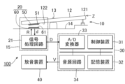
図1は、本開示のひとつの形態に係る変位センサーを適用した鍵盤楽器100の構成を例示するブロック図である。
鍵盤楽器100は、鍵盤10と検出システム15と情報処理装置30と放音装置40とを具備する電子楽器である。鍵盤10は、複数の白鍵と複数の黒鍵とを含む複数の鍵12で構成される。複数の鍵12の各々は、利用者による演奏動作に応じて変位する可動部材である。検出システム15は、鍵12の変位(位置)を検出する。情報処理装置30は、検出システム15による検出の結果に応じた音響信号Vを生成する。音響信号Vは、利用者が操作した鍵12に対応する音高の楽音を表す信号である。放音装置40は、音響信号Vが表す音響を放音する。例えばスピーカまたはヘッドホンが放音装置40として利用される。A: Embodiment FIG. 1 is a block diagram illustrating the configuration of a
A
図2は、鍵盤10のうち、1個の鍵12に着目して鍵盤楽器100の具体的な構成を例示するブロック図である。鍵盤10の各鍵12は、支点部13を支点として支持部材14に支持される。支持部材14は、鍵盤楽器100の各要素を支持する構造体である。各鍵12の端部121は、利用者による押鍵および離鍵により鉛直方向に変位する。検出システム15は、複数の鍵12の各々について、鉛直方向における端部121の位置Zに応じたレベルの検出信号Dを生成する。位置Zは、例えば、鍵12に荷重が作用しない解放状態における端部121の位置を基準とした当該端部121の変位量で表現される。
FIG. 2 is a block diagram illustrating a specific configuration of the
検出システム15は、鍵12毎に設けられる変位センサー20と各鍵12に共通の信号処理回路21とを具備する。変位センサー20は、各鍵12の位置を検出する位置センサーであり、被検出部50と信号生成部60とを含む。信号生成部60は、支持部材14に設置される。被検出部50は、鍵12に設置される。具体的には、被検出部50は、鍵12の底面(以下「設置面」という)122に設置される。被検出部50は第1コイル51を含む。信号生成部60は第2コイル61を含む。第1コイル51と第2コイル61とは、鉛直方向に相互に間隔をあけて対向する。信号生成部60と被検出部50との距離(第1コイル51と第2コイル61との距離)は、鍵12の端部121の位置Zが押鍵または離鍵により変化することに応じて変化する。信号処理回路21は、第1コイル51と第2コイル61との距離に応じたレベルの検出信号Dを生成する。
The
情報処理装置30は、信号処理回路21から供給される検出信号Dを解析することで各鍵12の位置Zを解析する。情報処理装置30は、制御装置31と記憶装置32とA/D変換器33と音源回路34とを具備するコンピュータシステムで実現される。
The
A/D変換器33は、信号処理回路21から供給される検出信号Dをアナログからデジタルに変換する。
制御装置31は、鍵盤楽器100の各要素を制御する単数または複数のプロセッサで構成される。例えば、制御装置31は、CPU(Central Processing Unit)、SPU(Sound Processing Unit)、DSP(Digital Signal Processor)、FPGA(Field Programmable Gate Array)、またはASIC(Application Specific Integrated Circuit)等の1種類以上のプロセッサで構成される。The A/
The
制御装置31は、A/D変換器33による変換後の検出信号Dを解析することで各鍵12の位置Zを解析する。また、制御装置31は、各鍵12の位置Zに応じた楽音の発音を音源回路34に対して指示する。音源回路34は、制御装置31から指示された楽音を表す音響信号Vを生成する。すなわち、音源回路34は、検出信号Dの電圧レベルδに応じて鍵が所定の位置に達したことを検出して音響信号Vの生成を開始する。そして、例えば電圧レベルδの速度変化に応じて音響信号Vの音量が制御される。音響信号Vが音源回路34から放音装置40に供給されることで、利用者による演奏動作に応じた楽音が放音装置40から放音される。具体的には、利用者による各鍵12の押鍵により楽音が放音され、当該鍵12の離鍵により楽音が停止される。
The
記憶装置32は、制御装置31が実行するプログラムと制御装置31が使用するデータとを記憶する単数または複数のメモリである。記憶装置32は、例えば磁気記録媒体または半導体記録媒体等の公知の記録媒体で構成される。なお、複数種の記録媒体の組合せにより記憶装置32を構成してもよい。また、鍵盤楽器100に着脱可能な可搬型の記録媒体、または、鍵盤楽器100が通信可能な外部記録媒体(例えばオンラインストレージ)を、記憶装置32として利用してもよい。なお、記憶装置32に記憶されたプログラムを実行することで制御装置31が音源回路34の機能を実現してもよい。音源回路34、または、音源回路34の機能を実現する制御装置31は、検出信号Dの電圧レベルδに応じた音響信号Vを生成する音制御部として機能する。
The
図3は、変位センサー20を構成する被検出部50と信号生成部60とにおける電気的な構成を例示する回路図である。
信号生成部60は、入力端子T1と出力端子T2と第2コイル61と容量素子62と容量素子63と抵抗素子64とを含む。信号生成部60では、共振回路が第2コイル61と容量素子62と容量素子63と抵抗素子64とによって構成される。入力端子T1は抵抗素子64の一端に接続され、抵抗素子64の他端は容量素子62の一端および第2コイル61の一端に接続される。第2コイル61の他端は出力端子T2および容量素子63の一端に接続される。容量素子62の他端および容量素子63の他端は電圧ゼロの基準である電位Gndに接地される。FIG. 3 is a circuit diagram illustrating an electrical configuration of the detected
The
一方、被検出部50は、第1コイル51と容量素子52とを含む。第1コイル51の一端と容量素子52の一端とが相互に接続され、第1コイル51の他端と容量素子52の他端とが相互に接続される。第1コイル51と容量素子52とによって共振回路が構成される。信号生成部60の共振周波数は、例えば被検出部50の共振周波数との関係に応じて設定される。設定される信号生成部60の共振周波数は、例えば、被検出部50の共振周波数とほぼ同等の周波数、または、被検出部50の共振周波数に所定の定数を乗算した周波数に設定される。
On the other hand, the detected
信号生成部60の入力端子T1には基準信号Rが供給される。基準信号Rは、周期的にレベルが変動する電圧信号である。例えば正弦波等の任意の波形の周期信号が基準信号Rとして利用される。基準信号Rの周波数は、被検出部50の共振周波数との関係等に応じて設定される。例えば、基準信号Rの周波数は、信号生成部60および被検出部50の共振周波数とほぼ同等である。
A reference signal R is supplied to the input terminal T1 of the
基準信号Rに応じた電流が第2コイル61に供給されることで、当該第2コイル61に磁界が発生する。第2コイル61に発生した磁界による電磁誘導で第1コイル51には誘導電流が発生する。したがって、第2コイル61の磁界の変化を相殺する方向の磁界が第1コイル51に発生する。第1コイル51に発生する磁界は、第1コイル51と第2コイル61との距離drに応じて変化する。このため、第1コイル51と第2コイル61との距離drに応じた電圧レベルδ(ピークトゥーピーク値)の検出信号dが信号生成部60の出力端子T2から出力される。検出信号dは、基準信号Rと同じ周期でレベルが変動する周期信号である。
A magnetic field is generated in the
図4は、信号処理回路21の具体的な構成を例示するブロック図である。信号処理回路21は、供給回路22と出力回路23とを具備する。供給回路22は、複数の信号生成部60の入力端子T1の各々に基準信号Rを供給する。供給回路22は、各信号生成部60に対して基準信号Rを時分割で供給する。具体的には、供給回路22は、複数の信号生成部60の各々を順次に選択し、選択状態の信号生成部60に対して基準信号Rを供給するデマルチプレクサである。すなわち、複数の信号生成部60の各々に対して時分割で基準信号Rが供給される。なお、基準信号Rの周期は、供給回路22が1個の信号生成部60を選択する期間の時間長よりも十分に短い。
FIG. 4 is a block diagram illustrating a specific configuration of the
出力回路23は、複数の信号生成部60の各々から順次に出力される検出信号dを時間軸上に配列することで検出信号Dを生成する。すなわち、検出信号Dは、各鍵12における第1コイル51と第2コイル61との距離drに応じた電圧レベルδの信号を時分割で示す信号である。前述の通り第1コイル51と第2コイル61との距離drは各鍵12の位置Zに相関するから、検出信号Dは、複数の鍵12の各々の位置Zに応じた信号となる。すなわち、1個の鍵12でみれば、検出信号dは、第1コイル51と、当該第1コイル51に対向する第2コイル61との相対位置に応じた信号と表現される。出力回路23が生成した検出信号Dは、情報処理装置30に供給される。
The
続いて、被検出部50と信号生成部60の構成について説明する。
図5は、当該被検出部50の具体的な構成を示す平面図であって、被検出部50を信号生成部60側からみた図である。図6は、図5におけるA-a線の断面図である。Next, the configurations of the detected
FIG. 5 is a plan view showing a specific configuration of the detected
被検出部50は、基板551と、当該基板551の表面F1および表面F2に設けられた配線パターンとを含む。基板551は、一例として、絶縁性を有する長方形状の板状部材である。被検出部50の表面F1は、鍵12の設置面122に取り付けられる面である。被検出部50の配線パターンは、基板551の表面F1およびF2に設けられた銅箔等の導電層のパターニングにより形成される。
なお、図5において上下方向が複数の鍵12が配列する方向であり、左右方向が1個の鍵12における長手方向である。鍵12の設置面122に取り付けられる被検出部50における幅Bwは、1個の鍵12の幅Kw以下である。Detected
5, the vertical direction is the direction in which the
また、表面F2は、表面F1とは反対側の表面である。このため、表面F2は信号生成部60に対向する。被検出部50の第1コイル51は、第1部分521と第2部分522とによって構成される。第1部分521および第2部分522は、基板551の表面F2に形成された配線パターンの一部である。第1部分521は、渦巻き状に形成された部分である。第2部分522は、第1部分521と略同じ形状に形成された部分である。すなわち、第2部分522は、第1部分521の巻方向と同方向の渦巻き状に形成される。
第1部分521の渦巻き中心はビアC1であり、第2部分522の渦巻き中心はビアC2である。ビアC1およびビアC2は表面F1の配線パターン515によって導通する。Further, the surface F2 is the surface opposite to the surface F1. Therefore, the surface F2 faces the
The spiral center of the
本実施形態において、第1部分521の渦巻きでは、ビアC1から延在する直線がほぼ90度ずつ屈曲して外側に向かって拡がる。第1部分521の外形は長方形である。同様に、第2部分522の渦巻きはビアC2から延在する直線がほぼ90度ずつ屈曲して外側に向かって拡がる。第2部分522の外形は長方形である。
第1部分521および第2部分522の外形は長方形状である。図5においては、第1部分521および第2部分522の各々について、基板551の長辺方向における外形寸法COLと、基板551の短辺方向における外形寸法COWとが図示されている。外形寸法COWは、基板551の短辺方向における第1コイル51の寸法(サイズ)に相当する。第1部分521および第2部分522の各々の外形寸法COWは、短辺方向における基板551の寸法Bw以下である。基板551の長辺方向は、第1部分521および第2部分522の並び方向、すなわち鍵12の長手方向に一致する。また、基板551の短辺方向は、第1部分521および第2部分522の並び方向に直交する方向、すなわち鍵12の幅方向に一致する。In this embodiment, in the spiral of the
The outlines of the
なお、ビアC1は第1部分521の中心に位置する。この中心は、第1部分521の外形である長方形の対角線が交差する地点である。同様に、ビアC2は第2部分522の中心に位置する。この中心は、第2部分522の外形である長方形の対角線が交差する地点である。
また、第1部分521の中心(ビアC1)と第2部分522の中心(ビアC2)との距離をL1とする。なお、距離L1は第1距離の一例である。Note that the via C<b>1 is positioned at the center of the
Also, the distance between the center of the first portion 521 (via C1) and the center of the second portion 522 (via C2) is L1. Note that the distance L1 is an example of the first distance.
第1部分521のビアC1を一端とした場合の当該第1部分521の他端と、第2部分522のビアC2を一端とした場合の当該第2部分522の他端との間に、容量素子52が実装される。したがって、被検出部50の等価回路は、図3に示したように第1コイル51の両端に容量素子52が接続された構成となる。
なお、本実施形態では、第1部分521および第2部分522を同一寸法、同一形状としたが、これに限定されるものではない。例えば、第1部分521および第2部分522の間で形状または寸法が相違してもよい。また、第1部分521と第2部分522との一方または双方の平面形状を、図5の縦方向が長手方向であり図5の横方向が短手方向である矩形状としてもよい。また、第1コイル51の平面形状は、第1部分521と第2部分522とを含む形状に限定されない。すなわち、第1コイル51は、ひとつの巻回部で構成されてもよい。A
Although the
図8は、信号生成部60の具体的な構成を示す平面図であって、信号生成部60を被検出部50側からみた図である。また、図9は、図8におけるB-b線の断面図である。
FIG. 8 is a plan view showing a specific configuration of the
信号生成部60は、基板651と、当該基板651の表面F3および表面F4に設けられた配線パターンとを含む。基板651は、絶縁性を有する板状部材である。信号生成部60の表面F4は、支持部材14に対向する。表面F3は、表面F4とは反対側の表面であり、被検出部50に対向する。配線パターンは、基板651の表面F3およびF4に設けられた銅箔等の導電層のパターニングにより形成される。
The
図8における上下方向は、複数の鍵12(図8においては図示略)が配列する方向である。図8における左右方向は、1個の鍵12における長手方向である。鍵12の長手方向とは、当該鍵12の先端側(演奏者側)から鍵12の根元側に向かう方向である。
The vertical direction in FIG. 8 is the direction in which a plurality of keys 12 (not shown in FIG. 8) are arranged. The horizontal direction in FIG. 8 is the longitudinal direction of one
信号生成部60の第2コイル61は、第3部分621と第4部分622とによって構成される。第3部分621および第4部分622は、表面F3に形成された配線パターンの一部である。第3部分621は、略正方形状で渦巻き状に形成された部分である。第4部分622は、第3部分621と略同じ形状に形成された部分である。すなわち、第4部分622は、第3部分621の巻方向と同方向の渦巻き状に形成される。
第3部分621の渦巻き中心はビアC11であり、第4部分622の渦巻き中心はビアC12である。ビアC11およびビアC12が表面F4の配線パターン612によって導通する。
なお、本実施形態では、第3部分621および第4部分622を同一寸法、同一形状としたが、これに限定されるものではない。例えば、第3部分621および第4部分622の間で寸法が相違してもよい。また、第3部分621および第4部分622を互いに異なる形状としてもよい。また、第2コイル61の平面形状は、第3部分621と第4部分622とを含む形状に限定されない。すなわち、第2コイル61は、ひとつの巻回部で構成されてもよい。The
The spiral center of the
Although the
本実施形態において、第3部分621の外形は略正方形である。同様に、第4部分622の外形は略正方形である。
第3部分621および第4部分622の外形である正方形の一辺の方向は、鍵12の長手方向に一致し、当該一辺に直交する方向は、鍵12の幅方向に一致する。当該正方形の1辺の寸法(外形寸法)をB2とする。In this embodiment, the outer shape of the
The direction of one side of the square that is the outer shape of the
なお、ビアC11は第3部分621の中心に位置し、ビアC12は第4部分622の中心に位置する。ここでいう中心は、平面視におけるコイルの中心であり、正方形または長方形であれば対角線が交差する地点であり、円形であれば外円の中心である。
また、第3部分621の中心(本実施形態ではビアC11)と第4部分622の中心(本実施形態ではビアC12)との距離をL2とする。なお、距離L2は第2距離の一例である。The via C11 is located in the center of the
Also, the distance between the center of the third portion 621 (the via C11 in this embodiment) and the center of the fourth portion 622 (the via C12 in this embodiment) is L2. Note that the distance L2 is an example of the second distance.
表面F3の配線パターンのうち、第2コイル61以外の部分は、容量素子62および容量素子63、抵抗素子64、入力端子T1および出力端子T2を接続するための配線である。前述の通り、入力端子T1には、基準信号Rが供給回路22から供給され、出力端子T2からは、第1コイル51と第2コイル61との距離drに応じた電圧レベルδの検出信号dが出力される。
被検出部50と信号生成部60の以上の構成において、第1部分521と第3部分621とが対向し、第2部分522と第4部分622とが対向する。そして、一例であるが、寸法関係として、COW=B2×70%、COL=B2となっている。Of the wiring pattern on the surface F3, portions other than the
In the above configurations of the detected
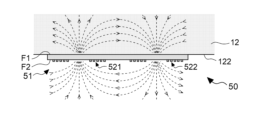
次に、被検出部50と信号生成部60における回路の動作について説明する。図7は、被検出部50により発生する磁界方向の一例を示す図である。図10は、信号生成部60により発生する磁界方向の一例を示す図である。
信号生成部60に対する基準信号Rの供給により、例えば図8においてビアC11を起点に反時計回りの電流が第3部分621に流れる場合、ビアC12に向かって時計回りの電流が第4部分622に流れる。このため、磁界は、第3部分621においては、図8の紙面手前方向および図10の上方向に発生し、第4部分622においては、図8の紙面奧方向および図10の下方向に発生する。Next, circuit operations in the detected
When the reference signal R is supplied to the
すなわち、図10に例示される通り、第3部分621と第4部分622とでは互いに逆方向の磁界が発生する。前述の通り、鍵盤10において複数の鍵12が図10の紙面垂直方向に配列する。したがって、第3部分621と第4部分622とで逆方向の磁界が発生することで、相互に隣り合う各鍵12に対向する信号生成部60で発生する磁界の拡散が低減される。磁界の拡散が低減される結果、複数の鍵12の各々の位置Zを高精度に反映した検出信号Dが生成される。
That is, as illustrated in FIG. 10, magnetic fields in opposite directions are generated in the
なお、図10においては、図8において第3部分621に反時計回りの電流が流れ、第4部分622に時計回りの電流が流れる場合が例示されている。第3部分621に時計回りの電流が流れ、第4部分622に反時計回りの電流が流れる場合にも同様に、磁界の方向は逆向きとなる。
Note that FIG. 10 illustrates a case where a counterclockwise current flows through the
信号生成部60における第2コイル61の第3部分621および第4部分622は、表面F4の導電層のパターニングにより形成される。このため、例えば第2コイル61を導電線の巻回により形成する構成と比較して、第2コイル61の製造および取扱が容易であるという利点がある。
The
このように、信号生成部60に基準信号Rが供給された状態において、第1コイル51が第2コイル61から離れる方向に移動する場合、第1コイル51には、第2コイル61により生成される磁界が減るのを阻止する方向の磁界(すなわち、第2コイル61の発生磁界と同方向の磁界が)発生する。したがって、この場合、第1コイル51には、第2コイル61により生成される磁界と同方向の磁界に応じた電流が誘起される。
例えば、図10に示される方向の磁界が信号生成部60の第2コイル61によって発生した状態で、被検出部50の第1コイル51が第2コイル61に離れる方向に移動する場合、第1コイル51には、第2コイル61により生成される磁界と同方向の磁界が発生する。
このため、図5において、第1コイル51の第1部分521には電流が時計回りで流れ、第2部分522には電流が反時計回りで流れる。
また、図10に示される方向の磁界が信号生成部60の第2コイル61によって発生した状態で、被検出部50の第1コイル51が第2コイル61に接近する方向に移動する場合、第1コイル51には、第2コイル61により生成される磁界とは逆方向の磁界が発生する。
このため、図5において、第1コイル51の第1部分521には電流が反時計回りで流れ、第2部分522には電流が時計回りで流れる。In this way, when the
For example, when the magnetic field in the direction shown in FIG. A magnetic field in the same direction as the magnetic field generated by the
Therefore, in FIG. 5, the current flows clockwise through the
10 is generated by the
Therefore, in FIG. 5, the current flows counterclockwise through the
なお、図10に例示された方向とは反対の方向の磁界が第2コイル61に発生した状態で、第1コイル51が第2コイル61に近づく場合、第2コイル61により生成される磁界と逆方向の磁界、すなわち、図7に示されるような磁界が、第1コイル51に発生する。
また、図10に示される方向の磁界が第2コイル61によって発生した状態で、第1コイル51が第2コイル61に近づく場合、および、図10に示される方向とは反対の方向の磁界が第2コイル61に発生した状態で、第1コイル51が第2コイル61から離れる場合には、第1コイル51の第1部分521には電流が時計回りで流れ、第2部分522には電流が反時計回りで流れる。Note that when the
10, and when the
続いて、検出システム15において、検出信号の出力特性に関するリニアリティを向上させる、すなわち検出距離を長くする構成及び処理について説明する。出力特性は、第1コイル51と第2コイル61との間の距離drと、検出信号dの電圧レベルδとの関係である。出力特性のリニアリティとは、距離drに対する電圧レベルδの関係が比例関係に近いことを意味する。また、検出距離は、距離drの変化に対して電圧レベルδが有意に変化する当該距離drの範囲(検出範囲)の幅を意味する。すなわち、検出距離は、電圧レベルδに反映される距離drの範囲を意味する。
Next, in the
出力特性のリニアリティを向上させるために、本実施形態では、第1部分521の中心と第2部分522の中心との距離L1(第1距離)が、第3部分621の中心と第4部分622の中心との距離L2(第2距離)を上回る。
In order to improve the linearity of the output characteristics, in the present embodiment, the distance L1 (first distance) between the center of the
図11は、被検出部50が鍵12の設置面122に取り付けられ、信号生成部60が支持部材14に設置された状態で、第1コイル51および第2コイル61の位置関係を示す平面図である。詳細には、図11は、上記状態において、第1コイル51における第1部分521および第2部分522と、第2コイル61における第3部分621および第4部分622と、を被検出部50から信号生成部60に向かって透視した場合の平面図である。
11 is a plan view showing the positional relationship between the
ビアC1、C2、C11およびC12は、鍵12における長手方向に沿った直線Ln上に位置する。また、ビアC1およびビアC2の間に、ビアC11およびC12が位置する。
Vias C1, C2, C11 and C12 are located on straight line Ln along the longitudinal direction of
本実施形態に係る変位センサー20では、被検出部50における第1部分521の中心と第2部分522の中心との距離L1が、信号生成部60における第3部分621の中心と第4部分622の中心との距離L2を上回る。そこでまず、距離L1が距離L2を上回る構成の有効性について説明する。
In the
距離L1と距離L2との大小を相違させた構成Aと構成Bとの間で出力特性を比較する。構成Aは、図12に示されるように第1コイル51における距離L1が距離L2を上回る構成である。構成Bは、図13に示されるように、第1コイル51における距離L1が距離L2を下回る構成である。
具体的には、図12において距離L1は図8に示すL2×120%であり、図13において距離L1はL2×80%である。なお、図12における外形寸法COLおよびCOWと、図13における外形寸法COLおよびCOWとは、図8に示す外形寸法B2×70%の長さである。この比較における信号生成部60は、図8の構成を用いている。The output characteristics are compared between the configuration A and the configuration B in which the distance L1 and the distance L2 are different. Configuration A is a configuration in which the distance L1 in the
Specifically, the distance L1 in FIG. 12 is L2×120% shown in FIG. 8, and the distance L1 is L2×80% in FIG. The outer dimensions COL and COW in FIG. 12 and the outer dimensions COL and COW in FIG. 13 are the length of the outer dimensions B2×70% shown in FIG. The
図14は、構成Aおよび構成Bにおける変位センサー20の出力特性を示す図である。図14において、縦軸は検出信号dの電圧レベルδ[V]であり、横軸は変位Zの位置に応じた距離、具体的には、第1コイル51と第2コイル61との距離drである。また、図14において、実線は、図12に示される構成Aの出力特性を示し、破線は、図13に示される構成Bの出力特性を示す。構成Aでは、距離drが10mmを超えても出力電圧が増える方向に変化しているのに対して、構成Bでは、距離drが8mmを超えると出力電圧が変化しなくなる(ほぼ一定値になる)。
14A and 14B are diagrams showing output characteristics of the
つまり、構成Aおよび構成Bの出力特性を比較すると、実線の構成Aでは、破線の構成Bよりも、検出信号dの出力変化が得られる距離drの範囲が広い、すなわち、変位センサー20が検出できる範囲が広いことが判る。言い換えれば、実線の構成Aでは、破線の構成Bよりも、出力特性において高いリニアリティが得られているといえる。 That is, when comparing the output characteristics of the configuration A and the configuration B, in the configuration A indicated by the solid line, the range of the distance dr at which the output change of the detection signal d can be obtained is wider than in the configuration B indicated by the broken line. It can be seen that the possible range is wide. In other words, it can be said that the configuration A represented by the solid line provides higher linearity in the output characteristics than the configuration B represented by the broken line.
また、出力特性のリニアリティを向上させるための別の方策として、本実施形態では、被検出部50における第1部分521および第2部分522の外形が、図12に示される正方形ではなく、鍵12の長手方向に延在する長方形となっている。
In addition, as another measure for improving the linearity of the output characteristics, in the present embodiment, the external shapes of the
そして、第1部分521および第2部分522においてコイルとして機能する領域が広いことが好ましい。このため、本実施形態では、被検出部50における第1部分521および第2部分522のそれぞれの外形が、鍵12の長手方向に沿う長方形とされる。具体的には、本実施形態では、第1部分521および第2部分522の各々の外形寸法COLが、外形寸法COWを上回る。具体的には、本実施形態では、第1部分521および第2部分522の各々において、外形寸法COWと外形寸法COLとの寸法比を7:10としている。
In addition, it is preferable that the
次に、距離L1と距離L2との関係について検討する。図15は、距離L2を基準とした距離L1の比率(%)を100%、120%、140%、160%に変化させたときの出力特性を示す図である。なお、縦軸の電圧レベルδは、比較のために、最低値が「0」、最大値が「1」となるように正規化されている。この検討における信号生成部60は、図8の構成を用いている。
Next, the relationship between the distance L1 and the distance L2 will be examined. FIG. 15 is a diagram showing output characteristics when the ratio (%) of the distance L1 to the distance L2 is changed to 100%, 120%, 140%, and 160%. For comparison, the voltage level δ on the vertical axis is normalized so that the minimum value is "0" and the maximum value is "1". The
この図に示される4つの出力特性のうち、リニアリティを示す指標(例えばR自乗値)が最も高くなるのは距離L1がL2×120%のときであり、最も低くなるのは距離L1がL2×160%のときである。このため、リニアリティを確保するという観点からいえば、距離L1は、距離L2を基準として120%の前後値を含む範囲内の数値であることが好ましい。具体的には、距離L1は、距離L2に対して100%を上回り、かつ、140%以下の範囲(L2<L1≦1.4×L2)内の数値に設定される。 Among the four output characteristics shown in this figure, the linearity index (for example, the R-squared value) is highest when the distance L1 is L2×120%, and is lowest when the distance L1 is L2×120%. When it is 160%. Therefore, from the viewpoint of ensuring linearity, the distance L1 is preferably a numerical value within a range including 120% of the distance L2 as a reference. Specifically, the distance L1 is set to a numerical value within a range (L2<L1≦1.4×L2) exceeding 100% and 140% or less of the distance L2.
このように距離L1を距離L2に対して上記範囲内となるように設定すると、第2コイル61で発生した磁界が適度に減少して第1コイル51に到達するため、検出信号dの出力特性に関するリニアリティが高められる。また、距離L1を距離L2に対して上記範囲内となるように設定すると、第2コイル61に対する第1コイル51が位置ずれしても、上記範囲外となるように設定した場合と比較して、出力特性のリニアリティが損なわれることがない。
When the distance L1 is set to be within the above range with respect to the distance L2 in this way, the magnetic field generated by the
1:出力特性のリニアリティを向上させる方策1
上述した実施形態のほかに、出力特性のリニアリティを向上させるための方策としては、第1に、信号生成部60における共振回路にダンピング抵抗として抵抗素子64を使用して共振回路のQ値(Quality Factor)を下げることが挙げられる。
図16は、図3の回路における抵抗素子64の抵抗値を段階的に変化させた場合における出力特性を示す図である。図16においては、抵抗素子64の抵抗値を、0、100、200、300、400および500Ωの6通りに変化させた各場合について出力特性が図示されている。1:
In addition to the above-described embodiments, as a measure for improving the linearity of the output characteristics, firstly, a
FIG. 16 is a diagram showing output characteristics when the resistance value of the
図16において、抵抗素子64がない状態(0Ω)、すなわち最もQ値が高い状態では、距離drが5mmを少し超えたところで検出信号dの電圧レベルδが最大になり、その後は距離drの増加に対して電圧レベルδが低下する特性となる。したがって、検出範囲としては、1~5mm程度の狭い範囲しか使えない。ところが、Q値を下げるように100Ωの抵抗素子64を使用した状態では、距離drが5mmを上回る範囲でも、距離drの増加に対して検出信号dの電圧レベルδがわずかずつだが増える特性となる。そして、抵抗素子64の抵抗値が増えるにしたがって、距離drが小さい範囲(例えば1~3mm)、大きい範囲(例えば、8~10mm)、それらの中間の範囲(例えば、4~6mm)のそれぞれで電圧レベルδの変化幅が小さくなっていく。
In FIG. 16, when the
このように、信号生成部60における抵抗素子64の抵抗値が大きくなるにつれて、Q値が下がり、出力特性のリニアリティが高くなる。すなわち、検出距離を大きくすることができる。
なお、被検出部50には、ダンピング抵抗としての抵抗素子は設置されない。これは、Q値を下げなくても、十分な検出特性が得られるからである。ただし、検出の安定性や装置の量産性のために、ダンピング抵抗としての抵抗素子を被検出部50に設置してもよい。Thus, as the resistance value of the
It should be noted that no resistive element as a damping resistor is installed in the detected
2:出力特性のリニアリティを向上させる方策2
また、出力特性のリニアリティを向上させるための他の方策としては、入力端子T1に供給される基準信号Rの周波数を、被検出部50の共振周波数より最大2%までの間(すなわち当該共振周波数の98%から100%までの間)で低くする、より好ましくは被検出部50の共振周波数よりも約1%低くすることが挙げられる。2:
Further, as another measure for improving the linearity of the output characteristics, the frequency of the reference signal R supplied to the input terminal T1 is set to a maximum of 2% from the resonance frequency of the detected section 50 (that is, the resonance frequency from 98% to 100%), more preferably about 1% lower than the resonance frequency of the detected
図17は、本実施形態において、被検出部50(第1コイル51のリアクタンスが3.04μH、容量素子52の容量が220pF)の共振周波数を6.15MHzとして、基準信号Rの周波数を段階的に変化させた場合における出力特性を示す図である。図17においては、基準信号Rの周波数を、6.00MHz、6.05MHz、6.10MHz、6.15MHz、6.20MHz、6.25MHzおよび6.30MHzの7通りに変化させた各場合について出力特性が図示されている。図17において、基準信号Rの周波数が6.15MHzより高い周波数(6.20MHz、6.25MHz,6.30MHz)である場合は、被検出部50の共振周波数と同じ周波数の基準信号Rを使用したときに比べて、距離drが小さい範囲(例えば1~3mm)や中間の範囲(例えば、4~6mm)における出力信号の増加の傾きが大きくなるが、7mmより大きい範囲ではその出力特性を維持できていない。さらに基準信号Rの周波数が6.25MHzや6.30MHzである場合、距離drが6mm以上の範囲においては、電圧レベルδが距離drの増加に対して低下しており、検出の用途に適さない。一方で、基準信号Rの周波数が6.15MHzより最大2%までの低い周波数であれば、検出に適するリニアリティが得られる。さらには、基準信号Rの周波数を、被検出部50の共振周波数よりも約1%低い6.10MHzにすると、出力特性のリニアリティがより高くなる。
FIG. 17 shows that, in this embodiment, the resonance frequency of the detected part 50 (the reactance of the
なお、信号生成部60における共振回路のQ値を下げる場合(方策1)、および、基準信号Rの周波数を被検出部50の共振周波数よりも低くする場合(方策2)の何れにおいても、リニアリティを最大にする最適解が存在する。この最適解についてはコンピューターによる数値解析により求めることができる。 In both cases of lowering the Q value of the resonance circuit in the signal generation unit 60 (measure 1) and making the frequency of the reference signal R lower than the resonance frequency of the detected unit 50 (measure 2), the linearity There exists an optimal solution that maximizes This optimum solution can be obtained by numerical analysis using a computer.
実施形態では、第1部分521、第2部分522、第3部分621および第4部分622の外形を、正方形を含む長方形としたが、菱形などの他の四角形でもよいし、真円や楕円などの円形であってもよい。なお、この場合の中心は、四角形であれば対角線の交点であり、真円であれば中心であり、楕円であれば長軸と短軸の交点である。
In the embodiment, the outer shapes of the
B:変形例
以上に例示した各態様に付加される具体的な変形の態様を以下に例示する。以下の例示から任意に選択された2以上の態様を、相互に矛盾しない範囲で適宜に併合してもよい。B: Modifications Examples of specific modifications added to the above-exemplified embodiments are given below. Two or more aspects arbitrarily selected from the following examples may be combined as appropriate within a mutually consistent range.
(1)上述した各形態においては、鍵盤楽器100の鍵12の変位を検出する構成を例示したが、変位センサー20により変位が検出される可動部材は鍵12に限定されない。また、鍵盤構造についても、上述の例の構造に限定されない。上述の例と異なる可動部材の具体的な態様を以下に例示する。
(1) In each of the above embodiments, the configuration for detecting the displacement of the
[態様1]
図18は、鍵盤楽器100の打弦機構91に変位センサー20を適用した構成の模式図である。打弦機構91は、鍵盤10の各鍵12の変位に連動して弦(図示略)を打撃するアクション機構である。具体的には、打弦機構91は、回動により打弦可能なハンマー911と、鍵12の変位に連動してハンマー911を回動させる伝達機構912(例えばウィペン、ジャック、レペティションレバー等)とを、鍵12毎に具備する。
被検出部50がハンマー911(例えばハンマーシャンク)に設置される。また、信号生成部60は支持部材913に設置される。このような構成において、変位センサー20は、ハンマー911の変位を検出する。具体的には、支持部材913は、例えば打弦機構91を支持する構造体である。なお、被検出部50は、打弦機構91におけるハンマー911以外の可動部材に設置してもよい。[Aspect 1]
FIG. 18 is a schematic diagram of a configuration in which the
A detected
[態様2]
図19は、鍵盤楽器100のペダル機構92に変位センサー20を適用した構成の模式図である。ペダル機構92は、利用者が足で操作するペダル921と、ペダル921を支持する支持部材922と、鉛直方向の上方にペダル921を付勢する弾性体923とを具備する。
被検出部50がペダル921の底面に設置される。また、信号生成部60は、被検出部50に対向するように支持部材922に設置される。このような構成において、変位センサー20はペダル921の変位を検出する。
なお、ペダル機構92が利用される楽器は鍵盤楽器100に限定されない。例えば打楽器等の任意の楽器にも同様の構成のペダル機構92が利用される。[Aspect 2]
FIG. 19 is a schematic diagram of a configuration in which the
A detected
Note that the musical instrument using the
以上の例示から理解される通り、変位センサーによる検出の対象は、演奏動作に応じて変位する可動部材として包括的に表現される。可動部材は、利用者が直接的に操作する鍵12またはペダル921等の演奏操作子のほか、演奏操作子に対する操作に連動して変位するハンマー911等の構造体を含む。ただし、本開示における可動部材は、演奏動作に応じて変位する部材に限定されない。すなわち、可動部材は、変位を発生させる契機に関わらず、変位可能な部材として包括的に表現される。
As can be understood from the above examples, the objects to be detected by the displacement sensor are comprehensively represented as movable members that are displaced according to the performance action. The movable members include performance operators such as the
(2)前述の形態においては、鍵盤楽器100が音源回路34を具備する構成を例示したが、例えば鍵盤楽器100が打弦機構91等の発音機構を具備する構成においては、音源回路34を省略してもよい。検出システム15は、鍵盤楽器100の演奏内容を記録するために利用される。発音機構および音源回路34は、検出システム15による検出の結果に応じて音を生成する音生成部として包括的に表現される。
(2) In the above embodiment, the
以上の説明から理解される通り、本開示は、音源回路34または発音機構に対して演奏動作に応じた操作信号を出力することで楽音を制御する装置(演奏操作装置)としても特定される。前述の各形態の例示のように音源回路34または発音機構を具備する楽器(鍵盤楽器100)のほか、音源回路34または発音機構を具備しない機器(例えばMIDIコントローラまたは前述のペダル機構92)が、演奏操作装置(instrument playing apparatus)の概念には包含される。すなわち、本開示における演奏操作装置は、演奏者(操作者)が演奏のために操作する装置として包括的に表現される。
As can be understood from the above description, the present disclosure is also specified as a device (performance operation device) that controls musical tones by outputting operation signals corresponding to performance operations to the
(3)上述の出力特性のリニアリティを向上させるための方策は、どれかひとつを実施してもよいし、2以上の方策を適宜に併用してもよい。 (3) Any one of the measures for improving the linearity of the output characteristics described above may be implemented, or two or more measures may be used in combination as appropriate.
C:付記
上述した実施形態等から、例えば以下のような態様が把握される。C: Supplementary Notes The following aspects, for example, can be understood from the above-described embodiments and the like.
本開示の態様(第1態様)に係る変位センサーは、操作に応じて変位する可動部材に設置され、第1コイルを含む被検出部と、前記第1コイルに対向する第2コイルを含み、前記第1コイルと前記第2コイルとの相対位置に応じた検出信号を生成する信号生成部と、を具備し、第1方向における前記第1コイルの外形寸法と、前記第1方向に直交する第2方向における前記第1コイルの外形寸法とは平面視で異なる。
この態様によれば、被検出部の第1コイルと対向する前記第2コイルとの相対位置の変化に応じて検出信号が変化する際のリニアリティが向上するので、可動部材の変位を高精度に反映した検出信号を生成することができる。このため、測距距離を伸ばすことができる。A displacement sensor according to an aspect (first aspect) of the present disclosure is installed on a movable member that is displaced according to an operation, and includes a detected part including a first coil, and a second coil facing the first coil, a signal generator that generates a detection signal corresponding to the relative position of the first coil and the second coil, wherein the external dimensions of the first coil in a first direction are perpendicular to the first direction. It is different from the outer dimensions of the first coil in the second direction in plan view.
According to this aspect, since the linearity is improved when the detection signal changes in accordance with the change in the relative position between the first coil of the detected portion and the second coil facing the first coil, the displacement of the movable member can be performed with high accuracy. A reflected detection signal can be generated. Therefore, the range-finding distance can be extended.
特定の方向におけるコイルの「外形寸法」とは、当該コイルの外形を表す輪郭線に関する当該方向における寸法(サイズ)を意味し、当該方向におけるコイルの寸法の最大値とも換言される。 The “outer dimension” of a coil in a specific direction means the dimension (size) in that direction with respect to the outline representing the outer shape of the coil, and can also be rephrased as the maximum dimension of the coil in that direction.
第1態様の例(第2態様)において、前記被検出部は、前記第1コイルが形成された長方形状の基板を含み、前記第1方向は前記基板の長辺方向であり、前記第2方向は前記基板の短辺方向であり、前記第2方向における前記第1コイルの外形寸法は、前記短辺方向における前記基板の寸法以下である。 In the example of the first aspect (the second aspect), the detected part includes a rectangular substrate on which the first coil is formed, the first direction is the long side direction of the substrate, and the second The direction is the short side direction of the substrate, and the outer dimensions of the first coil in the second direction are equal to or less than the dimensions of the substrate in the short side direction.
本開示の別の態様(第3態様)において、前記第1方向における前記第1コイルの外形寸法は、前記第2方向における前記第1コイルの外形寸法を上回る。 In another aspect (third aspect) of the present disclosure, the external dimension of the first coil in the first direction is greater than the external dimension of the first coil in the second direction.
また、本開示の別の態様(第4態様)に係る変位センサーは、操作に応じて変位する可動部材に設置され、第1コイルを含む被検出部と、前記第1コイルに対向する第2コイルを含み、前記第1コイルと前記第2コイルとの相対位置に応じた検出信号を生成する信号生成部と、を具備し、前記第1コイルは、当該第1コイルに対する電流の供給により相互に逆向きの磁界が発生する第1部分および第2部分を有し、前記第2コイルは、当該第2コイルに対する電流の供給により相互に逆向きの磁界が発生する第3部分および第4部分を有し、前記第1部分の中心と前記第2部分の中心との第1距離は、前記第3部分の中心と前記第4部分の中心との第2距離を上回る。
この態様によれば、被検出部の第1コイルと対向する前記第2コイルとの相対位置の変化に応じて検出信号が変化する際のリニアリティが向上するので、可動部材の変位を高精度に反映した検出信号を生成することができる。また、第2コイルにより発生じた磁界の漏れが低減されるので、検出精度を高めることができる。Further, a displacement sensor according to another aspect (fourth aspect) of the present disclosure is provided on a movable member that is displaced according to an operation, and includes a detected part including a first coil and a second detection part facing the first coil. a signal generator that includes a coil and generates a detection signal according to the relative position of the first coil and the second coil, wherein the first coil is mutually connected by supplying current to the first coil; The second coil has a first portion and a second portion that generate magnetic fields in directions opposite to each other, and the second coil includes a third portion and a fourth portion that generate magnetic fields in directions opposite to each other by supplying a current to the second coil. and a first distance between the center of the first portion and the center of the second portion is greater than a second distance between the center of the third portion and the center of the fourth portion.
According to this aspect, since the linearity is improved when the detection signal changes in accordance with the change in the relative position between the first coil of the detected portion and the second coil facing the first coil, the displacement of the movable member can be performed with high accuracy. A reflected detection signal can be generated. Moreover, since leakage of the magnetic field generated by the second coil is reduced, detection accuracy can be improved.
第4態様の例(第5態様)において、前記第1距離は、前記第2距離の100%を上回り、かつ140%以下である。 In an example of the fourth aspect (fifth aspect), the first distance is more than 100% and less than or equal to 140% of the second distance.
本開示のひとつの態様(第6態様)に係る電子楽器は、以上に例示した何れかの態様に係る変位センサーと、前記検出信号のレベルに応じた音を表す音響信号を生成する音制御部とを具備する。 An electronic musical instrument according to one aspect (sixth aspect) of the present disclosure includes: a displacement sensor according to any one of the above-described aspects; and
本開示の別の態様(第7態様)に係る変位センサーは、操作に応じて変位する可動部材に設置され、第1コイルを形成した基板を含む被検出部と、第2コイルを含み、前記被検出部の第1コイルとそれに対向する前記第2コイルとの相対位置に応じた検出信号を生成する信号生成部と具備し、前記被検出部と前記信号生成部はともに共振回路で形成し、前記信号生成部はQ値を下げる抵抗素子を有し、被検出部はQ値を下げる抵抗素子を有していない。 A displacement sensor according to another aspect (seventh aspect) of the present disclosure is provided on a movable member that is displaced according to an operation, includes a detected part including a substrate on which a first coil is formed, and a second coil, and a signal generator for generating a detection signal according to the relative position of the first coil of the detected part and the second coil facing the first coil, and the detected part and the signal generator are both formed of a resonance circuit. , the signal generator has a resistance element that lowers the Q value, and the detected part does not have a resistance element that lowers the Q value.
本開示の別の態様(第8態様)に係る変位センサーは、操作に応じて変位する可動部材に設置され、第1コイルを形成した基板を含む被検出部と、第2コイルを含み、前記被検出部の第1コイルとそれに対向する前記第2コイルとの相対位置に応じた検出信号を生成する信号生成部と具備し、前記信号生成部の検出信号の周波数は、被検出部の共振周波数より差が最大2%までの間(すなわち共振周波数の98%から100%までの間)で低い。 A displacement sensor according to another aspect (eighth aspect) of the present disclosure is provided on a movable member that is displaced according to an operation, includes a detected part including a substrate on which a first coil is formed, and a second coil, a signal generator for generating a detection signal according to the relative position of the first coil of the detected part and the second coil facing the first coil, wherein the frequency of the detection signal of the signal generator is the resonance of the detected part The difference is up to 2% lower than the frequency (ie between 98% and 100% of the resonant frequency).
100…鍵盤楽器(電子楽器)、10…鍵盤、12…鍵、15…検出システム、20…変位センサー、21…信号処理回路、22…供給回路、23…出力回路、30…情報処理装置、31…制御装置、32…記憶装置、33…A/D変換器、34…音源回路、40…放音装置、50…被検出部、51…第1コイル、52…容量素子、521…第1部分、522…第2部分、551…基板、523…第3部分、524…第4部分、551、552、553…基板、60…信号生成部、61…第2コイル、612…配線パターン、621…第3部分、622…第4部分、651…基板、62…容量素子、63…容量素子、64…抵抗素子、911…ハンマー、912…伝達機構、913…支持部材、921…ペダル、922…支持部材、923…弾性体。
DESCRIPTION OF
Claims (3)
前記第1コイルに対向する第2コイルを含み、前記第1コイルと前記第2コイルとの相対位置に応じた検出信号を生成する信号生成部と、
を具備し、
前記第1コイルは、当該第1コイルに対する電流の供給により相互に逆向きの磁界が発生する第1部分および第2部分を有し、
前記第2コイルは、当該第2コイルに対する電流の供給により相互に逆向きの磁界が発生する第3部分および第4部分を有し、
前記第1部分の中心と前記第2部分の中心との第1距離は、前記第3部分の中心と前記第4部分の中心との第2距離を上回る
変位センサー。 a detected part that is installed on a movable member that is displaced according to an operation and includes a first coil;
a signal generator that includes a second coil facing the first coil and generates a detection signal according to the relative position of the first coil and the second coil;
and
the first coil has a first portion and a second portion in which magnetic fields in opposite directions are generated by supplying current to the first coil;
the second coil has a third portion and a fourth portion in which magnetic fields in opposite directions are generated by supplying current to the second coil;
A first distance between the center of the first portion and the center of the second portion is greater than a second distance between the center of the third portion and the center of the fourth portion.
請求項1に記載の変位センサー。 2. The displacement sensor of claim 1 , wherein the first distance is greater than 100% and less than or equal to 140% of the second distance.
前記検出信号のレベルに応じた音を表す音響信号を生成する音制御部と、
を具備する電子楽器。
a displacement sensor according to claim 1 or claim 2 ;
a sound control unit that generates an acoustic signal representing a sound corresponding to the level of the detection signal;
An electronic musical instrument comprising
Priority Applications (1)
| Application Number | Priority Date | Filing Date | Title |
|---|---|---|---|
| JP2023076647A JP2023087103A (en) | 2020-03-26 | 2023-05-08 | Displacement sensor and electronic musical instrument |
Applications Claiming Priority (3)
| Application Number | Priority Date | Filing Date | Title |
|---|---|---|---|
| JP2020056224 | 2020-03-26 | ||
| JP2020056224 | 2020-03-26 | ||
| PCT/JP2021/011266 WO2021193389A1 (en) | 2020-03-26 | 2021-03-18 | Displacement sensor and electronic musical instrument |
Related Child Applications (1)
| Application Number | Title | Priority Date | Filing Date |
|---|---|---|---|
| JP2023076647A Division JP2023087103A (en) | 2020-03-26 | 2023-05-08 | Displacement sensor and electronic musical instrument |
Publications (3)
| Publication Number | Publication Date |
|---|---|
| JPWO2021193389A1 JPWO2021193389A1 (en) | 2021-09-30 |
| JPWO2021193389A5 JPWO2021193389A5 (en) | 2022-11-30 |
| JP7302739B2 true JP7302739B2 (en) | 2023-07-04 |
Family
ID=77891744
Family Applications (2)
| Application Number | Title | Priority Date | Filing Date |
|---|---|---|---|
| JP2022510061A Active JP7302739B2 (en) | 2020-03-26 | 2021-03-18 | Displacement sensors and electronic instruments |
| JP2023076647A Pending JP2023087103A (en) | 2020-03-26 | 2023-05-08 | Displacement sensor and electronic musical instrument |
Family Applications After (1)
| Application Number | Title | Priority Date | Filing Date |
|---|---|---|---|
| JP2023076647A Pending JP2023087103A (en) | 2020-03-26 | 2023-05-08 | Displacement sensor and electronic musical instrument |
Country Status (5)
| Country | Link |
|---|---|
| US (1) | US20230013774A1 (en) |
| EP (1) | EP4130645A4 (en) |
| JP (2) | JP7302739B2 (en) |
| CN (1) | CN115298510A (en) |
| WO (1) | WO2021193389A1 (en) |
Families Citing this family (3)
| Publication number | Priority date | Publication date | Assignee | Title |
|---|---|---|---|---|
| GB2570533B (en) * | 2017-12-20 | 2021-09-22 | Sonuus Ltd | Keyboard sensor systems and methods |
| WO2021100868A1 (en) * | 2019-11-20 | 2021-05-27 | ヤマハ株式会社 | Detection device for key operation of keyboard device, detection method for key operation, and keyboard device |
| JP7443984B2 (en) * | 2020-08-20 | 2024-03-06 | ヤマハ株式会社 | Displacement amount detection device, displacement amount detection method, and operation information output device for operators |
Citations (2)
| Publication number | Priority date | Publication date | Assignee | Title |
|---|---|---|---|---|
| WO2019122867A1 (en) | 2017-12-20 | 2019-06-27 | Sonuus Limited | Keyboard sensor systems and methods |
| WO2020030911A1 (en) | 2018-08-07 | 2020-02-13 | Sonuus Limited | Computer input devices |
Family Cites Families (3)
| Publication number | Priority date | Publication date | Assignee | Title |
|---|---|---|---|---|
| JPS5655741Y2 (en) * | 1975-11-19 | 1981-12-25 | ||
| JPH0348295A (en) | 1990-05-16 | 1991-03-01 | Yamaha Corp | Electronioc musical instrument |
| JP2021081615A (en) * | 2019-11-20 | 2021-05-27 | ヤマハ株式会社 | Musical performance operation device |
-
2021
- 2021-03-18 CN CN202180021497.3A patent/CN115298510A/en active Pending
- 2021-03-18 WO PCT/JP2021/011266 patent/WO2021193389A1/en unknown
- 2021-03-18 JP JP2022510061A patent/JP7302739B2/en active Active
- 2021-03-18 EP EP21777076.7A patent/EP4130645A4/en active Pending
-
2022
- 2022-09-23 US US17/951,255 patent/US20230013774A1/en active Pending
-
2023
- 2023-05-08 JP JP2023076647A patent/JP2023087103A/en active Pending
Patent Citations (2)
| Publication number | Priority date | Publication date | Assignee | Title |
|---|---|---|---|---|
| WO2019122867A1 (en) | 2017-12-20 | 2019-06-27 | Sonuus Limited | Keyboard sensor systems and methods |
| WO2020030911A1 (en) | 2018-08-07 | 2020-02-13 | Sonuus Limited | Computer input devices |
Also Published As
| Publication number | Publication date |
|---|---|
| JP2023087103A (en) | 2023-06-22 |
| CN115298510A (en) | 2022-11-04 |
| JPWO2021193389A1 (en) | 2021-09-30 |
| EP4130645A1 (en) | 2023-02-08 |
| EP4130645A4 (en) | 2024-04-10 |
| WO2021193389A1 (en) | 2021-09-30 |
| US20230013774A1 (en) | 2023-01-19 |
Similar Documents
| Publication | Publication Date | Title |
|---|---|---|
| JP7302739B2 (en) | Displacement sensors and electronic instruments | |
| US11922912B2 (en) | Instrument playing apparatus | |
| US8802962B2 (en) | Foot actuated percussion board | |
| US20220277717A1 (en) | Detection system, musical instrument playing apparatus, and musical keyboard instrument | |
| US20220277719A1 (en) | Musical instrument playing apparatus and musical keyboard instrument | |
| US20230386442A1 (en) | Detection system and keyboard instrument | |
| JP7327646B2 (en) | Displacement sensor and performance control device | |
| JP6544330B2 (en) | Electronic percussion | |
| WO2023228746A1 (en) | Detection system and musical instrument | |
| WO2023228745A1 (en) | Detection system and musical instrument | |
| JP2016057374A (en) | Operation detection device of operator | |
| US20240078984A1 (en) | Detection system for musical instrument and musical instrument | |
| WO2022244721A1 (en) | Musical instrument | |
| WO2022244722A1 (en) | Musical instrument | |
| JP2579230Y2 (en) | Electronic string instrument | |
| JPH04211297A (en) | Electronic percussion instrument |
Legal Events
| Date | Code | Title | Description |
|---|---|---|---|
| A521 | Request for written amendment filed |
Free format text: JAPANESE INTERMEDIATE CODE: A523 Effective date: 20220909 |
|
| A621 | Written request for application examination |
Free format text: JAPANESE INTERMEDIATE CODE: A621 Effective date: 20220909 |
|
| A871 | Explanation of circumstances concerning accelerated examination |
Free format text: JAPANESE INTERMEDIATE CODE: A871 Effective date: 20230317 |
|
| A131 | Notification of reasons for refusal |
Free format text: JAPANESE INTERMEDIATE CODE: A131 Effective date: 20230418 |
|
| A521 | Request for written amendment filed |
Free format text: JAPANESE INTERMEDIATE CODE: A523 Effective date: 20230508 |
|
| TRDD | Decision of grant or rejection written | ||
| A01 | Written decision to grant a patent or to grant a registration (utility model) |
Free format text: JAPANESE INTERMEDIATE CODE: A01 Effective date: 20230523 |
|
| A61 | First payment of annual fees (during grant procedure) |
Free format text: JAPANESE INTERMEDIATE CODE: A61 Effective date: 20230605 |
|
| R151 | Written notification of patent or utility model registration |
Ref document number: 7302739 Country of ref document: JP Free format text: JAPANESE INTERMEDIATE CODE: R151 |