WO2022244486A1 - 配線システム - Google Patents
配線システム Download PDFInfo
- Publication number
- WO2022244486A1 WO2022244486A1 PCT/JP2022/015402 JP2022015402W WO2022244486A1 WO 2022244486 A1 WO2022244486 A1 WO 2022244486A1 JP 2022015402 W JP2022015402 W JP 2022015402W WO 2022244486 A1 WO2022244486 A1 WO 2022244486A1
- Authority
- WO
- WIPO (PCT)
- Prior art keywords
- voltage
- current
- power supply
- wiring
- supply device
- Prior art date
- Legal status (The legal status is an assumption and is not a legal conclusion. Google has not performed a legal analysis and makes no representation as to the accuracy of the status listed.)
- Ceased
Links
Images

Classifications
-
- G—PHYSICS
- G01—MEASURING; TESTING
- G01R—MEASURING ELECTRIC VARIABLES; MEASURING MAGNETIC VARIABLES
- G01R31/00—Arrangements for testing electric properties; Arrangements for locating electric faults; Arrangements for electrical testing characterised by what is being tested not provided for elsewhere
- G01R31/50—Testing of electric apparatus, lines, cables or components for short-circuits, continuity, leakage current or incorrect line connections
- G01R31/52—Testing for short-circuits, leakage current or ground faults
Definitions
- the present invention relates to a wiring system comprising a power supply device and one or more load devices connected by wiring.
- Patent Document 1 Conventionally, a system has been disclosed that detects an abnormality in the connection state of an adjacent in-vehicle device among a plurality of in-vehicle devices that are sequentially connected in series, based on voltage (for example, Patent Document 1).
- the present invention provides a wiring system that can detect various states.
- One aspect of the wiring system according to the present invention is a wiring system comprising a power supply device and one or more load devices connected by wiring, wherein each of the power supply device and the one or more load devices has its own voltage and a measuring unit for measuring current; and a communication unit for transmitting or receiving the measured voltage and current.
- a state detector is provided for detecting the state of the wiring system based on the current.
- various states of the wiring system can be detected.
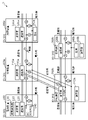
- FIG. 1 is a configuration diagram showing an example of a wiring system according to Embodiment 1.
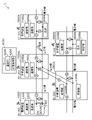
- FIG. FIG. 2 is a configuration diagram showing an example of a wiring system according to Embodiment 2.
- FIG. 3 is a configuration diagram showing an example of a wiring system according to Embodiment 3. As shown in FIG.
- each figure is a schematic diagram and is not necessarily strictly illustrated. Moreover, in each figure, the same code
- FIG. 1 is a configuration diagram showing an example of a wiring system 1 according to Embodiment 1. As shown in FIG.
- the wiring system 1 is a system comprising a power supply device 10 and one or more load devices connected by wiring.
- the wiring is, for example, the power line shown in FIG. It consists of a negative electrode side wiring connected to Wiring is provided on the ceiling, wall, floor, or the like of the facility.
- the wiring may further include a communication line.
- load devices 30a and 30b are shown as one or more load devices.
- the wiring system 1 may be provided with three or more load devices, and may be provided with one load device.
- the wiring system 1 further includes one or more branching devices for branching the wiring.
- branching devices 20a and 20b are shown as one or more branching devices.
- the wiring system 1 may be provided with three or more branching devices, and may be provided with one branching device.
- the wiring system 1 may include a plurality of power supply devices.
- the wiring in the wiring system 1 connects the power supply device 10 and the load devices 30a and 30b. By providing the wiring system 1 with the branching devices 20a and 20b, wiring can be arranged in a mesh pattern. Moreover, the wiring in the wiring system 1 may connect the power supply device 10 and a load device (not shown). Further, the wiring may be further branched by providing a branching device (not shown) in the wiring system 1 .
- the power supply device 10 is a device for supplying power to the load devices 30a and 30b.
- the power supply device 10 outputs DC power from a DC power supply 14 having a positive terminal and a negative terminal, and outputs DC power to the load devices 30a and 30b via positive wiring connected to the positive terminal and negative wiring connected to the negative terminal. Supply DC power.
- the load devices 30 a and 30 b are devices that consume power supplied from the power supply device 10 .
- the connection relationship between the elements to which power is supplied in the load devices 30a and 30b and the wiring is shown.
- Loads 34a and 34b schematically represent power-supplied elements in the load devices 30a and 30b, are connected between wiring and ground, and are supplied with DC power from the wiring.
- the load devices 30a and 30b are not particularly limited as long as they are devices that consume electric power, and are, for example, lighting fixtures.
- the branching devices 20a and 20b are devices for branching wiring.
- the branching device 20a provides a route connecting the branching device 20a and the power supply device 10, a route connecting the branching device 20a and the branching device 20b, and a route connecting the branching device 20a and the load device 30a.
- the branching device 20b provides a route connecting the branching device 20b and a load device (not shown) or a branching device, a route connecting the branching device 20b and the branching device 20a, and a route connecting the branching device 20b and the load device 30b. is provided.
- Each of the power supply device 10, the load devices 30a and 30b, and the branch devices 20a and 20b includes a measurement unit that measures the voltage and current in itself, and a communication unit that transmits or receives the measured voltage and current.
- the measuring unit measures the voltage and current by acquiring the voltage and current measured by, for example, a voltmeter and an ammeter. Although the measuring section, the voltmeter, and the ammeter are shown separately, the voltmeter and the ammeter themselves may be the measuring section.
- the communication unit is implemented by a communication interface or the like, and performs wired communication, for example.
- the power supply device 10 has a measurement unit 11 and a communication unit 12
- the branching device 20a has a measurement unit 21a and a communication unit 22a
- the branching device 20b has a measurement unit 21b and a communication unit 22b
- the load device 30a has a measurement unit 21b and a communication unit 22b.
- a unit 31a and a communication unit 32a are provided
- the load device 30b is provided with a measurement unit 31b and a communication unit 32b.
- the measurement unit 11 measures the voltage and current in the power supply device 10 . Specifically, the measurement unit 11 measures the output voltage and the output current from the power supply device 10 . More specifically, the measurement unit 11 measures the voltage between the positive electrode side wiring and the negative electrode side wiring that connect the branching device 20a and the power supply device 10, and the current flowing through the positive electrode side wiring or the negative electrode side wiring. Measure near the DC power supply 14 .
- the measuring unit 21a measures the voltage and current in the branching device 20a. Specifically, the measuring unit 21a measures the voltage between the positive electrode side wiring and the negative electrode side wiring near the branching point of the wiring by the branching device 20a. In addition, the measurement unit 21a measures the current flowing through the positive wire or the negative wire connecting the branch point and the power supply device 10, and the current flowing through the positive wire or the negative wire connecting the branch point and the branching device 20b. , and the current flowing through the positive electrode side wiring or the negative electrode side wiring connecting the branch point and the load device 30a is measured near the branch point.
- the measuring unit 21b measures the voltage and current in the branching device 20b. Specifically, the measuring unit 21b measures the voltage between the positive electrode side wiring and the negative electrode side wiring near the branching point of the wiring by the branching device 20b. In addition, the measurement unit 21b measures the current flowing through the positive-side wiring or the negative-side wiring connecting the branch point and the load device or branching device (not shown), the positive-side wiring or the negative electrode-side wiring connecting the branching point and the branching device 20a. A current flowing through the side wiring and a current flowing through the positive side wiring or the negative side wiring connecting the branch point and the load device 30b are measured near the branch point.
- the measurement unit 31a measures the voltage and current in the load device 30a. Specifically, the measuring unit 31a measures the voltage between the positive electrode side wiring and the negative electrode side wiring in the vicinity of the connection point between the wiring and the load 34a. In addition, the measuring unit 31a measures the current flowing through the positive wire or the negative wire connecting the connection point and the branching device 20a, the current flowing through the positive wire or the negative wire connecting the connection point and the load 34a, Then, the current flowing through the positive-side wiring or the negative-side wiring connecting the connection point and a load device or a branching device (not shown) is measured near the connection point.
- the measurement unit 31b measures the voltage and current in the load device 30b. Specifically, the measurement unit 31b measures the voltage between the positive wire and the negative wire near the connection point between the wire and the load 34b. In addition, the measurement unit 31b measures the current flowing through the positive wire or the negative wire connecting the connection point and the branching device 20b, the current flowing through the positive wire or the negative wire connecting the connection point and the load 34b, Then, the current flowing through the positive-side wiring or the negative-side wiring connecting the connection point and a load device or a branching device (not shown) is measured near the connection point.
- the respective communication units of the power supply device 10, the branch devices 20a and 20b, and the load devices 30a and 30b communicate with predetermined devices among the power supply device 10, the branch devices 20a and 20b, and the load devices 30a and 30b. conduct.
- a combination of devices that perform communication is an adjacent device. and the combination of the branch device 20b and the load device 30b.
- the communication unit 12 transmits the voltage and current measured by the measuring unit 11 to the branching device 20a, and receives the voltage and current measured by the measuring unit 21a from the branching device 20a.
- the communication unit 22a transmits the voltage and current measured by the measurement unit 21a to the power supply device 10, the branch device 20b, and the load device 30a, receives the voltage and current measured by the measurement unit 11 from the power supply device 10, and measures The voltage and current measured by the unit 21b are received from the branching device 20b, and the voltage and current measured by the measuring unit 31a are received from the load device 30a.
- the communication unit 22b transmits the voltage and current measured by the measuring unit 21b to the branching device 20a and the load device 30b, receives the voltage and current measured by the measuring unit 21a from the branching device 20a, and measures the voltage and current by the measuring unit 31b. Receive the applied voltage and current from the load device 30b.
- the communication unit 32a transmits the voltage and current measured by the measuring unit 31a to the branching device 20a, and receives the voltage and current measured by the measuring unit 21a from the branching device 20a.
- the communication unit 32b transmits the voltage and current measured by the measuring unit 31b to the branching device 20b, and receives the voltage and current measured by the measuring unit 21b from the branching device 20b.
- the wiring system 1 includes a state detection unit that detects the state of the wiring system 1 based on the measured voltage and current in each of the power supply device 10, the load devices 30a and 30b, and the branch devices 20a and 20b.
- the state of the wiring system 1 is, for example, the output power of the power supply device 10, the power consumption of the load devices 30a and 30b, the wiring abnormality, and the like.
- the state detection unit may be realized by a microcomputer (microcomputer).
- the microcomputer consists of a ROM (Read Only Memory) in which the program is stored, a RAM (Random Access Memory), a processor (CPU: Central Processing Unit) that executes the program, a communication interface, a timer, an A/D converter and a D/A conversion It is a semiconductor integrated circuit or the like having a device or the like.
- the state detection unit may be implemented in hardware by a dedicated electronic circuit or the like configured by an A/D converter, a logic circuit, a gate array, a D/A converter, and the like.
- the state detection unit detects an abnormality in the wiring system 1 based on the difference in voltage and current in each of the power supply device 10, the load devices 30a and 30b, and the branch devices 20a and 20b. For example, the state detection unit detects disconnection as an abnormality in the wiring system 1 based on the difference in voltage between the power supply device 10, the load devices 30a and 30b, and the branch devices 20a and 20b. Further, for example, the state detection unit detects an electric leakage as an abnormality in the wiring system 1 based on the difference in current between the power supply device 10, the load devices 30a and 30b, and the branch devices 20a and 20b.
- the state detection unit detects a short circuit in the wiring system 1 when the voltage in the power supply device 10 is not a specified value (eg, 24V, etc.).
- the state detection unit detects the sum of the power (output power) calculated from the voltage and current in the power supply device 10 and the power (power consumption) calculated from the voltage and current in each of the load devices 30a and 30b. An abnormality in the wiring system 1 is detected based on the difference between the .
- the state detection unit determines the state of each of the power supply device 10 and the load devices 30a and 30b, or the state of the power supply device 10, the load devices 30a and 30b, and the The state of wiring connecting each of the branching devices 20a and 20b is detected.
- each of the power supply device 10, the load devices 30a and 30b, and the branch devices 20a and 20b has a state detection unit.
- the power supply device 10 includes a state detection unit 13
- the branching device 20a includes a state detection unit 23a
- the branching device 20b includes a state detection unit 23b
- the load device 30a includes a state detection unit 33a
- the load device 30a includes a state detection unit 33a.
- the device 30b includes a state detection section 33b.
- the state detection unit 13 detects based on the voltage and current in the power supply device 10 measured by the measurement unit 11 and the voltage and current in the branch device 20a measured by the measurement unit 21a received by the communication unit 12. , the state of the power supply 10 and the state of the wiring connecting the power supply 10 and the branching device 20a.
- the state detection unit 23a detects based on the voltage and current in the branching device 20a measured by the measurement unit 21a and the voltage and current in the power supply device 10 measured by the measurement unit 11 received by the communication unit 22a. , the state of the power supply 10 and the state of the wiring connecting the power supply 10 and the branching device 20a. Further, for example, the state detection unit 23a detects the voltage and current in the branching device 20a measured by the measuring unit 21a and the voltage and current in the branching device 20b measured by the measuring unit 21b, which are received by the communication unit 22a. Based on this, the state of the wiring connecting the branching device 20a and the branching device 20b is detected.
- the state detection unit 23a detects the voltage and current in the branch device 20a measured by the measurement unit 21a and the voltage and current in the load device 30a measured by the measurement unit 31a, which are received by the communication unit 22a. Based on this, the state of the load device 30a and the state of the wiring connecting the branching device 20a and the load device 30a are detected.
- the state detection unit 23b detects the voltage and current in the branching device 20b measured by the measuring unit 21b, and the voltage and current in the branching device 20a measured by the measuring unit 21a, which are received by the communication unit 22b. , the state of the wiring connecting the branching device 20a and the branching device 20b. Further, for example, the state detection unit 23b detects the voltage and current in the branch device 20b measured by the measurement unit 21b and the voltage and current in the load device 30b measured by the measurement unit 31b, which are received by the communication unit 22b. Based on this, the state of the load device 30b and the state of the wiring connecting the branch device 20b and the load device 30b are detected.
- the state detection unit 33a detects the voltage and current in the load device 30a measured by the measurement unit 31a, and the voltage and current in the branch device 20a measured by the measurement unit 21a, which are received by the communication unit 32a. , the state of the load device 30a and the state of the wiring connecting the branch device 20a and the load device 30a.
- the state detection unit 33b is based on the voltage and current in the load device 30b measured by the measurement unit 31b and the voltage and current in the branch device 20b measured by the measurement unit 21b, which are received by the communication unit 32b. , the state of the load device 30b and the state of the wiring connecting the branch device 20b and the load device 30b.
- the state detection units 23a and 33a can detect that an electric leakage has occurred in the wiring connecting the branching device 20a and the load device 30a.
- the combination of the branching device 20a and the load device 30a that communicate with each other detects the leakage, it is possible to identify that the location where the leakage is occurring is the wiring that connects the branching device 20a and the load device 30a. can be done.
- each of the power supply device 10, the load devices 30a and 30b, and the branch devices 20a and 20b does not have to be equipped with a state detection unit.
- either one of the power supply device 10 and the branching device 20a may be provided with a state detection unit
- either one of the branching device 20a and the load device 30a may be provided with a state detection unit
- the branching device Either one of 20a and 20b may be provided with a state detection unit
- either one of branch device 20b and load device 30b may be provided with a state detection unit.
- the wiring system 1 is a system including the power supply device 10 and the load devices 30a and 30b connected by wiring.
- Each of the power supply device 10 and the load devices 30a and 30b includes a measurement unit that measures the voltage and current in itself, and a communication unit that transmits or receives the measured voltage and current.
- the wiring system 1 includes a state detection unit that detects the state of the wiring system 1 based on the measured voltage and current in the power supply device 10 and the load devices 30a and 30b.
- the wiring system 1 From the voltage and current measured by the power supply device 10 and the load devices 30a and 30b in the wiring system 1, the output power of the power supply device 10, the power consumption of the load devices 30a and 30b, the wiring abnormality, etc., the wiring system 1 can be detected.
- the state detection unit may detect an abnormality in the wiring system 1 based on the difference in voltage and current between the power supply device 10 and the load devices 30a and 30b. Specifically, the state detection unit may detect disconnection in the wiring system 1 based on the difference in voltage between the power supply device 10 and the load devices 30a and 30b. Moreover, the state detection unit may detect an electric leakage in the wiring system 1 based on a difference in current between the power supply device 10 and the load devices 30a and 30b.
- an abnormality in the wiring system 1 can be detected from the difference in voltage and current in each of the power supply device 10 and the load devices 30a and 30b.
- a wire breakage occurs in the wiring system 1
- a difference occurs between the voltage on the power supply device 10 side and the voltage on the opposite side of the power supply device 10 from the location where the wire breakage occurs. Disconnection in can be detected.
- an electric leakage occurs in the wiring system 1
- a difference occurs between the current on the side of the power supply device 10 from the location where the leakage has occurred and the current on the opposite side of the power supply device 10. Therefore, the electric leakage in the wiring system 1 can be detected.
- the state detection unit may detect a short circuit in the wiring system 1 when the voltage in the power supply device 10 is not a specified value.
- the state detection unit detects the power in the wiring system 1 based on the difference between the power calculated from the voltage and current in the power supply device 10 and the total power calculated from the voltage and current in each of the load devices 30a and 30b. Abnormalities may be detected.
- a difference may occur between the output power of the power supply device 10 and the total power consumption of the load devices 30a and 30b. can be done.
- the respective communication units of the power supply device 10 and the load devices 30a and 30b communicate with predetermined devices among the power supply device 10 and the load devices 30a and 30b, and the state detection units Based on the voltage and current for each combination, the state of each of the power supply device 10 and the load devices 30a and 30b, or the state of the wiring connecting the power supply device 10 and the load devices 30a and 30b may be detected.
- the state of the two devices in the combination and the state of the wiring connecting each of the two devices can be detected for each combination. For example, it is possible to identify the location where an abnormality has occurred.
- the wiring system 1 further includes branching devices 20a and 20b that branch the wiring, and each of the branching devices 20a and 20b communicates with a measurement unit that measures the voltage and current in itself and the measured voltage and current. and the state detection unit may detect the state of the wiring system 1 based on the voltage and current in each of the power supply device 10, the load devices 30a and 30b, and the branch devices 20a and 20b.
- FIG. 2 is a configuration diagram showing an example of the wiring system 2 according to the second embodiment.
- the wiring system 2 is a system comprising a power supply device 100 and one or more load devices connected by wiring.
- the wiring is, for example, the power line shown in FIG. It consists of a negative electrode side wiring connected to Wiring is provided on the ceiling, wall, floor, or the like of the facility.
- the wiring may further include a communication line.
- load devices 300a and 300b are shown as one or more load devices.
- the wiring system 2 may be provided with three or more load devices, and may be provided with one load device.
- the wiring system 2 further includes one or more branching devices for branching the wiring.
- branching devices 200a and 200b are shown as one or more branching devices.
- the wiring system 2 may be provided with three or more branching devices, and may be provided with one branching device.
- the wiring system 2 may include a plurality of power supply devices.
- the wiring in the wiring system 2 connects the power supply device 100 and the load devices 300a and 300b. Since the wiring system 2 includes the branching devices 200a and 200b, wiring can be arranged in a mesh pattern. Moreover, the power supply device 100 and a load device (not shown) may be connected by wiring in the wiring system 2 . Further, the wiring may be further branched by providing a branching device (not shown) in the wiring system 2 .
- the power supply device 100 is a device for supplying power to the load devices 300a and 300b.
- the power supply device 100 outputs DC power from a DC power supply 140 having a positive terminal and a negative terminal, and outputs DC power to the load devices 300a and 300b via positive wiring connected to the positive terminal and negative wiring connected to the negative terminal. Supply DC power.
- the load devices 300 a and 300 b are devices that consume power supplied from the power supply device 100 .
- the connection relationship between the elements to which power is supplied of the load devices 300a and 300b and the wiring is shown.
- Loads 340a and 340b schematically represent power-supplied elements in load devices 300a and 300b, are connected between wiring and ground, and are supplied with DC power from the wiring.
- the load devices 300a and 300b are not particularly limited as long as they are devices that consume power, and are, for example, lighting fixtures.
- the branching devices 200a and 200b are devices for branching wiring.
- the branching device 200a provides a route connecting the branching device 200a and the power supply device 100, a route connecting the branching device 200a and the branching device 200b, and a route connecting the branching device 200a and the load device 300a.
- the branching device 200b provides a route connecting the branching device 200b and a load device (not shown) or a branching device, a route connecting the branching device 200b and the branching device 200a, and a route connecting the branching device 200b and the load device 300b. is provided.
- Each of the power supply device 100, the load devices 300a and 300b, and the branch devices 200a and 200b includes a measurement unit that measures the voltage and current in itself, and a communication unit that transmits or receives the measured voltage and current.
- the measuring unit measures the voltage and current by acquiring the voltage and current measured by, for example, a voltmeter and an ammeter. Although the measuring section, the voltmeter, and the ammeter are shown separately, the voltmeter and the ammeter themselves may be the measuring section.
- the voltage and current measured by the measuring unit are associated with identification numbers as described later.
- the communication unit is implemented by a communication interface or the like, and performs wired communication, for example.
- the power supply device 100 includes a measurement unit 110 and a communication unit 120
- the branching device 200a includes a measurement unit 210a and a communication unit 220a
- the branching device 200b includes a measurement unit 210b and a communication unit 220b
- the load device 300a includes a measurement unit 210b and a communication unit 220b. It comprises a unit 310a and a communication unit 320a
- the load device 300b comprises a measurement unit 310b and a communication unit 320b.
- each of the power supply device 100, the load devices 300a and 300b, and the branch devices 200a and 200b is associated with an identification number for identifying each.
- ID: 001 is associated with the power supply device 100
- ID: 201 is associated with the branching device 200a
- ID: 202 is associated with the branching device 200b
- ID: 101 is associated with the load device 300a
- ID: 102 is associated with the load device 300b.
- the measurement unit 110 measures voltage and current in the power supply device 100 . Specifically, the measurement unit 110 measures the output voltage and the output current from the power supply device 100 . More specifically, the measurement unit 110 measures the voltage between the positive-side wiring and the negative-side wiring that connect the branching device 200a and the power supply device 100, and the current flowing through the positive-side wiring or the negative-side wiring. Measure near the DC power supply 140 . The voltage and current measured by the measurement unit 110 are associated with ID: 001, which is the identification number associated with the power supply device 100 .
- the measurement unit 210a measures the voltage and current in the branching device 200a. Specifically, the measuring unit 210a measures the voltage between the positive-side wiring and the negative-side wiring near the branching point of the wiring by the branching device 200a. In addition, the measurement unit 210a measures the current flowing through the positive-side wiring or the negative-side wiring connecting the branch point and the power supply device 100, the current flowing through the positive-side wiring or the negative-side wiring connecting the branching point and the branching device 200b. , and the current flowing through the positive electrode side wiring or the negative electrode side wiring connecting the branch point and the load device 300a is measured near the branch point.
- ID: 201 which is an identification number associated with the branching device 200a, is associated with the voltage and current measured by the measuring unit 210a. Since the currents are measured at three locations in the branching device 200a, the currents at the three locations may be associated with identification numbers that identify the currents at the three locations. For example, ID: 201A for the current measured by the left ammeter in FIG. 2, ID: 201B for the current measured by the lower ammeter in FIG. ID: 201C or the like is associated with the current.
- the measurement unit 210b measures the voltage and current in the branching device 200b. Specifically, the measurement unit 210b measures the voltage between the positive electrode side wiring and the negative electrode side wiring near the branch point of the wiring by the branching device 200b. In addition, the measurement unit 210b measures the current flowing through the positive-side wiring or the negative-side wiring connecting the branch point and a load device or branching device (not shown), the positive-side wiring or the negative electrode-side wiring connecting the branching point and the branching device 200a. A current flowing through the side wiring and a current flowing through the positive side wiring or the negative side wiring connecting the branch point and the load device 300b are measured near the branch point.
- ID: 202 which is an identification number associated with the branching device 200b, is associated with the voltage and current measured by the measuring unit 210b. Since the currents are measured at three locations in the branching device 200b, the currents at the three locations may be associated with identification numbers that identify the currents at the three locations. For example, ID: 202A for the current measured by the left ammeter in FIG. 2, ID: 202B for the current measured by the lower ammeter in FIG. ID: 202C or the like is associated with the current.
- the measurement unit 310a measures the voltage and current in the load device 300a. Specifically, the measuring unit 310a measures the voltage between the positive-side wiring and the negative-side wiring near the connection point between the wiring and the load 340a. In addition, the measurement unit 310a measures the current flowing through the positive wire or the negative wire connecting the connection point and the branching device 200a, the current flowing through the positive wire or the negative wire connecting the connection point and the load 340a, Then, the current flowing through the positive-side wiring or the negative-side wiring connecting the connection point and a load device or a branching device (not shown) is measured near the connection point. ID: 101, which is an identification number associated with the load device 300a, is associated with the voltage and current measured by the measuring unit 310a.
- the currents at the three locations may be associated with identification numbers that identify the currents at the three locations. For example, ID: 101A for the current measured by the left ammeter in FIG. 2, ID: 101B for the current measured by the lower ammeter in FIG. ID: 101C or the like is associated with the current.
- the measurement unit 310b measures the voltage and current in the load device 300b. Specifically, the measurement unit 310b measures the voltage between the positive-side wiring and the negative-side wiring near the connection point between the wiring and the load 340b. In addition, the measurement unit 310b measures the current flowing through the positive wire or the negative wire connecting the connection point and the branching device 200b, the current flowing through the positive wire or the negative wire connecting the connection point and the load 340b, Then, the current flowing through the positive-side wiring or the negative-side wiring connecting the connection point and a load device or a branching device (not shown) is measured near the connection point. ID: 102, which is an identification number associated with the load device 300b, is associated with the voltage and current measured by the measuring unit 310b.
- the identification number which identifies the current of three places may be string
- ID: 102A for the current measured by the left ammeter in FIG. 2 ID: 102B for the current measured by the lower ammeter in FIG. ID: 102C or the like is associated with the current.
- the communication unit 120 receives the voltage and current measured by the measuring unit 210a from the branching device 200a, receives the voltage and current measured by the measuring unit 210b from the branching device 200b, and calculates the voltage and current measured by the measuring unit 310a. Current is received from the load device 300a, and voltage and current measured by the measurement unit 310b are received from the load device 300b. Note that the communication unit 120 may transmit the voltage and current measured by the measurement unit 110 to other devices in the wiring system 2 .
- the communication unit 220a transmits the voltage and current measured by the measurement unit 210a to the power supply device 100. Note that the communication unit 220 a may transmit the voltage and current measured by the measurement unit 210 a to a device other than the power supply device 100 in the wiring system 2 . The communication unit 220a may also receive voltages and currents measured by other devices in the wiring system 2 .
- the communication unit 220b transmits the voltage and current measured by the measurement unit 210b to the power supply device 100. Note that the communication unit 220b may transmit the voltage and current measured by the measurement unit 210b to devices other than the power supply device 100 in the wiring system 2 . The communication unit 220b may also receive voltages and currents measured by other devices in the wiring system 2 .
- the communication unit 320a transmits the voltage and current measured by the measurement unit 310a to the power supply device 100. Note that the communication unit 320 a may transmit the voltage and current measured by the measurement unit 310 a to a device other than the power supply device 100 in the wiring system 2 . Also, the communication unit 320 a may receive voltage and current measured by other devices in the wiring system 2 .
- the communication unit 320b transmits the voltage and current measured by the measurement unit 310b to the power supply device 100. Note that the communication unit 320b may transmit the voltage and current measured by the measurement unit 310b to devices other than the power supply device 100 in the wiring system 2 . The communication unit 320b may also receive voltages and currents measured by other devices in the wiring system 2 .
- the wiring system 2 includes a state detection unit that detects the state of the wiring system 2 based on the measured voltage and current in each of the power supply device 100, the load devices 300a and 300b, and the branch devices 200a and 200b.
- the state of the wiring system 2 is, for example, the output power of the power supply device 100, the power consumption of the load devices 300a and 300b, the wiring abnormality, and the like.
- the state detection unit may be realized by a microcomputer (microcomputer).
- a microcomputer is a semiconductor integrated circuit or the like having ROM and RAM in which programs are stored, a processor (CPU) for executing programs, a communication interface, a timer, an A/D converter, a D/A converter, and the like.
- the state detection unit may be implemented in hardware by a dedicated electronic circuit or the like configured by an A/D converter, a logic circuit, a gate array, a D/A converter, and the like.
- the state detection unit detects an abnormality in the wiring system 2 based on the difference in voltage and current in each of the power supply device 100, the load devices 300a and 300b, and the branch devices 200a and 200b. For example, the state detection unit detects disconnection as an abnormality in the wiring system 2 based on the difference in voltage between the power supply device 100, the load devices 300a and 300b, and the branching devices 200a and 200b. Further, for example, the state detection unit detects an electric leakage as an abnormality in the wiring system 2 based on the difference in current between the power supply device 100, the load devices 300a and 300b, and the branching devices 200a and 200b.
- the state detection unit detects a short circuit in the wiring system 2 when the voltage in the power supply device 100 is not a specified value (eg, 24V, etc.).
- the state detection unit detects the sum of the power (output power) calculated from the voltage and current in the power supply device 100 and the power (power consumption) calculated from the voltage and current in each of the load devices 300a and 300b. An abnormality in the wiring system 2 is detected based on the difference between the .
- the state detection unit detects the states of the power supply device 100 and the load devices 300a and 300b based on the voltage, current, and identification number of each of the power source device 100, the load devices 300a and 300b, and the branch devices 200a and 200b. Alternatively, the state of wiring connecting the power supply device 100, the load devices 300a and 300b, and the branch devices 200a and 200b is detected.
- the power supply device 100 includes the state detection unit 130 .
- the state detection unit 130 detects the voltage and current in the power supply device 100 measured by the measurement unit 110, the voltage and current in the branch device 200a measured by the measurement unit 210a, and the voltage and current in the branch device 200a that are received by the communication unit 120. Based on the voltage and current in the branch device 200b measured by the measuring unit 310a and the voltage and current in the load device 300a measured by the measuring unit 310b, the wiring system 2 state is detected. Since the voltage and current associated with the identification number of each device in the wiring system 2 are collected in the power supply device 100, the state detection unit 130 detects the states of the power supply device 100, the load devices 300a and 300b, and each device. It can detect the state of the wiring to be connected.
- the state detection unit 130 detects the difference between the voltage received by the communication unit 120 and associated with ID: 101, which is the identification number of the load device 300a, and the voltage associated with the identification numbers of the other devices. , it can be detected that the wiring connecting the branching device 200a and the load device 300a is disconnected.
- branching devices 200a and 200b and the load device 300a or 300b may have a state detection unit.
- a device equipped with a state detection unit aggregates the voltage and current of each device in the wiring system 2 and detects the state in the wiring system 2 in the same way as when the power supply device 100 includes the state detection unit 130. may be detected.
- each of the power supply device 100 and the load devices 300a and 300b is associated with an identification number for identifying each. and the status of each of the power supply device 100 and the load devices 300a and 300b, or the wiring that connects each of the power supply device 100 and the load devices 300a and 300b based on the voltage and current and the identification number of each of the load devices 300a and 300b state is detected.
- FIG. 3 is a configuration diagram showing an example of the wiring system 3 according to the third embodiment.
- the wiring system 3 is a system comprising a power supply device 1000 and one or more load devices connected by wiring.
- the wiring is, for example, the power line shown in FIG. It consists of a negative electrode side wiring connected to Wiring is provided on the ceiling, wall, floor, or the like of the facility.
- load devices 3000a and 3000b are shown as one or more load devices.
- the wiring system 3 may be provided with three or more load devices, and may be provided with one load device.
- the wiring system 3 further includes one or more branching devices for branching the wiring.
- branching devices 2000a and 2000b are shown as one or more branching devices.
- the wiring system 3 may be provided with three or more branching devices, and may be provided with one branching device.
- the wiring system 3 may include a plurality of power supply devices.
- the wiring system 3 also includes a server 4000 capable of communicating with the communication units of the power supply device 1000, the load devices 3000a and 3000b, and the branch devices 2000a and 2000b.
- the wiring in the wiring system 3 connects the power supply device 1000 and the load devices 3000a and 3000b. By providing the wiring system 3 with the branching devices 2000a and 2000b, wiring can be arranged in a mesh pattern. Moreover, the power supply device 1000 and a load device (not shown) may be connected by wiring in the wiring system 3 . Further, the wiring may be further branched by providing a branching device (not shown) in the wiring system 3 .
- the power supply device 1000 is a device for supplying power to the load devices 3000a and 3000b.
- the power supply device 1000 outputs DC power from a DC power supply 1400 having a positive terminal and a negative terminal, and outputs DC power to load devices 3000a and 3000b via positive wiring connected to the positive terminal and negative wiring connected to the negative terminal. Supply DC power.
- the load devices 3000 a and 3000 b are devices that consume power supplied from the power supply device 1000 .
- the connection relationship between the elements to which power is supplied of the load devices 3000a and 3000b and the wiring is shown.
- Loads 3400a and 3400b are schematic representations of power-supplied elements in the load devices 3000a and 3000b, are connected between wiring and ground, and are supplied with DC power from the wiring.
- the load devices 3000a and 3000b are not particularly limited as long as they are devices that consume power, and are, for example, lighting fixtures.
- the branching devices 2000a and 2000b are devices for branching wiring.
- the branching device 2000a provides a route connecting the branching device 2000a and the power supply device 1000, a route connecting the branching device 2000a and the branching device 2000b, and a route connecting the branching device 2000a and the load device 3000a.
- the branching device 2000b provides a route connecting the branching device 2000b and a load device (not shown) or a branching device, a route connecting the branching device 2000b and the branching device 2000a, and a route connecting the branching device 2000b and the load device 3000b. is provided.
- Each of the power supply device 1000, the load devices 3000a and 3000b, and the branch devices 2000a and 2000b includes a measurement unit that measures the voltage and current in itself, and a communication unit that transmits or receives the measured voltage and current.
- the measuring unit measures the voltage and current by acquiring the voltage and current measured by, for example, a voltmeter and an ammeter. Although the measuring section, the voltmeter, and the ammeter are shown separately, the voltmeter and the ammeter themselves may be the measuring section.
- the voltage and current measured by the measuring unit are associated with identification numbers as described later.
- the communication unit is implemented by a communication interface or the like, and performs wireless communication, for example.
- the power supply device 1000 includes a measurement unit 1100 and a communication unit 1200
- the branching device 2000a includes a measurement unit 2100a and a communication unit 2200a
- the branching device 2000b includes a measurement unit 2100b and a communication unit 2200b
- the load device 3000a includes a measurement unit 2100b and a communication unit 2200b. It comprises a unit 3100a and a communication unit 3200a
- the load device 3000b comprises a measurement unit 3100b and a communication unit 3200b.
- each of the power supply device 1000, the load devices 3000a and 3000b, and the branch devices 2000a and 2000b is associated with an identification number for identifying each.
- ID: 001 is associated with the power supply device 1000
- ID: 201 is associated with the branching device 2000a
- ID: 202 is associated with the branching device 2000b
- ID: 101 is associated with the load device 3000a
- ID: 102 is associated with the load device 3000b.
- a measurement unit 1100 measures the voltage and current in the power supply device 1000 . Specifically, the measurement unit 1100 measures the output voltage and the output current from the power supply device 1000 . More specifically, the measurement unit 1100 measures the voltage between the positive electrode side wiring and the negative electrode side wiring that connect the branching device 2000a and the power supply device 1000, and the current flowing through the positive electrode side wiring or the negative electrode side wiring. Measure near the DC power supply 1400 . The voltage and current measured by the measuring unit 1100 are associated with ID:001, which is the identification number associated with the power supply device 1000 .
- the measurement unit 2100a measures the voltage and current in the branching device 2000a. Specifically, the measuring unit 2100a measures the voltage between the positive electrode side wiring and the negative electrode side wiring near the branch point of the wiring by the branching device 2000a. In addition, the measurement unit 2100a measures the current flowing through the positive wire or the negative wire connecting the branch point and the power supply device 1000, and the current flowing through the positive wire or the negative wire connecting the branch point and the branching device 2000b. , and the current flowing through the positive electrode side wiring or the negative electrode side wiring connecting the branch point and the load device 3000a is measured near the branch point. ID: 201, which is an identification number associated with the branching device 2000a, is associated with the voltage and current measured by the measuring unit 2100a.
- the currents at the three locations may be associated with identification numbers that identify the currents at the three locations. For example, ID: 201A for the current measured by the left ammeter in FIG. 3, ID: 201B for the current measured by the lower ammeter in FIG. ID: 201C or the like is associated with the current.
- the measurement unit 2100b measures the voltage and current in the branching device 2000b. Specifically, the measuring unit 2100b measures the voltage between the positive electrode side wiring and the negative electrode side wiring near the branching point of the wiring by the branching device 2000b. In addition, the measurement unit 2100b measures the current flowing through the positive-side wiring or the negative-side wiring connecting the branch point and a load device or branching device (not shown), the positive-side wiring or the negative electrode-side wiring connecting the branching point and the branching device 2000a. A current flowing through the side wiring and a current flowing through the positive side wiring or the negative side wiring connecting the branch point and the load device 3000b are measured near the branch point.
- ID: 202 which is an identification number associated with the branching device 2000b, is associated with the voltage and current measured by the measuring unit 2100b. Since the currents are measured at three locations in the branching device 2000b, the currents at the three locations may be associated with identification numbers that identify the currents at the three locations. For example, ID: 202A for the current measured by the left ammeter in FIG. 3, ID: 202B for the current measured by the lower ammeter in FIG. ID: 202C or the like is associated with the current.
- the measurement unit 3100a measures the voltage and current in the load device 3000a. Specifically, the measurement unit 3100a measures the voltage between the positive wire and the negative wire near the connection point between the wire and the load 3400a. In addition, the measurement unit 3100a measures the current flowing through the positive wire or the negative wire connecting the connection point and the branching device 2000a, the current flowing through the positive wire or the negative wire connecting the connection point and the load 3400a, Then, the current flowing through the positive-side wiring or the negative-side wiring connecting the connection point and a load device or a branching device (not shown) is measured near the connection point. ID: 101, which is an identification number associated with the load device 3000a, is associated with the voltage and current measured by the measuring unit 3100a.
- the identification number which identifies the current of three places may be tied
- the measurement unit 3100b measures the voltage and current in the load device 3000b. Specifically, the measurement unit 3100b measures the voltage between the positive wire and the negative wire near the connection point between the wire and the load 3400b. In addition, the measurement unit 3100b measures the current flowing through the positive wire or the negative wire connecting the connection point and the branching device 2000b, the current flowing through the positive wire or the negative wire connecting the connection point and the load 3400b, Then, the current flowing through the positive-side wiring or the negative-side wiring connecting the connection point and a load device or a branching device (not shown) is measured near the connection point. ID: 102, which is an identification number associated with the load device 3000b, is associated with the voltage and current measured by the measuring unit 3100b.
- the currents at the three locations may be associated with identification numbers that identify the currents at the three locations. For example, ID: 102A for the current measured by the left ammeter in FIG. 3, ID: 102B for the current measured by the lower ammeter in FIG. ID: 102C or the like is associated with the current.
- the communication unit 1200 transmits the voltage and current measured by the measurement unit 1100 to the server 4000.
- the communication unit 2200a transmits the voltage and current measured by the measurement unit 2100a to the server 4000.
- the communication unit 2200b transmits the voltage and current measured by the measurement unit 2100b to the server 4000.
- the communication unit 3200a transmits the voltage and current measured by the measurement unit 3100a to the server 4000.
- the communication unit 3200b transmits the voltage and current measured by the measurement unit 3100b to the server 4000.
- the server 4000 includes a communication unit 4200.
- the communication unit 4200 measures the voltage and current measured by the measurement unit 1100, the voltage and current measured by the measurement unit 2100a, the voltage and current measured by the measurement unit 2100b, and the voltage and current measured by the measurement unit 2100b. It receives the voltage and current measured at 3100a and the voltage and current measured at measuring section 3100b.
- the wiring system 3 includes a state detection unit that detects the state of the wiring system 3 based on the measured voltage and current in each of the power supply device 1000, the load devices 3000a and 3000b, and the branch devices 2000a and 2000b.
- the state of the wiring system 3 is, for example, the output power of the power supply device 1000, the power consumption of the load devices 3000a and 3000b, the wiring abnormality, and the like.
- the state detection unit detects an abnormality in the wiring system 3 based on the difference in voltage and current in each of the power supply device 1000, the load devices 3000a and 3000b, and the branch devices 2000a and 2000b. For example, the state detection unit detects disconnection as an abnormality in the wiring system 3 based on the voltage difference between the power supply device 1000, the load devices 3000a and 3000b, and the branch devices 2000a and 2000b. Further, for example, the state detection unit detects an electric leakage as an abnormality in the wiring system 3 based on the difference in current between the power supply device 1000, the load devices 3000a and 3000b, and the branching devices 2000a and 2000b.
- the state detection unit detects a short circuit in the wiring system 3 when the voltage in the power supply device 1000 is not a specified value (for example, 24V, etc.).
- the state detection unit detects the sum of the power (output power) calculated from the voltage and current in the power supply device 1000 and the power (power consumption) calculated from the voltage and current in each of the load devices 3000a and 3000b. An abnormality in the wiring system 3 is detected based on the difference between the .
- the state detection unit detects the respective states of the power supply device 1000 and the load devices 3000a and 3000b based on the voltage, current, and identification number of each of the power source device 1000, the load devices 3000a and 3000b, and the branch devices 2000a and 2000b.
- the state of wiring connecting the power supply device 1000, the load devices 3000a and 3000b, and the branch devices 2000a and 2000b is detected.
- the server 4000 includes a state detection unit 4300.
- State detection unit 4300 may be realized by a computer in the server.
- a computer has ROM and RAM in which programs are stored, a processor (CPU) for executing programs, a communication interface, and the like.
- the state detection unit 4300 receives the voltage and current in the power supply device 1000 measured by the measurement unit 1100, the voltage and current in the branching device 2000a measured by the measurement unit 2100a, and the voltage and current received by the measurement unit 2100b. Based on the measured voltage and current in the branch device 2000b, the voltage and current in the load device 3000a measured by the measuring unit 3100a, and the voltage and current in the load device 3000b measured by the measuring unit 3100b, the wiring system 3 Detect condition. Since the voltage and current associated with the identification number of each device in the wiring system 3 are aggregated in the server 4000, the state detection unit 4300 detects the state of the power supply device 1000, the load devices 3000a and 3000b, and the connection of each device. It is possible to detect the state of the wiring to be connected.
- the state detection unit 4300 detects that a short circuit has occurred in the wiring system 3 based on the voltage associated with ID: 001, which is the identification number of the power supply device 1000, received by the communication unit 4200. can do.
- the wiring system 3 includes the server 4000 capable of communicating with the communication units of the power supply device 1000 and the load devices 3000a and 3000b, and the server 4000 includes the state detection unit 4300. .
- the state of the wiring system 3 may be detected by the server 4000 .
- the wiring system 3 may not include the server 4000, and the power supply device 1000, the branch devices 2000a and 2000b, and the load device 3000a or 3000b may include state detection units.
- the device including the state detection unit receives and aggregates voltage and current wirelessly from other devices in the wiring system 3, A condition in system 3 may be sensed.
- the measurement unit measures the voltage and current in the device including the measurement unit, but the voltage and current in the device adjacent to the device including the measurement unit may also be measured.
- each device may not have a communication unit.
- the wiring system includes one or more branching devices, but the wiring system may not include branching devices.
- the wiring system may include an output unit that outputs the detection result of the state detection unit.
- the output unit outputs, for example, the detection result of the state detection unit to the administrator of the facility in which the wiring system is provided, the maintenance company of the wiring system, or the like.
Landscapes
- Physics & Mathematics (AREA)
- General Physics & Mathematics (AREA)
- Testing Of Short-Circuits, Discontinuities, Leakage, Or Incorrect Line Connections (AREA)
Priority Applications (1)
| Application Number | Priority Date | Filing Date | Title |
|---|---|---|---|
| JP2023522295A JPWO2022244486A1 (cg-RX-API-DMAC7.html) | 2021-05-21 | 2022-03-29 |
Applications Claiming Priority (2)
| Application Number | Priority Date | Filing Date | Title |
|---|---|---|---|
| JP2021086550 | 2021-05-21 | ||
| JP2021-086550 | 2021-05-21 |
Publications (1)
| Publication Number | Publication Date |
|---|---|
| WO2022244486A1 true WO2022244486A1 (ja) | 2022-11-24 |
Family
ID=84141235
Family Applications (1)
| Application Number | Title | Priority Date | Filing Date |
|---|---|---|---|
| PCT/JP2022/015402 Ceased WO2022244486A1 (ja) | 2021-05-21 | 2022-03-29 | 配線システム |
Country Status (2)
| Country | Link |
|---|---|
| JP (1) | JPWO2022244486A1 (cg-RX-API-DMAC7.html) |
| WO (1) | WO2022244486A1 (cg-RX-API-DMAC7.html) |
Citations (5)
| Publication number | Priority date | Publication date | Assignee | Title |
|---|---|---|---|---|
| JPH1022006A (ja) * | 1996-07-04 | 1998-01-23 | Yazaki Corp | インターフェイスコネクタ |
| JPH1068754A (ja) * | 1996-06-20 | 1998-03-10 | Yazaki Corp | 車両用電源供給装置及び該装置における異常検出装置 |
| JPH10271671A (ja) * | 1997-03-24 | 1998-10-09 | Furukawa Electric Co Ltd:The | 車両用給電装置 |
| JP2005082094A (ja) * | 2003-09-10 | 2005-03-31 | Taiheiyo Seiko Kk | 車両用ショート位置検出装置 |
| US20070279068A1 (en) * | 2006-05-31 | 2007-12-06 | Harres Daniel N | Power diagnostic system and method |
-
2022
- 2022-03-29 JP JP2023522295A patent/JPWO2022244486A1/ja active Pending
- 2022-03-29 WO PCT/JP2022/015402 patent/WO2022244486A1/ja not_active Ceased
Patent Citations (5)
| Publication number | Priority date | Publication date | Assignee | Title |
|---|---|---|---|---|
| JPH1068754A (ja) * | 1996-06-20 | 1998-03-10 | Yazaki Corp | 車両用電源供給装置及び該装置における異常検出装置 |
| JPH1022006A (ja) * | 1996-07-04 | 1998-01-23 | Yazaki Corp | インターフェイスコネクタ |
| JPH10271671A (ja) * | 1997-03-24 | 1998-10-09 | Furukawa Electric Co Ltd:The | 車両用給電装置 |
| JP2005082094A (ja) * | 2003-09-10 | 2005-03-31 | Taiheiyo Seiko Kk | 車両用ショート位置検出装置 |
| US20070279068A1 (en) * | 2006-05-31 | 2007-12-06 | Harres Daniel N | Power diagnostic system and method |
Also Published As
| Publication number | Publication date |
|---|---|
| JPWO2022244486A1 (cg-RX-API-DMAC7.html) | 2022-11-24 |
Similar Documents
| Publication | Publication Date | Title |
|---|---|---|
| US11442095B2 (en) | Cable harness test system and test method for checking cable harnesses | |
| US20150115741A1 (en) | Ac power over ethernet | |
| CN201532437U (zh) | 电缆查号核相器 | |
| JP2023081332A (ja) | 太陽電池モジュールの故障診断方法及び故障診断装置並びに故障検知装置 | |
| CN115812157A (zh) | 异常检测装置、异常检测方法以及程序 | |
| US20050271128A1 (en) | Distributed SCADA system for remote monitoring and control of access points utilizing an intelligent uninterruptible power supply system for a WISP network | |
| JP2014204545A (ja) | 電力計測装置及び電力計測システム | |
| US20130021037A1 (en) | Wireless portable battery capacity test system | |
| EP3577473A1 (en) | Elevator with a monitoring arrangement for monitoring an integrity of suspension members | |
| US11623844B2 (en) | Elevator with a monitoring arrangement for monitoring an integrity of suspension members with separated circuitries | |
| JP2013038917A (ja) | 故障診断装置、電力変換装置および故障診断方法 | |
| CN111157885A (zh) | 交直流通用继电器校验仪 | |
| WO2022044626A1 (ja) | アーク検出装置、アーク検出システム、アーク検出方法、及びプログラム | |
| JP7435800B2 (ja) | 直流配電システム、制御装置、異常検知方法、及びプログラム | |
| CN109313228B (zh) | 电气网络检查装置 | |
| CN104793094B (zh) | 用于电加热器的检测电路及方法、电加热系统 | |
| CN118399451A (zh) | 供电系统 | |
| FI99170C (fi) | Akun valvontajärjestelmä | |
| JP6012130B2 (ja) | クラスタ状態監視装置 | |
| JP6420622B2 (ja) | 太陽電池モジュールの状態を示す状態値を送受信するマネジメントユニット | |
| US8164216B2 (en) | Modular electrical system and method for its operation | |
| WO2024038989A1 (ko) | 다수의 콘센트에 연결된 부하의 누설상태를 측정하는 전기장치 및 그 방법. | |
| KR101582825B1 (ko) | 태양전지 모니터링장치 | |
| KR20250117060A (ko) | 태양광 발전모듈의 원격 단선 검출시스템 | |
| KR0139775Y1 (ko) | 연료펌프 및 계기 검사장치 |
Legal Events
| Date | Code | Title | Description |
|---|---|---|---|
| 121 | Ep: the epo has been informed by wipo that ep was designated in this application |
Ref document number: 22804403 Country of ref document: EP Kind code of ref document: A1 |
|
| WWE | Wipo information: entry into national phase |
Ref document number: 2023522295 Country of ref document: JP |
|
| NENP | Non-entry into the national phase |
Ref country code: DE |
|
| 122 | Ep: pct application non-entry in european phase |
Ref document number: 22804403 Country of ref document: EP Kind code of ref document: A1 |