WO2022244196A1 - 熱交換器 - Google Patents
熱交換器 Download PDFInfo
- Publication number
- WO2022244196A1 WO2022244196A1 PCT/JP2021/019184 JP2021019184W WO2022244196A1 WO 2022244196 A1 WO2022244196 A1 WO 2022244196A1 JP 2021019184 W JP2021019184 W JP 2021019184W WO 2022244196 A1 WO2022244196 A1 WO 2022244196A1
- Authority
- WO
- WIPO (PCT)
- Prior art keywords
- notch
- heat exchanger
- plate
- fin
- heat exchange
- Prior art date
- Legal status (The legal status is an assumption and is not a legal conclusion. Google has not performed a legal analysis and makes no representation as to the accuracy of the status listed.)
- Ceased
Links
Images






Classifications
-
- F—MECHANICAL ENGINEERING; LIGHTING; HEATING; WEAPONS; BLASTING
- F28—HEAT EXCHANGE IN GENERAL
- F28F—DETAILS OF HEAT-EXCHANGE AND HEAT-TRANSFER APPARATUS, OF GENERAL APPLICATION
- F28F1/00—Tubular elements; Assemblies of tubular elements
- F28F1/10—Tubular elements and assemblies thereof with means for increasing heat-transfer area, e.g. with fins, with projections, with recesses
- F28F1/12—Tubular elements and assemblies thereof with means for increasing heat-transfer area, e.g. with fins, with projections, with recesses the means being only outside the tubular element
- F28F1/24—Tubular elements and assemblies thereof with means for increasing heat-transfer area, e.g. with fins, with projections, with recesses the means being only outside the tubular element and extending transversely
- F28F1/32—Tubular elements and assemblies thereof with means for increasing heat-transfer area, e.g. with fins, with projections, with recesses the means being only outside the tubular element and extending transversely the means having portions engaging further tubular elements
Definitions
- the present disclosure relates to heat exchangers.
- a tapered notch is formed in the plate-like fin, and the cross-sectional shape of the flat heat exchange tube is fitted into the notch.
- a technique is disclosed in which flat heat exchange tubes are formed into a shape that fits, and flat heat exchange tubes are inserted into cutouts and brought into close contact with each other (see, for example, Patent Document 1).
- a heat exchanger includes a flat heat exchange tube, a fin into which the flat heat exchange tube is inserted, a notch into which the flat heat exchange tube is inserted, and a notch provided in the notch. , protrudes toward the inside of the cutout, contacts the flat heat exchange tube in a state in which the flat heat exchange tube is inserted into the cutout, and is inserted into the cutout of the flat heat exchange tube. and a holding portion that prevents movement in the opposite direction.
- the heat exchanger of the present disclosure is provided with holding portions protruding inward from cutout portions of the plate-shaped fins and having a short distance between them compared to the distance between the extending portions of the cutout portions. .
- FIG. 1 is a diagram showing the overall structure of a heat exchanger according to Embodiment 1;
- FIG. 4A and 4B are diagrams showing the structure of plate-like fins according to the first embodiment;
- FIG. 4 is a diagram showing a cross-sectional shape of a flat heat exchange tube in Embodiment 1.
- FIG. 4 is a diagram showing a process of inserting a flat heat exchange tube into a cutout portion of a plate-like fin in Embodiment 1.
- FIG. 4A and 4B are diagrams showing another structure of the plate-like fins according to Embodiment 1;
- FIG. FIG. 8 is a diagram showing still another structure of the plate-like fins according to Embodiment 1;
- FIG. 4 is a diagram showing a step of forming plate-like fins in Embodiment 1;
- FIG. 4 is a diagram showing a step of brazing in Embodiment 1;
- 8A and 8B are diagrams showing the structure of plate-like fins according to the second embodiment;
- FIG. 10 is a diagram showing a process of inserting a flat heat exchange tube into a cutout portion of a plate-like fin in Embodiment 2;
- FIG. 10 is a diagram showing the structure of plate-like fins according to Embodiment 3;
- FIG. 10 is a diagram showing a process of inserting a flat heat exchange tube into a cutout portion of a plate-like fin in Embodiment 3;
- FIG. 10 is a diagram showing a step of forming plate-like fins in Embodiment 3;
- FIG. 10 is a diagram showing the structure of plate-like fins according to Embodiment 4;
- FIG. 10 is a diagram showing a cross-sectional shape of a flat heat exchange tube in Embodiment 4;
- FIG. 12 is a diagram showing a process of inserting a flat heat exchange tube into a cutout portion of a plate-like fin in Embodiment 4;
- Embodiment 1 The configuration of the heat exchanger according to the present disclosure and the manufacturing method thereof will be described below.
- FIG. 1 is a diagram showing the overall configuration of a heat exchanger 100 according to the first embodiment.
- flat heat exchange tubes hereinafter referred to as flat tubes
- the flat tubes 50 are arranged parallel to each other at regular intervals.
- the plate-like fins 1 are also arranged parallel to each other at regular intervals.
- the plate-like fins 1 are arranged only on a part of the flat tube 50, but this is for the sake of representation of the figure, and in practice, the flat tube 50 does not exhibit its function. As many plate-like fins 1 as possible are arranged within a range that poses no problem.
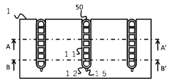
- FIGS. 2(a) to 2(c) are diagrams showing the structure of the plate-like fin 1 before the flat tube 50 is inserted.
- FIG. 2(a) is a view of the plate-like fin 1 as seen in a plane parallel to it
- FIG. 2(b) is a view of the plate-like fin 1 as seen from the side
- FIG. It is sectional drawing when cut
- the plate-like fin 1 has a plate-like shape and is provided with a plurality of cutouts 10 .
- Each notch 10 has the same shape and is provided at regular intervals in the longitudinal direction.
- the notch 10 is formed in a substantially U shape.
- the extending portion extending from the opening side of the U-shape is referred to as an extending portion 11, and the leading end portion of the notch portion 10 on the leading end side is referred to as a leading end portion 12.
- the tip portion 12 does not necessarily have to be curved, and may be linear. In that case, the tip portion 12 has a tapered shape composed of two straight lines.
- a holding portion 14 is provided at a part of the extending portion 11 as will be described later.
- a fin collar 13 is erected substantially perpendicularly to the thickness direction of the plate-like fin 1 from the peripheral portion of the notch portion 10 , that is, from the extension portion 11 and the tip portion 12 . That is, when viewed from a plane parallel to the plate-like fin 1 as shown in FIG. When the plate-like fin 1 is viewed from the side as shown in FIG. 2(b), the fin collar 13 with a height of about 1 [mm] to several mm extends uniformly in the depth direction of the notch 10. ing. A part of the fin collar 13 is omitted in FIG. 2(b) because a holding portion 14, which will be described later, is provided.
- a holding portion 14 is provided on a part of the extending portion 11. As shown in FIG.
- the holding portion 14 is a dome-shaped convex portion that protrudes toward the inside of the notch portion 10 . Comparing the cross section of the plate-like fin 1 along line AA' and line BB' shown in FIG. However, holding portions 14 are provided on the left and right sides of the notch portion 10 in the section BB'. Although the holding portion 14 is indicated by a thick line in the cross section B-B', this is for illustration purposes only and does not mean that the holding portion 14 is actually formed thick.
- the holding portion 14 is provided.
- the cross section BB' is narrower than the cross section AA'.
- the width of the cutout portion 10 at the cross section AA' is slightly larger than the width of the flat tube 50, which will be described later, and the notch at the cross section BB' where the holding portion 14 is provided.
- the width of the portion 10 is smaller than the width of the flattened tube 50 .
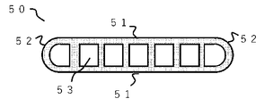
- FIG. 3 is a diagram showing the cross-sectional shape of the flat tube 50.
- the flat tube 50 is made of, for example, metal with high thermal conductivity such as aluminum, aluminum alloy, or copper.
- the outer shape of the flat tube 50 is composed of a flat portion 51 and a curved surface portion 52, and its cross-sectional shape is an approximately oval with semicircular ends.
- a flow path 53 through which a heat medium (refrigerant or the like) flows is formed inside the flat tube 50 .
- the shape of the channel 53 is not particularly limited, and may be circular, for example.
- a hairpin tube (not shown) that connects the flow paths 53 of the plurality of flat tubes 50 is attached to one end of the flat tube 50 (on the front side or the back side of the paper surface).
- the refrigerant that has flowed through the flow path 53 of a certain flat tube 50 from the front side of the paper surface to the back side turns back at the hairpin tube and flows through the flow path 53 of another flat tube 50 from the back side of the paper surface to the front side.
- a circular tube may be attached to one end of the flat tube 50 instead of the hairpin tube as long as the same function can be exhibited.
- a header pipe (not shown) is connected to the other end of the flat tube 50 .
- the header pipes have the function of evenly distributing the heat medium flowing into the heat exchanger 100 to the plurality of flat tubes 50 .
- the heat exchanger 100 may have a structure in which the hairpin tubes are not attached and header pipes are attached to both ends.
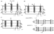
- FIGS. 4(a) to 4(d) are diagrams showing the process of inserting the flat tube 50 into the notch 10.
- FIG. 4(a), 4(b) and 4(c) are views viewed from a plane parallel to the plate-like fins 1, and FIGS. 4(a) and 4(b) show the flat tube 50.
- FIG. 4(c) shows a state in which the flat tube 50 is inserted into the notch 10.
- FIG. 4(d) is a cross-sectional view taken along line A-A' and line B-B' in FIG. 4(c).
- the flat tube 50 moves from the opening side of the notch 10 in the direction of the dashed arrow.
- the shape of the notch portion 10 of the plate-like fin 1 and the cross-sectional shape of the flat tube 50 are substantially the same, and the size of the notch portion 10 is slightly larger than the cross section of the flat tube 50 . More specifically, the distance between the extending portions 11 facing each other is greater than the width of the flat tube 50 (the distance between the flat portions 51 in the cross-sectional shape). Therefore, a slight gap is generated between the flat tube 50 and the notch 10 while the flat tube 50 is being inserted into the plate-like fin 1 as shown in FIG. Therefore, in the state shown in FIG. 4A, the flat tube 50 can be inserted with a small force.
- the flat portion 51 of the flat tube 50 reaches the holding portion 14 in the state shown in FIG. 4(b).
- the distance between the opposing holding portions 14 is shorter than the width of the flat tube 50 . Therefore, at the cross section B-B', the holding portion 14 and the flattened portion 51 of the flattened tube 50 come into contact with each other as shown in FIG. 4(d).
- the holding portion 14 and the flat portion 51 are in line contact because the holding portion 14 is shaped like a small convex portion. Therefore, even in the state shown in FIG. 4(b), the flat tube 50 can be inserted with a minimum force.
- FIG. 4(d) shows the state of the section A-A', in which the fin collars 13 support the flattened tube 50 from the left and right sides. Thereby, the flat tube 50 can be kept substantially perpendicular to the plate-like fins 1 .
- the configuration described above is the minimum configuration for exhibiting the functions of the heat exchanger 100 in the present disclosure, and the heat exchanger 100 can be variously modified within the scope of the present disclosure.
- the position of the holding part 14 is not limited to the positions shown in FIGS. 2 and 4, and can be any position. However, it is desirable that the retainer 14 be located closer to the distal end 12 than half of the extension 11 . This is because when the holding portion 14 is provided on the far side of the extension portion 11, the timing of contact between the holding portion 14 and the flat tube 50 when the flat tube 50 is inserted into the notch portion 10 can be delayed, and the flat tube 50 can be made small. This is because the range that can be inserted by force increases.
- the flat tube 50 may drop out of the notch portion 10 after being inserted into the notch portion 10 .
- the holding portion 14 is located right next to the tip portion 12, even if the flat tube 50 is slightly displaced toward the opening of the notch portion 10 when the flat tube 50 is inserted into the notch portion 10, There is a possibility that the contact between the holding portion 14 and the flat tube 50 becomes weak and the flat tube 50 falls out of the notch portion 10 .
- the holding portion 14 be located on the inner side of the half of the notch portion 10 and away from the tip portion 12 .
- the plate-like fin 1 may be provided with a plurality of spacing tabs.
- the spacing tabs have the function of keeping the intervals between the plate-like fins 1 when the flat tubes 50 are inserted into the plate-like fins 1 .
- 5(a) and 5(b) are diagrams showing the structure of the plate-like fin 1 when the spacing tab 16 is provided. As shown in FIG. 5(a), spacing tabs 16 of the same shape are provided on the plate-like fin 1 at predetermined intervals.
- FIG. 5(b) is a cross-sectional view of the plate-like fin 1 along the line A-A' in a state where the plate-like fin 1 is combined with the flat tube 50.
- each spacing tab 16 is erected vertically with respect to the plate-like fin 1, and has a hook-like shape in which the tip is bent at right angles.
- the spacing tabs 16 provided on one plate-like fin 1 are in contact with the adjacent plate-like fins 1 . More specifically, the bent tip portion of the spacing tab 16 comes into surface contact with the adjacent plate-like fins 1 and maintains the interval between the two plate-like fins 1 . Thereby, the intervals between the plurality of plate-like fins 1 are kept constant, and the performance of the heat exchanger 100 is improved.
- the plate-like fin 1 may be provided with a turbulence promoting portion such as a cut-and-raise.
- the turbulence promoting section generates turbulence in the airflow supplied to the heat exchanger 100 to promote heat exchange between the air and the plate-like fins 1 .
- the turbulent flow is basically promoted by providing unevenness on the plate-like fin 1, and specific shapes of the turbulence-promoting portion include rectangular unevenness, triangular fins perpendicular to the plate-like fin 1, and plate-like fin 1.
- a hole passing through the Any number of turbulence promoting portions may be formed on the plate-like fin 1 at appropriate intervals.
- the plate-like fin 1 may be a so-called clad fin having a brazing material applied to its surface.
- the heat exchanger 100 is put into a heating device such as an electric furnace.
- the applied brazing material melts due to the heat and flows on the surfaces of the plate-like fins 1 .
- the brazing material flows into the gap between the flat tube 50 and the plate-like fin 1 and the vicinity of the contact portion between the flat tube 50 and the plate-like fin 1 .
- the brazing material solidifies, and the brazing material functions as an adhesive that bonds the plate-like fins 1 and the flat tubes 50 together. Thereby, the plate-like fin 1 and the flat tube 50 can be firmly adhered. Moreover, since the gap between the plate-like fins 1 and the flat tubes 50 is filled with brazing material, the performance of the heat exchanger 100 is also improved.
- the brazing material may be applied to both the front and back surfaces of the plate-like fin 1, or either one of them, centering on the tip portion 12 side of the notch portion 10.
- the brazing material may be applied along the notch 10 of the plate-like fin 1 and the fin collar 13 .
- the amount and range of application of the brazing material may be appropriately set according to the size and shape of the plate-like fins 1 and the flat tubes 50 .
- FIG. 6 is a diagram showing the structure of the plate-like fin 1 when the guiding portion 15 is provided.
- the guiding portion 15 has a function of guiding the brazing material to flow into an appropriate position in the brazing process. Specifically, when the brazing material begins to melt, the brazing material flows into the guide portion 15 and fills the space between the notch portion 10 and the fin collar 13 and the flat tube 50 as it is. As a result, the plate-like fins 1 and the flat tubes 50 are brazed more firmly.
- the plate-like fins 1 are explained as clad fins.
- a metal plate coated with brazing material which is the material of the plate-like fins 1, is notched or pressed to form a notch (step 1).
- the notch at this time has a shape similar to that of the notch 10 , but is smaller in size than the notch 10 .
- the said small notch part is described with a "temporary notch part.”
- FIG. 7(a) and 7(b) are diagrams showing an example of a method for processing a metal plate in step 1.
- FIG. FIG. 7(a) is a state of processing including the entire temporary notch portion
- FIG. 7(b) is an enlarged view of the circle shown in FIG. 7(a).
- 7(a) and 7(b) also show a brazing material used in a later step.
- the temporary notch portion is shaded, and the notch portion 10 to be formed in a later step is indicated by a chain line.
- the temporary notch is smaller than the notch 10 .
- a portion between the temporary notch portion and the extended portion 11 of the notch portion 10 and a portion between the temporary notch portion and the tip portion 12 of the notch portion 10 are provided upright in a later step to form a fin collar 13 . Therefore, it is desirable to set the distance between the temporary notch and the notch 10 to about several millimeters.
- the holding portion 14 may be formed into a completed shape in step 1. This is because the fin collar 13 is not provided in the portion corresponding to the holding portion 14 in a later process.
- the portion between the temporary notch portion and the notch portion 10 is bent, and the portion is erected vertically on the plate-like fin 1 to form the fin collar 13 (step 2).
- the notch is enlarged by erecting the peripheral edge portion of the temporary notch portion, and the notch portion 10 is formed.
- the plate-like fin 1 is completed.
- the spacing tabs 16, the turbulent flow promotion part, and the guide part 15 on the plate-like fin 1 are formed by carrying out necessary processing according to a processing method according to the purpose.
- a plurality of plate-shaped fins 1 formed as described above are fixed to the device so that the opening side of the notch 10 is vertically upward, and the flat tube 50 is inserted (step 3).
- the holding part 14 sandwiches the flat part 51 of the flat tube 50 from both sides and holds the positional relationship between the flat tube 50 and the plate-like fin 1 . function.
- the flat tube 50 may be fixed and the plate-like fins 1 may be moved and assembled.
- the plate-like fins 1 in which the flat tubes 50 are inserted in this manner are hereinafter referred to as "temporarily assembled heat exchangers".
- the position of the temporarily assembled heat exchanger is changed so that the opening side of the notch 10 is vertically downward (step 4).
- the attitude of the temporarily assembled heat exchanger may be changed manually or by a device. Regardless of which method is used, the positional relationship between the flat tube 50 and the plate-like fins 1 is held by the holding portion 14, so the flat tube 50 may drop off from the plate-like fins 1 or become misaligned. Few fears.
- the temporarily assembled heat exchanger is put into a heating device such as an electric furnace while maintaining the posture described above.
- a heating device such as an electric furnace
- the brazing material applied to the plate-like fins 1 melts (step 5).
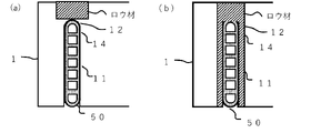
- 8(a) and 8(b) are diagrams showing the state of the brazing filler metal before and after heating.
- the brazing material applied to the tip portion 12 side of the plate-like fin 1 melts by heating and flows vertically downward along the plate-like fin 1, that is, to the opening side of the notch portion 10.
- FIG. 8(a) the brazing material applied to the tip portion 12 side of the plate-like fin 1 melts by heating and flows vertically downward along the plate-like fin 1, that is, to the opening side of the notch portion 10.
- the brazing material that has flowed out fills the gaps between the notch 10 and the fin collar 13 and the flat tube 50 as shown in FIG. 8(b). In this manner, the plate-like fin 1 and the flat tube 50 are brazed.
- the flat portion 50 and the fin collar 13 are bonded to each other via the wax as described above, if the height of the fin collar 13 is uniform, the bonding surface between the flat tube 50 and the fin collar 13 is stretched. Since it is generated widely in the direction of the portion 11 without deviation, the possibility that the brazing material will be destroyed and the adhesion will be weakened when a force is applied to the flat tube 50 is reduced.
- the temporarily assembled heat exchanger is removed from the heating device and cooled (step 6).
- the cooling method is not limited, but it is desirable to cool from the opening side of the notch 10 .
- the brazing filler metal on the opening side of the notch portion 10 solidifies first among the melted brazing filler metals, and then the brazing filler metal solidifies upward from the opening side.
- the brazing material is less likely to drop from the plate-like fins 1, so that the plate-like fins 1 and the flat tubes 50 are strongly bonded together, and the performance of the completed heat exchanger 100 is improved.
- the heat exchanger 100 is manufactured through the above steps.
- the heat exchanger 100 described above has the following effects.
- the flat tube 50 is inserted into the cutout portion 10 of the plate-like fin 1, only the holding portion 14 contacts the flat tube 50, so the flat tube 50 can be inserted with a small force.
- the holding part 14 contacts the flat part 51 of the flat tube 50 to hold the positional relationship between the plate-like fin 1 and the flat tube 50 .
- the flat tubes 50 are less likely to come off from the plate-like fins 1 or become misaligned.
- the holding portion 14 holds the flattened portion 51 of the flattened tube 50 inserted into the notch portion 10 so as to sandwich the flattened portion 51 from the left and right sides. Therefore, the holding portion 14 does not limit the dimension of the flat tube 50 in the insertion direction of the flat tube 50 into the notch portion 10 . Therefore, the plate-like fins 1 having the same shape can be applied to a plurality of types of flat tubes 50 having different lengths, and the degree of freedom in design can be ensured at low cost.
- the distance between the opposing holding portions 14 is shorter than the width of the flat tube 50 .
- the springiness of the metal material acts on the flat tube 50 inserted into the notch 10 . This increases the likelihood that the flattened tube 50 can be positioned accurately at the designed position.
- the plate-like fin 1 is made of a metal material such as aluminum, aluminum alloy, copper, etc., but a spring material standardized by JIS (Japanese In Industrial Standards) or the like may be used as the material.
- JIS Japanese In Industrial Standards
- a spring material for the plate-like fins 1 the force exerted by the holding portion 14 is increased, and the possibility of the flat tubes 50 dropping off from the plate-like fins 1 or being displaced can be reduced.
- the holding portion 14 of the plate-like fin 1, which is a technical feature of the heat exchanger 100, may not be visible from the outside because it is covered with brazing material after brazing. . Therefore, in order to confirm that the holding portion 14 is provided, it is necessary to heat and melt the wax. The presence of the holding portion 14 can be confirmed by melting the brazing material.
- the holding portion 14 may be deformed by the insertion of the flat tube 50, making it difficult to confirm.
- the fin collar 13 which often has a uniform height in the direction perpendicular to the plate-like fins 1, is intentionally made partly of the fin collar 13.
- the omission includes the possibility that the heat exchanger 100 has the technical features of the present embodiment.
- the present invention can be confirmed. It can be determined whether the heat exchanger 100 has the technical features of the embodiment.
- Embodiment 2 of the present disclosure will be described with reference to FIGS. 9 and 10.
- FIG. The configuration of the heat exchanger 100a of the present embodiment is substantially the same as that of the heat exchanger 100 of the first embodiment, but the shape of the plate-like fins and the functions exhibited are different.
- the heat exchanger 100a according to the present embodiment will be described below, focusing on differences from the first embodiment.
- the parts whose description is omitted are the same as those in the first embodiment.
- FIGS. 9(a) to 9(c) are diagrams showing the shape of the plate-like fins 1a in the present embodiment.
- Fig. 9(a) is a view of a plane parallel to the plate-like fin 1a
- Fig. 9(b) is a view of the plate-like fin 1a as seen from the side
- Fig. 9(c) is a view of the plate-like fin 1a cut away. It is a cross-sectional view taken along the opening of the cutout 10a and the line CC'.
- the notch portion 10a of the plate-like fin 1a in this embodiment is common to the plate-like fin 1 of the first embodiment in that it has an extending portion 11 and a tip portion 12.
- the holding portion 14a of the plate-like fin 1a is provided in the opening of the notch portion 10a, and is positioned differently from the holding portion 14 of the plate-like fin 1.
- the size of the holding portion 14a can be determined arbitrarily.
- the shape of the holding portion 14a is desirably a shape having a curved portion.
- the shape of the holding portion 14a is desirably a semicircular shape shown in FIG. 9 or FIG. 10 described later.
- the curved portion of the holding portion 14a contacts the curved surface portion 52 of the flat tube 50 inserted into the notch portion 10a as will be described later.
- FIG. 9(b) is a side view of the plate-like fin 1a.
- fin collars 13 are erected substantially vertically from the peripheral edge portions of the extended portion 11 and the tip portion 12 .
- the height of the fin collar 13 is not particularly limited in the present embodiment, and is about 1 [mm] to several mm.
- FIG. 9(c) is a sectional view of the plate-like fin 1a when the plate-like fin 1a is cut along the opening of the notch portion 10a and the line C-C'.
- the holding portion 14a is provided in the opening of the notch 10a, and the width of the opening of the notch 10a is small.
- the extending portions 11 are not provided with the holding portions 14a, so the distance between the extending portions 11 facing each other is large.
- FIGS. 10(a) to 10(e) are diagrams when the flat tube 50 is inserted into the notch portion 10a.
- 10(a) and 10(b) are views viewed from a plane parallel to the plate-like fins 1a
- FIG. 10(a) is a view during insertion of the flat tube 50 into the notch 10a
- 10(b) is a diagram showing a state in which the flat tube 50 is inserted into the notch portion 10a.
- Line C-C' in FIGS. 10(a) and 10(b) is at the same position as line C-C' shown in FIG. 9(a).
- 10(c) and 10(d) are enlarged views of the opening of the notch 10a during and after the flat tube 50 is being inserted into the notch 10a.
- FIG. 10(e) is a cross-sectional view of the plate-like fin 1a along the line C-C' in a state where the flattened tube 50 is inserted into the notch portion 10a.
- the flat tube 50 moves in the direction of the dashed arrow from the opening side of the notch 10a.
- the holding portions 14 a are provided at the openings of the notch portions 10 a , and the distance between the holding portions 14 a facing each other is smaller than the width of the flat tube 50 . Therefore, when the flat tube 50 is inserted into the notch portion 10a, the flat tube 50 comes into contact with the holding portion 14a and expands the notch portion 10a outward as shown in FIG. 10(c). Since the holding portion 14a has a uniform shape in the thickness direction of the plate-like fin 1a, the holding portion 14a and the flat tube 50 are in line contact.
- FIG. 10(b) is a diagram showing a state in which the flat tube 50 is inserted into the notch portion 10a. At this time, at the opening of the notch 10a, as shown in FIG. In this state, the flat tube 50 is caught by the holding portion 14a even if the opening of the notch portion 10a is directed vertically downward, for example. Therefore, there is little concern that the flat tube 50 will be misaligned or that the flat tube 50 will drop out of the notch 10a.
- the cross-sectional shape of the flat tube 50 and the shape of the notch portion 10a are substantially the same. Further, in the plate-like fin 1a, the flat portion 51 of the flat tube 50 and the holding portion 14a do not come into contact with each other in the state shown in FIG. 10(b). Therefore, in the present embodiment, the distance between the extending portions 11 facing each other and the width of the flat tube 50 can be substantially matched, and as shown in FIG. The gap between them becomes smaller. At the same time, since the contact area of the fin collar 13 with the flat tube 50 is large, the role of the fin collar 13 that defines the position of the flat tube 50 is more strongly exhibited.
- the position of the holding portion 14a in the present embodiment is not limited to the positions shown in FIGS. Specifically, the holding portion 14a may be arranged at a position where the curved portion contacts the curved surface portion 52 of the flat tube 50 when the flat tube 50 is inserted into the notch portion 10a. Therefore, the holding portion 14a may be arranged at a position slightly inside the notch portion 10a from the end portion of the notch portion 10a other than the end portion of the notch portion 10a.
- the holding portion 14a When the holding portion 14a is arranged at the end of the notch portion 10a, and when the holding portion 14a is arranged at a position slightly inside the notch portion 10a from the end portion of the notch portion 10. and each have their own advantages.
- the holding portion 14a when the holding portion 14a is arranged at the end of the notch portion 10a, when the flat tube 50 is inserted into the notch portion 10a, the holding portion 14a is held so as to wrap the curved surface portion 52 of the flat tube 50. Therefore, the flat tube 50 is less likely to come off from the notch 10a.
- the holding portion 14a when the holding portion 14a is arranged at a position slightly inside the cutout portion 10a from the end portion of the cutout portion 10, the width of the opening of the cutout portion 10a becomes large. It becomes easy to align when inserting the flat tube 50 into the notch 10a, and it becomes easy to insert the flat tube 50 into the notch 10a.
- the holding portion 14a may be positioned at a position where the curved portion of the holding portion 14a and the curved surface portion 52 of the flat tube 50 come into contact when the flat tube 50 is inserted into the notch portion 10a.
- a more detailed position of the holding part 14a can be determined by the designer according to each advantage.
- a metal plate coated with brazing material which is the material of the plate-like fins 1a, is formed with a temporary notch by notching or pressing (step 1).
- the temporary notch portion is similar in shape to the notch portion 10a, but is smaller in size than the notch portion 10a.
- the holding portion 14a can be formed at the same time. Specifically, in the same manner as in the first embodiment, the portion where the fin collar 13 is not provided in the post-process is molded into the final shape in the first process.
- the fin collar 13 is formed by bending along the peripheral edge of the temporary notch (step 2).
- the temporary notch portion is enlarged to form the notch portion 10a.
- the plate-like fin 1 is completed.
- a plurality of plate-like fins 1a formed as described above are fixed to the device so that the opening side of the notch 10a is vertically upward, and the flat tube 50 is inserted (step 3).
- the tip of the flat portion 51 reaches the holding portion 14a provided at the opening of the plate-like fin 1a, the flat tube 50 comes into contact with the holding portion 14a and spreads the notch portion 10a outward, and the notch portion 10a It is inserted deep inside.
- the holding portion 14a is in contact with the curved surface portion 52 of the flat tube 50 to hold the flat tube 50, thereby holding the position of the flat tube 50. Demonstrate. Thus, the heat exchanger 100a is temporarily assembled.
- the temporarily assembled heat exchanger is placed so that the opening side of the notch portion 10a faces vertically downward (step 4).
- the holding portion 14a holds the curved surface portion 52 of the flat tube 50, there is little possibility that the flat tube 50 will drop off from the plate-like fin 1a or be displaced.
- the temporarily assembled heat exchanger is put into a heating device such as an electric furnace while maintaining the above posture and brazed (step 5).
- the brazing material applied to the tip portion 12 side of the notch portion 10a melts by heating and flows out to the opening side of the notch portion 10a.
- the brazed and temporarily assembled heat exchanger is removed from the heating device and cooled (step 6). Through the above steps, the heat exchanger 100a is manufactured.
- the heat exchanger 100a described above has the following effects in addition to the effects of the heat exchanger 100 in the first embodiment. After the flat tube 50 is inserted into the plate-like fins 1 a , the holding portion 14 a contacts only the curved surface portion 52 of the flat tube 50 . Therefore, the gap between the notch portion 10a and the flat tube 50 is reduced, and the heat transfer performance of the heat exchanger 100a can be improved.
- the presence of the holding portion 14a which is a technical feature of the heat exchanger 100a in this embodiment, is confirmed by the same method as in the first embodiment. That is, it is possible to determine whether or not it is the heat exchanger 100a by visual inspection after melting the wax, partial missing of the fin collar 13, evidence of scratching of the flat portion 51, and the like.
- Embodiment 3 A third embodiment of the present disclosure will be described with reference to FIGS. 11 to 13.
- FIG. The configuration of the heat exchanger 100b of the present embodiment is substantially the same as the heat exchanger 100 of the first embodiment and the heat exchanger 100a of the second embodiment, but the shape and function of the plate-like fins are different. different.
- the heat exchanger 100b according to the present embodiment will be described below, focusing on differences from the first and second embodiments.
- the configurations whose description is omitted are the same as those of the first and second embodiments.
- FIGS. 11(a) to 11(c) are diagrams showing the shape of the plate-like fins 1b in the present embodiment.
- FIG. 11(a) is a view of the plate-like fin 1b as seen in a plane parallel to it
- FIG. 11(b) is a view of the plate-like fin 1b as seen from the side
- FIG. It is sectional drawing when cut
- the notch portion 10 b of the plate-like fin 1 b in the present embodiment has the extended portion 11 and the tip portion 12 , which is different from that of the plate-like fins 1 and 2 of the first and second embodiments.
- the first embodiment is characterized in that the fin collars erected from the entire extended portion 11 are not substantially perpendicular to the extended portion 11, but are provided so that their tips are inclined toward the inner side of the notch portion 10b. , 2.
- the tip of the fin collar means the portion on the side opposite to the extended portion 11 .
- the fin collar in the present embodiment exhibits the function of holding the flat tube 50 inserted into the notch portion 10b. Therefore, hereinafter, the fin collar erected from the extending portion 11 is described as a holding portion 14b assuming that it is integrated with the holding portion.
- the fin collar 13 erected from the tip portion 12 is erected substantially perpendicularly to the tip portion 12 as in the first and second embodiments.
- FIG. 11(b) is a side view of the plate-like fin 1b.
- the holding portion 14b erected from the extending portion 11 is inclined such that the tip thereof faces the inside of the notch portion 10b.
- the fin collar 13 erected from the tip portion 12 is substantially perpendicular to the tip portion 12 . Therefore, when the flat tube 50 is not inserted into the notch portion 10b, the apparent heights of the holding portion 14b and the fin collar 13 may differ. It should be noted that this does not limit the relationship between the holding portion 14b and the fin collar 13, and the height of each can be determined independently and arbitrarily.
- FIG. 11(c) is a cross-sectional view of the plate-like fin 1b taken along line D-D' and line E-E'.
- the tip of the holding portion 14b faces the inside of the notch portion 10b. Therefore, as shown in FIG. 11(c), the width between the tips of the holding portions 14b is narrower than the width between the roots of the holding portions 14b. As will be described later, the width between the tips of the holding portion 14b is narrower than the width of the flat tube 50, and the width between the bases of the holding portion 14b is larger than the width of the flat tube 50.
- FIGS. 12(a) to 12(c) are diagrams when the flat tube 50 is inserted into the notch portion 10b.
- 12(a) and 12(b) are views viewed from a plane parallel to the plate-like fin 1b
- FIG. 12(a) is a view during insertion of the flat tube 50 into the notch 10b
- 12(b) is a diagram showing a state in which the flat tube 50 is inserted into the notch portion 10b.
- Lines D-D' and E-E' are lines at the same positions as the lines D-D' and E-E' shown in FIG. 11(a).
- FIG. 12(c) is a sectional view of the plate-like fin 1b taken along the line D-D' before and after the flat tube 50 is inserted into the notch 10b.
- the flat tube 50 moves in the direction of the dashed arrow from the opening side of the notch 10b.
- the holding portion 14b is erected from the extending portion 11, and the width between the tips of the holding portion 14b is narrower than the width of the flat tube 50.
- the flat portion 51 comes into contact with the holding portion 14b and is inserted while expanding the holding portion 14b.
- FIG. 12(c) shows changes in the holding portion 14b before and after the flat tube 50 is inserted into the notch portion 10b.
- the holding part 14b Before the flat tube 50 is inserted, the holding part 14b is inclined and the width between the tips thereof is smaller than the width of the flat tube 50 .
- the holding portion 14 b is expanded by the flat tube 50 and becomes substantially perpendicular to the extending portion 11 .
- the holding portion 14b is in contact with the flat portion 51 and holds the flat tube 50 by sandwiching it from the left and right. Therefore, at this time, even if the opening of the notch portion 10b is directed vertically downward, the risk of the flat tube 50 being displaced or falling off from the notch portion 10b is reduced.
- a metal plate coated with brazing material which is the material of the plate-like fins 1b, is formed with a temporary notch by notching or pressing (step 1).
- 13(a) and 13(b) are diagrams showing an example of a method for processing a metal plate in step 1.
- FIG. The temporary notch portion is similar in shape to the notch portion 10b, but is smaller in size than the notch portion 10b.
- step 1 a cut is made at the boundary between the extended portion 11 and the tip portion 12 of the notch portion 10b formed in the next step. This is because the holding portion 14b and the fin collar 13 erected from the tip portion 12 are separately molded in the next step.
- FIG. 13(b) is an enlarged view of the circle shown in step 1.
- FIG. 13(b) a cut is made from the temporary notch to the boundary between the extended portion 11 and the tip portion 12 which will be formed in the next step. By making cuts in this manner, the holding portion 14b and the fin collar 13 can be separately molded in the next step.
- step 2 bending or the like is performed along the peripheral edge of the temporary notch to form the holding portion 14b and the fin collar 13 (step 2). At this time, the temporary cutout portion is enlarged to form the cutout portion 10b.
- step 2 the fin collar 13 is erected vertically from the peripheral edge of the tip portion 12 .
- the holding portion 14b is formed at an angle less than vertical with respect to the extension portion 12 so that the tip portion thereof faces the inside of the notch portion 10b.
- a plurality of plate-like fins 1b formed as described above are fixed to the device so that the opening side of the notch 10b is vertically upward, and the flat tube 50 is inserted (step 3).
- the flat tube 50 contacts the tip portion of the holding portion 14b and is inserted into the notch portion 10b while expanding the holding portion 14b outward.
- the holding portions 14b exhibit the function of holding the flat tube 50 by sandwiching the flat tube 50 from the left and right sides.
- the heat exchanger 100b is temporarily assembled.
- the temporarily assembled heat exchanger is placed so that the opening side of the notch 10b faces vertically downward (step 4).
- the holding portions 14b sandwich and hold the flat tube 50 from the left and right sides, there is little possibility that the flat tube 50 will drop off from the plate-like fins 1b or be displaced.
- the temporarily assembled heat exchanger is put into a heating device such as an electric furnace while maintaining the above posture and brazed (step 5). Subsequently, the temporarily assembled heat exchanger after brazing is removed from the heating device and cooled (step 6). Through the above steps, the heat exchanger 100b is manufactured.
- the heat exchanger 100b described above has the following effects. After the flat tubes 50 are inserted into the plate-like fins 1b, the holding portions 14b sandwich and hold the flat tubes 50 over a wide range from the left and right. There is little fear of slippage.
- the flat tube 50 when the flat tube 50 is inserted into the plate-like fins 1b, since the holding portion 14b and the flat tube 50 are in line contact, the flat tube 50 can be inserted into the plate-like fins 1b with a small force.
- the holding portions 14b are deformed so as to be spread laterally. Less likely to deform. Therefore, when the flat tubes 50 are inserted into the plate-like fins 1b, the plate-like fins 1b are less likely to be deformed excessively.
- the flat tube 50 when the flat tube 50 is inserted into the notch portion 10b, the flat tube 50 spreads the holding portion 14b left and right. At this time, the springiness of the metal material acts on the flat tube 50 from the holding portion 14b, and the force that sandwiches the flat tube 50 from the left and right increases. This increases the likelihood that the flattened tube 50 can be positioned accurately at the designed position.
- the presence of the holding portion 14b which is a technical feature of the heat exchanger 100b, is due to the angle of the holding portion 14b changing after the flat tube 50 is inserted into the plate-like fin 1b. Visual confirmation becomes difficult.
- the existence of the holding portion 14b is confirmed as follows. First, when the flat tube 50 is inserted into the plate-like fin 1b, the holding portion 14b and the flat tube 50 are in line contact. existence can be confirmed.
- the presence of the holding portion 14b can also be confirmed by the presence of a notch between the portion erected from the extension portion 11 and the portion erected from the distal end portion 12 .
- Embodiment 4 of the present disclosure will be described with reference to FIGS. 14 to 16.
- FIG. The configuration and operation of the heat exchanger 100c of the present embodiment are substantially the same as those of the heat exchanger 100b of the third embodiment, but the shape of the plate-like fins and the functions exhibited are different.
- the heat exchanger 100c according to the present embodiment will be described below, focusing on differences from the third embodiment.
- the configuration whose description is omitted is the same as that of the third embodiment.
- FIGS. 14(a) to 14(c) are diagrams showing the shape of the plate-like fins 1c in this embodiment.
- FIG. 14(a) is a view of a plane parallel to the plate-like fin 1c
- FIG. 14(b) is a view of the plate-like fin 1c as seen from the side
- FIG. 14(c) is a view of the plate-like fin 1c.
- 14A is a cross-sectional view taken along line FF' and line GG' shown in 14(a).
- the notch 10c of the plate-like fin 1c in this embodiment is different from that in the third embodiment in that the opening is wide and the tip is narrow, that is, tapered.
- the notch 10c is formed by the extending portion 11 extending from the opening and the tip portion 12 of the tip portion, and the holding portion 14c is erected from the extending portion 11 at an angle less than vertical, and the tip It is the same as the cutout portion 10b of the third embodiment in that the portion faces toward the inside of the cutout portion 10c. Therefore, the difference between plate-like fin 1c in the present embodiment and plate-like fin 1b in the third embodiment is that notch 10c is tapered.
- FIG. 14(b) is a side view of the plate-like fin 1c.
- the apparent heights of holding portion 14b and fin collar 13 may differ in this embodiment as well. It should be noted that this does not limit the relationship between the holding portion 14b and the fin collar 13, and the height of each can be determined independently and arbitrarily.
- FIG. 14(c) is a cross-sectional view of the plate-like fin 1c taken along lines F-F' and G-G'.
- the notch 10c is tapered. Therefore, as shown in FIG. 14(c), the width of the holding portion 14c at the cross section GG' is narrower than the width of the holding portion 14c at the cross section FF'. Further, in each cross section, the width between the tips of the holding portions 14c is narrower than the width between the bases of the holding portions 14c.
- FIG. 15 is a diagram showing the cross-sectional shape of the flat tube 50a in this embodiment.
- the outer shape of the flat tube 50a is composed of a flat portion 51a, a small circular curved surface portion 52a that is the tip portion, and a large circular curved surface portion 52b that is the rear end portion.
- the flat tube 50a differs in that its cross-sectional shape is tapered.
- the cross-sectional shape of the flat tube 50a is substantially the same as the shape of the notch portion 10c.
- a channel 53a through which a heat medium (refrigerant, etc.) flows is formed inside the flat tube 50a.
- the shape of the flow path 53a is adapted to the tapered outer shape of the flat tube 50a, and has a trapezoidal shape that is small on the front end side of the flat tube 50a and large on the rear end side.
- the channels 53a the one located on the rearmost side is oriented in the opposite direction to the other channels 53a, and one side of the bottom is semicircular.
- FIGS. 16(a) to 16(c) are diagrams when the flat tube 50a is inserted into the notch portion 10c.
- 16(a) and 16(b) are views viewed from a plane parallel to the plate-like fins 1c
- FIG. 16(b) is a diagram showing a state in which the flat tube 50a is inserted into the notch portion 10c.
- 16(a) and 16(b) are the same positions as the lines FF' and GG' shown in FIG. 14(a). is a line.
- FIG. 16(c) is a cross-sectional view of the plate-like fin 1c taken along line F-F' and line G-G' with the flat tube 50a inserted into the notch portion 10c.
- the flat tube 50a moves in the direction of the dashed arrow from the opening side of the notch 10c.
- the cutout portion 10c and the flat tube 50a have a tapered cross-sectional shape, the holding portion 14c and the flat tube 50a are separated from each other just before the tip portion of the flat tube 50a reaches the tip portion 12 of the notch portion 10c. no contact until Therefore, less force is required to insert the flat tube 50a into the notch 10c.
- the holding portions 14c erected from the extension portion 11 sandwich the flat tube 50a from the left and right sides to hold the flat tube 50a. do. As a result, the flat tube 50a is less likely to fall out of the cutout portion 10c or be displaced from the cutout portion 10c.
- FIG. 16(c) shows a cross section of the plate-like fin 1c taken along lines FF' and G-G' after the flattened tube 50a has been inserted into the notch 10c.
- the flat tube 50a spreads the holding portion 14c to the left and right at both the cross section FF' and the cross section GG'. It is in a state of
- a metal plate coated with brazing material which is the material of the plate-like fins 1c, is formed with a temporary notch by notching or pressing (step 1).
- the temporary notch portion is tapered like the notch portion 10c, but its size is smaller than that of the notch portion 10c.
- a notch is made at the boundary between the extended portion 11 of the notch portion 10c formed in the next step and the tip portion 12. As shown in FIG.
- step 2 bending work or the like is performed along the peripheral edge of the temporary notch to form the holding portion 14c and the fin collar 13 (step 2). At this time, the temporary notch portion is enlarged to form the notch portion 10c.
- a plurality of plate-like fins 1c formed as described above are fixed to the device so that the opening of the notch 10c faces vertically upward, and the flat tube 50a is inserted (step 3).
- the flat tube 50a is inserted into the holding portion 14c, the flat tube 50a expands the holding portion 14c outward.
- the heat exchanger 100c is temporarily assembled.
- the temporarily assembled heat exchanger is arranged so that the opening side of the notch 10c faces vertically downward (step 4), and is put into a heating device such as an electric furnace and brazed (step 5). Further, the brazed and temporarily assembled heat exchanger is removed from the heating device and cooled (step 6). Through the above steps, the heat exchanger 100c is manufactured.
- the heat exchanger 100c described above has the following effects in addition to the effects of the heat exchanger 100b of the third embodiment. Since the shape of the notch portion 10c and the cross-sectional shape of the flat tube 50a are tapered so as to approximately match each other, the flat tube 50a and the holding portion 14c are separated from each other until just before the flat tube 50a is completely inserted into the notch portion 10c. have no contact. Therefore, the flat tube 50a can be inserted into the notch 10c with a small force.
- the existence of the holding portion 14c which is a technical feature of the heat exchanger 100c, in the present embodiment is confirmed by the same method as the method for confirming the holding portion 14b in the third embodiment. That is, there is a trace of abrasion on the flat portion 51a of the flat tube 50a, there is a notch between the holding portion 14c erected from the extension portion 11 and the fin collar 13 erected from the tip portion 12, For example, the presence of the holding portion 14c is confirmed.
- the present disclosure applies to heat exchangers.
Landscapes
- Physics & Mathematics (AREA)
- Engineering & Computer Science (AREA)
- Geometry (AREA)
- Thermal Sciences (AREA)
- Mechanical Engineering (AREA)
- General Engineering & Computer Science (AREA)
- Heat-Exchange Devices With Radiators And Conduit Assemblies (AREA)
Abstract
本開示に係る熱交換器は、扁平状熱交換管と、扁平状熱交換管が挿入されるフィンであって、扁平状熱交換管が挿入される切り欠き部と、切り欠き部に設けられ、切り欠き部の内側に向けて突出し、扁平状熱交換管が切り欠き部に挿入された状態において、扁平状熱交換管に接触して、扁平状熱交換管の切り欠き部への挿入方向と逆方向の移動を妨げる保持部と、を備えるフィンと、から構成される。これにより、板状フィンに扁平状熱交換管を挿入した後、扁平状熱交換管を保持する力が働き、板状フィンと扁平状熱交換管との分離を防ぐことができる。
Description
本開示は、熱交換器に関する。
従来の、扁平状熱交換管と板状フィンとからなる熱交換器において、板状フィンにテーパ状の切り欠き部を形成し、扁平状熱交換管の断面形状を上記切り欠き部に嵌合する形状に成形し、切り欠き部に扁平状熱交換管を挿入、互いを密着させる技術が開示されている(例えば、特許文献1参照)。
しかしながら特許文献1に示される熱交換器は、板状フィンと扁平状熱交換管とが固定されていないため、後工程への搬送やロウ付けのために姿勢変更する場合に、扁平状熱交換管から板状フィンが脱落してしまう恐れがある。
本開示はこのような課題を解決するためになされた。その目的は、板状フィンに扁平状熱交換管を挿入した後、姿勢変更を行っても板状フィンと扁平状熱交換管とが分離しない熱交換器を提供することにある。
本開示に係る熱交換器は、扁平状熱交換管と、扁平状熱交換管が挿入されるフィンであって、扁平状熱交換管が挿入される切り欠き部と、切り欠き部に設けられ、切り欠き部の内側に向けて突出し、扁平状熱交換管が切り欠き部に挿入された状態において、扁平状熱交換管に接触して、扁平状熱交換管の切り欠き部への挿入方向と逆方向の移動を妨げる保持部と、を備えるフィンと、から構成される。
本開示の熱交換器には、板状フィンの切り欠き部において、その内側に向けて突出し、切り欠き部の延伸部間の距離と比較して互いの距離が短い保持部が設けられている。これにより、板状フィンに扁平状熱交換管を挿入した後、扁平状熱交換管を保持する力が働き、板状フィンと扁平状熱交換管との分離を防ぐことができる。
本開示を実施するための形態について、添付の図面を参照しながら説明する。各図において、同一又は相当する部分には同一の符号を付して、重複する説明は適宜簡略化又は省略する。なお、以下の実施の形態は本開示の範囲を限定するものではない。
実施の形態1.
以下では、本開示に係る熱交換器の構成と、その製造方法について説明する。
以下では、本開示に係る熱交換器の構成と、その製造方法について説明する。
熱交換器の構成
図1は、実施の形態1に係る熱交換器100の全体構造を示す図である。図1では、板状フィン1に等間隔で設けられた複数の同一形状の切り欠きに、扁平状熱交換管(以下扁平管と記述)50が挿入されている。各扁平管50は互いに平行かつ等間隔で並んでいる。また、板状フィン1も互いに平行かつ等間隔で並んでいる。なお、図1では板状フィン1は扁平管50の一部にのみ配置されているようになっているが、これは図の表現のためであって実際は扁平管50の機能を発揮させるうえで問題ない範囲で、できるだけ多くの板状フィン1が配置されている。
図1は、実施の形態1に係る熱交換器100の全体構造を示す図である。図1では、板状フィン1に等間隔で設けられた複数の同一形状の切り欠きに、扁平状熱交換管(以下扁平管と記述)50が挿入されている。各扁平管50は互いに平行かつ等間隔で並んでいる。また、板状フィン1も互いに平行かつ等間隔で並んでいる。なお、図1では板状フィン1は扁平管50の一部にのみ配置されているようになっているが、これは図の表現のためであって実際は扁平管50の機能を発揮させるうえで問題ない範囲で、できるだけ多くの板状フィン1が配置されている。
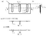
図2(a)から図2(c)は扁平管50が挿入される前の板状フィン1の構造を示す図である。図2(a)は板状フィン1に平行な平面で見た図、図2(b)は板状フィン1を側面から見た図、図2(c)は板状フィン1を図2(a)に示す線A―A’及びB―B’で切断したときの断面図である。
板状フィン1は、平板状であって複数の切り欠き部10が設けられている。各切り欠き部10は同一形状であって、長手方向に等間隔で設けられている。図2(a)に示す例では、切り欠き部10は概U字状に形成されている。以下では、U字のうち開口側から延びる延伸部分を延伸部11とし、切り欠き部10の先端側の先端部分を先端部12と記述する。なお、先端部12は必ずしも曲線状である必要はなく、直線状であってもよい。その場合、先端部12は二本の直線から構成された先細り状の形状となる。また、後述するように延伸部11の一部には保持部14が設けられている。
切り欠き部10の周縁部、すなわち延伸部11と先端部12とからは、フィンカラー13が板状フィン1の厚み方向に概垂直に立設される。すなわち、図2(a)のように板状フィン1に平行な平面で見た場合、フィンカラー13は切り欠き部10と同様に概U字状になっている。図2(b)のように板状フィン1を側面から見ると、1[mm]から数mm程度の高さのフィンカラー13が、切り欠き部10の奥行き方向に一様な高さで伸びている。なお図2(b)ではフィンカラー13は一部欠落しているが、これは後述する保持部14が設けられるためである。
ここで図2(a)及び図2(b)に示すように、延伸部11の一部には保持部14が設けられている。保持部14は、切り欠き部10の内側に向かって突出するドーム状の凸部である。図2(c)に示される線A―A’と、線B-B’とでの板状フィン1の断面を比較すると、断面A―A’では切り欠き部10の左右にフィンカラー13が設けられているが、断面B-B’では切り欠き部10の左右に保持部14が設けられている。なお、断面B-B’では保持部14を太線で示しているが、これは図の表現のためであり実際に保持部14が太く成形されているわけではない。
また、ここで断面A―A’と断面B―B’とでの対向する延伸部11の間の距離、すなわち切り欠き部10の幅を比較すると、保持部14が設けられているために、断面B―B’の方が断面A―A’よりも狭くなっている。また後述するように、断面A―A’での切り欠き部10の幅は、後述する扁平管50の幅よりわずかに大きく、保持部14が設けられている断面B―B’での切り欠き部10の幅は、扁平管50の幅より小さい。
図3は、扁平管50の断面形状を示す図である。扁平管50は例えば、アルミニウム、アルミニウム合金、銅などの熱伝導率の高い金属で成形される。扁平管50の外形は扁平部51と曲面部52とから構成され、断面形状は両端部が半円形の概長円形である。また、扁平管50の内部には熱媒体(冷媒など)が流れる流路53が成形されている。なお流路53の形状は特に限定されず、例えば円形であってもよい。
なお、扁平管50の一端(紙面手前側もしくは奥側)には、複数の扁平管50の流路53を接続する図示しないヘアピン管が取り付けられている。この場合、ある扁平管50の流路53を紙面手前側から奥側に流れた冷媒は、上記ヘアピン管で折り返して別の扁平管50の流路53を紙面奥側から手前側に流れてくる。なお、同様の機能を発揮できるのであれば、扁平管50の一端に取り付けるのはヘアピン管でなく円管でもよい。
また扁平管50の他端には、図示しないヘッダーパイプが接続されている。上記ヘッダーパイプは熱交換器100に流入する熱媒体を、複数の扁平管50に均等に分配する機能を発揮する。なお、必要であれば熱交換器100には上記ヘアピン管を取り付けず、両端にヘッダーパイプを取り付けた構造としてもよい。
図4(a)から図4(d)は扁平管50を切り欠き部10に挿入する過程の図である。図4(a)、図4(b)及び図4(c)は板状フィン1に平行な平面から見た図であって、図4(a)及び図4(b)は扁平管50を切り欠き部10に挿入する途中の図、図4(c)は扁平管50を切り欠き部10に挿入した状態の図である。なお、図4(a)から図4(c)の線A-A’及び線B-B’は、図2(a)に示す線A-A’及び線B-B’と同一の位置の線である。また、図4(d)は図4(c)における線A-A’及び線B-B’での断面図である。
図4(a)に示す状態において、扁平管50は切り欠き部10の開口側から破線矢印の方向に移動する。板状フィン1の切り欠き部10の形状と、扁平管50の断面形状とは概同一であり、かつ切り欠き部10の大きさは扁平管50の断面より僅かに大きい。より詳細には、対向する延伸部11同士の間の距離は、扁平管50の幅(断面形状における扁平部51同士の距離)より大きい。したがって、図4(a)のように板状フィン1に扁平管50が挿入される途中では、扁平管50と切り欠き部10との間に僅かな隙間が生じる。よって、図4(a)に示す状態に置いては、小さな力で扁平管50を挿入することができる。
続いて、図4(b)に示す状態では扁平管50の扁平部51が保持部14に到達している。このとき、対向する保持部14同士の距離は、扁平管50の幅より短い。したがって、断面B-B’においては、図4(d)に示すように保持部14と扁平管50の扁平部51とが接触する。なお、このときの保持部14と扁平部51とは、保持部14が小さい凸部状であるために線接触となる。したがって、図4(b)に示す状態においても、最小限の力で扁平管50を挿入することができる。
図4(b)に示す状態からさらに扁平管50を挿入していくと、図4(c)のように扁平管50が切り欠き部10に完全に挿入された状態となる。なお、図4(c)に示す状態に置いては、延伸部11及び先端部12から立設されるフィンカラー13が扁平管50を支える状態となる。図4(d)は断面A-A’の状態を示しているが、フィンカラー13が扁平管50を左右から挟んで支えている。これにより、扁平管50は板状フィン1に対して概垂直な状態を保つことができる。
なお以上説明した構成は、本開示における熱交換器100の機能を発揮させる最低限の構成であり、熱交換器100は本開示の趣旨を逸脱しない範囲で種々変形することが可能である。
例えば、保持部14の位置は図2及び図4に示される位置に限らず任意の位置とすることができる。しかしながら、保持部14は延伸部11の半分より先端部12よりに配置されることが望ましい。これは保持部14を延伸部11の奥側に設けると、扁平管50を切り欠き部10に挿入する際に保持部14と扁平管50とが接触するタイミングを遅くでき、扁平管50を小さな力で挿入できる範囲が増加するからである。
しかしながら、保持部14が先端部12側に寄りすぎている場合、扁平管50を切り欠き部10に挿入した後に、扁平管50が切り欠き部10から脱落する可能性が発生する。例えば、保持部14が先端部12のすぐそばにある場合、扁平管50が切り欠き部10に挿入された状態において、扁平管50が切り欠き部10の開口側にわずかにずれただけでも、保持部14と扁平管50の接触が弱くなり扁平管50が切り欠き部10から脱落する可能性がある。
したがって、保持部14の位置は切り欠き部10の半分より奥側で、かつ、先端部12からは離れていることが望ましい。このように保持部14の位置を決めることで、扁平管50を小さな力で切り欠き部10に挿入できるとともに、扁平管50が切り欠き部10から脱落する可能性が低くなる。
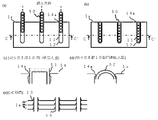
例えば、板状フィン1には複数のスペーシングタブを設けてもよい。スペーシングタブは、板状フィン1に扁平管50が挿入されたときに、複数の板状フィン1同士の間隔を保つ機能を発揮する。図5(a)及び図5(b)はスペーシングタブ16が設けられた場合の板状フィン1の構造を示す図である。図5(a)に示すように、同一の形状のスペーシングタブ16が板状フィン1に所定の間隔で設けられている。
図5(b)は扁平管50に板状フィン1が組み合わされた状態での、線A-A’での板状フィン1の断面図である。図5(b)に示すように、各スペーシングタブ16は板状フィン1に対して垂直に立設され、先端が直角に折り曲げられた鉤状の形状となっている。扁平管50に板状フィン1が組み合わされた状態では、ある板状フィン1に設けられたスペーシングタブ16が、隣接する板状フィン1と接触している。より具体的には、スペーシングタブ16の折り曲げられた先端部分が、隣接する板状フィン1と面接触し、二つの板状フィン1同士の間隔を保持する。これにより、複数の板状フィン1同士の間隔が一定に保たれ、熱交換器100の性能が向上する。
また他の変形例として、板状フィン1に切り起こしなどの乱流促進部を設けてもよい。上記乱流促進部は熱交換器100に供給される気流に乱流を発生させ、空気と板状フィン1との間の熱交換を促進する。乱流は基本的に板状フィン1に凹凸を設けることで促進され、乱流促進部の具体的形状としては、矩形状の凹凸、板状フィン1と垂直な三角形のフィン、板状フィン1を貫通する孔などがあげられる。なお、乱流促進部は板状フィン1に任意の数、適当な間隔で成形してよい。
また更なる変形例として、板状フィン1は、その表面にロウ材が塗布されたいわゆるクラッドフィンであってもよい。この場合、板状フィン1に扁平管50が挿入された後の工程で、熱交換器100は電気炉などの加熱装置に投入される。熱交換器100が加熱されると、塗布されたロウ材は熱によって溶け、板状フィン1の表面を流れる。このとき、ロウ材は扁平管50と板状フィン1との間の隙間や、扁平管50と板状フィン1との接触部分付近に流れ込む。
この後、熱交換器100が冷却されるとロウ材が固化し、ロウ材は板状フィン1と扁平管50とを接着させる接着剤として機能する。これにより板状フィン1と扁平管50とを強固に接着させることができる。また、板状フィン1と扁平管50との間の隙間がロウ材で埋められるため、熱交換器100の性能も向上する。
なお板状フィン1がクラッドフィンである場合、ロウ材は切り欠き部10の先端部12側を中心に、板状フィン1の裏表両面、もしくは、どちらか片面に塗布するようにしてよい。あるいは、ロウ材は板状フィン1の切り欠き部10、及びフィンカラー13に沿って塗布するようにしてもよい。ロウ材の塗布の量や範囲は、板状フィン1及び扁平管50のサイズや形状に応じて適宜設定してよい。
さらに板状フィン1がクラッドフィンである場合、先端部12の先端に切り込み状の誘導部15を設けてもよい。図6は誘導部15を設けた場合の板状フィン1の構造を示す図である。誘導部15は上記ロウ付けの工程において、ロウ材が適切な位置に流入するように誘導する機能を持つ。具体的には、ロウ材が溶け始めるとロウ材は誘導部15に流れ込み、そのまま切り欠き部10及びフィンカラー13と、扁平管50との間に充填されていく。これにより、より強固に板状フィン1と扁平管50とがロウ付けされる。
熱交換器の製造方法
続いて、本実施の形態における熱交換器100の製造方法について説明する。ここでは板状フィン1はクラッドフィンとして説明を行う。板状フィン1の素材であるロウ材が塗布された金属板材に、切り欠き加工あるいはプレス加工などを施し、切り欠きを成形する(工程1)。なおこの時の切り欠きは切り欠き部10と形状は類似しているが、その大きさは切り欠き部10より小さい。以下では上記小さい切り欠き部を”仮切り欠き部”と表記する。
続いて、本実施の形態における熱交換器100の製造方法について説明する。ここでは板状フィン1はクラッドフィンとして説明を行う。板状フィン1の素材であるロウ材が塗布された金属板材に、切り欠き加工あるいはプレス加工などを施し、切り欠きを成形する(工程1)。なおこの時の切り欠きは切り欠き部10と形状は類似しているが、その大きさは切り欠き部10より小さい。以下では上記小さい切り欠き部を”仮切り欠き部”と表記する。
なお工程1で仮切り欠き部を成形する際、保持部14を同時に成形することができる。図7(a)及び図7(b)は工程1での金属板材の加工方法の一例を示す図である。図7(a)は仮切り欠き部全体を含む加工の様子、図7(b)は図7(a)に示す円内の拡大図である。なお、図7(a)及び図7(b)には後の工程で用いるロウ材も示されている。
図7(a)では仮切り欠き部を網掛けで、後の工程で成形する切り欠き部10を鎖線で表している。図7(a)に示されるように、仮切り欠き部は切り欠き部10より小さい。仮切り欠き部と切り欠き部10の延伸部11、及び仮切り欠き部と切り欠き部10の先端部12との間の部分は、後の工程で立設されフィンカラー13となる。そのため、仮切り欠き部と切り欠き部10との間隔は数ミリメートル程度にしておくことが望ましい。
さらに図7(b)に示すように、保持部14は工程1で完成形に成形しておいてもよい。これは後の工程で保持部14にあたる部分にはフィンカラー13を設けないためである。
続いて、仮切り欠き部と切り欠き部10との間の部分に曲げ加工などを施し、当該部分を板状フィン1に垂直に立設してフィンカラー13を成形する(工程2)。このとき仮切り欠き部の周縁部が立設されることによって切り欠きが拡大し、切り欠き部10が成形される。これにより板状フィン1が完成する。
さらに、板状フィン1にスペーシングタブ16、乱流促進部、及び誘導部15を設ける場合は、目的に沿った加工方法により必要な加工を施して成形する。
以上のように成形された複数の板状フィン1を、切り欠き部10の開口側が鉛直上方にくるように装置に固定し、扁平管50を挿入する(工程3)。板状フィン1に扁平管50が完全に挿入された状態では、保持部14は扁平管50の扁平部51を両側から挟んでおり、扁平管50と板状フィン1との位置関係を保持する機能を発揮する。なお、工程3では扁平管50を固定し板状フィン1を動かして組み付ける方式にしてもよい。このように扁平管50が挿入された板状フィン1を、以下では”仮組みされた熱交換器”と表記する。
続いて仮組みされた熱交換器は、切り欠き部10の開口側が鉛直下方にくるよう姿勢変更される(工程4)。このとき、仮組みされた熱交換器の姿勢変更は、手動で行ってもよいし装置で行ってもよい。いずれの方法をとるにしても、扁平管50と板状フィン1と位置関係は、保持部14により保持されているため、扁平管50が板状フィン1から脱落したり位置ずれをおこしたりする虞は少ない。
続いて仮組された熱交換器は、上記姿勢のまま電気炉などの加熱装置に投入される。加熱装置により加熱が行われると、板状フィン1に塗布されたロウ材が溶ける(工程5)。図8(a)及び図8(b)は加熱が行われる前後でのロウ材の状態を示す図である。図8(a)で、板状フィン1の先端部12側に塗布されたロウ材は加熱により溶けだし、板状フィン1に沿って鉛直下方、すなわち切り欠き部10の開口側に流れ出す。
流れ出したロウ材は、図8(b)に示すように切り欠き部10及びフィンカラー13と、扁平管50との隙間に充填される。このようにして板状フィン1と扁平管50とがロウ付けされる。なお上記のようなロウを介した扁平部50とフィンカラー13との接着において、フィンカラー13の高さが一様に形成されていると、扁平管50とフィンカラー13との接着面が延伸部11方向に偏りなく広く生成されるので、扁平管50に力が加わったときにロウ材が破壊され接着が弱くなる可能性が低くなる。
続いて、仮組された熱交換器を加熱装置から取り出し、冷却を行う(工程6)。このとき冷却方法は限定しないが、切り欠き部10の開口側から冷却していくことが望ましい。このように冷却を行うことで、溶けだしたロウ材のうち切り欠き部10の開口側のロウ材が先に固化し、その後開口側から上方に向かってロウ材が固化していく。これにより、ロウ材が板状フィン1から落下する可能性が低くなるため、板状フィン1と扁平管50とが強固に接着されるとともに、完成した熱交換器100の性能が向上する。以上の工程を経ることによって、熱交換器100が製造される。
以上説明した熱交換器100は以下のような効果を奏する。扁平管50を板状フィン1の切り欠き部10に挿入する際、扁平管50と接触するのは保持部14のみのため、少ない力で扁平管50を挿入することができる。
また扁平管50を板状フィン1に挿入した後、保持部14が扁平管50の扁平部51と接触し、板状フィン1と扁平管50との位置関係を保持する。これによりロウ付け前に熱交換器100の姿勢を変更したとしても、扁平管50が板状フィン1から脱落したり位置ずれを起こしたりする可能性が低い。
また保持部14は、切り欠き部10に挿入された扁平管50の扁平部51を左右から挟みこむように保持する。したがって、扁平管50の切り欠き部10への挿入方向において、保持部14が扁平管50の寸法を制限することがない。よって、長さが異なる複数の種類の扁平管50に対して同じ形状の板状フィン1を適用することができ、低コストで設計の自由度を確保することができる。
また対向する保持部14同士の距離は、扁平管50の幅よりも短い。これにより、切り欠き部10に挿入された扁平管50に対し、金属材料がもつばね性が作用する。これにより、扁平管50を設計した位置に正確に配置できる可能性が高まる。
なお板状フィン1はアルミニウム、アルミニウム合金、銅などの金属材料で作成されるが、材料としてJIS(Japanese In dustrial Standards)などで規格されるばね材料を用いてもよい。板状フィン1にばね材料を用いることで、保持部14が発揮する力が大きくなり、扁平管50が板状フィン1から脱落したり位置ずれを起こしたりする可能性をより低くできる。
なお本実施の形態における熱交換器100を作成した場合、その技術的な特徴部分である板状フィン1の保持部14は、ロウ付け後にはロウ材に覆われて外から確認できない場合がある。したがって、保持部14が設けられていることを確認するには、ロウを加熱して溶かす必要がある。ロウ材を溶かすことで、保持部14の存在を確認することができる。
また、保持部14は扁平管50の挿入によって変形し確認が難しくなる場合がある。その場合、保持部14を設けない従来の扁平管熱交換器では、板状フィン1に垂直な方向に一様の高さを持つ場合が多いフィンカラー13において、あえてフィンカラー13の一部を欠落させていることで、本実施の形態の技術的特徴を有する熱交換器100である可能性が含まれる。あるいは、扁平管50の扁平部51のうち、扁平管50が切り欠き部10に挿入された状態で、保持部14より奥に位置する部分に擦過の形跡があることを確認することで、本実施の形態の技術的特徴を有する熱交換器100であるか否かを判断することができる。
実施の形態2.
図9及び図10を参照しながら、本開示の実施の形態2について説明する。本実施の形態の熱交換器100aの構成は、実施の形態1の熱交換器100と概ね同一であるが、板状フィンの形状や発揮される機能が異なる。以下、本実施の形態に係る熱交換器100aについて、実施の形態1との相違点を中心に説明する。説明を省略した部分については実施の形態1と同一である。
図9及び図10を参照しながら、本開示の実施の形態2について説明する。本実施の形態の熱交換器100aの構成は、実施の形態1の熱交換器100と概ね同一であるが、板状フィンの形状や発揮される機能が異なる。以下、本実施の形態に係る熱交換器100aについて、実施の形態1との相違点を中心に説明する。説明を省略した部分については実施の形態1と同一である。
熱交換器の構成
図9(a)から図9(c)は本実施の形態における板状フィン1aの形状を示す図である。図9(a)は板状フィン1aに平行な平面で見た図、図9(b)は板状フィン1aを側面から見たときの図、図9(c)は板状フィン1aを切り欠き部10aの開口部及び線C―C’で切断したときの断面図である。
図9(a)から図9(c)は本実施の形態における板状フィン1aの形状を示す図である。図9(a)は板状フィン1aに平行な平面で見た図、図9(b)は板状フィン1aを側面から見たときの図、図9(c)は板状フィン1aを切り欠き部10aの開口部及び線C―C’で切断したときの断面図である。
図9(a)に示すように、本実施の形態における板状フィン1aの切り欠き部10aは、延伸部11及び先端部12を有する点で実施の形態1の板状フィン1と共通する。一方、板状フィン1aの保持部14aは切り欠き部10aの開口部に設けられており、板状フィン1の保持部14と比較して位置が異なる。また保持部14aの大きさは任意に決定することができる。
なお保持部14aの形状は、曲線部分を有する形状であることが望ましい。例えば、保持部14aの形状は図9あるいは後述する図10に示す半円形状などであることが望ましい。上記保持部14aの曲線部分は、後述するように切り欠き部10aに挿入された扁平管50の曲面部52と接触する。
図9(b)は板状フィン1aを側面から見たときの図である。実施の形態1と同様に、延伸部11と先端部12の周縁部からは、フィンカラー13が概垂直に立設されている。ここで、図9(a)に示す切り欠き部10aの開口部の位置と、図9(b)に示すフィンカラー13の位置とを比較すると、フィンカラー13は切り欠き部10aの開口部において欠落している。これは本実施の形態において保持部14aが切り欠き部10aの開口部に設けられており、当該部分にはフィンカラー13が立設されないからである。なお実施の形態1と同様に、本実施の形態においてもフィンカラー13の高さは特に限定されず、1[mm]から数mm程度である。
図9(c)は切り欠き部10aの開口部及び線C-C’で板状フィン1aを切断したときの、板状フィン1aの断面図である。板状フィン1aでは、保持部14aは切り欠き部10aの開口部に設けられており、切り欠き部10aの開口部の幅は小さくなっている。一方、本実施の形態においては延伸部11に保持部14aは設けられていないため、対向する延伸部11同士の距離は大きい。
図10(a)から図10(e)は扁平管50を切り欠き部10aに挿入する時の図である。図10(a)及び図10(b)は板状フィン1aに平行な平面から見た図であって、図10(a)は扁平管50を切り欠き部10aに挿入する途中の図、図10(b)は扁平管50を切り欠き部10aに挿入した状態の図である。なお、図10(a)及び図10(b)の線C-C’は、図9(a)に示す線C-C’と同一の位置の線である。また、図10(c)及び図10(d)は扁平管50を切り欠き部10aに挿入する途中、及び挿入した状態における、切り欠き部10aの開口部の拡大図である。また図10(e)は扁平管50を切り欠き部10aに挿入した状態における、線C-C’での板状フィン1aの断面図である。
図10(a)に示す状態において、扁平管50は切り欠き部10aの開口側から破線矢印の方向に移動する。板状フィン1aでは保持部14aが切り欠き部10aの開口部に設けられており、対向する保持部14a同士の距離は、扁平管50の幅より小さい。したがって、扁平管50を切り欠き部10aに挿入する際には、図10(c)に示すように扁平管50が保持部14aと接触して切り欠き部10aを外に押し広げる。なお、ここで保持部14aは板状フィン1aの厚み方向に一様の形状であるため、保持部14aと扁平管50とは線接触となる。
図10(b)は扁平管50を切り欠き部10aに挿入した状態の図である。このとき切り欠き部10aの開口部では、図10(d)に示すように保持部14aの曲線部分と曲面部52とが接触しており、保持部14aが扁平管50を固定している。この状態においては、例えば切り欠き部10aの開口部を鉛直下方に向けたとしても、保持部14aに扁平管50が引っかかる。したがって、扁平管50の位置がずれる、あるいは扁平管50が切り欠き部10aから脱落するといった虞が少ない。
ここで扁平管50の断面形状と、切り欠き部10aの形状と、は概同一である。また板状フィン1aでは、図10(b)に示す状態において扁平管50の扁平部51と、保持部14aとが接触することがない。したがって本実施の形態においては、対向する延伸部11同士の距離と、扁平管50の幅とをほぼ一致させることができ、図10(e)に示すように延伸部11と扁平部51との間に生じる隙間が小さくなる。同時に、扁平管50に対するフィンカラー13の接触面積が大きくなため、扁平管50の位置を規定するフィンカラー13の役割がより強く発揮される。
なお、本実施の形態において保持部14aの位置は図9及び図10に示す位置に限定されない。具体的には、保持部14aは扁平管50を切り欠き部10aに挿入した時に、その曲線部分が扁平管50の曲面部52と接触する位置に配置されていればよい。よって、保持部14aは切り欠き部10aの端部以外にも、切り欠き部10aの端部からわずかに切り欠き部10aの奥側に入った位置に配置されていてもよい。
保持部14aが切り欠き部10aの端部に配置されている場合と、保持部14aが切り欠き部10の端部からわずかに切り欠き部10aの奥側に入った位置に配置されている場合とでは、それぞれに利点がある。まず、保持部14aが切り欠き部10aの端部に配置されている場合は、扁平管50を切り欠き部10aに挿入した時に、保持部14aが扁平管50の曲面部52を包み込むように保持するため、扁平管50が切り欠き部10aから脱落する可能性が低くなる。
一方、保持部14aが切り欠き部10の端部からわずかに切り欠き部10aの奥側に入った位置に配置されている場合、切り欠き部10aの開口部の幅が大きくなるため、扁平管50を切り欠き部10aに挿入する際の位置合わせがしやすくなり、扁平管50が切り欠き部10aに挿入しやすくなる。
以上のように、保持部14aの位置は、扁平管50が切り欠き部10aに挿入された際に、保持部14aの曲線部分と扁平管50の曲面部52とが接触する位置であればよい。より詳細な保持部14aの位置は、それぞれの利点に応じて設計者が決めることができる。
熱交換器の製造方法
続いて、本実施の形態における熱交換器100aの製造方法について説明する。以下では、実施の形態1の熱交換器100の製造方法と比較して、異なる部分を中心に説明する。説明を省略した部分については、実施の形態1と同様である。
続いて、本実施の形態における熱交換器100aの製造方法について説明する。以下では、実施の形態1の熱交換器100の製造方法と比較して、異なる部分を中心に説明する。説明を省略した部分については、実施の形態1と同様である。
まず板状フィン1aの素材であるロウ材が塗布された金属板材に、切り欠き加工あるいはプレス加工などにより仮切り欠き部を成形する(工程1)。仮切り欠き部は切り欠き部10aと形状は類似しているが、その大きさは切り欠き部10aより小さい。また工程1で仮切り欠き部を成形する際、保持部14aを同時に成形することができる。具体的には、実施の形態1と同様に、後工程でフィンカラー13を設けない部分について、工程1で最終的な形状に成形する。
続いて、仮切り欠き部の周縁部に沿って曲げ加工などを施し、フィンカラー13を成形する(工程2)。このとき仮切り欠き部が拡大し、切り欠き部10aが成形される。これにより板状フィン1が完成する。
以上のように成形された複数の板状フィン1aを、切り欠き部10aの開口側が鉛直上方にくるように装置に固定し、扁平管50を挿入する(工程3)。板状フィン1aの開口部に設けられた保持部14aに扁平部51の先端が到達すると、扁平管50は保持部14aと接触して切り欠き部10aを外側に押し広げつつ、切り欠き部10aの奥に挿入されていく。
扁平管50が切り欠き部10aに完全に挿入された状態では、保持部14aは扁平管50の曲面部52と接触して扁平管50を抑えており、扁平管50の位置を保持する機能を発揮する。このようにして熱交換器100aは仮組みされる。
続いて仮組みされた熱交換器は、切り欠き部10aの開口側が鉛直下方にくる姿勢となるように配置される(工程4)。このとき、保持部14aは扁平管50の曲面部52を抑えているため、扁平管50が板状フィン1aから脱落したり位置がずれたりする虞は少ない。
続いて仮組された熱交換器は、上記姿勢のまま電気炉などの加熱装置に投入されロウ付けされる(工程5)。切り欠き部10aの先端部12側に塗布されたロウ材は加熱により溶けだし、切り欠き部10aの開口側に流れ出す。
続いて、ロウ付け済みの仮組された熱交換器を加熱装置から取り出し、冷却を行う(工程6)。以上の工程を経ることによって、熱交換器100aが製造される。
以上説明した熱交換器100aは、実施の形態1における熱交換器100の効果に加え、以下のような効果を奏する。扁平管50を板状フィン1aに挿入した後は、保持部14aは扁平管50の曲面部52とのみ接触する。そのため、切り欠き部10aと扁平管50との間に生じる隙間が小さくなり、熱交換器100aの伝熱性を高めることができる。
また、切り欠き部10aに扁平管50が挿入された後、保持部14aの曲線部分と扁平管50の曲面部52とのみが接触するため、扁平管50と保持部14aとが接触する部分が小さい。したがって、切り欠き部10への扁平管50の挿入に伴って生じる板状フィン1aの歪みが小さくなり、あらかじめ設計した寸法道理の扁平管熱交換器が形成される可能性が高くなる。
なお本実施の形態における、熱交換器100aの技術的な特徴である保持部14aの存在は、実施の形態1と同様の方法により確認される。すなわち、ロウを溶かした後の目視、フィンカラー13の一部欠落、扁平部51の擦過の形跡などにより、熱交換器100aであるか否かを判断することができる。
実施の形態3.
図11から図13を参照しながら、本開示の実施の形態3について説明する。本実施の形態の熱交換器100bの構成は、実施の形態1の熱交換器100及び実施の形態2の熱交換器100aと概ね同一であるが、板状フィンの形状や発揮される機能が異なる。以下、この本実施の形態に係る熱交換器100bについて、実施の形態1及び実施の形態2との相違点を中心に説明する。説明を省略した構成については実施の形態1及び実施の形態2と同一である。
図11から図13を参照しながら、本開示の実施の形態3について説明する。本実施の形態の熱交換器100bの構成は、実施の形態1の熱交換器100及び実施の形態2の熱交換器100aと概ね同一であるが、板状フィンの形状や発揮される機能が異なる。以下、この本実施の形態に係る熱交換器100bについて、実施の形態1及び実施の形態2との相違点を中心に説明する。説明を省略した構成については実施の形態1及び実施の形態2と同一である。
熱交換器の構成
図11(a)から図11(c)は本実施の形態における板状フィン1bの形状を示す図である。図11(a)は板状フィン1bに平行な平面で見た図、図11(b)は板状フィン1bを側面から見た図、図11(c)は板状フィン1bを図11(a)に示す線D―D’及び線E―E’で切断したときの断面図である。
図11(a)から図11(c)は本実施の形態における板状フィン1bの形状を示す図である。図11(a)は板状フィン1bに平行な平面で見た図、図11(b)は板状フィン1bを側面から見た図、図11(c)は板状フィン1bを図11(a)に示す線D―D’及び線E―E’で切断したときの断面図である。
図11(a)に示すように、本実施の形態における板状フィン1bの切り欠き部10bは、延伸部11及び先端部12を有する点で、実施の形態1、2の板状フィン1、1aと共通する。一方、延伸部11全体より立設されるフィンカラーが、延伸部11に対し概垂直ではなく、その先端が切り欠き部10bの内側方向に傾くように設けられている点が、実施の形態1、2と異なる。なおここで、フィンカラーの先端とは延伸部11と逆側の部分を意味する。
これにより、本実施の形態におけるフィンカラーは切り欠き部10bに挿入される扁平管50を保持する機能を発揮する。よって、以下では延伸部11から立設するフィンカラーは、保持部と一体化したものとして、保持部14bと表記して説明を行う。なお、先端部12から立設するフィンカラー13は、実施の形態1、2と同様に先端部12に対し概垂直に立設される。
図11(b)は板状フィン1bを側面から見たときの図である。板状フィン1bでは、延伸部11から立設する保持部14bは、その先端が切り欠き部10bの内側に向くよう傾斜している。一方、先端部12から立設するフィンカラー13は、先端部12に対し概垂直である。そのため、切り欠き部10bに扁平管50が挿入されていない状態においては、保持部14bとフィンカラー13との見かけ上の高さが異なる場合がある。なお、このことは保持部14bとフィンカラー13との関係を限定するものではなく、それぞれの高さは独立して任意に決定することができる。
図11(c)は板状フィン1bを線D-D’及び線E-E’で切断したときの断面図である。板状フィン1bにおいては、保持部14bはその先端部が切り欠き部10bの内側に向いている。したがって、図11(c)に示すように保持部14bの先端間の幅は、保持部14bの根元間の幅と比較して狭くなっている。また後述するように、保持部14bの先端間の幅は扁平管50の幅より狭く、保持部14bの根元間の幅は扁平管50の幅より大きい。
図12(a)から図12(c)は扁平管50を切り欠き部10bに挿入する時の図である。図12(a)及び図12(b)は板状フィン1bに平行な平面から見た図であって、図12(a)は扁平管50を切り欠き部10bに挿入する途中の図、図12(b)は扁平管50を切り欠き部10bに挿入した状態の図である。なお、線D-D’及び線E-E’は、図11(a)に示す線D-D’及び線E-E’と同一の位置の線である。また、図12(c)は扁平管50を切り欠き部10bに挿入する前及び挿入した状態における、線D-D’での板状フィン1bの断面図である。
図12(a)に示す状態において、扁平管50は切り欠き部10bの開口側から破線矢印の方向に移動する。板状フィン1bでは保持部14bが延伸部11から立設されており、保持部14bの先端間の幅は扁平管50の幅よりも狭い。したがって、扁平管50が切り欠き部10bに挿入されると、扁平部51は保持部14bと接触し、保持部14bを押し広げつつ挿入される。扁平管50が切り欠き部10bに完全に挿入されると、図12(b)に示す状態となる。
図12(c)は扁平管50が切り欠き部10bに挿入される前後での、保持部14bの変化を示している。扁平管50が挿入される前は、保持部14bは傾斜しておりその先端間の幅は扁平管50の幅よりも小さい。一方、切り欠き部10bに扁平管50が挿入されると、保持部14bは扁平管50により押し広げられ、延伸部11に対して概垂直となる。
上記状態では保持部14bは扁平部51と接触し、扁平管50を左右から挟んで保持する。よってこのとき、切り欠き部10bの開口部を鉛直下方に向けたとしても、扁平管50の位置がずれる、あるいは扁平管50が切り欠き部10bから脱落するといった虞が少なくなる。
熱交換器の製造方法
続いて、本実施の形態における熱交換器100bの製造方法について説明する。以下では、実施の形態1、2の熱交換器100、100aの製造方法と比較して異なる部分を中心に説明する。説明を省略した部分については、実施の形態1、2と同様である。
続いて、本実施の形態における熱交換器100bの製造方法について説明する。以下では、実施の形態1、2の熱交換器100、100aの製造方法と比較して異なる部分を中心に説明する。説明を省略した部分については、実施の形態1、2と同様である。
まず板状フィン1bの素材であるロウ材が塗布された金属板材に、切り欠き加工あるいはプレス加工などにより仮切り欠き部を成形する(工程1)。図13(a)、(b)は工程1での金属板材の加工方法の一例を示す図である。仮切り欠き部は切り欠き部10bと形状は類似しているが、その大きさは切り欠き部10bより小さい。
また工程1では、次工程で成形される切り欠き部10bの延伸部11と先端部12との境目に、切り込みを入れる。これは次工程で保持部14bと、先端部12から立設するフィンカラー13と、を分離して成形するためである。図13(b)は工程1に示す円内の拡大図である。図13(b)に示すように、仮切り欠き部から、次工程で成形される延伸部11と先端部12との境目に切り込みを入れる。このように切り込みを入れることで、次工程で保持部14bとフィンカラー13とを分離して成形することができる。
続いて、仮切り欠き部の周縁部に沿って曲げ加工などを施し、保持部14b及びフィンカラー13を成形する(工程2)。このとき仮切り欠き部が拡大し、切り欠き部10bが成形される。
工程2では、フィンカラー13は先端部12の周縁部から垂直に立設される。一方、保持部14bは延伸部12に対し、垂直未満の角度で、その先端部分が切り欠き部10bの内側に向くように成形される。このように成形することで、保持部14bの先端間の幅を狭くすることができる。
以上のように成形された複数の板状フィン1bを、切り欠き部10bの開口側が鉛直上方にくるように装置に固定し、扁平管50を挿入する(工程3)。扁平管50は保持部14bの先端部分と接触し、保持部14bを外側に押し広げながら切り欠き部10bに挿入される。扁平管50が切り欠き部10bに挿入された状態では、保持部14bは扁平管50を左右から挟んで扁平管50を保持する機能を発揮する。このようにして熱交換器100bは仮組みされる。
続いて仮組みされた熱交換器は、切り欠き部10bの開口側が鉛直下方にくるよう配置される(工程4)。このとき、保持部14bは扁平管50を左右から挟んで保持しているため、扁平管50が板状フィン1bから脱落したり位置がずれたりする虞は少ない。
続いて仮組された熱交換器は、上記姿勢のまま電気炉などの加熱装置に投入されロウ付けされる(工程5)。続いて、ロウ付け済みの仮組された熱交換器を加熱装置から取り出し冷却を行う(工程6)。以上の工程を経ることによって、熱交換器100bが製造される。
以上説明した熱交換器100bは、以下のような効果を奏する。扁平管50を板状フィン1bに挿入した後は、保持部14bが左右から広範囲に扁平管50を挟んで保持するため、板状フィン1bから扁平管50が脱落する、あるいは扁平管50の位置がずれるといった虞が少ない。
また扁平管50を板状フィン1bに挿入する際、保持部14bと扁平管50とは線接触となるため、扁平管50を板状フィン1bに少ない力で挿入することができる。
また扁平管50を板状フィン1bに挿入する際、保持部14bは左右に押し広げられるように変形するが、板状フィン1bの保持部14以外の部分、例えば板状フィン1bの平板部分は変形する可能性が低い。したがって、扁平管50を板状フィン1bに挿入する場合、板状フィン1bに余計な変形が発生する虞が少ない。
また扁平管50が切り欠き部10bに挿入された状態では、扁平管50が保持部14bを左右に押し広げる。このとき、保持部14bから扁平管50に金属材料がもつばね性が作用し、扁平管50を左右から挟む力が強くなる。これにより、扁平管50を設計した位置に正確に配置できる可能性が高まる。
なお本実施の形態における、熱交換器100bの技術的な特徴である保持部14bの存在は、扁平管50が板状フィン1bに挿入された後では、保持部14bの角度が変化するために目視での確認が難しくなる。この場合、保持部14bの存在は以下のようにして確認される。まず、扁平管50を板状フィン1bに挿入する際、保持部14bと扁平管50とが線接触するので、扁平管50の扁平部51に線状の擦過の形跡があることで保持部14bの存在を確認できる。
あるいは、切り欠き部10bの延伸部11から立設される保持部14bと、先端部12から立設されるフィンカラー13との間には切り込みがある。したがって、延伸部11から立設している部分と、先端部12から立設している部分との間に切り込みが入っていることでも保持部14bの存在を確認することができる。
実施の形態4.
図14から図16を参照しながら、本開示の実施の形態4について説明する。本実施の形態の熱交換器100cの構成及び動作は、実施の形態3の熱交換器100bと概ね同一であるが、板状フィンの形状や発揮される機能が異なる。以下、本実施の形態に係る熱交換器100cについて、実施の形態3との相違点を中心に説明する。説明を省略した構成については実施の形態3と同一である。
図14から図16を参照しながら、本開示の実施の形態4について説明する。本実施の形態の熱交換器100cの構成及び動作は、実施の形態3の熱交換器100bと概ね同一であるが、板状フィンの形状や発揮される機能が異なる。以下、本実施の形態に係る熱交換器100cについて、実施の形態3との相違点を中心に説明する。説明を省略した構成については実施の形態3と同一である。
熱交換器の構成
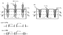
図14(a)から図14(c)は本実施の形態における板状フィン1cの形状を示す図である。図14(a)は板状フィン1cに平行な平面で見た図、図14(b)は板状フィン1cを側面から見たときの図、図14(c)は板状フィン1cを図14(a)に示す線F―F’及び線G―G’で切断したときの断面図である。
図14(a)から図14(c)は本実施の形態における板状フィン1cの形状を示す図である。図14(a)は板状フィン1cに平行な平面で見た図、図14(b)は板状フィン1cを側面から見たときの図、図14(c)は板状フィン1cを図14(a)に示す線F―F’及び線G―G’で切断したときの断面図である。
図14(a)に示すように、本実施の形態における板状フィン1cの切り欠き部10cは、開口部が広く先端部が狭い、所謂テーパ状になっている点が実施の形態3と異なる。なお、切り欠き部10cが開口部から延びる延伸部11と、先端部分の先端部12とで形成されている点、及び保持部14cが延伸部11から垂直未満の角度で立設し、その先端部分が切り欠き部10cの内側に向いている点は、実施の形態3の切り欠き部10bと同様である。したがって、本実施の形態における板状フィン1cと、実施の形態3における板状フィン1bとの違いは、切り欠き部10cがテーパ状である点である。
図14(b)は板状フィン1cを側面から見たときの図である。実施の形態3と同様に、本実施の形態においても保持部14bとフィンカラー13との見かけ上の高さが異なる場合がある。なお、このことは保持部14bとフィンカラー13との関係を限定するものではなく、それぞれの高さは独立して任意に決定することができる。
図14(c)は板状フィン1cを線F-F’及び線G-G’で切断したときの断面図である。板状フィン1cにおいては、切り欠き部10cはテーパ状に成型されている。したがって、図14(c)に示すように断面F-F'における保持部14cの幅よりも、断面G-G'における保持部14cの幅の方が狭くなっている。またそれぞれの断面において、保持部14cの先端間の幅は、保持部14cの根元間の幅と比較して狭くなっている。
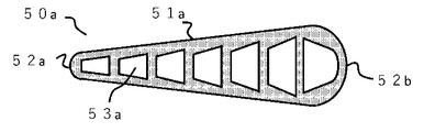
図15は本実施の形態における扁平管50aの断面形状を示す図である。扁平管50aの外形は扁平部51aと、先端部である小さい円形の曲面部52aと、後端部である大きい円形の曲面部52bと、から構成される。実施の形態1から3における扁平管50と比較すると、扁平管50aはその断面形状がテーパ状になっている点が異なる。また扁平管50aの断面形状は切り欠き部10cの形状と概同一である。
扁平管50aの内部には熱媒体(冷媒など)が流れる流路53aが成形されている。流路53aの形状は、扁平管50aのテーパ状の外形に合わせられており、扁平管50aの先端側で小さく、後端側では大きい台形となっている。なお、流路53aのうち最も後端側に位置するものは、他の流路53aと向きが逆で、底の片方が半円上になっている。このように流路53aを構成することで、流路53aの面積が大きくなり熱交換器100cの性能が向上する。
図16(a)から図16(c)は扁平管50aを切り欠き部10cに挿入する時の図である。図16(a)及び図16(b)は板状フィン1cに平行な平面から見た図であって、図16(a)は扁平管50aを切り欠き部10cに挿入する途中の図、図16(b)は扁平管50aを切り欠き部10cに挿入した状態の図である。なお、図16(a)及び図16(b)の線F-F’及び線G-G’は、図14(a)に示す線F-F’及び線G-G’と同一の位置の線である。また、図16(c)は扁平管50aを切り欠き部10cに挿入した状態での、線F-F’及び線G-G’における板状フィン1cの断面図である。
図16(a)に示す状態において、扁平管50aは切り欠き部10cの開口側から破線矢印の方向に移動する。このとき、切り欠き部10c及び扁平管50aの断面形状はテーパ状であるため、保持部14cと扁平管50aとは、扁平管50aの先端部が切り欠き部10cの先端部12に到達する寸前まで接触することがない。したがって、扁平管50aを切り欠き部10cに挿入するときに必要な力が小さくなる。
図16(b)に示すように、扁平管50aが切り欠き部10cに挿入されると、延伸部11から立設される保持部14cが扁平管50aを左右から挟みこみ、扁平管50aを保持する。これにより、扁平管50aが切り欠き部10cから脱落する、あるいは切り欠き部10cに対して位置ずれを起こすなどの虞が少ない。
図16(c)は扁平管50aが切り欠き部10cに挿入された後の、線F-F’及び線G-G’での板状フィン1cの断面を示している。ここで切り欠き部10cと、扁平管50aの断面形状とは概一致しているため、断面F-F’及び断面G-G’の両方で、扁平管50aは保持部14cを左右に押し広げた状態となっている。
熱交換器の製造方法
続いて、本実施の形態における熱交換器100cの製造方法について説明する。以下では、実施の形態3の熱交換器100bの製造方法と比較して、異なる部分を中心に説明する。説明を省略した部分については実施の形態3と同様である。
続いて、本実施の形態における熱交換器100cの製造方法について説明する。以下では、実施の形態3の熱交換器100bの製造方法と比較して、異なる部分を中心に説明する。説明を省略した部分については実施の形態3と同様である。
まず板状フィン1cの素材であるロウ材が塗布された金属板材に、切り欠き加工あるいはプレス加工などにより仮切り欠き部を成形する(工程1)。仮切り欠き部は切り欠き部10cと同様テーパ状であるが、その大きさは切り欠き部10cより小さい。また工程1では、次工程で成形される切り欠き部10cの延伸部11と、先端部12との境目に切り込みを入れる。
続いて、仮切り欠き部の周縁部に沿って曲げ加工などを施し、保持部14c及びフィンカラー13を成形する(工程2)。このとき仮切り欠き部が拡大し、切り欠き部10cが成形される。
以上のように成形された複数の板状フィン1cを、切り欠き部10cの開口部が鉛直上方になるよう装置に固定し、扁平管50aを挿入する(工程3)。扁平管50aが保持部14cに挿入させると、扁平管50aは保持部14cを外側に押し広げた状態となる。このようにして熱交換器100cは仮組みされる。
続いて仮組みされた熱交換器は、切り欠き部10cの開口側が鉛直下方になるよう配置され(工程4)、電気炉などの加熱装置に投入されロウ付けされる(工程5)。さらに、ロウ付け済みの仮組された熱交換器は、加熱装置から取り出され冷却される(工程6)。以上の工程を経て、熱交換器100cが製造される。
以上説明した熱交換器100cは、実施の形態3の熱交換器100bの効果に加えて以下の効果を奏する。切り欠き部10cの形状と、扁平管50aの断面形状とは概一致するテーパ状であるため、扁平管50aが切り欠き部10cに完全に挿入される寸前まで、扁平管50aと保持部14cとは接触することがない。したがって、小さい力で扁平管50aを切り欠き部10cに挿入することができる。
なお本実施の形態における、熱交換器100cの技術的な特徴である保持部14cの存在は、実施の形態3における保持部14bの確認方法と同じ方法で確認される。すなわち、扁平管50aの扁平部51aに擦過の形跡があること、延伸部11から立設される保持部14cと、先端部12から立設されるフィンカラー13との間に切り込みがあること、などにより保持部14cの存在が確認される。
本開示は、熱交換器に適用される。
1~1c 板状フィン、10~10c 切り欠き部、11 延伸部、12 先端部、
13 フィンカラー、14~14c 保持部、 15 誘導部、 16 スペーシングタブ
50~50a 扁平管、 51~51a 扁平部、 52~52b 曲面部、
53~53a 流路、 100~100c 熱交換器
13 フィンカラー、14~14c 保持部、 15 誘導部、 16 スペーシングタブ
50~50a 扁平管、 51~51a 扁平部、 52~52b 曲面部、
53~53a 流路、 100~100c 熱交換器
Claims (14)
- 扁平状熱交換管と、
前記扁平状熱交換管が挿入されるフィンであって、
前記扁平状熱交換管が挿入される切り欠き部と、
前記切り欠き部に設けられ、前記切り欠き部の内側に向けて突出し、前記扁平状熱交換管が前記切り欠き部に挿入された状態において、前記扁平状熱交換管に接触して、前記扁平状熱交換管の前記切り欠き部への挿入方向と逆方向の移動を妨げる保持部と、
を備えるフィンと、
を備える熱交換器。
- 前記切り欠き部は、対向する一対の延伸部と前記一対の延伸部に接続される先端部と、を有し、
前記保持部は前記延伸部に配置されている
請求項1に記載の熱交換器。
- 前記保持部は前記延伸部において、前記切り欠き部の開口端部から前記先端部までの中間より前記先端部側に配置されている
請求項2に記載の熱交換器。
- 前記保持部は互いに対向し、かつ、前記対向する保持部の間の距離は、前記一対の延伸部同士の間の距離よりも短い
請求項2または3に記載の熱交換器。
- 前記切り欠き部に前記扁平状熱交換管が挿入される前の状態において、前記保持部の間の距離が、前記扁平状熱交換管の幅よりも小さい
請求項4に記載の熱交換器。
- 前記一対の延伸部から立設し、前記扁平状熱交換管を支えるフィンカラー
を備える請求項2から5のいずれか一項に記載の熱交換器。
- 前記保持部は、周縁に曲線部分を有し、
前記扁平状熱交換管が前記切り欠き部に挿入された状態において、前記保持部の曲線部分は、前記扁平状熱交換管の前記挿入方向において、前記扁平状熱交換管の端部に位置する曲面部と接触する
請求項4から6のいずれか一項に記載の熱交換器。
- 前記保持部は、
前記対向する一対の延伸部全体から立設している
請求項2、4、5のいずれか一項に記載の熱交換器。
- 前記扁平状熱交換管の断面形状はテーパ状であり、
前記切り欠き部の形状は、前記テーパ状の扁平状熱交換管の断面形状と概同一のテーパ状である
ことを特徴とする請求項8に記載の熱交換器。
- 前記フィンはばね材料で作成される
請求項1から9のいずれか一項に記載の熱交換器。
- 前記フィンには、前記フィンから立設し、先端部が折り曲げられた鉤状のスペーシングタブが設けられている
請求項1から10のいずれか一項に記載の熱交換器。
- 前記フィンには、前記フィンの面に対する凹凸により、前記熱交換器を流れる気流に乱流を発生させる乱流促進部が設けられている
請求項1から11のいずれか一項に記載の熱交換器。
- 前記先端部には、前記フィンに塗布されたロウ材の加熱溶解時に、前記ロウ材を誘導する誘導部が設けられる
請求項2から12のいずれか一項に記載の熱交換器。
- 扁平状熱交換管と、前記扁平状熱交換管が挿入されるフィンと、を備える熱交換器の製造方法であって、
前記フィンに、仮の切り欠き部と、前記仮の切り欠き部の内側に突出する保持部を成形する工程と、
前記仮の切り欠き部を拡大して、前記扁平状熱交換管を挿入するための切り欠き部を成形する工程と、
前記切り欠き部に前記扁平状熱交換管を挿入し、前記扁平管熱交換管に前記保持部を接触させて、前記扁平状熱交換管の前記切り欠き部への挿入方向と逆方向への移動を妨げる工程と、
を備える熱交換器の製造方法。
Priority Applications (2)
| Application Number | Priority Date | Filing Date | Title |
|---|---|---|---|
| PCT/JP2021/019184 WO2022244196A1 (ja) | 2021-05-20 | 2021-05-20 | 熱交換器 |
| JP2023522126A JPWO2022244196A5 (ja) | 2021-05-20 | 熱交換器、および熱交換器の製造方法 |
Applications Claiming Priority (1)
| Application Number | Priority Date | Filing Date | Title |
|---|---|---|---|
| PCT/JP2021/019184 WO2022244196A1 (ja) | 2021-05-20 | 2021-05-20 | 熱交換器 |
Publications (1)
| Publication Number | Publication Date |
|---|---|
| WO2022244196A1 true WO2022244196A1 (ja) | 2022-11-24 |
Family
ID=84141158
Family Applications (1)
| Application Number | Title | Priority Date | Filing Date |
|---|---|---|---|
| PCT/JP2021/019184 Ceased WO2022244196A1 (ja) | 2021-05-20 | 2021-05-20 | 熱交換器 |
Country Status (1)
| Country | Link |
|---|---|
| WO (1) | WO2022244196A1 (ja) |
Citations (8)
| Publication number | Priority date | Publication date | Assignee | Title |
|---|---|---|---|---|
| JPH03128167A (ja) * | 1989-10-13 | 1991-05-31 | Matsushita Refrig Co Ltd | 熱交換器の製造方法 |
| JPH0560482A (ja) * | 1991-08-29 | 1993-03-09 | Showa Alum Corp | 熱交換器の製造方法 |
| JP2006010288A (ja) * | 2004-06-29 | 2006-01-12 | Denso Corp | 熱交換器 |
| JP2006220364A (ja) * | 2005-02-10 | 2006-08-24 | Denso Corp | 熱交換器 |
| EP2725311A2 (en) * | 2012-10-29 | 2014-04-30 | Samsung Electronics Co., Ltd | Heat exchanger |
| WO2014192771A1 (ja) * | 2013-05-27 | 2014-12-04 | 三菱電機株式会社 | 熱交換器の製造方法及び冷凍サイクル装置 |
| JP2019158215A (ja) * | 2018-03-12 | 2019-09-19 | 日立ジョンソンコントロールズ空調株式会社 | 空気調和機及び熱交換器 |
| WO2020062722A1 (zh) * | 2018-09-30 | 2020-04-02 | 珠海格力电器股份有限公司 | 一种翅片及具有其的热交换器 |
-
2021
- 2021-05-20 WO PCT/JP2021/019184 patent/WO2022244196A1/ja not_active Ceased
Patent Citations (8)
| Publication number | Priority date | Publication date | Assignee | Title |
|---|---|---|---|---|
| JPH03128167A (ja) * | 1989-10-13 | 1991-05-31 | Matsushita Refrig Co Ltd | 熱交換器の製造方法 |
| JPH0560482A (ja) * | 1991-08-29 | 1993-03-09 | Showa Alum Corp | 熱交換器の製造方法 |
| JP2006010288A (ja) * | 2004-06-29 | 2006-01-12 | Denso Corp | 熱交換器 |
| JP2006220364A (ja) * | 2005-02-10 | 2006-08-24 | Denso Corp | 熱交換器 |
| EP2725311A2 (en) * | 2012-10-29 | 2014-04-30 | Samsung Electronics Co., Ltd | Heat exchanger |
| WO2014192771A1 (ja) * | 2013-05-27 | 2014-12-04 | 三菱電機株式会社 | 熱交換器の製造方法及び冷凍サイクル装置 |
| JP2019158215A (ja) * | 2018-03-12 | 2019-09-19 | 日立ジョンソンコントロールズ空調株式会社 | 空気調和機及び熱交換器 |
| WO2020062722A1 (zh) * | 2018-09-30 | 2020-04-02 | 珠海格力电器股份有限公司 | 一种翅片及具有其的热交换器 |
Also Published As
| Publication number | Publication date |
|---|---|
| JPWO2022244196A1 (ja) | 2022-11-24 |
Similar Documents
| Publication | Publication Date | Title |
|---|---|---|
| JP5140051B2 (ja) | 熱交換器および熱交換器用フィンとその製造方法 | |
| EP2871434B1 (en) | Heat exchanger and method of manufacturing the same | |
| KR102085716B1 (ko) | 열 교환기 및 그 제조 방법 | |
| JPH0731030B2 (ja) | 熱交換器用ヘッダ−パイプの仕切板組付構造及び組付方法 | |
| US20180214963A1 (en) | Heat exchanger and method for producing same | |
| KR20140070012A (ko) | 열 교환기 및 그 제조 방법 | |
| JP2011127867A (ja) | 熱交換器用フィンおよび熱交換器とその製造方法 | |
| US20060175047A1 (en) | Heat exchanger, method of manufacturing heat exchanger and plate-shaped fin for heat exchanger | |
| CN110177990B (zh) | 热交换器的制造方法、热交换器的重叠方法、热交换器及多列热交换器 | |
| WO2022244196A1 (ja) | 熱交換器 | |
| JP2012172892A (ja) | フィン・アンド・チューブ型熱交換器 | |
| WO2020095797A1 (ja) | 熱交換器および熱交換器の製造方法 | |
| JPH1047888A (ja) | 熱交換器 | |
| JP2017198403A (ja) | 扁平管熱交換器およびその製造方法 | |
| US20250052519A1 (en) | Fins and heat exchanger comprising same | |
| JP2018151040A (ja) | 管継手、熱交換器及び熱交換器の製造方法 | |
| JP7742926B2 (ja) | ヘッダ管、熱交換器、空気調和装置及びヘッダ管の製造方法 | |
| JP2018159527A (ja) | 伝熱管、ヘッダ部材及び、熱交換器 | |
| JP6818601B2 (ja) | 熱交換器及び熱交換器の製造方法 | |
| JPH1038487A (ja) | 熱交換器の製造方法及び熱交換器 | |
| JP6616264B2 (ja) | 冷却器及びそれを備えた冷却装置 | |
| KR200365154Y1 (ko) | 휜앤 튜브형 열교환기 | |
| JP7258240B2 (ja) | 熱交換器用ヘッダ、熱交換器、及び熱交換器用ヘッダの製造方法 | |
| JP6632868B2 (ja) | アルミニウム製熱交換器 | |
| KR102793501B1 (ko) | 핀 및 이를 포함하는 열 교환기 |
Legal Events
| Date | Code | Title | Description |
|---|---|---|---|
| 121 | Ep: the epo has been informed by wipo that ep was designated in this application |
Ref document number: 21940810 Country of ref document: EP Kind code of ref document: A1 |
|
| WWE | Wipo information: entry into national phase |
Ref document number: 2023522126 Country of ref document: JP |
|
| NENP | Non-entry into the national phase |
Ref country code: DE |
|
| 122 | Ep: pct application non-entry in european phase |
Ref document number: 21940810 Country of ref document: EP Kind code of ref document: A1 |