WO2022244102A1 - 熱交換素子 - Google Patents
熱交換素子 Download PDFInfo
- Publication number
- WO2022244102A1 WO2022244102A1 PCT/JP2021/018789 JP2021018789W WO2022244102A1 WO 2022244102 A1 WO2022244102 A1 WO 2022244102A1 JP 2021018789 W JP2021018789 W JP 2021018789W WO 2022244102 A1 WO2022244102 A1 WO 2022244102A1
- Authority
- WO
- WIPO (PCT)
- Prior art keywords
- flow path
- heat transfer
- partial flow
- partial
- flow paths
- Prior art date
- Legal status (The legal status is an assumption and is not a legal conclusion. Google has not performed a legal analysis and makes no representation as to the accuracy of the status listed.)
- Ceased
Links
Images





Classifications
-
- F—MECHANICAL ENGINEERING; LIGHTING; HEATING; WEAPONS; BLASTING
- F28—HEAT EXCHANGE IN GENERAL
- F28D—HEAT-EXCHANGE APPARATUS, NOT PROVIDED FOR IN ANOTHER SUBCLASS, IN WHICH THE HEAT-EXCHANGE MEDIA DO NOT COME INTO DIRECT CONTACT
- F28D9/00—Heat-exchange apparatus having stationary plate-like or laminated conduit assemblies for both heat-exchange media, the media being in contact with different sides of a conduit wall
- F28D9/02—Heat-exchange apparatus having stationary plate-like or laminated conduit assemblies for both heat-exchange media, the media being in contact with different sides of a conduit wall the heat-exchange media travelling at an angle to one another
-
- F—MECHANICAL ENGINEERING; LIGHTING; HEATING; WEAPONS; BLASTING
- F28—HEAT EXCHANGE IN GENERAL
- F28F—DETAILS OF HEAT-EXCHANGE AND HEAT-TRANSFER APPARATUS, OF GENERAL APPLICATION
- F28F3/00—Plate-like or laminated elements; Assemblies of plate-like or laminated elements
- F28F3/02—Elements or assemblies thereof with means for increasing heat-transfer area, e.g. with fins, with recesses, with corrugations
- F28F3/04—Elements or assemblies thereof with means for increasing heat-transfer area, e.g. with fins, with recesses, with corrugations the means being integral with the element
-
- Y—GENERAL TAGGING OF NEW TECHNOLOGICAL DEVELOPMENTS; GENERAL TAGGING OF CROSS-SECTIONAL TECHNOLOGIES SPANNING OVER SEVERAL SECTIONS OF THE IPC; TECHNICAL SUBJECTS COVERED BY FORMER USPC CROSS-REFERENCE ART COLLECTIONS [XRACs] AND DIGESTS
- Y02—TECHNOLOGIES OR APPLICATIONS FOR MITIGATION OR ADAPTATION AGAINST CLIMATE CHANGE
- Y02B—CLIMATE CHANGE MITIGATION TECHNOLOGIES RELATED TO BUILDINGS, e.g. HOUSING, HOUSE APPLIANCES OR RELATED END-USER APPLICATIONS
- Y02B30/00—Energy efficient heating, ventilation or air conditioning [HVAC]
- Y02B30/56—Heat recovery units
Definitions
- the present disclosure relates to a heat exchange element that exchanges heat between two airflows.
- heat exchange elements have been used to ensure both good indoor air quality through ventilation and a comfortable thermal environment through air conditioning while suppressing the power consumption of air conditioners that perform air conditioning.
- the heat exchange element recovers sensible heat or total heat from the outdoor air by exchanging heat between the outdoor air taken in from the outside and the indoor air.
- the heat exchange element of Patent Literature 1 has a configuration in which first heat transfer plates and second heat transfer plates are alternately laminated, and first flow paths and second flow paths are alternately formed in the stacking direction.
- Each of the first heat transfer plate and the second heat transfer plate of the heat exchange element of Patent Document 1 has a corrugated portion formed in a corrugated shape when viewed in a cross section perpendicular to the flow path direction. In the corrugated portion, the corrugated shape is formed from one end to the other end in the flow path direction of the corrugated portion.
- the cross-sectional shape of the corrugated portion in the flow channel length direction is linear.
- the heat exchange element of Patent Document 1 extends outward from each of both ends of the corrugated portion in the flow path direction, and is inclined in the direction in which the height of the corrugation decreases from the vertex of the corrugation.
- the heat transfer performance is improved by having an inclined portion, which increases the heat exchange area, and by designing the angle of the inclined surface so that the air flow does not separate.
- the cross-sectional shape of the corrugated portion in the flow path length direction is linear, and the heat transfer performance is improved by forming inclined portions at both ends of the corrugated portion in the flow path direction.
- the present disclosure is intended to solve the above problems, and aims to obtain a heat exchange element capable of improving heat transfer performance.
- the heat exchange element according to the present disclosure is formed by alternately stacking the first heat transfer plate and the second heat transfer plate, and between the surface of the adjacent first heat transfer plate and the back surface of the second heat transfer plate
- the second heat transfer plate has a first central portion forming a first partial flow path and forming a plurality of second partial flow paths, and the second heat transfer plate forms a plurality of second partial flow paths and a plurality of first portions It has a second central portion forming a flow path, the first central portion and the second central portion overlap in the lamination direction of the first heat transfer plate and the second heat transfer plate, and
- the second central portion has a second wavy portion having a wavy cross-sectional shape in each of the channel width direction and the channel length direction, and the plurality of first wavy portions and the plurality of The wavy laminated portion, which is a laminated portion with the second wavy portion, has an airflow fluctuation portion for disturbing the airflow in the middle of part or all of the plurality of first partial flow passages and the plurality of second partial flow passages.
- the airflow fluctuation portion is formed by a portion of at least one of the first waveform portion and the second waveform portion being an inclined portion inclined in the stacking direction.
- the heat exchange element has the airflow fluctuation part in the middle of the first flow path and the second flow path, and the heat transfer performance can be improved by disturbing the airflow at the inclined part of the airflow fluctuation part.
- the cross-sectional shape in the direction of the flow path is not only wavy, but also in the direction of the flow path.
- the heat exchange area can be increased by increasing the heat transfer performance.
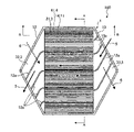
- FIG. 1 is a perspective view showing a heat exchange element according to Embodiment 1;
- FIG. 4 is a plan view of the first heat transfer plate of the heat exchange element according to Embodiment 1.
- FIG. 4 is a plan view of a second heat transfer plate of the heat exchange element according to Embodiment 1.
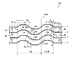
- FIG. 4 is a partial cross-sectional view of the heat exchange element taken along line AA shown in FIGS. 2 and 3;
- FIG. 5 is a partial cross-sectional view of the heat exchange element taken along line BB shown in FIG. 4;
- FIG. 5 is a diagram showing a modification of the heat exchange element according to Embodiment 1;
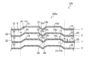
- FIG. 5 is a partial cross-sectional view along the line BB shown in FIG.
- FIG. 5 is a partial cross-sectional view along line BB shown in FIG. 4 of the heat exchange element according to Embodiment 3; 5 is a partial cross-sectional view along line BB shown in FIG. 4 of the heat exchange element according to Embodiment 4.
- FIG. 5 is a partial cross-sectional view along line BB shown in FIG. 4 of the heat exchange element according to Embodiment 4.
- FIG. 1 is a perspective view showing a heat exchange element 100 according to Embodiment 1.
- FIG. The heat exchange element 100 is formed in a hexagonal prism shape.
- the heat exchange element 100 is formed by alternately stacking the first heat transfer plates 1 and the second heat transfer plates 2 .
- the first heat transfer plate 1 and the second heat transfer plate 2 are formed using a resin sheet based on polypropylene, polystyrene, polyethylene terephthalate, or the like.
- a plurality of first flow paths 3 are formed in the plane direction.
- a plurality of second flow paths 4 are formed in the planar direction between the rear surface of the first heat transfer plate 1 and the surface of the second heat transfer plate 2 which are adjacent to each other.
- the first channel 3 has a first partial channel 31 , a fourth partial channel 33 and a third partial channel 32 .
- the second flow path 4 includes a second partial flow path 41 (see FIG. 3 described later), a fifth partial flow path 42 (see FIG. 3 described later), and a sixth partial flow path 43 (see FIG. 3 described later). and The details of the first channel 3 and the second channel 4 will be explained again.
- first air flow 5" the fluid flowing through the first flow path 3
- second air flow 6 the fluid flowing through the second flow path 4
- lamination direction the direction in which the first heat transfer plate 1 and the second heat transfer plate 2 are laminated
- flow path length direction the direction in which air flows in the first flow path 3 and the second flow path 4
- flow path width direction the width direction of the first flow path 3 and the second flow path 4
- FIG. 2 is a plan view of the first heat transfer plate 1 of the heat exchange element 100 according to Embodiment 1.
- FIG. FIG. 2 shows the surface side of the first heat transfer plate 1 .
- the first heat transfer plate 1 includes a first central portion 11 , a first header portion 12 connected to one end of the first central portion 11 along the flow path length direction, and a flow path portion of the first central portion 11 . and a second header portion 13 connected to the other end along the path length direction.
- Solid-line arrows in FIG. 2 indicate the flow of the first airflow 5 flowing on the surface of the first central portion 11 , the surface of the first header portion 12 , and the surface of the second header portion 13 .
- the dashed arrows shown in FIG. 2 indicate the flow of the second airflow 6 flowing on the rear surface of the first central portion 11 , the rear surface of the first header portion 12 , and the rear surface of the second header portion 13 .
- Each of the multiple first flow paths 3 has multiple first partial flow paths 31 , one fourth partial flow path 33 , and one third partial flow path 32 .
- the plurality of first partial flow paths 31 are flow paths in the central portion of the first flow path 3 .
- the fourth partial flow path 33 is a flow path on the upstream side of the plurality of first partial flow paths 31 and commonly communicates with the plurality of first partial flow paths 31 .
- the third partial flow path 32 is a flow path on the downstream side of the plurality of first partial flow paths 31 and commonly communicates with the plurality of first partial flow paths 31 .
- FIG. 1 shows an example in which there are four first flow paths 3, the present invention is not limited to this, and the number of first flow paths 3 is arbitrary.
- the first central portion 11 of the first heat transfer plate 1 forms a plurality of first partial flow paths 31 between the rear surface of the second central portion 21 described later of the second heat transfer plate 2 and the second central portion 11 of the second heat transfer plate 2. It is a portion that forms a plurality of second partial flow paths 41 with the surface of the portion 21 .
- the shape of the first central portion 11 when viewed from the stacking direction is rectangular. Also, part of the plurality of second partial flow paths 41 formed in the first central portion 11 constitutes the central portion of the second flow path 4 in the flow path length direction.
- the first central portion 11 has a first corrugated portion 14 having a corrugated shape in which crests and troughs are alternately formed continuously.
- the first header portion 12 is a portion that forms a plurality of third partial flow paths 32 between the second heat transfer plate 2 and the rear surface of a third header portion 22 described later.
- the shape of the first header portion 12 when viewed from the stacking direction is an isosceles triangle.
- the third partial flow path 32 is connected to one end of each of the plurality of first partial flow paths 31 forming the central portion of the first flow path 3 in the flow path length direction.
- a plurality of first channel ribs 12a are formed on the surface of the first header portion 12 at intervals.
- the first flow path rib 12a abuts on the back surface of the third header portion 22, which will be described later.
- a plurality of third partial flow paths 32 are formed by dividing the surface of the first header portion 12 and the back surface of the third header portion 22 by the first flow path ribs 12a. In FIG. 2, four third partial flow paths 32 are formed.
- the shortest first flow path rib 12a is provided in the lowermost third partial flow path 32 in FIG. It is ribs.
- the respective lengths of the plurality of third partial flow paths 32 are different from each other.
- the length of the plurality of third partial flow paths 32 is shorter from one end side to the other end side in the flow path width direction of the first central portion 11 .
- a plurality of the first central portion 11 is arranged from one end side (upper side in FIG. 2 ) toward the other end side (lower side in FIG. 2 ) in the flow path width direction (vertical direction in FIG. 2 ).
- the length of the three-part channel 32 is reduced.
- the second header portion 13 is a portion that forms a plurality of fourth partial flow paths 33 between the second heat transfer plate 2 and the rear surface of a fourth header portion 23 described later.
- the shape of the second header portion 13 when viewed from the stacking direction is an isosceles triangle shape.
- the fourth partial channel 33 is connected to the other end of each of the plurality of first partial channels 31 forming the central portion of the first channel 3 in the channel length direction.
- a plurality of second flow channel ribs 13a are formed on the surface of the second header portion 13 at intervals.
- the second flow path rib 13a abuts on the rear surface of the fourth header portion 23, which will be described later.
- a plurality of fourth partial flow paths 33 are formed by dividing the surface of the second header portion 13 and the back surface of the fourth header portion 23 by the second flow path ribs 13a. In FIG. 2, four fourth partial flow paths 33 are formed.
- the shortest second flow path rib 13a is provided in the uppermost fourth partial flow path 33 in FIG. It is ribs.
- the respective lengths of the plurality of fourth partial flow paths 33 are different from each other.
- the length of the plurality of fourth partial flow paths 33 is longer as it goes from one end side to the other end side in the flow path width direction of the first central portion 11 .
- a plurality of the first central portion 11 is arranged from one end side (upper side in FIG. 2 ) toward the other end side (lower side in FIG. 2 ) in the flow path width direction (vertical direction in FIG. 2 ).
- the length of the four-part flow path 33g is increased.
- the first channel rib 12 a and the second channel rib 13 a are inclined with respect to the channel length direction of the first partial channel 31 . Therefore, the third partial flow path 32 defined by the first flow path ribs 12 a and the fourth partial flow path 33 defined by the second flow path ribs 13 a are inclined with respect to the first partial flow path 31 .
- the first airflow 5 that has passed through the fourth partial flow path 33 flows obliquely into the plurality of first partial flow paths 31 and passes through the plurality of first partial flow paths 31 .
- the thus formed first airflow 5 flows obliquely to form a flow passing through the third partial flow path 32 .
- FIG. 3 is a plan view of the second heat transfer plate 2 of the heat exchange element 100 according to Embodiment 1.
- FIG. FIG. 3 shows the surface side of the second heat transfer plate 2 .
- the second heat transfer plate 2 includes a second central portion 21 , a third header portion 22 connected to one end of the second central portion 21 along the flow path length direction, and a fourth header portion 23 connected to the other end along the path length direction.
- Solid-line arrows in FIG. 3 indicate the flow of the second airflow 6 flowing on the surface of the second central portion 21 , the surface of the third header portion 22 , and the surface of the fourth header portion 23 .
- Broken line arrows shown in FIG. 3 indicate the flow of the first airflow 5 flowing on the back surface of the second central portion 21 , the back surface of the third header portion 22 , and the back surface of the fourth header portion 23 .
- the second channel 4 has a plurality of second partial channels 41 , one fifth partial channel 42 and one sixth partial channel 43 .
- a plurality of second partial flow paths 41 are flow paths in the central portion of the second flow path 4 .
- the fifth partial flow path 42 is a flow path on the upstream side of the plurality of second partial flow paths 41 and commonly communicates with the plurality of second partial flow paths 41 .
- the sixth partial flow path 43 is a flow path on the downstream side of the plurality of second partial flow paths 41 and commonly communicates with the plurality of second partial flow paths 41 .
- FIG. 1 shows an example in which there are four second flow paths 4 , the present invention is not limited to this, and the number of second flow paths 4 may be the same.
- the second central portion 21 of the second heat transfer plate 2 forms a plurality of second partial flow paths 41 between the back surface of the first central portion 11 of the first heat transfer plate 1 and the first central portion 11 It is a portion that forms a plurality of first partial flow paths 31 between the surface of the .
- the shape of the second central portion 21 when viewed from the stacking direction is rectangular.
- the second central portion 21 has a wave-shaped second wave portion 24 in which crests and troughs are alternately formed continuously.
- the flow direction of the first airflow 5 flowing through the first partial flow path 31 and the flow direction of the second airflow 6 flowing through the second partial flow path 41 differ by 180 degrees. That is, the flow direction of the first airflow 5 flowing through the first partial flow path 31 is opposite to the flow direction of the second airflow 6 flowing through the second partial flow path 41 .
- Heat is transferred between the first airflow 5 flowing through the first partial flow path 31 and the second airflow 6 flowing through the second partial flow path 41 .
- the heat exchange element 100 may be configured to transfer sensible heat and latent heat between air flows, or may be configured to transfer only sensible heat.
- the third header portion 22 is a portion that forms a plurality of fifth partial flow paths 42 between itself and the back surface of the first header portion 12 .
- the shape of the third header portion 22 when viewed from the stacking direction is an isosceles triangle shape.
- the fifth partial flow path 42 is connected to one end of each of the plurality of second partial flow paths 41 forming the central portion of the second flow path 4 in the flow direction.
- a plurality of third channel ribs 22a are formed on the surface of the third header portion 22 at intervals.
- the third flow path rib 22 a abuts on the back surface of the first header portion 12 .
- a plurality of fifth partial flow paths 42 are formed by dividing the surface of the third header portion 22 and the back surface of the first header portion 12 by the third flow path ribs 22a. In FIG. 3, four fifth partial channels 42 are formed.
- the shortest third flow path rib 22a is provided in the uppermost fifth partial flow path 42 in FIG. It is ribs.
- the lengths of the plurality of fifth partial flow paths 42 are different from each other.
- the lengths of the plurality of fifth partial flow paths 42 are longer from one end side to the other end side in the flow path width direction of the second central portion 21 .
- a plurality of the first central portion 11 is arranged from one end side (upper side in FIG. 3 ) toward the other end side (lower side in FIG. 3 ) in the flow path width direction (vertical direction in FIG. 3 ).
- the length of the five-part channel 42 is increased. As shown in FIGS. 2 and 3, the flow direction of the first airflow 5 flowing through the third partial flow path 32 and the flow direction of the second airflow 6 flowing through the fifth partial flow path 42 intersect.
- the fourth header portion 23 is a portion that forms a plurality of sixth partial flow paths 43 between itself and the back surface of the second header portion 13 .
- the shape of the fourth header portion 23 when viewed from the stacking direction is an isosceles triangle shape.
- the sixth partial channel 43 is connected to the other end of each of the plurality of second partial channels 41 forming the central portion of the second channel 4 in the channel length direction.
- a plurality of fourth flow channel ribs 23a are formed on the surface of the fourth header portion 23 at intervals.
- the fourth flow path rib 23 a abuts on the back surface of the second header portion 13 .
- a plurality of sixth partial flow paths 43 are formed by dividing the surface of the fourth header portion 23 and the back surface of the second header portion 13 by the fourth flow path ribs 23a. In FIG. 3, four sixth partial flow paths 43 are formed.
- the shortest fourth flow path rib 23a is provided in the lowermost sixth partial flow path 43 of the four sixth partial flow paths 43 in FIG. It is ribs.
- the respective lengths of the plurality of sixth partial flow paths 43 are different from each other.
- the length of the plurality of sixth partial flow paths 43 is shorter from one end side to the other end side in the flow path width direction of the second central portion 21 .
- a plurality of the second central portions 21 are arranged from one end side (upper side in FIG. 3 ) to the other end side (lower side in FIG. 3 ) in the flow path width direction (up-down direction in FIG. 3 ) of the second central portion 21 .
- the length of the 6-part channel 43 is shortened.
- the third channel rib 22 a and the fourth channel rib 23 a are inclined with respect to the channel length direction of the second partial channel 41 . Therefore, the fifth partial flow path 42 defined by the third flow path rib 22a and the sixth partial flow path 43 defined by the fourth flow path rib 23a are inclined with respect to the second partial flow path 41.
- the second airflow 6 that has passed through the fifth partial flow path 42 diagonally flows into the plurality of second partial flow paths 41 , and flows through the plurality of second partial flow paths 41 .
- the second airflow 6 that has passed through flows obliquely to form a flow that passes through the sixth partial flow path 43 .
- the flow direction of the first airflow 5 flowing through the fourth partial flow path 33 and the flow direction of the second airflow 6 flowing through the sixth partial flow path 43 intersect.
- the first airflow 5 that has passed through the plurality of first partial flow paths 31 passes through each third partial flow path 32 between the front surface of the first header portion 12 and the rear surface of the third header portion 22 to exchange heat. It flows out of the element 100 .
- the second airflow 6 that has passed through the plurality of second partial flow paths 41 passes through each of the sixth partial flow paths 43 between the rear surface of the second header portion 13 and the front surface of the fourth header portion 23 to exchange heat. It flows out of the element 100 .
- the first airflow 5 and the second airflow 6 flow so as to obliquely cross each other. Heat exchange takes place with stream 6 .
- the first airflow 5 and the second airflow 6 flow in opposite directions. Heat exchange takes place with the air stream 6 .
- the first airflow 5 and the second airflow 6 flow so as to obliquely intersect with each other. Heat exchange takes place with stream 6 .
- FIG. 4 is a partial cross-sectional view of the heat exchange element 100 taken along line AA shown in FIGS. 2 and 3.
- FIG. 4 When viewed in a cross section along the line AA in the width direction of the flow path, the first wave portion 14 has a convex portion that protrudes toward one side of the stacking direction and a convex portion that protrudes toward the other side of the stacking direction.
- the convex portions are formed alternately in the width direction of the flow path (horizontal direction in FIG. 4) to form a wavy shape.
- the first front-side flow paths 11a and the first back-side flow paths 11b are alternately formed in the width direction of the first wave portion 14 in the stacking direction.
- the first front-side channel 11a is part of the first partial channel 31 through which the first airflow 5 flows.
- the first back side channel 11b is part of the second partial channel 41 through which the second airflow 6 flows.
- the second wave portion 24 When viewed in cross section in the width direction of the flow path, the second wave portion 24 has a convex portion that protrudes toward one side of the stacking direction and a convex portion that protrudes toward the other side of the stacking direction in the width direction of the flow channel. It has a wavy shape formed alternately. As shown in FIG. 4, the second front-side flow paths 21a and the second back-side flow paths 21b are alternately formed in the width direction of the second wave portion 24 in the stacking direction.
- the second front-side channel 21a is part of the second partial channel 41 through which the second airflow 6 flows.
- the second back channel 21b is part of the first partial channel 31 through which the first airflow 5 flows.
- the first front-side flow paths 11a and the second front-side flow paths 21a are alternately arranged in the stacking direction.
- the first back side flow paths 11b and the second back side flow paths 21b are alternately arranged in the stacking direction.
- the above is the shape of the first waveform portion 14 and the second waveform portion 24 when viewed in cross section in the width direction of the flow path.
- the shapes of the first wave portion 14 and the second wave portion 24 when viewed in cross section in the flow channel length direction will be described.
- FIG. 5 is a partial cross-sectional view of heat exchange element 100 taken along line BB shown in FIG.
- the upper surface side is the front surface
- the lower surface side is the back surface.
- the dotted lines indicate the laminated portion of the first central portion 11 and the second central portion 21 , the laminated portion of the first header portion 12 and the third header portion 22 , the second header portion 13 and the fourth header portion 23 .
- a boundary portion with the laminated portion is shown.
- the first wavy portion 14 includes a first convex portion 14a that protrudes toward one side in the stacking direction and a first convex portion 14a that is convex in the other side in the stacking direction when viewed in a cross section along the line BB in the flow path length direction.
- the second protrusions 14b that protrude toward the channel are alternately formed in the length direction of the flow path (the left-right direction in FIG. 5) to form a wave shape.
- the top of each of the first convex portion 14a and the second convex portion 14b is a flat portion, and the upstream and downstream sides of the flat portion are inclined portions.
- the wavy shape of the first wavy portion 14 when viewed in the cross section in the flow channel length direction is compared to the wavy shape in the cross section in the flow channel width direction shown in FIG. It has a wide waveform shape.
- the second corrugated portion 24 has the same shape as the first corrugated portion 14 .
- the second wavy portion 24 includes a first convex portion 24a that protrudes in one direction in the stacking direction and a second convex portion 24b that protrudes in the other direction in the stacking direction when viewed in cross section in the flow channel length direction. are formed alternately in the lengthwise direction of the channel.
- the apex of each of the first convex portion 24a and the second convex portion 24b is a flat portion, and the upstream and downstream sides of the flat portion are inclined portions.
- the wavy shape of the second wavy portion 24 when viewed in the cross section in the flow channel length direction is larger than the wavy shape in the cross section in the flow channel width direction shown in FIG. It has a wide wavy shape.
- the first partial flow path 31 and the second partial flow path 41 which are formed by alternately laminating the first waveform portions 14 and the second waveform portions 24 having the above-described configuration, when viewed in cross section in the flow path length direction, It has a waveform flow path that is displaced in the stacking direction.
- the first partial flow path 31 and the second partial flow path 41 are flow paths in which inclined flow paths and straight flow paths are alternately connected in the flow path length direction.
- a layered portion in which the first wave portions 14 and the second wave portions 24 are alternately layered is referred to as a wave layered portion 100a.
- the corrugated laminated section 100a has an airflow fluctuation section 50 that disturbs the airflow in the middle of the flow path of the first partial flow path 31 .
- the airflow fluctuation portion 50 is formed by a portion of the first waveform portion 14 and a portion of the second waveform portion 24 forming an inclined portion inclined in the stacking direction.
- the airflow fluctuation section 50 is a flow passage portion between the surface of the inclined portion 15 inclined in the stacking direction in the first wave portion 14 and the back surface of the inclined portion 25 in the second wave portion 24 inclined in the stacking direction. be.
- the airflow fluctuation section 50 is an inclined channel portion that is inclined in one direction when viewed in a cross section in the length direction of the channel.
- the inclined portion 15 includes an inclined portion of the first convex portion 14a on the side of the second convex portion 14b and an inclined portion of the second convex portion 14b on the side of the first convex portion 14a.
- the inclined portion 25 includes an inclined portion of the first convex portion 24a on the side of the second convex portion 24b and an inclined portion of the second convex portion 24b on the side of the first convex portion 24a.
- the wave-laminated part 100a has an airflow fluctuation part 60 that disturbs the airflow in the middle of the flow path of the second partial flow path 41 .
- the airflow fluctuation portion 60 is formed by a portion of the first waveform portion 14 and a portion of the second waveform portion 24 forming an inclined portion inclined in the stacking direction.
- the airflow fluctuation part 60 is formed on the surface of the inclined portion 25 of the second waved portion 24 that is inclined in the stacking direction in the second waved portion 24, and the inclined portion 15 of the first waved portion 14 that is inclined in the stacking direction in the first waved portion 14. and the flow path portion between the back surface of the
- the airflow fluctuation part 60 is an inclined channel portion that is inclined in one direction when viewed in a cross section in the length direction of the channel.
- FIG. 5 is a cross-sectional view taken along the line BB in FIG. 4, and the cross-sectional shape of the portion where the first back side flow channel 11b and the second back side flow channel 21b are laminated has been described. The same applies to the cross-sectional shape of the portion where the path 11a and the second front side flow path 21a are laminated.
- the first airflow 5 passing through the first partial flow path 31 first passes through the flow path between the surface of the second convex portion 14b and the back surface of the second convex portion 24b, and It collides with the surface of the part 15 and is disturbed.
- the first airflow 5 disturbed by the airflow fluctuation portion 50 flows out from the first partial flow path 31 after passing through the flow path between the surface of the first convex portion 14a and the back surface of the first convex portion 24a. . Since the first airflow 5 is disturbed by the airflow fluctuation section 50 in this way, the temperature boundary layer developed in the upstream region of the airflow fluctuation section 50 is disturbed, and the heat transfer performance in the downstream region of the airflow fluctuation section 50 is reduced. is greatly improved, and the heat transfer performance in the first partial flow path 31 is improved.
- the second airflow 6 first passes through the flow path between the surface of the first convex portion 24a and the back surface of the first convex portion 14a, and then passes through the airflow fluctuation portion. It collides with the back surface of the inclined portion 15 of 60 and is disturbed.
- the second airflow 6 disturbed by the airflow fluctuation portion 60 flows out of the second partial flow path 41 after passing through the flow path between the surface of the second convex portion 24b and the back surface of the second convex portion 14b. .
- the heat exchange element 100 of the first embodiment has a wavy flow path structure when viewed in cross section in the flow path length direction, a large heat exchange area is ensured compared to the conventional linear structure. can do.
- the heat exchange element 100 can significantly improve both the heat transfer performance and the heat exchange area, which are the heat exchange performances, compared to the conventional structure. Therefore, the heat exchange element 100 can improve the heat transfer performance without increasing the mounting capacity or increasing the number of heat transfer plates.
- the flow direction of the first airflow 5 in the first partial flow path 31 is from right to left in FIG. 5, and the flow direction of the second airflow 6 passing through the second partial flow path 41 is shown in Although the left-to-right direction of 5 is shown as an example, it may be reversed.
- the flow directions of the first airflow 5 and the second airflow 6 are opposite to the directions shown in FIG. Airflow is disturbed.
- the airflow is disturbed by colliding with the surface of the inclined portion 25 of the airflow fluctuation section 60 .
- the wavy shape of the first wavy portion 14 and the second wavy portion 24 of the heat exchange element 100 when viewed in cross-section in the lengthwise direction of the flow path extends from one end to the other end without interruption in the flow direction of the flow path. continuous across. Therefore, in the heat exchange element 100, the first waveform portion 14 and the second waveform portion 24 are divided halfway in the flow direction of the flow channel, compared to a structure in which the waveform shape is interrupted in the flow direction of the flow channel. An increase in airflow resistance can be suppressed compared to a structure having a portion.
- a method for manufacturing the heat exchange element 100 includes a molding process, a trimming process, and a laminating process.
- the first heat transfer plate 1 is formed by vacuum forming, hot press forming, or the like.
- the 1st heat exchanger plate 1 the 1st center part 11, the 1st header part 12, and the 2nd header part 13 are integrally molded.
- the second heat transfer plate 2 is formed.
- the 2nd heat exchanger plate 2 the 2nd center part 21, the 3rd header part 22, and the 4th header part 23 are integrally molded.
- the trimming process unnecessary portions of the formed first heat transfer plate 1 and second heat transfer plate 2 are trimmed to adjust their outer shapes.
- the first heat transfer plate 1 and the second heat transfer plate 2 are alternately laminated.
- an air flow freely flows from the outside into the gap between the first heat transfer plates 1 and the second heat transfer plates 2. and pass through. Therefore, in order to form the flow of the first air flow 5 and the flow of the second air flow 6, necessary portions of the outer peripheral end portions of the first heat transfer plate 1 and the second heat transfer plate 2 are adjusted. need to be spliced.
- a joining process is performed to join such necessary portions.
- the first flow path 3 and the second flow path 4 that are independent of each other are formed in the heat exchange element 100, and the flow path is configured so that the first air flow 5 and the second air flow 6 do not mix. be done.
- a resin frame (not shown) is attached to each of the six corners of the heat exchange element 100 manufactured through the above steps.
- a sealant is filled between the heat exchange element 100 and the frame.
- the heat exchange element 100 of Embodiment 1 is formed by alternately laminating the first heat transfer plates 1 and the second heat transfer plates 2, and the surfaces of the adjacent first heat transfer plates 1 and the second heat transfer plates 2, and a plurality of second flow paths 4 are formed between the rear surface of the adjacent first heat transfer plate 1 and the surface of the second heat transfer plate 2. formed.
- Each of the plurality of first flow paths 3 has a plurality of first partial flow paths 31
- each of the plurality of second flow paths 4 has a plurality of second partial flow paths 41 .
- the first heat transfer plate 1 has a first central portion 11 forming a plurality of first partial passages 31 and a plurality of second partial passages 41 .
- the second heat transfer plate 2 has a second central portion 21 forming a plurality of second partial flow passages 41 and a plurality of first partial flow passages 31 .
- the first central portion 11 and the second central portion 21 overlap in the lamination direction of the first heat transfer plate 1 and the second heat transfer plate 2 .
- the first central portion 11 has a first wavy portion 14 having a wavy cross-sectional shape in each of the flow channel width direction and the flow channel length direction.
- the second central portion 21 has a second wavy portion 24 having a wavy cross-sectional shape in each of the flow channel width direction and the flow channel length direction.
- a wavy laminated portion 100a which is a lamination portion of the plurality of first wavy portions 14 and the plurality of second wavy portions 24, is part or all of the plurality of first partial flow passages 31 and the plurality of second partial flow passages 41.
- Airflow fluctuation units 50 and 60 for disturbing the airflow are provided on the way.
- the airflow fluctuation portions 50 and 60 are formed by forming inclined portions 15 and 25 in which a part of at least one of the first waveform portion 14 and the second waveform portion 24 is inclined in the stacking direction.
- the heat exchange element 100 has the airflow fluctuation sections 50 and 60 for disturbing the airflow in the middle of the first flow path 3 and the second flow path 4, so that the heat transfer performance can be improved.
- the first corrugated portion 14 of the first heat transfer plate 1 and the second corrugated portion 24 of the second heat transfer plate 2 are arranged in a cross section not only in the width direction of the flow channel but also in the length direction of the flow channel.
- the cross-sectional shape when viewed is also a wavy shape. Therefore, the heat exchange element 100 can increase the heat exchange area without changing the area when the heat exchange element 100 is viewed two-dimensionally, and can improve the heat transfer performance.
- the heat exchange element 100 can improve the heat transfer performance without enlarging the area of the heat transfer plate or increasing the number of the heat transfer plates.
- the heat exchange element 100 configured as described above is provided in a heat exchange ventilator, the same effect can be obtained for the heat exchange ventilator.
- heat exchange element 100 is not limited to the structure shown in FIG. 1, and can be modified, for example, as follows without departing from the gist of the present disclosure.
- FIG. 6 is a diagram showing a modification of the heat exchange element 100 according to Embodiment 1.
- the first wavy portion 14 and the second wavy portion 24 are composed of the first convex portion 14a that protrudes toward one side of the stacking direction and the other side of the stacking direction when viewed in cross section in the flow path length direction.
- 2nd convex part 14b which becomes convex toward 2nd convex part 14b becomes the waveform formed alternately in the flow-path width direction.
- a set of the first convex portion 14a convex in one stacking direction and the second convex portion 14b convex in the other stacking direction is one wave, FIG.
- each of the first waveform portion 14 and the second waveform portion 24 may have a waveform shape of 1.5 waves.
- each of the first waveform portion 14 and the second waveform portion 24 may be 0.5 wave (half wave), or may be two or more waves.
- the same effects as in the case where the first waveform portion 14 and the second waveform portion 24 have one waveform shown in FIG. 5 can be obtained. That is, when the first airflow 5 passes through the first partial flow passage 31, the airflow is disturbed by the airflow fluctuation section 50, thereby improving the heat transfer performance, and the second airflow 6 flows through the second partial flow passage. The airflow is disturbed by the airflow fluctuation section 60 when passing through 41, thereby improving the heat transfer performance.
- the position of the airflow fluctuation section on the upstream side of the two airflow fluctuation sections is located on the upstream side compared to the configuration of FIG. there is If the fluctuating airflow section is located on the upstream side of the flow path rather than on the downstream side, the effect of improving the heat transfer performance due to the turbulence of the airflow by the fluctuating airflow section can be obtained. This is because when the airflow fluctuation section is relatively upstream in the flow path, the airflow is disturbed and the subsequent flow path becomes longer. Therefore, from this point of view as well, the structure of FIG. 6 can be expected to have improved heat transfer performance compared to the structure of FIG.
- Embodiment 2 differs from Embodiment 1 in the shape of the inclined portion that constitutes the airflow fluctuation portion.
- the second embodiment will be described with a focus on the configuration different from the first embodiment, and the configurations not described in the second embodiment are the same as those in the first embodiment.
- FIG. 7 is a partial cross-sectional view along the line BB shown in FIG. 4 of the heat exchange element 100 according to the second embodiment.
- each of the first waveform portion 14 and the second waveform portion 24 has a single waveform shape when viewed in cross section in the flow path length direction.
- each of the first wavy portion 14 and the second wavy portion 24 has a half-wavy shape, that is, only the first convex portions 14a and 24a that protrude in one direction in the stacking direction.
- the flat portions of the first convex portions 14a and 24a have airflow fluctuation portions 50 and 60, respectively.
- the inclined portion 15 constituting the airflow fluctuation portion 50 has a first inclined portion 15a inclined in the stacking direction and a second inclined portion 15b inclined in the direction opposite to the first inclined portion 15a.
- the inclined portion 15 forms a V-shaped portion in which a first inclined portion 15a and a second inclined portion 15b are adjacent to each other in the flow channel length direction.
- the inclined portion 15 is provided on the flat portion of the first convex portion 14a.
- the inclined portion 25 constituting the airflow fluctuation portion 60 has a first inclined portion 25a inclined in the stacking direction and a second inclined portion 25b inclined in the direction opposite to the first inclined portion 25a.
- the inclined portion 25 forms a V-shaped portion in which a first inclined portion 25a and a second inclined portion 25b are adjacent to each other in the flow channel length direction.
- the inclined portion 25 is provided on the flat portion of the first convex portion 24a.
- the inclined portion 15 and the inclined portion 25 have the same shape and the same position in the width direction of the flow path. Therefore, the flow path shape of the first partial flow path 31 and the flow path shape of the second partial flow path 41 are the same when viewed in cross section in the flow path length direction.
- the position in the stacking direction of the top of the inclined portion 15 of the first corrugated portion 14 may be the same as the position in the stacking direction of the first header portion 12 and the second header portion 13 as shown in FIG. 7, or may be different. good too.
- the position of the top of the inclined portion 25 of the second corrugated portion 24 in the stacking direction may be the same as the position in the stacking direction of the third header portion 22 and the fourth header portion 23 as shown in FIG. may be The more the position of the stacking direction of the top of each of the inclined portions 15 and 25 is toward the inside of the flow path with which the back surface of the top is in contact, the more the amount of air that collides with the inclined portion. Increased performance is obtained.
- the positions of the apexes of the inclined portion 15 and the inclined portion 25 in the stacking direction may be appropriately set in consideration of this point.
- the airflow is turbulent by colliding with the back surface of the second inclined section 25b of the airflow fluctuation section 50. be done.
- the first airflow 5 disturbed by the airflow fluctuation section 50 flows out of the first partial flowpath 31 after passing through the flowpath downstream of the airflow fluctuation section 50 . Since the first airflow 5 is disturbed by the airflow fluctuation section 50 in this way, the temperature boundary layer developed in the upstream region of the airflow fluctuation section 50 is disturbed, and the heat transfer performance in the downstream region of the airflow fluctuation section 50 is reduced. is greatly improved, and the heat transfer performance in the first partial flow path 31 is improved.
- the airflow is turbulent by colliding with the rear surface of the first inclined section 15a of the airflow fluctuation section 60. be done.
- the second airflow 6 disturbed by the airflow fluctuation section 60 flows out of the second partial flowpath 41 after passing through the flowpath downstream of the airflow fluctuation section 60 .
- the temperature boundary layer developed in the upstream region of the airflow fluctuation section 60 is disturbed, and the heat transfer performance in the downstream region of the airflow fluctuation section 60 is reduced. is greatly improved, and the heat transfer performance in the second partial flow path 41 is improved.
- each of the first wavy portion 14 and the second wavy portion 24 has the shape of only the first protrusions 14a and 24a that protrude in one direction in the stacking direction. Therefore, the first partial flow path 31 and the second partial flow path 41 are substantially entirely straight flow paths when viewed in a cross section in the length direction of the flow path, and the straight flow path is formed with a V-shaped portion. Airflow fluctuation sections 50 and 60 are configured by the inclined sections 15 and 25 . Therefore, as in Embodiment 1, the channel structure in which the inclined channel, the straight channel, and the inclined channel are repeated in the channel length direction when viewed in the cross section in the channel length direction is compared. flow path fluctuation is small. Therefore, the heat exchange element 100 of the second embodiment can reduce the airflow resistance as compared with the first embodiment, and can further improve the heat transfer performance.
- FIG. 6 shows a configuration in which one airflow fluctuation unit 50 and one airflow fluctuation unit 60 are provided in each flow path, there may be a plurality of airflow fluctuation units 50 and 60 as in the modification of the first embodiment.
- the heat exchange element 100 of Embodiment 2 can obtain the same effects as those of the heat exchange element 100 of Embodiment 1, and also obtain the following effects. That is, the heat exchange element 100 of the second embodiment can reduce the airflow resistance compared to the first embodiment by having the above configuration, and can further improve the heat transfer performance. As a result, the heat exchange element 100 of Embodiment 2 can improve the heat transfer performance without increasing the mounting capacity or increasing the number of heat transfer plates.
- the heat exchange element 100 configured as described above is provided in a heat exchange ventilator, the same effect can be obtained for the heat exchange ventilator.
- Embodiment 3 differs from Embodiments 1 and 2 in the shape of the inclined portion that constitutes the airflow fluctuation portion.
- the following description will focus on the configuration of the third embodiment that differs from the first and second embodiments, and the configurations not described in the second embodiment are the same as those of the first and second embodiments. be.
- FIG. 8 is a partial cross-sectional view along the line BB shown in FIG. 4 of the heat exchange element 100 according to the third embodiment.
- the wall surface portions forming the airflow fluctuation portion 50 and the airflow fluctuation portion 60 in the first waveform portion 14 and the second waveform portion 24, that is, the inclined portion 15 and the inclined portion 25 are curved. It is configured.
- FIG. 8 shows an example in which the above configuration is applied to the configuration of Embodiment 1 shown in FIG. 5, it is not limited to this.
- the configuration of the third embodiment may be applied to part or all of the inclined portion 15 and the inclined portion 25 in the configuration of the second embodiment.
- the heat exchange element 100 of the third embodiment has the same effects as the heat exchange elements 100 of the first and second embodiments, and the above configuration allows the airflow to pass through the airflow fluctuation portion. It is possible to suppress an increase in pressure loss during passage. As a result, the heat exchange element 100 can further improve heat transfer performance while suppressing an increase in pressure loss without increasing the mounting capacity and the number of heat transfer plates.
- the heat exchange element 100 configured as described above is provided in a heat exchange ventilator, the same effect can be obtained for the heat exchange ventilator.
- Embodiment 4 In Embodiments 1 to 3, the channel shape of the first partial channel 31 and the channel shape of the second partial channel 41 are the same. In Embodiment 4, the channel shapes of the first partial channel 31 and the second partial channel 41 are different.
- FIG. 9 is a partial cross-sectional view along the line BB shown in FIG. 4 of the heat exchange element 100 according to the fourth embodiment.
- each of the first wavy portion 14 and the second wavy portion 24 has a semi-wavy shape, that is, only the first convex portions 14a and 24a that protrude in one direction in the stacking direction. Shape.
- the flat portion of the first waveform portion 14 is formed with the inclined portion 15 similar to that of the second embodiment, and the flat portion of the second waveform portion 24 is not formed with the inclined portion 25 .
- an airflow variation section 50 is formed between the surface of the slanted portion 15 of the first wavy portion 14 and the back surface portion of the second wavy portion 24 facing the slanted portion 15 .
- an air flow variation portion 60 is formed between the back surface of the inclined portion 15 of the first waveform portion 14 and the surface portion of the second waveform portion 24 facing the inclined portion 15 .
- the number of inclined portions 15 of the first corrugated portion 14 is different from the number of inclined portions 25 of the second corrugated portion 24.
- the channel shape of the channel 31 and the channel shape of the second partial channel 41 are different.
- the first partial channel 31 the channel widens at the inclined portion 15
- the second partial channel 41 the channel narrows at the inclined portion 15 .
- the first partial flow path 31 and the second partial flow path 41 have different flow path shapes, and hence different ventilation resistances.
- the ventilation resistance is lower than that of 41.
- the second airflow 6 passes through the flow path upstream of the airflow fluctuation section 60, and then collides with the back surface of the second inclined portion 15b of the airflow fluctuation section 60, thereby causing the airflow to change. Disturbed.
- the second airflow 6 disturbed by the airflow fluctuation section 60 flows out of the second partial flowpath 41 after passing through the flowpath downstream of the airflow fluctuation section 60 .
- the airflow is disturbed by the airflow fluctuation section 50 in the first partial flow path 31 to improve the heat transfer performance, and the airflow is disturbed by the airflow fluctuation section 60 in the second partial flow path 41 to improve the heat transfer performance.
- the cross-sectional area of the first partial flow path 31 is enlarged at the airflow fluctuation portion 50, the ventilation resistance is lower than that of the second partial flow path 41, and the air flows easily.
- the first partial flow path 31 and the second partial flow path 41 can have different airflow resistances, increasing the degree of freedom in design.
- the front and back surfaces of the first heat transfer plate 1 and the second heat transfer plate 2 are flow path forming surfaces that form flow paths, and dew condensation or freezing may occur on the flow path forming surfaces. Condensation or freezing on the flow path formation surface increases airflow resistance and reduces heat transfer capability. Therefore, by designing the flow path formation surface where condensation or freezing may occur to the flow path formation surface of the flow path with low ventilation resistance, the pressure loss during ventilation can be reduced and the heat transfer performance can be improved. can improve.
- first waveform portion 14 and the second waveform portion 24 have different numbers of inclined portions, so that the first partial flow path 31 and the second partial flow path 41 have different flow path shapes.
- it is not limited to this.
- the flow paths of the first partial flow path 31 and the second partial flow path 41 are changed. They may have different shapes.
- the sloped portion constituting the airflow fluctuation portion in the heat exchange element 100 is shown as an example of the sloped portion of the second embodiment shown in FIG. 7, that is, the V-shaped sloped portion. do not have.
- the inclined portion forming the airflow fluctuation portion may be the inclined portion in the first embodiment shown in FIG. 5 or the third embodiment shown in FIG.
- the heat exchange element 100 of the fourth embodiment has the same effects as those of the first to third embodiments, and also has the effect of increasing the degree of freedom in design due to the above configuration.
- the heat exchange element 100 configured as described above is provided in a heat exchange ventilator, the same effect can be obtained for the heat exchange ventilator.
- Embodiments 1 to 4 above are examples of the content of the present disclosure, and can be combined with other known techniques, and are within the scope of the present disclosure. It is also possible to omit or change part of the configuration.
Landscapes
- Engineering & Computer Science (AREA)
- Physics & Mathematics (AREA)
- Thermal Sciences (AREA)
- Mechanical Engineering (AREA)
- General Engineering & Computer Science (AREA)
- Heat-Exchange Devices With Radiators And Conduit Assemblies (AREA)
Abstract
熱交換素子は、第1伝熱板と第2伝熱板とが交互に積層されて形成され、隣接する第1伝熱板の表面と第2伝熱板の裏面との間に第1流路が複数形成されているとともに、隣接する第1伝熱板の裏面と第2伝熱板の表面との間に第2流路が複数形成されている。第1伝熱板の第1中央部は、流路幅方向および流路長さ方向のそれぞれの断面形状が波形形状の第1波形部を有する。第2伝熱板の第2中央部は、流路幅方向および流路長さ方向のそれぞれの断面形状が波形形状の第2波形部を有する。複数の第1波形部と複数の第2波形部との積層部分である波形積層部は、第1流路の複数の第1部分流路および第2流路の複数の第2部分流路の一部または全部の途中に、気流を乱すための気流変動部を有する。気流変動部は、第1波形部および第2波形部の少なくとも一方の一部が積層方向に傾斜した傾斜部となっていることにより形成されている。
Description
本開示は、2つの気流間で熱交換を行う熱交換素子に関するものである。
建物の室内において、人が在室している空間では、人体由来および建材由来等による空気を汚染する物質が放散される。このため、人の健康および快適性を確保する上で、換気扇等によって室内外の空気を置換し、室内の空気質を確保することが必須である。冷暖房による空調が必要な時期では、室内の空気質の確保に加えて空調機等による温熱環境の確保が重要となる。従来、換気による良質な室内の空気質と、空調による快適な温熱環境との両方を、空調を行う空調機の消費電力を抑えつつ確保するために、熱交換素子が用いられている。熱交換素子は、外部から取り込んだ室外空気と室内空気とを熱交換することで、室外空気から顕熱または全熱を回収するものである。換気に際し、熱交換素子を通して室外空気を室内に取り込むことで、冷暖房が必要な期間における空調機の消費電力の低減を図りつつ、室内の空気質を快適な状態に保つことを可能としている。
従来この種の熱交換素子として、たとえば特許文献1に開示された熱交換素子がある。特許文献1の熱交換素子は、第1伝熱板と第2伝熱板とが交互に積層されて積層方向に第1流路と第2流路とが交互に形成された構成を有する。特許文献1の熱交換素子の第1伝熱板および第2伝熱板のそれぞれは、流路方向に直交する断面で見て波形形状に形成された波形部を有する。波形部において波形形状は波形部の流路方向の一端から他端に渡って形成されている。波形部の流路長さ方向の断面形状は直線形状となっている。そして、特許文献1の熱交換素子は、波形部の流路方向の両端部に、その両端部のそれぞれから外方に延長し、かつ波形の頂点から波の高さが低くなる方向に傾斜した傾斜部を有し、この傾斜部により熱交換面積を増やすとともに傾斜面の角度を空気の流れが剥離しない角度に設計することで、伝熱性能の向上を図っている。
特許文献1の熱交換素子では、波形部の流路長さ方向の断面形状が直線形状であり、波形部の流路方向の両端部に傾斜部を形成することで伝熱性能の向上を図っているが、更なる伝熱性能の向上が求められている。
本開示は、上記のような問題点を解決するものであり、伝熱性能を向上することができる熱交換素子を得ることを目的とする。
本開示に係る熱交換素子は、第1伝熱板と第2伝熱板とが交互に積層されて形成され、隣接する第1伝熱板の表面と第2伝熱板の裏面との間に第1流路が複数形成されているとともに、隣接する第1伝熱板の裏面と第2伝熱板の表面との間に第2流路が複数形成されている熱交換素子であって、複数の第1流路のそれぞれは、第1部分流路を複数有し、複数の第2流路のそれぞれは、第2部分流路を複数有し、第1伝熱板は、複数の第1部分流路を形成するとともに複数の第2部分流路を形成する第1中央部を有し、第2伝熱板は、複数の第2部分流路を形成するとともに複数の第1部分流路を形成する第2中央部を有し、第1中央部と第2中央部とは第1伝熱板と第2伝熱板との積層方向で重なっており、第1流路および第2流路の幅方向を流路幅方向、空気が流れる方向を流路長さ方向というとき、第1中央部は、流路幅方向および流路長さ方向のそれぞれの断面形状が波形形状の第1波形部を有し、第2中央部は、流路幅方向および流路長さ方向のそれぞれの断面形状が波形形状の第2波形部を有し、複数の第1波形部と複数の第2波形部との積層部分である波形積層部は、複数の第1部分流路および複数の第2部分流路の一部または全部の途中に、気流を乱すための気流変動部を有し、気流変動部は、第1波形部および第2波形部の少なくとも一方の一部が積層方向に傾斜した傾斜部となっていることにより形成されているものである。
本開示によれば、熱交換素子は、第1流路および第2流路の途中に気流変動部を有し、気流変動部の傾斜部において気流が乱されることで伝熱性能を向上できる。また、流路幅方向の断面形状が波形形状であるだけでなく、流路方向の断面形状も波形形状であるため、熱交換素子は、流路方向の断面形状が直線状の構成と比較して熱交換面積を増やすことができ、伝熱性能を向上できる。
以下、本開示の実施の形態に係る熱交換素子について図面を参照しながら説明する。ここで、図1を含め、以下の図において、同一の符号を付したものは、同一またはこれに相当するものであり、以下に記載する実施の形態の全文において共通することとする。そして、明細書全文に表わされている構成要素の形態は、あくまでも例示であって、明細書に記載された形態に限定するものではない。特に構成要素の組み合わせは、各実施の形態における組み合わせのみに限定するものではなく、他の実施の形態に記載した構成要素を別の実施の形態に適用することができる。また、図面では各構成部材の大きさの関係が実際のものとは異なる場合がある。
実施の形態1.
<熱交換素子100の構成>
図1は、実施の形態1に係る熱交換素子100を示す斜視図である。
熱交換素子100は、六角柱状に形成されている。熱交換素子100は、第1伝熱板1と第2伝熱板2とが交互に積層されて形成されている。第1伝熱板1および第2伝熱板2は、ポリプロピレン、ポリスチレンまたはポリエチレンテレフタラートなどを基材とした樹脂シートを用いて形成されている。隣接する第1伝熱板1の表面と第2伝熱板2の裏面との間には、面方向に複数の第1流路3が形成されている。隣接する第1伝熱板1の裏面と第2伝熱板2の表面との間には、面方向に複数の第2流路4が形成されている。
<熱交換素子100の構成>
図1は、実施の形態1に係る熱交換素子100を示す斜視図である。
熱交換素子100は、六角柱状に形成されている。熱交換素子100は、第1伝熱板1と第2伝熱板2とが交互に積層されて形成されている。第1伝熱板1および第2伝熱板2は、ポリプロピレン、ポリスチレンまたはポリエチレンテレフタラートなどを基材とした樹脂シートを用いて形成されている。隣接する第1伝熱板1の表面と第2伝熱板2の裏面との間には、面方向に複数の第1流路3が形成されている。隣接する第1伝熱板1の裏面と第2伝熱板2の表面との間には、面方向に複数の第2流路4が形成されている。
第1流路3は、第1部分流路31と、第4部分流路33と、第3部分流路32とを有する。第2流路4は、第2部分流路41(後述の図3参照)と、第5部分流路42(後述の図3参照)と、第6部分流路43(後述の図3参照)とを有する。第1流路3および第2流路4の詳細については改めて説明する。
以下の説明では、第1流路3に流れる流体を「第1空気流5」と称し、第2流路4に流れる流体を「第2空気流6」と称する。また、第1伝熱板1と第2伝熱板2とが積層される方向を「積層方向」と称する。また、第1流路3および第2流路4において空気が流れる方向を「流路長さ方向」と称する。また、第1流路3および第2流路4の幅方向を「流路幅方向」と称する。
図2は、実施の形態1に係る熱交換素子100の第1伝熱板1の平面図である。図2には、第1伝熱板1の表面側を示している。第1伝熱板1は、第1中央部11と、第1中央部11のうち流路長さ方向に沿った一端に接続される第1ヘッダ部12と、第1中央部11のうち流路長さ方向に沿った他端に接続される第2ヘッダ部13とを有する。図2の実線矢印は、第1中央部11の表面、第1ヘッダ部12の表面および第2ヘッダ部13の表面を流れる第1空気流5の流れを示している。図2に示される破線矢印は、第1中央部11の裏面、第1ヘッダ部12の裏面および第2ヘッダ部13の裏面を流れる第2空気流6の流れを示している。
複数の第1流路3のそれぞれは、複数の第1部分流路31と、1つの第4部分流路33と、1つの第3部分流路32とを有する。複数の第1部分流路31は、第1流路3の中央部分の流路である。第4部分流路33は、複数の第1部分流路31の上流側の流路であって複数の第1部分流路31に共通に連通する流路である。第3部分流路32は、複数の第1部分流路31の下流側の流路であって複数の第1部分流路31に共通に連通する流路である。図1には第1流路3が4つある例を示しているが、これに限られたものではなく、第1流路3の数は任意である。
以下、第1流路3を形成する具体的な構造について説明する。
第1伝熱板1の第1中央部11は、第2伝熱板2の後記する第2中央部21の裏面との間に複数の第1部分流路31を形成するとともに、第2中央部21の表面との間に複数の第2部分流路41を形成する部分である。積層方向から見たときの第1中央部11の形状は、矩形状である。また、第1中央部11に形成された複数の第2部分流路41の一部によって第2流路4の流路長さ方向の中央部が構成されている。第1中央部11は、山と谷とが交互に連続して形成される波形形状の第1波形部14を有する。
第1ヘッダ部12は、第2伝熱板2の後記する第3ヘッダ部22の裏面との間に、複数の第3部分流路32を形成する部分である。積層方向から見たときの第1ヘッダ部12の形状は、二等辺三角形状である。第3部分流路32は、第1流路3の流路長さ方向の中央部を構成する複数の第1部分流路31のそれぞれの一端と接続されている。
第1ヘッダ部12の表面には、互いに間隔を空けて複数の第1流路リブ12aが形成されている。第1流路リブ12aは、後記する第3ヘッダ部22の裏面に当接する。第1ヘッダ部12の表面と第3ヘッダ部22の裏面との間が、第1流路リブ12aにより区画されることで、複数の第3部分流路32が形成されている。図2では、4つの第3部分流路32が形成されている。複数の第1流路リブ12aのうち、最も長さの短い第1流路リブ12aは、4つの第3部分流路32のうち図2の最も下の第3部分流路32内に設けられたリブである。複数の第3部分流路32のそれぞれの長さは、互いに異なっている。複数の第3部分流路32の長さは、第1中央部11の流路幅方向の一端側から他端側に向かうほど短い。図2の例では、第1中央部11の流路幅方向(図2の上下方向)の一端側(図2の上側)から他端側(図2の下側)に向かうほど、複数の第3部分流路32の長さが短くなっている。
第2ヘッダ部13は、第2伝熱板2の後記する第4ヘッダ部23の裏面との間に、複数の第4部分流路33を形成する部分である。積層方向から見たときの第2ヘッダ部13の形状は、二等辺三角形状である。第4部分流路33は、第1流路3の流路長さ方向の中央部を構成する複数の第1部分流路31のそれぞれの他端に接続されている。
第2ヘッダ部13の表面には、互いに間隔を空けて複数の第2流路リブ13aが形成されている。第2流路リブ13aは、後記する第4ヘッダ部23の裏面に当接する。第2ヘッダ部13の表面と第4ヘッダ部23の裏面との間が、第2流路リブ13aにより区画されることで、複数の第4部分流路33が形成されている。図2では、4つの第4部分流路33が形成されている。複数の第2流路リブ13aのうち、最も長さの短い第2流路リブ13aは、4つの第4部分流路33のうち図2の最も上の第4部分流路33内に設けられたリブである。複数の第4部分流路33のそれぞれの長さは、互いに異なっている。複数の第4部分流路33の長さは、第1中央部11の流路幅方向の一端側から他端側に向かうほど長い。図2の例では、第1中央部11の流路幅方向(図2の上下方向)の一端側(図2の上側)から他端側(図2の下側)に向かうほど、複数の第4部分流路33gの長さが長くなっている。
第1流路リブ12aと第2流路リブ13aとは、第1部分流路31の流路長さ方向に対して傾斜している。よって、第1流路リブ12aによって区画される第3部分流路32と第2流路リブ13aによって区画される第4部分流路33とは、第1部分流路31に対して傾斜している。これにより、第1流路3では、第4部分流路33を通過した第1空気流5が複数の第1部分流路31に斜め方向から流入し、複数の第1部分流路31を通過した第1空気流5は、斜め方向に流出して第3部分流路32を通過する流れが形成される。
図3は、実施の形態1に係る熱交換素子100の第2伝熱板2の平面図である。図3には、第2伝熱板2の表面側を示している。第2伝熱板2は、第2中央部21と、第2中央部21のうち流路長さ方向に沿った一端に接続される第3ヘッダ部22と、第2中央部21のうち流路長さ方向に沿った他端に接続される第4ヘッダ部23とを有する。図3の実線矢印は、第2中央部21の表面、第3ヘッダ部22の表面および第4ヘッダ部23の表面を流れる第2空気流6の流れを示している。図3に示される破線矢印は、第2中央部21の裏面、第3ヘッダ部22の裏面および第4ヘッダ部23の裏面を流れる第1空気流5の流れを示している。
第2流路4は、複数の第2部分流路41と、1つの第5部分流路42と、1つの第6部分流路43とを有する。複数の第2部分流路41は第2流路4の中央部分の流路である。第5部分流路42は、複数の第2部分流路41の上流側の流路であって複数の第2部分流路41に共通に連通する流路である。第6部分流路43は、複数の第2部分流路41の下流側の流路であって複数の第2部分流路41に共通に連通する流路である。図1には第2流路4が4つある例を示しているが、これに限られたものではなく、第2流路4と同数であればよい。
以下、第2流路4を形成する具体的な構造について説明する。
第2伝熱板2の第2中央部21は、第1伝熱板1の第1中央部11の裏面との間に複数の第2部分流路41を形成するとともに、第1中央部11の表面との間に複数の第1部分流路31を形成する部分である。積層方向から見たときの第2中央部21の形状は、矩形状である。第2中央部21は、山と谷とが交互に連続して形成される波形形状の第2波形部24を有する。
第1部分流路31を流れる第1空気流5の流れ方向と、第2部分流路41を流れる第2空気流6の流れ方向とは、180度異なっている。つまり、第1部分流路31を流れる第1空気流5の流れ方向と、第2部分流路41を流れる第2空気流6の流れ方向とは逆向きである。第1部分流路31を流れる第1空気流5と、第2部分流路41を流れる第2空気流6との間で熱が伝達される。なお、熱交換素子100は、空気流同士の間で、顕熱と潜熱とを伝達させる構成でもよいし、顕熱のみを伝達させる構成でもよい。
図3に示すように、第3ヘッダ部22は、第1ヘッダ部12の裏面との間に、複数の第5部分流路42を形成する部分である。積層方向から見たときの第3ヘッダ部22の形状は、二等辺三角形状である。第5部分流路42は、第2流路4の流路長さ方向の中央部を構成する複数の第2部分流路41のそれぞれの一端と接続されている。
第3ヘッダ部22の表面には、互いに間隔を空けて複数の第3流路リブ22aが形成されている。第3流路リブ22aは、第1ヘッダ部12の裏面に当接する。第3ヘッダ部22の表面と第1ヘッダ部12の裏面との間が、第3流路リブ22aにより区画されることで、複数の第5部分流路42が形成されている。図3では、4つの第5部分流路42が形成されている。複数の第3流路リブ22aのうち、最も長さの短い第3流路リブ22aは、4つの第5部分流路42のうち図3の最も上の第5部分流路42内に設けられたリブである。複数の第5部分流路42のそれぞれの長さは、互いに異なっている。複数の第5部分流路42の長さは、第2中央部21の流路幅方向の一端側から他端側に向かうほど長い。図3の例では、第1中央部11の流路幅方向(図3の上下方向)の一端側(図3の上側)から他端側(図3の下側)に向かうほど、複数の第5部分流路42の長さが長くなっている。図2および図3に示すように、第3部分流路32を流れる第1空気流5の流れ方向と、第5部分流路42を流れる第2空気流6の流れ方向とは、交差する。
図3に示すように、第4ヘッダ部23は、第2ヘッダ部13の裏面との間に、複数の第6部分流路43を形成する部分である。積層方向から見たときの第4ヘッダ部23の形状は、二等辺三角形状である。第6部分流路43は、第2流路4の流路長さ方向の中央部を構成する複数の第2部分流路41のそれぞれの他端と接続されている。
第4ヘッダ部23の表面には、互いに間隔を空けて複数の第4流路リブ23aが形成されている。第4流路リブ23aは、第2ヘッダ部13の裏面に当接する。第4ヘッダ部23の表面と第2ヘッダ部13の裏面との間が、第4流路リブ23aにより区画されることで複数の第6部分流路43が形成されている。図3では、4つの第6部分流路43が形成されている。複数の第4流路リブ23aのうち、最も長さの短い第4流路リブ23aは、4つの第6部分流路43のうち図3の最も下の第6部分流路43内に設けられたリブである。複数の第6部分流路43のそれぞれの長さは、互いに異なっている。複数の第6部分流路43の長さは、第2中央部21の流路幅方向の一端側から他端側に向かうほど短い。図3の例では、第2中央部21の流路幅方向(図3の上下方向)の一端側(図3の上側)から他端側(図3の下側)に向かうほど、複数の第6部分流路43の長さが短くなっている。
第3流路リブ22aと第4流路リブ23aとは、第2部分流路41の流路長さ方向に対して傾斜している。よって、第3流路リブ22aによって区画される第5部分流路42と第4流路リブ23aによって区画される第6部分流路43とは、第2部分流路41に対して傾斜している。これにより、第2流路4では、第5部分流路42を通過した第2空気流6が、複数の第2部分流路41に斜め方向から流入し、複数の第2部分流路41を通過した第2空気流6は、斜め方向に流出して第6部分流路43を通過する流れが形成される。図2および図3に示すように、第4部分流路33を流れる第1空気流5の流れ方向と、第6部分流路43を流れる第2空気流6の流れ方向とは、交差する。
<熱交換器の動作>
熱交換素子100において、第2ヘッダ部13の表面と第4ヘッダ部23の裏面との間の各第4部分流路33に外部から流入した第1空気流5は、各第4部分流路33を通過後、複数の第1部分流路31に流入する。複数の第1部分流路31を通過した第1空気流5は、第1ヘッダ部12の表面と第3ヘッダ部22の裏面との間の各第3部分流路32を通過して熱交換素子100から流出する。
熱交換素子100において、第2ヘッダ部13の表面と第4ヘッダ部23の裏面との間の各第4部分流路33に外部から流入した第1空気流5は、各第4部分流路33を通過後、複数の第1部分流路31に流入する。複数の第1部分流路31を通過した第1空気流5は、第1ヘッダ部12の表面と第3ヘッダ部22の裏面との間の各第3部分流路32を通過して熱交換素子100から流出する。
また、熱交換素子100において、第1ヘッダ部12の裏面と第3ヘッダ部22の表面との間の各第5部分流路42に外部から流入した第2空気流6は、各第5部分流路42を通過後、複数の第2部分流路41に流入する。複数の第2部分流路41を通過した第2空気流6は、第2ヘッダ部13の裏面と第4ヘッダ部23の表面との間の各第6部分流路43を通過して熱交換素子100から流出する。
第2ヘッダ部13および第4ヘッダ部23の積層部分では、第1空気流5と第2空気流6とがお互いに斜め方向に交差するようにして流れ、第1空気流5と第2空気流6との間で熱交換が行われる。
第1中央部11と第2中央部21との積層部分では、第1空気流5と第2空気流6とが逆方向に流れ、いわゆる対向流の流れにおいて、第1空気流5と第2空気流6との間で熱交換が行われる。
第1ヘッダ部12および第3ヘッダ部22の積層部分では、第1空気流5と第2空気流6とがお互いに斜め方向に交差するようにして流れ、第1空気流5と第2空気流6との間で熱交換が行われる。
<第1中央部11および第2中央部21の詳細な構成>
以下、第1中央部11の第1波形部14および第2中央部21の第2波形部24について図4を参照して詳しく説明する。
以下、第1中央部11の第1波形部14および第2中央部21の第2波形部24について図4を参照して詳しく説明する。
図4は、図2および図3に示されたA-A線に沿った熱交換素子100の部分断面図である。
第1波形部14は、A-A線に沿った断面である流路幅方向の断面で見たとき、積層方向の一方に向けて凸となる凸部と積層方向の他方に向けて凸となる凸部とが流路幅方向(図4の左右方向)に交互に形成された波形形状となっている。図4に示すように、第1波形部14の積層方向の長さの範囲には、第1表側流路11aと第1裏側流路11bとが流路幅方向に交互に形成されている。第1表側流路11aは、第1空気流5が流れる第1部分流路31の一部である。第1裏側流路11bは、第2空気流6が流れる第2部分流路41の一部である。
第1波形部14は、A-A線に沿った断面である流路幅方向の断面で見たとき、積層方向の一方に向けて凸となる凸部と積層方向の他方に向けて凸となる凸部とが流路幅方向(図4の左右方向)に交互に形成された波形形状となっている。図4に示すように、第1波形部14の積層方向の長さの範囲には、第1表側流路11aと第1裏側流路11bとが流路幅方向に交互に形成されている。第1表側流路11aは、第1空気流5が流れる第1部分流路31の一部である。第1裏側流路11bは、第2空気流6が流れる第2部分流路41の一部である。
第2波形部24は、流路幅方向の断面で見たとき、積層方向の一方に向けて凸となる凸部と積層方向の他方に向けて凸となる凸部とが流路幅方向に交互に形成された波形形状となっている。図4に示すように、第2波形部24の積層方向の長さの範囲には、第2表側流路21aと第2裏側流路21bとが流路幅方向に交互に形成されている。第2表側流路21aは、第2空気流6が流れる第2部分流路41の一部である。第2裏側流路21bは、第1空気流5が流れる第1部分流路31の一部である。
第1表側流路11aと第2表側流路21aとは、積層方向に交互に配置されている。第1裏側流路11bと第2裏側流路21bとは、積層方向に交互に配置されている。
以上は、第1波形部14および第2波形部24を流路幅方向の断面で見たときの形状である。以下、第1波形部14および第2波形部24を流路長さ方向の断面で見たときの形状について説明する。
図5は、図4に示されたB-B線に沿った熱交換素子100の部分断面図である。図5の第1伝熱板1および第2伝熱板2のそれぞれにおいて、上面側が表面、下面側が裏面である。図5において点線は、第1中央部11および第2中央部21の積層部分と、第1ヘッダ部12および第3ヘッダ部22の積層部分と、第2ヘッダ部13および第4ヘッダ部23の積層部分との境界部分を示している。
第1波形部14は、B-B線に沿った断面である流路長さ方向の断面で見たとき、積層方向の一方に向けて凸となる第1凸部14aと、積層方向の他方に向けて凸となる第2凸部14bとが流路長さ方向(図5の左右方向)に交互に形成された波形形状となっている。第1凸部14aおよび第2凸部14bのそれぞれの頂部は平坦部となっており、平坦部の上流側および下流側は傾斜部となっている。図5に示したように、流路長さ方向の断面で見たときの第1波形部14の波形形状は、図4に示した流路幅方向の断面で見たときの波形形状に比べて幅広の波形形状となっている。
第1波形部14は、B-B線に沿った断面である流路長さ方向の断面で見たとき、積層方向の一方に向けて凸となる第1凸部14aと、積層方向の他方に向けて凸となる第2凸部14bとが流路長さ方向(図5の左右方向)に交互に形成された波形形状となっている。第1凸部14aおよび第2凸部14bのそれぞれの頂部は平坦部となっており、平坦部の上流側および下流側は傾斜部となっている。図5に示したように、流路長さ方向の断面で見たときの第1波形部14の波形形状は、図4に示した流路幅方向の断面で見たときの波形形状に比べて幅広の波形形状となっている。
第2波形部24は、第1波形部14と同じ形状である。第2波形部24は、流路長さ方向の断面で見たとき、積層方向の一方に向けて凸となる第1凸部24aと積層方向の他方に向けて凸となる第2凸部24bとが流路長さ方向に交互に形成された波形形状となっている。第1凸部24aおよび第2凸部24bのそれぞれの頂部は平坦部となっており、平坦部の上流側および下流側は傾斜部となっている。図5に示したように、流路長さ方向の断面でみたときの第2波形部24の波形形状は、図4に示した流路幅方向の断面で見たときの波形形状に比べて幅広の波形形状となっている。
上記構成の第1波形部14と第2波形部24とが交互に積層されて形成された第1部分流路31および第2部分流路41は、流路長さ方向の断面で見て、積層方向に変位した波形流路となっている。つまり、第1部分流路31および第2部分流路41は、流路長さ方向に傾斜流路と直線流路とが交互に連なる流路となる。以下、第1波形部14と第2波形部24とが交互に積層された積層部分を波形積層部100aという。
波形積層部100aは、第1部分流路31の流路の途中に、気流を乱す気流変動部50を有する。気流変動部50は、第1波形部14の一部と第2波形部24の一部とが積層方向に傾斜した傾斜部となっていることにより形成されている。気流変動部50は、第1波形部14において積層方向に傾斜した傾斜部15の表面と、第2波形部24において積層方向に傾斜した傾斜部25の裏面と、との間の流路部分である。気流変動部50は、流路長さ方向の断面で見て一方向に傾斜する傾斜流路部分である。傾斜部15は、第1凸部14aの第2凸部14b側の傾斜部と、第2凸部14bの第1凸部14a側の傾斜部とを含んで構成される。傾斜部25は、第1凸部24aの第2凸部24b側の傾斜部と、第2凸部24bの第1凸部24a側の傾斜部とを含んで構成される。
また、波形積層部100aは、第2部分流路41の流路の途中に、気流を乱す気流変動部60を有する。気流変動部60は、第1波形部14の一部と第2波形部24の一部とが積層方向に傾斜した傾斜部となっていることにより形成されている。気流変動部60は、第2波形部24において積層方向に傾斜した第2波形部24の傾斜部25の表面と、第1波形部14において積層方向に傾斜した第1波形部14の傾斜部15の裏面と、の間の流路部分である。気流変動部60は、流路長さ方向の断面で見て一方向に傾斜する傾斜流路部分である。
なお、図5は図4のB-B線に沿った断面図であり、第1裏側流路11bと第2裏側流路21bとが積層する部分の断面形状について説明したが、第1表側流路11aと第2表側流路21aとが積層する部分の断面形状についても同様である。
<上記構成による作用効果>
第1部分流路31を通過する第1空気流5は、まず、第2凸部14bの表面と第2凸部24bの裏面との間の流路を通過した後、気流変動部50の傾斜部15の表面に衝突して乱される。気流変動部50で乱された第1空気流5は、第1凸部14aの表面と第1凸部24aの裏面との間の流路を通過した後、第1部分流路31から流出する。このように第1空気流5が気流変動部50で乱されることで、気流変動部50の上流の領域で発達した温度境界層が乱され、気流変動部50の下流の領域における伝熱性能が大幅に向上し、第1部分流路31における伝熱性能が向上する。
第1部分流路31を通過する第1空気流5は、まず、第2凸部14bの表面と第2凸部24bの裏面との間の流路を通過した後、気流変動部50の傾斜部15の表面に衝突して乱される。気流変動部50で乱された第1空気流5は、第1凸部14aの表面と第1凸部24aの裏面との間の流路を通過した後、第1部分流路31から流出する。このように第1空気流5が気流変動部50で乱されることで、気流変動部50の上流の領域で発達した温度境界層が乱され、気流変動部50の下流の領域における伝熱性能が大幅に向上し、第1部分流路31における伝熱性能が向上する。
第2部分流路41においても同様であり、第2空気流6は、まず、第1凸部24aの表面と第1凸部14aの裏面との間の流路を通過した後、気流変動部60の傾斜部15の裏面に衝突して乱される。気流変動部60で乱された第2空気流6は、第2凸部24bの表面と第2凸部14bの裏面との間の流路を通過した後、第2部分流路41から流出する。このように第2空気流6が気流変動部60で乱されることで、気流変動部60の上流の領域で発達した温度境界層が乱され、気流変動部60の下流の領域における伝熱性能が大幅に向上し、第2部分流路41における伝熱性能が向上する。
また、実施の形態1の熱交換素子100は、流路長さ方向の断面でみたときの流路構造が波形形状であるため、直線形状とした従来構造に比べて、熱交換面積を多く確保することができる。
以上より、熱交換素子100は、従来構造に比べて熱交換性能である伝熱性能と熱交換面積のそれぞれを大幅に向上することができる。したがって、熱交換素子100は、搭載容積を拡大したり、伝熱板の枚数を増加したりすることなく、伝熱性能を向上できる。
なお、ここでは、第1部分流路31における第1空気流5の流れ方向が図5の右から左方向であり、第2部分流路41を通過する第2空気流6の流れ方向が図5の左から右方向である例を示したが、逆としてもよい。第1空気流5および第2空気流6の流れ方向が図5に示した方向とは逆の場合、第1部分流路31では、気流変動部50の傾斜部25の裏面に衝突することで気流が乱される。また、第2部分流路41では、気流変動部60の傾斜部25の表面に衝突することで気流が乱される。
また、熱交換素子100の第1波形部14および第2波形部24を流路長さ方向の断面で見たときの波形形状は、流路流れ方向において途中で途切れることなく一端から他端に渡って連続している。このため、熱交換素子100は、波形形状が流路流れ方向において途中で途切れる構造と比較して、具体的には第1波形部14および第2波形部24が流路流れ方向の途中に分割部を有する構造と比較して、通風抵抗の増加を抑制することができる。
<製造方法>
次に、熱交換素子100の製造方法について説明する。熱交換素子100の製造方法は、成形工程と、トリム工程と、積層工程とを含む。成形工程では、真空成形または熱プレス成形などにより第1伝熱板1を成形する。第1伝熱板1は、第1中央部11、第1ヘッダ部12および第2ヘッダ部13が一体で成形される。また、成形工程では、第2伝熱板2を成形する。第2伝熱板2は、第2中央部21、第3ヘッダ部22および第4ヘッダ部23が一体で成形される。トリム工程では、成形された第1伝熱板1および第2伝熱板2の不要部分を削って、その外形を整える。
次に、熱交換素子100の製造方法について説明する。熱交換素子100の製造方法は、成形工程と、トリム工程と、積層工程とを含む。成形工程では、真空成形または熱プレス成形などにより第1伝熱板1を成形する。第1伝熱板1は、第1中央部11、第1ヘッダ部12および第2ヘッダ部13が一体で成形される。また、成形工程では、第2伝熱板2を成形する。第2伝熱板2は、第2中央部21、第3ヘッダ部22および第4ヘッダ部23が一体で成形される。トリム工程では、成形された第1伝熱板1および第2伝熱板2の不要部分を削って、その外形を整える。
積層工程では、第1伝熱板1と第2伝熱板2とを交互に積層する。第1伝熱板1と第2伝熱板2とを単に交互に積層した状態では、第1伝熱板1と第2伝熱板2との間の隙間に外方から自由に気流が流入して通過する状態である。よって、上記した第1空気流5の流れと第2空気流6の流れとが形成されるように、第1伝熱板1と第2伝熱板2のそれぞれの外周端部の必要箇所を接合する必要がある。積層工程では、このような必要箇所の接合を行う接合処理を行う。この接合処理により、熱交換素子100には、互いに独立した第1流路3と第2流路4とが形成され、第1空気流5と第2空気流6とが混合しない流路が構成される。接合処理では、接着剤を用いた接着処理、または、熱もしくは超音波などを用いた溶着処理を行うことが望ましい。
以上の工程を経て製造された熱交換素子100の6つの角部のそれぞれには、樹脂製の図示しないフレームが取り付けられる。熱交換素子100とフレームとの間にはシーリング剤が充填される。熱交換素子100とフレームとの間にはシーリング剤が充填されることで、熱交換素子100とフレームとの隙間に第1空気流5と第2空気流6とが流入して、熱交換素子100内で第1空気流5と第2空気流6とが混合することを防ぐことができる。
<実施の形態1の効果>
実施の形態1の熱交換素子100は、第1伝熱板1と第2伝熱板2とが交互に積層されて形成され、隣接する第1伝熱板1の表面と第2伝熱板2の裏面との間に第1流路3が複数形成されているとともに、隣接する第1伝熱板1の裏面と第2伝熱板2の表面との間に第2流路4が複数形成されている。複数の第1流路3のそれぞれは、第1部分流路31を複数有し、複数の第2流路4のそれぞれは、第2部分流路41を複数有する。第1伝熱板1は、複数の第1部分流路31を形成するとともに複数の第2部分流路41を形成する第1中央部11を有する。第2伝熱板2は、複数の第2部分流路41を形成するとともに複数の第1部分流路31を形成する第2中央部21を有する。第1中央部11と第2中央部21とは第1伝熱板1と第2伝熱板2との積層方向で重なっている。第1中央部11は、流路幅方向および流路長さ方向のそれぞれの断面形状が波形形状の第1波形部14を有する。第2中央部21は、流路幅方向および流路長さ方向のそれぞれの断面形状が波形形状の第2波形部24を有する。複数の第1波形部14と複数の第2波形部24との積層部分である波形積層部100aは、複数の第1部分流路31および複数の第2部分流路41の一部または全部の途中に、気流を乱すための気流変動部50、60を有する。気流変動部50、60は、第1波形部14および第2波形部24の少なくとも一方の一部が積層方向に傾斜した傾斜部15、25となっていることにより形成されている。
実施の形態1の熱交換素子100は、第1伝熱板1と第2伝熱板2とが交互に積層されて形成され、隣接する第1伝熱板1の表面と第2伝熱板2の裏面との間に第1流路3が複数形成されているとともに、隣接する第1伝熱板1の裏面と第2伝熱板2の表面との間に第2流路4が複数形成されている。複数の第1流路3のそれぞれは、第1部分流路31を複数有し、複数の第2流路4のそれぞれは、第2部分流路41を複数有する。第1伝熱板1は、複数の第1部分流路31を形成するとともに複数の第2部分流路41を形成する第1中央部11を有する。第2伝熱板2は、複数の第2部分流路41を形成するとともに複数の第1部分流路31を形成する第2中央部21を有する。第1中央部11と第2中央部21とは第1伝熱板1と第2伝熱板2との積層方向で重なっている。第1中央部11は、流路幅方向および流路長さ方向のそれぞれの断面形状が波形形状の第1波形部14を有する。第2中央部21は、流路幅方向および流路長さ方向のそれぞれの断面形状が波形形状の第2波形部24を有する。複数の第1波形部14と複数の第2波形部24との積層部分である波形積層部100aは、複数の第1部分流路31および複数の第2部分流路41の一部または全部の途中に、気流を乱すための気流変動部50、60を有する。気流変動部50、60は、第1波形部14および第2波形部24の少なくとも一方の一部が積層方向に傾斜した傾斜部15、25となっていることにより形成されている。
このように、熱交換素子100は、第1流路3および第2流路4の途中に気流を乱すための気流変動部50、60を有するので、伝熱性能を向上できる。また、熱交換素子100は、第1伝熱板1の第1波形部14および第2伝熱板2の第2波形部24が、流路幅方向だけでなく流路長さ方向の断面でみたときの断面形状も波形形状である。このため、熱交換素子100は、熱交換素子100を平面的にみたときの面積を変えることなく熱交換面積を増やすことができ、伝熱性能を向上できる。また、熱交換素子100は、伝熱板の面積を拡大したり、伝熱板の枚数を増加したりすることなく、伝熱性能を向上できる。上記構成の熱交換素子100を熱交換換気装置に設けた場合には、熱交換換気装置についても同様の効果が得られる。
なお、熱交換素子100は、図1に示した構造に限定されるものではなく、本開示の要旨を逸脱しない範囲でたとえば以下のように変形して実施することが可能である。
(変形例)
図6は、実施の形態1に係る熱交換素子100の変形例を示す図である。
第1波形部14および第2波形部24は、上述したように、流路長さ方向の断面で見たとき、積層方向の一方に向けて凸となる第1凸部14aと積層方向の他方に向けて凸となる第2凸部14bとが流路幅方向に交互に形成された波形となっている。ここで、積層方向の一方に向けて凸となる第1凸部14aと積層方向の他方に向けて凸となる第2凸部14bとの組を1波とすると、図5には第1波形部14および第2波形部24が1波形状の例を示したが、これに限られない。たとえば、図6に示すように、第1波形部14および第2波形部24のそれぞれが、1.5波の波形形状としてもよい。また、第1波形部14および第2波形部24のそれぞれは、0.5波(半波)でもよいし、2波以上でもよい。
図6は、実施の形態1に係る熱交換素子100の変形例を示す図である。
第1波形部14および第2波形部24は、上述したように、流路長さ方向の断面で見たとき、積層方向の一方に向けて凸となる第1凸部14aと積層方向の他方に向けて凸となる第2凸部14bとが流路幅方向に交互に形成された波形となっている。ここで、積層方向の一方に向けて凸となる第1凸部14aと積層方向の他方に向けて凸となる第2凸部14bとの組を1波とすると、図5には第1波形部14および第2波形部24が1波形状の例を示したが、これに限られない。たとえば、図6に示すように、第1波形部14および第2波形部24のそれぞれが、1.5波の波形形状としてもよい。また、第1波形部14および第2波形部24のそれぞれは、0.5波(半波)でもよいし、2波以上でもよい。
上記構成においても、第1波形部14および第2波形部24が図5に示した1波形状の場合と同様の作用効果が得られる。すなわち、第1空気流5が第1部分流路31を通過する際に気流変動部50で気流が乱されることで伝熱性能が向上するとともに、第2空気流6が第2部分流路41を通過する際に気流変動部60で気流が乱されることで伝熱性能が向上する。また、図6の例では、第1部分流路31において気流変動部50が2箇所にあり、第2部分流路41において気流変動部60が2箇所にある。つまり、気流変動部50は、第1部分流路31において流路長さ方向に複数あり、気流変動部60は、第2部分流路41において流路長さ方向に複数ある。このように各流路に気流変動部が複数あることで、各気流変動部のそれぞれにおいて気流が乱され、伝熱性能の向上をより期待できる。
また、図5と図6とを比較すると、図6の構成では、2箇所の気流変動部のうちの上流側の気流変動部の位置が、図5の構成に比べて上流側に位置している。気流変動部は、流路内において相対的に下流側にあるよりも上流側にある方が、気流変動部にて気流を乱したことによる伝熱性能向上の効果をより得られる。これは、気流変動部が流路内において相対的に上流側にある方が、気流が乱されて以降の流路が長くなることに因る。よって、この点からしても、図6の構造は、図5に比べて伝熱性能の向上が期待できる。
実施の形態2.
実施の形態2は、気流変動部を構成する傾斜部の形状が実施の形態1と異なる。以下、実施の形態2が実施の形態1と異なる構成を中心に説明するものとし、実施の形態2で説明されていない構成は実施の形態1と同様である。
実施の形態2は、気流変動部を構成する傾斜部の形状が実施の形態1と異なる。以下、実施の形態2が実施の形態1と異なる構成を中心に説明するものとし、実施の形態2で説明されていない構成は実施の形態1と同様である。
図7は、実施の形態2に係る熱交換素子100の図4に示されたB-B線に沿った部分断面図である。
上記実施の形態1では、第1波形部14および第2波形部24のそれぞれが、流路長さ方向の断面で見たとき、1波形形状であった。実施の形態2では、第1波形部14および第2波形部24のそれぞれが、半波形状、つまり積層方向の一方に向けて凸となる第1凸部14a、24aのみの形状であり、その第1凸部14a、24aの平坦部に気流変動部50、60を有する。
上記実施の形態1では、第1波形部14および第2波形部24のそれぞれが、流路長さ方向の断面で見たとき、1波形形状であった。実施の形態2では、第1波形部14および第2波形部24のそれぞれが、半波形状、つまり積層方向の一方に向けて凸となる第1凸部14a、24aのみの形状であり、その第1凸部14a、24aの平坦部に気流変動部50、60を有する。
気流変動部50を構成する傾斜部15は、積層方向に傾斜する第1傾斜部15aと、第1傾斜部15aとは反対方向に傾斜する第2傾斜部15bとを有する。傾斜部15は、第1傾斜部15aと第2傾斜部15bとが流路長さ方向に隣り合ってV字部を形成している。傾斜部15は、第1凸部14aの平坦部に設けられている。また、熱交換素子100は、気流変動部60を構成する傾斜部25が、積層方向に傾斜する第1傾斜部25aと、第1傾斜部25aとは反対方向に傾斜する第2傾斜部25bとを有する。傾斜部25は、第1傾斜部25aと第2傾斜部25bとが流路長さ方向に隣り合ってV字部を形成している。傾斜部25は、第1凸部24aの平坦部に設けられている。傾斜部15と傾斜部25との形状は同じであり、流路幅方向の位置も同じである。よって、流路長さ方向の断面で見たときの第1部分流路31の流路形状と第2部分流路41の流路形状とは同じである。
第1波形部14の傾斜部15の頂部の積層方向の位置は、図7に示すように第1ヘッダ部12および第2ヘッダ部13の積層方向の位置と同じとしてもよいし、異なっていてもよい。また、第2波形部24の傾斜部25の頂部の積層方向の位置は、図7に示すように第3ヘッダ部22および第4ヘッダ部23の積層方向の位置と同じとしてもよいし、異なっていてもよい。傾斜部15および傾斜部25のそれぞれの頂部の積層方向の位置が、その頂部の裏面が接する流路の内方に位置する方向に向かうほど、傾斜部に衝突する風量が多くなることによる伝熱性能の上昇が得られる。しかし、その一方で、通風抵抗が上昇することによる伝熱性能の低下が懸念される。よって、傾斜部15および傾斜部25のそれぞれの頂部の積層方向の位置は、この点を考慮して適宜設定すればよい。
<上記構成による作用効果>
第1部分流路31においては、第1空気流5が気流変動部50よりも上流の流路を通過した後、気流変動部50の第2傾斜部25bの裏面に衝突することで気流が乱される。気流変動部50において乱された第1空気流5は、気流変動部50よりも下流の流路を通過した後、第1部分流路31から流出する。このように第1空気流5が気流変動部50で乱されることで、気流変動部50の上流の領域で発達した温度境界層が乱され、気流変動部50の下流の領域における伝熱性能が大幅に向上し、第1部分流路31における伝熱性能が向上する。
第1部分流路31においては、第1空気流5が気流変動部50よりも上流の流路を通過した後、気流変動部50の第2傾斜部25bの裏面に衝突することで気流が乱される。気流変動部50において乱された第1空気流5は、気流変動部50よりも下流の流路を通過した後、第1部分流路31から流出する。このように第1空気流5が気流変動部50で乱されることで、気流変動部50の上流の領域で発達した温度境界層が乱され、気流変動部50の下流の領域における伝熱性能が大幅に向上し、第1部分流路31における伝熱性能が向上する。
第2部分流路41においては、第2空気流6が気流変動部60よりも上流の流路を通過した後、気流変動部60の第1傾斜部15aの裏面に衝突することで気流が乱される。気流変動部60において乱された第2空気流6は、気流変動部60よりも下流の流路を通過した後、第2部分流路41から流出する。このように第2空気流6が気流変動部60で乱されることで、気流変動部60の上流の領域で発達した温度境界層が乱され、気流変動部60の下流の領域における伝熱性能が大幅に向上し、第2部分流路41における伝熱性能が向上する。
上記構成では、第1波形部14および第2波形部24のそれぞれが、積層方向の一方に向けて凸となる第1凸部14a、24aのみの形状である。よって、第1部分流路31および第2部分流路41は、流路長さ方向の断面で見て概ね全体的に直線流路となっており、その直線流路にV字部で形成された傾斜部15、25によって気流変動部50、60が構成されている。よって、実施の形態1のように、流路長さ方向の断面で見て傾斜流路、直線流路および傾斜流路が流路長さ方向に繰り返される流路構造を比較して積層方向への流路変動が小さい。このため、実施の形態2の熱交換素子100は、実施の形態1に比べて通風抵抗を小さくでき、より伝熱性能を向上できる。
なお、図6には、気流変動部50および気流変動部60が各流路に1つの構成を示したが、上記実施の形態1の変形例のように複数あってもよい。
<実施の形態2の効果>
以上説明したように、実施の形態2の熱交換素子100は、実施の形態1の熱交換素子100と同様の効果が得られるとともに、以下の効果が得られる。すなわち、実施の形態2の熱交換素子100は、上記構成を有することで、実施の形態1に比べて通風抵抗を小さくでき、より伝熱性能を向上できる。その結果、実施の形態2の熱交換素子100は、搭載容積を拡大したり、伝熱板の枚数を増加したりすることなく、伝熱性能を向上できる。上記構成の熱交換素子100を熱交換換気装置に設けた場合には、熱交換換気装置についても同様の効果が得られる。
以上説明したように、実施の形態2の熱交換素子100は、実施の形態1の熱交換素子100と同様の効果が得られるとともに、以下の効果が得られる。すなわち、実施の形態2の熱交換素子100は、上記構成を有することで、実施の形態1に比べて通風抵抗を小さくでき、より伝熱性能を向上できる。その結果、実施の形態2の熱交換素子100は、搭載容積を拡大したり、伝熱板の枚数を増加したりすることなく、伝熱性能を向上できる。上記構成の熱交換素子100を熱交換換気装置に設けた場合には、熱交換換気装置についても同様の効果が得られる。
実施の形態3.
実施の形態3は、気流変動部を構成する傾斜部の形状が実施の形態1および実施の形態2と異なる。以下、実施の形態3が実施の形態1および実施の形態2と異なる構成を中心に説明するものとし、実施の形態2で説明されていない構成は実施の形態1および実施の形態2と同様である。
実施の形態3は、気流変動部を構成する傾斜部の形状が実施の形態1および実施の形態2と異なる。以下、実施の形態3が実施の形態1および実施の形態2と異なる構成を中心に説明するものとし、実施の形態2で説明されていない構成は実施の形態1および実施の形態2と同様である。
図8は、実施の形態3に係る熱交換素子100の図4に示されたB-B線に沿った部分断面図である。
実施の形態3の熱交換素子100は、第1波形部14および第2波形部24において気流変動部50および気流変動部60を構成する壁面部分、つまり傾斜部15および傾斜部25が曲線状に構成されている。
実施の形態3の熱交換素子100は、第1波形部14および第2波形部24において気流変動部50および気流変動部60を構成する壁面部分、つまり傾斜部15および傾斜部25が曲線状に構成されている。
<上記構成による作用効果>
上記構成により、気流変動部の上流から気流変動部に流入した気流の急激な乱れを抑制でき、圧力損失の増加を抑制することが可能となる。
上記構成により、気流変動部の上流から気流変動部に流入した気流の急激な乱れを抑制でき、圧力損失の増加を抑制することが可能となる。
なお、図8には、上記構成が図5に示した実施の形態1の構成に適用された例を示したが、これに限定するものではい。上記実施の形態3の構成は、実施の形態2の構成における傾斜部15および傾斜部25の一部または全部に対して適用してもよい。
<実施の形態3の効果>
以上説明したように、実施の形態3の熱交換素子100は、実施の形態1および実施の形態2の熱交換素子100と同様の効果が得られるとともに、上記構成により、気流が気流変動部を通過する際の圧力損失の増加を抑制することが可能となる。その結果、熱交換素子100は、搭載容積および伝熱板の枚数を増加することなく、圧力損失の増加を抑制しつつ、伝熱性能をより向上することができる。上記構成の熱交換素子100を熱交換換気装置に設けた場合には、熱交換換気装置についても同様の効果が得られる。
以上説明したように、実施の形態3の熱交換素子100は、実施の形態1および実施の形態2の熱交換素子100と同様の効果が得られるとともに、上記構成により、気流が気流変動部を通過する際の圧力損失の増加を抑制することが可能となる。その結果、熱交換素子100は、搭載容積および伝熱板の枚数を増加することなく、圧力損失の増加を抑制しつつ、伝熱性能をより向上することができる。上記構成の熱交換素子100を熱交換換気装置に設けた場合には、熱交換換気装置についても同様の効果が得られる。
実施の形態4.
上記実施の形態1~実施の形態3では、第1部分流路31の流路形状と第2部分流路41の流路形状が同じであった。実施の形態4は、第1部分流路31と第2部分流路41との流路形状とが異なるものである。
上記実施の形態1~実施の形態3では、第1部分流路31の流路形状と第2部分流路41の流路形状が同じであった。実施の形態4は、第1部分流路31と第2部分流路41との流路形状とが異なるものである。
図9は、実施の形態4に係る熱交換素子100の図4に示されたB-B線に沿った部分断面図である。
実施の形態4の熱交換素子100は、第1波形部14および第2波形部24のそれぞれが、半波形状、つまり積層方向の一方に向けて凸となる第1凸部14a、24aのみの形状である。そして、第1波形部14の平坦部には、実施の形態2と同様の傾斜部15が形成されており、第2波形部24の平坦部には、傾斜部25が形成されていない。
実施の形態4の熱交換素子100は、第1波形部14および第2波形部24のそれぞれが、半波形状、つまり積層方向の一方に向けて凸となる第1凸部14a、24aのみの形状である。そして、第1波形部14の平坦部には、実施の形態2と同様の傾斜部15が形成されており、第2波形部24の平坦部には、傾斜部25が形成されていない。
熱交換素子100は、第1波形部14の傾斜部15の表面と傾斜部15に対向する第2波形部24の裏面部分との間に、気流変動部50が構成されている。また、熱交換素子100は、第1波形部14の傾斜部15の裏面と傾斜部15に対向する第2波形部24の表面部分との間に、気流変動部60が構成されている。
熱交換素子100は、波形積層部100aにおいて、第1波形部14が有する傾斜部15の個数と、第2波形部24が有する傾斜部25の個数とが異なっていることで、第1部分流路31の流路形状と第2部分流路41の流路形状とが異なっている。第1部分流路31では、傾斜部15の部分で流路が広がる一方、第2部分流路41では、傾斜部15の部分で流路が狭くなる。このように、第1部分流路31と第2部分流路41とでは流路形状が異なることで通風抵抗が異なり、この例では、第1部分流路31の方が、第2部分流路41よりも通風抵抗が低くなっている。
<上記構成による作用効果>
第1部分流路31においては、第1空気流5が、気流変動部50よりも上流の流路を通過した後、気流変動部50にて流路が拡大することで気流が乱される。気流変動部50において乱された第1空気流5は、気流変動部50よりも下流の流路を通過した後、第1部分流路31から流出する。
第1部分流路31においては、第1空気流5が、気流変動部50よりも上流の流路を通過した後、気流変動部50にて流路が拡大することで気流が乱される。気流変動部50において乱された第1空気流5は、気流変動部50よりも下流の流路を通過した後、第1部分流路31から流出する。
第2部分流路41においては、第2空気流6が、気流変動部60よりも上流の流路を通過した後、気流変動部60の第2傾斜部15bの裏面に衝突することで気流が乱される。気流変動部60において乱された第2空気流6は、気流変動部60よりも下流の流路を通過した後、第2部分流路41から流出する。
上記構成では、第1部分流路31において気流変動部50により気流が乱されて伝熱性能を向上でき、また、第2部分流路41において気流変動部60により気流が乱されて伝熱性能を向上できる。また、第1部分流路31は、気流変動部50部分で流路断面積が拡大されるため、第2部分流路41よりも通風抵抗が低く、空気が流れやすい。このように、上記構成では、第1部分流路31と第2部分流路41とで通風抵抗を異ならせることができ、設計自由度が増加する。また、第1伝熱板1および第2伝熱板2のそれぞれの表面および裏面は、流路を形成する流路形成面であり、流路形成面には結露または氷結が生じることがある。流路形成面に結露または氷結が生じると、通風抵抗が増加して伝熱能力が低下する。よって、結露または氷結が生じる可能性のある流路形成面が、通風抵抗の低い流路の流路形成面となるように設計することで、通気途中の圧力損失を低減できて伝熱性能を向上できる。
なお、ここでは、第1波形部14と第2波形部24とで傾斜部の個数を異ならせることで第1部分流路31と第2部分流路41との流路形状を異ならせるようにしたが、これに限られない。第1波形部14と第2波形部24とで傾斜部の個数および流路長さ方向の位置の両方を異ならせることで、第1部分流路31と第2部分流路41との流路形状を異ならせてもよい。
また、ここでは、熱交換素子100において気流変動部を構成する傾斜部が、図7に示した実施の形態2の傾斜部つまりV字状の傾斜部を例に示したが、これに限られない。熱交換素子100において気流変動部を構成する傾斜部は、図5に示した実施の形態1または図8に示した実施の形態3における傾斜部としてもよい。
<実施の形態4の効果>
実施の形態4の熱交換素子100は、実施の形態1~実施の形態3と同様の効果が得られるとともに、上記構成により設計自由度が増加する効果がある。上記構成の熱交換素子100を熱交換換気装置に設けた場合には、熱交換換気装置についても同様の効果が得られる。
実施の形態4の熱交換素子100は、実施の形態1~実施の形態3と同様の効果が得られるとともに、上記構成により設計自由度が増加する効果がある。上記構成の熱交換素子100を熱交換換気装置に設けた場合には、熱交換換気装置についても同様の効果が得られる。
以上の実施の形態1~実施の形態4に示した構成は、本開示内容の一例を示すものであり、別の公知の技術と組み合わせることも可能であるし、本開示の要旨を逸脱しない範囲で、構成の一部を省略または変更することも可能である。
1 第1伝熱板、2 第2伝熱板、3 第1流路、4 第2流路、5 第1空気流、6 第2空気流、11 第1中央部、11a 第1表側流路、11b 第1裏側流路、12 第1ヘッダ部、12a 第1流路リブ、13 第2ヘッダ部、13a 第2流路リブ、14 第1波形部、14a 第1凸部、14b 第2凸部、15 傾斜部、15a 第1傾斜部、15b 第2傾斜部、21 第2中央部、21a 第2表側流路、21b 第2裏側流路、22 第3ヘッダ部、22a 第3流路リブ、23 第4ヘッダ部、23a 第4流路リブ、24 第2波形部、24a 第1凸部、24b 第2凸部、25 傾斜部、25a 第1傾斜部、25b 第2傾斜部、31 第1部分流路、32 第3部分流路、33 第4部分流路、41 第2部分流路、42 第5部分流路、43 第6部分流路、50 気流変動部、60 気流変動部、100 熱交換素子、100a 波形積層部。
Claims (6)
- 第1伝熱板と第2伝熱板とが交互に積層されて形成され、隣接する前記第1伝熱板の表面と前記第2伝熱板の裏面との間に第1流路が複数形成されているとともに、隣接する前記第1伝熱板の裏面と前記第2伝熱板の表面との間に第2流路が複数形成されている熱交換素子であって、
複数の前記第1流路のそれぞれは、第1部分流路を複数有し、
複数の前記第2流路のそれぞれは、第2部分流路を複数有し、
前記第1伝熱板は、
複数の前記第1部分流路を形成するとともに複数の前記第2部分流路を形成する第1中央部を有し、
前記第2伝熱板は、
複数の前記第2部分流路を形成するとともに複数の前記第1部分流路を形成する第2中央部を有し、
前記第1中央部と前記第2中央部とは前記第1伝熱板と前記第2伝熱板との積層方向で重なっており、
前記第1流路および前記第2流路の幅方向を流路幅方向、空気が流れる方向を流路長さ方向というとき、
前記第1中央部は、前記流路幅方向および前記流路長さ方向のそれぞれの断面形状が波形形状の第1波形部を有し、
前記第2中央部は、前記流路幅方向および前記流路長さ方向のそれぞれの断面形状が波形形状の第2波形部を有し、
複数の前記第1波形部と複数の前記第2波形部との積層部分である波形積層部は、
複数の前記第1部分流路および複数の前記第2部分流路の一部または全部の途中に、気流を乱すための気流変動部を有し、
前記気流変動部は、前記第1波形部および前記第2波形部の少なくとも一方の一部が積層方向に傾斜した傾斜部となっていることにより形成されている熱交換素子。 - 前記波形積層部には、前記気流変動部が前記流路長さ方向に複数形成されている請求項1記載の熱交換素子。
- 前記傾斜部は、前記積層方向に傾斜する第1傾斜部と前記第1傾斜部とは反対側に傾斜する第2傾斜部とを有し、前記第1傾斜部と前記第2傾斜部とが前記流路長さ方向に隣り合ってV字部を形成している請求項1または請求項2記載の熱交換素子。
- 前記第1波形部および前記第2波形部において前記気流変動部を構成する前記傾斜部が曲線状に構成されている請求項1~請求項3のいずれか一項に記載の熱交換素子。
- 前記波形積層部において、前記第1波形部の前記傾斜部と前記第2波形部の前記傾斜部とは、個数が異なるか、または個数および前記流路長さ方向の位置が異なっており、前記第1部分流路の流路形状と前記第2部分流路の流路形状とが異なる請求項1~請求項4のいずれか一項に記載の熱交換素子。
- 前記第1中央部の一端に接続された第1ヘッダ部と、
前記第1中央部の他端に接続された第2ヘッダ部と、
前記第2中央部の一端に接続された第3ヘッダ部と、
前記第2中央部の他端に接続された第4ヘッダ部とを備え、
前記第1ヘッダ部と前記第3ヘッダ部とは、前記積層方向で重なっており、
前記第2ヘッダ部と前記第4ヘッダ部とは、前記積層方向で重なっており、
前記第1流路は、複数の前記第1部分流路と、複数の前記第1部分流路の一端に共通に連通する第3部分流路と、複数の前記第1部分流路の他端に共通に連通する第4部分流路とを有し、
前記第2流路は、複数の前記第2部分流路と、複数の前記第2部分流路の一端に共通に連通する第5部分流路と、複数の前記第2部分流路の他端に共通に連通する第6部分流路とを有し、
前記第3部分流路が前記第1ヘッダ部の表面と前記第3ヘッダ部の裏面との間に形成され、
前記第4部分流路が前記第2ヘッダ部の表面と前記第4ヘッダ部の裏面との間に形成され、
前記第5部分流路が前記第1ヘッダ部の裏面と前記第3ヘッダ部の表面との間に形成され、
前記第6部分流路が前記第2ヘッダ部の裏面と前記第4ヘッダ部の表面との間に形成されている請求項1~請求項5のいずれか一項に記載の熱交換素子。
Priority Applications (1)
| Application Number | Priority Date | Filing Date | Title |
|---|---|---|---|
| PCT/JP2021/018789 WO2022244102A1 (ja) | 2021-05-18 | 2021-05-18 | 熱交換素子 |
Applications Claiming Priority (1)
| Application Number | Priority Date | Filing Date | Title |
|---|---|---|---|
| PCT/JP2021/018789 WO2022244102A1 (ja) | 2021-05-18 | 2021-05-18 | 熱交換素子 |
Publications (1)
| Publication Number | Publication Date |
|---|---|
| WO2022244102A1 true WO2022244102A1 (ja) | 2022-11-24 |
Family
ID=84141403
Family Applications (1)
| Application Number | Title | Priority Date | Filing Date |
|---|---|---|---|
| PCT/JP2021/018789 Ceased WO2022244102A1 (ja) | 2021-05-18 | 2021-05-18 | 熱交換素子 |
Country Status (1)
| Country | Link |
|---|---|
| WO (1) | WO2022244102A1 (ja) |
Citations (2)
| Publication number | Priority date | Publication date | Assignee | Title |
|---|---|---|---|---|
| JP2004293862A (ja) * | 2003-03-26 | 2004-10-21 | Matsushita Electric Ind Co Ltd | 熱交換器 |
| WO2006035985A1 (ja) * | 2004-09-28 | 2006-04-06 | T.Rad Co., Ltd. | 熱交換器 |
-
2021
- 2021-05-18 WO PCT/JP2021/018789 patent/WO2022244102A1/ja not_active Ceased
Patent Citations (2)
| Publication number | Priority date | Publication date | Assignee | Title |
|---|---|---|---|---|
| JP2004293862A (ja) * | 2003-03-26 | 2004-10-21 | Matsushita Electric Ind Co Ltd | 熱交換器 |
| WO2006035985A1 (ja) * | 2004-09-28 | 2006-04-06 | T.Rad Co., Ltd. | 熱交換器 |
Similar Documents
| Publication | Publication Date | Title |
|---|---|---|
| JP3577863B2 (ja) | 対向流型熱交換器 | |
| JPH11287580A (ja) | 熱交換器 | |
| CN101266109A (zh) | 全热交换器及其制造方法 | |
| CN102414534A (zh) | 全热交换元件 | |
| JP7333875B2 (ja) | 全熱交換素子および換気装置 | |
| JPH09152292A (ja) | 熱交換素子 | |
| CN102414533A (zh) | 热交换元件 | |
| JP7536162B2 (ja) | 熱交換素子および熱交換換気装置 | |
| JP2004293862A (ja) | 熱交換器 | |
| JPH08110076A (ja) | 熱交換素子 | |
| WO2022244102A1 (ja) | 熱交換素子 | |
| JP7399293B2 (ja) | 熱交換素子および熱交換型換気装置 | |
| JPH035511B2 (ja) | ||
| JP2005291618A (ja) | 全熱交換素子及び全熱交換器 | |
| JPH0875385A (ja) | 熱交換素子 | |
| KR20090004796A (ko) | 전열교환기 및 전열교환기의 제조방법 | |
| JP7308990B2 (ja) | 熱交換素子 | |
| JPH1047884A (ja) | 熱交換器 | |
| WO2021199407A1 (ja) | 伝熱板および熱交換素子 | |
| JPH0252200B2 (ja) | ||
| JP7834183B2 (ja) | 熱交換素子および熱交換換気装置 | |
| JP3610788B2 (ja) | 熱交換エレメントおよび空気調和装置 | |
| JP5206032B2 (ja) | 熱交換器 | |
| JPH06281379A (ja) | 熱交換エレメント及びこれを含む熱交換換気装置 | |
| KR20090001373A (ko) | 전열교환기 및 전열교환기의 제조방법 |
Legal Events
| Date | Code | Title | Description |
|---|---|---|---|
| 121 | Ep: the epo has been informed by wipo that ep was designated in this application |
Ref document number: 21940719 Country of ref document: EP Kind code of ref document: A1 |
|
| NENP | Non-entry into the national phase |
Ref country code: DE |
|
| 122 | Ep: pct application non-entry in european phase |
Ref document number: 21940719 Country of ref document: EP Kind code of ref document: A1 |
|
| NENP | Non-entry into the national phase |
Ref country code: JP |