WO2022243040A1 - Appareil de compression et station de remplissage comprenant un tel appareil - Google Patents
Appareil de compression et station de remplissage comprenant un tel appareil Download PDFInfo
- Publication number
- WO2022243040A1 WO2022243040A1 PCT/EP2022/061961 EP2022061961W WO2022243040A1 WO 2022243040 A1 WO2022243040 A1 WO 2022243040A1 EP 2022061961 W EP2022061961 W EP 2022061961W WO 2022243040 A1 WO2022243040 A1 WO 2022243040A1
- Authority
- WO
- WIPO (PCT)
- Prior art keywords
- compression
- head
- compression chamber
- fluid
- rod
- Prior art date
- Legal status (The legal status is an assumption and is not a legal conclusion. Google has not performed a legal analysis and makes no representation as to the accuracy of the status listed.)
- Ceased
Links
Images





Classifications
-
- F—MECHANICAL ENGINEERING; LIGHTING; HEATING; WEAPONS; BLASTING
- F17—STORING OR DISTRIBUTING GASES OR LIQUIDS
- F17C—VESSELS FOR CONTAINING OR STORING COMPRESSED, LIQUEFIED OR SOLIDIFIED GASES; FIXED-CAPACITY GAS-HOLDERS; FILLING VESSELS WITH, OR DISCHARGING FROM VESSELS, COMPRESSED, LIQUEFIED, OR SOLIDIFIED GASES
- F17C6/00—Methods and apparatus for filling vessels not under pressure with liquefied or solidified gases
-
- F—MECHANICAL ENGINEERING; LIGHTING; HEATING; WEAPONS; BLASTING
- F04—POSITIVE - DISPLACEMENT MACHINES FOR LIQUIDS; PUMPS FOR LIQUIDS OR ELASTIC FLUIDS
- F04B—POSITIVE-DISPLACEMENT MACHINES FOR LIQUIDS; PUMPS
- F04B23/00—Pumping installations or systems
- F04B23/02—Pumping installations or systems having reservoirs
- F04B23/021—Pumping installations or systems having reservoirs the pump being immersed in the reservoir
- F04B23/023—Pumping installations or systems having reservoirs the pump being immersed in the reservoir only the pump-part being immersed, the driving-part being outside the reservoir
-
- F—MECHANICAL ENGINEERING; LIGHTING; HEATING; WEAPONS; BLASTING
- F04—POSITIVE - DISPLACEMENT MACHINES FOR LIQUIDS; PUMPS FOR LIQUIDS OR ELASTIC FLUIDS
- F04B—POSITIVE-DISPLACEMENT MACHINES FOR LIQUIDS; PUMPS
- F04B15/00—Pumps adapted to handle specific fluids, e.g. by selection of specific materials for pumps or pump parts
- F04B15/06—Pumps adapted to handle specific fluids, e.g. by selection of specific materials for pumps or pump parts for liquids near their boiling point, e.g. under subnormal pressure
- F04B15/08—Pumps adapted to handle specific fluids, e.g. by selection of specific materials for pumps or pump parts for liquids near their boiling point, e.g. under subnormal pressure the liquids having low boiling points
-
- F—MECHANICAL ENGINEERING; LIGHTING; HEATING; WEAPONS; BLASTING
- F04—POSITIVE - DISPLACEMENT MACHINES FOR LIQUIDS; PUMPS FOR LIQUIDS OR ELASTIC FLUIDS
- F04B—POSITIVE-DISPLACEMENT MACHINES FOR LIQUIDS; PUMPS
- F04B3/00—Machines or pumps with pistons coacting within one cylinder, e.g. multi-stage
- F04B3/003—Machines or pumps with pistons coacting within one cylinder, e.g. multi-stage with two or more pistons reciprocating one within another, e.g. one piston forning cylinder of the other
-
- F—MECHANICAL ENGINEERING; LIGHTING; HEATING; WEAPONS; BLASTING
- F04—POSITIVE - DISPLACEMENT MACHINES FOR LIQUIDS; PUMPS FOR LIQUIDS OR ELASTIC FLUIDS
- F04B—POSITIVE-DISPLACEMENT MACHINES FOR LIQUIDS; PUMPS
- F04B53/00—Component parts, details or accessories not provided for in, or of interest apart from, groups F04B1/00 - F04B23/00 or F04B39/00 - F04B47/00
- F04B53/14—Pistons, piston-rods or piston-rod connections
- F04B53/144—Adaptation of piston-rods
- F04B53/146—Piston-rod guiding arrangements
-
- F—MECHANICAL ENGINEERING; LIGHTING; HEATING; WEAPONS; BLASTING
- F04—POSITIVE - DISPLACEMENT MACHINES FOR LIQUIDS; PUMPS FOR LIQUIDS OR ELASTIC FLUIDS
- F04B—POSITIVE-DISPLACEMENT MACHINES FOR LIQUIDS; PUMPS
- F04B15/00—Pumps adapted to handle specific fluids, e.g. by selection of specific materials for pumps or pump parts
- F04B15/06—Pumps adapted to handle specific fluids, e.g. by selection of specific materials for pumps or pump parts for liquids near their boiling point, e.g. under subnormal pressure
- F04B15/08—Pumps adapted to handle specific fluids, e.g. by selection of specific materials for pumps or pump parts for liquids near their boiling point, e.g. under subnormal pressure the liquids having low boiling points
- F04B2015/081—Liquefied gases
- F04B2015/0822—Hydrogen
-
- F—MECHANICAL ENGINEERING; LIGHTING; HEATING; WEAPONS; BLASTING
- F04—POSITIVE - DISPLACEMENT MACHINES FOR LIQUIDS; PUMPS FOR LIQUIDS OR ELASTIC FLUIDS
- F04B—POSITIVE-DISPLACEMENT MACHINES FOR LIQUIDS; PUMPS
- F04B53/00—Component parts, details or accessories not provided for in, or of interest apart from, groups F04B1/00 - F04B23/00 or F04B39/00 - F04B47/00
- F04B53/10—Valves; Arrangement of valves
- F04B53/12—Valves; Arrangement of valves arranged in or on pistons
-
- F—MECHANICAL ENGINEERING; LIGHTING; HEATING; WEAPONS; BLASTING
- F04—POSITIVE - DISPLACEMENT MACHINES FOR LIQUIDS; PUMPS FOR LIQUIDS OR ELASTIC FLUIDS
- F04B—POSITIVE-DISPLACEMENT MACHINES FOR LIQUIDS; PUMPS
- F04B53/00—Component parts, details or accessories not provided for in, or of interest apart from, groups F04B1/00 - F04B23/00 or F04B39/00 - F04B47/00
- F04B53/16—Casings; Cylinders; Cylinder liners or heads; Fluid connections
- F04B53/162—Adaptations of cylinders
-
- F—MECHANICAL ENGINEERING; LIGHTING; HEATING; WEAPONS; BLASTING
- F17—STORING OR DISTRIBUTING GASES OR LIQUIDS
- F17C—VESSELS FOR CONTAINING OR STORING COMPRESSED, LIQUEFIED OR SOLIDIFIED GASES; FIXED-CAPACITY GAS-HOLDERS; FILLING VESSELS WITH, OR DISCHARGING FROM VESSELS, COMPRESSED, LIQUEFIED, OR SOLIDIFIED GASES
- F17C2223/00—Handled fluid before transfer, i.e. state of fluid when stored in the vessel or before transfer from the vessel
- F17C2223/01—Handled fluid before transfer, i.e. state of fluid when stored in the vessel or before transfer from the vessel characterised by the phase
- F17C2223/0146—Two-phase
- F17C2223/0153—Liquefied gas, e.g. LPG, GPL
- F17C2223/0161—Liquefied gas, e.g. LPG, GPL cryogenic, e.g. LNG, GNL, PLNG
-
- F—MECHANICAL ENGINEERING; LIGHTING; HEATING; WEAPONS; BLASTING
- F17—STORING OR DISTRIBUTING GASES OR LIQUIDS
- F17C—VESSELS FOR CONTAINING OR STORING COMPRESSED, LIQUEFIED OR SOLIDIFIED GASES; FIXED-CAPACITY GAS-HOLDERS; FILLING VESSELS WITH, OR DISCHARGING FROM VESSELS, COMPRESSED, LIQUEFIED, OR SOLIDIFIED GASES
- F17C2227/00—Transfer of fluids, i.e. method or means for transferring the fluid; Heat exchange with the fluid
- F17C2227/01—Propulsion of the fluid
- F17C2227/0128—Propulsion of the fluid with pumps or compressors
- F17C2227/0157—Compressors
Definitions
- the invention relates to a compression device as well as a filling station comprising such a device.
- a compression device is for example a cryogenic pump, in particular for pumping liquefied hydrogen.
- the invention relates more particularly to a cryogenic fluid compression apparatus comprising a sealed enclosure intended to contain a bath of cryogenic fluid, a compression chamber communicating with the bath, an intake system communicating with the compression chamber configured to allow the entry of fluid to be compressed into the compression chamber, a movable piston to ensure the compression of the fluid in the compression chamber, the apparatus further comprising an evacuation system communicating with the compression chamber and configured to allow the exit of compressed fluid, the piston being mounted at a first end of a rod, the apparatus comprising a mechanism for driving the rod back and forth in a longitudinal direction, the driving mechanism comprising a motor provided with a rotating shaft and a mechanical system converting the rotational movement of the rotating shaft into a translating movement ation of a head sliding in the longitudinal direction and to which a second end of the rod is connected.
- crank-rod mechanism Driven by a crank-rod mechanism is a well-known actuation solution for cryogenic piston pumps. Most of these pumps operate with oil splash lubrication to guide the piston rod. This architecture is well suited to horizontal piston rod configurations because oil leaks are very limited.
- the piston rod can be guided by plain bearings or anti-friction strips (eg bronze plates).
- cryogenic pump For a vertically configured cryogenic pump, it is very difficult to perform such splash lubrication for the motion converting mechanism. Indeed, the cold end of the pump is placed in a tank (generally called a sump) and the articulated mechanism must be placed vertically on top of it. Oil leaks along the piston rod due to linear reciprocating motion. The fall of oil drops on the cryogenic part is not allowed for safety reasons.
- An object of the present invention is to overcome all or part of the drawbacks of the prior art noted above.
- the compression device is essentially characterized in that the head is mounted to slide and guided by two fixed guide rails. located on either side of the head and in that the head and/or a rail comprises an elastic portion, said elastic portion being configured to generate on the rail(s) a force transverse to the longitudinal direction.
- embodiments of the invention may include one or more of the following features:
- the invention also relates a filling station for pressurized gas tanks or pipes comprising a source of liquefied gas, in particular liquefied hydrogen, a withdrawal circuit having a first end connected to the source and at least one second end intended to be connected to a reservoir to be filled, the draw-off circuit comprising a compression apparatus conforming to any one of the characteristics above or below.
- the invention may also relate to any alternative device or method comprising any combination of the characteristics above or below within the scope of the claims.
- FIG. 1 represents a schematic and partial vertical sectional view illustrating an example of structure and operation of a compression device according to the invention
- FIG. 1 represents a schematic and partial view, illustrating an example of a filling station using such a compression apparatus.
- the device 1 for compression of cryogenic fluid represented schematically comprises a sealed enclosure 13 intended to contain a bath 16 of cryogenic fluid (typically a liquid phase in the lower part and a gaseous phase in the upper part).
- the device 1 has at least one compression chamber 3 communicating with the liquid bath (in particular the compression chamber 3 is preferably immersed in the bath).
- the device 1 comprises an intake system 2 communicating with the compression chamber 3 and configured to allow the entry of fluid to be compressed into the compression chamber 3 (typically comprising a system of valve(s) and/or orifice( s)).
- an intake system 2 communicating with the compression chamber 3 and configured to allow the entry of fluid to be compressed into the compression chamber 3 (typically comprising a system of valve(s) and/or orifice( s)).
- the device 1 further comprises a movable piston 5 to ensure the compression of the fluid in the compression chamber 3 and an evacuation system 7 communicating with the compression chamber 3 configured to allow the outlet of compressed fluid (typically comprising a set valve(s) and communicating with an evacuation pipe).
- a movable piston 5 to ensure the compression of the fluid in the compression chamber 3
- an evacuation system 7 communicating with the compression chamber 3 configured to allow the outlet of compressed fluid (typically comprising a set valve(s) and communicating with an evacuation pipe).
- the piston 5 is mounted at a first end of a rod 50.
- the device 1 comprises a mechanism 21 for driving the rod 50 in an alternating movement back and forth in a longitudinal direction A.
- the drive mechanism 21 conventionally comprises a motor 121 provided with a rotating shaft 211 and a mechanical system 212, 213 converting the rotational movement of the rotating shaft 211 into a translational movement of a head 8 sliding in the direction A longitudinal.
- a second end of the rod 50 is connected to the head to receive its actuation.
- the head 8 can be made up of one or more assembled parts. This head 8 can also be designated in the literature by the terms “crosshead”, “crosse” or “crosshead” ("Crosshead” in English).
- the piston rod 50 can be connected to one end of the head 8 via a coupling part, such as a rigid connection (for example of the bolted flange type) or a flexible connection (of the ball joint or pivot type for example).
- a coupling part such as a rigid connection (for example of the bolted flange type) or a flexible connection (of the ball joint or pivot type for example).
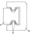
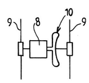
- the head 8 is slidably mounted and guided by two fixed guide rails 9.
- the two rails 9 are located on either side of the head 8 (on either side in a direction perpendicular to the longitudinal direction A).
- the head 8 is guided in translation by the rails 9 and receives the pulling and pushing forces via one end of the mechanism 21, for example a connecting rod 213 is connected to the head 8 at the level of a connection 11 ball joint or pivot.
- the mechanical system converting the rotational movement of the rotating shaft 211 into a translational movement of the head 8 can be connected to a central zone of the head 8 via a link 11 located on a longitudinal straight line A passing through the axis of translation of the rod 50.
- this straight line may also intersect the straight line passing through the rotating shaft 211 of the motor 210.
- each end of the head 8 can be slidably mounted on a rail 9.
- the head 8 can be slidably mounted on the guide rail 9 via a set 12 of rollers and/or balls.
- the sliding system can also be of the precision rail type or any other suitable guide system (preferably not using oil in the case where the axis of the rod is vertical in the position of use).
- carriages (with rollers or ball bearings) are screwed onto the head 8 and move with it.
- the rails 9 are for example fixed to the frame of the device.
- a passive (or active) cartridge can nevertheless be mounted on each of the carriages.
- the head 8 comprises an elastic portion 10 which is configured to generate on the rail(s) 9 a force transverse to the longitudinal direction A.
- the elastic portion 10 generates a permanent transverse force (a force) on the rail(s) 9.
- the aforementioned arrangement makes it possible to at least partially rebalance these transverse forces in the device 1.
- the force Fm exerted by the motion transformation mechanism 21 induces a tensile component Ft on the rod 50 and a transverse thrust component F1 towards one of the rails 9.
- the elastic portion 10 is configured to generate on this same rail 9 a continuous force F2 in the direction opposite to this thrust F1 and which at least partially compensates for it (for example the force F2 is sized to halve the thrust force F1).
- a force F2 can also be generated on the other rail 9; this has no particular influence on the proper functioning of the device.
- this force F2 generated by the elastic portion is preferably constant, whereas the thrust F1 has an intensity which varies cyclically during the movements.
- the value of F2 can be chosen to partially compensate for the maximum intensity of F1 during the cycle.
- the maximum thrust force (when operating at low load, the spring force will be greater than the thrust force.
- the elastic portion 10 permanently performs a "transverse compensating load".
- the final effort resulting in the mechanism is thus limited and makes it possible to limit the stresses in the operating phase generating the most effort. A better balancing or clipping of the transverse forces is obtained.
- this solution provides a second guide rail which, together with the elastic member 10, reduces the lateral forces .
- the elastic portion 10 can be located between the central zone of the head 8 and one of the two rails 9.
- This elastic portion 10 can comprise a spring or a prestressed deformable zone or any other member generating a force. appropriate.
- this elastic portion may comprise a spring formed by a loop-shaped portion (for example with two lobes) of a part of the body of the head 8.
- the elastic portion 10 can be integrated into (or constituted by) the head 8.
- the elements 8 and 10 can be separate parts or the same part.
- the compressive force of the fluid is obtained by a traction (rise) of the rod 50.
- the compressive force of the fluid can be obtained by a push (descent) of the rod 50.
- the lateral forces are reversed with respect to the description above.
- the force F2 of the elastic portion 10 can also simply be reversed (either by moving this elastic portion to the other side of the head or by modifying the structure of the elastic portion 10 so that its force is directed to oppose too great an effort on the side concerned).
- the piston 5 comprises a tubular portion mounted around a fixed central guide 15 .
- a terminal end of the central guide 15 forming the fixed wall delimiting a part of the compression chamber 3 with the tubular portion of the piston 5.
- the apparatus 1 is of the type with one compression stage (fluid compressed only once).
- the invention also applies in the same way to a compression device with two compression stages (fluid undergoing two compressions in series).
- the apparatus 1 may comprise a tubular piston 5 cooperating with a tubular cavity 14 or fixed chamber which is closed at its lower end to delimit two chambers 3, 4 of compression.
- the intake system 2 communicates with a first compression chamber 3.
- the architecture comprises a transfer system 6 (valve or other) communicating with the first 3 and the second 4 compression chamber and configured to allow the transfer of compressed fluid in the first 3 compression chamber to the second 4 compression chamber.
- the mobile piston 5 alternately compressing the fluid in the first 3 (towards the second chamber 4) and in the second 4 compression chamber according to its direction of movement.
- the evacuation system 7 communicates with the second chamber 4 of compression.
- the device 1 can have the following operating characteristics: piston stroke of between 40 and 160 mm, a motor rotation speed of the order of 80 rpm to 500 rpm (corresponding to a frequency of between 1.3 Hz and 8.5 Hz for the piston 5).
- the thrust force F1 can be of the order of 10-20% of Ft while the opposite force generated by the elastic member 10 can be of the order of 5-10% from Ft.
- the architecture eliminates the need for an oil bath lubrication system that would ooze on the cryogenic part.
- the architecture avoids having to manage an oil bath during maintenance operations. Only any lubricators which provide passive self-lubrication in operation of certain elements of the mechanism must be recharged.).
- the solution is compact and lightweight and can be applied to any type of piston pump and any type of crank drive mechanism(s).
Landscapes
- Engineering & Computer Science (AREA)
- Mechanical Engineering (AREA)
- General Engineering & Computer Science (AREA)
- Compressor (AREA)
- Compressors, Vaccum Pumps And Other Relevant Systems (AREA)
- Filling Or Discharging Of Gas Storage Vessels (AREA)
- Separation By Low-Temperature Treatments (AREA)
- Reciprocating Pumps (AREA)
Priority Applications (6)
| Application Number | Priority Date | Filing Date | Title |
|---|---|---|---|
| CA3217932A CA3217932A1 (fr) | 2021-05-21 | 2022-05-04 | Appareil de compression et station de remplissage comprenant un tel appareil |
| CN202280029447.4A CN117242260A (zh) | 2021-05-21 | 2022-05-04 | 压缩设备以及包括这种设备的充装站 |
| US18/562,822 US20240230032A1 (en) | 2021-05-21 | 2022-05-04 | Compression apparatus and filling station comprising such an apparatus |
| KR1020237040021A KR20240013111A (ko) | 2021-05-21 | 2022-05-04 | 압축 장치, 및 그러한 장치를 포함하는 충전 스테이션 |
| JP2023564083A JP2024517636A (ja) | 2021-05-21 | 2022-05-04 | 圧縮装置及びそのような装置を含む充填ステーション |
| EP22727821.5A EP4341560B1 (fr) | 2021-05-21 | 2022-05-04 | Appareil de compression et station de remplissage comprenant un tel appareil |
Applications Claiming Priority (2)
| Application Number | Priority Date | Filing Date | Title |
|---|---|---|---|
| FR2105323A FR3123094B1 (fr) | 2021-05-21 | 2021-05-21 | Appareil de compression et station de remplissage comprenant un tel appareil. |
| FRFR2105323 | 2021-05-21 |
Publications (1)
| Publication Number | Publication Date |
|---|---|
| WO2022243040A1 true WO2022243040A1 (fr) | 2022-11-24 |
Family
ID=77226877
Family Applications (1)
| Application Number | Title | Priority Date | Filing Date |
|---|---|---|---|
| PCT/EP2022/061961 Ceased WO2022243040A1 (fr) | 2021-05-21 | 2022-05-04 | Appareil de compression et station de remplissage comprenant un tel appareil |
Country Status (8)
| Country | Link |
|---|---|
| US (1) | US20240230032A1 (https=) |
| EP (1) | EP4341560B1 (https=) |
| JP (1) | JP2024517636A (https=) |
| KR (1) | KR20240013111A (https=) |
| CN (1) | CN117242260A (https=) |
| CA (1) | CA3217932A1 (https=) |
| FR (1) | FR3123094B1 (https=) |
| WO (1) | WO2022243040A1 (https=) |
Families Citing this family (1)
| Publication number | Priority date | Publication date | Assignee | Title |
|---|---|---|---|---|
| FR3151359B1 (fr) * | 2023-07-18 | 2026-03-27 | Air Liquide | Appareil de compression de fluide et station de remplissage |
Citations (6)
| Publication number | Priority date | Publication date | Assignee | Title |
|---|---|---|---|---|
| US1812954A (en) * | 1929-01-05 | 1931-07-07 | Heylandt Christian Wilhel Paul | Method and device for producing compressed gas from liquefied gas |
| FR783104A (fr) * | 1934-05-01 | 1935-07-08 | Pompe à liquide à basse température | |
| US3251602A (en) * | 1959-06-29 | 1966-05-17 | Chemetron Corp | Apparatus for handling liquefied gases |
| DE10222313C1 (de) * | 2002-05-18 | 2003-11-27 | Man B & W Diesel As Kopenhagen | Kreuzkopfmotor |
| US20070028628A1 (en) * | 2005-08-03 | 2007-02-08 | David Jonathan Chalk | Multi-speed compressor/pump apparatus |
| EP2169242A1 (en) * | 2008-09-29 | 2010-03-31 | Nuovo Pignone S.P.A. | Crank mechanism for a reciprocating compressor |
Family Cites Families (10)
| Publication number | Priority date | Publication date | Assignee | Title |
|---|---|---|---|---|
| AT342178B (de) * | 1973-04-30 | 1978-03-28 | Braun Anton | Kolbenmaschine |
| JPH0253635B2 (https=) * | 1979-11-28 | 1990-11-19 | Braun Anton | |
| JPH08144963A (ja) * | 1994-11-25 | 1996-06-04 | Nabco Ltd | 液化ガス用ポンプ装置 |
| JP5107390B2 (ja) * | 2005-01-07 | 2012-12-26 | 三菱重工業株式会社 | 低温流体用昇圧装置 |
| JP5374022B2 (ja) * | 2007-02-13 | 2013-12-25 | 三菱重工業株式会社 | 水素供給ステーション |
| DE102007047419A1 (de) * | 2007-10-04 | 2009-04-09 | Robert Bosch Gmbh | Kolbenpumpe zur Förderung eines Fluids und zugehöriges Bremssystem |
| WO2010126959A2 (en) * | 2009-04-30 | 2010-11-04 | Tsc Offshore Group Limited | Biaxial alignment assembly for force delivery device |
| JP6700956B2 (ja) * | 2016-05-10 | 2020-05-27 | 株式会社スギノマシン | 往復動ポンプ |
| US11434902B2 (en) * | 2019-03-11 | 2022-09-06 | Ingersoll-Rand Industrial U.S., Inc. | Electric diaphragm pump with offset slider crank |
| JP6781795B2 (ja) * | 2019-04-09 | 2020-11-04 | 株式会社Ihi回転機械エンジニアリング | 往復動圧縮機 |
-
2021
- 2021-05-21 FR FR2105323A patent/FR3123094B1/fr active Active
-
2022
- 2022-05-04 US US18/562,822 patent/US20240230032A1/en active Pending
- 2022-05-04 JP JP2023564083A patent/JP2024517636A/ja active Pending
- 2022-05-04 CN CN202280029447.4A patent/CN117242260A/zh active Pending
- 2022-05-04 EP EP22727821.5A patent/EP4341560B1/fr active Active
- 2022-05-04 KR KR1020237040021A patent/KR20240013111A/ko active Pending
- 2022-05-04 CA CA3217932A patent/CA3217932A1/fr active Pending
- 2022-05-04 WO PCT/EP2022/061961 patent/WO2022243040A1/fr not_active Ceased
Patent Citations (6)
| Publication number | Priority date | Publication date | Assignee | Title |
|---|---|---|---|---|
| US1812954A (en) * | 1929-01-05 | 1931-07-07 | Heylandt Christian Wilhel Paul | Method and device for producing compressed gas from liquefied gas |
| FR783104A (fr) * | 1934-05-01 | 1935-07-08 | Pompe à liquide à basse température | |
| US3251602A (en) * | 1959-06-29 | 1966-05-17 | Chemetron Corp | Apparatus for handling liquefied gases |
| DE10222313C1 (de) * | 2002-05-18 | 2003-11-27 | Man B & W Diesel As Kopenhagen | Kreuzkopfmotor |
| US20070028628A1 (en) * | 2005-08-03 | 2007-02-08 | David Jonathan Chalk | Multi-speed compressor/pump apparatus |
| EP2169242A1 (en) * | 2008-09-29 | 2010-03-31 | Nuovo Pignone S.P.A. | Crank mechanism for a reciprocating compressor |
Also Published As
| Publication number | Publication date |
|---|---|
| CA3217932A1 (fr) | 2022-11-24 |
| EP4341560A1 (fr) | 2024-03-27 |
| CN117242260A (zh) | 2023-12-15 |
| EP4341560B1 (fr) | 2025-11-19 |
| JP2024517636A (ja) | 2024-04-23 |
| KR20240013111A (ko) | 2024-01-30 |
| FR3123094B1 (fr) | 2023-12-08 |
| FR3123094A1 (fr) | 2022-11-25 |
| US20240230032A1 (en) | 2024-07-11 |
Similar Documents
| Publication | Publication Date | Title |
|---|---|---|
| CN100439705C (zh) | 压缩装置 | |
| EP4107397B1 (fr) | Appareil de compression et station de remplissage comprenant un tel appareil | |
| FR3107572A1 (fr) | Appareil de compression et station de remplissage comprenant un tel appareil | |
| EP4341560B1 (fr) | Appareil de compression et station de remplissage comprenant un tel appareil | |
| WO1988006250A1 (fr) | Piston pour moteurs a combustion interne et machines analogues | |
| FR3036548A1 (fr) | Actionneur electromecanique | |
| FR2739428A1 (fr) | Verin de puissance a frottements secs reduits | |
| FR2745073A1 (fr) | Compresseur refrigerant a capacite variable | |
| WO2022263086A1 (fr) | Installation de pompage de fluide cryogénique et station de remplissage comprenant une telle installation | |
| WO2022263085A1 (fr) | Installation de pompage de fluide cryogénique et station de remplissage comprenant une telle installation | |
| FR2718493A1 (fr) | Rondelle de butée pour compresseur rotatif. | |
| FR2653826A1 (fr) | Moteur a rapport volumetrique variable. | |
| JP2024517636A5 (https=) | ||
| EP4355999B1 (fr) | Installation de pompage de fluide cryogénique et station de remplissage comprenant une telle installation | |
| US20250026627A1 (en) | Fluid compression apparatus and filling station | |
| FR3132742A3 (fr) | Piston de pompe et pompe cryogénique comprenant un tel piston | |
| CN116696950B (zh) | 一种高密性轴承压盖 | |
| CN219497624U (zh) | 高压断路器操动机构的储能模块及高压断路器 | |
| WO2018158527A1 (fr) | Dispositif presseur pour exercer un effort de maintien sur un dispositif de transmission et moteur muni d'un tel dispositif | |
| FR3067386A1 (fr) | Machine de detente | |
| FR2730006A1 (fr) | Embiellage rigide notamment pour moteur | |
| BE870198A (fr) | Elements en volute complementaires, notamment pour pompes a liquides | |
| FR3140655A3 (fr) | Appareil et procédé de compression de fluide cryogénique | |
| FR3102813A1 (fr) | Bielle de longueur variable avec entrée d’huile latérale | |
| JP2001056094A (ja) | 潤滑油供給装置の貯油方法 |
Legal Events
| Date | Code | Title | Description |
|---|---|---|---|
| 121 | Ep: the epo has been informed by wipo that ep was designated in this application |
Ref document number: 22727821 Country of ref document: EP Kind code of ref document: A1 |
|
| WWE | Wipo information: entry into national phase |
Ref document number: 202280029447.4 Country of ref document: CN Ref document number: 2023564083 Country of ref document: JP |
|
| WWE | Wipo information: entry into national phase |
Ref document number: 3217932 Country of ref document: CA |
|
| WWE | Wipo information: entry into national phase |
Ref document number: 18562822 Country of ref document: US |
|
| WWE | Wipo information: entry into national phase |
Ref document number: 2022727821 Country of ref document: EP |
|
| NENP | Non-entry into the national phase |
Ref country code: DE |
|
| ENP | Entry into the national phase |
Ref document number: 2022727821 Country of ref document: EP Effective date: 20231221 |
|
| WWG | Wipo information: grant in national office |
Ref document number: 2022727821 Country of ref document: EP |