WO2022239643A1 - ブレ補正装置、レンズ鏡筒、及び撮像装置 - Google Patents
ブレ補正装置、レンズ鏡筒、及び撮像装置 Download PDFInfo
- Publication number
- WO2022239643A1 WO2022239643A1 PCT/JP2022/018911 JP2022018911W WO2022239643A1 WO 2022239643 A1 WO2022239643 A1 WO 2022239643A1 JP 2022018911 W JP2022018911 W JP 2022018911W WO 2022239643 A1 WO2022239643 A1 WO 2022239643A1
- Authority
- WO
- WIPO (PCT)
- Prior art keywords
- blur correction
- lock ring
- correction device
- holding frame
- lock member
- Prior art date
- Legal status (The legal status is an assumption and is not a legal conclusion. Google has not performed a legal analysis and makes no representation as to the accuracy of the status listed.)
- Ceased
Links
Images



Classifications
-
- G—PHYSICS
- G03—PHOTOGRAPHY; CINEMATOGRAPHY; ANALOGOUS TECHNIQUES USING WAVES OTHER THAN OPTICAL WAVES; ELECTROGRAPHY; HOLOGRAPHY
- G03B—APPARATUS OR ARRANGEMENTS FOR TAKING PHOTOGRAPHS OR FOR PROJECTING OR VIEWING THEM; APPARATUS OR ARRANGEMENTS EMPLOYING ANALOGOUS TECHNIQUES USING WAVES OTHER THAN OPTICAL WAVES; ACCESSORIES THEREFOR
- G03B5/00—Adjustment of optical system relative to image or object surface other than for focusing
-
- G—PHYSICS
- G03—PHOTOGRAPHY; CINEMATOGRAPHY; ANALOGOUS TECHNIQUES USING WAVES OTHER THAN OPTICAL WAVES; ELECTROGRAPHY; HOLOGRAPHY
- G03B—APPARATUS OR ARRANGEMENTS FOR TAKING PHOTOGRAPHS OR FOR PROJECTING OR VIEWING THEM; APPARATUS OR ARRANGEMENTS EMPLOYING ANALOGOUS TECHNIQUES USING WAVES OTHER THAN OPTICAL WAVES; ACCESSORIES THEREFOR
- G03B17/00—Details of cameras or camera bodies; Accessories therefor
- G03B17/02—Bodies
- G03B17/12—Bodies with means for supporting objectives, supplementary lenses, filters, masks, or turrets
-
- G—PHYSICS
- G03—PHOTOGRAPHY; CINEMATOGRAPHY; ANALOGOUS TECHNIQUES USING WAVES OTHER THAN OPTICAL WAVES; ELECTROGRAPHY; HOLOGRAPHY
- G03B—APPARATUS OR ARRANGEMENTS FOR TAKING PHOTOGRAPHS OR FOR PROJECTING OR VIEWING THEM; APPARATUS OR ARRANGEMENTS EMPLOYING ANALOGOUS TECHNIQUES USING WAVES OTHER THAN OPTICAL WAVES; ACCESSORIES THEREFOR
- G03B2205/00—Adjustment of optical system relative to image or object surface other than for focusing
- G03B2205/0007—Movement of one or more optical elements for control of motion blur
Definitions
- the blur correction device includes a lens holding frame that holds a lens, a holding frame that movably holds the lens holding frame, and the lens holding frame with respect to the holding frame as an optical axis.
- a first drive unit that drives in a crossing direction; a lock member that moves between a lock position that restricts movement of the lens holding frame; and a release position that releases the restriction; and a detection unit for detecting.
- the lens barrel includes the blur correction device.
- an imaging device includes the blur correction device.
- FIG. 1 is a diagram showing a camera including a lens barrel including a blur correction device according to one embodiment, and a camera body.
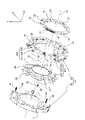
- FIG. 2 is an exploded perspective view of the blur correction device.
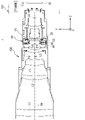
- FIG. 3 is a cross-sectional view of the blur correction device.
- FIGS. 4A and 4B are diagrams of the blur correction device as seen from the camera body side.
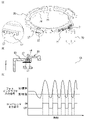
- FIG. 5(A) is a perspective view of the lock ring
- FIG. 5(B) is a cross-sectional view showing the relationship between the lock ring and the fixing frame
- FIG. FIG. 4 is a diagram showing changes in signal level output from a photointerrupter;
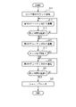
- FIG. 6 is a flow chart showing the process of controlling the motor.
- FIG. 7 is a timing chart for explaining the processing of FIG.
- the blur correction device 80 according to one embodiment will be described in detail with reference to the drawings.
- the +Z direction is the direction from the object toward the camera body 101 at the camera position (hereinafter referred to as normal position) when the photographer takes a landscape image with the optical axis OA horizontal.
- the direction toward the right side when viewed from the camera body 101 side at the normal position is defined as the +X direction.
- the upward direction in the normal position is the +Y direction.
- FIG. 1 is a diagram showing a camera 1 including a lens barrel 100 including a blur correction device 80 according to this embodiment and a camera body 101.
- the lens barrel 100 is detachable from the camera body 101, but the lens barrel 100 and the camera body 101 may be integrated.
- the camera body 101 includes an image sensor IS, a control unit 112, and the like inside.
- the imaging element IS is composed of a photoelectric conversion element such as a CCD (Charge Coupled Device), for example, and converts the subject image formed by the imaging optical system (lens barrel 100 attached to the camera body 101) into an electrical signal. do.
- CCD Charge Coupled Device
- the control unit 112 includes a CPU (Central Processing Unit) and the like, and controls the overall operation of the camera 1 related to shooting, including focus driving in the camera body 101 and the attached lens barrel 100, and blur correction of captured images due to camera shake and the like. Overall control of operations.
- CPU Central Processing Unit
- the lens barrel 100 includes a fixed barrel 10. As shown in FIG. 1, the fixed cylinder 10 is composed of a plurality of parts in this embodiment, it may be composed of a single part. As shown in FIG. 1, the fixed barrel 10 is fixed with a lens mount LM that allows the lens barrel 100 to be detachable from the camera body 101 .
- the lens barrel 100 includes a plurality of lens groups L1 to L9 sequentially arranged along the common optical axis OA.
- the lens group L4 is held by a lens holding frame F4
- the lens group L6 is held by a lens holding frame F6
- the lens group L8 is held by a lens holding frame F8.
- Other lens groups are held by a fixed barrel 10 .
- Each of the lens groups L1 to L9 may be composed of one lens, or may be composed of a plurality of lenses.
- the lens group L6 is a vibration reduction (VR) lens, and can be moved in a plane perpendicular to the optical axis OA by a vibration reduction device 80, which will be described later, when performing vibration reduction.
- VR vibration reduction
- FIG. 2 is an exploded perspective view of the blur correction device 80.
- the blur correction device 80 includes a movable frame 60, a holding frame 30, and a lock ring 20.
- the movable frame 60 holds the lens group L6 via the lens holding frame F6 and moves within the XY plane perpendicular to the optical axis OA (Z axis).
- the holding frame 30 includes a base member 40 and a fixed frame 50.
- the base member 40 is a substantially annular member having a circular hole 41 in the center.
- a frame 60 is held so as to be relatively movable within a plane perpendicular to the optical axis OA. More specifically, the base member 40 holds the movable frame 60 via steel balls 43 and coil springs 42 .
- the movable frame 60 and the base member 40 are urged by the coil spring 42 in a direction to press against each other with the steel ball 43 interposed therebetween.
- the coil spring 42 connects the base member 40 and the movable frame 60 in the optical axis OA direction and prevents the base member 40 and the movable frame 60 from separating in the optical axis OA direction.
- the base member 40 and the movable frame 60 each have contact surfaces that contact the steel balls 43 at positions where the steel balls 43 are arranged.
- the steel ball 43 rotates between the contact surface of the base member 40 and the contact surface of the movable frame 60 . Thereby, the movable frame 60 can move in parallel with respect to the base member 40 in a low-friction state.
- the fixed frame 50 is a substantially annular member having a circular hole 51 in the center. Unlike the movable frame 60, the fixed frame 50 does not move within a plane perpendicular to the optical axis OA.
- FIG. 3 is a cross-sectional view of the blur correction device 80.
- a lens group L6 held by a movable frame 60 is moved within the XY plane by VCMs (voice coil motors) 90X and 90Y to correct image blurring.
- the VCM 90X is an actuator for driving the lens group L6 in the X-axis direction, and includes an X-axis direction driving coil 61X, a pair of X-axis direction driving magnets 52X, and a yoke 53X.
- the VCM 90Y is an actuator for driving the lens group L6 in the Y-axis direction, and includes a Y-axis direction driving coil 61Y, a pair of Y-axis direction driving magnets 52Y, and a yoke 53Y.
- the pair of magnets 52X for driving in the X-axis direction and the pair of magnets 52Y for driving in the Y-axis direction are in-plane dipole-polarized magnets having two poles polarized into N and S poles.
- the X-axis direction driving coil 61X and the Y-axis direction driving coil 61Y that drives in the Y-axis direction are attached to the movable frame 60.
- a yoke 53X is attached to the fixed frame 50 at a position corresponding to the X-axis direction driving coil 61X, and an X-axis direction driving magnet 52X is attached to the yoke 53X.
- a yoke 53Y is attached to a position corresponding to the Y-axis direction driving coil 61Y of the movable frame 60, and a Y-axis direction driving magnet 52Y is attached to the yoke 53Y.
- the Y-axis direction driving coil 61Y receives the Lorentz force and moves the movable frame. 60 is driven in the Y-axis direction. Thereby, the lens group L6 held by the movable frame 60 can be moved in the Y-axis direction.
- the yoke 53Y and the Y-axis direction driving magnet 52Y may be attached to the movable frame 60, and the Y-axis direction driving coil 61Y may be attached to the fixed frame 50.
- FIG. The same applies to the VCM 90X, so detailed description will be omitted.
- the lock ring 20 is a substantially annular member having a circular hole 21 in the center, and is a member for locking the movable frame 60 so that it does not move relative to the holding frame 30 when shake correction is not performed. is.
- FIGS. 4A and 4B are diagrams of the blur correction device 80 viewed from the camera body 101 side.
- FIG. 4A shows a case where the lock ring 20 is in an unlocked position allowing movement of the lens unit L6 within a plane perpendicular to the optical axis OA
- FIG. is in the lock position that restricts the movement of the lens group L6 within the plane perpendicular to the optical axis OA.
- the lower left figure is an enlarged view of the dotted line portion.
- the lock ring 20 is rotated around the optical axis OA by a motor 70 (see FIG. 2) attached to the fixed frame 50, and has a lock position that restricts the movement of the movable frame 60, an unlock position that releases the restriction, move between
- a gear portion 22 is formed on the outer peripheral portion of the lock ring 20, and is attached to the rotation shaft of the motor 70. It meshes with the pinion gear 71 which is attached.
- the rotational force of the motor 70 is transmitted to the lock ring 20, and the forward and reverse rotation of the motor 70 drives the lock ring 20 to the locked position (FIG. 4(B)) and the unlocked position (FIG. 4(A)).
- a DC motor, a stepping motor, an ultrasonic motor, or the like can be used as the motor 70 .
- protrusions 23 protruding toward the optical axis OA and gaps 24 are alternately formed in the circumferential direction.
- the protrusion 23 contacts the protrusion 66 of the movable frame 60 and prohibits the movable frame 60 from moving.
- the lock ring 20 is rotated from the locked position to the unlocked position around the optical axis OA, the contact state between the projection 23 and the projection 66 of the movable frame 60 is released, and at the unlocked position, the projection 66 , face the gaps 24 formed between the protrusions 23 . Thereby, the movable frame 60 can move for the blur correction operation.
- a restricting member 58 for restricting the movement of the lock ring 20 is attached to the fixed frame 50 so that the lock ring 20 does not move from the lock position due to impact or vibration.
- the restricting member 58 is, for example, a leaf spring.
- a concave portion 29 is provided on the outer peripheral surface of the lock ring 20 with which the tip of the regulating member 58 contacts.
- the recess 29 is provided at a position where it does not engage with the tip of the regulating member 58 when the lock ring 20 is at the unlock position, and engages with the tip of the regulating member 58 when the lock ring 20 is at the lock position. It is Therefore, when the lock ring 20 is in the locked position, the tip of the regulating member 58 engages with the concave portion 29 and biases the lock ring 20 in the direction opposite to the direction in which the lock ring 20 moves from the locked position to the unlocked position. . Thereby, the lock ring 20 can be reliably fixed at the locked position.
- the first contact portion 25 contacts one end of the elastic member 54 attached to the fixed frame 50 to stop the lock ring 20, and the lock ring 20 is driven to the lock position. and a second contact portion 26 that contacts the other end of the elastic member 54 to stop the lock ring 20 .
- the elastic member 54 is made of rubber, for example.
- the moving speed (rotational speed) of the lock ring 20 remains high when the first contact portion 25 or the second contact portion 26 contacts the elastic member 54, the first contact portion 25 or the second contact portion The impact when 26 comes into contact with elastic member 54 increases, and there is a possibility that a loud sound will be generated. Therefore, when the first contact portion 25 or the second contact portion 26 and the elastic member 54 come into contact with each other, it is desirable that the movement speed of the lock ring 20 is low.
- the motor 70 may stop driving before the first contact portion 25 or the second contact portion 26 contacts the elastic member 54, and the lock ring 20 may not reach the lock position/unlock position.
- a detection unit that detects the amount of movement (amount of rotation) of the lock ring 20 is provided, and the motor 70 is controlled based on the amount of movement of the lock ring 20 detected by the detection unit. controls the movement speed (rotational speed) of the
- FIG. 5(A) is a perspective view of the lock ring 20
- FIG. 5(B) is a cross-sectional view showing the relationship between the lock ring 20 and the fixing frame 50.
- the lower left figure is an enlarged view of the dotted line portion.
- a comb tooth portion 27 for detecting the amount of movement of the lock ring 20 is provided on the outer peripheral portion of the lock ring 20 .
- the comb tooth portion 27 is arranged in a groove 59 formed in the fixed frame 50 .
- a photointerrupter 57 is provided in the groove 59 of the fixed frame 50 .
- the photointerrupter 57 has a light-emitting portion 57a and a light-receiving portion 57b facing the light-emitting portion 57a with the comb tooth portion 27 interposed therebetween and receiving the light emitted from the light-emitting portion 57a.
- the light-emitting portion 57a and the light-receiving portion 57b may be arranged reversely.
- FIG. 5(C) is a diagram showing changes in the signal level output from the photointerrupter 57 as the lock ring 20 moves.
- the comb tooth portion 27 blocks light passing between the light emitting portion 57a and the light receiving portion 57b, so that the output signal level of the photointerrupter 57 changes. do.
- the output signal of the photointerrupter 57 is an analog signal, it is converted into a digital signal by, for example, a comparator.
- the comparator outputs an ON signal when the output signal level of the photointerrupter 57 is equal to or higher than a first threshold, and outputs an OFF signal when equal to or lower than a second threshold smaller than the first threshold.
- the amount of movement of the lock ring 20 can be detected based on the number of edges of the digital signal output from the comparator.
- FIG. 6 is a flow chart showing the process of controlling the motor 70.
- FIG. 7 is a timing chart for explaining the processing of FIG. In FIG. 7, the number written above the comparator output signal is the number of edges.
- FIG. 6 The process of FIG. 6 is started when a command is issued to move the lock ring 20 from the locked position to the unlocked position or from the unlocked position to the locked position.
- a command is issued to move the lock ring 20 from the locked position to the unlocked position or from the unlocked position to the locked position.
- the lock ring 20 is rotated clockwise (normally) from the locked position to the unlocked position.
- step S11 the control unit 112 starts counting the number of edges of the output signal of the comparator. For example, in FIG. 7, at time t1, control unit 112 receives a command to move lock ring 20 to the unlocked position. In this case, the controller starts counting the number of edges of the comparator output signal from time t1.
- step S12 the control unit 112 starts energizing the motor 70 at the first duty ratio D1.
- the motor 70 is energized at the first duty ratio D1 from time t1.
- the lock ring 20 moves (rotates) at, for example, the first speed.
- a short brake is to temporarily stop the motor 70 by short-circuiting the terminals of the motor 70 .
- step S13 the control unit 112 determines whether or not a predetermined time Ta has elapsed since the motor 70 started to be energized at the first duty ratio D1.
- the predetermined time Ta is, for example, 3 [ms]
- the pinion gear 71 attached to the rotating shaft of the motor 70 idles for the amount of backlash, and is sufficient to mesh with the gear portion 22 of the lock ring 20 .
- Time is set.
- the first duty ratio D1 is set to a value that can reduce collision noise when the pinion gear 71 contacts the gear portion 22 .
- step S13/NO the control unit 112 continues energization at the first duty ratio D1.
- step S13/YES the process proceeds to step S15, and the control unit 112 energizes the motor 70 at a second duty ratio D2 that is greater than the first duty ratio D1.
- the control unit 112 changes the duty ratio of the energization of the motor 70 from the first duty ratio D1 to the second duty ratio D2 (D1 ⁇ D2).
- the rotation speed of the motor 70 increases, so that the movement speed of the lock ring 20 increases from the first speed to the second speed.
- the control unit 112 increases the moving speed of the lock ring 20, so that the lock ring 20 reaches the locked position or the unlocked position. time can be shortened.
- step S17 the control unit 112 determines whether the number of edges for which counting was started in step S11 is less than a threshold (for example, 7 edges). In step S17, it is determined whether or not the lock ring 20 has moved by a predetermined amount (predetermined angle).
- the threshold value of the number of edges is set within a moving amount range in which the lock ring 20 does not come into contact with the elastic member 54 .
- step S17/YES If the number of edges is less than the threshold (step S17/YES), the control unit 112 continues to energize the motor 70 at the second duty ratio D2. On the other hand, if the number of edges is equal to or greater than the threshold (step S17/NO), the process proceeds to step S19, and the control section 112 energizes the motor 70 with a third duty ratio D3 that is smaller than the second duty ratio D2. For example, when the edge count threshold is 7, as shown in FIG. D2 is changed to a third duty ratio D3 (D3 ⁇ D2). As a result, as shown in FIG. 7, the rotation speed of the motor 70 is reduced, so that the moving speed of the lock ring 20 is also reduced from the second speed to the third speed. Since the movement speed of the lock ring 20 can be reduced before the lock ring 20 contacts the elastic member 54, the impact force when the lock ring 20 collides with the elastic member 54 is reduced and the collision noise is reduced. can be made
- step S21 the control unit 112 determines whether or not a predetermined time Tc (for example, 10 [ms]) has elapsed since energization with the third duty ratio D3 was started.
- a predetermined time Tc for example, 10 [ms]
- the lock ring 20 contacts the elastic member 54 attached to the fixed frame 50 when the motor 70 is energized at the third duty ratio D3 for the predetermined time Tc. It is set at a time that can guarantee that
- step S21/NO If the predetermined time Tc has not elapsed (step S21/NO), the control unit 112 continues energization at the third duty ratio D3. On the other hand, if the predetermined time Tc has passed (step S21/YES), the process proceeds to step S23, the control unit 112 brings the motor 70 into the short brake state, and terminates the process. That is, the controller 112 stops driving the motor 70 after the lock ring 20 contacts the elastic member 54 . In the example shown in FIG. 7, the control unit 112 puts the motor 70 into the short brake state at time t4 when the predetermined time Tc has elapsed from time t3, and ends the process. Thereby, the lock ring 20 can be reliably moved to the locked position.
- first duty ratio D1 may be the same as the third duty ratio D3 as long as it is smaller than the second duty ratio D2, or may be larger or smaller than the third duty ratio D3. good.
- the blur correction device 80 includes the movable frame 60 that holds the lens group L6, the holding frame 30 that movably holds the movable frame 60, and the holding frame 30 , VCMs 90X and 90Y that drive the movable frame 60 in a direction intersecting the optical axis OA, a lock position that restricts movement of the movable frame 60, and an unlock position that releases the restriction.
- a ring 20 and a detector that detects the amount of movement of the lock ring 20 are provided.
- the detection section is realized by the comb tooth section 27 formed in a part of the lock ring 20 , the photo interrupter 57 including the light emitting section 57 a and the light receiving section 57 b, and the control section 112 . Since the accurate amount of movement of the lock ring 20 can be grasped, drive control of the motor 70 can be performed based on the amount of movement of the lock ring 20 . As a result, for example, before the lock ring 20 contacts the elastic member 54, the rotational speed of the motor 70 is reduced to reduce the collision noise between the lock ring 20 and the elastic member 54, or to move the lock ring 20 to the locked position. / It becomes possible to reliably move to the unlock position.
- the motor 70 is a stepping motor, it is possible to detect stepping out of the stepping motor. Further, more precise control can be achieved compared to the case where the motor 70 is controlled based on the elapsed time from when the lock ring 20 is started to be driven.
- the blur correction device 80 includes a motor 70 that drives the lock ring 20 and a control section 112 that controls the motor 70 based on the detected amount of movement of the lock ring 20 .
- a motor 70 that drives the lock ring 20
- a control section 112 that controls the motor 70 based on the detected amount of movement of the lock ring 20 .
- the lock ring 20 has a first contact portion 25 that contacts the holding frame 30 at the locked position and a second contact portion 26 that contacts the holding frame 30 at the unlocked position.
- the unit 112 reduces the moving speed of the lock ring 20 before the holding frame 30 contacts the first contact portion 25 or the second contact portion 26 based on the detected amount of movement of the lock ring 20 . Thereby, the collision noise between the lock ring 20 and the elastic member 54 can be reduced.
- control unit 112 drives the motor 70 after the holding frame 30 and the first contact portion 25 or the second contact portion 26 come into contact with each other based on the detected amount of movement of the lock ring 20 . Stop. As a result, the lock ring 20 can be reliably stopped at the locked position or the unlocked position, thereby improving the reliability of movement control of the lock ring 20 .
- the control unit 112 moves the lock ring 20 at the first speed until the predetermined time Ta elapses, and after the predetermined time Ta elapses, the lock ring 20 moves at a speed higher than the first speed. Move lock ring 20 at a second speed. As a result, collision noise generated due to backlash between the pinion gear 71 attached to the rotating shaft of the motor 70 and the gear portion 22 can be reduced.
- control unit 112 controls the motor 70 based on the number of edges of the digital signal based on the signal indicating the detection state of the light from the light emitting unit 57a in the light receiving unit 57b. Thereby, the amount of movement of the lock ring 20 can be accurately detected.
- the amount of movement of the lock ring 20 is detected without contacting the lock ring 20 .
- the movement of the lock ring 20 is not hindered, so that the motor 70 can be prevented from being overloaded.
- the shake correction device 80 includes a restricting member 58 that restricts movement of the lock ring 20 when the lock ring 20 is in the lock position.
- a restricting member 58 that restricts movement of the lock ring 20 when the lock ring 20 is in the lock position.
- the comb tooth portion 27 formed on a part of the lock ring 20 and the photointerrupter 57 are used to detect the amount of movement of the lock ring 20, but the invention is not limited to this. do not have.
- a scale having a repetitive reflection pattern may be provided on the lock ring 20 and a reflective photosensor may be provided on the fixed frame 50 to detect the amount of movement of the lock ring 20 .
- the fixed frame 50 may be provided with a scale having a reflective pattern, and the lock ring 20 may be provided with a reflective photosensor.
- the lock ring 20 may be provided with the photo interrupter 57 and the fixed frame 50 may be provided with the comb tooth portion 27 .
- the rotation speed of the motor 70 is controlled based on the amount of movement of the lock ring 20.
- the movement speed (rotational speed) of the lock ring 20 is calculated from the amount of movement of the lock ring 20.
- the motor 70 may be controlled based on the moving speed of the lock ring 20 . For example, when the moving speed of the lock ring 20 exceeds a threshold value, the amount of power supplied to the motor 70 is decreased or the duty ratio is decreased so that a collision sound between the lock ring 20 and the elastic member 54 is produced. good too.
- the moving lens type blurring correction device 80 that drives the lens group L6 has been described, but the present invention is not limited to this, and can also be applied to a moving image pickup device type blurring correction device that drives the image pickup device. can be done.
- a holding member that movably holds an imaging element is provided with one of the detecting section and the detected section, and a locking member that can lock the imaging element with respect to the holding member is provided with the other of the detecting section and the detected section. It suffices if the amount of movement of the lock member relative to the member can be detected.
- the lock ring 20 has been described as an example in the above embodiment, the present invention is not limited to this, and can be applied to a configuration in which the lens unit L6 is locked by moving the lock member in the optical axis direction.
- the blur correction device described in the above embodiments can be applied not only to compact digital cameras and single-lens reflex digital cameras, but also to optical devices such as video cameras, binoculars, microscopes, telescopes, and mobile phones.
Landscapes
- Physics & Mathematics (AREA)
- General Physics & Mathematics (AREA)
- Adjustment Of Camera Lenses (AREA)
Abstract
Description
また、上記実施形態ではロックリング20を一例に説明したが、これに限定されず、光軸方向にロック部材を移動させてレンズ群L6をロックする構成にも適用できる。
25 第1接触部
26 第2接触部
27 櫛歯部
30 保持枠
57a 発光部
57b 受光部
58 規制部材
60 可動枠
70 モータ
80 ブレ補正装置
90X,90Y VCM
112 制御部
L6 レンズ群
Claims (11)
- レンズを保持するレンズ保持枠と、
前記レンズ保持枠を移動可能に保持する保持枠と、
前記保持枠に対して前記レンズ保持枠を光軸と交差する方向に駆動する第1駆動部と、
前記レンズ保持枠の移動を規制するロック位置と、前記規制を解除する解除位置と、の間で移動するロック部材と、
前記ロック部材の移動量を検出する検出部と、
を備えるブレ補正装置。 - 前記ロック部材を駆動する第2駆動部と、
前記検出部により検出した前記ロック部材の移動量に基づいて、前記第2駆動部を制御する制御部と、
を備える、請求項1に記載のブレ補正装置。 - 前記ロック部材は、前記解除位置で前記保持枠と接触する第1接触部と、前記ロック位置で前記保持枠と接触する第2接触部と、を有し、
前記制御部は、前記検出部により検出された前記ロック部材の移動量に基づいて、前記保持枠と前記第1接触部または前記第2接触部とが接触する前に、前記ロック部材の移動速度を低下させる、
請求項2に記載のブレ補正装置。 - 前記制御部は、前記検出部により検出した前記ロック部材の移動量に基づいて、前記保持枠と前記第1接触部または前記第2接触部とが接触した後に、前記第2駆動部の駆動を停止する、
請求項3記載のブレ補正装置。 - 前記制御部は、前記ロック部材の移動を開始すると、所定の時間が経過するまでは第1の速度で前記ロック部材を移動させ、前記所定の時間が経過すると、前記第1の速度よりも早い第2の速度で前記ロック部材を移動させる、
請求項2から請求項4のいずれか1項に記載のブレ補正装置。 - 前記検出部は、前記ロック部材の一部に形成された櫛歯部と、発光部と、前記櫛歯部をはさんで前記発光部に対向し、前記発光部から照射された光を受光する受光部と、を含む、
請求項2から請求項5のいずれか1項記載のブレ補正装置。 - 前記制御部は、前記受光部における前記発光部からの光の検出状態を示す信号に基づくデジタル信号のエッジの数に基づいて、前記第2駆動部を制御する、
請求項6に記載のブレ補正装置。 - 前記検出部は、前記ロック部材の移動量を前記ロック部材に非接触で検出する、
請求項1から請求項7のいずれか1項に記載のブレ補正装置。 - 前記ロック部材が前記ロック位置にあるときに、前記ロック部材の移動を規制する規制部材、
を備える請求項1から請求項8のいずれか1項に記載のブレ補正装置。 - 請求項1から請求項9のいずれか1項に記載のブレ補正装置を備えるレンズ鏡筒。
- 請求項1から請求項9のいずれか1項に記載のブレ補正装置を備える撮像装置。
Priority Applications (3)
| Application Number | Priority Date | Filing Date | Title |
|---|---|---|---|
| CN202280033607.2A CN117337410A (zh) | 2021-05-12 | 2022-04-26 | 抖动校正装置、镜头镜筒及拍摄装置 |
| US18/289,909 US12663692B2 (en) | 2021-05-12 | 2022-04-26 | Blur correction device, lens barrel, and imaging apparatus |
| JP2023520959A JP7740331B2 (ja) | 2021-05-12 | 2022-04-26 | ブレ補正装置、レンズ鏡筒、及び撮像装置 |
Applications Claiming Priority (2)
| Application Number | Priority Date | Filing Date | Title |
|---|---|---|---|
| JP2021080713 | 2021-05-12 | ||
| JP2021-080713 | 2021-05-12 |
Publications (1)
| Publication Number | Publication Date |
|---|---|
| WO2022239643A1 true WO2022239643A1 (ja) | 2022-11-17 |
Family
ID=84028276
Family Applications (1)
| Application Number | Title | Priority Date | Filing Date |
|---|---|---|---|
| PCT/JP2022/018911 Ceased WO2022239643A1 (ja) | 2021-05-12 | 2022-04-26 | ブレ補正装置、レンズ鏡筒、及び撮像装置 |
Country Status (4)
| Country | Link |
|---|---|
| US (1) | US12663692B2 (ja) |
| JP (1) | JP7740331B2 (ja) |
| CN (1) | CN117337410A (ja) |
| WO (1) | WO2022239643A1 (ja) |
Citations (3)
| Publication number | Priority date | Publication date | Assignee | Title |
|---|---|---|---|---|
| JP2015197660A (ja) * | 2014-04-03 | 2015-11-09 | キヤノン株式会社 | 光学機器およびその制御方法 |
| JP2017003403A (ja) * | 2015-06-10 | 2017-01-05 | キヤノン株式会社 | エンコーダ信号処理装置およびエンコーダ使用装置 |
| JP2019194691A (ja) * | 2018-04-26 | 2019-11-07 | キヤノン株式会社 | 振れ補正装置、レンズ装置およびカメラシステム |
Family Cites Families (17)
| Publication number | Priority date | Publication date | Assignee | Title |
|---|---|---|---|---|
| US6016221A (en) * | 1992-09-21 | 2000-01-18 | Canon Kabushiki Kaisha | Image-shake preventing device |
| US5973319A (en) * | 1996-04-11 | 1999-10-26 | Canon Kabushiki Kaisha | Position detecting apparatus for use with image blur correcting device having movable member |
| JP3783296B2 (ja) * | 1996-09-26 | 2006-06-07 | ソニー株式会社 | 手振れ補正機能を有した撮像装置 |
| US5974269A (en) * | 1996-11-07 | 1999-10-26 | Canon Kabushiki Kaisha | Image blur preventing apparatus |
| US6208810B1 (en) * | 1997-01-28 | 2001-03-27 | Canon Kabushiki Kaisha | Image blur preventing device |
| US5905917A (en) * | 1997-03-14 | 1999-05-18 | Nikon Corporation | Vibration reduction device |
| JP2001166350A (ja) * | 1999-12-06 | 2001-06-22 | Canon Inc | 防振機能付き装置 |
| JP4539043B2 (ja) * | 2003-08-26 | 2010-09-08 | 株式会社ニコン | ブレ補正装置及びカメラシステム |
| JP4566570B2 (ja) * | 2004-01-30 | 2010-10-20 | キヤノン株式会社 | 光学機器 |
| JP2008191484A (ja) * | 2007-02-06 | 2008-08-21 | Nikon Corp | レンズ鏡筒及びカメラ |
| JP2009169128A (ja) | 2008-01-17 | 2009-07-30 | Canon Inc | レンズ鏡筒及びそれを有する撮像装置 |
| TWI491251B (zh) | 2009-12-30 | 2015-07-01 | Hon Hai Prec Ind Co Ltd | 相機模組 |
| DE102013112357B4 (de) | 2013-11-11 | 2016-05-04 | Zürcher Hochschule für Angewandte Wissenschaften (ZHAW) Zentr. Angewandte Mathematik u. Physik | Optische Einrichtung, Kamera sowie Verfahren zur Verschiebung einer optischen Achse |
| JP6582371B2 (ja) * | 2014-08-18 | 2019-10-02 | リコーイメージング株式会社 | 像振れ補正装置および光学機器 |
| JP6672696B2 (ja) | 2015-10-22 | 2020-03-25 | 株式会社ニコン | レンズ鏡筒及びカメラボディ |
| US11092879B2 (en) * | 2017-04-26 | 2021-08-17 | Nikon Corporation | Lens barrel, camera body, camera system |
| JP2019020537A (ja) * | 2017-07-14 | 2019-02-07 | キヤノン株式会社 | 姿勢検出装置、姿勢検出方法、及びコンピュータプログラム |
-
2022
- 2022-04-26 JP JP2023520959A patent/JP7740331B2/ja active Active
- 2022-04-26 US US18/289,909 patent/US12663692B2/en active Active
- 2022-04-26 WO PCT/JP2022/018911 patent/WO2022239643A1/ja not_active Ceased
- 2022-04-26 CN CN202280033607.2A patent/CN117337410A/zh active Pending
Patent Citations (3)
| Publication number | Priority date | Publication date | Assignee | Title |
|---|---|---|---|---|
| JP2015197660A (ja) * | 2014-04-03 | 2015-11-09 | キヤノン株式会社 | 光学機器およびその制御方法 |
| JP2017003403A (ja) * | 2015-06-10 | 2017-01-05 | キヤノン株式会社 | エンコーダ信号処理装置およびエンコーダ使用装置 |
| JP2019194691A (ja) * | 2018-04-26 | 2019-11-07 | キヤノン株式会社 | 振れ補正装置、レンズ装置およびカメラシステム |
Also Published As
| Publication number | Publication date |
|---|---|
| JP7740331B2 (ja) | 2025-09-17 |
| US12663692B2 (en) | 2026-06-23 |
| US20240248370A1 (en) | 2024-07-25 |
| JPWO2022239643A1 (ja) | 2022-11-17 |
| CN117337410A (zh) | 2024-01-02 |
Similar Documents
| Publication | Publication Date | Title |
|---|---|---|
| EP2051127B1 (en) | Optical apparatus including image blur correction device | |
| US8339503B2 (en) | Lens barrel and imaging device | |
| US8400554B2 (en) | Lens barrel and imaging device | |
| WO2009119091A1 (ja) | カメラシステム | |
| JP2010085991A (ja) | レンズ鏡筒および撮像装置 | |
| US8368807B2 (en) | Imaging device | |
| WO2010029686A1 (ja) | レンズ鏡筒および撮像装置 | |
| US20190052786A1 (en) | Motor drive device that reduces collision noise of moving member, method of controlling same, and storage medium | |
| JP4821847B2 (ja) | 光学部品の切換機構、レンズ鏡筒及び撮像装置 | |
| US11644638B2 (en) | Lens apparatus and image pickup apparatus | |
| JP2002214504A (ja) | 光学装置および撮影装置 | |
| JP6960985B2 (ja) | 手振れ補正機能付き撮像装置 | |
| JP2002236248A (ja) | レンズ鏡筒 | |
| JP7740331B2 (ja) | ブレ補正装置、レンズ鏡筒、及び撮像装置 | |
| US20200236285A1 (en) | Driving device, image blur correction device, and image pickup apparatus including image blur correction device | |
| JP2006094581A (ja) | 駆動装置、および撮像装置 | |
| JP2021096382A (ja) | 光学装置、レンズ装置および撮像装置 | |
| CN115903335B (zh) | 能够小型化的光学装置 | |
| JP2010169816A (ja) | レンズ鏡筒 | |
| JP2010072211A (ja) | 光学部材制御装置、レンズ鏡筒、撮像装置 | |
| JPH0980542A (ja) | 像移動装置 | |
| JP2009282444A (ja) | 振れ補正装置および撮影装置 | |
| JP4574633B2 (ja) | 撮像装置 | |
| JPWO2020013081A1 (ja) | 撮像装置 | |
| JP2005292466A (ja) | 光学素子保持機構、レンズユニット及び光学機器 |
Legal Events
| Date | Code | Title | Description |
|---|---|---|---|
| 121 | Ep: the epo has been informed by wipo that ep was designated in this application |
Ref document number: 22807345 Country of ref document: EP Kind code of ref document: A1 |
|
| WWE | Wipo information: entry into national phase |
Ref document number: 2023520959 Country of ref document: JP |
|
| WWE | Wipo information: entry into national phase |
Ref document number: 202280033607.2 Country of ref document: CN |
|
| WWE | Wipo information: entry into national phase |
Ref document number: 18289909 Country of ref document: US |
|
| NENP | Non-entry into the national phase |
Ref country code: DE |
|
| 122 | Ep: pct application non-entry in european phase |
Ref document number: 22807345 Country of ref document: EP Kind code of ref document: A1 |
|
| WWG | Wipo information: grant in national office |
Ref document number: 18289909 Country of ref document: US |