WO2022239528A1 - 電池および電池の製造方法 - Google Patents
電池および電池の製造方法 Download PDFInfo
- Publication number
- WO2022239528A1 WO2022239528A1 PCT/JP2022/014306 JP2022014306W WO2022239528A1 WO 2022239528 A1 WO2022239528 A1 WO 2022239528A1 JP 2022014306 W JP2022014306 W JP 2022014306W WO 2022239528 A1 WO2022239528 A1 WO 2022239528A1
- Authority
- WO
- WIPO (PCT)
- Prior art keywords
- counter electrode
- layer
- electrode
- battery
- electrode layer
- Prior art date
- Legal status (The legal status is an assumption and is not a legal conclusion. Google has not performed a legal analysis and makes no representation as to the accuracy of the status listed.)
- Ceased
Links
Images


Classifications
-
- H—ELECTRICITY
- H01—ELECTRIC ELEMENTS
- H01M—PROCESSES OR MEANS, e.g. BATTERIES, FOR THE DIRECT CONVERSION OF CHEMICAL ENERGY INTO ELECTRICAL ENERGY
- H01M50/00—Constructional details or processes of manufacture of the non-active parts of electrochemical cells other than fuel cells, e.g. hybrid cells
- H01M50/50—Current conducting connections for cells or batteries
- H01M50/531—Electrode connections inside a battery casing
- H01M50/54—Connection of several leads or tabs of plate-like electrode stacks, e.g. electrode pole straps or bridges
-
- H—ELECTRICITY
- H01—ELECTRIC ELEMENTS
- H01M—PROCESSES OR MEANS, e.g. BATTERIES, FOR THE DIRECT CONVERSION OF CHEMICAL ENERGY INTO ELECTRICAL ENERGY
- H01M50/00—Constructional details or processes of manufacture of the non-active parts of electrochemical cells other than fuel cells, e.g. hybrid cells
- H01M50/50—Current conducting connections for cells or batteries
- H01M50/531—Electrode connections inside a battery casing
-
- H—ELECTRICITY
- H01—ELECTRIC ELEMENTS
- H01M—PROCESSES OR MEANS, e.g. BATTERIES, FOR THE DIRECT CONVERSION OF CHEMICAL ENERGY INTO ELECTRICAL ENERGY
- H01M10/00—Secondary cells; Manufacture thereof
- H01M10/04—Construction or manufacture in general
- H01M10/0468—Compression means for stacks of electrodes and separators
-
- H—ELECTRICITY
- H01—ELECTRIC ELEMENTS
- H01M—PROCESSES OR MEANS, e.g. BATTERIES, FOR THE DIRECT CONVERSION OF CHEMICAL ENERGY INTO ELECTRICAL ENERGY
- H01M10/00—Secondary cells; Manufacture thereof
- H01M10/05—Accumulators with non-aqueous electrolyte
- H01M10/058—Construction or manufacture
- H01M10/0585—Construction or manufacture of accumulators having only flat construction elements, i.e. flat positive electrodes, flat negative electrodes and flat separators
-
- H—ELECTRICITY
- H01—ELECTRIC ELEMENTS
- H01M—PROCESSES OR MEANS, e.g. BATTERIES, FOR THE DIRECT CONVERSION OF CHEMICAL ENERGY INTO ELECTRICAL ENERGY
- H01M50/00—Constructional details or processes of manufacture of the non-active parts of electrochemical cells other than fuel cells, e.g. hybrid cells
- H01M50/40—Separators; Membranes; Diaphragms; Spacing elements inside cells
- H01M50/471—Spacing elements inside cells other than separators, membranes or diaphragms; Manufacturing processes thereof
- H01M50/474—Spacing elements inside cells other than separators, membranes or diaphragms; Manufacturing processes thereof characterised by their position inside the cells
-
- H—ELECTRICITY
- H01—ELECTRIC ELEMENTS
- H01M—PROCESSES OR MEANS, e.g. BATTERIES, FOR THE DIRECT CONVERSION OF CHEMICAL ENERGY INTO ELECTRICAL ENERGY
- H01M50/00—Constructional details or processes of manufacture of the non-active parts of electrochemical cells other than fuel cells, e.g. hybrid cells
- H01M50/40—Separators; Membranes; Diaphragms; Spacing elements inside cells
- H01M50/471—Spacing elements inside cells other than separators, membranes or diaphragms; Manufacturing processes thereof
- H01M50/48—Spacing elements inside cells other than separators, membranes or diaphragms; Manufacturing processes thereof characterised by the material
- H01M50/486—Organic material
-
- H—ELECTRICITY
- H01—ELECTRIC ELEMENTS
- H01M—PROCESSES OR MEANS, e.g. BATTERIES, FOR THE DIRECT CONVERSION OF CHEMICAL ENERGY INTO ELECTRICAL ENERGY
- H01M50/00—Constructional details or processes of manufacture of the non-active parts of electrochemical cells other than fuel cells, e.g. hybrid cells
- H01M50/50—Current conducting connections for cells or batteries
- H01M50/531—Electrode connections inside a battery casing
- H01M50/533—Electrode connections inside a battery casing characterised by the shape of the leads or tabs
-
- H—ELECTRICITY
- H01—ELECTRIC ELEMENTS
- H01M—PROCESSES OR MEANS, e.g. BATTERIES, FOR THE DIRECT CONVERSION OF CHEMICAL ENERGY INTO ELECTRICAL ENERGY
- H01M50/00—Constructional details or processes of manufacture of the non-active parts of electrochemical cells other than fuel cells, e.g. hybrid cells
- H01M50/50—Current conducting connections for cells or batteries
- H01M50/531—Electrode connections inside a battery casing
- H01M50/536—Electrode connections inside a battery casing characterised by the method of fixing the leads to the electrodes, e.g. by welding
-
- H—ELECTRICITY
- H01—ELECTRIC ELEMENTS
- H01M—PROCESSES OR MEANS, e.g. BATTERIES, FOR THE DIRECT CONVERSION OF CHEMICAL ENERGY INTO ELECTRICAL ENERGY
- H01M50/00—Constructional details or processes of manufacture of the non-active parts of electrochemical cells other than fuel cells, e.g. hybrid cells
- H01M50/50—Current conducting connections for cells or batteries
- H01M50/572—Means for preventing undesired use or discharge
- H01M50/584—Means for preventing undesired use or discharge for preventing incorrect connections inside or outside the batteries
- H01M50/586—Means for preventing undesired use or discharge for preventing incorrect connections inside or outside the batteries inside the batteries, e.g. incorrect connections of electrodes
-
- H—ELECTRICITY
- H01—ELECTRIC ELEMENTS
- H01M—PROCESSES OR MEANS, e.g. BATTERIES, FOR THE DIRECT CONVERSION OF CHEMICAL ENERGY INTO ELECTRICAL ENERGY
- H01M50/00—Constructional details or processes of manufacture of the non-active parts of electrochemical cells other than fuel cells, e.g. hybrid cells
- H01M50/50—Current conducting connections for cells or batteries
- H01M50/572—Means for preventing undesired use or discharge
- H01M50/584—Means for preventing undesired use or discharge for preventing incorrect connections inside or outside the batteries
- H01M50/59—Means for preventing undesired use or discharge for preventing incorrect connections inside or outside the batteries characterised by the protection means
-
- H—ELECTRICITY
- H01—ELECTRIC ELEMENTS
- H01M—PROCESSES OR MEANS, e.g. BATTERIES, FOR THE DIRECT CONVERSION OF CHEMICAL ENERGY INTO ELECTRICAL ENERGY
- H01M10/00—Secondary cells; Manufacture thereof
- H01M10/05—Accumulators with non-aqueous electrolyte
- H01M10/052—Li-accumulators
- H01M10/0525—Rocking-chair batteries, i.e. batteries with lithium insertion or intercalation in both electrodes; Lithium-ion batteries
-
- Y—GENERAL TAGGING OF NEW TECHNOLOGICAL DEVELOPMENTS; GENERAL TAGGING OF CROSS-SECTIONAL TECHNOLOGIES SPANNING OVER SEVERAL SECTIONS OF THE IPC; TECHNICAL SUBJECTS COVERED BY FORMER USPC CROSS-REFERENCE ART COLLECTIONS [XRACs] AND DIGESTS
- Y02—TECHNOLOGIES OR APPLICATIONS FOR MITIGATION OR ADAPTATION AGAINST CLIMATE CHANGE
- Y02E—REDUCTION OF GREENHOUSE GAS [GHG] EMISSIONS, RELATED TO ENERGY GENERATION, TRANSMISSION OR DISTRIBUTION
- Y02E60/00—Enabling technologies; Technologies with a potential or indirect contribution to GHG emissions mitigation
- Y02E60/10—Energy storage using batteries
-
- Y—GENERAL TAGGING OF NEW TECHNOLOGICAL DEVELOPMENTS; GENERAL TAGGING OF CROSS-SECTIONAL TECHNOLOGIES SPANNING OVER SEVERAL SECTIONS OF THE IPC; TECHNICAL SUBJECTS COVERED BY FORMER USPC CROSS-REFERENCE ART COLLECTIONS [XRACs] AND DIGESTS
- Y02—TECHNOLOGIES OR APPLICATIONS FOR MITIGATION OR ADAPTATION AGAINST CLIMATE CHANGE
- Y02P—CLIMATE CHANGE MITIGATION TECHNOLOGIES IN THE PRODUCTION OR PROCESSING OF GOODS
- Y02P70/00—Climate change mitigation technologies in the production process for final industrial or consumer products
- Y02P70/50—Manufacturing or production processes characterised by the final manufactured product
Definitions
- the present disclosure relates to a battery and a method of manufacturing a battery.
- the present disclosure provides a high-performance battery and a manufacturing method thereof.
- a battery according to an aspect of the present disclosure has a plurality of battery cells each including an electrode layer, a counter electrode layer, and a solid electrolyte layer positioned between the electrode layer and the counter electrode layer, and the plurality of a power generating element in which battery cells are electrically connected in parallel and stacked; a first insulating member covering the electrode layer on a first side surface of the power generating element; covering the first side surface and the first insulating member; and a first terminal electrode electrically connected to the counter electrode layer.
- the power generation element includes a plurality of first battery cells among the plurality of battery cells, a first parallel unit in which the counter electrode layer is positioned at both ends in the stacking direction, and a plurality of second cells among the plurality of battery cells. a second parallel unit stacked on the first parallel unit, including battery cells, the electrode layers being positioned at both ends in the stacking direction.
- a method for manufacturing a battery according to an aspect of the present disclosure includes preparing a plurality of battery cells each including an electrode layer, a counter electrode layer, and a solid electrolyte layer positioned between the electrode layer and the counter electrode layer. a second step of forming a laminate in which the plurality of battery cells are sequentially laminated such that the electrode layer, the counter electrode layer and the solid electrolyte layer are alternately arranged; A third step of covering the electrode layer on the side with an insulating member; and a fourth step of covering the one side and the insulating member with a terminal electrode electrically connected to the counter electrode layer.
- a first parallel unit including a plurality of first battery cells among the plurality of battery cells and having the counter electrode layer positioned at both ends in the stacking direction; a second parallel unit stacked on the first parallel unit, comprising two battery cells, the electrode layers being positioned at both ends in the stacking direction, respectively.
- FIG. 1 is a cross-sectional view showing a cross-sectional structure of a battery according to Embodiment 1.
- FIG. 2 is a top view of the power generation element of the battery according to Embodiment 1.
- FIG. 3A is a cross-sectional view of an example of a battery cell included in the power generation element according to Embodiment 1.
- FIG. 3B is a cross-sectional view of another example of a battery cell included in the power generation element according to Embodiment 1.
- FIG. 3C is a cross-sectional view of another example of a battery cell included in the power generation element according to Embodiment 1.
- FIG. 4 is a cross-sectional view of a power generation element and an insulating layer according to Embodiment 1.
- FIG. 1 is a cross-sectional view showing a cross-sectional structure of a battery according to Embodiment 1.
- FIG. 2 is a top view of the power generation element of the battery according to Embodiment 1.
- FIG. 5 is a top view of the battery according to Embodiment 1.
- FIG. FIG. 6 is a plan view of the lower surface of the battery according to Embodiment 1 seen through from above.
- FIG. 7 is a cross-sectional view showing the cross-sectional structure of the battery taken along line VIIa-VIIa and line VIIb-VIIb of FIG. 2, FIG. 5 or FIG.
- FIG. 8 is a cross-sectional view showing the cross-sectional structure of the battery taken along line VIII-VIII of FIG. 2
- FIG. 5 or FIG. 9 is a side view showing the positional relationship between the first side surface of the power generation element according to Embodiment 1 and the electrode insulating layer and the counter electrode terminal provided on the first side surface.
- FIG. 10 is a side view showing the positional relationship between the second side surface of the power generating element according to Embodiment 1 and the counter electrode insulating layer and the electrode terminal provided on the second side surface.
- FIG. 11 is a top view of a battery according to Embodiment 2.
- FIG. 12 is a plan view of the lower surface of the battery according to Embodiment 2 seen through from above.
- FIG. 13 is a cross-sectional view showing a cross-sectional configuration of a battery according to Embodiment 2.
- FIG. 14 is a cross-sectional view showing a cross-sectional configuration of a battery according to Embodiment 3.
- FIG. 15 is a cross-sectional view showing a cross-sectional structure of a battery according to a modification.
- FIG. 16 is a flow chart showing an example of a method for manufacturing a battery according to the embodiment or modification.
- a battery according to an aspect of the present disclosure has a plurality of battery cells each including an electrode layer, a counter electrode layer, and a solid electrolyte layer positioned between the electrode layer and the counter electrode layer, and the plurality of a power generating element in which battery cells are electrically connected in parallel and stacked; a first insulating member covering the electrode layer on a first side surface of the power generating element; covering the first side surface and the first insulating member; and a first terminal electrode electrically connected to the counter electrode layer.
- the power generation element includes a plurality of first battery cells among the plurality of battery cells, a first parallel unit in which the counter electrode layer is positioned at both ends in the stacking direction, and a plurality of second cells among the plurality of battery cells. a second parallel unit stacked on the first parallel unit, including battery cells, the electrode layers being positioned at both ends in the stacking direction.
- a high-performance battery can be realized.
- the first insulating member covers the electrode layer on the first side surface, it is possible to suppress the occurrence of a short circuit between the counter electrode layer and the electrode layer via the first terminal electrode. Also, for example, by electrically connecting all the battery cells in parallel, it is possible to suppress overcharge or overdischarge of a specific battery cell due to variations in the capacity of each battery cell. Since the reliability of the battery can be improved in this manner, a high-performance battery can be realized.
- the first parallel unit may be positioned at one end in the stacking direction of the power generation elements
- the second parallel unit may be positioned at the other end in the stacking direction of the power generation elements.
- electrode layers with different polarities are positioned on the top and bottom layers of the power generation element, respectively, so the top and bottom layers of the power generation element can be used as external electrode extraction portions.
- the power generation element may include an insulating layer positioned between the first parallel unit and the second parallel unit.
- the first terminal electrode does not cover at least one end of the counter electrode layer in a direction orthogonal to the stacking direction, and the first insulating member does not cover the At least one end may be further covered.
- the first insulating member covers the end that is electrically unstable and may cause a short circuit, so the occurrence of a short circuit can be suppressed.
- the first insulating member may cover at least part of the solid electrolyte layer on the first side surface.
- the electrode layer is not covered with the first insulating member even when there is variation in the size of the first insulating member. Exposure can be suppressed. Further, since the solid electrolyte layer is generally made of a powdery material, its end face has very fine unevenness. Therefore, the adhesion strength of the first insulating member is improved, and the insulation reliability is improved. In this way, the reliability of the battery can be further enhanced.
- the first insulating member may cover from the electrode layer to a part of the counter electrode layer along the stacking direction of the power generating element on the first side surface.
- the counter electrode active material layer is also generally formed of a powdery material, very fine irregularities are present on the end surface thereof. Therefore, the adhesion strength of the first insulating member is further improved, and the insulation reliability is improved. Therefore, the reliability of the battery can be further improved.
- the first insulating member covers the electrode layer of each of the plurality of battery cells on the first side surface, and the first terminal electrode covers the counter electrode layer of each of the plurality of battery cells. They may be electrically connected.
- the first terminal electrode can be used for parallel connection of multiple battery cells. Since the first terminal electrode can be brought into close contact with the first side surface and the first insulating member, the volume of the portion involved in parallel connection can be reduced. Therefore, the energy density of the battery can be increased.
- the first insulating member may have a stripe shape in plan view of the first side surface.
- the end face of the electrode layer exposed in stripes on the first side surface can be covered with the first insulation member in stripes.
- a second insulating member covering the counter electrode layer, covering the second side surface and the second insulating member, and the electrode layer and a second terminal electrode electrically connected to.
- the second insulating member covers the counter electrode layer on the second side surface, it is possible to suppress the occurrence of a short circuit between the electrode layer and the counter electrode layer via the second terminal electrode. Since the reliability of the battery can be improved in this manner, a high-performance battery can be realized.
- the power generating element may be a rectangular parallelepiped
- the second side may be a side opposite to the first side.
- the “rectangular parallelepiped” may be any shape that can be regarded as a substantially rectangular parallelepiped, and for example, each face and each side may include unevenness or inclination. For example, there may be a difference of about several percent in length, area, angle, and the like.
- the electrode terminal and the counter electrode terminal can be separated, so that the occurrence of a short circuit can be further suppressed.
- a third insulating member covering the electrode layer, and a third terminal covering the third side surface and the third insulating member and electrically connected to the counter electrode layer and an electrode.
- connection with the counter electrode layer is performed on the two side surfaces, the first side surface and the third side surface, the contact area between the counter electrode layer and the terminal electrode can be increased, and the connection resistance can be reduced. Therefore, the large current characteristics of the battery can be improved.
- the power generation element may be a rectangular parallelepiped
- the third side surface may be a side surface adjacent to the first side surface
- the electrode layer or the counter electrode layer may have a current collector, and the thickness of the current collector may be 20 ⁇ m or less.
- the first insulating member may contain resin.
- the battery according to one aspect of the present disclosure may further include a sealing member that exposes at least part of the main surface of the power generation element and seals the power generation element.
- the power generation element can be protected from outside air and water, so the reliability of the battery can be further improved.
- a plurality of battery cells each including an electrode layer, a counter electrode layer, and a solid electrolyte layer positioned between the electrode layer and the counter electrode layer are prepared.
- a first step a second step of forming a laminate in which the plurality of battery cells are sequentially laminated such that the electrode layer, the counter electrode layer, and the solid electrolyte layer are alternately arranged;
- One aspect includes a third step of covering the electrode layer with an insulating member, and a fourth step of covering the one aspect and the insulating member with a terminal electrode electrically connected to the counter electrode layer.
- a first parallel unit including a plurality of first battery cells among the plurality of battery cells and having the counter electrode layer positioned at both ends in the stacking direction; a second parallel unit including two battery cells, the electrode layers being positioned at both ends in the stacking direction, and the second parallel unit being stacked on the first parallel unit.
- each figure is a schematic diagram and is not necessarily strictly illustrated. Therefore, for example, scales and the like do not necessarily match in each drawing. Moreover, in each figure, substantially the same configurations are denoted by the same reference numerals, and overlapping descriptions are omitted or simplified.
- the x-axis, y-axis and z-axis indicate three axes of a three-dimensional orthogonal coordinate system.
- the x-axis and the y-axis respectively correspond to the directions parallel to the first side of the rectangle and the second side orthogonal to the first side when the power generating element of the battery has a rectangular plan view shape.
- the z-axis coincides with the stacking direction of the plurality of battery cells included in the power generation element.
- the "stacking direction” corresponds to the direction normal to the main surfaces of the current collector and the active material layer.
- planar view refers to a view from a direction perpendicular to the main surface of the power generation element, unless otherwise specified. It should be noted that when “plan view of a certain surface” is described, such as “plan view of the first side surface”, it means when the “certain surface” is viewed from the front.
- the terms “upper” and “lower” do not refer to the upward direction (vertically upward) and the downward direction (vertically downward) in absolute spatial recognition, but are based on the stacking order in the stacking structure. It is used as a term defined by a relative positional relationship. Also, the terms “above” and “below” are used only when two components are spaced apart from each other and there is another component between them, as well as when two components are spaced apart from each other. It also applies when two components are in contact with each other and are placed in close contact with each other. In the following description, the negative side of the z-axis is called “lower” or “lower”, and the positive side of the z-axis is called “upper” or “upper”.
- ordinal numbers such as “first” and “second” do not mean the number or order of constituent elements unless otherwise specified. It is used for the purpose of distinguishing elements.
- Embodiment 1 The configuration of the battery according to Embodiment 1 will be described below.
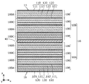
- FIG. 1 is a cross-sectional view showing the cross-sectional structure of a battery 1 according to this embodiment.
- battery 1 includes power generating element 10 , electrode insulating layer 21 , counter electrode insulating layer 22 , counter electrode terminal 31 , electrode terminal 32 , and insulating layer 40 .
- the battery 1 is, for example, an all-solid battery.
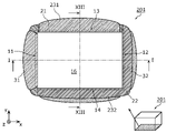
- FIG. 2 is a top view of power generation element 10 of battery 1 according to the present embodiment. 1 shows a cross section taken along line II of FIG.
- the plan view shape of the power generation element 10 is, for example, rectangular as shown in FIG. That is, the shape of the power generation element 10 is a flat rectangular parallelepiped.
- flat means that the thickness (that is, the length in the z-axis direction) is shorter than each side (that is, each length in the x-axis direction and the y-axis direction) or the maximum width of the main surface.
- the plan view shape of the power generation element 10 may be a square, a hexagon, an octagon, or another polygon, or may be a circle, an ellipse, or the like.
- FIG. 1 shows not only a cross-sectional view but also a small perspective view of the schematic shape of the battery 1, and schematically represents the position of the cross section.
- FIG. 1 shows not only a cross-sectional view but also a small perspective view of the schematic shape of the battery 1, and schematically represents the position of the cross section.
- other drawings to be described later may also schematically show perspective views of power generation elements and cross-sectional or lateral positions represented by the respective drawings.
- the power generation element 10 includes four side surfaces 11, 12, 13 and 14 and two main surfaces 15 and 16, as shown in FIGS.
- the side surfaces 11, 12, 13 and 14 and the main surfaces 15 and 16 are all flat surfaces.
- the side 11 is an example of the first side.
- Side 12 is an example of a second side.
- Sides 11 and 12 face away from each other and are parallel to each other.
- Sides 11 and 12 are sides including the short sides of main surface 15 respectively.
- the side 13 is an example of the third side.
- Side 14 is an example of a fourth side.
- Sides 13 and 14 face away from each other and are parallel to each other.
- Sides 13 and 14 are sides including the long sides of main surface 15 respectively.
- the main surfaces 15 and 16 face each other and are parallel to each other.
- the main surface 15 is the top surface of the power generation element 10 .
- the main surface 16 is the bottom surface of the power generation element 10 .
- the power generation element 10 has multiple battery cells 100 .
- the battery cell 100 is a battery with a minimum configuration and is also called a unit cell.
- a plurality of battery cells 100 are electrically connected in parallel and stacked. In this embodiment, all the battery cells 100 included in the power generation element 10 are electrically connected in parallel.
- the number of battery cells 100 included in the power generation element 10 is eight, but the number is not limited to this.
- the number of battery cells 100 included in the power generation element 10 may be an even number such as two or four.
- Each of the plurality of battery cells 100 includes an electrode layer 110, a counter electrode layer 120, and a solid electrolyte layer 130.
- the electrode layer 110 has an electrode current collector 111 and an electrode active material layer 112 .
- the counter electrode layer 120 has a counter electrode current collector 121 and a counter electrode active material layer 122 .
- an electrode current collector 111, an electrode active material layer 112, a solid electrolyte layer 130, a counter electrode active material layer 122 and a counter electrode current collector 121 are laminated in this order along the z-axis. .
- the electrode layer 110 is one of the positive electrode layer and the negative electrode layer of the battery cell 100 .
- the counter electrode layer 120 is the other of the positive electrode layer and the negative electrode layer of the battery cell 100 .
- the electrode layer 110 is a negative electrode layer and the counter electrode layer 120 is a positive electrode layer.
- the configurations of the plurality of battery cells 100 are substantially the same. In two battery cells 100 adjacent to each other, the order of arrangement of each layer constituting the battery cell 100 is reversed. That is, the plurality of battery cells 100 are stacked side by side along the z-axis while the order of the layers constituting the battery cells 100 alternates. In the present embodiment, since the number of battery cells 100 is an even number, the bottom layer and the top layer of power generation element 10 are current collectors of the same polarity.
- a predetermined number of the plurality of battery cells 100 are unitized. Specifically, an even number of battery cells 100 are connected in parallel to form one parallel unit. Layers of the same polarity are positioned at both ends of the parallel unit in the stacking direction.
- power generation element 10 includes parallel units 10A and 10B.
- the parallel unit 10A and the parallel unit 10B are stacked with an insulating layer 40 interposed therebetween.
- the parallel unit 10A is an example of a first parallel unit, and counter electrode layers 120 are positioned at both ends in the stacking direction. Specifically, each of the top layer and the bottom layer of parallel unit 10A is counter electrode current collector 121 of counter electrode layer 120 .
- the parallel unit 10A is a stack consisting of four battery cells 100.
- the battery cell 100 included in the parallel unit 10A is an example of a first battery cell. Since the number of battery cells 100 included in the parallel unit 10A is an even number, the counter electrode layers 120 can be easily arranged at both the upper and lower ends when the layers constituting the battery cells 100 are alternately stacked. can be done.
- the parallel unit 10A is located at one end of the power generation element 10 in the stacking direction (specifically, the end on the negative side of the z-axis). Specifically, the parallel unit 10A is located at the lowest layer of the power generation element 10 .
- the main surface 16, which is the lower surface of the power generation element 10, is the main surface of the counter electrode current collector 121 located at the bottom layer in the parallel unit 10A.
- the parallel unit 10B is an example of a second parallel unit, and electrode layers 110 are positioned at both ends in the stacking direction. Specifically, each of the top layer and bottom layer of the parallel unit 10B is the electrode current collector 111 of the electrode layer 110 .
- the parallel unit 10B is a stack of four battery cells 100. Note that the battery cells 100 included in the parallel unit 10B are an example of second battery cells. Since the number of battery cells 100 included in the parallel unit 10B is an even number, when the layers constituting the battery cells 100 are stacked alternately, the electrode layers 110 can be easily arranged at both the upper and lower ends. can be done.
- the parallel unit 10B is located at the other end in the stacking direction of the power generation element 10 (specifically, the end on the positive side of the z-axis). Specifically, the parallel unit 10B is located on the top layer of the power generation element 10 .
- the main surface 15, which is the upper surface of the power generation element 10, is the main surface of the electrode current collector 111 located in the uppermost layer within the parallel unit 10B.
- the battery cell 100 is likely to warp due to the difference in strength of the current collectors.
- the parallel unit 10A counter electrode current collectors, that is, current collectors of the same polarity are positioned at both ends in the stacking direction. Therefore, the parallel unit 10A is less likely to warp.
- the parallel unit 10B As a result, a large number of parallel units 10A and 10B can be stably stacked, and the capacity energy density can be increased.
- the number of battery cells 100 included in each of parallel units 10A and 10B may be different from each other.
- FIG. 3A is a cross-sectional view of battery cell 100 included in power generation element 10 according to the present embodiment.
- the electrode current collector 111 and the counter electrode current collector 121 are conductive foil-shaped, plate-shaped, or mesh-shaped members, respectively. Each of the electrode current collector 111 and the counter electrode current collector 121 may be, for example, a conductive thin film. As materials for forming the electrode current collector 111 and the counter electrode current collector 121, for example, metals such as stainless steel (SUS), aluminum (Al), copper (Cu), and nickel (Ni) can be used. The electrode current collector 111 and the counter electrode current collector 121 may be formed using different materials.
- each of the electrode current collector 111 and the counter electrode current collector 121 is, for example, 5 ⁇ m or more and 100 ⁇ m or less, but is not limited to this.
- the thickness of each of electrode current collector 111 and counter electrode current collector 121 may be 20 ⁇ m or less.
- the thickness of the current collector is kept small even if the number of parallel connections is increased, contributing to an improvement in energy density. .
- the number of current collectors also increases. Therefore, reducing the thickness of the current collectors is useful for suppressing an increase in the thickness of the power generation element 10 .
- An electrode active material layer 112 is in contact with the main surface of the electrode current collector 111 .
- the electrode current collector 111 may include a current collector layer, which is a layer containing a conductive material and provided in a portion in contact with the electrode active material layer 112 .
- a counter electrode active material layer 122 is in contact with the main surface of the counter electrode current collector 121 .
- the counter electrode current collector 121 may include a current collector layer, which is a layer containing a conductive material and provided in a portion in contact with the counter electrode active material layer 122 .
- the electrode active material layer 112 is arranged on the main surface of the electrode current collector 111 on the counter electrode layer 120 side.
- the electrode active material layer 112 contains, for example, a negative electrode active material as an electrode material.
- the electrode active material layer 112 is arranged to face the counter electrode active material layer 122 .
- a negative electrode active material such as graphite or metallic lithium can be used.
- Various materials capable of extracting and inserting ions such as lithium (Li) or magnesium (Mg) may be used as materials of the negative electrode active material.
- a solid electrolyte such as an inorganic solid electrolyte may be used.
- an inorganic solid electrolyte for example, a sulfide solid electrolyte or an oxide solid electrolyte can be used.
- a sulfide solid electrolyte for example, a mixture of lithium sulfide (Li 2 S) and phosphorus pentasulfide (P 2 S 5 ) can be used.
- a conductive material such as acetylene black or a binding binder such as polyvinylidene fluoride may be used.
- the electrode active material layer 112 is produced by coating the main surface of the electrode current collector 111 with a paste-like paint in which the material contained in the electrode active material layer 112 is kneaded together with a solvent and drying it.
- the electrode layer 110 also referred to as an electrode plate
- the thickness of the electrode active material layer 112 is, for example, 5 ⁇ m or more and 300 ⁇ m or less, but is not limited thereto.
- the counter electrode active material layer 122 is arranged on the main surface of the counter electrode current collector 121 on the electrode layer 110 side.
- the counter electrode active material layer 122 is a layer containing a positive electrode material such as an active material.
- the positive electrode material is the material that constitutes the counter electrode of the negative electrode material.
- the counter electrode active material layer 122 contains, for example, a positive electrode active material.
- Examples of the positive electrode active material contained in the counter electrode active material layer 122 include lithium cobaltate composite oxide (LCO), lithium nickelate composite oxide (LNO), lithium manganate composite oxide (LMO), and lithium-manganese.
- LCO lithium cobaltate composite oxide
- LNO lithium nickelate composite oxide
- LMO lithium manganate composite oxide
- LNMCO lithium-manganese
- LMNO nickel composite oxide
- LMCO lithium-manganese-cobalt composite oxide
- LNCO lithium-nickel-cobalt composite oxide
- LNMCO lithium-nickel-manganese-cobalt composite oxide
- Various materials capable of withdrawing and inserting ions such as Li or Mg can be used as the material of the positive electrode active material.
- a solid electrolyte such as an inorganic solid electrolyte may be used.
- a sulfide solid electrolyte, an oxide solid electrolyte, or the like can be used.
- a sulfide solid electrolyte for example, a mixture of Li2S and P2S5 can be used.
- the surface of the positive electrode active material may be coated with a solid electrolyte.
- a conductive material such as acetylene black or a binding binder such as polyvinylidene fluoride may be used.
- the counter electrode active material layer 122 is produced by applying a paste-like paint in which the material contained in the counter electrode active material layer 122 is kneaded together with a solvent onto the main surface of the counter electrode current collector 121 and drying it.
- the counter electrode layer 120 also referred to as a counter electrode plate
- the thickness of the counter electrode active material layer 122 is, for example, 5 ⁇ m or more and 300 ⁇ m or less, but is not limited thereto.
- the solid electrolyte layer 130 is arranged between the electrode active material layer 112 and the counter electrode active material layer 122 . Solid electrolyte layer 130 is in contact with each of electrode active material layer 112 and counter electrode active material layer 122 .
- Solid electrolyte layer 130 is a layer containing an electrolyte material. As the electrolyte material, generally known battery electrolytes can be used. The thickness of solid electrolyte layer 130 may be 5 ⁇ m or more and 300 ⁇ m or less, or may be 5 ⁇ m or more and 100 ⁇ m or less.
- Solid electrolyte layer 130 contains a solid electrolyte.
- a solid electrolyte such as an inorganic solid electrolyte can be used.
- an inorganic solid electrolyte a sulfide solid electrolyte, an oxide solid electrolyte, or the like can be used.
- a sulfide solid electrolyte for example, a mixture of Li2S and P2S5 can be used.
- the solid electrolyte layer 130 may contain a binding binder such as polyvinylidene fluoride.
- the electrode active material layer 112, the counter electrode active material layer 122, and the solid electrolyte layer 130 are maintained in the form of parallel plates. As a result, it is possible to suppress the occurrence of cracks or collapse due to bending. Note that the electrode active material layer 112, the counter electrode active material layer 122, and the solid electrolyte layer 130 may be combined and smoothly curved.
- the end surface of the counter electrode current collector 121 on the side surface 11 side and the end surface of the electrode layer 110 on the side surface 11 side coincide when viewed from the z-axis direction.
- the end surface of the counter electrode current collector 121 on the side surface 11 side and the end surface of the electrode current collector 111 on the side surface 11 side match when viewed from the z-axis direction. The same applies to the end surfaces of the counter electrode current collector 121 and the electrode current collector 111 on the side surface 12 side.
- electrode current collector 111 electrode active material layer 112, solid electrolyte layer 130, counter electrode active material layer 122, and counter electrode current collector 121 have the same shape and size. , the contours of each match. That is, the shape of the battery cell 100 is a flat rectangular parallelepiped shape.
- two adjacent battery cells 100 share a current collector.
- the battery cell 100 in the bottom layer and the battery cell 100 one above it share the electrode current collector 111 .
- Electrode active material layers 112 are provided on both main surfaces of a shared electrode current collector 111 .
- Two counter electrode layers 120 adjacent to each other share the counter electrode current collector 121 with each other.
- a counter electrode active material layer 122 is provided on both main surfaces of a shared counter electrode current collector 121 .
- Such a battery 1 is formed by combining and stacking not only the battery cell 100 shown in FIG. 3A, but also the battery cells 100B and 100C shown in FIGS. 3B and 3C.
- the battery cell 100 shown in FIG. 3A will be described as a battery cell 100A.
- a battery cell 100B shown in FIG. 3B has a configuration in which the electrode current collector 111 is removed from the battery cell 100A shown in FIG. 3A. That is, the electrode layer 110B of the battery cell 100B consists of the electrode active material layer 112 only.
- a battery cell 100C shown in FIG. 3C has a configuration in which the counter electrode current collector 121 is removed from the battery cell 100A shown in FIG. 3A. That is, the counter electrode layer 120C of the battery cell 100C consists of only the counter electrode active material layer 122. As shown in FIG.
- FIG. 4 is a cross-sectional view showing the power generating element 10 according to this embodiment.
- FIG. 4 is a diagram extracting only the power generation element 10 of FIG.
- the battery cell 100A is arranged in the bottom layer, and the battery cells 100B and 100C are alternately stacked upward. At this time, the battery cell 100B is stacked upside down from the orientation shown in FIG. 3B. Thereby, parallel unit 10A is formed.
- each parallel unit is not limited to this.
- a unit of two battery cells 100 sharing a current collector may be formed by applying double-sided coating to one current collector, and the formed units may be stacked.
- the power generation element 10 As described above, in the power generation element 10 according to the present embodiment, all the battery cells 100 are connected in parallel, and no battery cells connected in series are included. Therefore, when the battery 1 is charged and discharged, non-uniform charging and discharging due to variations in the capacity of the battery cells 100 are less likely to occur. Therefore, the possibility that some of the plurality of battery cells 100 are overcharged or overdischarged can be greatly reduced, and the reliability of the battery 1 can be improved.
- FIG. 5 is a top view of the battery 1 according to this embodiment.
- FIG. 6 is a plan view of the lower surface of battery 1 according to the present embodiment, seen through from above.
- FIG. 7 is a cross-sectional view showing the cross-sectional configuration of the battery 1 along line VIIa-VIIa and line VIIb-VIIb of FIG. 2, FIG. 5 or FIG.
- the cross section along the VIIa-VIIa line is the same as the cross section along the VIIb-VIIb line.
- FIG. 8 is a cross-sectional view showing the cross-sectional structure of the battery taken along line VIII-VIII of FIG. 2, FIG. 5 or FIG.
- FIG. 9 is a side view showing the positional relationship between the side surface 11 of the power generation element 10 and the electrode insulating layer 21 and the counter electrode terminal 31 provided on the side surface 11 according to the present embodiment.
- FIG. 10 is a side view showing the positional relationship between the side surface 12 of the power generating element 10 and the counter electrode insulating layer 22 and the electrode terminal 32 provided on the side surface 12 according to the present embodiment. 9 and 10, the end face of each layer appearing on the side surface 11 or 12 is hatched in the same manner as the layer shown in the cross section of FIG.
- the electrode insulating layer 21 is an example of a first insulating member, and covers the electrode layer 110 on the side surface 11 as shown in FIG. Specifically, the electrode insulating layer 21 completely covers the electrode current collector 111 and the electrode active material layer 112 on the side surface 11 .
- FIG. 9 is a side view of the power generation element 10, and is a plan view of the side surface 11 viewed from the front.
- (b) of FIG. 9 shows the side surface 11 of (a) of FIG. 9 and the electrode insulating layer 21 provided on the side surface 11 .
- FIG. 9B is a side view of the battery 1 of FIG. 1 viewed from the negative side of the x-axis through the counter electrode terminal 31 .
- FIG. 9(c) is a side view of the battery 1 on the side 11 side.
- the electrode insulating layer 21 covers the electrode layer 110 of each of the plurality of battery cells 100 on the side surface 11 .
- the electrode insulating layer 21 does not cover at least part of the counter electrode layer 120 of each of the plurality of battery cells 100 . Therefore, the electrode insulating layer 21 has a striped shape in plan view of the side surface 11 .
- the electrode insulating layer 21 continuously covers the electrode layers 110 of the two adjacent battery cells 100 . Specifically, the electrode insulating layer 21 extends from at least a portion of one solid electrolyte layer 130 of two adjacent battery cells 100 to at least a portion of the other solid electrolyte layer 130 of two adjacent battery cells 100. are continuously covered.
- the electrode insulating layer 21 covers at least part of the solid electrolyte layer 130 on the side surface 11 . Specifically, when the side surface 11 is viewed in plan, the contour of the electrode insulating layer 21 overlaps the solid electrolyte layer 130 . As a result, even if the width (the length in the z-axis direction) varies due to manufacturing variations in the electrode insulating layer 21, the possibility of exposing the electrode layer 110 is reduced. Therefore, short-circuiting between the electrode layer 110 and the counter electrode layer 120 via the counter electrode terminal 31 formed to cover the electrode insulating layer 21 can be suppressed. Further, the end surface of the solid electrolyte layer 130 made of a powdery material has very fine unevenness. For this reason, the electrode insulating layer 21 enters into the irregularities, thereby improving the adhesion strength of the electrode insulating layer 21 and improving the insulation reliability.
- electrode insulating layer 21 may cover all of solid electrolyte layer 130 on side surface 11 . Specifically, the contour of the electrode insulating layer 21 may overlap the boundary between the solid electrolyte layer 130 and the counter electrode active material layer 122 . It should be noted that it is not essential that the electrode insulating layer 21 partially cover the solid electrolyte layer 130 . For example, the contour of the electrode insulating layer 21 may overlap the boundary between the solid electrolyte layer 130 and the electrode active material layer 112 .
- the electrode insulating layer 21 partially covers the insulating layer 40 on the side surface 11, it is not limited to this.
- the electrode insulating layer 21 may cover the entire insulating layer 40 on the side surface 11 as long as the uppermost counter electrode current collector 121 of the parallel unit 10A is exposed. Further, the electrode insulating layer 21 may completely expose the insulating layer 40 on the side surface 11 as long as it completely covers the lowermost electrode current collector 111 of the parallel unit 10B.
- the electrode insulating layer 21 is provided along the z-axis direction at the end of the side surface 11 in the y-axis direction, in addition to the stripe-shaped portion.
- the shape of the electrode insulating layer 21 may be a ladder shape in a plan view of the side surface 11 .
- the electrode insulating layer 21 may partially cover the counter electrode current collector 121 .
- the electrode insulating layer 21 covers from the bottom layer to the top layer at the end of the side surface 11 in the y-axis direction.
- the electrode insulating layer 21 is provided not only on the side surface 11 but also on the side surface 13 as shown in FIGS. As shown in FIG. 8 , electrode insulating layer 21 provided on side surface 13 covers not only electrode layer 110 , but also solid electrolyte layer 130 , counter electrode layer 120 , and insulating layer 40 . Specifically, the electrode insulating layer 21 covers the entire side surface 13 . The portion provided on the side surface 13 of the electrode insulating layer 21 is an example of the third insulating member.
- the electrode current collector 111 is the uppermost layer of the power generation element 10, as shown in FIG. It covers part of the main surface. The same applies to the vicinity of the upper end of the side surface 13 .
- the electrode insulating layer 21 is strong against an external force in the z-axis direction, and detachment is suppressed.
- the counter electrode terminal 31 wraps around the main surface 15 of the power generation element 10, it can be prevented from coming into contact with the electrode current collector 111 and causing a short circuit.
- the reliability of battery 1 can be enhanced.
- the bottom layer of the power generation element 10 is the counter electrode current collector 121 . Therefore, as shown in FIG. 6, the electrode insulating layer 21 does not cover the counter electrode current collector 121 near the lower ends of the side surfaces 11 except for both ends in the y-axis direction. Thereby, the connection between the counter electrode terminal 31 and the main surface of the counter electrode current collector 121 can be ensured. Further, the electrode insulating layer 21 covers the counter electrode current collector 121 near the lower end of the side surface 13 . As a result, the electrode insulating layer 21 is strong against an external force in the z-axis direction, and detachment is suppressed.
- the counter electrode insulating layer 22 is an example of a second insulating member, and covers the counter electrode layer 120 on the side surface 12 as shown in FIG. Specifically, counter electrode insulating layer 22 completely covers counter electrode current collector 121 and counter electrode active material layer 122 on side surface 12 .
- FIG. 10 is a side view of the power generating element 10, and is a plan view of the side surface 12 viewed from the front.
- (b) of FIG. 10 shows the side surface 12 of (a) of FIG. 10 and the counter electrode insulating layer 22 provided on the side surface 12 . That is, FIG. 10(b) is a side view of the battery 1 of FIG. 1 viewed from the positive side of the x-axis with the electrode terminal 32 seen through.
- FIG. 10(c) is a side view of the battery 1 on the side 12 side.
- the counter electrode insulating layer 22 covers the counter electrode layer 120 of each of the plurality of battery cells 100 on the side surface 12 .
- the counter electrode insulating layer 22 does not cover at least part of each electrode layer 110 of the plurality of battery cells 100 . Therefore, the counter electrode insulating layer 22 has a striped shape in plan view of the side surface 12 .
- the counter electrode insulating layer 22 continuously covers the counter electrode layers 120 of the two adjacent battery cells 100 .
- the counter electrode insulating layer 22 extends from at least a portion of one solid electrolyte layer 130 of two adjacent battery cells 100 to at least a portion of the other solid electrolyte layer 130 of two adjacent battery cells 100. are continuously covered.
- the counter electrode insulating layer 22 covers at least part of the solid electrolyte layer 130 on the side surface 12 .
- the outline of the counter electrode insulating layer 22 overlaps the solid electrolyte layer 130 when the side surface 12 is viewed in plan.
- the width the length in the z-axis direction
- the possibility of exposing the counter electrode layer 120 is reduced. Therefore, short circuit between the counter electrode layer 120 and the electrode layer 110 via the electrode terminal 32 formed to cover the counter electrode insulating layer 22 can be suppressed.
- the counter electrode insulating layer 22 enters the unevenness of the end surface of the solid electrolyte layer 130, the adhesion strength of the counter electrode insulating layer 22 is improved, and the insulation reliability is improved.
- the counter electrode insulating layer 22 may cover the entire solid electrolyte layer 130 on the side surface 12 .
- the contour of the counter electrode insulating layer 22 may overlap the boundary between the solid electrolyte layer 130 and the electrode active material layer 112 .
- the contour of the counter electrode insulating layer 22 may overlap the boundary between the solid electrolyte layer 130 and the counter electrode active material layer 122 .
- the counter electrode insulating layer 22 partially covers the insulating layer 40 on the side surface 12, it is not limited to this.
- the counter electrode insulating layer 22 may expose the entire insulating layer 40 on the side surface 12 as long as it covers the uppermost counter electrode current collector 121 of the parallel unit 10A.
- the counter electrode insulating layer 22 may cover the entire insulating layer 40 on the side surface 12 as long as the lowermost electrode current collector 111 of the parallel unit 10B is exposed.
- the counter electrode insulating layer 22 is provided along the z-axis direction at the end of the side surface 12 in the y-axis direction, in addition to the stripe-shaped portion.
- the shape of the counter electrode insulating layer 22 may be a ladder shape in a plan view of the side surface 12 .
- the counter electrode insulating layer 22 may partially cover the electrode current collector 111 .
- the end of the side surface 12 in the y-axis direction is covered with the counter electrode insulating layer 22 from the bottom layer to the top layer.
- the counter electrode insulating layer 22 is provided not only on the side surface 12 but also on the side surface 14 as shown in FIGS. As shown in FIG. 8 , counter electrode insulating layer 22 provided on side surface 14 covers not only counter electrode layer 120 , but also solid electrolyte layer 130 , electrode layer 110 , and insulating layer 40 . Specifically, the counter electrode insulating layer 22 covers the entire side surface 14 . The portion provided on the side surface 14 of the counter electrode insulating layer 22 is an example of the fourth insulating member.
- the bottom layer of the power generating element 10 is the counter electrode current collector 121, as shown in FIG. It covers part of the main surface. The same applies to the vicinity of the lower end of the side surface 14 .
- the counter electrode insulating layer 22 is strong against an external force in the z-axis direction, and detachment is suppressed.
- the electrode terminal 32 wraps around the main surface 16 of the power generation element 10, it can be prevented from coming into contact with the counter electrode current collector 121 and causing a short circuit.
- the reliability of battery 1 can be enhanced.
- the top layer of the power generation element 10 is the electrode current collector 111 . Therefore, as shown in FIG. 5, the counter electrode insulating layer 22 does not cover the electrode current collector 111 near the upper end of the side surface 12 except for both ends in the y-axis direction. Thereby, the connection between the electrode terminal 32 and the main surface of the electrode current collector 111 can be ensured.
- the present invention is not limited to this.
- one of the electrode insulating layer 21 and the counter electrode insulating layer 22 may cover three sides.
- at least one of side surfaces 13 and 14 may be covered with both electrode insulating layer 21 and counter electrode insulating layer 22 .
- the electrode insulating layer 21 and the counter electrode insulating layer 22 are each formed using an electrically insulating insulating material.
- the electrode insulating layer 21 and the counter electrode insulating layer 22 each contain resin.
- the resin is, for example, an epoxy resin, but is not limited to this.
- An inorganic material may be used as the insulating material. Usable insulating materials are selected based on various properties such as flexibility, gas barrier properties, impact resistance, and heat resistance.
- the electrode insulating layer 21 and the counter electrode insulating layer 22 are formed using the same material, but may be formed using different materials.
- the electrode insulating layer 21 and the counter electrode insulating layer 22 may be integrally formed of the same material. That is, the boundary between the electrode insulating layer 21 and the counter electrode insulating layer 22 may not be clearly distinguished. Moreover, the electrode insulating layer 21 covers only the side surface 11 and may not be provided on the side surface 13 . Also, the counter electrode insulating layer 22 covers only the side surface 12 and may not be provided on the side surface 14 . Moreover, the insulating layer provided on the side surface 13 may be formed using a material different from that of both the electrode insulating layer 21 and the counter electrode insulating layer 22 . The same applies to the insulating layer provided on the side surface 14 .
- the counter electrode terminal 31 is an example of a first terminal electrode, which covers the side surface 11 and the electrode insulating layer 21 and is electrically connected to the counter electrode layer 120 as shown in FIG. Specifically, the counter electrode terminal 31 covers the electrode insulating layer 21 and the portion of the side surface 11 that is not covered with the electrode insulating layer 21 .
- the counter electrode terminal 31 is in contact with the end surfaces of the counter electrode current collector 121 and the counter electrode active material layer 122 and is electrically connected to the counter electrode layer 120 . Since the counter electrode active material layer 122 is made of a powdery material, it has very fine irregularities like the solid electrolyte layer 130 . By inserting the counter electrode terminal 31 into the unevenness of the end surface of the counter electrode active material layer 122, the adhesion strength of the counter electrode terminal 31 is improved, and the reliability of electrical connection is improved.
- the counter electrode terminal 31 is electrically connected to the counter electrode layer 120 of each of the plurality of battery cells 100 .
- the counter electrode terminal 31 has a part of the function of electrically connecting the battery cells 100 in parallel.
- the counter electrode terminal 31 covers almost the entire side surface 11 collectively.
- the counter electrode terminal 31 functions as the positive electrode of the battery 1 .
- the counter electrode terminal 31 partially covers the main surface of the counter electrode current collector 121 located in the bottom layer.
- the counter electrode terminal 31 is strong against an external force in the z-axis direction, and detachment is suppressed.
- the contact area between the counter electrode terminal 31 and the counter electrode current collector 121 is increased, the connection resistance between the counter electrode terminal 31 and the counter electrode current collector 121 is reduced, and the large current characteristics can be improved. For example, rapid charging of the battery 1 becomes possible.
- the electrode terminal 32 is an example of a second terminal electrode, which covers the side surface 12 and the counter electrode insulating layer 22 and is electrically connected to the electrode layer 110 as shown in FIG. Specifically, the electrode terminal 32 covers the counter electrode insulating layer 22 and the portion of the side surface 12 that is not covered with the counter electrode insulating layer 22 .
- electrode terminal 32 is in contact with the end surfaces of electrode current collector 111 and electrode active material layer 112 and is electrically connected to electrode layer 110 . Since the electrode active material layer 112 is made of a powdery material, it has very fine irregularities like the solid electrolyte layer 130 . Since the electrode terminal 32 enters the unevenness of the end surface of the electrode active material layer 112, the adhesion strength of the electrode terminal 32 is improved, and the reliability of electrical connection is improved.
- the electrode terminal 32 is electrically connected to the electrode layer 110 of each of the plurality of battery cells 100 .
- the electrode terminals 32 have a part of the function of electrically connecting the battery cells 100 in parallel.
- the electrode terminals 32 collectively cover substantially the entire side surface 12 . Since the electrode layer 110 is the negative electrode in the present embodiment, the electrode terminal 32 functions as the negative electrode of the battery 1 .
- the electrode terminal 32 partially covers the main surface of the electrode current collector 111 located in the uppermost layer. As a result, the electrode terminal 32 is strong against an external force in the z-axis direction, and detachment is suppressed. In addition, since the contact area between the electrode terminal 32 and the electrode current collector 111 is increased, the connection resistance between the electrode terminal 32 and the electrode current collector 111 is reduced, and large current characteristics can be improved.
- the counter electrode terminal 31 and the electrode terminal 32 are formed using a conductive resin material or the like. Alternatively, the counter electrode terminal 31 and the electrode terminal 32 may be formed using a metal material such as solder. Conductive materials that can be used are selected based on various properties such as flexibility, gas barrier properties, impact resistance, heat resistance, and solder wettability. The counter electrode terminal 31 and the electrode terminal 32 are made of the same material, but may be made of different materials.
- the counter electrode terminal 31 and the electrode terminal 32 not only function as the positive electrode or the negative electrode of the battery 1, but also have the function of connecting the plurality of battery cells 100 in parallel.
- the counter electrode terminal 31 and the electrode terminal 32 are formed so as to closely cover the side surfaces 11 and 12 of the power generation element 10, respectively, so that their volumes can be reduced. That is, since the volume of the terminal electrode is smaller than that of the conventionally used current collecting tab electrode, the energy density per unit volume of the battery 1 can be improved.
- the insulating layer 40 is positioned between the parallel unit 10A and the parallel unit 10B.
- the insulating layer 40 is provided to prevent the parallel unit 10A and the parallel unit 10B from being electrically connected in series. Specifically, the insulating layer 40 suppresses contact between the counter electrode current collector 121 located in the uppermost layer of the parallel unit 10A and the electrode current collector 111 located in the lowermost layer of the parallel unit 10B. to prevent it from being physically connected.
- the size and shape of the insulating layer 40 in plan view are the same as the current collector with which the insulating layer 40 contacts.
- the end face of insulating layer 40 and the end face of each of parallel units 10A and 10B are flush with each other.
- each of the sides 11, 12, 13 and 14 are flat surfaces.
- the end face of the insulating layer 40 may recede from the end faces of the parallel units 10A and 10B.
- a gap is formed between the parallel unit 10A and the parallel unit 10B.
- the electrode insulating layer 21 and the counter electrode insulating layer 22 enter into the gap. Thereby, each of the electrode insulating layer 21 and the counter electrode insulating layer 22 can be fixed more firmly.
- the insulating layer 40 is formed using an insulating resin material, for example.
- the insulating layer 40, the electrode insulating layer 21, and the counter electrode insulating layer 22 may all be formed using the same material.
- the insulating layer 40 may be formed using an inorganic material such as an insulating metal oxide film.
- the insulating layer 40 may be a metal plate having an insulating film formed on one side or both sides of the insulating layer 40 as long as the upper and lower surfaces are insulated.
- the two parallel units 10A and 10B having layers with different polarities exposed on the upper and lower surfaces can be stacked without being connected in series.
- layers with different polarities are positioned between the top layer and the bottom layer of the power generation element 10 .
- the top layer and the bottom layer of the power generation element 10 can be used for electrode extraction, respectively.
- the battery according to Embodiment 2 differs from the battery according to Embodiment 1 in that the electrode terminal and the counter electrode terminal are provided on two sides of the power generation element 10 respectively.
- the following description focuses on the differences from the first embodiment, and omits or simplifies the description of the common points.
- FIG. 11 is a top view of battery 201 according to the present embodiment.
- FIG. 12 is a plan view of the lower surface of battery 201 according to the present embodiment as seen through from above.
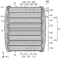
- FIG. 13 is a cross-sectional view showing the cross-sectional structure of battery 201 according to the present embodiment.
- FIG. 13 represents a cross section along line XIII-XIII of FIG. 11 or FIG.
- a battery 201 according to the present embodiment includes a counter electrode terminal 231 and an electrode terminal 232 in addition to the counter electrode terminal 31 and the electrode terminal 32 as compared with the battery 1 shown in FIGS.
- the counter electrode terminal 231 is an example of a third terminal electrode, covers the side surface 13 and the electrode insulating layer 21 , and is connected to the counter electrode layer 120 .
- Counter electrode terminal 231 has the same configuration as counter electrode terminal 31 as shown in FIG. In addition, the counter electrode terminal 231 and the counter electrode terminal 31 are connected and may be integrated.
- the electrode terminal 232 is an example of a fourth terminal electrode, covers the side surface 14 and the counter electrode insulating layer 22 , and is connected to the electrode layer 110 . Electrode terminal 232 has the same configuration as electrode terminal 32 as shown in FIG. In addition, the electrode terminal 232 and the electrode terminal 32 are connected and may be integrated.
- terminals of the same polarity may be provided on two opposing side surfaces instead of two adjacent side surfaces.
- side surfaces 11 and 12 may be provided with counter electrode terminals 31 and 231, respectively
- side surfaces 13 and 14 may be provided with electrode terminals 32 and 232, respectively.
- the battery according to Embodiment 3 differs from the battery according to Embodiment 1 in that it further includes a sealing member and a contact portion.
- a sealing member and a contact portion.
- FIG. 14 is a cross-sectional view showing the cross-sectional structure of the battery 301 according to this embodiment.
- battery 301 includes sealing member 350 , electrode contact 361 , and counter electrode contact 362 in addition to the structure of battery 1 according to Embodiment 1.
- FIG. 14 is a cross-sectional view showing the cross-sectional structure of the battery 301 according to this embodiment.
- battery 301 includes sealing member 350 , electrode contact 361 , and counter electrode contact 362 in addition to the structure of battery 1 according to Embodiment 1.
- FIG. 14 is a cross-sectional view showing the cross-sectional structure of the battery 301 according to this embodiment.
- sealing member 350 As shown in FIG. 14 , battery 301 includes sealing member 350 , electrode contact 361 , and counter electrode contact 362 in addition to the structure of battery 1 according to Embodiment 1.
- electrode contact 361 includes sealing member 350 , electrode contact 361 , and counter electrode contact 362 in addition to the structure of battery 1 according to Embodiment 1.
- the sealing member 350 exposes at least part of the main surface of the power generation element 10 and seals the power generation element 10 . Specifically, the sealing member 350 exposes a portion of the lowermost surface of the parallel unit 10A and a portion of the uppermost surface of the parallel unit 10B, and covers the other portions.
- the sealing member 350 is formed using, for example, an electrically insulating insulating material.
- a generally known battery sealing member material such as a sealing agent can be used.
- a resin material can be used as the insulating material.
- the insulating material may be a material that is insulating and does not have ionic conductivity.
- the insulating material may be at least one of epoxy resin, acrylic resin, polyimide resin, and silsesquioxane.
- sealing member 350 may include a plurality of different insulating materials.
- sealing member 350 may have a multilayer structure. Each layer of the multilayer structure may be formed using different materials and have different properties.
- the sealing member 350 may contain a particulate metal oxide material.
- metal oxide materials silicon oxide, aluminum oxide, titanium oxide, zinc oxide, cerium oxide, iron oxide, tungsten oxide, zirconium oxide, calcium oxide, zeolite, glass, and the like can be used.
- the sealing member 350 may be formed using a resin material in which a plurality of particles made of a metal oxide material are dispersed.
- the particle size of the metal oxide material should be equal to or smaller than the space between the electrode current collector 111 and the counter electrode current collector 121 .
- the particle shape of the metal oxide material is, for example, spherical, ellipsoidal, or rod-like, but is not limited thereto.
- the reliability of the battery 301 can be improved in various aspects such as mechanical strength, short-circuit prevention, and moisture resistance.
- An electrode contact 361 is connected to a portion of the main surface 15 of the power generation element 10 that is not covered with the sealing member 350 .
- a counter electrode contact 362 is connected to a portion of the main surface 16 of the power generating element 10 that is not covered with the sealing member 350 .
- the electrode contacts 361 are electrically connected by coming into contact with the electrode current collectors 111 located on the uppermost layer of the parallel unit 10B.
- the electrode contact 361 is an example of one polarity extraction electrode of the power generation element 10 .
- the counter electrode contact 362 is electrically connected by contacting the counter electrode current collector 121 located at the bottom layer of the parallel unit 10A.
- the counter electrode contact 362 is an example of the extraction electrode of the other polarity of the power generation element 10 .
- the power generation element 10 is shown elongated in the thickness direction, but in reality the shape of the power generation element 10 is flat. That is, the areas of the main surfaces 15 and 16 of the power generating element 10 are larger than the areas of the side surfaces of the power generating element 10 . Therefore, by connecting the contacts to the main surfaces 15 and 16, a strong and stable connection and a low connection resistance are realized.
- the range of the insulating layer covering the side surface is different compared to each embodiment.
- differences from each embodiment will be mainly described, and descriptions of common points will be omitted or simplified.
- FIG. 15 is a cross-sectional view showing the cross-sectional structure of a battery 401 according to a modification.
- battery 401 includes electrode insulating layer 421 and counter electrode insulating layer 422 instead of electrode insulating layer 21 and counter electrode insulating layer 22 , as compared with battery 1 according to Embodiment 1.
- FIG. 1 is a cross-sectional view showing the cross-sectional structure of a battery 401 according to a modification.
- battery 401 includes electrode insulating layer 421 and counter electrode insulating layer 422 instead of electrode insulating layer 21 and counter electrode insulating layer 22 , as compared with battery 1 according to Embodiment 1.
- the electrode insulating layer 421 covers not only the electrode layer 110 but also part of the solid electrolyte layer 130 and the counter electrode layer 120 on the side surface 11, as shown in FIG. That is, the electrode insulating layer 421 covers from the electrode layer 110 to part of the counter electrode layer 120 . Specifically, the electrode insulating layer 421 partially covers the counter electrode active material layer 122 . In this modification, the electrode insulating layer 421 extends from at least part of the counter electrode active material layer 122 of one of the two adjacent battery cells 100 to at least part of the other counter electrode active material layer 122 of the two adjacent battery cells 100. It covers continuously up to the part.
- the electrode insulating layer 421 completely covers one electrode current collector 111 , the electrode active material layers 112 located on both sides of the one electrode current collector 111 , and the two solid electrolyte layers 130 .
- the contour of the electrode insulating layer 421 overlaps the counter electrode active material layer 122 .
- the width (the length in the z-axis direction) fluctuates due to manufacturing variations in the electrode insulating layer 421, the risk of the electrode layer 110 being exposed is extremely low. Therefore, short-circuiting between the electrode layer 110 and the counter electrode layer 120 via the counter electrode terminal 31 can be suppressed.
- the electrode insulating layer 421 enters the unevenness of the end face of the counter electrode active material layer 122, the adhesion strength of the electrode insulating layer 421 is improved, and the insulation reliability is improved.
- the electrode insulating layer 421 may cover the entire counter electrode active material layer 122 on the side surface 11 . Specifically, the contour of the electrode insulating layer 421 may overlap the boundary between the counter electrode active material layer 122 and the counter electrode current collector 121 .
- the counter electrode insulating layer 422 also has the same configuration on the side surface 12 . Specifically, on side surface 12 , counter electrode insulating layer 422 covers not only counter electrode layer 120 but also solid electrolyte layer 130 and part of electrode layer 110 . That is, the counter electrode insulating layer 422 covers from the counter electrode layer 120 to part of the electrode layer 110 . Specifically, the counter electrode insulating layer 422 partially covers the electrode active material layer 112 . In this modification, the counter electrode insulating layer 422 extends from at least part of the electrode active material layer 112 of one of the two adjacent battery cells 100 to at least part of the electrode active material layer 112 of the other of the two adjacent battery cells 100. It covers continuously up to the part. For example, the counter electrode insulating layer 422 completely covers one counter electrode current collector 121 , the counter electrode active material layers 122 located on both sides of the one counter electrode current collector 121 , and the two solid electrolyte layers 130 .
- the outline of the counter electrode insulating layer 422 overlaps the electrode active material layer 112 when the side surface 12 is viewed in plan.
- the width (the length in the z-axis direction) of the counter electrode insulating layer 422 fluctuates due to manufacturing variations, the possibility of exposing the counter electrode layer 120 is extremely low. Therefore, short-circuiting between the counter electrode layer 120 and the electrode layer 110 via the electrode terminal 32 can be suppressed.
- the counter electrode insulating layer 422 enters the irregularities of the end surface of the electrode active material layer 112, the adhesion strength of the counter electrode insulating layer 422 is improved, and the insulation reliability is improved.
- the counter electrode insulating layer 422 may cover the entire electrode active material layer 112 on the side surface 12 . Specifically, the contour of the counter electrode insulating layer 422 may overlap the boundary between the electrode active material layer 112 and the electrode current collector 111 .
- FIG. 15 shows a modification of the battery 1 according to Embodiment 1
- the electrode insulating layer 421 and the counter electrode insulating layer 422 may be applied to the batteries according to the above embodiments. In either case, similarly to battery 401, the possibility of short-circuiting between electrode layer 110 and counter electrode layer 120 can be sufficiently reduced, so that the reliability of the battery can be enhanced.
- FIG. 16 is a flow chart showing an example of a method for manufacturing a battery according to each embodiment or modification. An example of the battery 1 will be described below.
- a plurality of battery cells are prepared (S10, first step).
- the prepared battery cells are, for example, the battery cells 100A, 100B and 100C shown in FIGS. 3A to 3C.
- the parallel unit 10A is formed by stacking an even number of battery cells 100 so that the counter electrode layers 120 are positioned at both ends in the stacking direction.
- parallel unit 10B is formed by stacking an even number of battery cells 100 so that electrode layers 110 are positioned at both ends in the stacking direction.
- Parallel units 10A and 10B are respectively formed by appropriately combining and stacking battery cells 100A, 100B and 100C.
- the insulating layer 40 is arranged on the main surface of at least one of the parallel units 10A and 10B (S30).
- the insulating layer 40 is arranged on the main surface of the counter electrode current collector 121 of the parallel unit 10A.
- the insulating layer 40 to be placed is, for example, an insulating adhesive before curing.
- the insulating layer 40 is arranged by an inkjet method, a spray method, a screen printing method, a gravure printing method, or the like.
- the parallel units 10A and 10B are stacked with the insulating layer 40 interposed therebetween (S40). After lamination, the insulating layer 40 is cured as necessary.
- the above steps S20 to S40 are an example of the second step.
- the power generation element 10, which is a laminate of the parallel units 10A and 10B, is formed.
- the side surface of the power generation element 10 may be flattened.
- the power generating element 10 having flat side surfaces can be formed. Side flattening may be performed for each parallel unit. The cutting process is performed by, for example, a knife, laser or jet.
- an insulating layer is formed on the side surface of the power generation element 10 (S50, third step). Specifically, the electrode insulating layer 21 covering the electrode layer 110 is formed on the side surface 11 . Also, a counter electrode insulating layer 22 covering the counter electrode layer 120 is formed on the side surface 12 .
- the electrode insulating layer 21 and the counter electrode insulating layer 22 are formed, for example, by coating and curing a fluid resin material. Coating is performed by an inkjet method, a spray method, a screen printing method, a gravure printing method, or the like. Curing is performed by drying, heating, light irradiation, or the like, depending on the resin material used.
- a tape or the like is applied to a region where the insulating layer should not be formed so that the end surface of the counter electrode current collector 121 and the end surface of the electrode current collector 111 are not insulated.
- a treatment for forming the protective member may be performed by masking or resist treatment with .
- an extraction terminal is formed on the side surface of the power generation element 10 (S60, fourth step). Specifically, a counter electrode terminal 31 that electrically connects the plurality of counter electrode layers 120 is formed on the side surface 11 . Electrode terminals 32 for electrically connecting the electrode layers 110 are formed on the side surface 12 .
- the counter electrode terminal 31 is formed by applying a conductive resin so as to cover the electrode insulating layer 21 and the portion of the side surface 11 not covered by the electrode insulating layer 21 and curing the resin.
- the electrode terminal 32 is arranged by applying a conductive resin so as to cover the counter electrode insulating layer 22 and the portion of the side surface 12 not covered with the counter electrode insulating layer 22 and curing the resin.
- the counter electrode terminal 31 and the electrode terminal 32 may be formed by, for example, printing, plating, vapor deposition, sputtering, welding, soldering, joining, or other methods.
- the battery 1 shown in FIG. 1 can be manufactured.
- a step of pressing the plurality of battery cells 100 prepared in step S10 in the stacking direction may be performed individually or after stacking the plurality of battery cells.
- the sealing member 350 shown in FIG. 10 may be formed after forming the extraction terminals (S60).
- the sealing member 350 is formed, for example, by coating and curing a resin material having fluidity. Coating is performed by an inkjet method, a spray method, a screen printing method, a gravure printing method, or the like. Curing is performed by drying, heating, light irradiation, or the like, depending on the resin material used.
- terminal electrodes may be provided on each of the side surfaces 13 and 14 . That is, the side surface 13 may be an example of the first side surface, and the side surface 14 may be an example of the second side surface. Terminal electrodes may be provided on each of one of side surfaces 11 and 12 and one of side surfaces 13 and 14 . That is, the terminal electrodes may be provided along two adjacent sides of the main surface 15 .
- the power generation element 10 may include three or more parallel units. At this time, current collectors of the same polarity may be positioned on the top layer and the bottom layer of the power generating element 10 .
- the number of battery cells 100 included in parallel units 10A and 10B may be different from each other. Also, the power generation element 10 may include three or more parallel units.
- a battery cell 100 may be arranged instead of the insulating layer 40 between the parallel unit 10A and the parallel unit 10B.
- the electrode insulating layer 21 has a portion that covers from the bottom layer to the top layer along the side of the side surface 11 in the stacking direction, but is not limited to this.
- the electrode insulating layer 21 may have only stripe-shaped portions when the side surface 11 is viewed in plan. Specifically, the electrode insulating layer 21 may not cover the counter electrode layer 120 or the counter electrode current collector 121 on the side surface 11 at all. The same applies to the counter electrode insulating layer 22 .
- an external electrode may be formed on the outermost surface of each of the electrode terminal and the counter electrode terminal by a method such as plating, printing, or soldering.
- each battery has both the counter electrode terminal 31 and the electrode terminal 32, but may have only one. That is, one of the positive electrode and the negative electrode of the battery may be taken out by a tab electrode.
- the present disclosure can be used, for example, as batteries for electronic equipment, electric appliance devices, electric vehicles, and the like.
Landscapes
- Chemical & Material Sciences (AREA)
- Chemical Kinetics & Catalysis (AREA)
- Electrochemistry (AREA)
- General Chemical & Material Sciences (AREA)
- Engineering & Computer Science (AREA)
- Manufacturing & Machinery (AREA)
- Connection Of Batteries Or Terminals (AREA)
Priority Applications (4)
| Application Number | Priority Date | Filing Date | Title |
|---|---|---|---|
| JP2023520902A JPWO2022239528A1 (https=) | 2021-05-10 | 2022-03-25 | |
| EP22807233.6A EP4340092A4 (en) | 2021-05-10 | 2022-03-25 | BATTERY AND METHOD FOR MANUFACTURING THE BATTERY |
| CN202280033198.6A CN117280518A (zh) | 2021-05-10 | 2022-03-25 | 电池及电池的制造方法 |
| US18/504,076 US20240072392A1 (en) | 2021-05-10 | 2023-11-07 | Battery and method of manufacturing battery |
Applications Claiming Priority (2)
| Application Number | Priority Date | Filing Date | Title |
|---|---|---|---|
| JP2021-080037 | 2021-05-10 | ||
| JP2021080037 | 2021-05-10 |
Related Child Applications (1)
| Application Number | Title | Priority Date | Filing Date |
|---|---|---|---|
| US18/504,076 Continuation US20240072392A1 (en) | 2021-05-10 | 2023-11-07 | Battery and method of manufacturing battery |
Publications (1)
| Publication Number | Publication Date |
|---|---|
| WO2022239528A1 true WO2022239528A1 (ja) | 2022-11-17 |
Family
ID=84029562
Family Applications (1)
| Application Number | Title | Priority Date | Filing Date |
|---|---|---|---|
| PCT/JP2022/014306 Ceased WO2022239528A1 (ja) | 2021-05-10 | 2022-03-25 | 電池および電池の製造方法 |
Country Status (5)
| Country | Link |
|---|---|
| US (1) | US20240072392A1 (https=) |
| EP (1) | EP4340092A4 (https=) |
| JP (1) | JPWO2022239528A1 (https=) |
| CN (1) | CN117280518A (https=) |
| WO (1) | WO2022239528A1 (https=) |
Cited By (1)
| Publication number | Priority date | Publication date | Assignee | Title |
|---|---|---|---|---|
| WO2023223578A1 (ja) * | 2022-05-18 | 2023-11-23 | パナソニックIpマネジメント株式会社 | デバイスおよびデバイスの製造方法 |
Citations (4)
| Publication number | Priority date | Publication date | Assignee | Title |
|---|---|---|---|---|
| JP2004273436A (ja) * | 2003-02-18 | 2004-09-30 | Matsushita Electric Ind Co Ltd | 全固体薄膜積層電池 |
| JP2008198492A (ja) | 2007-02-13 | 2008-08-28 | Namics Corp | 全固体二次電池 |
| JP2013120717A (ja) | 2011-12-08 | 2013-06-17 | Toyota Motor Corp | 全固体電池 |
| WO2019139070A1 (ja) * | 2018-01-10 | 2019-07-18 | Tdk株式会社 | 全固体リチウムイオン二次電池 |
Family Cites Families (2)
| Publication number | Priority date | Publication date | Assignee | Title |
|---|---|---|---|---|
| EP4216333A4 (en) * | 2020-09-18 | 2024-12-25 | Panasonic Intellectual Property Management Co., Ltd. | Battery and laminated battery |
| JP2023172252A (ja) * | 2022-05-23 | 2023-12-06 | パナソニックIpマネジメント株式会社 | 電池の製造方法および電池 |
-
2022
- 2022-03-25 EP EP22807233.6A patent/EP4340092A4/en active Pending
- 2022-03-25 WO PCT/JP2022/014306 patent/WO2022239528A1/ja not_active Ceased
- 2022-03-25 JP JP2023520902A patent/JPWO2022239528A1/ja active Pending
- 2022-03-25 CN CN202280033198.6A patent/CN117280518A/zh active Pending
-
2023
- 2023-11-07 US US18/504,076 patent/US20240072392A1/en active Pending
Patent Citations (4)
| Publication number | Priority date | Publication date | Assignee | Title |
|---|---|---|---|---|
| JP2004273436A (ja) * | 2003-02-18 | 2004-09-30 | Matsushita Electric Ind Co Ltd | 全固体薄膜積層電池 |
| JP2008198492A (ja) | 2007-02-13 | 2008-08-28 | Namics Corp | 全固体二次電池 |
| JP2013120717A (ja) | 2011-12-08 | 2013-06-17 | Toyota Motor Corp | 全固体電池 |
| WO2019139070A1 (ja) * | 2018-01-10 | 2019-07-18 | Tdk株式会社 | 全固体リチウムイオン二次電池 |
Non-Patent Citations (1)
| Title |
|---|
| See also references of EP4340092A4 |
Cited By (1)
| Publication number | Priority date | Publication date | Assignee | Title |
|---|---|---|---|---|
| WO2023223578A1 (ja) * | 2022-05-18 | 2023-11-23 | パナソニックIpマネジメント株式会社 | デバイスおよびデバイスの製造方法 |
Also Published As
| Publication number | Publication date |
|---|---|
| EP4340092A4 (en) | 2025-06-25 |
| JPWO2022239528A1 (https=) | 2022-11-17 |
| US20240072392A1 (en) | 2024-02-29 |
| CN117280518A (zh) | 2023-12-22 |
| EP4340092A1 (en) | 2024-03-20 |
Similar Documents
| Publication | Publication Date | Title |
|---|---|---|
| CN113302773B (zh) | 层叠电池 | |
| JP7437710B2 (ja) | 積層電池 | |
| WO2022172619A1 (ja) | 電池および電池の製造方法 | |
| US20240258666A1 (en) | Battery and method for manufacturing battery | |
| US20240213495A1 (en) | Battery and method for manufacturing battery | |
| JP7804890B2 (ja) | 電池 | |
| WO2023089874A1 (ja) | 電池、電池の製造方法および回路基板 | |
| US20240072392A1 (en) | Battery and method of manufacturing battery | |
| WO2022172618A1 (ja) | 電池および電池の製造方法 | |
| US20240072381A1 (en) | Battery and method of manufacturing battery | |
| US20240063431A1 (en) | Battery and method of manufacturing battery | |
| JP7839971B2 (ja) | 電池および電池の製造方法 | |
| WO2023053636A1 (ja) | 電池および電池の製造方法 | |
| WO2023145223A1 (ja) | 電池および電池の製造方法 | |
| JP7837007B2 (ja) | 電池および電池の製造方法 | |
| JP7843461B2 (ja) | 電池および電池の製造方法 | |
| JP7847315B2 (ja) | 電池および電池の製造方法 | |
| US20240222809A1 (en) | Battery and method for manufacturing battery | |
| WO2024062778A1 (ja) | 電池およびその製造方法 |
Legal Events
| Date | Code | Title | Description |
|---|---|---|---|
| 121 | Ep: the epo has been informed by wipo that ep was designated in this application |
Ref document number: 22807233 Country of ref document: EP Kind code of ref document: A1 |
|
| WWE | Wipo information: entry into national phase |
Ref document number: 2023520902 Country of ref document: JP |
|
| WWE | Wipo information: entry into national phase |
Ref document number: 202280033198.6 Country of ref document: CN |
|
| WWE | Wipo information: entry into national phase |
Ref document number: 2022807233 Country of ref document: EP |
|
| NENP | Non-entry into the national phase |
Ref country code: DE |
|
| ENP | Entry into the national phase |
Ref document number: 2022807233 Country of ref document: EP Effective date: 20231211 |