WO2022239259A1 - ガス冷却システム - Google Patents
ガス冷却システム Download PDFInfo
- Publication number
- WO2022239259A1 WO2022239259A1 PCT/JP2021/023255 JP2021023255W WO2022239259A1 WO 2022239259 A1 WO2022239259 A1 WO 2022239259A1 JP 2021023255 W JP2021023255 W JP 2021023255W WO 2022239259 A1 WO2022239259 A1 WO 2022239259A1
- Authority
- WO
- WIPO (PCT)
- Prior art keywords
- gas
- supercritical fluid
- unit
- nitrogen
- liquefied
- Prior art date
- Legal status (The legal status is an assumption and is not a legal conclusion. Google has not performed a legal analysis and makes no representation as to the accuracy of the status listed.)
- Ceased
Links
Images

Classifications
-
- F—MECHANICAL ENGINEERING; LIGHTING; HEATING; WEAPONS; BLASTING
- F25—REFRIGERATION OR COOLING; COMBINED HEATING AND REFRIGERATION SYSTEMS; HEAT PUMP SYSTEMS; MANUFACTURE OR STORAGE OF ICE; LIQUEFACTION SOLIDIFICATION OF GASES
- F25J—LIQUEFACTION, SOLIDIFICATION OR SEPARATION OF GASES OR GASEOUS OR LIQUEFIED GASEOUS MIXTURES BY PRESSURE AND COLD TREATMENT OR BY BRINGING THEM INTO THE SUPERCRITICAL STATE
- F25J1/00—Processes or apparatus for liquefying or solidifying gases or gaseous mixtures
- F25J1/0002—Processes or apparatus for liquefying or solidifying gases or gaseous mixtures characterised by the fluid to be liquefied
- F25J1/0022—Hydrocarbons, e.g. natural gas
-
- F—MECHANICAL ENGINEERING; LIGHTING; HEATING; WEAPONS; BLASTING
- F25—REFRIGERATION OR COOLING; COMBINED HEATING AND REFRIGERATION SYSTEMS; HEAT PUMP SYSTEMS; MANUFACTURE OR STORAGE OF ICE; LIQUEFACTION SOLIDIFICATION OF GASES
- F25J—LIQUEFACTION, SOLIDIFICATION OR SEPARATION OF GASES OR GASEOUS OR LIQUEFIED GASEOUS MIXTURES BY PRESSURE AND COLD TREATMENT OR BY BRINGING THEM INTO THE SUPERCRITICAL STATE
- F25J1/00—Processes or apparatus for liquefying or solidifying gases or gaseous mixtures
- F25J1/003—Processes or apparatus for liquefying or solidifying gases or gaseous mixtures characterised by the kind of cold generation within the liquefaction unit for compensating heat leaks and liquid production
- F25J1/0032—Processes or apparatus for liquefying or solidifying gases or gaseous mixtures characterised by the kind of cold generation within the liquefaction unit for compensating heat leaks and liquid production using the feed stream itself or separated fractions from it, i.e. "internal refrigeration"
- F25J1/0042—Processes or apparatus for liquefying or solidifying gases or gaseous mixtures characterised by the kind of cold generation within the liquefaction unit for compensating heat leaks and liquid production using the feed stream itself or separated fractions from it, i.e. "internal refrigeration" by liquid expansion with extraction of work
-
- F—MECHANICAL ENGINEERING; LIGHTING; HEATING; WEAPONS; BLASTING
- F25—REFRIGERATION OR COOLING; COMBINED HEATING AND REFRIGERATION SYSTEMS; HEAT PUMP SYSTEMS; MANUFACTURE OR STORAGE OF ICE; LIQUEFACTION SOLIDIFICATION OF GASES
- F25J—LIQUEFACTION, SOLIDIFICATION OR SEPARATION OF GASES OR GASEOUS OR LIQUEFIED GASEOUS MIXTURES BY PRESSURE AND COLD TREATMENT OR BY BRINGING THEM INTO THE SUPERCRITICAL STATE
- F25J1/00—Processes or apparatus for liquefying or solidifying gases or gaseous mixtures
- F25J1/003—Processes or apparatus for liquefying or solidifying gases or gaseous mixtures characterised by the kind of cold generation within the liquefaction unit for compensating heat leaks and liquid production
- F25J1/0032—Processes or apparatus for liquefying or solidifying gases or gaseous mixtures characterised by the kind of cold generation within the liquefaction unit for compensating heat leaks and liquid production using the feed stream itself or separated fractions from it, i.e. "internal refrigeration"
- F25J1/0045—Processes or apparatus for liquefying or solidifying gases or gaseous mixtures characterised by the kind of cold generation within the liquefaction unit for compensating heat leaks and liquid production using the feed stream itself or separated fractions from it, i.e. "internal refrigeration" by vaporising a liquid return stream
-
- F—MECHANICAL ENGINEERING; LIGHTING; HEATING; WEAPONS; BLASTING
- F25—REFRIGERATION OR COOLING; COMBINED HEATING AND REFRIGERATION SYSTEMS; HEAT PUMP SYSTEMS; MANUFACTURE OR STORAGE OF ICE; LIQUEFACTION SOLIDIFICATION OF GASES
- F25J—LIQUEFACTION, SOLIDIFICATION OR SEPARATION OF GASES OR GASEOUS OR LIQUEFIED GASEOUS MIXTURES BY PRESSURE AND COLD TREATMENT OR BY BRINGING THEM INTO THE SUPERCRITICAL STATE
- F25J1/00—Processes or apparatus for liquefying or solidifying gases or gaseous mixtures
- F25J1/003—Processes or apparatus for liquefying or solidifying gases or gaseous mixtures characterised by the kind of cold generation within the liquefaction unit for compensating heat leaks and liquid production
- F25J1/0047—Processes or apparatus for liquefying or solidifying gases or gaseous mixtures characterised by the kind of cold generation within the liquefaction unit for compensating heat leaks and liquid production using an "external" refrigerant stream in a closed vapor compression cycle
- F25J1/0052—Processes or apparatus for liquefying or solidifying gases or gaseous mixtures characterised by the kind of cold generation within the liquefaction unit for compensating heat leaks and liquid production using an "external" refrigerant stream in a closed vapor compression cycle by vaporising a liquid refrigerant stream
-
- F—MECHANICAL ENGINEERING; LIGHTING; HEATING; WEAPONS; BLASTING
- F25—REFRIGERATION OR COOLING; COMBINED HEATING AND REFRIGERATION SYSTEMS; HEAT PUMP SYSTEMS; MANUFACTURE OR STORAGE OF ICE; LIQUEFACTION SOLIDIFICATION OF GASES
- F25J—LIQUEFACTION, SOLIDIFICATION OR SEPARATION OF GASES OR GASEOUS OR LIQUEFIED GASEOUS MIXTURES BY PRESSURE AND COLD TREATMENT OR BY BRINGING THEM INTO THE SUPERCRITICAL STATE
- F25J1/00—Processes or apparatus for liquefying or solidifying gases or gaseous mixtures
- F25J1/006—Processes or apparatus for liquefying or solidifying gases or gaseous mixtures characterised by the refrigerant fluid used
- F25J1/0095—Oxides of carbon, e.g. CO2
-
- F—MECHANICAL ENGINEERING; LIGHTING; HEATING; WEAPONS; BLASTING
- F25—REFRIGERATION OR COOLING; COMBINED HEATING AND REFRIGERATION SYSTEMS; HEAT PUMP SYSTEMS; MANUFACTURE OR STORAGE OF ICE; LIQUEFACTION SOLIDIFICATION OF GASES
- F25J—LIQUEFACTION, SOLIDIFICATION OR SEPARATION OF GASES OR GASEOUS OR LIQUEFIED GASEOUS MIXTURES BY PRESSURE AND COLD TREATMENT OR BY BRINGING THEM INTO THE SUPERCRITICAL STATE
- F25J1/00—Processes or apparatus for liquefying or solidifying gases or gaseous mixtures
- F25J1/02—Processes or apparatus for liquefying or solidifying gases or gaseous mixtures requiring the use of refrigeration, e.g. of helium or hydrogen ; Details and kind of the refrigeration system used; Integration with other units or processes; Controlling aspects of the process
- F25J1/0203—Processes or apparatus for liquefying or solidifying gases or gaseous mixtures requiring the use of refrigeration, e.g. of helium or hydrogen ; Details and kind of the refrigeration system used; Integration with other units or processes; Controlling aspects of the process using a single-component refrigerant [SCR] fluid in a closed vapor compression cycle
- F25J1/0208—Processes or apparatus for liquefying or solidifying gases or gaseous mixtures requiring the use of refrigeration, e.g. of helium or hydrogen ; Details and kind of the refrigeration system used; Integration with other units or processes; Controlling aspects of the process using a single-component refrigerant [SCR] fluid in a closed vapor compression cycle in combination with an internal quasi-closed refrigeration loop, e.g. with deep flash recycle loop
-
- F—MECHANICAL ENGINEERING; LIGHTING; HEATING; WEAPONS; BLASTING
- F25—REFRIGERATION OR COOLING; COMBINED HEATING AND REFRIGERATION SYSTEMS; HEAT PUMP SYSTEMS; MANUFACTURE OR STORAGE OF ICE; LIQUEFACTION SOLIDIFICATION OF GASES
- F25J—LIQUEFACTION, SOLIDIFICATION OR SEPARATION OF GASES OR GASEOUS OR LIQUEFIED GASEOUS MIXTURES BY PRESSURE AND COLD TREATMENT OR BY BRINGING THEM INTO THE SUPERCRITICAL STATE
- F25J1/00—Processes or apparatus for liquefying or solidifying gases or gaseous mixtures
- F25J1/02—Processes or apparatus for liquefying or solidifying gases or gaseous mixtures requiring the use of refrigeration, e.g. of helium or hydrogen ; Details and kind of the refrigeration system used; Integration with other units or processes; Controlling aspects of the process
- F25J1/0243—Start-up or control of the process; Details of the apparatus used; Details of the refrigerant compression system used
- F25J1/0244—Operation; Control and regulation; Instrumentation
- F25J1/0254—Operation; Control and regulation; Instrumentation controlling particular process parameter, e.g. pressure, temperature
- F25J1/0255—Operation; Control and regulation; Instrumentation controlling particular process parameter, e.g. pressure, temperature controlling the composition of the feed or liquefied gas, e.g. to achieve a particular heating value of natural gas
-
- F—MECHANICAL ENGINEERING; LIGHTING; HEATING; WEAPONS; BLASTING
- F25—REFRIGERATION OR COOLING; COMBINED HEATING AND REFRIGERATION SYSTEMS; HEAT PUMP SYSTEMS; MANUFACTURE OR STORAGE OF ICE; LIQUEFACTION SOLIDIFICATION OF GASES
- F25J—LIQUEFACTION, SOLIDIFICATION OR SEPARATION OF GASES OR GASEOUS OR LIQUEFIED GASEOUS MIXTURES BY PRESSURE AND COLD TREATMENT OR BY BRINGING THEM INTO THE SUPERCRITICAL STATE
- F25J3/00—Processes or apparatus for separating the constituents of gaseous or liquefied gaseous mixtures involving the use of liquefaction or solidification
- F25J3/02—Processes or apparatus for separating the constituents of gaseous or liquefied gaseous mixtures involving the use of liquefaction or solidification by rectification, i.e. by continuous interchange of heat and material between a vapour stream and a liquid stream
- F25J3/0204—Processes or apparatus for separating the constituents of gaseous or liquefied gaseous mixtures involving the use of liquefaction or solidification by rectification, i.e. by continuous interchange of heat and material between a vapour stream and a liquid stream characterised by the feed stream
- F25J3/0209—Natural gas or substitute natural gas
-
- F—MECHANICAL ENGINEERING; LIGHTING; HEATING; WEAPONS; BLASTING
- F25—REFRIGERATION OR COOLING; COMBINED HEATING AND REFRIGERATION SYSTEMS; HEAT PUMP SYSTEMS; MANUFACTURE OR STORAGE OF ICE; LIQUEFACTION SOLIDIFICATION OF GASES
- F25J—LIQUEFACTION, SOLIDIFICATION OR SEPARATION OF GASES OR GASEOUS OR LIQUEFIED GASEOUS MIXTURES BY PRESSURE AND COLD TREATMENT OR BY BRINGING THEM INTO THE SUPERCRITICAL STATE
- F25J3/00—Processes or apparatus for separating the constituents of gaseous or liquefied gaseous mixtures involving the use of liquefaction or solidification
- F25J3/02—Processes or apparatus for separating the constituents of gaseous or liquefied gaseous mixtures involving the use of liquefaction or solidification by rectification, i.e. by continuous interchange of heat and material between a vapour stream and a liquid stream
- F25J3/0228—Processes or apparatus for separating the constituents of gaseous or liquefied gaseous mixtures involving the use of liquefaction or solidification by rectification, i.e. by continuous interchange of heat and material between a vapour stream and a liquid stream characterised by the separated product stream
- F25J3/0233—Processes or apparatus for separating the constituents of gaseous or liquefied gaseous mixtures involving the use of liquefaction or solidification by rectification, i.e. by continuous interchange of heat and material between a vapour stream and a liquid stream characterised by the separated product stream separation of CnHm with 1 carbon atom or more
-
- F—MECHANICAL ENGINEERING; LIGHTING; HEATING; WEAPONS; BLASTING
- F25—REFRIGERATION OR COOLING; COMBINED HEATING AND REFRIGERATION SYSTEMS; HEAT PUMP SYSTEMS; MANUFACTURE OR STORAGE OF ICE; LIQUEFACTION SOLIDIFICATION OF GASES
- F25J—LIQUEFACTION, SOLIDIFICATION OR SEPARATION OF GASES OR GASEOUS OR LIQUEFIED GASEOUS MIXTURES BY PRESSURE AND COLD TREATMENT OR BY BRINGING THEM INTO THE SUPERCRITICAL STATE
- F25J3/00—Processes or apparatus for separating the constituents of gaseous or liquefied gaseous mixtures involving the use of liquefaction or solidification
- F25J3/02—Processes or apparatus for separating the constituents of gaseous or liquefied gaseous mixtures involving the use of liquefaction or solidification by rectification, i.e. by continuous interchange of heat and material between a vapour stream and a liquid stream
- F25J3/0228—Processes or apparatus for separating the constituents of gaseous or liquefied gaseous mixtures involving the use of liquefaction or solidification by rectification, i.e. by continuous interchange of heat and material between a vapour stream and a liquid stream characterised by the separated product stream
- F25J3/0257—Processes or apparatus for separating the constituents of gaseous or liquefied gaseous mixtures involving the use of liquefaction or solidification by rectification, i.e. by continuous interchange of heat and material between a vapour stream and a liquid stream characterised by the separated product stream separation of nitrogen
-
- F—MECHANICAL ENGINEERING; LIGHTING; HEATING; WEAPONS; BLASTING
- F25—REFRIGERATION OR COOLING; COMBINED HEATING AND REFRIGERATION SYSTEMS; HEAT PUMP SYSTEMS; MANUFACTURE OR STORAGE OF ICE; LIQUEFACTION SOLIDIFICATION OF GASES
- F25J—LIQUEFACTION, SOLIDIFICATION OR SEPARATION OF GASES OR GASEOUS OR LIQUEFIED GASEOUS MIXTURES BY PRESSURE AND COLD TREATMENT OR BY BRINGING THEM INTO THE SUPERCRITICAL STATE
- F25J2200/00—Processes or apparatus using separation by rectification
- F25J2200/02—Processes or apparatus using separation by rectification in a single pressure main column system
-
- F—MECHANICAL ENGINEERING; LIGHTING; HEATING; WEAPONS; BLASTING
- F25—REFRIGERATION OR COOLING; COMBINED HEATING AND REFRIGERATION SYSTEMS; HEAT PUMP SYSTEMS; MANUFACTURE OR STORAGE OF ICE; LIQUEFACTION SOLIDIFICATION OF GASES
- F25J—LIQUEFACTION, SOLIDIFICATION OR SEPARATION OF GASES OR GASEOUS OR LIQUEFIED GASEOUS MIXTURES BY PRESSURE AND COLD TREATMENT OR BY BRINGING THEM INTO THE SUPERCRITICAL STATE
- F25J2205/00—Processes or apparatus using other separation and/or other processing means
- F25J2205/02—Processes or apparatus using other separation and/or other processing means using simple phase separation in a vessel or drum
- F25J2205/04—Processes or apparatus using other separation and/or other processing means using simple phase separation in a vessel or drum in the feed line, i.e. upstream of the fractionation step
-
- F—MECHANICAL ENGINEERING; LIGHTING; HEATING; WEAPONS; BLASTING
- F25—REFRIGERATION OR COOLING; COMBINED HEATING AND REFRIGERATION SYSTEMS; HEAT PUMP SYSTEMS; MANUFACTURE OR STORAGE OF ICE; LIQUEFACTION SOLIDIFICATION OF GASES
- F25J—LIQUEFACTION, SOLIDIFICATION OR SEPARATION OF GASES OR GASEOUS OR LIQUEFIED GASEOUS MIXTURES BY PRESSURE AND COLD TREATMENT OR BY BRINGING THEM INTO THE SUPERCRITICAL STATE
- F25J2205/00—Processes or apparatus using other separation and/or other processing means
- F25J2205/30—Processes or apparatus using other separation and/or other processing means using a washing, e.g. "scrubbing" or bubble column for purification purposes
-
- F—MECHANICAL ENGINEERING; LIGHTING; HEATING; WEAPONS; BLASTING
- F25—REFRIGERATION OR COOLING; COMBINED HEATING AND REFRIGERATION SYSTEMS; HEAT PUMP SYSTEMS; MANUFACTURE OR STORAGE OF ICE; LIQUEFACTION SOLIDIFICATION OF GASES
- F25J—LIQUEFACTION, SOLIDIFICATION OR SEPARATION OF GASES OR GASEOUS OR LIQUEFIED GASEOUS MIXTURES BY PRESSURE AND COLD TREATMENT OR BY BRINGING THEM INTO THE SUPERCRITICAL STATE
- F25J2215/00—Processes characterised by the type or other details of the product stream
- F25J2215/04—Recovery of liquid products
-
- F—MECHANICAL ENGINEERING; LIGHTING; HEATING; WEAPONS; BLASTING
- F25—REFRIGERATION OR COOLING; COMBINED HEATING AND REFRIGERATION SYSTEMS; HEAT PUMP SYSTEMS; MANUFACTURE OR STORAGE OF ICE; LIQUEFACTION SOLIDIFICATION OF GASES
- F25J—LIQUEFACTION, SOLIDIFICATION OR SEPARATION OF GASES OR GASEOUS OR LIQUEFIED GASEOUS MIXTURES BY PRESSURE AND COLD TREATMENT OR BY BRINGING THEM INTO THE SUPERCRITICAL STATE
- F25J2220/00—Processes or apparatus involving steps for the removal of impurities
- F25J2220/60—Separating impurities from natural gas, e.g. mercury, cyclic hydrocarbons
- F25J2220/62—Separating low boiling components, e.g. He, H2, N2, Air
-
- F—MECHANICAL ENGINEERING; LIGHTING; HEATING; WEAPONS; BLASTING
- F25—REFRIGERATION OR COOLING; COMBINED HEATING AND REFRIGERATION SYSTEMS; HEAT PUMP SYSTEMS; MANUFACTURE OR STORAGE OF ICE; LIQUEFACTION SOLIDIFICATION OF GASES
- F25J—LIQUEFACTION, SOLIDIFICATION OR SEPARATION OF GASES OR GASEOUS OR LIQUEFIED GASEOUS MIXTURES BY PRESSURE AND COLD TREATMENT OR BY BRINGING THEM INTO THE SUPERCRITICAL STATE
- F25J2230/00—Processes or apparatus involving steps for increasing the pressure of gaseous process streams
- F25J2230/08—Cold compressor, i.e. suction of the gas at cryogenic temperature and generally without afterstage-cooler
-
- F—MECHANICAL ENGINEERING; LIGHTING; HEATING; WEAPONS; BLASTING
- F25—REFRIGERATION OR COOLING; COMBINED HEATING AND REFRIGERATION SYSTEMS; HEAT PUMP SYSTEMS; MANUFACTURE OR STORAGE OF ICE; LIQUEFACTION SOLIDIFICATION OF GASES
- F25J—LIQUEFACTION, SOLIDIFICATION OR SEPARATION OF GASES OR GASEOUS OR LIQUEFIED GASEOUS MIXTURES BY PRESSURE AND COLD TREATMENT OR BY BRINGING THEM INTO THE SUPERCRITICAL STATE
- F25J2235/00—Processes or apparatus involving steps for increasing the pressure or for conveying of liquid process streams
- F25J2235/60—Processes or apparatus involving steps for increasing the pressure or for conveying of liquid process streams the fluid being (a mixture of) hydrocarbons
-
- F—MECHANICAL ENGINEERING; LIGHTING; HEATING; WEAPONS; BLASTING
- F25—REFRIGERATION OR COOLING; COMBINED HEATING AND REFRIGERATION SYSTEMS; HEAT PUMP SYSTEMS; MANUFACTURE OR STORAGE OF ICE; LIQUEFACTION SOLIDIFICATION OF GASES
- F25J—LIQUEFACTION, SOLIDIFICATION OR SEPARATION OF GASES OR GASEOUS OR LIQUEFIED GASEOUS MIXTURES BY PRESSURE AND COLD TREATMENT OR BY BRINGING THEM INTO THE SUPERCRITICAL STATE
- F25J2240/00—Processes or apparatus involving steps for expanding of process streams
- F25J2240/30—Dynamic liquid or hydraulic expansion with extraction of work, e.g. single phase or two-phase turbine
-
- F—MECHANICAL ENGINEERING; LIGHTING; HEATING; WEAPONS; BLASTING
- F25—REFRIGERATION OR COOLING; COMBINED HEATING AND REFRIGERATION SYSTEMS; HEAT PUMP SYSTEMS; MANUFACTURE OR STORAGE OF ICE; LIQUEFACTION SOLIDIFICATION OF GASES
- F25J—LIQUEFACTION, SOLIDIFICATION OR SEPARATION OF GASES OR GASEOUS OR LIQUEFIED GASEOUS MIXTURES BY PRESSURE AND COLD TREATMENT OR BY BRINGING THEM INTO THE SUPERCRITICAL STATE
- F25J2270/00—Refrigeration techniques used
- F25J2270/02—Internal refrigeration with liquid vaporising loop
-
- F—MECHANICAL ENGINEERING; LIGHTING; HEATING; WEAPONS; BLASTING
- F25—REFRIGERATION OR COOLING; COMBINED HEATING AND REFRIGERATION SYSTEMS; HEAT PUMP SYSTEMS; MANUFACTURE OR STORAGE OF ICE; LIQUEFACTION SOLIDIFICATION OF GASES
- F25J—LIQUEFACTION, SOLIDIFICATION OR SEPARATION OF GASES OR GASEOUS OR LIQUEFIED GASEOUS MIXTURES BY PRESSURE AND COLD TREATMENT OR BY BRINGING THEM INTO THE SUPERCRITICAL STATE
- F25J2270/00—Refrigeration techniques used
- F25J2270/12—External refrigeration with liquid vaporising loop
-
- F—MECHANICAL ENGINEERING; LIGHTING; HEATING; WEAPONS; BLASTING
- F25—REFRIGERATION OR COOLING; COMBINED HEATING AND REFRIGERATION SYSTEMS; HEAT PUMP SYSTEMS; MANUFACTURE OR STORAGE OF ICE; LIQUEFACTION SOLIDIFICATION OF GASES
- F25J—LIQUEFACTION, SOLIDIFICATION OR SEPARATION OF GASES OR GASEOUS OR LIQUEFIED GASEOUS MIXTURES BY PRESSURE AND COLD TREATMENT OR BY BRINGING THEM INTO THE SUPERCRITICAL STATE
- F25J2270/00—Refrigeration techniques used
- F25J2270/80—Quasi-closed internal or closed external carbon dioxide refrigeration cycle
-
- F—MECHANICAL ENGINEERING; LIGHTING; HEATING; WEAPONS; BLASTING
- F25—REFRIGERATION OR COOLING; COMBINED HEATING AND REFRIGERATION SYSTEMS; HEAT PUMP SYSTEMS; MANUFACTURE OR STORAGE OF ICE; LIQUEFACTION SOLIDIFICATION OF GASES
- F25J—LIQUEFACTION, SOLIDIFICATION OR SEPARATION OF GASES OR GASEOUS OR LIQUEFIED GASEOUS MIXTURES BY PRESSURE AND COLD TREATMENT OR BY BRINGING THEM INTO THE SUPERCRITICAL STATE
- F25J2270/00—Refrigeration techniques used
- F25J2270/88—Quasi-closed internal refrigeration or heat pump cycle, if not otherwise provided
Definitions
- NG natural gas
- LNG liquefied natural gas
- a dual expander process manufacturing equipment that uses nitrogen refrigerant as a refrigerant and is equipped with multiple heat exchangers, multiple expanders, and multiple compressors as a technology that uses non-flammable refrigerants to produce liquefied natural gas. is disclosed (for example, Patent Document 1).
- Patent Document 1 The technology of Patent Document 1 above has a problem that the device configuration is complicated and the device itself becomes expensive.
- the present disclosure aims to provide a gas cooling system capable of producing liquefied gas with a simpler equipment configuration than before.
- a gas cooling system includes a cooling device that cools a cooling target gas containing methane as a main component; A decompression unit, a nitrogen adjustment unit that adjusts the nitrogen concentration of the liquefied gas obtained by decompression by the first decompression unit so that it falls within a predetermined range, and a liquefied gas whose nitrogen concentration is adjusted by the nitrogen adjustment unit is decompressed. a second decompression unit, a gas-liquid separation drum that separates the gas-liquid mixture obtained by decompression by the second decompression unit, and a pump that pressurizes the liquefied gas separated by the gas-liquid separation drum.
- the cooling device cools the gas to be cooled with the liquefied gas pressurized by the pump.
- the gas cooling system includes a compressor that pressurizes the gas to be cooled and turns it into a supercritical fluid
- the cooling device includes a precooling unit that cools the supercritical fluid, a supercritical fluid, and a liquefied gas pressurized by a pump. and a heat exchanger for exchanging heat with the gas, and the discharge pressure of the pump may be a pressure at which at least a portion of the liquefied gas undergoes a phase change within the heat exchanger.
- the first decompression unit may phase-change the supercritical fluid into a gas-liquid mixture.
- the nitrogen adjustment unit may remove nitrogen from the gas-liquid mixture obtained by depressurization by the first decompression unit, and adjust the nitrogen concentration of the liquefied gas to fall within a predetermined range.
- the nitrogen adjustment unit may recover methane from the separated gas that constitutes the gas-liquid mixture obtained by being decompressed by the first decompression unit.
- the pre-cooling section may cool the supercritical fluid with a non-flammable refrigerant.
- another gas cooling system includes a compressor that pressurizes a cooling target gas containing methane as a main component to make it a supercritical fluid, and a precooling that cools the supercritical fluid.
- a heat exchanger for exchanging heat between a part, a supercritical fluid, and a refrigerant; a first pressure reducing part for reducing the pressure of the supercritical fluid cooled by the heat exchanger;
- a second decompression unit that decompresses the liquefied gas, a gas-liquid separation drum that separates the gas-liquid mixture obtained by decompression by the second decompression unit, and the liquefied gas separated by the gas-liquid separation drum is pressurized.
- the heat exchanger cools the supercritical fluid using the liquefied gas pressurized by the pump as a refrigerant, and the discharge pressure of the pump is such that at least part of the liquefied gas is phased in the heat exchanger. It is a variable pressure.
- FIG. 1 is a diagram illustrating a gas cooling system according to an embodiment.
- FIG. 2 is a diagram for explaining the nitrogen adjustment unit according to the embodiment.
- FIG. 1 is a diagram illustrating a gas cooling system 100 according to this embodiment.
- the solid arrow indicates the flow of the fluid.
- the gas cooling system 100 cools a cooling target gas whose main component is methane (CH 4 ).
- CH 4 methane
- natural gas NG extracted from a gas field will be described as an example of gas to be cooled.
- Natural gas NG contains at least methane and nitrogen (N 2 ).
- the gas cooling system 100 according to the present embodiment is a non-flammable refrigerant system.
- the gas cooling system 100 includes a booster compressor 110, a heat-releasing section 112, a cooling device 120, a first pressure reducing section 130, a first gas-liquid separation drum 140, and a nitrogen adjusting section 150. , a second pressure reducing section 160 , a second gas-liquid separation drum 170 , a pump 180 and a flash gas compressor 190 .
- the booster compressor 110 boosts the natural gas NG and the circulating natural gas CG (for example, 30°C, 1.5 MPaG) described later. In the boosting process by the booster compressor 110, the natural gas NG and the circulating natural gas CG become the supercritical fluid SF.
- the discharge pressure of booster compressor 110 is, for example, 7.0 MPaG.
- the heat-releasing unit 112 heats (cools) the supercritical fluid SF that has been raised to a high temperature by being pressurized by the booster compressor 110 .
- the heat removal unit 112 is, for example, an air cooling device or a water cooling device.
- the supercritical fluid SF heated by the heat removing unit 112 is, for example, 35° C. and 7.0 MPaG.
- the cooling device 120 cools the supercritical fluid SF.
- Cooling device 120 includes a precooling section 122 and a heat exchanger 124 .
- the pre-cooling section 122 cools the supercritical fluid SF with a non-flammable refrigerant (for example, carbon dioxide).
- the heat exchanger 124 exchanges heat between the supercritical fluid SF and liquefied natural gas LNG (liquefied gas) pressurized by a pump 180, which will be described later.
- the heat exchanger 124 includes a cooled channel 124a and a cooling channel 124b.
- the cooled channel 124a is a channel through which the supercritical fluid SF passes.
- the cooling channel 124b is a channel through which liquefied natural gas LNG pressurized by a pump 180, which will be described later, passes.
- the supercritical fluid SF and the liquefied natural gas LNG have a counterflow relationship.
- the heat exchanger 124 further cools the supercritical fluid SF.
- the supercritical fluid SF at the outlet of the heat exchanger 124 is, for example, ⁇ 140° C. and 6.9 MPaG.
- the first decompression unit 130 decompresses the supercritical fluid SF (natural gas NG) cooled by the heat exchanger 124 (cooling device 120).
- the first pressure reducing section 130 is a hydraulic turbine (power recovery turbine).
- the first decompression unit 130 phase-changes the supercritical fluid SF into a gas-liquid mixture MY. Note that the first decompression unit 130 decompresses the supercritical fluid SF at ⁇ 140° C. and 6.9 MPaG, for example, to form a gas-liquid mixture MY of 0.2 MPaG or more and 0.3 MPaG or less (for example, 0.25 MPaG). change.
- the first decompression unit 130 recovers power by decompressing the supercritical fluid SF. By recovering the power (energy) by the first depressurizing section 130, the amount of evaporation at the outlet of the first depressurizing section 130 during depressurization can be reduced. The power recovered by the first pressure reducing unit 130 is used as power for the booster compressor 110 .
- the first gas-liquid separation drum 140 separates the gas-liquid mixture MY.
- the post-separation gas NR separated in the first gas-liquid separation drum 140 is guided to the nitrogen adjusting section 150 .
- natural gas NG contains methane and nitrogen.
- the boiling point of nitrogen is lower than that of methane. Therefore, the nitrogen concentration of the post-separation gas NR gas (nitrogen-enriched gas) is higher than that of the natural gas NG.
- the nitrogen concentration of the post-separation gas NR gas is 10% by volume.
- the nitrogen adjustment unit 150 adjusts the nitrogen concentration of the liquefied gas LA obtained by being decompressed by the first decompression unit 130 so that it falls within a predetermined range.
- the nitrogen adjustment unit 150 removes nitrogen from the gas-liquid mixture MY to adjust the nitrogen concentration of the liquefied gas LA stored in the first gas-liquid separation drum 140 .
- the nitrogen adjustment unit 150 removes nitrogen from the post-separation gas NR.
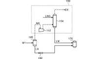
- FIG. 2 is a diagram illustrating the nitrogen adjusting section 150 according to this embodiment.
- the solid arrows indicate the flow of the gas-liquid mixture MY, the liquefied gas LA, and the liquefied gas ML.
- dashed arrows indicate the flow of the separated gas NR and the exhaust gas EX.
- the nitrogen adjustment section 150 includes a compressor 152 and a methane recovery section 154.
- the compressor 152 pressurizes the separated gas NR and guides it to the methane recovery unit 154 .
- the compressor 152 pressurizes the separated gas NR (eg, 0.25 MPaG) to 0.6 MPaG, for example.
- the separated gas NR and liquefied natural gas LNG (eg, -155°C, 0.6 MPaG) are led to the methane recovery unit 154 .
- the methane recovery unit 154 recovers methane from the post-separation gas NR.
- the methane recovery unit 154 causes the liquefied natural gas LNG and the post-separation gas NR to come into contact with each other (cleansing), thereby allowing the liquefied natural gas LNG to absorb methane contained in the post-separation gas NR.
- the methane-enriched liquefied gas LM (methane-absorbed liquefied natural gas LNG) produced in the methane recovery unit 154 is guided to a second gas-liquid separation drum 170, which will be described later.
- the methane-enriched liquefied gas LM is, for example, ⁇ 135° C. and 0.6 MPaG.
- the post-separation gas NR from which methane has been removed in the methane recovery unit 154 is discharged to the outside as the exhaust gas EX.
- the exhaust gas EX is used, for example, as fuel for a plant in which the gas cooling system 100 is provided.
- a central control unit (not shown) controls the flow rate of the compressor 152 so that the nitrogen concentration of the liquefied gas LA is within a predetermined range (for example, 0.5 mol % or more and 2 mol % or less).
- the central control section controls the pressure of the first gas-liquid separation drum 140 and also controls the flow rate of the liquefied natural gas LNG led to the methane recovery section 154 .
- the central control unit is composed of a semiconductor integrated circuit including a CPU (Central Processing Unit).
- the central control unit reads programs, parameters, etc. for operating the CPU itself from the ROM.
- the central control unit manages and controls the entire gas cooling system 100 in cooperation with RAM as a work area and other electronic circuits.
- the second decompression unit 160 decompresses the liquefied gas LA whose nitrogen concentration has been adjusted by the nitrogen adjustment unit 150 .
- the second pressure reducing section 160 is a pressure reducing valve.
- the second decompression unit 160 decompresses (flashes (evaporates and cools)) the liquefied gas LA into a gas-liquid mixture MZ of ⁇ 155° C. and 0.05 MPaG, for example.
- the second gas-liquid separation drum 170 (gas-liquid separation drum) separates the gas-liquid mixture MZ.
- the pump 180 pressurizes the liquefied natural gas LNG (liquefied gas) separated from the gas-liquid mixture MZ by the second gas-liquid separation drum 170 .
- the discharge pressure of the pump 180 is the pressure at which at least part of the liquefied natural gas LNG (liquefied gas) undergoes a phase change (vaporization) in the heat exchanger 124 .
- the discharge pressure of the pump 180 is in the range of a predetermined lower limit pressure or more and a predetermined upper limit pressure or less.
- the lower limit pressure is, for example, 1.0 MPaG.
- the upper limit pressure is, for example, 2.0 MPaG.
- pump 180 boosts liquefied natural gas LNG to 1.6 MPaG.
- a pump 180 pressurizes the liquefied natural gas LNG to shift the vaporization temperature during heat exchange in the heat exchanger 124 .
- the discharge pressure of pump 180 can be measured by a mechanical pressure gauge or a pressure gauge including a pressure receiving element.
- the pressurized liquefied natural gas LNG is shipped as a product or supplied to LNG users.
- part of the pressurized liquefied natural gas LNG is guided to the heat exchanger 124 of the cooling device 120 and then to the pre-cooling section 122, where it is used as part of the refrigerant for cooling the natural gas NG in the cooling device 120.
- Cold heat is recovered.
- the flash gas compressor 190 pressurizes the flash gas FG separated by the second gas-liquid separation drum 170 .
- flash gas compressor 190 pressurizes flash gas FG to 1.5 MPaG.
- the flash gas FG pressurized by the flash gas compressor 190 is guided to the precooling section 122 and cold heat is recovered as part of the refrigerant.
- the gas cooling system 100 uses the produced liquefied natural gas LNG as the refrigerant for cooling the natural gas NG.
- the gas cooling system 100 can partially omit a compressor dedicated to the refrigerant and a cooler as compared with the conventional dual expander process. Therefore, the gas cooling system 100 can simplify the equipment configuration and reduce the cost required for liquefaction.
- the pre-cooling section 122 of the gas cooling system 100 cools the supercritical fluid SF with a non-flammable refrigerant. Therefore, the gas cooling system 100 can inexpensively produce liquefied natural gas LNG in combination with the pre-cooling section 122 using a non-flammable refrigerant.
- natural gas NG contains trace amounts of nitrogen in addition to methane. Since the boiling point of nitrogen is lower than the boiling point of methane, the flush gas FG produced by being depressurized by the second depressurizing section 160 contains nitrogen with priority over methane. Therefore, when the nitrogen adjustment unit 150 is not provided, when the flash gas FG is returned to the booster compressor 110, the nitrogen concentration of the natural gas NG as the gas to be cooled increases ( Nitrogen is concentrated in the natural gas NG), and the amount of flash gas FG is increased. Moreover, if the nitrogen concentration of the natural gas NG increases too much, the liquefaction efficiency will decrease. Therefore, in the case where the nitrogen adjusting unit 150 is not provided, the flash gas FG must be discarded, and the problem arises that the methane contained in the flash gas FG is also discarded.
- the gas cooling system 100 includes the nitrogen adjusting section 150 that removes nitrogen from the gas-liquid mixture MY.
- the gas cooling system 100 can prevent an increase in the flash gas FG and maintain the flash gas FG at a predetermined target amount.
- the target amount is the amount of flash gas FG that, when the flash gas FG is returned to the booster compressor 110, the nitrogen concentration of the natural gas NG after being pressurized by the booster compressor 110 becomes the nitrogen concentration that is efficiently liquefied. Therefore, the gas cooling system 100 can maintain the nitrogen concentration of the natural gas NG at a concentration that allows efficient liquefaction even when the flash gas FG is returned to the booster compressor 110 (pre-cooling section 122). Therefore, the gas cooling system 100 can avoid unnecessary disposal of methane contained in the flash gas FG. Moreover, since the flash gas FG can be maintained at the target amount, the gas cooling system 100 can prevent an increase in the power of the flash gas compressor 190 .
- the nitrogen concentration of the liquefied gas LA is less than the lower limit value (for example, 0.5 mol%) of the above predetermined range, the cooling efficiency of the second pressure reducing section 160 is lowered.
- the nitrogen concentration of the liquefied gas LA exceeds the upper limit value (for example, 2 mol %) of the predetermined range, the flash gas FG exceeds the target amount.
- the nitrogen adjustment unit 150 makes the nitrogen concentration of the liquefied gas LA guided to the second pressure reduction unit 160 equal to or higher than the lower limit value.
- the gas cooling system 100 can improve the cooling efficiency by the second pressure reducing section 160 . Therefore, it is possible to lower the temperature of the liquefied natural gas LNG produced by being decompressed by the second decompression unit 160 .
- the gas cooling system 100 can lower the temperature of the liquefied natural gas LNG guided to the heat exchanger 124 by the pump 180, and can efficiently cool the supercritical fluid SF by the heat exchanger 124. Become.
- the nitrogen adjustment unit 150 makes the nitrogen concentration of the liquefied gas LA guided to the second pressure reduction unit 160 equal to or lower than the upper limit value. This enables the gas cooling system 100 to maintain the flash gas FG generated by the second gas-liquid separation drum 170 at the target amount.
- the heat exchanger 124 cools the supercritical fluid SF with the liquefied natural gas LNG. It is desirable to have as little flow of the liquefied natural gas LNG as possible in the heat exchanger 124 relative to the flow of the supercritical fluid SF. Therefore, the heat exchanger 124 utilizes the latent heat due to the phase change of the liquefied natural gas LNG to cool the supercritical fluid SF with a smaller flow rate of the liquefied natural gas LNG. In order to reduce the flow rate of the liquefied natural gas LNG, the pressure of the liquefied natural gas LNG led to the heat exchanger 124 should be reduced to lower the phase change temperature.
- the pressure of the liquefied natural gas LNG led to the heat exchanger 124 becomes too low, the pressure of the circulating natural gas CG led to the booster compressor 110 will drop and the power of the booster compressor 110 will increase. Also, if the pressure of the liquefied natural gas LNG led to the heat exchanger 124 becomes too high, the phase change temperature will rise, and the liquefied natural gas LNG will not undergo a phase change in the heat exchanger 124 .
- the discharge pressure of the pump 180 that pressurizes the liquefied natural gas LNG led to the heat exchanger 124 is set within a range of a predetermined lower limit pressure or more and a predetermined upper limit pressure or less.
- the lower limit pressure is a pressure at which the power of booster compressor 110 does not excessively increase. This allows pump 180 to prevent an excessive increase in the power of booster compressor 110 .
- the upper limit pressure is the pressure at which at least part of the liquefied natural gas LNG undergoes a phase change within the heat exchanger 124 .
- the heat exchanger 124 can cool the supercritical fluid SF with the latent heat of the liquefied natural gas LNG. Therefore, the heat exchanger 124 can cool the supercritical fluid SF with a smaller amount of liquefied natural gas LNG than the supercritical fluid SF.
- the first pressure reducing unit 130 phase-changes the supercritical fluid SF into the gas-liquid mixture MY. Therefore, the first pressure reducing unit 130 can efficiently cool the supercritical fluid SF. In addition, the first decompression unit 130 can move nitrogen to the separated gas NR. Thereby, the nitrogen adjustment unit 150 can efficiently remove nitrogen.
- the nitrogen adjustment unit 150 includes the methane recovery unit 154.
- the methane recovery unit 154 can increase the methane concentration of the liquefied natural gas LNG (liquefied gas LA).
- the nitrogen adjustment unit 150 adjusts the nitrogen concentration of the liquefied gas LA guided to the second decompression unit 160 by removing nitrogen from the gas-liquid mixture MY.
- the nitrogen adjustment unit 150 liquefies Nitrogen is added to the gas LA to optimize the nitrogen concentration of the liquefied gas LA.
- the nitrogen adjustment unit 150 adds nitrogen to the natural gas NG at the inlet of the booster compressor 110 to make the nitrogen concentration of the liquefied gas LA guided to the second pressure reducing unit 160 equal to or higher than the lower limit value and equal to or lower than the upper limit value.
- the gas cooling system 100 according to the modified example can improve the cooling efficiency of the second pressure reducing section 160 .
- the configuration in which the nitrogen adjustment unit 150 includes the methane recovery unit 154 was taken as an example.
- the nitrogen adjustment unit 150 does not have to include the methane recovery unit 154 .
- the nitrogen adjusting unit 150 should be able to adjust at least the nitrogen concentration of the liquefied gas LA obtained by being depressurized by the first depressurizing unit 130 .
- the central control unit controls the pressure of the first gas-liquid separation drum 140 by controlling the flow rate of the compressor 152 so that the nitrogen concentration of the liquefied gas LA is within a predetermined range
- the case of controlling the flow rate of the liquefied natural gas LNG led to the methane recovery unit 154 is taken as an example.
- the central control unit does not control the flow rate of the compressor 152 (does not control the pressure of the first gas-liquid separation drum 140), and the methane recovery unit 154 It is not necessary to control the flow rate of the liquefied natural gas LNG led to.
- the flow rate of compressor 152 and the flow rate of liquefied natural gas LNG led to methane recovery unit 154 are designed such that the nitrogen concentration of liquefied gas LA is 0.5 mol % or more and 2 mol % or less.
- the configuration in which the gas cooling system 100 includes the nitrogen adjustment unit 150 is taken as an example.
- the gas cooling system 100 does not have to include the nitrogen adjusting section 150 .
- the gas cooling system includes a booster compressor 110 that pressurizes a gas to be cooled, the main component of which is methane, to form a supercritical fluid SF, a precooling unit 122 that cools the supercritical fluid SF, a supercritical fluid SF, a refrigerant a heat exchanger 124 for exchanging heat with the heat exchanger 124; a second decompression unit 160, a gas-liquid separation drum (second gas-liquid separation drum 170) that separates the gas-liquid mixture obtained by decompressing the second decompression unit 160, and the gas-liquid separation drum.
- a booster compressor 110 that pressurizes a gas to be cooled, the main component of which is methane, to form a supercritical fluid SF
- a precooling unit 122 that cools the supercritical fluid SF, a
- the heat exchanger 124 cools the supercritical fluid SF using the liquefied gas pressurized by the pump 180 as a coolant, and the discharge pressure of the pump is is the pressure at which at least a portion of the liquefied gas undergoes a phase change.
- the pump 180 of the gas cooling system has a discharge pressure equal to or higher than the lower limit pressure and equal to or lower than the upper limit pressure.
- the lower limit pressure is the pressure at which the power of booster compressor 110 does not increase excessively. This allows pump 180 to prevent an excessive increase in the power of booster compressor 110 .
- the upper limit pressure is the pressure at which at least part of the liquefied natural gas LNG undergoes a phase change within the heat exchanger 124 .
- the heat exchanger 124 can cool the supercritical fluid SF with the latent heat of the liquefied natural gas LNG. Therefore, the heat exchanger 124 can cool the supercritical fluid SF with a smaller amount of liquefied natural gas LNG than the supercritical fluid SF.
- the present disclosure can efficiently liquefy renewable natural gas with low supply pressure, for example, the Sustainable Development Goals (SDGs) Goal 7 "Towards affordable, reliable, sustainable and modern energy. access to climate change” and contribute to Goal 13 “Take urgent action to combat climate change and its impacts”.
- SDGs Sustainable Development Goals
- Gas cooling system 110 Booster compressor (compressor) 120: Cooling device 122: Pre-cooling section 124: Heat exchanger 130: First decompression section 150: Nitrogen adjustment section 160: Second decompression section 170: Second gas-liquid separation drum (Gas-liquid separation drum) 180: Pump
Landscapes
- Engineering & Computer Science (AREA)
- Physics & Mathematics (AREA)
- Mechanical Engineering (AREA)
- Thermal Sciences (AREA)
- General Engineering & Computer Science (AREA)
- Chemical & Material Sciences (AREA)
- Chemical Kinetics & Catalysis (AREA)
- Oil, Petroleum & Natural Gas (AREA)
- General Chemical & Material Sciences (AREA)
- Separation By Low-Temperature Treatments (AREA)
- Filling Or Discharging Of Gas Storage Vessels (AREA)
Abstract
Description
図1は、本実施形態に係るガス冷却システム100を説明する図である。なお、図1中、実線の矢印は、流体の流れを示す。ガス冷却システム100は、メタン(CH4)を主成分とする冷却対象ガスを冷却する。本実施形態では、冷却対象ガスとして、ガス田から採取される天然ガスNGを例に挙げて説明する。天然ガスNGは、メタンおよび窒素(N2)を少なくとも含む。また、本実施形態に係るガス冷却システム100は、非可燃性冷媒のシステムである。
上記実施形態において、ガス冷却システム100が、ガス田から採取される天然ガスNG、つまり、メタンに加えて窒素を含むガスを冷却する場合を例に挙げた。このため、窒素調整部150は、気液混合物MYから窒素を除去することで、第2減圧部160に導かれる液化ガスLAの窒素濃度を調整する。
Claims (7)
- メタンを主成分とする冷却対象ガスを冷却する冷却装置と、
前記冷却装置によって冷却された前記冷却対象ガスを減圧する第1減圧部と、
前記第1減圧部によって減圧されることで得られる液化ガスの窒素濃度が所定範囲内に収まるように調整する窒素調整部と、
前記窒素調整部によって窒素濃度が調整された液化ガスを減圧する第2減圧部と、
前記第2減圧部によって減圧されることで得られる気液混合物を気液分離する気液分離ドラムと、
前記気液分離ドラムによって分離された液化ガスを昇圧するポンプと、
を備え、
前記冷却装置は、前記ポンプによって昇圧された液化ガスで前記冷却対象ガスを冷却するガス冷却システム。 - 前記冷却対象ガスを昇圧して超臨界流体とするコンプレッサを備え、
前記冷却装置は、
前記超臨界流体を冷却する予冷部と、
前記超臨界流体と、前記ポンプによって昇圧された液化ガスとを熱交換させる熱交換器と、
を有し、
前記ポンプの吐出圧は、前記熱交換器内において、前記液化ガスのうちの少なくとも一部が相変化する圧力である請求項1に記載のガス冷却システム。 - 前記第1減圧部は、前記超臨界流体を気液混合物に相変化させる請求項2に記載のガス冷却システム。
- 前記窒素調整部は、前記第1減圧部によって減圧されることで得られる前記気液混合物から窒素を除去して、前記液化ガスの窒素濃度が所定範囲内に収まるように調整する請求項3に記載のガス冷却システム。
- 前記窒素調整部は、前記第1減圧部によって減圧されることで得られる前記気液混合物を構成する分離後ガスからメタンを回収する請求項4に記載のガス冷却システム。
- 前記予冷部は、非可燃性冷媒によって前記超臨界流体を冷却する請求項2から5のいずれか1項に記載のガス冷却システム。
- メタンを主成分とする冷却対象ガスを昇圧して超臨界流体とするコンプレッサと、
前記超臨界流体を冷却する予冷部と、
前記超臨界流体と、冷媒とを熱交換させる熱交換器と、
前記熱交換器によって冷却された前記超臨界流体を減圧する第1減圧部と、
前記第1減圧部によって減圧されることで得られる液化ガスを減圧する第2減圧部と、
前記第2減圧部によって減圧されることで得られる気液混合物を気液分離する気液分離ドラムと、
前記気液分離ドラムによって分離された液化ガスを昇圧するポンプと、
を備え、
前記熱交換器は、前記ポンプによって昇圧された液化ガスを冷媒として前記超臨界流体を冷却し、
前記ポンプの吐出圧は、前記熱交換器内において、前記液化ガスのうちの少なくとも一部が相変化する圧力であるガス冷却システム。
Priority Applications (2)
| Application Number | Priority Date | Filing Date | Title |
|---|---|---|---|
| GB2316644.0A GB2621049B (en) | 2021-05-13 | 2021-06-18 | Gas cooling system |
| JP2023520742A JP7597214B2 (ja) | 2021-05-13 | 2021-06-18 | ガス冷却システム |
Applications Claiming Priority (2)
| Application Number | Priority Date | Filing Date | Title |
|---|---|---|---|
| JP2021-081870 | 2021-05-13 | ||
| JP2021081870 | 2021-05-13 |
Publications (1)
| Publication Number | Publication Date |
|---|---|
| WO2022239259A1 true WO2022239259A1 (ja) | 2022-11-17 |
Family
ID=84028107
Family Applications (1)
| Application Number | Title | Priority Date | Filing Date |
|---|---|---|---|
| PCT/JP2021/023255 Ceased WO2022239259A1 (ja) | 2021-05-13 | 2021-06-18 | ガス冷却システム |
Country Status (3)
| Country | Link |
|---|---|
| JP (1) | JP7597214B2 (ja) |
| GB (1) | GB2621049B (ja) |
| WO (1) | WO2022239259A1 (ja) |
Citations (6)
| Publication number | Priority date | Publication date | Assignee | Title |
|---|---|---|---|---|
| US20110289963A1 (en) * | 2010-04-16 | 2011-12-01 | Black & Veatch Corporation | Process for separating Nitrogen from a natural gas stream with Nitrogen stripping in the production of liquefied natural gas |
| JP2015210078A (ja) * | 2014-04-24 | 2015-11-24 | エア プロダクツ アンド ケミカルズ インコーポレイテッドAir Products And Chemicals Incorporated | 貢献する再注入回路を使用した液化天然ガスの生成における統合された窒素除去 |
| JP2015210077A (ja) * | 2014-04-24 | 2015-11-24 | エア プロダクツ アンド ケミカルズ インコーポレイテッドAir Products And Chemicals Incorporated | 中間供給ガス分離を使用した液化された天然ガスの生産における統合された窒素除去 |
| JP2016169837A (ja) * | 2015-03-13 | 2016-09-23 | 三井造船株式会社 | ボイルオフガス回収システム |
| JP2020507736A (ja) * | 2017-02-13 | 2020-03-12 | エクソンモービル アップストリーム リサーチ カンパニー | 高圧圧縮及び膨張による天然ガスの予冷 |
| JP2020535378A (ja) * | 2017-09-29 | 2020-12-03 | エクソンモービル アップストリーム リサーチ カンパニー | 高圧膨張プロセスによる天然ガス液化 |
Family Cites Families (2)
| Publication number | Priority date | Publication date | Assignee | Title |
|---|---|---|---|---|
| JPS58183901A (ja) * | 1982-04-14 | 1983-10-27 | コステイン・ペトロカ−ボン・リミテッド | 分縮による混合ガス分離法 |
| US8522574B2 (en) * | 2008-12-31 | 2013-09-03 | Kellogg Brown & Root Llc | Method for nitrogen rejection and or helium recovery in an LNG liquefaction plant |
-
2021
- 2021-06-18 GB GB2316644.0A patent/GB2621049B/en active Active
- 2021-06-18 JP JP2023520742A patent/JP7597214B2/ja active Active
- 2021-06-18 WO PCT/JP2021/023255 patent/WO2022239259A1/ja not_active Ceased
Patent Citations (6)
| Publication number | Priority date | Publication date | Assignee | Title |
|---|---|---|---|---|
| US20110289963A1 (en) * | 2010-04-16 | 2011-12-01 | Black & Veatch Corporation | Process for separating Nitrogen from a natural gas stream with Nitrogen stripping in the production of liquefied natural gas |
| JP2015210078A (ja) * | 2014-04-24 | 2015-11-24 | エア プロダクツ アンド ケミカルズ インコーポレイテッドAir Products And Chemicals Incorporated | 貢献する再注入回路を使用した液化天然ガスの生成における統合された窒素除去 |
| JP2015210077A (ja) * | 2014-04-24 | 2015-11-24 | エア プロダクツ アンド ケミカルズ インコーポレイテッドAir Products And Chemicals Incorporated | 中間供給ガス分離を使用した液化された天然ガスの生産における統合された窒素除去 |
| JP2016169837A (ja) * | 2015-03-13 | 2016-09-23 | 三井造船株式会社 | ボイルオフガス回収システム |
| JP2020507736A (ja) * | 2017-02-13 | 2020-03-12 | エクソンモービル アップストリーム リサーチ カンパニー | 高圧圧縮及び膨張による天然ガスの予冷 |
| JP2020535378A (ja) * | 2017-09-29 | 2020-12-03 | エクソンモービル アップストリーム リサーチ カンパニー | 高圧膨張プロセスによる天然ガス液化 |
Also Published As
| Publication number | Publication date |
|---|---|
| JP7597214B2 (ja) | 2024-12-10 |
| GB2621049B (en) | 2024-12-18 |
| GB2621049A (en) | 2024-01-31 |
| JPWO2022239259A1 (ja) | 2022-11-17 |
| GB202316644D0 (en) | 2023-12-13 |
Similar Documents
| Publication | Publication Date | Title |
|---|---|---|
| JP5139292B2 (ja) | Lngのための天然ガス液化方法 | |
| JP5984192B2 (ja) | 天然ガスの液化プロセス | |
| JP5231002B2 (ja) | 蒸気圧縮装置およびそれに関連する遷臨界サイクルを実施する方法 | |
| TWI424870B (zh) | 用於液化來自燃燒裝置之煙道氣的方法及裝置 | |
| KR101894076B1 (ko) | 천연가스의 액화 시스템 및 액화 방법 | |
| EP3368631B1 (en) | Method using hydrogen-neon mixture refrigeration cycle for large-scale hydrogen cooling and liquefaction | |
| RU2009144777A (ru) | Способ сжижения природного газа | |
| JP2013242138A (ja) | 液化方法及び液化装置 | |
| CA2813260A1 (en) | A method to produce lng | |
| JP2016128738A (ja) | ガス液化装置及びガス液化方法 | |
| CN107683397B (zh) | 工业气体和烃类气体的液化 | |
| CN104807288A (zh) | 高压天然气的凝液回收方法 | |
| EA011605B1 (ru) | Способ обработки потока спг, полученного охлаждением при помощи первого цикла охлаждения, и установка для его осуществления | |
| RU2698565C2 (ru) | Способ сжижения природного газа | |
| JP5638059B2 (ja) | 冷媒によってメタンから冷熱を回収する冷凍方法およびシステム | |
| CN101228405B (zh) | 生产lng的天然气液化方法 | |
| JP7597214B2 (ja) | ガス冷却システム | |
| US20230375261A1 (en) | Closed loop lng process for a feed gas with nitrogen | |
| KR20230171430A (ko) | 수소 또는 헬륨 액화 처리에서 사전냉각을 위한 시스템 및 방법 | |
| KR20200021718A (ko) | 천연 가스 액화 처리 장치 | |
| US10571187B2 (en) | Temperature controlled method to liquefy gas and a production plant using the method | |
| WO2003071199A1 (en) | Refrigerating method and refrigerating system utilizing gas hydrate | |
| RU2775341C1 (ru) | Способ сжижения природного газа (варианты) | |
| EP4571224A1 (en) | A method for co2 compression and liquefaction | |
| JP4879606B2 (ja) | 冷熱供給システム |
Legal Events
| Date | Code | Title | Description |
|---|---|---|---|
| 121 | Ep: the epo has been informed by wipo that ep was designated in this application |
Ref document number: 21941988 Country of ref document: EP Kind code of ref document: A1 |
|
| WWE | Wipo information: entry into national phase |
Ref document number: 2023520742 Country of ref document: JP |
|
| ENP | Entry into the national phase |
Ref document number: 202316644 Country of ref document: GB Kind code of ref document: A Free format text: PCT FILING DATE = 20210618 |
|
| WWE | Wipo information: entry into national phase |
Ref document number: 2316644.0 Country of ref document: GB |
|
| NENP | Non-entry into the national phase |
Ref country code: DE |
|
| WWP | Wipo information: published in national office |
Ref document number: 2316644.0 Country of ref document: GB |
|
| 122 | Ep: pct application non-entry in european phase |
Ref document number: 21941988 Country of ref document: EP Kind code of ref document: A1 |
|
| WWG | Wipo information: grant in national office |
Ref document number: 2316644.0 Country of ref document: GB |