WO2022230724A1 - Porte-outil anti-vibrations et son procédé de fabrication - Google Patents
Porte-outil anti-vibrations et son procédé de fabrication Download PDFInfo
- Publication number
- WO2022230724A1 WO2022230724A1 PCT/JP2022/018191 JP2022018191W WO2022230724A1 WO 2022230724 A1 WO2022230724 A1 WO 2022230724A1 JP 2022018191 W JP2022018191 W JP 2022018191W WO 2022230724 A1 WO2022230724 A1 WO 2022230724A1
- Authority
- WO
- WIPO (PCT)
- Prior art keywords
- vibration
- base material
- tool holder
- axis
- metal
- Prior art date
Links
- 238000004519 manufacturing process Methods 0.000 title claims description 45
- 238000000034 method Methods 0.000 title claims description 28
- 239000000463 material Substances 0.000 claims abstract description 227
- 229910052751 metal Inorganic materials 0.000 claims abstract description 65
- 239000002184 metal Substances 0.000 claims abstract description 65
- 229910000765 intermetallic Inorganic materials 0.000 claims abstract description 32
- 239000000758 substrate Substances 0.000 claims abstract description 19
- 150000001875 compounds Chemical class 0.000 claims abstract description 8
- 238000013016 damping Methods 0.000 claims description 91
- 238000002844 melting Methods 0.000 claims description 25
- 230000008018 melting Effects 0.000 claims description 24
- 229910000831 Steel Inorganic materials 0.000 claims description 19
- 239000010959 steel Substances 0.000 claims description 19
- 239000000654 additive Substances 0.000 claims description 17
- 230000000996 additive effect Effects 0.000 claims description 17
- VNTLIPZTSJSULJ-UHFFFAOYSA-N chromium molybdenum Chemical compound [Cr].[Mo] VNTLIPZTSJSULJ-UHFFFAOYSA-N 0.000 claims description 10
- OGSYQYXYGXIQFH-UHFFFAOYSA-N chromium molybdenum nickel Chemical compound [Cr].[Ni].[Mo] OGSYQYXYGXIQFH-UHFFFAOYSA-N 0.000 claims description 9
- 229910000975 Carbon steel Inorganic materials 0.000 claims description 7
- 239000010962 carbon steel Substances 0.000 claims description 7
- 238000005266 casting Methods 0.000 claims description 7
- 239000010935 stainless steel Substances 0.000 claims description 6
- 229910001220 stainless steel Inorganic materials 0.000 claims description 6
- 229910000838 Al alloy Inorganic materials 0.000 claims description 5
- 238000002955 isolation Methods 0.000 claims description 5
- 229910001315 Tool steel Inorganic materials 0.000 claims description 4
- 229910000881 Cu alloy Inorganic materials 0.000 claims description 3
- 229910000861 Mg alloy Inorganic materials 0.000 claims description 2
- 229910045601 alloy Inorganic materials 0.000 claims description 2
- 239000000956 alloy Substances 0.000 claims description 2
- 150000001247 metal acetylides Chemical class 0.000 claims description 2
- 150000002739 metals Chemical class 0.000 abstract 1
- 239000002994 raw material Substances 0.000 description 32
- 239000000843 powder Substances 0.000 description 16
- 238000001816 cooling Methods 0.000 description 12
- 230000004048 modification Effects 0.000 description 11
- 238000012986 modification Methods 0.000 description 11
- 230000002093 peripheral effect Effects 0.000 description 8
- 230000000052 comparative effect Effects 0.000 description 6
- 230000007423 decrease Effects 0.000 description 6
- 238000010586 diagram Methods 0.000 description 6
- 238000007493 shaping process Methods 0.000 description 6
- 239000006096 absorbing agent Substances 0.000 description 5
- IJGRMHOSHXDMSA-UHFFFAOYSA-N Atomic nitrogen Chemical compound N#N IJGRMHOSHXDMSA-UHFFFAOYSA-N 0.000 description 4
- 238000003754 machining Methods 0.000 description 4
- 238000000465 moulding Methods 0.000 description 4
- CURLTUGMZLYLDI-UHFFFAOYSA-N Carbon dioxide Chemical compound O=C=O CURLTUGMZLYLDI-UHFFFAOYSA-N 0.000 description 3
- 230000000694 effects Effects 0.000 description 3
- 239000007788 liquid Substances 0.000 description 3
- 238000003801 milling Methods 0.000 description 3
- 239000011651 chromium Substances 0.000 description 2
- 238000010894 electron beam technology Methods 0.000 description 2
- 239000007789 gas Substances 0.000 description 2
- 230000001678 irradiating effect Effects 0.000 description 2
- 239000011777 magnesium Substances 0.000 description 2
- 239000000203 mixture Substances 0.000 description 2
- 229910052757 nitrogen Inorganic materials 0.000 description 2
- VYZAMTAEIAYCRO-UHFFFAOYSA-N Chromium Chemical compound [Cr] VYZAMTAEIAYCRO-UHFFFAOYSA-N 0.000 description 1
- XEEYBQQBJWHFJM-UHFFFAOYSA-N Iron Chemical compound [Fe] XEEYBQQBJWHFJM-UHFFFAOYSA-N 0.000 description 1
- FYYHWMGAXLPEAU-UHFFFAOYSA-N Magnesium Chemical compound [Mg] FYYHWMGAXLPEAU-UHFFFAOYSA-N 0.000 description 1
- 230000004308 accommodation Effects 0.000 description 1
- 229910052782 aluminium Inorganic materials 0.000 description 1
- XAGFODPZIPBFFR-UHFFFAOYSA-N aluminium Chemical compound [Al] XAGFODPZIPBFFR-UHFFFAOYSA-N 0.000 description 1
- 230000005540 biological transmission Effects 0.000 description 1
- 229910002092 carbon dioxide Inorganic materials 0.000 description 1
- 239000001569 carbon dioxide Substances 0.000 description 1
- 235000011089 carbon dioxide Nutrition 0.000 description 1
- 229910052804 chromium Inorganic materials 0.000 description 1
- 230000008021 deposition Effects 0.000 description 1
- 230000004927 fusion Effects 0.000 description 1
- 238000010030 laminating Methods 0.000 description 1
- 229910052749 magnesium Inorganic materials 0.000 description 1
- 239000000155 melt Substances 0.000 description 1
- 239000007769 metal material Substances 0.000 description 1
- 238000009751 slip forming Methods 0.000 description 1
Images


Classifications
-
- B—PERFORMING OPERATIONS; TRANSPORTING
- B23—MACHINE TOOLS; METAL-WORKING NOT OTHERWISE PROVIDED FOR
- B23B—TURNING; BORING
- B23B27/00—Tools for turning or boring machines; Tools of a similar kind in general; Accessories therefor
-
- B—PERFORMING OPERATIONS; TRANSPORTING
- B23—MACHINE TOOLS; METAL-WORKING NOT OTHERWISE PROVIDED FOR
- B23B—TURNING; BORING
- B23B29/00—Holders for non-rotary cutting tools; Boring bars or boring heads; Accessories for tool holders
-
- B—PERFORMING OPERATIONS; TRANSPORTING
- B23—MACHINE TOOLS; METAL-WORKING NOT OTHERWISE PROVIDED FOR
- B23C—MILLING
- B23C9/00—Details or accessories so far as specially adapted to milling machines or cutter
-
- B—PERFORMING OPERATIONS; TRANSPORTING
- B23—MACHINE TOOLS; METAL-WORKING NOT OTHERWISE PROVIDED FOR
- B23Q—DETAILS, COMPONENTS, OR ACCESSORIES FOR MACHINE TOOLS, e.g. ARRANGEMENTS FOR COPYING OR CONTROLLING; MACHINE TOOLS IN GENERAL CHARACTERISED BY THE CONSTRUCTION OF PARTICULAR DETAILS OR COMPONENTS; COMBINATIONS OR ASSOCIATIONS OF METAL-WORKING MACHINES, NOT DIRECTED TO A PARTICULAR RESULT
- B23Q11/00—Accessories fitted to machine tools for keeping tools or parts of the machine in good working condition or for cooling work; Safety devices specially combined with or arranged in, or specially adapted for use in connection with, machine tools
-
- B—PERFORMING OPERATIONS; TRANSPORTING
- B23—MACHINE TOOLS; METAL-WORKING NOT OTHERWISE PROVIDED FOR
- B23Q—DETAILS, COMPONENTS, OR ACCESSORIES FOR MACHINE TOOLS, e.g. ARRANGEMENTS FOR COPYING OR CONTROLLING; MACHINE TOOLS IN GENERAL CHARACTERISED BY THE CONSTRUCTION OF PARTICULAR DETAILS OR COMPONENTS; COMBINATIONS OR ASSOCIATIONS OF METAL-WORKING MACHINES, NOT DIRECTED TO A PARTICULAR RESULT
- B23Q3/00—Devices holding, supporting, or positioning work or tools, of a kind normally removable from the machine
- B23Q3/12—Devices holding, supporting, or positioning work or tools, of a kind normally removable from the machine for securing to a spindle in general
Definitions
- the present invention relates to an anti-vibration tool holder and a manufacturing method thereof.
- anti-vibration tool holders that are detachably attached to the spindle of processing machines such as machining centers and hold tools are known.
- Patent Document 1 discloses an anti-vibration tool holder with a built-in dynamic absorber for suppressing chatter vibration.
- the dynamic absorber has a vibrating body, a cylindrical vibration damping body surrounding the vibrating body, a support supporting one end of the vibration pair, and a restricting member restricting the rotation of the support about the axis.
- each member that constitutes the dynamic absorber is configured separately from each other and further from other members that configure the tool body. Therefore, in the anti-vibration tool holder described in Patent Document 1, the connection relationship between the dynamic absorber and other members (for example, the base material) is complicated, and it is difficult to suppress the decrease in rigidity that accompanies the provision of the dynamic absorber. ,Have difficulty.
- a main object of the present disclosure is to provide a vibration-isolating tool holder that is equipped with a vibration damping body while suppressing a decrease in rigidity caused by the provision of the vibration damping body.
- the anti-vibration tool holder according to the present disclosure is an anti-vibration tool holder that has an axis and is rotated about the axis by a spindle of a processing machine.
- a vibration isolation tool holder according to the present disclosure includes a base material including a shank part attached to a spindle and an arbor part for gripping a tool, and at least one of the shank part and/or the arbor part disposed inside the base material. and a vibration damper.
- a material that constitutes the base includes a first metal.
- a material that constitutes the at least one vibration damper includes a second metal that is different from the first metal.
- An intermetallic compound layer containing a compound of a first metal and a second metal is formed at the interface between the substrate and the at least one vibration damper.
- a method for manufacturing an anti-vibration tool holder according to the present disclosure is a method for manufacturing an anti-vibration tool holder that is rotated about an axis by a spindle of a processing machine.
- a method of manufacturing an anti-vibration tool holder according to the present disclosure comprises forming by metal additive manufacturing an anti-vibration tool holder comprising a substrate and at least one vibration damping body disposed within the substrate. .
- the forming step includes a first step of melting and solidifying a material forming the base material by metal additive manufacturing, and a second step of melting and solidifying a material forming at least one vibration damper by metal additive manufacturing. 2 steps.
- an anti-vibration tool holder that is equipped with a vibration damping body and that suppresses a decrease in rigidity due to the provision of the vibration damping body.
- FIG. 2 is a perspective view showing the anti-vibration tool holder according to Embodiment 1;
- Figure 2 is a side view of the anti-vibration tool holder shown in Figure 1;
- FIG. 3 is a cross-sectional view seen from arrows III-III in FIG. 2;
- 4 is a cross-sectional view as seen from arrow IV-IV in FIG. 3;
- FIG. 5 is a partially enlarged cross-sectional view for explaining an interface between a base material and a vibration damper of the anti-vibration tool holder shown in FIGS. 1 to 4;
- 4 is a flow chart showing an example of a method for manufacturing the anti-vibration tool holder according to Embodiment 1.
- FIG. FIG. 1 is a side view of the anti-vibration tool holder shown in Figure 1;
- FIG. 3 is a cross-sectional view seen from arrows III-III in FIG. 2;
- 4 is a cross-sectional view as seen from arrow IV-
- FIG. 5 is a diagram for explaining an example of a layered manufacturing process of the method for manufacturing the anti-vibration tool holder according to Embodiment 1;
- FIG. 8 is a diagram for explaining another example of the layered manufacturing process of the method for manufacturing the anti-vibration tool holder according to Embodiment 1;
- FIG. 9 is a diagram for explaining a first step in another example of the layered manufacturing process shown in FIG. 8; 9. It is a figure for demonstrating the 2nd process after the 1st process shown by FIG. 9 in another example of the layered manufacturing process shown by FIG.
- FIG. 4 is a cross-sectional view for explaining a usage example of the anti-vibration tool holder according to Embodiment 1;
- FIG. 11 is a partially enlarged cross-sectional view for explaining an interface between a base material and a vibration damper of the anti-vibration tool holder according to Embodiment 2;
- FIG. 8 is a diagram for explaining a modification of the method for manufacturing the anti-vibration tool holder according to Embodiment 1 or Embodiment 2;
- FIG. 5 is a cross-sectional view showing a first modification of the anti-vibration tool holder according to Embodiment 1 or Embodiment 2;
- FIG. 5 is a cross-sectional view showing a second modification of the anti-vibration tool holder according to Embodiment 1 or Embodiment 2;
- FIG. 8 is a cross-sectional view showing a third modification of the anti-vibration tool holder according to Embodiment 1 or Embodiment 2;
- FIG. 11 is a cross-sectional view showing a fourth modification of the anti-vibration tool holder according to Embodiment 1 or Embodiment 2;
- FIG. 11 is a cross-sectional view showing a fifth modification of the anti-vibration tool holder according to Embodiment 1 or Embodiment 2;
- FIG. 11 is a cross-sectional view showing a sixth modification of the anti-vibration tool holder according to Embodiment 1 or Embodiment 2;
- FIG. 11 is a cross-sectional view showing a seventh modification of the anti-vibration tool holder according to Embodiment 1 or Embodiment 2;
- FIG. 12 is a flow chart for explaining a process of casting a vibration-isolating tool holder as an example of a method for manufacturing a vibration-isolating tool holder according to a seventh modified example;
- FIG. 11 is a partially enlarged cross-sectional view for explaining the interface between the base material and the vibration damping body of the anti-vibration tool holder according to Embodiment 3;
- FIG. 11 is a partially enlarged cross-sectional view for explaining an interface between a base material and a vibration damping body in a modification of the anti-vibration tool holder according to Embodiment 3;
- the anti-vibration tool holder 10 according to Embodiment 1 shown in FIGS. 1 to 4 is a tool holder that is attached to the spindle of a processing machine such as a milling cutter or an end mill and that holds a tool.
- the anti-vibration tool holder 10 has an axis C (see FIGS. 1-4) and is rotated about the axis C by the spindle.
- the axis C of the anti-vibration tool holder is parallel to each of the spindle axis and the tool axis.
- the axis C of the anti-vibration tool holder When viewed from the extending direction of the axis C of the anti-vibration tool holder, the axis C of the anti-vibration tool holder is arranged so as to overlap, for example, the axis of the spindle and the axis of the tool.
- the axis C of the anti-vibration tool holder is, for example, arranged coaxially with each of the axis of the spindle and the axis of the tool.
- the anti-vibration tool holder 10 mainly includes a base material 11. As shown in FIGS.
- the base material 11 is constructed as a single member.
- the base material 11 includes a shank portion 1 attached to the spindle of the processing machine and an arbor portion 2 for gripping the tool.
- part of the base material 11 forms the shank part 1 attached to the spindle of the processing machine
- the other part of the base material 11 forms the arbor part 2 for gripping the tool.
- the arbor portion 2 is arranged side by side with the shank portion 1 in the direction in which the axis C extends.
- the shank part 1 is detachable from the main shaft.
- the shank portion 1 includes, for example, an inclined portion 1A and a flange portion 1B.
- the inclined portion 1A has an inclined surface that is inclined such that the length (creeping distance) in the circumferential direction with respect to the axis C decreases as the distance from the arbor portion 2 increases in the direction in which the axis C extends.
- the inclined surface is provided so as to be in contact with the main shaft of the processing machine.
- the flange portion 1B is arranged between the inclined portion 1A and the arbor portion 2 in the extending direction of the axis C, and protrudes outward from the inclined portion 1A in the radial direction with respect to the axis C. As shown in FIG.
- the inclined portion 1A is arranged in parallel with the main shaft at least in the radial direction with respect to the axis C, and the flange portion 1B is arranged in parallel with the main shaft in at least the direction in which the axis extends.
- the base material 11 has a housing portion 3 that houses a part of the tool.
- the accommodating portion 3 opens at one end of the base material 11 in the extending direction of the axis C.
- the accommodating portion 3 is provided so that the axis of the tool accommodated in the accommodating portion 3 is coaxial with the axis C of the anti-vibration tool holder 10 .
- the arbor portion 2 is provided in a tubular shape so as to surround the accommodating portion 3 in the radial direction with respect to the axis C. As shown in FIG.
- the arbor portion 2 is provided in a cylindrical shape around the axis C, for example.
- the base material 11 has a contact surface that contacts the main shaft at the shank portion 1 .
- the contact surface that comes into contact with the spindle is composed of the base material 11 .
- the base material 11 has a contact surface that contacts the tool in the arbor portion 2 .
- the contact surface that comes into contact with the tool is composed of the base material 11 . From a different point of view, each of the plurality of vibration dampers 12 is not exposed on the contact surface that contacts the spindle or the tool.
- a through hole 4 is further formed in the base material 11, for example, so as to be continuous with the housing portion 3 in the extending direction of the axis.
- the anti-vibration tool holder 10 further comprises a plurality of vibration dampers 12.
- Each of the plurality of vibration dampers 12 is arranged inside the base material 11 .
- the plurality of vibration dampers 12 include, for example, vibration dampers 12 arranged inside the shank portion 1 and vibration dampers 12 arranged inside the arbor portion 2 .
- Each of the plurality of vibration dampers 12 is configured as a separate member from each other.
- Each of the plurality of vibration dampers 12 is configured as a separate member from the base material 11 .
- Each of the plurality of vibration dampers 12 is embedded inside the base material 11 .
- the plurality of vibration dampers 12 include, for example, a first vibration damper 5, a second vibration damper 6, a third vibration damper 7, a fourth vibration damper 8, and a fifth vibration damper 9.
- the first vibration damper 5 , the second vibration damper 6 and the third vibration damper 7 are arranged inside the arbor section 2 .
- the fourth vibration damper 8 and the fifth vibration damper 9 are arranged inside the shank portion 1 .
- each of the plurality of vibration dampers 12 is arranged so as to surround the axis C.
- the second vibration damping body 6 is arranged so as to surround the axis C.
- the second vibration damping body 6 is an annular member.
- each of the first vibration damping body 5, the third vibration damping body 7, the fourth vibration damping body 8, and the fifth vibration damping body 9 is also an annular member.
- Each of the plurality of vibration dampers 12 is arranged such that the central axis of each of the plurality of vibration dampers 12 overlaps the axis C of the anti-vibration tool holder 10 .
- the first vibration damping body 5 and the second vibration damping body 6 are arranged side by side with a space therebetween in the extending direction of the axis C.
- the second vibration damper 6 is arranged on the shank portion 1 side with respect to the first vibration damper 5 in the extending direction of the axis C.
- All of the first vibration damping body 5 and part of the second vibration damping body 6 in the extending direction of the axis C are spaced apart from the housing portion 3 in the radial direction with respect to the axis C, and more than the housing portion 3. placed outside. All of the first vibration damping body 5 and a part of the second vibration damping body 6 in the extending direction of the axis C surround the housing portion 3 .
- the remainder of the second vibration damping body 6 in the extending direction of the axis C is spaced apart from the third vibration damping body 7 in the radial direction with respect to the axis C and is arranged outside the third vibration damping body 7. .
- the remainder of the second vibration damper 6 in the direction of extension of the axis C surrounds the third vibration damper 7 .
- the third vibration damping body 7 is spaced apart from the accommodating portion 3 in the extending direction of the axis C, and is arranged on the shank portion 1 side with respect to the accommodating portion 3 .
- the third vibration damping body 7 is arranged radially with respect to the axis C at a distance from the through hole 4 and outside the through hole 4 .
- the fourth vibration damping body 8 is arranged inside the inclined portion 1A.
- the fourth vibration damping body 8 is arranged along the inclined surface of the inclined portion 1A.
- the fourth vibration damper 8 is spaced apart from each of the housing portion 3 and the second vibration damper 6 in the direction in which the axis C extends.
- the fifth vibration damping body 9 is arranged inside the flange portion 1B.
- the fifth vibration damper 9 is arranged between the second vibration damper 6 and the fourth vibration damper 8 in the extending direction of the axis C. As shown in FIG.
- the fifth vibration damper 9 is arranged outside the fourth vibration damper 8 in the radial direction with respect to the axis C. As shown in FIG.
- the material constituting the base material 11 contains the first metal.
- the first metal is any metal element contained in the material forming the base material 11 .
- the rigidity of the material forming the base material 11 is higher than the rigidity of the material forming each of the plurality of vibration dampers 12 .
- the material constituting the base material 11 includes, for example, at least one selected from the first group consisting of carbon steel, chromium molybdenum steel, nickel chromium molybdenum steel, stainless steel, and cemented carbide.
- Chromium-molybdenum steel and nickel-chromium-molybdenum steel may be any chromium-molybdenum steel and nickel-chromium-molybdenum steel specified in the JIS standard (JIS G 4053:2016).
- An example of a chromium molybdenum steel is SCM435.
- the first metal is iron (Fe) or chromium (Cr), for example.
- the material forming each of the plurality of vibration dampers 12 includes a second metal different from the first metal.
- the second metal is an arbitrary metal element contained in the material forming each of the plurality of vibration dampers 12 .
- the material forming each of the plurality of vibration dampers 12 includes at least one selected from the second group consisting of, for example, magnesium alloys, aluminum alloys, and cemented carbides.
- the second metal is magnesium (Mg) or aluminum (Al), for example.
- an intermetallic compound layer 13 is formed at the interface between the base material 11 and each of the plurality of vibration dampers 12 .
- Intermetallic compound layer 13 contains a compound of a first metal and a second metal.
- each of the plurality of vibration dampers 12 is metallically bonded to the base material 11 .
- the intermetallic compound layer 13 is formed over the entire interface between the base material 11 and each of the plurality of vibration dampers 12 . In other words, the intermetallic compound layer 13 is formed on the entire surface of each of the plurality of vibration dampers 12 .
- the thickness of the intermetallic compound layer 13 is thinner than the minimum width of each of the plurality of vibration dampers 12 (for example, the width in the radial direction with respect to the axis C for the second metal).
- the thickness of the intermetallic compound layer 13 is, for example, 1 ⁇ m or more and 1 mm or less.
- the method for manufacturing the anti-vibration tool holder 10 includes a step of forming the anti-vibration tool holder 10 including the base material 11 and each of the plurality of vibration damping bodies 12 by the metal additive manufacturing method (S1). and a step ( S ⁇ b>2 ) of shaping the anti-vibration tool holder 10 .
- the metal additive manufacturing method is an additive manufacturing method using metal materials.
- the additive manufacturing method is, for example, directed energy deposition (DED) or powder bed fusion (PBF).
- DED directed energy deposition
- PPF powder bed fusion
- step (S1) shape data representing the shape of the anti-vibration tool holder 10 is first divided into a plurality of layers laminated in the extending direction of the axis C, thereby preparing shape data for each of the plurality of layers.
- the shape data indicating the shape of the anti-vibration tool holder 10 may be divided into a plurality of layers stacked in a direction different from the direction in which the axis C extends.
- a plurality of layered objects are continuously formed based on the shape data of each of the plurality of layers.
- Each of the plurality of layered shaped articles includes at least one of a shaped article of a material forming the base material 11 and a shaped article of a material forming each of the plurality of vibration dampers 12 .
- the anti-vibration tool holder 10 is formed by integrally laminating a plurality of layered objects.
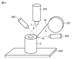
- FIG. 7 is a diagram for explaining the step (S1) when the DED method is adopted as the metal additive manufacturing method.
- the DED method includes a base plate 200, a supply unit 201 for supplying a modeling material M to a region R to be shaped on the base plate 200, and a light source 202 for irradiating the region R with a high-energy electron beam or laser L.
- An additive manufacturing device is used.
- the position of the supply unit 201 and the light source 202 relative to the base plate 200 can be changed.
- the supply unit 201 includes a first supply unit that supplies raw materials for molding the base material 11 and a second supply unit that supplies raw materials for molding each of the plurality of vibration damping bodies 12 .
- the supply unit 201 is provided so as to supply each wire-shaped raw material to the region R, for example.
- the supply unit 201 may be provided so as to supply each powdery raw material to the region R.
- the supply unit 201 supplies the raw material M for shaping the base material 11 to the area R where the base material 11 is to be shaped, while the light source 202 is turned on to the area R. is irradiated with the laser L.
- the energy of the laser L is set so as to melt the raw material M for modeling the base material 11 .
- the supply part 201 and the light source 202 are scanned relative to the base plate 200 so that the region R moves continuously within the same layer.
- a light source 202 irradiates a laser L onto a region where each of the plurality of vibration damping bodies 12 is to be formed, while the supply unit 201 supplies raw materials for forming each of the plurality of vibration damping bodies 12. .
- the energy of the laser L is set so as to melt the raw material for forming each of the plurality of vibration damping bodies 12 .
- each layered product is obtained by solidifying after each raw material supplied to each region is melted.
- the supply unit 201 and the light source 202 are moved relative to the base plate 200 by the thickness of the layered structure for one layer.
- the above scanning is repeated again. If there is another layered object that has been previously formed directly under the layered object, the raw material supplied to the region R and part of the layered object located directly under the region R are melted and then solidified. do.
- a three-dimensional object O is obtained in which a plurality of layered objects are three-dimensionally laminated.
- the intermetallic compound layer 13 is formed at the interface between the base material 11 and each of the plurality of vibration dampers 12 in each layered article or between a plurality of layered articles adjacent in the stacking direction. be done.
- FIGS. 8 to 10 are diagrams for explaining the step (S1) when the PBF method is adopted as the metal additive manufacturing method.
- a base plate 300 in the PBF method, a base plate 300, a supply unit 301 for forming a powder bed PB by laying a layer of the material M for modeling on the base plate 300, and a modeling part of the powder bed PB
- a layered manufacturing apparatus is used that includes a light source 302 for irradiating a high-energy electron beam or laser L onto a region to be formed, and a drive unit 303 for moving the base plate 300 relative to the supply unit 301 .
- the supply section 301 includes a powder hopper 301A, a modeling stage 301B, and a squeeze 301C.
- the modeling stage 301B has a tubular portion extending in the vertical direction and a flange portion extending outward from the upper end portion of the tubular portion.
- the base plate 300 and the driving portion 303 are provided so as to move vertically inside the cylindrical portion.
- the powder hopper 301A supplies the powdery raw material M onto the base plate 300 and the modeling stage 301B.
- the powder hopper 301A includes a first powder hopper that supplies raw materials for shaping the base material 11 and a second powder hopper that supplies raw materials for shaping each of the plurality of vibration dampers 12 .
- the squeeze 301C flattens the powdered raw material supplied onto the base plate 300 and the modeling stage 301B by the powder hopper 301A.
- a powder bed PB is formed on the base plate 300 by the feeder 301 .
- the light source 302 irradiates the laser L on the area where the substrate 11 is to be modeled in the powder bed PB made of raw materials for modeling the substrate 11, based on the shape data of each layer. Furthermore, the light source 302 is scanned relative to the base plate 300 so that the regions are continuously moved within the same layer. As a result, a layered article for one layer of the substrate 11 is formed. Next, the base plate 300 moves upward relative to the modeling stage 301B by the thickness of the layered article for one layer. As a result, the layered product for one layer of the base material 11 and the region where the vibration damping body 12 is to be formed are arranged on the upper surface of the powder bed PB made of the raw material for forming the base material 11 .
- the supply unit 301 forms a powder bed made of raw material for molding the vibration damping body 12 on the upper surface of the powder bed PB made of raw material for molding the base material 11 .
- the light source 302 irradiates the laser L onto the region where the vibration damping body 12 is to be formed in the powder bed made of raw materials for forming each vibration damping body 12 .
- the light source 302 is scanned relative to the base plate 300 so that the region moves continuously within the same layer.
- the layered article for one layer of each vibration damping body 12 is formed so as to form a single layered article together with the layered article of the base material 11 .
- the base plate 300 is moved downward relative to the modeling stage 301B by the thickness of the layered article for one layer. After that, the above scanning is repeated again.
- the intermetallic compound layer 13 is formed at the interface between the base material 11 and each of the plurality of vibration dampers 12 in each layered article or between a plurality of layered articles adjacent in the stacking direction. be done.
- the step (S2) of shaping the anti-vibration tool holder 10 is performed.
- the shaping step (S2) may be performed as necessary, and may not be performed.
- an intermetallic compound layer 13 is formed on the interface between the base material 11 and each of the plurality of vibration dampers 12 . That is, each of the plurality of vibration dampers 12 is metallically bonded to the base material 11 . In the anti-vibration tool holder 10, each of the plurality of vibration dampers 12 is metallically bonded to the base material 11.
- a vibration damping tool holder in which the vibration dampers are not metallically bonded to the base material (hereinafter referred to as a comparative anti-vibration tool holder) As compared with a vibration tool holder), a decrease in rigidity due to the provision of a plurality of vibration dampers 12 is suppressed. Furthermore, in the anti-vibration tool holder 10, chatter vibrations during machining can be damped by the plurality of vibration dampers 12, so a decrease in machining accuracy is suppressed.
- the rigidity is improved as described above without increasing the weight. Therefore, in the anti-vibration tool holder 10, the weight can be reduced without lowering the rigidity as compared with the anti-vibration tool holder of the comparative example.
- the anti-vibration tool holder 10 has more vibration dampers than the anti-vibration tool holder of the comparative example.
- the wear and tear of each of the 12 can be suppressed.
- the anti-vibration tool holder of the comparative example when chatter vibration occurs, the base material and the vibration damping body vibrate in different modes as different members, so the vibration damping body is easily worn.
- the anti-vibration tool holder 10 when chatter vibration occurs, the base material 11 and each of the plurality of vibration dampers 12 can vibrate together. , the vibration damper is less likely to wear out.
- each of the plurality of vibration dampers 12 is embedded inside the base material 11, and the intermetallic compound layer 13 covers the entire surface of each of the plurality of vibration dampers 12. formed. Therefore, in the anti-vibration tool holder 10 , each of the plurality of vibration dampers 12 is less likely to be worn than when at least a portion of the plurality of vibration dampers 12 are exposed on the surface of the base material 11 .
- the base material 11 is constructed as a single member. Therefore, the rigidity of the anti-vibration tool holder 10 is higher than that of an anti-vibration tool holder in which the base material 11 is constructed as a combination of a plurality of members.
- the material constituting the base material 11 includes at least one selected from the first group consisting of carbon steel, chromium molybdenum steel, nickel chromium molybdenum steel, and cemented carbide. A relatively high rigidity is achieved in such a vibration-isolating tool holder 10 .
- the anti-vibration tool holder 10 grips the tool 20 as shown in FIG.
- the anti-vibration tool holder 10 is attached to the spindle 30 of the processing machine.
- the axis C of the anti-vibration tool holder 10 is arranged coaxially with the axis of the tool 20 and the axis of the spindle 30 .
- Each of the plurality of vibration dampers 12 is arranged so as to surround the axis C.
- the first vibration damping body 5 and the second vibration damping body 6 are arranged so as to line up with the housing portion 3 and the tool 20 in the radial direction with respect to the axis C.
- the first vibration damper 5 and the second vibration damper 6 can effectively damp the chatter vibration of the tool 20 in the radial direction with respect to the axis C.
- the anti-vibration tool holder 10 having the first vibration damper 5 and the second vibration damper 6 is suitable for a tool holder that holds a tool such as a milling cutter or an end mill in which vibration in the radial direction with respect to the axis C is dominant. be.
- the third vibration damping body 7 is arranged so as to line up with the housing portion 3 and the tool 20 in the direction in which the axis C extends.
- the third vibration damping body 7 can effectively damp the chatter vibration of the tool 20 in the direction in which the axis C extends.
- the anti-vibration tool holder 10 including the third vibration damping body 7 is suitable for a tool holder for gripping a tool such as a drill in which vibration in the extending direction of the axis C is dominant.
- the anti-vibration tool holder 10 having the third vibration damping body 7 is also suitable for a tool holder that holds a tool such as a milling cutter or an end mill having a relatively large twist angle.
- the fourth vibration damping body 8 is arranged inside the inclined portion 1A (first portion) of the base material 11, which is in contact with the main shaft 30 and arranged side by side with the main shaft 30 in the radial direction with respect to the axis C.
- the fourth vibration damper 8 effectively suppresses transmission of chatter vibration of the tool 20 in the radial direction with respect to the axis C to the spindle 30 .
- the fifth vibration damping body 9 is arranged inside the flange portion 1B (second portion) of the base material 11, which is in contact with the main shaft 30 and arranged side by side with the main shaft 30 in the extending direction of the axis C. .
- the fifth vibration damper 9 effectively suppresses chatter vibration of the tool 20 in the extending direction of the axis C from being transmitted to the spindle 30 .
- the base material 11 has a contact surface that contacts the spindle at the shank portion 1 and a contact surface that contacts the tool at the arbor portion 2 . Wear of each of the plurality of vibration damping bodies 12 is suppressed compared to the case where each of the plurality of vibration damping bodies 12 is exposed on the contact surface that contacts the spindle or the tool.
- the anti-vibration tool holder according to Embodiment 2 has basically the same configuration as the anti-vibration tool holder 10 according to Embodiment 1, but as shown in FIG. It differs from the anti-vibration tool holder 10 in that it includes a base material 11A and a second base material 11B. Differences from the anti-vibration tool holder 10 will be mainly described below.
- Each of the plurality of first base members 11A is arranged so as to surround each of the plurality of vibration dampers 12 . From a different point of view, each of the plurality of first substrates 11A is provided so as to surround one corresponding one of the plurality of vibration dampers 12 .
- the coefficient of thermal expansion of the material forming the first base member 11A is larger than the coefficient of thermal expansion of the material forming the second base member 11B, and the coefficient of thermal expansion is larger than the coefficient of thermal expansion of the material forming each of the plurality of vibration dampers 12. small.
- the material forming the first base material 11A includes, for example, at least one of a copper alloy and an aluminum alloy.
- the first metal is a metal contained in the material forming the first base material 11A.
- the material forming the first base material 11A further includes a third metal different from the first metal.
- An intermetallic compound layer 13 is formed at the interface between each of the plurality of vibration dampers 12 and each of the corresponding plurality of first substrates 11A.
- the intermetallic compound layer 13 contains a compound of a first metal contained in the material forming the first base material 11A and a second metal contained in the material forming each of the plurality of vibration dampers 12 .
- the material that constitutes the second base material 11B includes at least one selected from the first group consisting of carbon steel, chromium molybdenum steel, nickel chromium molybdenum steel, and cemented carbide.
- the material forming the second base material 11B includes a fourth metal different from the first metal or the third metal.
- An intermetallic compound layer 14 is formed at the interface between each of the plurality of first substrates 11A and the second substrate 11B.
- the intermetallic compound layer 14 contains a compound of a first metal or a third metal contained in the material forming the first base material 11A and a fourth metal contained in the material forming the second base material 11B.
- the intermetallic compound layer 14 is formed, for example, on the entire surface of the first base material 11A.
- the layered structure for one layer of each vibration damping body 12 and the layered structure for one layer of each of the first base material 11A and the second base material 11B differs from the manufacturing method of the anti-vibration tool holder 10 in that it is formed continuously.
- the intermetallic compound layer 13 and the intermetallic compound layer 14 are formed in each layered article or between a plurality of layered articles adjacent to each other in the stacking direction by the DED method or the PBF method described above.
- the first base material 11A is arranged between each of the plurality of vibration damping bodies 12 and the second base material 11B. is larger than the thermal expansion coefficient of the material forming the second base member 11B and smaller than the thermal expansion coefficient of the material forming each of the plurality of vibration dampers 12 . Therefore, the residual stress of the anti-vibration tool holder according to Embodiment 2 can be reduced as compared with the residual stress of the anti-vibration tool holder 10 .
- the difference between the coefficient of thermal expansion of the material forming the first base member 11A and the coefficient of thermal expansion of the material forming each of the plurality of vibration dampers 12 is is smaller than the difference in thermal expansion coefficient between the material forming the base material 11 and the material forming each of the plurality of vibration dampers 12 in the anti-vibration tool holder 10 . Therefore, in the process of solidifying each raw material melted in the layered manufacturing process of the manufacturing method, the difference between the shrinkage rate of the first base material 11A and the shrinkage rate of the vibration damping body 12 is the base material of the anti-vibration tool holder 10 11 and the vibration damping body 12, it becomes smaller than the difference. As a result, in the anti-vibration tool holder according to the second embodiment, compared with the anti-vibration tool holder 10, reduction in strength due to residual stress is suppressed.
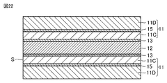
- the anti-vibration tool holder according to Embodiment 3 has basically the same configuration as the anti-vibration tool holder 10 according to Embodiment 1, but as shown in FIG. It differs from the anti-vibration tool holder 10 in that it includes 11C and a fourth base material 11D. Differences from the anti-vibration tool holder 10 will be mainly described below.
- the third base material 11C has a surface S exposed on the surface of the base material 11.
- the exposed surface S of the third base material 11C is included in the surface that comes into contact with the spindle or the tool when the anti-vibration tool holder according to Embodiment 3 is attached to the spindle of the processing machine and grips the tool.
- the surfaces of the third base material 11 ⁇ /b>C only the exposed surface S is exposed on the surface of the base material 11 .
- the rest of the surface of the third base material 11C is not exposed on the surface of the base material 11.
- the third base member 11C is arranged, for example, to surround each of the plurality of vibration dampers 12 .
- the hardness of the material forming the third base material 11C is higher than the hardness of the material forming the fourth base material 11D.
- hardness means Vickers hardness.
- the material forming the third base material 11C includes, for example, at least one of the third group consisting of stainless steel, alloy tool steel, high-speed tool steel, and cemented carbide.
- the material forming the third base material 11C includes a fifth metal different from the first metal.
- the material constituting the fourth base material 11D includes at least one selected from the first group consisting of carbon steel, chromium molybdenum steel, nickel chromium molybdenum steel, and cemented carbide.
- a material forming the fourth base material 11D includes a sixth metal different from the fifth metal.
- An intermetallic compound layer 13 is formed on the interface between the third base material 11C and each of the plurality of vibration dampers 12 .
- An intermetallic compound layer 15 is formed at the interface between the third base material 11C and the fourth base material 11D.
- the intermetallic compound layer 13 contains a compound of the fifth metal and the second metal contained in the plurality of vibration dampers 12 .
- the intermetallic compound layer 15 contains a compound of a fifth metal and a sixth metal.
- the plurality of third base materials 11C has exposed surfaces S exposed on the surface of the base material 11 of the anti-vibration tool holder, and the third base materials 11C is harder than the material constituting the fourth base material 11D. Therefore, in the anti-vibration tool holder according to Embodiment 3, the wear of the base material 11 is suppressed as compared with the anti-vibration tool holder 10 .
- At least the peripheral region of the region R irradiated with the laser L when forming the layered structure of the base material 11 may be cooled.
- at least the peripheral region of the region irradiated with the laser L may be cooled when forming the layered structure of the second base material 11B. From a different point of view, when melting a raw material with a relatively high melting point, the peripheral region of the region irradiated with the laser L to melt the raw material may be cooled below the melting point of the raw material. .
- the peripheral region to be cooled is a modeled object in the same layer as the region R irradiated with the laser L, and is a layered model formed by melting and then solidifying a raw material having a relatively low melting point. Including things.
- the peripheral region is, for example, a layered product immediately below the region R irradiated with the laser L, and further includes a layered product formed by melting and then solidifying a raw material having a relatively low melting point. include.
- the cooling is performed by at least one cooling unit 203.
- the cooling part 203 is provided so as to inject, for example, a low-temperature heat medium A (for example, gas or liquid).
- the low-temperature heat medium is, for example, carbon dioxide (dry ice) or nitrogen (liquid nitrogen), but is not limited thereto.
- the cooling may be performed by a plurality of cooling units 203.
- Each of the plurality of cooling units 203 is provided to inject a low-temperature heat medium (for example, gas or liquid) to the peripheral area surrounding the area R.
- a low-temperature heat medium for example, gas or liquid
- the plurality of cooling units 203 for example, in a side view, fan-shaped regions formed between the region R, the raw material M supplied to the region R from the supply unit 201, and the laser L irradiated to the region R from the light source 202. They are arranged so as to sandwich them.
- the area surrounding the area irradiated with the laser L to melt the raw material may be cooled below the melting point of the raw material.
- the layered object formed by melting and then solidifying the raw material that is positioned immediately below the region irradiated with the laser L and has a relatively low melting point melts and solidifies again.
- the shape and dimensions of the anti-vibration tool holder obtained by the layered manufacturing process may differ greatly from the designed shape and dimensions of the anti-vibration tool holder.
- the layered object formed by melting and then solidifying the raw material that is positioned immediately below the region irradiated with the laser L and has a relatively low melting point is Re-melting can be suppressed.
- FIG. 13 shows an example in which the cooling is applied to the DED method
- the cooling can also be applied to the PBF method.
- the peripheral region to be cooled is a modeled object in the same layer as the region R irradiated with the laser L, and is formed by melting and then solidifying a raw material having a relatively low melting point. including layered structures.
- At least one vibration damping body 12 is arranged inside at least one of the shank portion 1 and the arbor portion 2 of the base material 11 .
- the arrangement of at least one vibration damping body 12 can be changed as appropriate, for example, according to the mode of chatter vibration that occurs during machining.
- At least one vibration damper 12 is arranged, for example, at least inside the arbor section 2 .
- each of the plurality of vibration dampers 12 in the cross section perpendicular to the axis C is not limited to the shape shown in FIG.
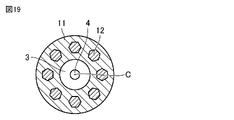
- the shape of each of the plurality of vibration dampers 12 in a cross section perpendicular to the axis C may be any of the shapes shown in FIGS. 14-19.
- Each of the plurality of vibration dampers 12 may have a cross-sectional shape different from each other.
- the anti-vibration tool holders according to Embodiments 1 to 3 are provided with a plurality of vibration dampers 12 spaced apart from each other in the circumferential direction with respect to the axis C. good.
- the first vibration damper 5, the second vibration damper 6, the third vibration damper 7, and the fourth vibration damper 8 , and the fifth vibration damping body 9 may be divided into a plurality of parts in the circumferential direction with respect to the axis C. As shown in FIG.
- a plurality of (for example, three) vibration dampers 12 may be spaced apart from each other in the circumferential direction with respect to the axis C.
- Each of the plurality of vibration dampers 12 that are spaced apart from each other in the circumferential direction with respect to the axis C are provided rotationally symmetrical with respect to the axis C, for example.
- the distance (interval) between two vibration dampers 12 adjacent in the circumferential direction is, for example, shorter than the length of each of the two vibration dampers 12 in the circumferential direction.
- a second group of vibration dampers 12B spaced apart from each other on a second circle drawn on the outside may be arranged. From a different point of view, at least one of the first vibration damper 5, the second vibration damper 6, the third vibration damper 7, the fourth vibration damper 8, and the fifth vibration damper 9 is the first group 12A and the second group of vibration dampers 12B.
- Each of the vibration damping bodies 12A of the first group has, for example, the same shape and size as each other.
- Each of the second group of vibration dampers 12B has, for example, the same shape and size as each other.
- Each of the first group of vibration dampers 12A and each of the second group of vibration dampers 12B are provided rotationally symmetrical with respect to the axis C, for example.
- the distance between two circumferentially adjacent vibration damping bodies 12A among the vibration damping bodies 12A of the first group is, for example, shorter than the circumferential length of each of the two vibration damping bodies 12A.
- the distance between two circumferentially adjacent vibration damping bodies 12B among the vibration damping bodies 12B of the second group is shorter than the circumferential length of each of the two vibration damping bodies 12B, for example.
- the distance between two vibration dampers 12B adjacent in the circumferential direction is longer than the distance between two vibration dampers 12A adjacent in the circumferential direction, for example.
- the circumferential length of each vibration damping body 12B is, for example, longer than the circumferential length of each vibration damping body 12A.
- the first group of vibration dampers 12A has, for example, a plurality of sets of vibration dampers 12A.
- Each set of vibration damping bodies 12A has two vibration damping bodies 12A arranged to face each other with the axis C interposed therebetween.
- the second group of vibration dampers 12B has, for example, a plurality of sets of vibration dampers 12B.
- Each set of vibration damping bodies 12B has two vibration damping bodies 12B arranged to face each other with the axis C interposed therebetween.
- Each vibration damping body 12B includes, for example, both end portions arranged so as to overlap each of the two vibration damping bodies 12A adjacent in the circumferential direction in the radial direction with respect to the axis C, and the two vibration damping bodies in the radial direction. It has a part of the base material 11 positioned between 12A and a central part arranged so as to overlap. At least one of the first group of vibration damping bodies 12A and the second group of vibration damping bodies 12B is represented on any cross section passing through the axis C. It is set up so that it can be released.
- the circumferential length of each of the plurality of vibration dampers 12 spaced apart from each other in the circumferential direction with respect to the axis C is equal to the axis of each of the plurality of vibration dampers 12. It may be shorter than the radial length for C.
- the circumferential length of each of the plurality of vibration dampers 12 spaced apart from each other in the circumferential direction with respect to the axis C may be shorter than the distance between two circumferentially adjacent vibration dampers 12. good.
- each of the plurality of vibration dampers 12 spaced apart from each other in the circumferential direction with respect to the axis C may be circular.
- each of the plurality of vibration dampers 12 spaced apart from each other in the circumferential direction with respect to the axis C may be quadrangular, square or rectangular.
- each of the plurality of vibration dampers 12 spaced apart from each other in the circumferential direction with respect to the axis C may be hexagonal.
- an anti-vibration tool holder can be manufactured by the additive manufacturing method described above, but can also be manufactured by casting.
- a method for manufacturing an anti-vibration tool holder according to this modification comprises a step of forming an anti-vibration tool holder including a base material 11 and at least one vibration damping body 12 by casting.
- the step of forming the anti-vibration tool holder by casting includes a step of casting a base material 11 having at least one hollow portion using a mold and a core (S3); After the removal, a step (S4) of forming one vibration damping body 12 in at least one hollow portion using the base material 11 as a mold.
- the melting point of the material forming the vibration damping body 12 is lower than the melting point of the material forming the base material 11 . Even in this way, the anti-vibration tool holder according to this modified example can be manufactured.
- the intermetallic compound layer 13 may be formed on the interface between the fourth base material 11D and each of the plurality of vibration dampers 12.
- the anti-vibration tool holder according to Embodiment 3 includes a metal mixture layer 13 formed at the interface between some vibration damping bodies 12 out of the plurality of vibration damping bodies 12 and the third base material 11C, and a plurality of The metal mixture layer 13 formed at the interface between the remaining vibration damping bodies 12 of the vibration damping bodies 12 and the fourth base material 11D may be provided.
- the second base material 11B of the anti-vibration tool holder according to the second embodiment includes the third base material 11C and the fourth base material 11D of the anti-vibration tool holder according to the third embodiment.
- the vibration damping body 12, the intermetallic compound layer 13, the first base material 11A, the intermetallic compound layer 14, the third base material 11C, the intermetallic compound layer 15, and the fourth base material 11D are laminated in order.
Landscapes
- Engineering & Computer Science (AREA)
- Mechanical Engineering (AREA)
- Cutting Tools, Boring Holders, And Turrets (AREA)
Abstract
Porte-outil anti-vibrations (10) présentant un axe (C) et étant entraîné en rotation autour de l'axe par un arbre principal d'une machine de traitement. Le porte-outil anti-vibrations (10) comprend un substrat (11) qui comporte une partie tige (1) fixée à l'arbre principal et une partie mandrin (2) destinée à saisir un outil, et au moins un atténuateur de vibrations (12) qui est disposé à l'intérieur de la partie tige (1) et/ou de la partie mandrin (2) du substrat (11). Le matériau constituant le substrat (11) comporte un premier métal. Le matériau constituant ledit atténuateur de vibrations (12) comporte un second métal différent du premier métal. Une couche de composé intermétallique qui comporte un mélange des premier et second métaux est formée au niveau de l'interface entre le substrat (11) et ledit atténuateur de vibrations (12).
Priority Applications (1)
| Application Number | Priority Date | Filing Date | Title |
|---|---|---|---|
| JP2023517460A JP7580583B2 (ja) | 2021-04-28 | 2022-04-19 | 防振工具ホルダおよびその製造方法 |
Applications Claiming Priority (2)
| Application Number | Priority Date | Filing Date | Title |
|---|---|---|---|
| JP2021-076386 | 2021-04-28 | ||
| JP2021076386 | 2021-04-28 |
Publications (1)
| Publication Number | Publication Date |
|---|---|
| WO2022230724A1 true WO2022230724A1 (fr) | 2022-11-03 |
Family
ID=83846870
Family Applications (1)
| Application Number | Title | Priority Date | Filing Date |
|---|---|---|---|
| PCT/JP2022/018191 WO2022230724A1 (fr) | 2021-04-28 | 2022-04-19 | Porte-outil anti-vibrations et son procédé de fabrication |
Country Status (1)
| Country | Link |
|---|---|
| WO (1) | WO2022230724A1 (fr) |
Citations (8)
| Publication number | Priority date | Publication date | Assignee | Title |
|---|---|---|---|---|
| US2426359A (en) * | 1944-06-24 | 1947-08-26 | Lankheet Sander | Boring bar |
| JPS384497Y1 (fr) * | 1956-05-26 | 1963-03-20 | ||
| JPS5038878A (fr) * | 1973-07-16 | 1975-04-10 | ||
| JPH0164301U (fr) * | 1987-10-21 | 1989-04-25 | ||
| JP2004202649A (ja) * | 2002-12-26 | 2004-07-22 | Sumitomo Electric Ind Ltd | 切削工具 |
| JP2005508757A (ja) * | 2001-11-13 | 2005-04-07 | カミート アーベー | 工具及びその製造方法 |
| WO2019239397A1 (fr) * | 2018-06-12 | 2019-12-19 | Iscar Ltd. | Porte-outil ayant un composant anti-vibration formé d'un seul tenant et outil de coupe pourvu d'un porte-outil |
| DE102020115678A1 (de) * | 2019-07-17 | 2021-01-21 | Kennametal Inc. | Schneidwerkzeughalter mit verbesserter dämpfungswirkung |
-
2022
- 2022-04-19 WO PCT/JP2022/018191 patent/WO2022230724A1/fr active Application Filing
Patent Citations (8)
| Publication number | Priority date | Publication date | Assignee | Title |
|---|---|---|---|---|
| US2426359A (en) * | 1944-06-24 | 1947-08-26 | Lankheet Sander | Boring bar |
| JPS384497Y1 (fr) * | 1956-05-26 | 1963-03-20 | ||
| JPS5038878A (fr) * | 1973-07-16 | 1975-04-10 | ||
| JPH0164301U (fr) * | 1987-10-21 | 1989-04-25 | ||
| JP2005508757A (ja) * | 2001-11-13 | 2005-04-07 | カミート アーベー | 工具及びその製造方法 |
| JP2004202649A (ja) * | 2002-12-26 | 2004-07-22 | Sumitomo Electric Ind Ltd | 切削工具 |
| WO2019239397A1 (fr) * | 2018-06-12 | 2019-12-19 | Iscar Ltd. | Porte-outil ayant un composant anti-vibration formé d'un seul tenant et outil de coupe pourvu d'un porte-outil |
| DE102020115678A1 (de) * | 2019-07-17 | 2021-01-21 | Kennametal Inc. | Schneidwerkzeughalter mit verbesserter dämpfungswirkung |
Also Published As
| Publication number | Publication date |
|---|---|
| JPWO2022230724A1 (fr) | 2022-11-03 |
Similar Documents
| Publication | Publication Date | Title |
|---|---|---|
| JP5878604B1 (ja) | 複合材の製造方法 | |
| US10663023B2 (en) | Hybrid lightweight brake disk and production method | |
| CN102672422B (zh) | 一种齿轮箱体的制作方法 | |
| JP5940712B1 (ja) | 加工機械 | |
| US10695838B2 (en) | Tool body, a tool and a method for manufacturing a tool body | |
| Park | Development and analysis of ultrasonic assisted friction stir welding process | |
| JP5129547B2 (ja) | Mmcリング要素およびmmc翼形を有する翼形要素を有するロータを製造するためのシステム | |
| US20070298275A1 (en) | Damped automotive components with cast in place inserts and method of making same | |
| US20030147712A1 (en) | Tool holder | |
| CN102039494A (zh) | 用于焊接由耐高温的超合金制成的工件的方法和装置 | |
| US11104063B2 (en) | Method of processing a surface for additive manufacturing, component and apparatus | |
| WO2011045980A1 (fr) | Outil de perçage | |
| JP2018075704A (ja) | 工具担持ワークスピンドルを備えた数値制御工作機械にて工具本体を製作するために硬い金属からなるワークピースを加工する方法 | |
| US20140301798A1 (en) | Cutting tool and method of manufacturing the same | |
| KR101007592B1 (ko) | 하이브리드 마찰 교반 접합장치 | |
| WO2022230724A1 (fr) | Porte-outil anti-vibrations et son procédé de fabrication | |
| JP7580583B2 (ja) | 防振工具ホルダおよびその製造方法 | |
| Balbaa et al. | A novel post-processing approach towards improving hole accuracy and surface integrity in laser powder bed fusion of IN625 | |
| JP7040504B2 (ja) | 切削用工具 | |
| US20220347763A1 (en) | Machine tool component and method for producing the machine tool component | |
| US20160377140A1 (en) | Boring bars and methods of making the same | |
| JP2016106036A (ja) | 工作機械 | |
| Khan et al. | Repurposing welding waste stubs and wires as substrate in directed energy deposition processes | |
| JP7523187B1 (ja) | 切削工具及び円筒形物品の製造方法 | |
| JP7514377B1 (ja) | 付加加工部材の製造方法 |
Legal Events
| Date | Code | Title | Description |
|---|---|---|---|
| 121 | Ep: the epo has been informed by wipo that ep was designated in this application |
Ref document number: 22795637 Country of ref document: EP Kind code of ref document: A1 |
|
| ENP | Entry into the national phase |
Ref document number: 2023517460 Country of ref document: JP Kind code of ref document: A |
|
| NENP | Non-entry into the national phase |
Ref country code: DE |
|
| 122 | Ep: pct application non-entry in european phase |
Ref document number: 22795637 Country of ref document: EP Kind code of ref document: A1 |